Published: March 25, 2011 r2011 American Chemical Society 1585 dx.doi.org/10.1021/bm101584c | Biomacromolecules 2011, 12, 1585–1593 ARTICLE pubs.acs.org/Biomac Formation and Properties of ChitosanCellulose Nanocrystal PolyelectrolyteMacroion Complexes for Drug Delivery Applications Hezhong Wang and Maren Roman* Macromolecules and Interfaces Institute and Department of Wood Science and Forest Products, Virginia Tech, Blacksburg, Virginia 24061, United States b S Supporting Information ’ INTRODUCTION The release of therapeutic agents from conventional oral drug formulations generally occurs by dissolution and diffusion of the drug from the formulation into the intestinal fluid. Single-unit formulations, such as tablets, have an unfavorable surface-area- to-volume ratio, limiting the rate of diffusion of the drug. In addition, release of the drug is confined to a small area of the small intestine, causing high local drug concentrations. Multi- particulate dosage forms have several advantages over single-unit formulations: (1) they distribute more uniformly in the gastro- intestinal tract, resulting in more uniform drug release and a reduced risk of local irritation, (2) their larger surface-area-to- volume ratio provides a larger interface for partitioning and release of the drug, and (3) particles <10 μm in diameter are assumed to enter the intestinal mucosa and therefore enable longer residence times in the intestine and close contact between the dosage form and the site of absorption. 1 A material that has received substantial attention for the preparation of multiparticulate oral drug delivery systems is chitosan, a linear copolysaccharide of β(14)-linked 2-amino- 2-deoxy-D-glucopyranose (GlcN) and 2-acetamido-2-deoxy-D- glucopyranose residues. 2,3 In acidic media, the amino groups of the GlcN residues are protonated and bear a positive charge. Chitosan has the ability to adhere to the intestinal mucosa, 4 thus prolonging the formulation's transit time through the small intestine and releasing the drug near the site of absorption, as well as to open up the tight junctions in the intestinal epithelium, 5,6 thus increasing the flux of drugs through the intestinal epithelium. With an oral LD50 in mice of >16 g/kg, 7 chitosan is considered to be nontoxic. The high molecular weight of commercial chitosan limits its oral bioavailability, reducing the potential for systemic cytotoxicity. 8 Chitosan is currently sold in the U.S. as a dietary supplement to aid weight loss and lower cholesterol and is approved as a food additive in Japan, Italy, and Finland. Several methods for the preparation of multiparticulate chit- osan drug delivery systems have been explored, including chemical cross-linking with glutaraldehyde, ionic cross-linking with tripolyphosphate, and ionic cross-linking with negatively charged polyelectrolytes. 9,10 Ionic cross-linking is generally pre- ferred because of the mild conditions during particle preparation and the absence of toxic substances. Complexation with nega- tively charged polyelectrolytes is attractive because it allows tailoring of the properties of the resulting particles, such as size, cross-linking density, solubility, swelling behavior, and pH sensitivity, through selection of a suitable polyanion. Polyanions that have been studied for the complexation with chitosan include alginate, 11 hyaluronic acid, 12,13 xanthan, 14,15 pectin, 16 poly- γ-glutamic acid, 17 carboxymethyl cellulose, 18 κ-carrageenan, 19,20 chondroitin sulfate, 12 heparin, 21 chitosan sulfate, 22 and dextran sulfate. 23,24 The properties of polyelectrolyte complexes (PECs) depend on the characteristics of the two polyelectrolytes, such as the nature of the ionizable groups (strong or weak), position of ionic sites, charge density, molecular weight, chain flexibility, functional Received: December 29, 2010 Revised: March 2, 2011 ABSTRACT: This study examines a novel polyelectroly- temacroion complex (PMC) between chitosan, a cationic polysaccharide, and cellulose nanocrystals (CNCs), anionic, cylindrical nanoparticles, for potential applications in drug delivery. CNCs were prepared by H 2 SO 4 hydrolysis of wood pulp. The formation of PMCs was monitored by turbidimetric titration. In titrations of a chitosan solution with a CNC suspension, the turbidity reached a plateau, but it had a maximum and then decreased when the direction of titration was reversed. PMC particles were characterized by Fourier transform infrared spectroscopy, scanning electron microscopy, dynamic light scattering, and laser Doppler electrophoresis. The particles were composed primarily of CNCs and ranged in size from a few hundred nanometers to several micrometers, depending on the cellulose/chitosan ratio. Particles formed at amino/sulfate group molar ratios >1 were nearly spherical in shape and positively charged, whereas particles formed at ratios <1 had well-defined nonspherical shapes and were negatively charged.
Transcript
Published: March 25, 2011
r 2011 American Chemical Society 1585 dx.doi.org/10.1021/bm101584c | Biomacromolecules 2011, 12, 1585–1593
ARTICLE
pubs.acs.org/Biomac
Formation and Properties of Chitosan�Cellulose NanocrystalPolyelectrolyte�Macroion Complexes for Drug Delivery ApplicationsHezhong Wang and Maren Roman*
Macromolecules and Interfaces Institute and Department of Wood Science and Forest Products, Virginia Tech, Blacksburg,Virginia 24061, United States
bS Supporting Information
’ INTRODUCTION
The release of therapeutic agents from conventional oral drugformulations generally occurs by dissolution and diffusion of thedrug from the formulation into the intestinal fluid. Single-unitformulations, such as tablets, have an unfavorable surface-area-to-volume ratio, limiting the rate of diffusion of the drug. Inaddition, release of the drug is confined to a small area of thesmall intestine, causing high local drug concentrations. Multi-particulate dosage forms have several advantages over single-unitformulations: (1) they distribute more uniformly in the gastro-intestinal tract, resulting in more uniform drug release and areduced risk of local irritation, (2) their larger surface-area-to-volume ratio provides a larger interface for partitioning andrelease of the drug, and (3) particles <10 μm in diameter areassumed to enter the intestinal mucosa and therefore enablelonger residence times in the intestine and close contact betweenthe dosage form and the site of absorption.1
A material that has received substantial attention for thepreparation of multiparticulate oral drug delivery systems ischitosan, a linear copolysaccharide of β(1�4)-linked 2-amino-2-deoxy-D-glucopyranose (GlcN) and 2-acetamido-2-deoxy-D-glucopyranose residues.2,3 In acidic media, the amino groups ofthe GlcN residues are protonated and bear a positive charge.Chitosan has the ability to adhere to the intestinal mucosa,4 thusprolonging the formulation's transit time through the smallintestine and releasing the drug near the site of absorption, aswell as to open up the tight junctions in the intestinalepithelium,5,6 thus increasing the flux of drugs through theintestinal epithelium. With an oral LD50 in mice of >16 g/kg,7
chitosan is considered to be nontoxic. The high molecular weightof commercial chitosan limits its oral bioavailability, reducing thepotential for systemic cytotoxicity.8 Chitosan is currently sold inthe U.S. as a dietary supplement to aid weight loss and lowercholesterol and is approved as a food additive in Japan, Italy, andFinland.
Several methods for the preparation of multiparticulate chit-osan drug delivery systems have been explored, includingchemical cross-linking with glutaraldehyde, ionic cross-linkingwith tripolyphosphate, and ionic cross-linking with negativelycharged polyelectrolytes.9,10 Ionic cross-linking is generally pre-ferred because of the mild conditions during particle preparationand the absence of toxic substances. Complexation with nega-tively charged polyelectrolytes is attractive because it allowstailoring of the properties of the resulting particles, such as size,cross-linking density, solubility, swelling behavior, and pHsensitivity, through selection of a suitable polyanion. Polyanions thathave been studied for the complexation with chitosan includealginate,11 hyaluronic acid,12,13 xanthan,14,15 pectin,16 poly-γ-glutamicacid,17 carboxymethyl cellulose,18 κ-carrageenan,19,20 chondroitinsulfate,12 heparin,21 chitosan sulfate,22 and dextran sulfate.23,24 Theproperties of polyelectrolyte complexes (PECs) depend on thecharacteristics of the two polyelectrolytes, such as the nature ofthe ionizable groups (strong or weak), position of ionic sites,charge density, molecular weight, chain flexibility, functional
Received: December 29, 2010Revised: March 2, 2011
ABSTRACT: This study examines a novel polyelectroly-te�macroion complex (PMC) between chitosan, a cationicpolysaccharide, and cellulose nanocrystals (CNCs), anionic,cylindrical nanoparticles, for potential applications in drugdelivery. CNCs were prepared by H2SO4 hydrolysis of woodpulp. The formation of PMCs was monitored by turbidimetrictitration. In titrations of a chitosan solution with a CNCsuspension, the turbidity reached a plateau, but it had amaximum and then decreased when the direction of titrationwas reversed. PMC particles were characterized by Fourier transform infrared spectroscopy, scanning electron microscopy, dynamiclight scattering, and laser Doppler electrophoresis. The particles were composed primarily of CNCs and ranged in size from a fewhundred nanometers to several micrometers, depending on the cellulose/chitosan ratio. Particles formed at amino/sulfate groupmolar ratios >1 were nearly spherical in shape and positively charged, whereas particles formed at ratios <1 had well-definednonspherical shapes and were negatively charged.
group structure, hydro- and lipophilicity, and stereoregularity butalso on the reaction conditions, such as pH, ionic strength,polyelectrolyte concentration, mixing ratio, and temperature.
In recent years, ionic complexes between polyelectrolytes andnanoscale macroions have received intense interest in soft matterscience and polymer physics on account of their widespreadoccurrence in nature.25 The science of polyelectroly-te�macroion complexes (PMCs) lies at the interface betweenthe well-studied fields of PECs and colloid�polymer systems,with the latter having traditionally focused on colloidal particlesthat are much larger than polymer coils.
In this study, we have examined a novel PMC betweenchitosan and negatively charged cellulose nanocrystals (CNCs)to test the hypothesis that such PMCs have desirable propertiesfor use as amultiparticulate oral drug delivery system. Cellulose isa linear polysaccharide of β(1�4)-linked D-glucopyranose resi-dues and is structurally very similar to chitosan. Cellulose exists innature in the form of highly crystalline fibrils with nanoscalecross-sectional dimensions. CNCs were discovered in 1949 byBengt R�anby,26 a Swedish scientist, and attracted interest in the1990s for their ability to form chiral-nematic liquid crystallinephases, a consequence of their cylindrical shape.27,28 CNCs aregenerally prepared by hydrolysis of a purified cellulose startingmaterial with either HCl or H2SO4.
29,30 Crystalline celluloseparticles prepared with HCl have been used as a pharmaceuticalexcipient since 1966.31 As opposed to the particles obtained byHCl hydrolysis, CNCs obtained with H2SO4 have sulfate groupson their surface arising from partial esterification of the surfacehydroxyl groups during the hydrolysis.32 At neutral and basic pHvalues, the sulfate groups are dissociated and bear a negativecharge. As a consequence, CNCs prepared with H2SO4 areanionic in nature.
The objectives of this study were to investigate the formationof chitosan�CNC PMCs at different CNC concentrations andmixing sequences and to determine the properties of the result-ing PMC particles, specifically their composition, size, shape, andnet charge.
’EXPERIMENTAL SECTION
Materials. Chitosan (“medium molecular weight”, FlukaBioChemika) was purchased from Sigma-Aldrich and purified as follows.Typically, 1 g of chitosan was dissolved overnight in 250 mL of 0.1 NHCl, and the solution was filtered through a series of Milliporepolyvinylidene fluoride (PVDF) syringe filters (pore sizes 1, 0.45, and0.22 μm). Next, chitosan was precipitated by the addition of 1 N NaOHuntil the solution pH reached 9 to 10. The purified chitosan wascollected by centrifugation (4900 rpm for 15 min at 4 �C), washedthree times with deionized water, and freeze-dried overnight.
Cellulose, in the form of dissolving-grade softwood sulfite pulp(Temalfa 93 A-A), was kindly provided by Tembec. H2SO4 (>95%),HCl (0.1 N, certified), NaOH (0.1 and 1 N, certified), acetic acid(glacial, certified plus), andNaCl (certified) were purchased from FisherScientific. Sodium acetate (anhydrous, 99%) was purchased from AlfaAesar. The water used in the experiments was deionized water from aMillipore Direct-Q 5 ultrapure water system (resistivity at 25 �C: 18.2MΩ 3 cm).Preparation of Chitosan Solutions. Chitosan solutions for the
complexation experiments and chitosan characterization procedureswere prepared from a stock solution of ∼0.1% (w/v) by dilution withdeionized water. For preparation of the stock solution, purified chitosanwas dried in an oven at 105 �C for 2 h. Then, 0.1 g of the oven-dried,purified chitosan was dissolved in 100 mL of 0.1 N HCl. The exact
concentration of the stock solution was determined in triplicate bythermogravimetric analysis. To this end, 30 μL of the stock suspensionwas heated under nitrogen in a TA Instruments Q5000 TGA to 120 �Cat a heating rate of 20 �C/min and held isothermal for 10 min. Theconcentration was determined from the initial suspension volume andthe residual weight. If needed, the pH and ionic strength of the dilutechitosan solutions were adjusted with 0.1 N HCl or 0.1 N NaOH andNaCl, respectively.Characterization of Chitosan. The molecular weight of the
purified chitosan was calculated from the intrinsic viscosity, obtainedfrom a series of viscosity measurements at different concentrations (0.1to 1 mg/mL). Measurements were performed with the solvent systemproposed by Rinaudo et al.33 (0.3 M acetic acid/0.2 M sodium acetate)at 25 �C with an Ubbelohde capillary viscometer having an innercapillary diameter of 0.53 mm. In this method, extrapolation of a plotof reduced viscosity, η/c, versus c to c = 0 yields the intrinsic viscosity,[η], from which the viscosity-average molecular weight, Mv, can becalculated using the Mark�Houwink equation
½η� ¼ KMva ð1Þ
The Mark�Houwink parameters, K and a, were obtained from theliterature.33,34 The intrinsic viscosity was measured in quadruplicate.
The degree of deacetylation (DD) of the chitosan sample wasdetermined by 1H nuclear magnetic resonance (NMR) spectroscopyaccording to ASTM standard F2260-03.35 Specifically, 10 mg of purifiedand oven-dried chitosan was dissolved in a mixture of 1.96 mL of D2Oand 0.04mL of DCl. Approximately 1mL of the solution was transferredto an NMR tube (diameter = 5 mm). 1HNMR spectra were acquired ona Varian Unity 400 MHz NMR spectrometer at 90( 1 �C. TheDD wascalculated as36
DD ¼ H1DðH1DþHAc=3Þ
� �� 100% ð2Þ
whereH1D is the integral of the H1GlcN peak andHAc is the integral ofthe peak corresponding to the three protons of the GlcNAc acetyl group.
The z-average hydrodynamic diameter (cumulants mean) and elec-trophoretic mobility of chitosan weremeasured with aMalvern ZetasizerNano ZSwithMalvern DTS1060 folded capillary cells and a 0.001% (w/v) chitosan solution without adjustment of the pH or ionic strength.Measurements were performed in triplicate at 25 �C.
The amino group density of the purified chitosan was measured intriplicate by conductometric titration with a Mettler Toledo SevenMultiS47 pH/conductivity meter with an InLab 730 conductivity probe. Astandard NaOH solution (0.1 N) was added dropwise under nitrogenand stirring to 25 mL of a 0.1% (w/v) chitosan solution, having an ionicstrength of 0.1 M. At every 10th drop, the conductivity of the chitosansolution was recorded. The amino group density was calculated from thetitrant volume between the two equivalence points.Synthesis of CNCs. CNCs were prepared according to the method
of Revol et al.,27 with some minor modifications. Dissolving-gradesoftwood sulfite pulp was milled in a Thomas Wiley Mini-Mill so thatit passed a 60-mesh screen. The milled pulp (50 g) was treated understirring with amechanical stirrer with 500mL of 64 wt %H2SO4 at 45 �Cfor 45 min. The hydrolysis was stopped by 10-fold dilution of thereaction medium with deionized water. The CNCs were collected bycentrifugation for 15 min at 4900 rpm under cooling (4 �C) andredispersed in deionized water after discarding of the supernatant. Forremoval of the remaining acid, the nanocrystals were dialyzed againstdeionized water with regenerated cellulose dialysis tubing (Spectra/Por4, Spectrum Laboratories, MWCO 12�14 kDa) until the pH of thedialysis water stayed constant. The obtained suspension was sonicatedunder ice-bath cooling for 15 min at 40% output with a 500W ultrasonicprocessor (Sonics & Materials, model VC-505). Finally, the suspensionwas filtered through a 0.45 μm and then 0.22 μm PVDF syringe filter.
The concentration of the filtered CNC stock suspension, determined intriplicate from theweight difference of a 5mL aliquot before and after dryingfor 2 h in an oven at 80 �C, was generally in the range of 0.6 to 0.9% (w/v).Preparation of CNC Suspensions. Dilute CNC suspensions for
the complexation experiments and CNC characterization procedures wereprepared from the filtered stock suspension by dilution with deionizedwater. If needed, the pH and ionic strength of the dilute CNC suspensionswere adjusted with 0.1 N HCl or 0.1 N NaOH and NaCl, respectively.Characterization of CNCs. The morphology of the resulting
CNCs was characterized by atomic force microscopy (AFM). A 10 μLdrop of a 0.001% (w/v) CNC suspension was spin-coated at 2000 rpmwith a Laurell Technologies WS-400B-6NPP/LITE spin coater onto afreshly cleaved mica disk (V1 mica, 9.9 mm diameter, Ted Pella). Themica disk was then mounted onto a standard microscope slide withepoxy adhesive. AFM images were recorded in AC mode in air with anAsylum Research MFP-3D-Bio and standard silicon probes (Olympus-AC160TS, nominal tip radius: <10 nm, nominal force: 42 N/m).
The z-average hydrodynamic diameter (cumulants mean) and elec-trophoretic mobility of the CNCs were measured with a MalvernZetasizer Nano ZS with Malvern DTS1060 folded capillary cells and a0.02% (w/v) CNC suspension without adjustment of the pH or ionicstrength. Measurements were performed in triplicate at 25 �C.
The sulfate group density of the CNCs was measured in triplicate byconductometric titration with a Mettler Toledo SevenMulti S47 pH/conductivity meter with an InLab 730 conductivity probe. Titrationswere carried out with 25 mL aliquots of the filtered stock suspensionafter adjustment of the ionic strength to 1 mM through the addition ofNaCl. The titrant, 0.02 N NaOH, prepared by dilution of 0.1 N NaOHwith deionized water, was added under nitrogen gas and stirring in0.5 mL increments. After each addition, the conductivity of the CNCsuspension was recorded. The sulfate group density was calculated fromthe titrant volume at the equivalence point.Turbidimetric Titration. Turbidimetric titrations were performed
with a 0.001% (w/v) chitosan solution and a dilute CNC suspension(0.02% (w/v), unless stated otherwise), both having a pH of 2.6 and anionic strength of 1 mM. The ionic strength and pH values were chosenon the basis of preliminary screening experiments. The effect of pH andionic strength on the formation and properties of chitosan�CNCPMCswill be reported separately. In a turbidimetric titration experiment, theCNC suspension was added dropwise under vigorous stirring with amagnetic bar to the chitosan solution or vice versa. The transmittance ofthe reaction mixture was monitored with a Brinkmann PC 950 probecolorimeter with a 1 cm optical cell (2 cm path length), operating at awavelength of 420 nm. Turbidity values were calculated as 100 �transmittance (%). Prior to each titration, the probe colorimeter waszeroed in deionized water. Each experiment was performed in triplicate.Characterization of PMC Particles. The chemical composition
of the PMC particles was analyzed by Fourier transform infrared (FTIR)spectroscopy. FTIR spectra were recorded from KBr pellets with aresolution of 4 cm�1 and a number of scans of 128 with a ThermoNicolet Nexus 470 ESP FTIR spectrometer. KBr pellets were preparedby grinding 98 mg of dry KBr with 2 mg of sample and compressing themixture between the ends of two stainless steel bolts inserted fromopposite ends into a deep stainless steel nut, which served as the sampleholder. The KBr pellet was dried in an oven prior to the measurement.
The morphology of the PMC particles was analyzed by field-emissionscanning electron microscopy (FE-SEM). Images were recorded with aLEO 1550 FE scanning electronmicroscope at an accelerating voltage of1 kV and a working distance of 4 to 5 mm. Particles for SEM imagingwere prepared at different amino/sulfate groupmolar ratios (N/S ratios)by mixing under vigorous stirring with a magnetic bar the appropriateamounts of a 0.001% (w/v) chitosan solution and a 0.02% (w/v) CNCsuspension, both having a pH of 2.6 and an ionic strength of 1 mM. ForSEM sample preparation, a 10 μL drop of the PMC particle suspension
was deposited onto Ni�Cu conductive tape (Ted Pella) mounted ontoa standard SEM stub (Ted Pella) and allowed to dry under ambientconditions. Prior to imaging, the SEM samples were coated with a thin(6 nm) layer of carbon.
The z-average hydrodynamic diameter (cumulants mean) and elec-trophoretic mobility of the PMCparticles weremeasured with aMalvernZetasizer Nano ZS90 and Malvern DTS1060 folded capillary cells. ThePMC particle suspensions, obtained as described above, were useddirectly without further dilution or filtration. Measurements wereperformed in triplicate at 25 �C.
’RESULTS AND DISCUSSION
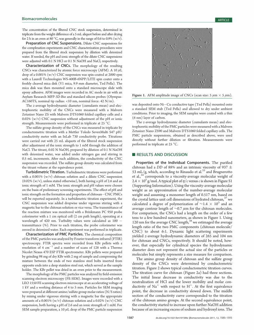
Properties of the Individual Components. The purifiedchitosan had a DD of 88% and an intrinsic viscosity of 937 (53 mL/g, which, according to Rinaudo et al.33 and Brugnerottoet al.,34 corresponds to a viscosity-average molecular weight of2.4� 105 g/mol. A typical plot of η/c versus c is shown in Figure S1(Supporting Information). Using the viscosity-average molecularweight as an approximation of the number-average molecularweight and assuming a monomer length of 0.517 nm, based onthe crystal lattice unit cell dimensions of hydrated chitosan,37 wecalculated a degree of polymerization of ∼1.4 � 103 and anaverage contour length of ∼0.7 μm for the chitosan molecules.For comparison, the CNCs had a length on the order of a fewtens to a few hundred nanometers, as shown in Figure 1. Using120 nm for the average CNC length,38 we estimaged the averagelength ratio of the two PMC components (chitosan molecule/CNC) to about 6:1. Dynamic light scattering experimentsyielded z-average hydrodynamic diameters of 265 and 104 nmfor chitosan and CNCs, respectively. It should be noted, how-ever, that especially for cylindrical species the hydrodynamicdiameter does not represent the actual size of the particles ormolecules but simply represents a size measure for comparison.The amino group density of chitosan and the sulfate group
density of the CNCs were determined by conductometrictitration. Figure 2 shows typical conductometric titration curves.The titration curve for chitosan (Figure 2a) had three sections.The initial linear decrease in conductivity was due to theneutralization of HCl and the lower mobility and molar con-ductivity of Naþ with respect to Hþ. At the first equivalencepoint, the decrease in conductivity slowed down. The middlesection of the conductivity curve corresponded to the titrationof the chitosan amino groups. At the second equivalence point,the conductivity started to increase upon further NaOH additionbecause of an increasing excess of sodium and hydroxyl ions. The
titration curve for the CNCs (Figure 2b) had two branchescorresponding to the neutralization of the partially dissociatedsurface sulfate groups (�SO3H and �SO3
� Hþ) and excessNaOH, respectively. The amino group density of chitosan was5.83 mol/kg, and the sulfate group density of the CNCs was 0.18mol/kg. In other words, the amino group density of chitosan was33 times higher than the sulfate group density of the CNCs.
Therefore, there was a strong mismatch in the densities of ionizablegroups of the two PMC components.PMC Formation.When a CNC suspension was added dropwise
to a chitosan solution of the same pH and ionic strength, the reactionmixture immediately became opaque because of the formation of aninsoluble complex. Figure 3 shows turbidimetric titration curves forthe titration of a 0.001% (w/v) chitosan solution with CNCsuspensions of different concentration. Initially, the chitosan solutionwas completely transparent. Upon dropwise addition of the CNCsuspension, the turbidity increased linearly for CNC concentrationsup to 0.02% (w/v), and the increase was more pronounced at higherconcentrations. At CNC concentrations above 0.02% (w/v), theincrease in turbidity started to be asymptotic rather than linear.At CNC concentrations above 0.02% (w/v), flocculation oc-
curred relatively early during the titration, resulting in sedimentationof the complex. Large flocs interfered with the turbidity measure-ments and caused strong fluctuations in the turbidity data (largeerror bars). The lowest CNC concentrations (0.001 and 0.01% (w/v)) gave turbidity values only slightly above the detection limit of theinstrument (∼2), which is why we chose an intermediate CNCconcentration (0.02% (w/v)) for subsequent experiments.Our results are in accordance with those of Dautzenberg et al.,39
who observed higher levels of aggregation at higher polyelectrolyteconcentrations for PEC formation between sodium poly(styrenesulfonate) and poly(diallyldimethylammonium chloride).The turbidity profile upon incremental mixing of a chitosan
solution with a CNC suspension depended on the mixingsequence. Figure 4 shows the titration curves for the titrationof a chitosan solution with a CNC suspension (type 1) and thereverse direction (type 2).In type 1 titrations, the turbidity increased rapidly initially up
to a sulfate/amino group molar ratio (S/N ratio) of∼0.5. Uponfurther increase in the S/N ratio, the turbidity leveled off andasymptotically approached a maximum turbidity level. In type 2titrations, the turbidity also increased rapidly initially up to an N/S ratio of∼0.5. The initial increase in turbidity was similar to thatobserved in type 1 titrations. However, upon further increase inthe N/S ratio, the turbidity decreased.
Figure 3. Turbidimetric titration curves for titrations of a 0.001% (w/v)chitosan solution with CNC suspensions of different concentration.(The titrand volume was 25 mL. Data points are the means of threemeasurements. Error bars represent one standard deviation. The dashedlines are guides to the eye.)
Figure 4. Turbidimetric titration curves for the titration of a 0.001%(w/v) chitosan solution with a 0.02% (w/v) CNC suspension (type 1;b, bottom x axis) and the reverse direction (type 2;4, top x axis). (Datapoints are the means of three measurements. Error bars represent onestandard deviation. The dashed lines are guides to the eye.)
Figure 2. Conductometric titration curves for the determination of (a)the amino group density of chitosan and (b) the sulfate group density ofthe CNCs.
Shybaila et al.40 made a similar observation in a study of thecomplexation of chitosan and chitosan sulfate acetate (CSA).Turbidity levels reached a plateau in titrations of a chitosan solutionwith a CSA solution but decreased after reaching a maximum intitrations of the reverse direction. The decrease in turbidity wasrelated to the presence of a low-molecular-weight electrolyte(CH3COONa). In the absence of electrolyte, the turbidity stayedconstant after reaching the maximum; that is, it exhibited a plateau.The ionic strength in our titration was 1 mM. The fact that thedecrease in turbidity was observed only in the presence ofelectrolyte suggests that it was based on charge screening effects.A subsequent study of the effect of pH on the formation of
chitosan�CNC PMCs, which will be reported separately, revealedthat at pH 2.6, which was the pH of the turbidimetric titrations, thedegree of ionization of the CNCs was 0.5, that is, only 50% of thesulfate groups were dissociated and carried a negative charge. ThepH value for the turbidimetric titrations was chosen on the basis ofpreliminary screening experiments as the lowest pH at which theCNC suspensions remained clear. As a consequence, an N/S ratioof 0.5 at pH 2.6 represents a NH3
þ/SO3� charge ratio of unity. It is
commonly accepted that PECs exhibit maximum aggregation at astoichiometric charge ratio because the net charge of the PECs iszero. At nonstoichiometric charge ratios, PECs bear a nonzero netcharge and are therefore charge stabilized. Aggregation of thechitosan�CNC PMCs due to a stoichiometric charge ratio wouldexplain the turbidity maximum at an N/S ratio of 0.5 in type 2titrations. Upon further increase in the N/S ratio, charge over-compensation by incorporation of additional chitosan moleculesinto the PMCs would lead to a net positive charge and chargestabilization of the PMCs, reversing PMC aggregation. The incor-poration of additional chitosanmolecules into thePMCsmight havebeen facilitated by the NaCl (1 mM) because of the ability of theNaþ and Cl� ions to reduce the attraction forces between the PMCcomponents through charge screening. The presence of low-molecular-weight electrolytes during PMC formation is known toenable structural rearrangements.41
In type 1 titrations, charge stoichiometry corresponded to anS/N ratio of 2 at pH 2.6, which coincided with the turbiditymaximum. The rapid increase in turbidity at low S/N ratios wasprobably related to the particulate nature of one of the PMC
components. Upon addition of CNCs to a chitosan solution, thechitosan molecules likely caused bridging flocculation. The netcharge of these flocs would be positive because of an excess ofammonium groups. Upon further increase in the S/N ratio, thenet charge of the PMC particles would decrease.To confirm this interpretation, we monitored the size and net
charge of PMC particles during type 1 and type 2 titrations. Thetitrations for this analysis were performed differently from thoseof Figure 4, which is why the ranges for the S/N and N/S ratiosare different. Table 1 lists the hydrodynamic diameters andelectrophoretic mobilities of PMC particles obtained at differentmixing ratios and sequences.At all volume ratios >0, the cellulose/chitosan mass ratio was
>1, meaning that the mass of CNCs present in the reactionmixture was always greater than that of chitosan. The cellulose/chitosan mass ratio ranged from 4 to 100. In type 1 titrations, thehydrodynamic diameter of the PMC particles increased from347 nm at an S/N ratio of 0.12 to 969 nm at an S/N ratio of 0.48.At an S/N ratio of 0.6, the reaction mixture yielded scatteringdata unsuitable for size determination of the aggregates, probablybecause of large or nonuniform floc sizes. In type 2 titrations, thehydrodynamic diameter increased more gradually, having valuesof only 154 nm at an N/S ratio of 0.33 and 410 nm at 0.66. At N/S ratios of 0.99 or higher, the reaction mixtures yielded scatteringdata unsuitable for size determination of the aggregates.During type 1 titrations, the electrophoretic mobility of the
PMC particles was positive, indicating an excess of ammoniumgroups, and decreased slightly toward the end. An excess ofammonium groups is desirable for oral drug delivery applicationsbecause a net positive charge will enable the PMC particles toadhere to the negatively charged mucosa of the small intestine,whichwill prolong their transit times through the small intestine andensure proximity of drug release to the site of absorption. Duringtype 2 titrations, the electrophoretic mobility of the PMC particleswas initially negative, indicating an excess of sulfate groups, andincreased with increasingN/S ratio. The electrophoretic mobility ofthe particles became positive at an N/S ratio of 1.33. It is importantto note, that the composition of the PMC particles, in terms ofcellulose/chitosan mass ratio and S/N or N/S ratio, most likelydiffered from that of the reaction mixture. For example, the
Table 1. PMC Particle Properties at Different Mixing Ratios and Sequencesa
volume ratio
cellulose/chitosan
mass ratio S/N ratio N/S ratio hydrodynamic diameter (nm) electrophoretic mobility (μm 3 cm/V 3 s)
Titration of a 0.001% Chitosan Solution with a 0.02% CNC Suspension (Type 1)b
0.0 0 ¥ 265( 14 4.0( 0.1
0.2 4 0.12 8.28 347( 6 2.9( 0.2
0.4 8 0.24 4.14 411( 22 3.6( 0.1
0.6 12 0.36 2.76 472 ( 17 3.4( 0.1
0.8 16 0.48 2.07 969 ( 81 3.4( 0.0
1.0 20 0.60 1.66 c 2.5( 0.0
Titration of a 0.02% CNC Suspension with a 0.001% Chitosan Solution (Type 2)b
0.0 ¥ ¥ 0 104 ( 4 �2.8( 0.2
0.2 100 3.02 0.33 154 ( 12 �2.7 ( 0.0
0.4 50 1.51 0.66 410 ( 91 �2.4( 0.1
0.6 33 1.01 0.99 c �1.2( 0.0
0.8 25 0.75 1.33 c 1.0( 0.1
1.0 20 0.60 1.66 c 2.7( 0.1aReaction conditions: pH 2.6, ionic strength 1 mM. bAll concentrations are % (w/v). c Scattering data unsuitable for size determination.
negative electrophoretic mobility value obtained in type 2 titrationsat an N/S ratio in the reaction mixture of 0.99 (estimated tocorrespond to an NH3
þ/SO3� ratio of 2) indicated an excess of
ionized sulfate groups in the PMC particles. Consequently, thereaction mixture must have contained unreacted chitosan.The proposed mechanisms of chitosan�CNC complexation
for the two mixing sequences, based on the mechanisms of PECformation,42 are schematically shown in Figure 5. In type 1titrations, the short, rigid CNCs are added incrementally to thelonger, more flexible chitosan molecules (Figure 5a). The addedCNCs bind to the chitosan molecules and partially compensatethe positive charge along the chitosan chain, allowing the chainsto take on a more tightly coiled conformation. At this point, thenet charge of the PMCs is still positive (positive electrophoreticmobility, Table 1), but the formation of the PMCs causes anincrease in turbidity (Figure 4). Upon further addition of CNCs,more charges will be compensated, and the charge ratio willeventually reach unity. At this charge ratio, the net charge of thePMCs is close to zero, and the PMCs may aggregate, whichmanifests itself by a turbidity maximum. If more CNCs wereadded at this point, then additional CNCs would be incorporated inthe PMCs, resulting in charge overcompensation and a net negativecharge. PMC aggregation would be suppressed through repulsiveforces between the negatively charged PMCs, and the turbiditywould decrease. Unbound CNCs would be present in the reactionmixture. The stage of charge overcompensation was not realized inour experiments. A charge ratio of unity and turbidity maximummight have been realized in Figure 4 (S/N ratio of 2).In type 2 titrations, the longer, flexible chitosan molecules are
added incrementally to the short, rigid CNCs (Figure 5b). Uponaddition to the CNC suspension, the chitosan molecules rapidlybind a large number of CNCs and form dense PMCparticles withan excess of negatively charged sulfate groups (negative electro-phoretic mobility, Table 1). The formation of PMCs is mani-fested by an increase in turbidity (Figure 4). Upon furtheraddition of chitosan molecules, all CNCs present in the mixtureeventually become bound. At a charge ratio of unity, the netcharge of the PMCs is close to zero, and the PMCs mayaggregate, causing a turbidity maximum (Figure 4, N/S ratio of0.5). Further addition of chitosan molecules results in chargeovercompensation by incorporation of additional chitosan mol-ecules into the PMCs (positive electrophoretic mobility,
Table 1) and the presence of unbound chitosan molecules inthe mixture. In acidic aqueous media, loose ends of chitosanmolecules are likely to protrude from the PMC particle surface.The breaking up of PMC aggregates upon charge overcompen-sation manifests itself by a decrease in turbidity (Figure 4).Characterization of PMC Particles. The chemical composi-
tion of the PMC particles was analyzed by FTIR spectroscopy.Figure 6 shows the FTIR spectra of chitosan (Figure 6a), CNCs(Figure 6b), and PMC particles formed by mixing equal volumes ofa 0.01% (w/v) chitosan solution and a 0.01% (w/v) CNC suspen-sion. The FT-IR spectra of chitosan (Figure 6a) and CNCs(Figure 6b) were nearly identical because of the similarity of themolecular structures of chitosan and cellulose. In the spectrum ofthe CNCs, the broad absorption band between 3600 and3000 cm�1 was related to OH stretching vibrations.43 The absorp-tion bands between 3000 and 2800 cm�1 and 1500 and 1250 cm�1
stemmed from the CH and CH2 stretching and bending vibrations,respectively.44 The bands in the fingerprint region have previouslybeen assigned to the antisymmetric bridge C�O�C stretchingvibration45,46 and the CO stretching vibrations at C�2, C�3, andC�6.47 Last, the band between 800 and 450 cm�1 originated in theOH out-of-plane bending vibrations.48,49 The FT-IR spectrum ofchitosan had additional absorption bands between 1700 and1500 cm�1, stemming from carbonyl stretching vibrations (amideI band) and NH bending vibrations (amide II band).50
The FTIR spectrum of the PMC particles (spectrum (c)) wasidentical to that of the CNCs (spectrum (b)) and did not showthe characteristic absorption bands of chitosan. The absence ofchitosan absorption bands from the spectrum of the PMCparticles confirmed that the particles consisted primarily ofCNCs and that chitosan was the minor component.The PMC particles used to obtain spectrum (c) had been
isolated from the reaction mixture by centrifugation, washedthree times with deionized water, and freeze-dried. The lowchitosan content of the PMC particles indicated that part of the
Figure 5. Proposed mechanisms of chitosan�CNC complexation: (a)titration of a chitosan solution with a CNC suspension (type 1) and (b)titration of a CNC suspensionwith a chitosan solution (type 2) (drawingnot to scale).
Figure 6. FT-IR spectra of (a) chitosan, (b) CNCs, (c) PMCparticles, (d)PMC particles collected after adjusting the pH to 10, and (e) a 50:50physical blend of chitosan and CNCs. (The dotted lines indicate thelocation of the wavenumbers 1581 and 1375 cm�1. See the text for details.)
chitosan in the reaction mixture had remained in solution duringcomplex formation and been discarded with the supernatant. Totest this hypothesis, we repeated the complexation experimentbut raised the pH of the reaction mixture with 1NNaOH to∼10before centrifugation. Raising the pH caused the chitosan thathad remained in solution to precipitate and be present in thesediment after centrifugation. Spectrum (d) in Figure 6 is theFTIR spectrum obtained from the washed and freeze-driedsediment of this experiment. The characteristic absorption bandsof chitosan are clearly visible, corroborating our hypothesis thatduring complex formation a large fraction of chitosan remains insolution. Spectrum (e) is an FTIR spectrum of a 50:50 physicalblend of chitosan and CNCs, recorded for comparison.To quantify the chitosan content of the binary FTIR samples, we
analyzed the FTIR spectra further. The largest difference betweenthe absorbances of chitosan and CNCs (spectra (a) and (b) in
Figure 6, respectively) was observed at a wavelength of 1581 cm�1.At this wavelength, chitosan showed carbonyl and NH-relatedabsorption, whereas absorption by cellulose was minimal. For amore detailed view, the fingerprint regions of the spectra in Figure 6are shown in Figure S2 (Supporting Information). The absorbanceat 1375 cm�1, related to CH2 bending vibrations,
48 was used as aninternal reference. The ratios of the absorbances at 1581 and1375 cm�1 (A1581/A1375) for chitosan and cellulose as well as thethree binary FTIR samples are listed in Table 2.Assuming that this ratio is unaffected by the process of mixing
the two components, it can be used to estimate the compositionof the mixtures. The calculated chitosan contents of the threebinary FTIR samples are listed in Table 2. The values confirmthat the chitosan content of PMC particles formed by mixingequal volumes of a 0.01% (w/v) chitosan solution and a 0.01%(w/v) CNC suspension was very low. Increasing the pH to 10
Table 2. Ratios of FTIR Absorbances at 1581 and 1375 cm�1 (A1581/A1375) for Chitosan and Cellulose as well as the Three BinaryFTIR Samples and Calculated Chitosan Contents
sample A1581/A1375 chitosan content (%)
chitosan 0.76 100
CNCs 0.09 0
PMC complex particles formed by mixing equal volumes of a 0.01% (w/v)
chitosan solution and a 0.01% (w/v) CNC suspension
0.08 0
PMC complex particles collected after adjusting the pH to 10 0.40 46
50:50 physical blend of chitosan and CNCs 0.49 60
Figure 7. FE-SEM images of PMC particles formed by the addition of a 0.001% (w/v) chitosan solution to a 0.02% (w/v) CNC suspension at reactionmixture N/S ratios of (a) 0.33, (b) 0.66, (c) 0.99, (d) 1.33, and (e) 1.66. Scale bar: 3 μm (applies to all images).
before centrifugation resulted in a chitosan content close to 50%,suggesting that most of the chitosan remained in solutionduring complex formation. The high chitosan content of the“50:50” physical blend of 60% indicates either a low accuracy ofthe analysis method or insufficient mixing during samplepreparation.The morphology of the PMC particles was analyzed by FE-
SEM. Figure 7 shows SEM images of PMC particles formed bythe addition of a 0.001% (w/v) chitosan solution to a 0.02% (w/v) CNC suspension at different N/S ratios in the reactionmixture. The obtained particles ranged in size from a fewhundred nanometers to several micrometers, which is smallenough to penetrate the intestinal mucosa.1 Penetration of theintestinal mucosa is beneficial in oral drug delivery applicationsbecause it leads to longer residence times for the drug formula-tion in the small intestine and release of the drug near theepithelium, through which the drug is absorbed.At N/S ratios below 1 (Figure 7a�c), the PMC particles were
nonspherical and hadmore-or-less well-defined edges. The shapeof the particles seemed to become better defined as the N/S ratioin the reaction mixture approached 1. At N/S ratios of 0.66 and0.99, many particles appeared to have a somewhat symmetrichexagonal shape with three long and three short sides. Someparticles had four long sides and two short ones, approaching arhombus in shape. (See also Figure 8a.) Artifacts, such as saltcrystals formed by the electrolyte (1 mM NaCl), were clearlydistinguishable from the PMC particles (Figure S3, SupportingInformation), and carewas taken to image representative samples ofthe particles observed (Figure S4, Supporting Information).At N/S ratios above 1, the shape of the PMC particles becamemore and more spherical with increasing N/S ratio in thereaction mixture. The reason for the nonspherical shape of thePMC particles at the N/S ratios 0.66 and 0.99 is not clear. It islikely to be related to packing constraints due to the cylindricalshape of the CNCs. However, the spatial arrangement of theCNCs in the PMC particles is not known.Figure 8 shows two PMC particles at higher magnification.
The particle formed at an N/S ratio of 0.66 (Figure 8a) wascovered in CNCs. The cylindrical particles were also covering thesubstrate, indicating that at this N/S ratio CNCs were in excess inthe reaction mixture. Figure 8a, therefore, provides furtherevidence in support of the proposed mechanism of chito-san�CNC complexation during type 2 titrations (Figure 5b),specifically its second stage. The particle formed at an N/S ratioof 1.33 (Figure 8b), on the other hand, was coated in chitosan.The chitosan coating of the particle and the substrate indicated
that at this N/S ratio chitosan was in excess in the reactionmixture. It is noteworthy that the cellulose/chitosan mass ratio atthis N/S ratio was still 25; that is, in terms of mass, there was 25times more cellulose present in the reaction mixture thanchitosan. However, because of their 33 times lower density ofionizable groups, with respect to chitosan, most of the availableCNCs had been incorporated into PMC particles. Figure 8b,therefore, supports the fourth stage of the proposed mechanismfor type 2 titrations (Figure 5b).
’CONCLUSIONS
The objectives of this study were to investigate the formationof PMCs from chitosan and CNCs at different CNC concentra-tions and mixing sequences and to determine the properties ofthe resulting PMC particles with regard to their potentialapplication as a multiparticulate oral drug delivery system. Inlight of the above results, the following conclusions can be drawn.The formation and properties of chitosan�CNC PMC particlesare governed by the strong mismatch in the densities of ionizablegroups of the two components. The concentration of CNCs inthe reaction medium has a strong effect on PMC formation, withhigher CNC concentrations resulting in larger or more highlyaggregated PMC particles. In the presence of electrolyte and athigher mixing ratios, the formation of chitosan�CNC PMCparticles is affected by themixing sequence. Because of the strongmismatch in the densities of ionizable groups, chitosan�CNCPMC particles are composed primarily of cellulose. The size ofthe PMC particles depends on the mixing ratio of the twocomponents and ranges from a few hundred nanometers toseveral micrometers. Different mixing ratios give different parti-cle shapes, with higher chitosan proportions during PMCformation resulting in spherical particles with a net positivecharge and lower chitosan proportions resulting in nonsphericalparticles with a net negative charge. With regard to our hypoth-esis that chitosan�CNC PMCs have desirable properties for useas a multiparticulate oral drug delivery system, the study hasshown that under the experimental conditions tested PMCs withdesirable properties, that is, a net positive charge and a size <10μm, are obtained at N/S ratios g1.33.
’ASSOCIATED CONTENT
bS Supporting Information. Typical plot of η/c versus c fordetermination of the intrinsic viscosity of the purified chitosan;fingerprint regions of the FTIR spectra shown in Figure 6; FE-SEMimage of PMC particles showing salt crystals and other artifacts; andlowermagnification images of select images of Figure 7.Thismaterialis available free of charge via the Internet at http://pubs.acs.org.
This material is based on work partially supported by theUSDA/CSREES under grant 2005-35504-16088, the NationalScience Foundation under grants CHE-0724126 and DMR-0907567, and the Institute for Critical Technology and AppliedScience at Virginia Tech. Additional support from Omnova and
Figure 8. Surface morphology of PMC particles at different reactionmixture N/S ratios: (a) 0.66 and (b) 1.33 (cellulose/chitosan mass ratio:(a) 50 and (b) 25). Scale bar: 1 μm.
Tembec is also acknowledged. Parts of this work were carried outwith instruments of theNanoscale Characterization and FabricationLaboratory, a Virginia Tech facility operated by the Institute forCritical Technology and Applied Science. In particular, we thankMr. Stephen McCartney for assistance with the FE-SEM images.
’REFERENCES
(1) Galindo-Rodriguez, S. A.; Allemann, E.; Fessi, H.; Doelker, E.Crit. Rev. Ther. Drug Carrier Syst. 2005, 22, 419–463.(2) Sinha, V. R.; Singla, A. K.; Wadhawan, S.; Kaushik, R.; Kumria,
R.; Bansal, K.; Dhawan, S. Int. J. Pharm. 2004, 274, 1–33.(3) Agnihotri, S. A.; Mallikarjuna, N. N.; Aminabhavi, T. M.
Kenkyu Hokoku 1968, 56, 89–94.(8) Maher, S.; Brayden, D. J.; Feighery, L.; McClean, S. Crit. Rev.
Ther. Drug Carrier Syst. 2008, 25, 117–168.(9) Berger, J.; Reist, M.; Mayer, J. M.; Felt, O.; Peppas, N. A.; Gurny,
R. Eur. J. Pharm. Biopharm. 2004, 57, 19–34.(10) Onishi, H. J. Drug Delivery Sci. Technol. 2010, 20, 15–22.(11) George, M.; Abraham, T. E. J. Controlled Release 2006,
29, 317–323.(13) Lim, S. T.; Martin, G. P.; Berry, D. J.; Brown, M. B. J. Controlled
Release 2000, 66, 281–292.(14) Dumitriu, S.; Magny, P.; Montane, D.; Vidal, P. F.; Chornet, E.
J. Bioact. Compat. Polym. 1994, 9, 184–209.(15) Chu, C. H.; Sakiyama, T.; Yano, T. Biosci., Biotechnol., Biochem.
1995, 59, 717–719.(16) Meshali, M. M.; Gabr, K. E. Int. J. Pharm. 1993, 89, 177–181.(17) Lin, Y. H.; Chung, C. K.; Chen, C. T.; Liang, H. F.; Chen, S. C.;
Sung, H. W. Biomacromolecules 2005, 6, 1104–1112.(18) Arg€uelles-Monal, W.; Peniche-Covas, C. Makromol. Chem.,
Rapid Commun. 1988, 9, 693–697.(19) Sakiyama, T.; Chu, C. H.; Fujii, T.; Yano, T. J. Appl. Polym. Sci.
1993, 50, 2021–2025.(20) Grenha, A.; Gomes, M. E.; Rodrigues, M.; Santo, V. E.; Mano, J. F.;
Neves, N.M.; Reis, R. L. J. Biomed.Mater. Res., Part A 2010, 92A, 1265–1272.(21) Kikuchi, Y.; Noda, A. J. Appl. Polym. Sci. 1976, 20, 2561–2563.(22) Berth, G.; Voigt, A.; Dautzenberg, H.; Donath, E.; Mohwald, H.
Biomacromolecules 2002, 3, 579–590.(23) Sakiyama, T.; Takata, H.; Kikuchi, M.; Nakanishi, K. J. Appl.
(35) Standard Test Method for Determining Degree of Deacetylation inChitosan Salts by Proton Nuclear Magnetic Resonance (1H NMR) Spec-troscopy; ASTM Standard F2260-03; ASTM International: West Con-shohocken, PA, 2008; DOI: 10.1520/F2260-03R08. www.astm.org.
(36) Lavertu, M.; Xia, Z.; Serreqi, A. N.; Berrada, M.; Rodrigues, A.;Wang, D.; Buschmann, M. D.; Gupta, A. J. Pharm. Biomed. Anal. 2003,32, 1149–1158.
(37) Okuyama, K.; Noguchi, K.; Kanenari, M.; Egawa, T.; Osawa, K.;Ogawa, K. Carbohydr. Polym. 2000, 41, 237–247.
(38) Beck-Candanedo, S.; Roman, M.; Gray, D. G. Biomacromole-cules 2005, 6, 1048–1054.
(39) Dautzenberg, H.; Rother, G.; Hartmann, J. InMacroion Character-ization: From Dilute Solution to Complex Fluids; Schmitz, K. S., Ed.; ACSSymposium Series 548; American Chemical Society: Washington, DC,1993; pp 210�224.
(40) Shybaila, T. N.; Savitskaya, T. A.; Kislyakova, T. A.; Albulov,A. I.; Grinshpan, D. D. Colloid J. 2008, 70, 661–665.
(41) Bakeev, K. N.; Izumrudov, V. A.; Zezin, A. B.; Kabanov, V. A.Dokl. Akad. Nauk SSSR 1988, 299, 1405–1408.
(42) Dautzenberg, H. In Physical Chemistry of Polyelectrolytes;Radeva, T., Ed.; Marcel Dekker: New York, 2001; pp 743�792.
(43) Hinterstoisser, B.; Salm�en, L. Cellulose 1999, 6, 251–263.(44) Marchessault, R. H.; Liang, C. Y. J. Polym. Sci. 1960, 43, 71–84.(45) Nikonenko, N. A.; Buslov, D. K.; Sushko, N. I.; Zhbankov,
R. G. Biopolymers 2000, 57, 257–262.(46) Nikonenko, N. A.; Buslov, D. K.; Sushko, N. I.; Zhbankov, R. G.
J. Mol. Struct. 2005, 752, 20–24.(47) Mar�echal, Y.; Chanzy, H. J. Mol. Struct. 2000, 523, 183–196.(48) Kondo, T.; Sawatari, C. Polymer 1996, 37, 393–399.(49) Oh, S. Y.; Yoo, D. I.; Shin, Y.; Kim, H. C.; Kim, H. Y.; Chung,
Y. S.; Park, W. H.; Youk, J. H. Carbohydr. Res. 2005, 340, 2376–2391.(50) Duarte, M. L.; Ferreira, M. C.; Marvao, M. R.; Rocha, J.