5 9 0001 RECORD OF DECISION SUMMARY REMEDIAL ALTERNATIVE SELECTION FORMER SPELLMAN ENGINEERING SITE ORLANDO, ORANGE COUNTY, FLORIDA PREPARED BY: U.S. ENVIRONMENTAL PROTECTION AGENCY REGION 4 ATLANTA, GEORGIA SEPTEMBER 2004 10135666
Transcript
5 9 0001
RECORD OF DECISIONSUMMARY REMEDIAL ALTERNATIVE SELECTION
FORMER SPELLMANENGINEERING SITE
ORLANDO, ORANGE COUNTY, FLORIDA
PREPARED BY:
U.S. ENVIRONMENTAL PROTECTION AGENCYREGION 4
ATLANTA, GEORGIA
SEPTEMBER 2004
10135666
5 9 0 0 0 2
RECORD OF DECISIONSUMMARY REMEDIAL ALTERNATIVE SELECTION
FORMER SPELLMANENGINEERING SITE
ORLANDO, ORANGE COUNTY, FLORIDA
PREPARED BY:
U.S. ENVIRONMENTAL PROTECTION AGENCYREGION 4
ATLANTA, GEORGIA
SEPTEMBER 2004
5 9 0 0 0 3Record of Decision Page iFormer Spellman Engineering Site September 2004
Table of Contents
LIST OF ACRONYMS AND ABBREVIATIONS viPART 1: THE DECLARATION 11.1 Site Name and Location 11.2 Statement of Basis and Purpose 11.3 Assessment of Site 11.4 Description of Selected Remedy 11.5 Statutory Determinations 21.6 Data Certification Checklist 21.7 Authorizing Signature 2PART 2: THE DECISION SUMMARY 32.1 Site Name, Location, and Brief Description 32.2 Site History and Enforcement Activities 5
2.2.1 Activities that Lead to Current Problem 52.2.2 Previous Investigations 7
2.3 Community Participation 122.4 Scope and Role of Operable Unit or Response Action 132.5 Site Characteristics 13
2.5.1 Conceptual Site Model 132.5.2 Site Overview 152.5.3 Geology 172.5.4 Hydrogeology 232.5.5 Direction and Rate of Groundwater Flow 252.5.6 Nature and Extent of Contamination 25
2.5.6.1 Source of the Release 262.5.6.2 Vadose Zone Soil 262.5.6.3 Groundwater 272.5.6.4 Surface Water 302.5.6.5 Sediments 31
2.5.7 Location of Contamination and Migration 312.5.7.1 Lateral and Vertical Extent of Contamination 312.5.7.2 Current and Potential Future Surface and Subsurface Routes
of Human or Environmental Exposure 312.5.7.3 Likelihood for Migration 32
2.6 Current and Potential Future Land and Water Uses 322.6.1 Land Uses 322.6.2 Groundwater Uses 32
2.7 Summary of Site Risks 332.7.1 Summary of Human Health Risk Assessment 33
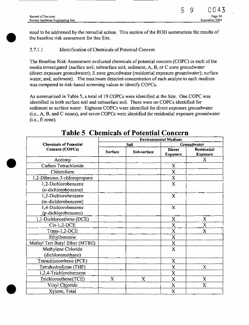
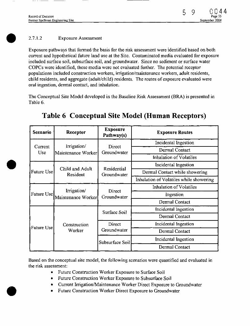
. 2.7.1.1 Identification of Chemicals of Potential Concern 342.7.1.2 Exposure Assessment 352.7.1.3 Toxicity Assessment 362.7.1.4 Risk Characterization 362.7.1.5 Uncertainties 38
5 9 0 0 0 4Record of Decision Page iiFormer Spellman Engineering Site September 2004
2.9 Remedial Alternatives 402.9.1 Description of Remedial Alternatives Evaluated 40
2.9.1.1 Source Groundwater Alternatives 402.9.1.2 Highly Impacted Zone Groundwater Alternatives 452.9.1.3 Dilute Groundwater Plume Alternative 50
2.9.2 Common Elements and Distinguishing Features of EachAlternative 55
2.9.3 Expected Outcomes of Each Alternative 562.9.3.1 Source Groundwater Alternatives 562.9.3.2 Highly Impacted Groundwater Alternatives 572.9.3.3 Dilute Groundwater Plume Alternatives 57
2.10 Comparative Analysis of Alternatives 572.10.1 Overall Protection of Human Health and the Environment 58
2.10.1.1 Source Zone 582.10.1.2 Highly Impacted Groundwater Zone 582.10.1.3 Dilute Groundwater Zone 59
2.10.2 Compliance with Applicable or Relevant and AppropriateRequirements 592.10.2.1 Source Zone ARARs 602.10.2.2 Highly Impacted Zone ARARs 612.10.2.3 Dilute Groundwater Plume ARARs 61
2.10.3 Long-Term Effectiveness and Permanence 622.10.3.1 Source Zone 622.10.3.2 Highly Impacted Zone 622.10.3.3 Dilute Zone 63
2.10.4 Reduction of Toxicity, Mobility, or Volume Through Treatment 632.10.4.1 Source Zone 642.10.4.2 Highly Impacted Zone HIGS3 and HIGS4 642.10.4.3 Dilute Zone 64
2.10.5 Short-Term Effectiveness 652.10.5.1 Source Zone 652.10.5.2 Highly Impacted Zone 662.10.5.3 Dilute Zone 66
2.10.6 Implementability 662.10.6.1 Source Zone 672.10.6.2 Highly Impacted Zone 672.10.6.3 Dilute Zone 67
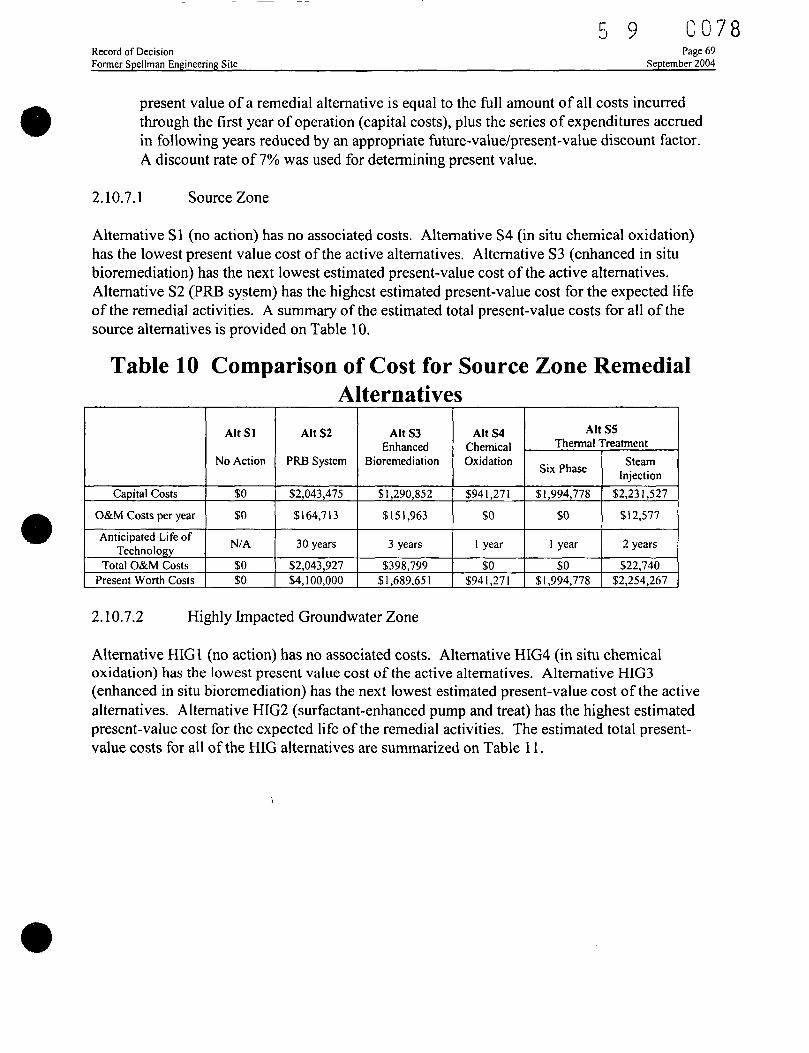
2.10.7 Cost 672.10.7.1 Source Zone 692.10.7.2 Highly Impacted Groundwater Zone 692.10.7.3 Dilute Groundwater Plume Zone 70
2.10.8 State/Support Agency Acceptance 702.10.9 Community Acceptance 70
2.11 Principal Threat Wastes 712.12 Selected Remedy 71
2.12.1 Summary of the Rationale for the Selected Remedy 712.12.1.1 Source Groundwater 71
5 9 0 0 0 5Record of Decision Page iiiFormer Spellman Engineering Site September 2004
2.13.1 Protection of Human Health and the Environment 812.13.2 Compliance with ARARs 812.13.3 Cost Effectiveness 822.13.4 Permanent and Alternative Treatment Solutions 832.13.5 Preference for Treatment as a Principal Element 832.13.6 Five-Year Review Requirement 83
5 9 C 0 0 6Record of Decision *-* ' Page ivFormer Spellman Engineering Site September 2004
LIST OF FIGURESFigure 1 Location of OUC Production Wells 16Figure 2 Cross-Section Traverses 19Figure 3 Lithologic Cross-Section A - A' 20Figure 4 Lithologic Cross-Section B - B' 21Figure 5 Lithologic Cross-Section C - C' 22Figure 6 Process Flow Diagram for Enhanced In Situ Bioremediation 42Figure 7 Surfactant Enhanced Pump and Treat 47
LIST OF PHOTOGRAPHSPhotograph 1 Former Spellman Engineering Property and Area Where Release Occurred 3Photograph 2 View of OUC Property from Former Spellman Engineering Property 4Photograph 3 Lake Highland Preparatory School Sports Complex 5Photograph 4 Parking Lot with Area of Highest TCE Contamination 6Photograph 5 Installation of Permanent Monitoring Well on OUC Property 10Photograph 6 City Commissioner and EPA Representative at June 16, 2004 Public Meeting... 13
LIST OF PLATESPlate 1 USGS Vicinity Map 96Plate 2 Site Map 97Plate 3 Contaminant Source Area 98Plate 4 Conceptual Model 99Plate 5 TCE Plume Migration Model 100Plate 6 Clay Elevation Contour Map 102Plate 7 TCE Isoconcentration Contours - A Zone 103Plate 8 TCE Isoconcentration Contours - B Zone 104Plate 9 TCE Isoconcentration Contours - C Zone 105Plate 10 TCE Isoconcentration Contours-E Zone 106Plate 11 Plume Area Limits 107
LIST OF TABLESTable 1 OUC Production Wells 16Table 2 Estimated Volume of TCE 30Table 3 OUC Production Wells 32Table 4 Potable Well Survey 33Table 5 Chemicals of Potential Concern 34Table 6 Conceptual Site Model (Human Receptors) 35Table 7 Summary of Elevated Aggregate Risks Identified 37Table 8 Groundwater Cleanup Goals 40Table 9 Remedial Alternatives 55Table 10 Comparison of Cost for Source Zone Remedial Alternatives 69Table 11 Comparison of Cost for Highly Impacted Groundwater Zone Remedial Alternatives. 70Table 12 Comparison of Cost for Dilute Zone Remedial Alternatives 70
5 9 oqo?Record of Decision '-' ' PagevFormer Spellman Engineering Site September 2004
Table 13 Summary of Remediation Costs 74Table 14 Cost Estimate for Source Alternative S4 Surfactant-Enhanced In Situ Chemical
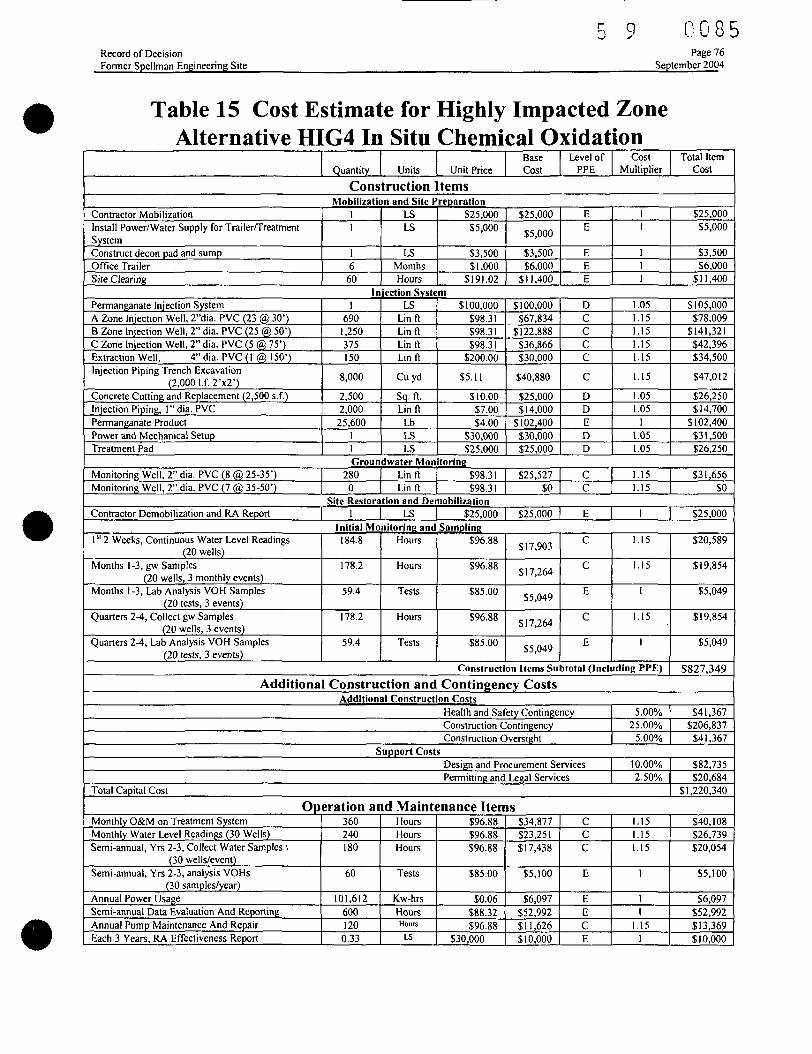
Oxidation 75Table 15 Cost Estimate for Highly Impacted Zone Alternative HIG4 In Situ Chemical
Oxidation 76Table 16 Cost Estimate for Dilute Groundwater Plume Alternative GW4 Bioremediation-
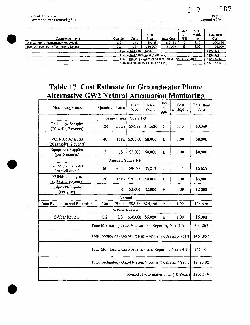
Carbohydrate Injection 77Table 17 Cost Estimate for Groundwater Plume Alternative GW2 Natural Attenuation
Monitoring 78Table 18 Final Groundwater Cleanup Levels 79Table 19 Summary of Contaminant-Specific ARARs Former Spellman Engineering Site 81Table 20 Summary of Location-Specific ARARs Former Spellman Engineering Site 82Table 21 Summary of Action-Specific ARARs Former Spellman Engineering Site 82
Record of DecisionFormer Spellman Engineering Site
5 9 GOJSeptember 2004
LIST OF ACRONYMS AND ABBREVIATIONS
ARAR Applicable or Relevant and Appropriate RequirementBGS Below Ground SurfaceBLS Below Land SurfaceBOD Biological Oxygen DemandBRA Baseline Risk AssessmentCAR Contamination Assessment ReportCERCLA Comprehensive Environmental Response, Compensation, Liability Act of 1980CFR Code of Federal Regulationsthe City City of OrlandoCOC Contaminant of ConcernCOD Chemical Oxygen DemandCOPC Contaminant of Potential ConcernDCE DichloroetheneDNAPL Dense Non-Aqueous Phase LiquidEPA U.S. Environmental Protection AgencyFAC Florida Administrative CodeFDEP Florida Department of Environmental ProtectionFLUTe Flexible Liner Underground Technologies, Ltd.FS Feasibility StudyGCTL Groundwater Cleanup Target Levelgpd gallons per daygpm gallons per minuteHI Hazard IndexHQ Hazard QuotientIT Corp International Technology CorporationMCLG Maximum Contaminant Level Goalmg/1 Milligrams per literHg/kg Micrograms per kilogramjag/1 Micrograms per literMGD Million Gallons per DayMNA Monitored Natural AttenuationMSL Mean Sea LevelMW Monitoring WellNASA National Aeronautics and Space AdministrationNCP National Contingency PlanNGVD National Geodetic Vertical DatumNPDES National Pollutant Discharge Elimination SystemNPL National Priorities ListNRIS National Register Information SystemO&M Operation and MaintenanceOSHA Occupational Safety and Health AdministrationORP Oxidation-Reduction PotentialOUC Orlando Utilities Commission
5 9 C 0 0 9Record of Decision Page viiFormer Spellman Engineering Site September 2004
LIST OF ACRONYMS and ABBREVIATIONS(Continued)PCE Tetrachloroethene or PerchloroethenePSI Professional Service Industries, Inc.PRB Permeable Reactive BarrierRAGS Risk Assessment Guidance for SuperfundRAO Remedial Action ObjectiveRBC Risk-Based ConcentrationRCRA Resource Conservation and Recovery ActRI Remedial InvestigationROD Record Of DecisionSARA Superfund Amendments and Reauthorization ActSCTL Soil Cleanup Target LevelSVOC Semi-Volatile Organic CompoundTCE TrichloroetheneUSC United States CodeUSGS United States Geological SurveyVC Vinyl ChlorideVOC Volatile Organic CompoundVPAC Vapor Phase Activated CarbonWT Water Table
5 9 0 0 1 0Record of Decision Page 1Former Spellman Engineering Site September 2004
PARTI: THE DECLARATION
1.1 Site Name and Location
This Record of Decision (ROD) is for the former Spellman Engineering site, which is located at722 Brookhaven Drive and is situated between Lake Highland, Lake Ivanhoe, and Lake Formosa,near the commercial district of Orlando, Florida. The U.S. Environmental Protection Agency(EPA) Site Identification Number is FL00002264810.
1.2 Statement of Basis and Purpose
This decision document presents the Selected Remedy for the former Spellman Engineering site(the "Site"), which was chosen in accordance with the Comprehensive Environmental Response,Compensation, and Liability Act of 1980 (CERCLA), as amended by the SuperfundAmendments and Reauthorization Act of 1986 (SARA), and, to the extent practicable, theNational Contingency Plan (NCP). This decision is based on the Administrative Record forthe Site. The State of Florida has participated in the Remedial Investigation/ Feasibility Studyprocess and in the selection of the remedy, and, though formal concurrence has not yet beenreceived, EPA anticipates concurrence with this decision.
1.3 Assessment of Site
The response action selected in this Record of Decision is necessary to protect the public healthor welfare and the environment from actual or threatened releases of hazardous substances to theenvironment.
1.4 Description of Selected Remedy
The overall cleanup strategy for this Site is to meet the Remedial Action Objectives (RAO) byeliminating or reducing contamination in groundwater to below applicable standards (Federal andState maximum contaminant levels) and human-health risk-based criteria. The selected remedyremoves the source materials constituting principal threats at the site. The major components forthe Selected Remedy include:
a Surfactant enhanced in situ chemical oxidation of the source area (Trichloroethene (TCE)>100,000 micrograms per liter (|ag/l)) and in situ chemical oxidation of the highly-impacted zone (100,000 ng/1 > TCE > 10,000 jag/1) followed by performance monitoring,and addressing vadose zone soils exceeding leachability criteria, if identified;
a Enhanced in situ bioremediation of groundwater with TCE concentrations greater than2,000 ug/1 and partial enhanced in situ bioremediation of groundwater with TCEconcentrations greater than 300 ug/1 followed by performance monitoring;
a Natural attenuation monitoring until cleanup goals are met;a Engineering controls to protect injection and monitoring points from damage or public
access;a Institutional controls to restrict groundwater use until cleanup goals are met; anda Five-year reviews of the remedy until cleanup goals are met.
5 9 0011Record of Decision Page 2Former Spellman Engineering Site September 2004
1.5 Statutory Determinations
The Selected Remedy is protective of human health and the environment, complies with Federaland State requirements that are legally applicable or relevant and appropriate to the remedialaction (unless justified by a waiver), and is cost effective. This remedy utilizes permanentsolutions and alternative treatment technologies to the maximum extent practicable for this Siteand satisfies the statutory preference for remedies that employ treatment that reduces toxicily,mobility, or volume as a principal element.
This remedy will not result in hazardous substances, pollutants, or contaminants remaining on-site above levels that allow for unl imi ted use and unrestricted exposure, but it wi l l take more thanfive years to attain remedial action objectives and cleanup levels. Therefore, policy reviews willbe conducted at least every five years after the initiation of remedial action for the site to ensurethat the remedy is, or wil l be, protective of human health and the environment
1.6 Data Certification Checklist
The following information is included in the Decision Summary Section of this Record ofDecision (Part 2). Additional information can be found in the Administrative Record file for thisSite.
a Chemicals of concern and their respective concentrationsa Baseline risk represented by the chemicals of concerna Cleanup levels established for chemicals of concern and the basis for these
levelsa How source materials constituting principal threats are addresseda Current and reasonably anticipated future land use assumptions and current
and potential future beneficial uses of groundwater used in the Baseline RiskAssessment and Record of Decision
a Potential land and groundwater uses that wi l l be available at the Site as aresult of the Selected Remedy
a Estimated capital, annual operation and maintenance (O&M), and total presentworth costs, discount rate, and the number of years over which the remedycost estimates are projected
a Key factor(s) that led to selecting the remedy (i.e describe how the SelectedRemedy provides the best balance of tradeoffs with respect to the balancingand modifying criteria, highlighting criteria key to the decision)
1.7 Authorizing Signature
Winston A. Smith DateDirectorWaste Management Division
5 9 0012Record of DecisionFormer Spellman Engineering Site
Page 3September 2004
PART 2: THE DECISION SUMMARY
2.1 Site Name, Location, and Brief Description
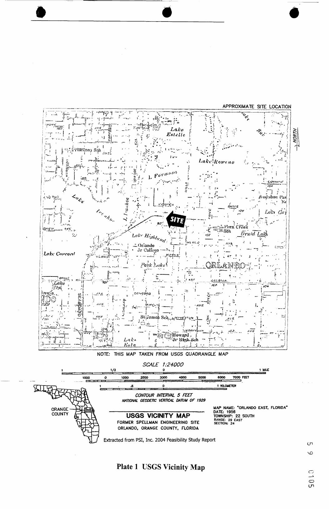
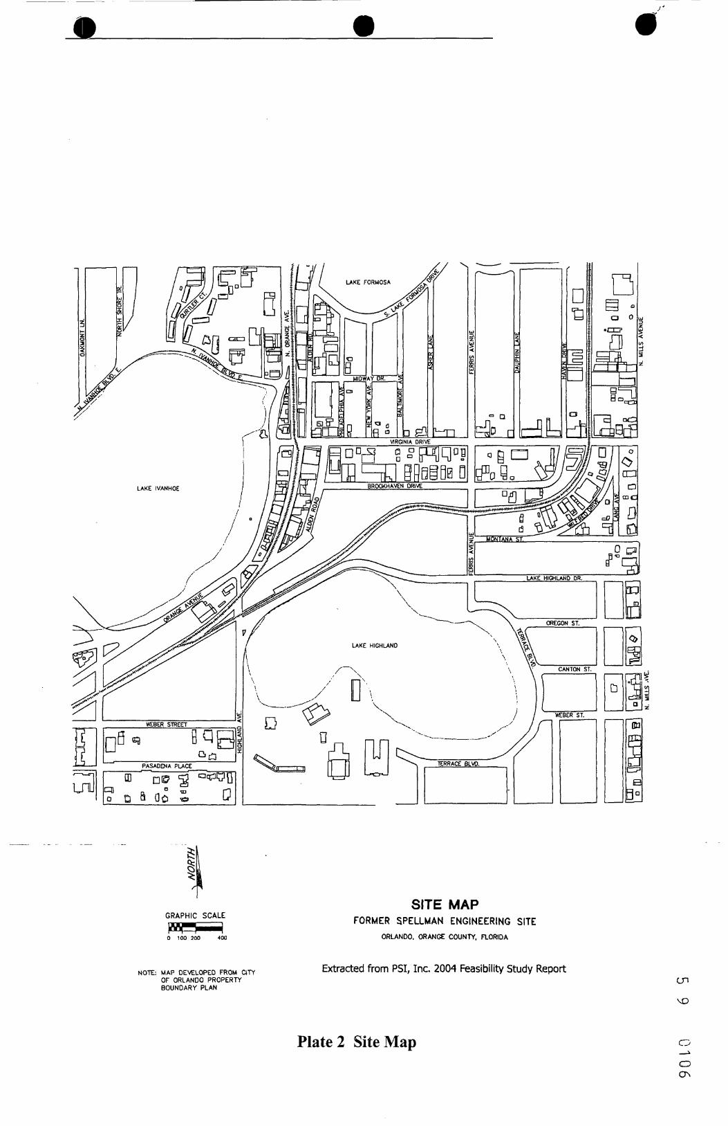
This Record of Decision (ROD) is for the Former Spellman Engineering site, which is located at722 Brookhaven Drive, northeast of Lake Highland in Orlando, Orange County, Florida. AUnited States Geological Survey (USGS) vicinity map is shown on Plate 1 and a site map isshown on Plate 2. The United States EPA Site Identification Number is FL00002264810. Thelead agency for this Site is the EPA.
The study area, referred to as the "Site", encompasses light industrial, commercial, andresidential properties and includes the former OUC (Orlando Utilities Commission)maintenance facility and the former Spellman Engineering property. The former SpellmanEngineering property is currently occupied by an unrelated business. Photograph 1 represents aportion of the former Spellman Engineering property and the parking area where the assumedrelease occurred.
Photograph 1 Former Spellman Engineering Property andArea Where Release Occurred
Record of DecisionFormer Spellman Engineering Site
5 9 C 0 1 3Page 4
September 2004
The former Spellman Engineering property is approximately 100 feet by 160 feet in size. Theformer OUC maintenance property, located at 601 Lake Highland Drive, is approximately 25acres in size (Photograph 2). The eastern half of the former OUC maintenance property issecured with a chain link fence and is currently used as a parking area for OUC vehicles. Thebuildings and other structures previously located on the former OUC maintenance property havebeen demolished and removed.
Photograph 2 View of OUC Property from FormerSpellman Engineering Property
The surrounding properties are light industrial and commercial operations, with residential areasto the north, south, and east. Other facilities within the study area include an automotive repairshop, several printing companies, a medical clinic, three older dry cleaning facilities, a cartonfinishing business, a construction company, and a residential neighborhood. A CSXCorporation railroad track transects the center of the study area in an east-west direction, and isadjacent to the south side of the former Spellman Engineering property. A dry-cleaning plantopened for business approximately 500 feet east of the intersection of Ferris Avenue andBrookhaven Drive, across the street from the former Spellman Engineering property, in thespring of 2002. In the summer of 2002, the western portion of the former OUC maintenanceproperty was leased to the Lake Highland Preparatory School for development as a recreationalarea. Construction on the recreational area, including a baseball diamond and tennis courts, hassince been completed and is shown on Photograph 3.
5 9 C 0 1 4Record of DecisionFormer Spellman Engineering Site
Page5September 2004
Photograph 3 Lake Highland Preparatory School SportsComplex
2.2 Site History and Enforcement Activities
2.2.1 Activities that Lead to Current Problem
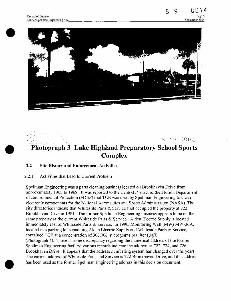
Spellman Engineering was a parts cleaning business located on Brookhaven Drive fromapproximately 1963 to 1969. It was reported to the Central District of the Florida Departmentof Environmental Protection (FDEP) that TCE was used by Spellman Engineering to cleanelectronic components for the National Aeronautics and Space Administration (NASA). Thecity directories indicate that Whiteside Parts & Service first occupied the property at 722Brookhaven Drive in 1981. The former Spellman Engineering business appears to be on thesame property as the current Whiteside Parts & Service. Alden Electric Supply is locatedimmediately east of Whiteside Parts & Service. In 1996, Monitoring Well (MW) MW-36A,located in a parking lot separating Alden Electric Supply and Whiteside Parts & Service,contained TCE at a concentration of 300,000 micrograms per liter (ng/1)(Photograph 4). There is some discrepancy regarding the numerical address of the formerSpellman Engineering facility; various records indicate the address as 722, 724, and 726Brookhaven Drive. It appears that the address numbering system has changed over the years.The current address of Whiteside Parts and Service is 722 Brookhaven Drive, and this addresshas been used as the former Spellman Engineering address in this decision document.
5 9 0 0 1 5Record of DecisionFormer Spellman Engineering Site
Page 6September 2004
r~
Photograph 4 Parking Lot with Area of Highest TCEContamination
No records were available that described site operations at the former Spellman Engineeringsite. The owner, Mr. Spellman, stated that the parts cleaning activities were accomplishedutilizing Triclene, a common degreasing solvent, which is also known as TCE. According to aresident in the vicinity of the property (personal communication between FDEP, ProfessionalService Industries, Inc. (PSI), and Whiteside Parts and Service owner, Jack Myles), the partscleaning occurred in the south portion of the property just north of the railroad tracks. Mr.Myles also indicated that waste solvent was stored in drums that were emptied in the vicinity ofthe parts cleaning area prior to pick up by a Triclene vendor. Typical parts cleaning processesincluded either spray washers or dipping vessels. Sanborn maps indicated an enclosed area inthe southeastern portion of the former Spellman Engineering site that coincides with the highestlevels of TCE in the soil gas and in the groundwater.
The former Spellman Engineering property is currently being used by Whiteside Parts & Serviceand a silk floral business. The area of highest detected groundwater contaminantconcentrations, and the only area with detectable soil contamination, is the current parking areabetween Alden Electric supply,and the flower shop.
Record of Decision 0 7Former Spellman Engineering Site September 2004
The former OUC maintenance facility, at 601 Lake Highland Drive, was used for equipmentstorage, vehicle maintenance, and fleet parking since the mid 1950s through 1993. The formerOUC maintenance facility is also reported to have stored piping, power poles, and transformersnecessary for the maintenance of water and power distribution systems. The site previouslymaintained a total of 14 fuel tanks (removed in 1993), most of which dispensed diesel orgasoline. Two aboveground storage tanks (ASTs) contained kerosene and mineral spirits usedfor equipment maintenance.
The eastern portion of the former OUC maintenance facility is currently vacant and is beingutilized as a parking area for OUC vehicles. All previous buildings have been demolished.Lake Highland Preparatory School currently utilizes the western portion of the former OUCmaintenance facility as sports complex that includes a tennis courts, a soccer field, and abaseball diamond. The specific location of the recreational facility is north of the railroad tracksand encompasses the comer of Alden Road and Brookhaven Drive.
2.2.2 Previous Investigations
Several site studies have been submitted to EPA Region IV, FDEP Central District, and FDEPTallahassee, Bureau of Waste Cleanup for review as follows:
• Risk Assessment, Hazardous Substance & Waste Management Research, Inc. (HSWMR)through International Technology Corporation (IT Corp) for OUC in 1992;
• Contamination Assessment Report (CAR), IT Corp for OUC, August 27,1993;• Revised Contamination Assessment, PSI for FDEP, February 12, 1997;• Supplemental Contamination Assessment, PSI for FDEP, the City, OUC, September 9,
1998;• Revised Work Plan for Additional Assessment, PSI for the City and OUC, September 30,
1999;• RI Work Plan, PSI for EPA, the City and OUC, March 2001;• Remedial Investigation Report, PSI for EPA, the City and OUC, September 2003;• Baseline Risk Assessment, HSWMR for the City and OUC, April 2004 and;• Feasibility Study Report, PSI for EPA, the City and OUC, May 2004.
Risk Assessment, Hazardous Substance & Waste Management Research, Inc. (HSWMR)through IT Corp for OUC in 1992
An initial Risk Assessment was performed that consisted of an evaluation of soil, sediment andgroundwater sampling results from the initial investigations to evaluate the present and futurehealth effects related to the use of the formerOUC maintenance facility. The Risk Assessmentconcluded that the site conditions did not pose an imminent threat to the health, safety, andwelfare of the public or the environment.
5 9 C 0 1 7Record o f Dec i s ion Page 8Former Spellman Engineering Site September 2004
Contamination Assessment Report. IT Corp for OUC. August 27, 1993/
TCE was originally detected in the groundwater in the study area in 1992 during a petroleum-related Contamination Assessment performed at the former OUC maintenance facility. Theassessment was performed to address petroleum contamination with a subsequent sourceremoval of 2,318 tons of petroleum-contaminated soil originating from the tank systemscontaining mineral spirits, hydraulic fluid, waste oil sludge, and diesel fuel. The contaminatedsoil was removed from the former OUC maintenance facility and transported for processing atpermitted facilities in Florida. IT Corp performed the petroleum assessment and remediation onbehalf of OUC.
IT Corp also performed a study to delineate the TCE groundwater contamination within theformer OUC maintenance facility property boundaries. The results of the assessment werepresented in a 1993 Contamination Assessment Report (CAR), which concluded that a dissolvedTCE groundwater plume extended broadly along the northern edge of the former OUCmaintenance property and was migrating in a southwesterly direction toward Lake Highland.
The CAR also concluded that TCE degradation products, i.e. dichloroethene (DCE) and vinylchloride (VC), were not present in the groundwater at that time at significant concentrations dueto a lack of biological activity. Based upon information gathered on the characteristics of theplume, the report concluded that the TCE contamination originated from a source or sourcesupgradient and off-site, and that the plume might be migrating along the sewer line that runseast-west off of Brookhaven Drive.
Revised Contamination Assessment, PSI for FDEP, February 12. 1997
PSI was retained by the FDEP Site Investigation Section to evaluate potential sources ofcontamination in the Lake Highland area. In 1996, PSI initiated a site investigation byreviewing available historic records and contamination assessments performed in the study area,and by implementing an invasive testing program to determine the TCE source. Numeroustesting techniques were employed including passive and active soil gas, lithologic evaluation,monitoring well installation, laboratory analyses of groundwater, and sewer line sampling.
A potential source area had been tentatively located northeast of the former OUC maintenancefacility, with potential secondary source areas located along the sanitary sewer line or at aproperty located along Brookhaven Drive. The area encompassed an older neighborhood thathad been occupied by commercial and light industrial businesses along Brookhaven Drive,many of which may have used TCE in their operations. PSI conducted a passive soil gas surveyto the north and east of the OUC property in an effort to identify the source of TCE. Thesanitary sewer system was also tested for the presence of TCE. The former SpellmanEngineering property was identified in city directory research as a possible TCE source, due toits former operation as a parts cleaning facility. In subsequent interviews by the FDEP and PSIwith the current owner of the former Spellman Engineering property, it was stated that TCE hadbeen utilized and discarded near the rear of the former Spellman Engineering building, in closeproximity to the railroad corridor. Results of PSI's passive gas sampling survey subsequently
5 9 0018Record of Decision Page 9Former Spellman Engineering Site September 2004
confirmed that the highest levels of chlorinated solvents in soil gas were present at the formerSpellman Engineering property.
A monitoring well network was then designed by PSI to augment wells previously installed inthe neighborhood by IT Corp and others. Groundwater samples collected from shallowmonitoring wells on the former OUC maintenance property, as well as the two shallow wells at611/615 Brookhaven Drive, previously evaluated as a potential source area, were belowdetection levels for chlorinated solvent compounds when re-sampled. The highestconcentrations were detected in two newly installed shallow wells on the former SpellmanEngineering property. In addition to the groundwater quality testing program, an active soil gassurvey was conducted on the former OUC maintenance property and the 611/615 BrookhavenDrive property. The results indicated very low levels of solvent compounds in the northeastcorner of the former OUC maintenance property, and none at 611/615 Brookhaven Drive.Similarly, subsequent soil analytical sampling at these locations indicated that no chlorinatedsolvent compounds were detected in the soil collected. Whereas, at the former SpellmanEngineering facility, relatively elevated levels of chlorinated solvents were detected in the soilgas and soil samples. Therefore, the former Spellman Engineering property(722-726 Brookhaven Drive) was determined to be the most likely source of the groundwatercontaminant plume in the Lake Highland Drive area. The contaminant source area is identifiedon Plate 3.
Supplemental Contamination Assessment, PSI for FDEP, the City. OUC. September 9. 1998
PSI continued the assessment of the Site for the FDEP Site Investigation Section, the OUC, andthe City to evaluate the horizontal and vertical extent of the TCE groundwater contaminantplume. A Supplemental Contamination Assessment was performed in 1998 utilizing percussionprobe techniques (i.e. Geoprobe™) and the installation of additional permanent monitoring wells(see Photograph 5).
The results of the assessment activities indicated that the TCE contaminant plume appeared tohave migrated from the source area in a predominantly western direction along the top of a clayto clayey sand unit and terminated just east of Orange Avenue, near Lake Ivanhoe. The resultsfurther indicated that the TCE contaminant plume had penetrated the clay/clayey sand layer andwas migrating down through the clay unit as it moved in a horizontal downgradient flowdirection. The contamination in this zone did not originally appear to be as laterally extensiveas the TCE contamination present above the clay layer, and was thought to terminate near theintersection of Lake Highland Drive and Highland Avenue, just south of Orange Avenue. Thegreatest depth tested for TCE prior to 2001 was between 60 to 72 feet below land surface (BLS).Moderate concentrations of TCE were detected at the 55 feet depth interval within the center ofthe contaminant plume. The vertical extent of the TCE contamination within the center of theplume was not defined during the Supplemental Contamination Assessment.
5 9 C 0 1 9Record of DecisionFormer Spellman Engineering Site
Page 10September 2004
Photograph 5 Installation of Permanent Monitoring Wellon OUC Property
Remedial Investigation Report. PSI for EPA, the City, and OUC. September 2003
PSI continued investigation of the former Spellman Engineering site for the EPA, the OUC, andthe City to complete evaluation of the extent of contamination in all potentially impacted media.A focus of the Remedial Investigation was to define the horizontal and vertical extent of the
TCE groundwater contaminant plume. In addition to the groundwater assessment, surface waterand sediment in Lake Highland was sampled and analyzed for contamination, the hydraulicproperties of the aquifers were tested, the 'source area' was investigated for dense non-aqueousphase liquid (DNAPL), grain size and geotechnical analysis was performed on soil samples, andgroundwater samples were analyzed for natural attenuation parameters. This data collectionalso was designed to support development of a baseline risk assessment and feasibility study toallow for selection of a remedy.
5 9 0 0 2 0Record of Decision Page 11Former Spellman Engineering Site September 2004
The results of the Remedial Investigation confirmed that the TCE groundwater contaminantplume has migrated from the source area at the former Spellman Engineering property in apredominantly western direction along the top of a clay to clayey sand unit. The TCEcontaminant plume had penetrated this layer and was migrating downward as it moved in thehorizontal downgradient flow direction. The groundwater contaminated with TCE and itsrelated degradation products extended from the source area of approximately 40 acres to LakeHighland in the south, to near Lake Ivanhoe in the west, and toward Lake Formosa in the north.Contamination also had migrated vertically through different lithologic units reaching a depth
of approximately 115 feet below ground surface (BGS) near Lake Highland, but contaminationhad not reached the upper Floridan aquifer.
The Remedial Investigation also determined that contaminant impacts to vadose zone(unsaturated) soils were limited in both magnitude and extent primarily due to the high volatilityand density of TCE, the apparently limited area of release, and the age of the release. DNAPLinvestigation in the source area did not identify the presence of free-phase TCE despitegroundwater contaminant concentrations indicating its likely presence at the Site. Geotechnicaland hydraulic testing indicated a wide range of hydraulic conductivities in the water-bearingunits at the Site, ranging from less than one-tenth of a foot per day to more than 140 feet perday. Surface water samples from Lake Highland indicated that trace amounts of TCE werepresent in the lake, and sediment samples from the adjacent lake bottom confirmed that TCEhad reached Lake Highland.
Baseline Risk Assessment. HSWMR for the City and OUC. April 2004
A Baseline Risk Assessment was prepared for the EPA, OUC, and the City to determine thecurrent and future effects of the Site contaminants in all media on human health. Based onscreening of maximum detected concentrations, 19 chemicals of potential concern wereidentified and these were further evaluated for both current and future risk exposure associatedwith usage as residential and occupational exposure pathways. No potentially unacceptable riskwas identified for soil, sediment, or surface water impacted by Site contaminants. Potentiallyunacceptable risk was identified for five chemicals in groundwater for both occupational(current and future risk) and residential (future risk) scenarios. Ecological risk was not formallyassessed since contaminants of concern were only found in soil and groundwater, and completeexposure pathways to ecological receptors from these media were not considered to be present.Potentially impacted Site soils are isolated from the environment by pavement, and groundwateris not a media of potential ecological concern except at the point of discharge to Lake Highland.Contaminant concentrations in surface water and sediment in Lake Highland were not found at
levels of concern.
5 9 . 0 0 2 1Record of Decision Page 12Former Spellman Engineering Site September 2004
Feasibility Study Report. PSI for EPA, the City and OUC. May 2004
A Feasibility Study Report was prepared by PSI for EPA, OUC, and the City to develop cleanupalternatives for groundwater contamination at the Site, to screen the different alternativesagainst established criteria, and to provide a comparative analysis of the viable remedialalternatives. The feasibility study segregated the chlorinated solvent plume into three differentzones based upon groundwater concentrations. The source zone included portions of thegroundwater plume where the TCE concentration is greater than 100,000 ug/1, the highlyimpacted zone included portions of the groundwater plume where the TCE concentration isbetween 10,000 ug/1 and 100,000 u.g/1, and the dilute groundwater plume area is where the TCEconcentration is less than 10,000 ug/1.
Several different remedial alternatives were evaluated for each of the three contaminant zones.The remedial alternatives were evaluated based on the nine criteria set forth in the NCPThese include threshold criteria (overall protection of human health and the environment, andcompliance with applicable or relevant and appropriate requirements(ARAR), ARAR balancingcriteria (implementability, short-term effectiveness, long-term effectiveness and permanence,and reduction of toxicity, mobility, or volume by treatment), and modifying criteria (Stateacceptance and community acceptance). The alternatives that met the threshold criteria andbest met the balancing criteria were identified, and considerations relative to combining thevarious alternatives also were addressed.
2.3 Community Participation
EPA, in conjunction with the City and OUC, has conducted community relations activitiesthroughout the remedial investigation process. Community outreach activities have includedattendance at public availability sessions, issuance of Fact Sheets during the investigativeprocess, publication of public notices in the Orlando Sentinel newspaper, and maintaining theInformation Repository at the Orlando Public Library.
In support of the remedial alternative selection process, a public availability session was held inOrlando, Florida on June 16, 2004 to present the results of the remedial investigation andbaseline risk assessment (Photograph 6). At this meeting, the remedy selection and decisionprocess was discussed with the community, and the mailing list for the Site was updated. FactSheet Updates also were distributed to the community at the public meeting summarizing thefindings of the investigation and risk assessment.
The Proposed Plan Fact Sheet was made available to the community on July 23, 2004. A copyof the Administrative Record is available to the public at the information repository maintainedat the EPA Region 4 Superfund Record Center and at the Orange County Public Library at 101East Central Boulevard, Orlando, Florida. The notice of the availability of the AdministrativeRecord and an announcement of the Proposed Plan public meeting was published in thenewspaper on August 5, 2004. A public comment period was held from July 23, 2004 toAugust 27, 2004, and a public meeting to solicit community input to the Proposed Plan was held
5 9 0 0 2 2Record of DecisionFormer Spellman Engineering Site
Page 13September 2004
Photograph 6 City Commissioner and EPA Representativeat June 16, 2004 Public Meeting
on August 12, 2004 at the Lake Highland Preparatory School. At this meeting, representativesfrom EPA presented the preferred remedial alternative for the Site, and received publiccomments on the Proposed Plan. EPA's response to the comments received during the publiccomment period is included in the Responsiveness Summary, located in Part 3 of this ROD.The transcript from the public meeting can be found in the Administrative Record for this Site.
2.4 Scope and Role of Operable Unit or Response Action
EPA has chosen to use one Operable Unit for this Site. The remedy will address groundwaterand associated media, including vadose zone soils exceeding teachability criteria, contaminatedwith elevated levels of volatile organic compounds (VOC), primarily TCE. The selectedtreatment methods vary depending on the magnitude of contamination, and are presented indetail in Section 2.12 of this ROD. This action will reduce or eliminate the risks to human andecological receptors, and will result in full restoration of these resources for unrestricted use andunlimited exposure.
2.5 Site Characteristics
2.5.1 Conceptual Site Model
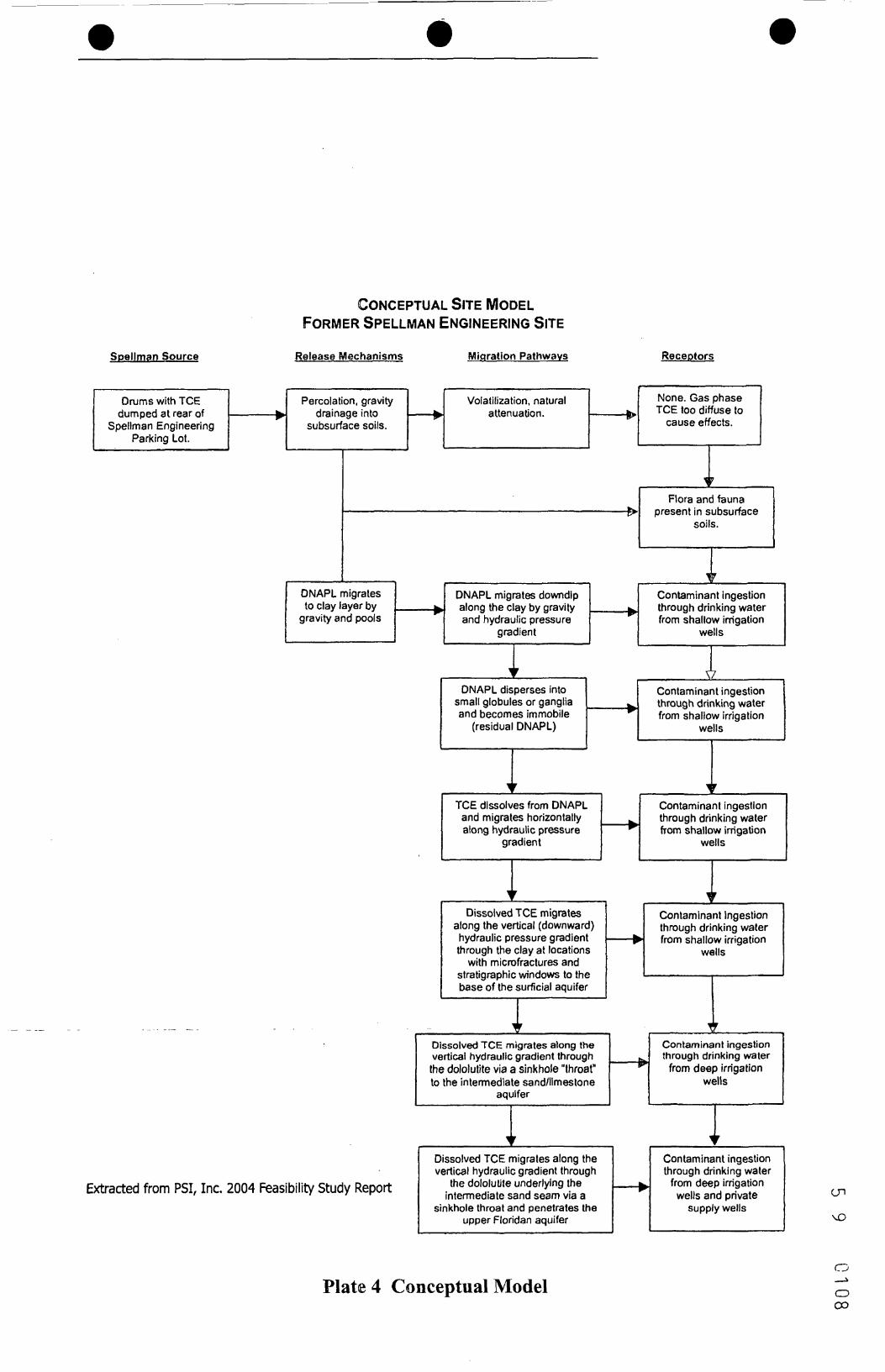
The following conceptual model describes the mechanisms of the TCE release, migration in thesubsurface, and pathways to potential receptors. A summary of the conceptual model isprovided as Plate 4, and a visual representation of the migration of TCE in the groundwater isprovided on Plate 5.
The components of the conceptual model are described below:
5 9 0023Record of Decision Page 14Former Spellman Engineering Site September 2004
• The former Spellman Engineering facility parking lot has been identified as the entrypoint for the TCE soil and groundwater contamination;
• The release of TCE appears to have occurred in the 1960s, a time period during whichSpellman Engineering cleaned parts with TCE;
• Release mechanisms at the site include gravity drainage and rainfall percolation;
• Very little vadose soil contamination exists at the site. TCE in soil appears to have forthe most part volatilized, migrated to the water table, or degraded through other naturalattenuation processes;
• Most of the TCE contaminant mass at the site remains in the saturated zone source areaand continues to dissolve from potential residual DNAPL and sorbed contaminants;
• Dissolved TCE is migrating toward the area lakes: Lake Highland, Lake Ivanhoe, andLake Formosa, with the most significant migration pathway towards Lake Highland;
• Dissolved TCE begins to appear beneath the clay near the southwest quadrant of theintersection of Brookhaven Drive and Ferris Avenue and descends in stair step fashiontowards Lake Highland. TCE is also migrating below the clay to a lesser extent towardsLake Ivanhoe and Lake Formosa;
• TCE penetrates the clay semi-confining layer where stratigraphic windows and/ormicrofractures are present. TCE then migrates to deeper hydrogeologic zones bydownward advection along the vertical hydraulic gradient;
• The clay layer that defines the boundary between the A and B Zones bends upward at thesouthwest quadrant of Brookhaven Drive and Ferris Avenue. This location may havestratigraphic windows and/or microfractures due to stress from upwarping, thus acting asan entry point for downward migrating TCE;
• Dissolved TCE continues to migrate vertically below Lake Highland, potentially withina paleo-sinkhole present in the subsurface, into an intermediate aquifer in the lowerportion of the Arcadia Formation of the Hawthorne Group;
• TCE contaminated groundwater has reached Lake Highland, a discharge point forgroundwater originating at the Site;
• The potential for TCE to migrate deeper into the upper Floridan aquifer has not beenfully evaluated due to the presence of Lake Highland. Based upon the TCEconcentrations detected in the intermediate aquifer in the E Zone and the absence of TCEin upper Floridan monitoring wells, TCE concentrations entering the upper Floridan
5 9 C 0 2 4Record of Decision Page 15Former Spellman Engineering Site September 2004
aquifer are expected to be very low and would likely be significantly diluted by the highflow within this aquifer;
• Due to the thick dololutite layer encountered at the site and the significant dilutioneffects resulting from high flow, it is unlikely that the TCE concentrations detected at thesite have impacted the Lower Floridan aquifer or OUC's water production wells locatedin the vicinity of the study area; and,
• The TCE groundwater contaminant plume originating from the former SpellmanEngineering property will continue to contaminate the surficial aquifer and theHawthorne Group intermediate aquifer until remediated. Under current conditions,contaminant concentrations at potential exposure points (Lake Highland and watersupply wells) would be expected to remain the same or increase for a protracted periodof time.
2.5.2 Site Overview
The study area, referred to as the "Site", encompasses light industrial, commercial, andresidential properties and includes the former OUC maintenance property and the formerSpellman Engineering property. Located northeast of Lake Highland the former SpellmanEngineering property, at 722 Brookhaven Drive, is currently occupied by Whiteside Parts andService. The Spellman property is approximately 100 feet by 160 feet in size. The former OUCmaintenance property, located at 601 Lake Highland Drive, is approximately 25 acres in size.The eastern half of the former OUC maintenance property is secured with a chain link fence andis currently used as a parking area for OUC vehicles. The buildings and other structurespreviously located on the former OUC maintenance property have been demolished andremoved.
The former Spellman Engineering site lies within the Atlantic Coastal Plain physiographicprovince (Lichtler et al 1968). Orange County is divided into three topographic regions: low-lying, intermediate, and highland. The study area falls into the highland category, whichgenerally includes regions with altitudes greater than 105 feet, but ranges between 50 and 225feet above mean sea level (MSL). The highland topographic region is considered to be the mostimportant groundwater recharge area in Orange County. The land surface elevation within thestudy area ranges from 77 feet (level of water at Lake Highland) to just over 100 feet above theNational Geodetic Vertical Datum (NGVD).
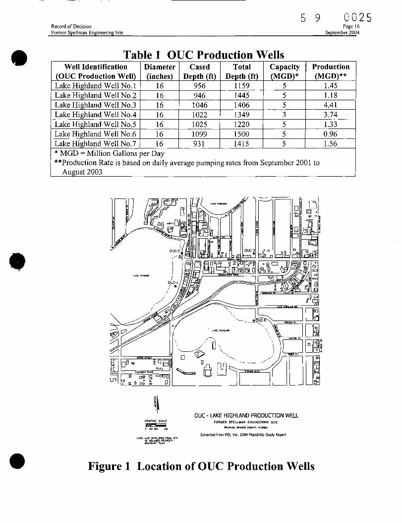
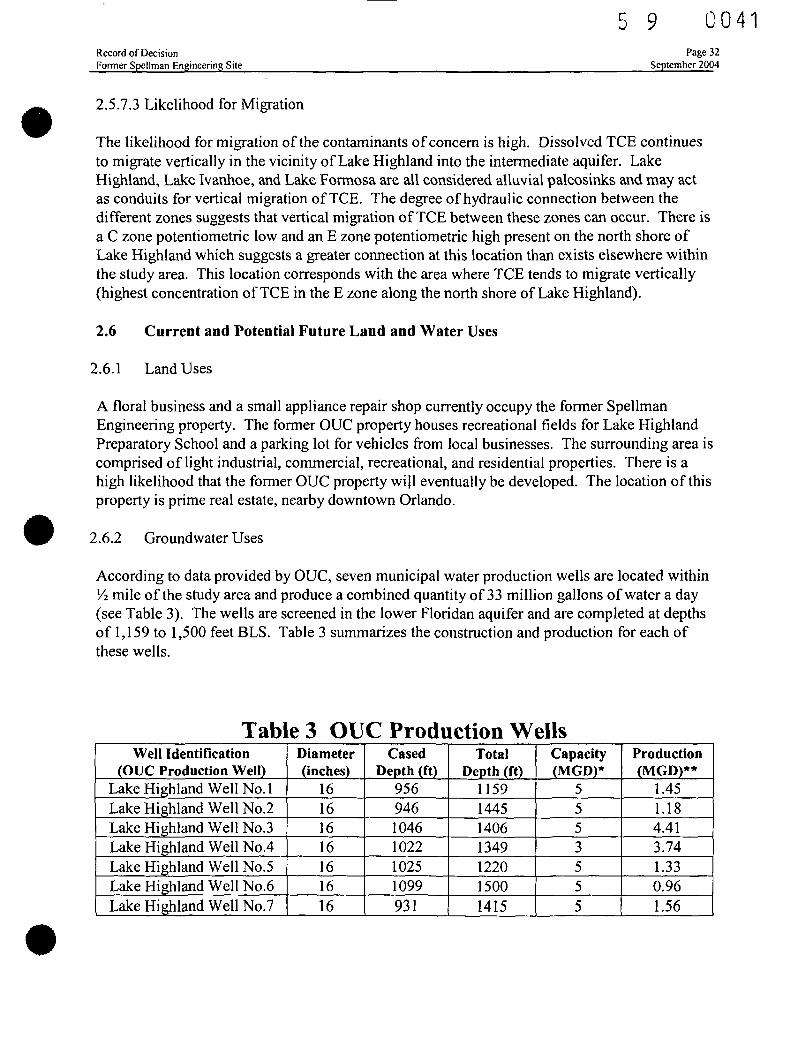
According to data provided by OUC, seven municipal water production wells are located within'/2 mile of the study area and produce a combined quantity of 33 million gallons of water a day.The size and capacity of these seven municipal wells is shown in Table 1. The location of fiveof these production wells is illustrated on Figure 1. The wells are screened within the LowerFloridan aquifer and are completed at depths of 1,159 to 1,500 feet BLS. The remaining twomunicipal wells are located south of the study area.
5 9Record of DecisionFormer Spellman Engineering Site
0 0 2 5Page 16
September 2004
Table 1 OUC Production WellsWell Identification
(OUC Production Well)Lake Highland Well No. 1Lake Highland Well No.2Lake Highland Well No.3Lake Highland Well No.4Lake Highland Well No.5Lake Highland Well No.6Lake Highland Well No.7
Diameter(inches)
16161616161616
CasedDepth (ft)
9569461046102210251099931
TotalDepth (ft)
1159144514061349122015001415
Capacity(MGD)*
5553555
Production(MGD)**
1.451.184.413.741.330.961.56
* MGD = Million Gallons per Day**Production Rate is based on daily average pumping rates from September 2001 to
August 2003
GRAPHIC SCALE
o iw 100 *eo
OUC - LAKE HIGHLAND PRODUCTION WELLFORUER SPELLUAN ENGINEERING SITE
CMLANDCX OftAHCC COWTY. flOMU
Extracted from PSI, Inc. 2004 Feasibility Study Report
Figure 1 Location of OUC Production Wells
5 9 0 0 2 6Record of Decision Page 17Former Spellman Engineering Site September 2004
The OUC's production wells are monitored monthly by the OUC Water Quality Laboratory tocheck all drinking water parameters, including chlorinated solvent compounds. Nocontamination by any volatile compounds has been detected in any of these production wells.
Since 1904, over 400 drainage wells have been installed in Orange County to control lake levelsand urban stormwater runoff. The majority of the drainage wells were installed in the UpperFloridan aquifer (Bradner, 1996), (Schiner and German, 1983). Drainage wells drain surfacewater by gravity into the aquifer and range in casing size from 4 to 26 inches in diameter withmore than half of these being 12 inches in diameter or more (Schiner and German, 1983). Thedrainage wells contribute an estimated 23 million gallons of stormwater a day to the Floridanaquifer (Bradner, 1991). At least four drainage wells are known to exist within the study area.
The drainage wells in the Orlando area, including the four known wells within a '/2 mile radiusof the former Spellman Engineering site, contribute a significant quantity of water per day,which may contain VOC contamination from runoff. Recent studies (German, 1996) indicatethat the quantities of drainage well recharge to the Upper Floridan aquifer are not insignificantwhen compared to natural recharge. According to this study, approximately 20% of the UpperFloridan water in the study area may have originated from drainage well recharge.
2.5.3 Geology
The surficial unit within the study area consists of a gray/brown to white sand to silty sand layerthat varies in thickness from 20 to 50 feet with an average thickness of 35 feet. Minor amountsof phosphorite are present within this unit. The water table is present in this unit at an averagedepth of 12 feet BGS, with the water table near the various lakes only a few feet BGS. Thelower portion of this unit has been designated as the "A" hydrogeologic zone at this Site.
Subjacent to the sand to silty sand unit is a clay unit with a thickness ranging from 1 to 12 feet.The clay unit consists of cohesive gray/green clay with minimal sand content. Below the clayunit is a gray/brown to green clayey sand/sandy clay. Sand, shell, and clay are present in thisunit as discontinuous lenses. The clayey sand/sandy clay unit thickness is approximately 30 feet.The clay and sandy clay/clayey sand units comprise the "B" hydrogeologic zone. The B Zone is
interpreted as the Peace River Formation, which is the upper, primarily siliclastic section of theHawthorne Group (Miocene) (Scott, 1988).
A thin lens of sand to gravel-sized phosphorite and quartz, clay, shell, and dolomicrite(dolostone) underlies the clay to clayey sand unit. This unit appears to be continuous atapproximately 60 to 72 feet BLS and ranges from 4 inches to 4 feet thick. This zone isdesignated the "C" hydrogeologic zone and is interpreted as the phosphatic rubble zone markingthe boundary between the Peace River Formation and the underlying Arcadia Formationdescribed by Scott.
Subjacent to the previously described phosphatic rubble zone, phosphatic stiff clay is present.The clay grades into a fine-grained dolostone (dololutite) and carbonate mud. For purposes ofcontinuity, this unit is designated hydrogeologically as the "D" Zone. Sand, shell, and clay are
5 9 0027Record of Decision Page 18Former Spellman Engineering Site September 2004
present in this unit as discontinuous lenses. These lenses did not yield a sufficient quantity ofwater to screen any monitoring wells within this zone. The dololutite unit is interpreted as theArcadia Formation, which is the lower carbonate section of the Hawthorne Group (Scott, 1988).
Phosphatic sand to shelly limestone is present at depths ranging from 86 to 108 feet BLS. Thisunit was present to a depth of 115 feet BLS in Soil Boring SB-79. Based upon information fromanother study conducted near the site, this unit is likely to be 15 to 20 feet thick and is underlainby more phosphatic dololutite and carbonate mud. The groundwater flow zone of this unit isdesignated as the "E" Zone.
Based upon the lithology at Soil Boring SB-79, the dololutite unit extends for another 60 feetuntil the top of the Ocala Limestone is encountered. The top of the Ocala Limestonecorresponds to the top of the Upper Floridan aquifer and is designated as the "F" Zone.
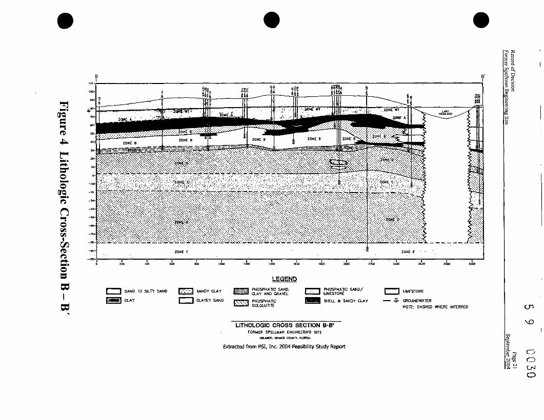
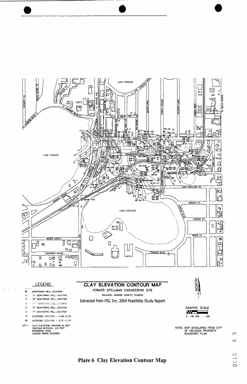
Figure 2 provides the locations of three lithologic cross-sections (A-A', B-B', and C-C'), whichare provided on Figure 3, Figure 4, and Figure 5, respectively. Measured across the subject site,the top of the clay elevations are provided on Plate 6.
Record of DecisionFormer Spellman Engineering Site
5 9 C 0 2 8Page 19
September 2004
LEGEND CROSS-SECTION TRAVERSESFORMER SPELLMAN ENGINEERING SITE
CALANDa CRANOC COUNTY. FIWDA9 MONITORING WELL LOCATION
• "A" MONITORING *£LL LOCATION
• •«• MONITORING WELL LOCATION Extracteu Mum roi, JML. iuut reosiuiuty Study Report
6 '(-.• l!C.\nO?.INC V.'LL LOCATION
• 'E' MONITORING WELL LOCATION
O "F" MONITORING ttEUL LOCATION
E GEOFRC8E. LOCUTION - 4/«S-£/98
$ GEOPROBf LOCATION - 6/01-11/01
° SURrACE WATER/SEWMENT LOCATION
IGRAPHIC SCALE
0 100 200 400
NOTE: UAP DEVELOPED FTWU CITY
OF OfiLAHDO PROPERTY
BOUNDARY PLAN
Figure 2 Cross-Section Traverses
QTQ
=
F1'N-«P+er
°2.o"no
O=
LITHOLOGIC CROSS SECTION A-A'FORMER SPELLWAN ENGINEERING SITE
ORLANDO, ORANGE COUNTY. R-ORIOA
Extracted from PSI, Inc. 2004 Feasibility Study Report
LEGEND
SAND TO SILTY SAND
CLAY
SANDY CLAY
CLAYEY SAND
PHOSPHATIC SAND.CLAY AND GRAVEL
PHOSPHATICOOLOUJTITE
PHOSPHATIC SAND
SHE1.L
GROUNDWATER
NOTE: DASHED WHEREINFERRED
% a
3 es g :rn a
3OJQ'
cOJQ
n*to
roo< ->-<•o3
wIbd
LEGEND
SAND TO SILTY SAND
CLAY
SANDY CLAY
CLAYEY SAND
PHOSPHATIC SAND.CLAY AND GRAVEL
PHOSPHATICDOLOLUT1TE
PHOSPHATIC SAND/LIMESTONE
SHELL & SANDY CLAY
LIMESTONE
GROUNOWATER
NOTE: DASHED WHERE INFERRED
s> a.g>s,2. a3 8 .
cn
LITHOLOGIC CROSS SECTION B-B'i FORMER SPELLMAN ENGINEERING SITE
ORLANDO. CHANCE COUNTY. FLORIDA.
Extracted from PSI, Inc. 2004 Feasibility Study Report
CD
3era*
oera
noi
C/3
O*
nin
<L O38.s g -m 3
SAND TO SILTY SAND
I I CLAYEY SAND
700 800
LEGEND
>A PHOSPHAT1C SAND.A CLAY AND GRAVEL
<J PHOSPHAT1CII OOLOLUTITE
SHELL & SANDY CLAY NOTE: DASHED WERE INFERRED
GROUNDWATER
LITHOLOGIC CROSS SECTION C-C'FORMER SPELLMAN ENGINEERING SITE
ORLANDO. ORAHCC COUNTY. FLORIDA
Extracted from PSI, Inc. 2004 Feasibility Study Report
CD0-J
5 9 C 0 3 2Record of Decision Page 23Former Spellman Engineering Site September 2004
2.5.4 Hydrogeology
The original assessment report performed by IT Corp in 1993 used an alpha designation for thevarious hydrogeologic zones: WT, A, B, and C. Thus, monitoring wells at the site have beenassigned "WT" (water table) "A", "B", and "C" designations that correspond to specific depths orhydrogeologic units to which the monitoring wells have been installed. These alpha designationswere retained, and expanded upon, in subsequent investigations.
"WT" monitoring wells were set to depths ranging between 15 to 20 feet BGS and are designed tointersect the top of the surficial water table. "WT" monitoring wells are screened within thesurficial silty sand to sand lithologic unit.
"A" monitoring wells were set to depths ranging between 25 and 40.5 feet BGS and are designed tointersect the boundary between the surficial silty sand to sand unit and the underlying clay to clayeysand unit. The boundary between these units was observed to be poorly consolidated during thecourse of previous studies and is evaluated to be an important TCE migration zone.
"B" monitoring wells were set to depths ranging between 43 and 54 feet BGS and are designed tomonitor groundwater quality within the clay to clayey sand unit.
"C" monitoring wells were set to depths ranging between 54.5 and 72 feet BGS and are designed tointersect a thin but horizontally persistent phosphatic clayey sand/gravel/ shell unit, which has beenevaluated to be relatively transmissive and potentially an important TCE migration zone.
"E" monitoring wells were installed to depths ranging from approximately 96 to 116 ft BLS. The EZone is a phosphatic sand and shelly limestone interbedded with D Zone sediment (phosphaticdololutite and mud).
An "F" monitoring well was set to a depth of 175 feet BLS and is in the Upper Floridan aquifer thatconsists of the Ocala Group Limestone.
The two primary aquifer systems in the study area are the non-artesian (surficial) and artesian(Floridan). The surficial aquifer is separated from the Floridan aquifer by the phosphatic clayeysands, clays, dolostone and limestone of the Hawthorne Group (Miocene) (Scott, 1988). Waterproduced from the surficial aquifer within the study area is used mainly for irrigation. The surficialaquifer extends generally to around 40 to 50 feet BLS, which is where the sandy clays of theHawthorne Group begin. The surficial aquifer is recharged primarily through rainfall, with theannual average in Orange County measured at 51.4 inches. The surficial aquifer is composed ofmarine terrace deposits of undifferentiated quartz sand (Holocene to Pleistocene) (Lichtler, 1968).
The surficial aquifer is separated from the Floridan aquifer system by the Hawthorne Group. TheHawthorne Group in Orange County consists primarily of buff-colored phosphatic dolostone andlimestone and is known as the Arcadia Formation. A thin veneer of the Peace River Formation, alsopart of the Hawthorne Group, overlies the Arcadia Formation, (Scott, 1988). The Hawthorne rangesin thicknesses of 0 to 200 feet in Orange County (Lichtler, 1968). Secondary artesian aquifers
5 9 0033Record of Decision Page 24Former Spellman Engineering Site September 2004
composed of thin shell beds, limestone, or sand is also present within the Hawthorne that producesenough water for domestic use. The permeable layers within the Hawthorne are generally of limitedextent (Scott, 1988).
The Floridan aquifer system underlies all of Orange County and is one of the most prolific aquifersin the country. Many domestic and small public supply wells draw water from the Upper Floridanzone (Lichtler, 1968). The Floridan aquifer is divided into upper and lower zones. The upper zoneof the Floridan consists primarily of the Ocala Limestone (Eocene). The Ocala Limestone underliesthe Hawthorne Group and is one of the most permeable zones within the Floridan aquifer system.The Ocala Limestone, between 0 and 125 feet thick, is composed of soft to medium hard, porousgranular limestone, which may be dolomitized to various degrees (Scott, 1992) (Lichtler, 1968).Karstic processes have greatly enhanced the secondary porosity of this formation. Karst landscape isformed by the dissolution of carbonate rock (limestone and dolostone). Sinkholes are funnel shapeddepressions that form as a result underlying carbonate rock dissolution. Dissolution of carbonateappears primarily in groundwater recharge areas where acidic surface water (pH 3-5) percolatesinto less acidic carbonate aquifers (pH > 7.0). The lower Floridan consists of several thousand feetof limestones and dolostones of the Avon Park Formation, Lake City Limestone, OldsmarFormation, and Cedar Keys Formation. The lower Floridan is the most prolific water supply sourcein Florida.
The area surrounding Orlando is a groundwater recharge area with lakes formed by sinkholedepressions, most probably including Lake Highland. Since the lake is relatively shallow, it mayhave formed over a deeply buried paleo-sinkhole. These sinkholes are termed alluvial sinkholes andare typically plugged by lateral infilling by surrounding sediment or by marine sediments. The typeof plug material can be a function of the age of the sinkhole, how quickly it formed, and theproportion of sand and clay present in the overburden. Therefore, it is not possible to determine themakeup of a particular sinkhole plug without subsurface exploration, either by drilling orconducting a geophysical survey. The plugs of alluvial sinkholes can become eroded due toactivities such as excessive well pumping, vibrations and plug puncturing through drilling orexcavation. When the plug erodes, the alluvial sinkhole is rejuvenated and becomes a raveling sink.
The degree of hydraulic connection between the surficial aquifer and the underlying confinedaquifer is indicative of the degree to which water is passing through potential permeable zonespresent in the sinkhole plug. The difference in hydraulic head between the surficial aquifer andunderlying confined aquifer at monitoring well MW-49 suggests that the plug in Lake Highland isrelatively intact. However, a potentiometric low is present in C Zone on the north shore of LakeHighland, which suggests a greater hydraulic connection between the confined aquifer in the E Zoneand the overlying surficial aquifer than exists elsewhere within the study area. This area alsocorresponds with the area where TCE tends to migrate vertically (i.e., the highest measuredconcentrations of TCE in C and E Zones are located along the north shore of Lake Highland).
The municipal wells comprising the OUC well field at Lake Highland are set into the lowerFloridan aquifer and are sampled for VOCs on a monthly basis. To date, TCE and its breakdownproducts have not been detected in any of the municipal wells near Lake Highland. Furthermore,based on the analysis of the groundwater collected from the upper Floridan aquifer monitoring well
5 9 . C C 3 4Record of Decision Page 25Former Spellman Engineering Site September 2004
installed by PSI during the Rl, TCE and its breakdown products have not been detected in the upperFloridan aquifer.
2.5.5 Direction and Rate of Groundwater Flow
The direction of groundwater flow was determined from groundwater elevation data collectedfrom monitoring wells in the study area. Utilizing the hydraulic conductivity values, soilporosity estimates, and groundwater flow direction; the rate of groundwater flow has beencalculated. The calculated hydraulic conductivity of the surficial and intermediate aquifersvaries widely from less than one-tenth of a foot per day to more than 140 feet per day.Similarly, the karst Floridan aquifer conductivity ranges widely, and may include conduit flowzones with hydraulic conductivities of hundreds of feet per day.
The water level measurements collected from the "WT" wells indicate a westerly flow directionacross the study area. These measurements indicated that the flow roughly corresponds totopography and thus, flows are toward Lake Highland to the south and toward Lake Ivanhoe tothe west. The predominant flow direction within A Zone is to the west.
The groundwater elevation measurements collected from monitoring wells installed in B Zoneindicate that the groundwater in this zone flows toward each of the three lakes in the study area;towards the north to Lake Formosa, towards the south to Lake Highland, and towards the westto Lake Ivanhoe.
The groundwater flow direction within C Zone is similar to B Zone with groundwater flowmoving west from the eastern portion of the study area towards each of the area lakes. A pointof interest for C Zone is the potentiometric low on the north shore of Lake Highland. Thispotentiometric low suggests that a hydraulic connection exists between this zone and theunderlying E Zone.
Groundwater flow within the E Zone is towards the northeast, essentially the reverse directionof the overlying hydrogeologic zones. The local groundwater flow direction centered aroundLake Highland in the E Zone may be radial, indicating recharge from C Zone or it may be to thenortheast, which also is the regional flow direction of the Floridan aquifer. Regardless ofwhether the E Zone groundwater flow direction is radial, localized radial with overallgroundwater flow to the northeast, or only northeast, the most important area where verticalcontaminant transport is occurring is along the northern shore of Lake Highland. Groundwaterquality data appears to correspond with the groundwater flow data, which indicates that thecontaminant plume is migrating primarily towards Lake Highland, then migrating verticallythrough what appears to be a paleo-sink below Lake Highland and then reversing flow direction,wrapping underneath the shallow contaminant plume and flowing to the northeast.
2.5.6 Nature and Extent of Contamination
This section presents the findings from testing of environmental media (soil, groundwater,sediment, and surface water) during the RI, and conclusions regarding the nature and extent of
5 9 0 0 3 5Record of Decision Page 26Former Spellman Engineering Site September 2004
contamination. The scope of the RI included an evaluation of historical data, sampling ofvadose zone soils in the source area, collection of groundwater samples from 72 permanentmonitoring wells and 33 temporary wells, investigation for DNAPL in the source area,collection of 18 surface water and sediment samples from Lake Highland, and the collection ofphysical and geotechnical data from the impacted media.
All groundwater, soil, sediment, and surface water samples were analyzed for VOCs (includingTCE and associated breakdown products). VOC analysis was performed by EPA Method 8260.Selected groundwater samples were also analyzed for semi-volatile organic compounds(SVOCs) including the chlorinated solvent additive 1,4-dioxane by EPA Method 8270.Additionally, selected groundwater samples also were analyzed for natural attenuationparameters.
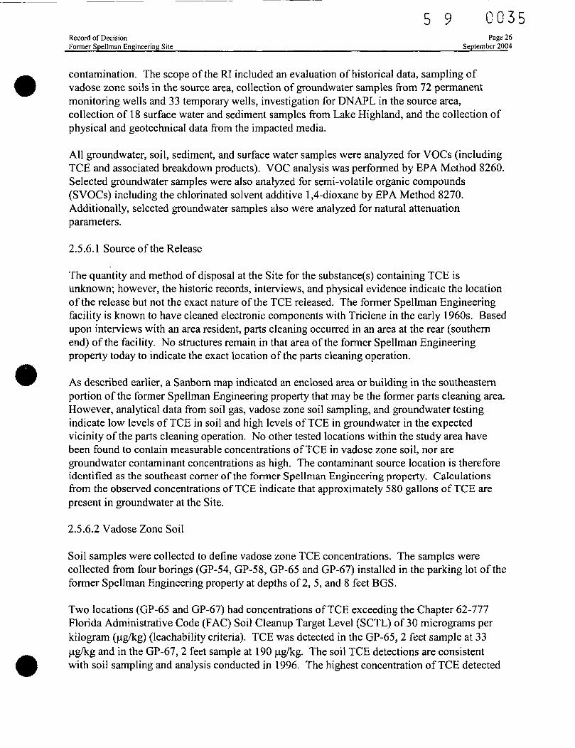
2.5.6.1 Source of the Release
The quantity and method of disposal at the Site for the substance(s) containing TCE isunknown; however, the historic records, interviews, and physical evidence indicate the locationof the release but not the exact nature of the TCE released. The former Spellman Engineeringfacility is known to have cleaned electronic components with Triclene in the early 1960s. Basedupon interviews with an area resident, parts cleaning occurred in an area at the rear (southernend) of the facility. No structures remain in that area of the former Spellman Engineeringproperty today to indicate the exact location of the parts cleaning operation.
As described earlier, a Sanbom map indicated an enclosed area or building in the southeasternportion of the former Spellman Engineering property that may be the former parts cleaning area.However, analytical data from soil gas, vadose zone soil sampling, and groundwater testingindicate low levels of TCE in soil and high levels of TCE in groundwater in the expectedvicinity of the parts cleaning operation. No other tested locations within the study area havebeen found to contain measurable concentrations of TCE in vadose zone soil, nor aregroundwater contaminant concentrations as high. The contaminant source location is thereforeidentified as the southeast corner of the former Spellman Engineering property. Calculationsfrom the observed concentrations of TCE indicate that approximately 580 gallons of TCE arepresent in groundwater at the Site.
2.5.6.2 Vadose Zone Soil
Soil samples were collected to define vadose zone TCE concentrations. The samples werecollected from four borings (GP-54, GP-58, GP-65 and GP-67) installed in the parking lot of theformer Spellman Engineering property at depths of 2, 5, and 8 feet BGS.
Two locations (GP-65 and GP-67) had concentrations of TCE exceeding the Chapter 62-777Florida Administrative Code (FAC) Soil Cleanup Target Level (SCTL) of 30 micrograms perkilogram (u-g/kg) (teachability criteria). TCE was detected in the GP-65,2 feet sample at 33ug/kg and in the GP-67, 2 feet sample at 190 fig/kg. The soil TCE detections are consistentwith soil sampling and analysis conducted in 1996. The highest concentration of TCE detected
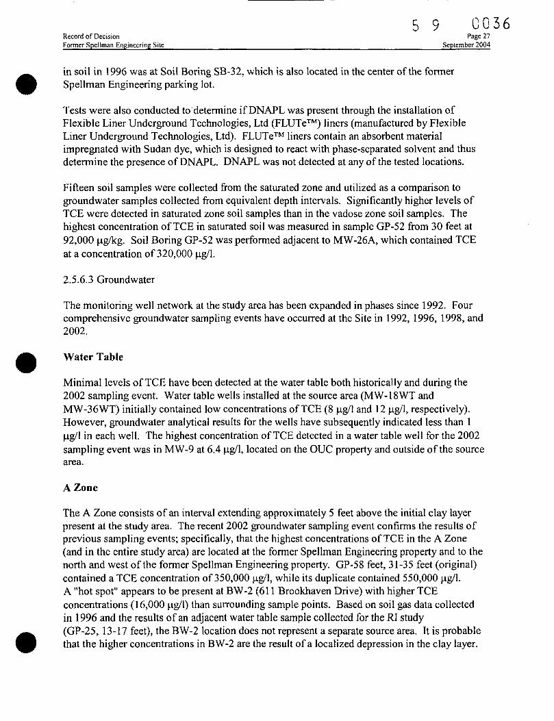
5 9 C O 3 6Record of Decision Page 27Former Spellman Engineering Site September 2004
in soil in 1996 was at Soil Boring SB-32, which is also located in the center of the formerSpellman Engineering parking lot.
Tests were also conducted to determine if DNAPL was present through the installation ofFlexible Liner Underground Technologies, Ltd (FLUTe™) liners (manufactured by FlexibleLiner Underground Technologies, Ltd). FLUTe™ liners contain an absorbent materialimpregnated with Sudan dye, which is designed to react with phase-separated solvent and thusdetermine the presence of DNAPL. DNAPL was not detected at any of the tested locations.
Fifteen soil samples were collected from the saturated zone and utilized as a comparison togroundwater samples collected from equivalent depth intervals. Significantly higher levels ofTCE were detected in saturated zone soil samples than in the vadose zone soil samples. Thehighest concentration of TCE in saturated soil was measured in sample GP-52 from 30 feet at92,000 fig/kg. Soil Boring GP-52 was performed adjacent to MW-26A, which contained TCEat a concentration of 320,000 fig/1.
2.5.6.3 Groundwater
The monitoring well network at the study area has been expanded in phases since 1992. Fourcomprehensive groundwater sampling events have occurred at the Site in 1992, 1996, 1998, and2002.
Water Table
Minimal levels of TCE have been detected at the water table both historically and during the2002 sampling event. Water table wells installed at the source area (MW-18WT andMW-36WT) initially contained low concentrations of TCE (8 jig/1 and 12 jag/1, respectively).However, groundwater analytical results for the wells have subsequently indicated less than 1jag/l in each well. The highest concentration of TCE detected in a water table well for the 2002sampling event was in MW-9 at 6.4 ^g/1, located on the OUC property and outside of the sourcearea.
A Zone
The A Zone consists of an interval extending approximately 5 feet above the initial clay layerpresent at the study area. The recent 2002 groundwater sampling event confirms the results ofprevious sampling events; specifically, that the highest concentrations of TCE in the A Zone(and in the entire study area) are located at the former Spellman Engineering property and to thenorth and west of the former Spellman Engineering property. GP-58 feet, 31-35 feet (original)contained a TCE concentration of 350,000 u.g/1, while its duplicate contained 550,000 jjg/1.A "hot spot" appears to be present at BW-2 (611 Brookhaven Drive) with higher TCEconcentrations (16,000 ng/1) than surrounding sample points. Based on soil gas data collectedin 1996 and the results of an adjacent water table sample collected for the RI study(GP-25, 13-17 feet), the BW-2 location does not represent a separate source area. It is probablethat the higher concentrations in BW-2 are the result of a localized depression in the clay layer.
5 9 0 0 3 7Record of Decision Page 28Former Spellman Engineering Site September 2004
The predominant migration pattern of TCE in A Zone groundwater is toward Lake Highland andcorrelates to the direction of groundwater flow (southwest). Lower concentrations of TCE aremigrating in a more dispersed pattern toward the other area lakes, Lake Ivanhoe to the west andLake Formosa to the north. While migrating horizontally in the direction of the various arealakes, the A Zone TCE plume is also migrating vertically into the B Zone beneath the claybeginning in an area just downgradient of the source area.
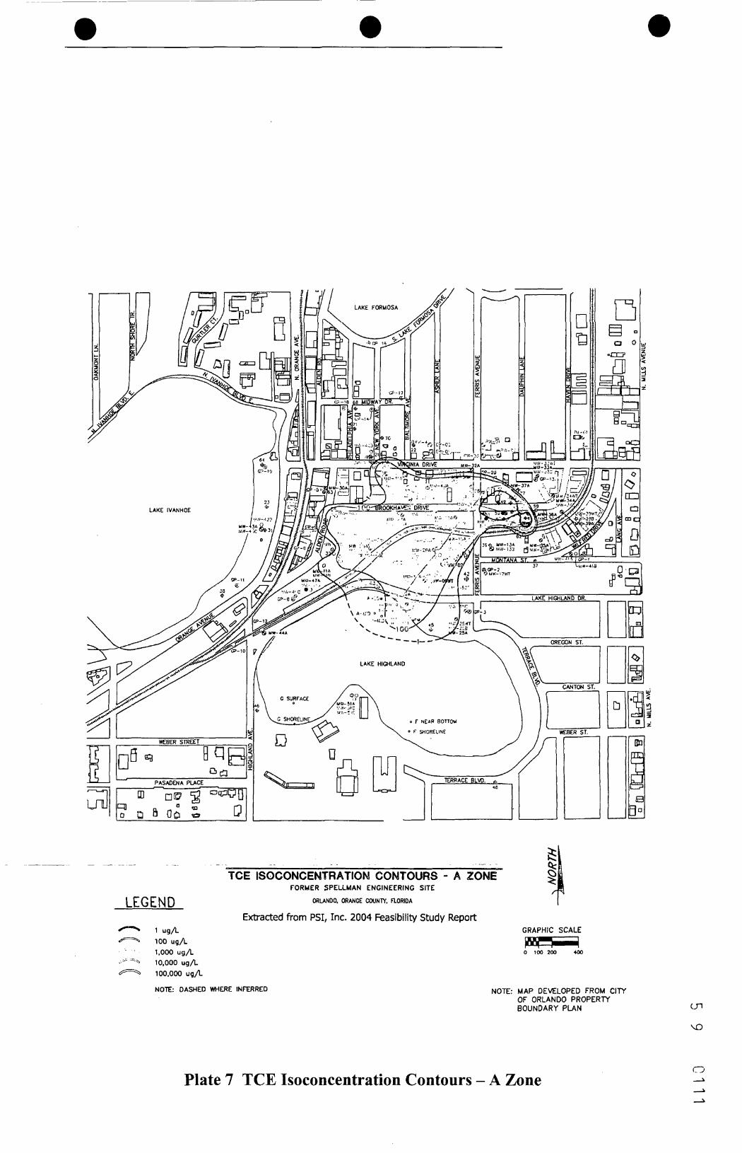
The analytical results indicate that the plume consists almost exclusively of TCE, with very lowconcentrations of daughter or breakdown products. Exceptions to the plume chemistry in the AZone include GP-33A (8.7 ug/1 of VC, 46 ug/1 of cis- or, trans-l,2-DCE) and MW-29A(140 (ag/1 of cis-l,2-DCE). Isoconcentration contours of the TCE contamination in the A zoneare shown on Plate 7.
BZone
The B Zone is lithologically heterogeneous and includes the uppermost clay layer. Thethickness of the B Zone is generally between 20 to 30 feet. Many of the Geoprobe™screenpoints targeted a sandy clay/clayey sand layer with shell that was present at many testedlocations throughout the study area. This layer was locally water-bearing.
The RI analytical results for the B Zone groundwater samples indicate that there is a moreextensive B Zone TCE plume in the northern portion of the study area than was previouslyevaluated. Additionally, an area of high concentrations of TCE (greater than 10,000 ug/1) wasmeasured in the B Zone that corresponds to the high concentration area in the A Zone. This areaappears to begin north of the MW-29 and extends to Lake Highland. A lobe of the highconcentration zone also extends to the north, just beyond Brookhaven Drive.
Daughter or breakdown products are relatively more prevalent in the B Zone, with the detectionsof cis-l,2-DCE, trans-1,2-DCE, and VC. TCE remains the predominant analyte detected;however, these daughter products are increasing in concentrations within this zone.
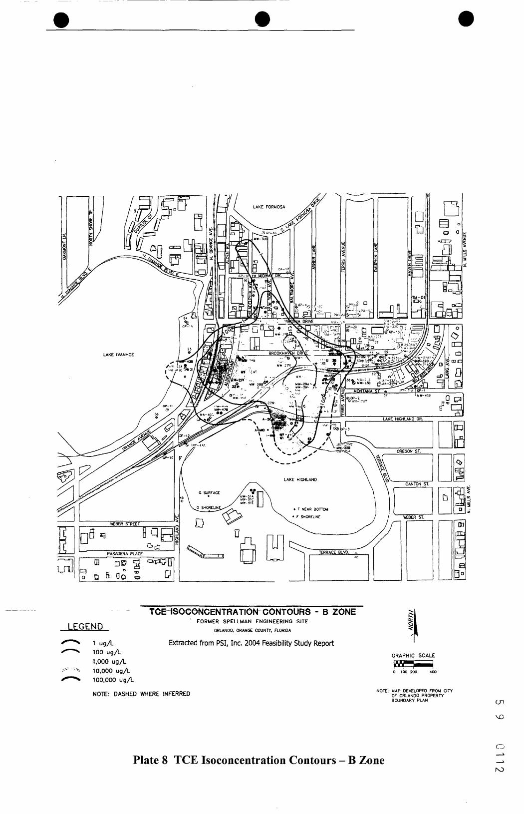
TCE contamination in the B Zone has the greatest horizontal extent relative to othercontaminated intervals at the Site. High levels of TCE are present up to and, presumably,underneath Lake Highland. Based upon the groundwater test results from MW-43B, low levelsof TCE (20 ug/1) may extend under Lake Ivanhoe within the B Zone. Isoconcentration contoursof the TCE contamination in the B zone are shown on Plate 8.
CZone
The C Zone lithologic unit is a relatively thin layer of phosphatic sand and gravel that underliesthe B Zone and caps underlying fine grained phosphatic carbonate mud and dolomite(dololutite). This zone is laterally persistent and has been evaluated as a potential zone forcontaminant transport.
5 9 C 0 3 8Record of Decision Page 29Former Spellman Engineering Site September 2004
The laboratory results indicate that C Zone TCE contamination is not as laterally extensive or asconcentrated as TCE contamination in the overlying A and B Zones. TCE remains thepredominant analyte detected; however, daughter products are increasing in concentrationswithin this zone.
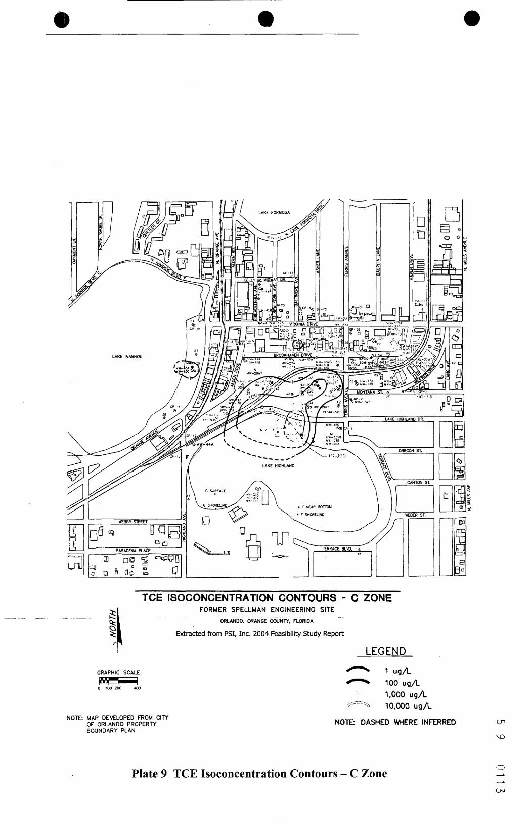
The most significant area of C Zone contamination is the north shore of Lake Highland withTCE concentrations of 3,600 u£/l, 9,500 ng/1, and 27,000 ug/1 detected at GP-43, MW-49Cand GP-44, respectively. TCE contamination in the C Zone along the north shore of LakeHighland appear to disperse laterally with high concentrations detected in GP-43 locatedapproximately 260 feet to the west of MW-49C. Isoconcentration contours of TCEcontamination in the C zone are shown on Plate 9.
DZone
The D Zone is a relatively impermeable zone consisting of fine grained dolomite and dolomiticmuds (dololutite) that appears, with the probable exception of an area near the northern shore ofLake Highland, to act as a semiconfming unit between the C and E Zones. The D Zone wasevaluated as a stratum too impermeable in which to install monitoring wells. Therefore, nogroundwater samples were collected from the D Zone during the RJ.
EZone
The E Zone is a phosphatic sand and shelly limestone interbedded with D Zone sediment(phosphatic dololutite and mud). This unit is 7 to 29 feet thick and begins at depths ofapproximately 90 feet BGS. Five monitoring wells were installed in E Zone for the RI andsampled for VOC analysis, one was also sampled for SVOC analysis.
The analytical results from E Zone groundwater samples indicate the highest concentrations ofTCE present in the samples collected from monitoring well MW-49E, located on the north shoreof Lake Highland, at 740 u.g/1 during the April 2002 sampling event and 2,200 fag/1 during theOctober n2001 sampling event. Concentrations of TCE breakdown products appear to beincreasing relative to TCE concentrations in E Zone over time. For instance, cis-l,2-DCE wasmeasured at 840 ja.g/1 in the MW-49E groundwater sample for February 2003, 300 [ig/1 duringApril 2002, and 160 jag/1 during October 2001. Isoconcentration contours of TCEcontamination in the E zone are shown on Plate 10.
FZone
The F Zone refers to the upper Floridan aquifer that consists of the Ocala Group Limestone.This unit is present from 175 feet BGS at the MW-52 location and was present to the maximumdrilled depth of 186 feet BGS.
The analytical results from the groundwater sampling collected from MW-52F revealed no TCEor other chlorinated solvent compounds. Based on the groundwater sample collected from
Record of DecisionFormer Spellman Engineering Site
5 9 0:0-39Page 30
September 2004
MW-52F, TCE originating from the former Spellman Engineering property does not appear tohave migrated into the upper Floridan aquifer.
Lower Floridan Aquifer
The lower Floridan aquifer consists of all or portions of several formations and averages about1500 feet in thickness within Orange County. The lower Floridan is separated from the upperFloridan aquifer by a semi-confining unit of less permeable micritic limestone and densedolomitic limestone. This semi-confining unit is about 500 feet thick. The lower Floridanaquifer consists of limestone and fractured dolomite.
The lower Floridan aquifer is prolific, with municipal supply wells yielding 3,000 to 5,000gallons per minute with 10 to 25 feet of drawdown. While the Avon Park Formation confininglayer is thick and relatively impermeable, hydrogeologic studies have demonstrated a hydraulicconnection between the upper and lower Floridan aquifers.
No groundwater sampling was conducted for the Lower Floridan aquifer during the RI;however, the OUC production wells are periodically tested during routine monitoring and revealno detections of chlorinated solvents.
An estimate of TCE mass in the subsurface has been calculated using the comparison ofestimated TCE in groundwater mass and TCE in soil mass per cubic foot to derive total TCEmass in the saturated zone per cubic foot (see Table 2). These estimates have been translatedinto gallons for reference. An estimate of the mass of TCE currently in groundwater at the Siteis approximately 580 gallons, distributed among the zones as shown in Table 2.
Table 2 Estimated Volume of TCEZone
ABCE
Total
Weight in grams2.13E+061.07E+064.65E+042.18E+043.27E+06
Volume in gallons378.95189.758.253.85580.8
2.5.6.4 Surface Water
Surface water samples were collected to evaluate whether contaminated groundwater from theformer Spellman Engineering site is discharging into Lake Highland. Other lakes in the areasuch as Lake Ivanhoe to the west and Lake Formosa to the north may also be receptors ofgroundwater originating from the former Spellman Engineering site. However, existing dataindicates that the TCE groundwater plume near Lake Ivanhoe is too deep to likely affect LakeIvanhoe's surface water or sediment.
5 9 0 0 4 0Record of Decision Page 31Former Spellman Engineering Site September 2004
Two of the surface water samples from Lake Highland contained trace detections of TCE.TCE was detected in surface water sample A, Shoreline, surface depth, at 0.39 u.g/1, and insurface water sample A, 50 feet offshore at mid-depth at 0.66 jag/1. Although theseconcentrations are significantly below any established surface water standard, this is the locationwhere corresponding sediment samples in the Rl indicated VOCs were present.
2.5.6.5 Sediments
Sediment samples were collected at various depths within Lake Highland to evaluate whethercontaminated groundwater from the former Spellman Engineering property has impacted lakesediment. Two sediment samples contained detectable concentrations of TCE. TCE wasdetected in sediment sample A, 50 feet offshore, at 1-foot depth, at 36 fig/kg (with 17 ug/kg oftetrachloroethene [PCE]), and in sediment sample A, shoreline, at 2-foot depth at 6.6 fJ.g/kg.
2.5.7 Location of Contamination and Migration
2.5.7.1 Lateral and Vertical Extent of Contamination
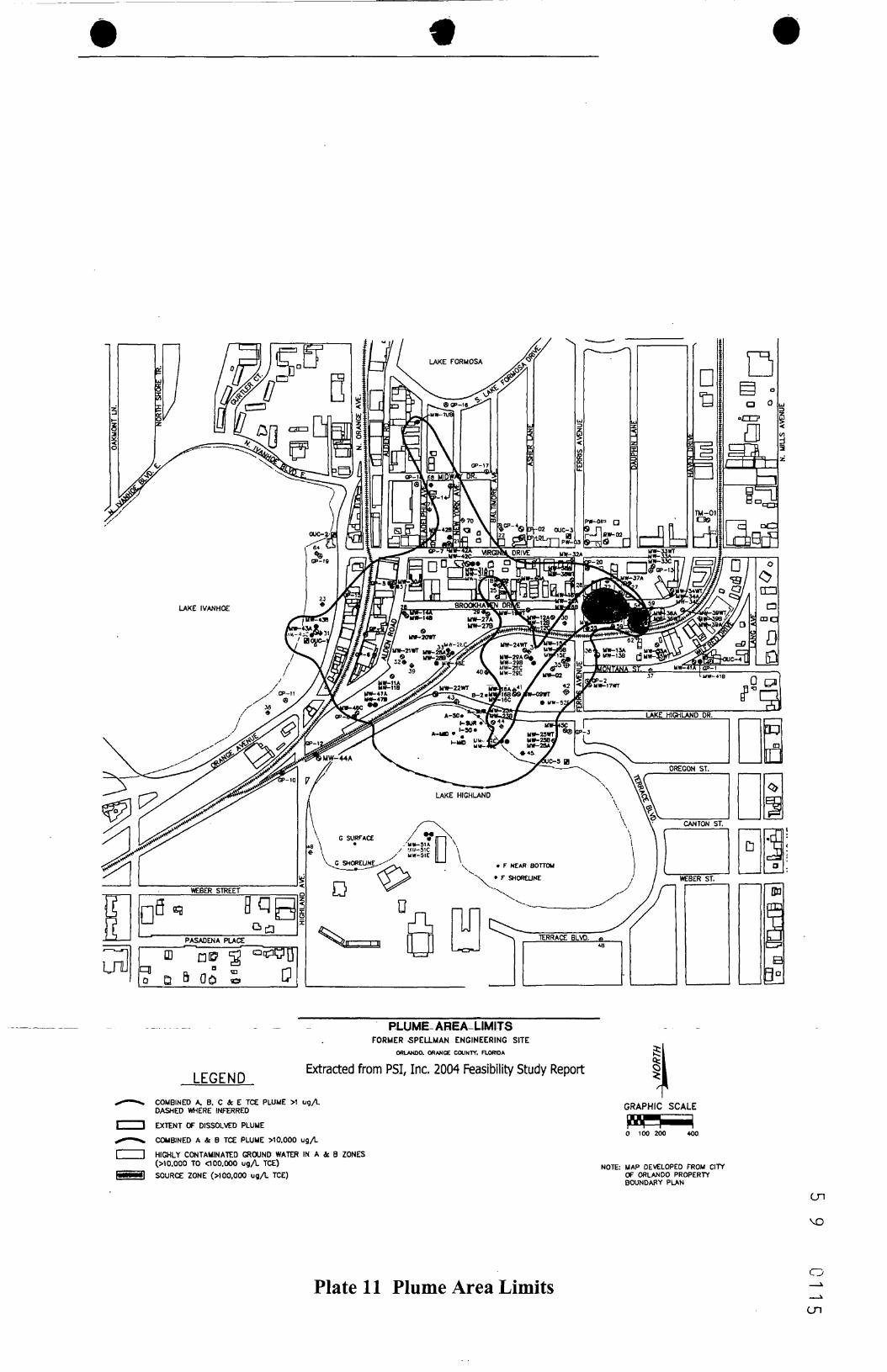
Groundwater contamination at the site extends both laterally and vertically from the formerSpellman Engineering property with the highest contamination levels found at the FormerSpellman Engineering property. The groundwater plume encompasses approximately 40 acresand vertically extends to a depth of over 100 feet BLS.
Plate 11 presents the lateral extent of groundwater contamination. The TCE plume does extendlaterally to Lake Highland in which trace levels of TCE have been detected in the surface waterand sediment.
2.5.7.2 Current and Potential Future Surface and Subsurface Routes of Human or EnvironmentalExposure
The only current populations at risk of exposure to surface soil, subsurface soil, or shallowgroundwater is the irrigation or maintenance worker. If excavation were to occur in areas wherecontamination is near the surface, worker exposure could occur. However, there is no exposedsurface soil or subsurface soil on the former Spellman Engineering property (all areas are paved orcovered with buildings), and the soils at the former OUC maintenance facility have beenremediated, regraded and redeveloped as recreational or parking areas, in large part. No evidencehas been found of intrusive subsurface activities in the area of concern. There is supplied potablewater available to all properties in the area, and no residents using shallow well water forconsumptive purposes have been identified near the Site. However, a well survey indicates thatlandscaping irrigation wells are in use within the study area. Under future scenarios, there is apotential for exposure to surface and subsurface soils and shallow groundwater throughconstruction, maintenance, or irrigation activities, as well as the possibility of residential use of theproperty. It is not expected that the current land use in the areas of concern (commercial, lightindustrial, and recreational) will change in the near future.
5 9 0 0 4 1Record of DecisionFormer Spellman Engineering Site
Page 32September 2004
2.5.7.3 Likelihood for Migration
The likelihood for migration of the contaminants of concern is high. Dissolved TCE continuesto migrate vertically in the vicinity of Lake Highland into the intermediate aquifer. LakeHighland, Lake Ivanhoe, and Lake Formosa are all considered alluvial paleosinks and may actas conduits for vertical migration of TCE. The degree of hydraulic connection between thedifferent zones suggests that vertical migration of TCE between these zones can occur. There isa C zone potentiometric low and an E zone potentiometric high present on the north shore ofLake Highland which suggests a greater connection at this location than exists elsewhere withinthe study area. This location corresponds with the area where TCE tends to migrate vertically(highest concentration of TCE in the E zone along the north shore of Lake Highland).
2.6 Current and Potential Future Land and Water Uses
2.6.1 Land Uses
A floral business and a small appliance repair shop currently occupy the former SpellmanEngineering property. The former OUC property houses recreational fields for Lake HighlandPreparatory School and a parking lot for vehicles from local businesses. The surrounding area iscomprised of light industrial, commercial, recreational, and residential properties. There is ahigh likelihood that the former OUC property wi|l eventually be developed. The location of thisproperty is prime real estate, nearby downtown Orlando.
2.6.2 Groundwater Uses
According to data provided by OUC, seven municipal water production wells are located within!/2 mile of the study area and produce a combined quantity of 33 million gallons of water a day(see Table 3). The wells are screened in the lower Floridan aquifer and are completed at depthsof 1,159 to 1,500 feet BLS. Table 3 summarizes the construction and production for each ofthese wells.
Table 3 OUC Production WellsWell Identification
(OUC Production Well)Lake Highland Well No. 1Lake Highland Well No.2Lake Highland Well No.3Lake Highland Well No.4Lake Highland Well No.5Lake Highland Well No.6Lake Highland Well No.7
Diameter(inches)
16161616161616
CasedDepth (ft)
9569461046102210251099931
TotalDepth (ft)
1159144514061349122015001415
Capacity(MGD)*
5553555
Production(MGD)**
1.451.184.413.741.330.961.56
5 9 0 0 4 2Record of DecisionFormer Spellman Engineering Site
Page 33September 2004
Well Identification(OUC Production Well)
Diameter(inches)
CasedDepth (ft)
TotalDepth (ft)
Capacity(MGD)*
Production(MGD)**
* MOD = Million Gallons per Day**Production Rate is based on daily average pumping rates from September 2001 to August2003
These and other water production wells provide supplied potable water to all properties in thestudy area. In addition to these seven OUC production wells, the wells presented in Table 4were described by the Water Management District records or were identified through visualobservation during a walking survey in the vicinity of the Site.
Table 4 Potable Well SurveyInformation
Source
Resident
Visually Located
SJRWMD
USGS
Location
1633 Ferris Ave
700 Lake Formosa Dr10 10 Montana
7 14 Lake Highlander
14 16 Ferris Ave1617 Dauphne
1019 Baltimore St13 16 Portland Ave1 60 East Ivanhoe
3 128 Bay Lake RdLat 283328: Long 812201Lat 283327: Long 8 12229Lat 283327: Long 8 12226Lat 283330: Long 8 12234Lat 283330: Long 8 12226Lat 283338: Long 8 12227Lat 283340: LongJ 12225Lat 283340: Long 8 12228
Comments
Use verified by resident, irrigation & washingpurposes only
Observation wells, not verifiedPossible well apparatus, not verified
Possible well apparatus, not verified
Possible well apparatus, not verifiedPossible well shed, not verified
Private, not verifiedIrrigation, not verifiedIrrigation, not verified
Private, not verified, unable to locate on mapNot verifiedNot verifiedNot verifiedNot verifiedNot verifiedNot verifiedNot verifiedNot verified
Note: The City of Orlando has performed semi-annual testing of private wells in the area andno contamination has ever been identified.
It is anticipated that the future supply of drinking water will be from OUC Utilities and any newprivate wells will only be permitted for irrigation purposes.
2.7 Summary of Site Risks
2.7.1 Summary of Human Health Risk Assessment
The Baseline Risk Assessment estimates what risks the site poses if no action were taken. Itprovides the basis for taking action and identifies contaminants and exposure pathways that
5 9 C 0 4 3Record of DecisionFormer Spellman Engineering Site
Page 34September 2004
need to be addressed by the remedial action. This section of the ROD summarizes the results ofthe baseline risk assessment for this Site.
2.7.1.1 Identification of Chemicals of Potential Concern
The Baseline Risk Assessment evaluated chemicals of potential concern (COPC) in each of themedia investigated {surface soil; subsurface soil; sediment; A, B, or C zone groundwater(direct exposure groundwater); E zone groundwater (residential exposure groundwater); surfacewater; and, sediment}. The maximum detected concentration of each analyte in each mediumwas compared to risk-based screening values to identify COPCs.
As summarized in Table 5, a total of 19 COPCs were identified at the Site. One COPC wasidentified in both surface soil and subsurface soil. There were no COPCs identified forsediment or surface water. Eighteen COPCs were identified for direct exposure groundwater(i.e., A, B, and C zones), and seven COPCs were identified for residential exposure groundwater(i.e., E zone).
Table 5 Chemicals of Potential ConcernChemicals of Potential
Record of DecisionFormer Spellman Engineering Site
5 9 C Q 4 4Page 35
September 2004
2.7.1.2 Exposure Assessment
Exposure pathways that formed the basis for the risk assessment were identified based on bothcurrent and hypothetical future land use at the Site. Contaminated media evaluated for exposureincluded surface soil, subsurface soil, and groundwater. Since no sediment or surface waterCOPCs were identified, these media were not evaluated further. The potential receptorpopulations included construction workers, irrigation/maintenance workers, adult residents,child residents, and aggregate (adult/child) residents. The routes of exposure evaluated wereoral ingestion, dermal contact, and inhalation.
The Conceptual Site Model developed in the Baseline Risk Assessment (BRA) is presented inTable 6.
Table 6 Conceptual Site Model (Human Receptors)
Scenario
CurrentUse
Future Use
Future Use
Future Use
Receptor
Irrigation/Maintenance Worker
Child and AdultResident
Irrigation/Maintenance Worker
ConstructionWorker
ExposurePathway(s)
DirectGroundwater
ResidentialGroundwater
DirectGroundwater
Surface Soil
DirectGroundwater
Subsurface Soil
Exposure Routes
Incidental Ingestion
Dermal Contact
Inhalation of Volatiles
Incidental Ingestion
Dermal Contact while showering
Inhalation of Volatiles while showering
Inhalation of Volatiles
Ingestion
Dermal ContactIncidental Ingestion
Dermal Contact
Incidental Ingestion
Dermal Contact
Incidental Ingestion
Dermal Contact
Based on the conceptual site model, the following scenarios were quantified and evaluated inthe risk assessment:
• Future Construction Worker Exposure to Surface Soil• Future Construction Worker Exposure to Subsurface Soil• Current Irrigation/Maintenance Worker Direct Exposure to Groundwater• Future Construction Worker Direct Exposure to Groundwater
5 9 0 0 4 5Record of Decision Page 36Former Spellman Engineering Site September 2004
• Future Irrigation/Maintenance Worker Direct Exposure to Groundwater• Future Resident (adult, child and aggregate 30-year) Exposure to Groundwater
2.7.1.3 Toxicity Assessment
The Baseline Risk Assessment utilized information from the Integrated Risk InformationSystem (IRIS), Health Effects Assessment Summary Tables (HEAST), National Center forEnvironmental Assessment (NCEA), and Agency for Toxic Substances and Disease Registry(ASTDR) to assess the toxicity of the COPCs. The assessment evaluated both carcinogenic andnon-carcinogenic effects of these chemicals.
TCE, the chemical released from the former Spellman Engineering property and the principalcontaminant identified during the RI, is generally persistent in the environment. TCE is subjectto biotransformation in the environment under favorable subsurface conditions, and is notconsidered to be bioaccumulative through environmental uptake.
2.7.1.4 Risk Characterization
For carcinogens, risks are generally expressed as the incremental probability of an individual'sdeveloping cancer over a lifetime as a result of exposure to the carcinogen. Excess lifetimecancer risk is calculated from the following equation:
Risk = GDI x SFwhere:
Risk = a unitless probability of an individual's developing cancerGDI = chronic daily intake averaged over 70 years (mg/kg-day)
SF = slope factor, expressed as (mg/kg-day)"1
An excess lifetime cancer risk of 1 .OE-06 indicates that an individual experiencing thereasonable maximum exposure estimate has a one in a million chance of developing cancer as aresult of site-related exposure. This is referred to as an "excess lifetime cancer risk" because itwould be in addition to the risks of cancer individuals face from other causes such as smokingor exposure to too much sun. EPA's generally acceptable risk range for site-related exposures isof 1.0E-04to 1.OE-06.
The potential for non-carcinogenic effects is evaluated by comparing an exposure level over aspecified period (e.g., life-time) with a reference dose (RfD) derived for a similar exposureperiod. A RfD represents a level that an individual may be exposed to that is not expected tocause any deleterious effect. The ratio of exposure to toxicity is call a hazard quotient (HQ).A HQ less than 1 indicates that a receptor's dose of a single contaminant is less than the RfD,and that toxic non-carcinogenic effects from that chemical are unlikely. The hazard index (HI)is generated by adding the HQs for all chemicals that affect the same target organ (e.g., liver) orthat act through the same mechanism of action within a medium or across all media to which agiven individual may reasonably be exposed. An HI less than 1 indicates that, based on the sumof all HQs from different contaminants and exposure routes, toxic non-carcinogenic effects from
5 9 0 0 4 6Record of DecisionFormer Spellman Engineering Site
Page 37September 2004
all contaminants are unlikely. A HI greater than 1 indicates that site-related exposures mightpresent a risk to human health. The HQ is calculated as follows:
Non-cancer HQ = CDI/RfDWhere:
GDI = Chronic daily intakeRfD = reference dose
GDI and RfD are expressed in the same units and represent the same exposure period(i.e., chronic, subchronic, or short-term).
The quantitative aggregate risks calculated for each exposure scenario under a reasonablemaximum exposure are summarized in Table 7. EPA considers risks below l.OE-06(one in a million) to be de minimus, and risks between 1.0 E-04 (one in ten thousand) and1.0 E-06 to be acceptable.
Table 7 Summary of Elevated Aggregate Risks IdentifiedExposure Scenario
Irrigation/Maintenance WorkerConstruction Worker
Resident (adult)Resident (child)
Current RiskCarcinogenic
4.1 E-04N/AN/AN/A
HI5.4 E+00
N/AN/AN/A
Future RiskCarcinogenic
4.1 E-042.7 E-053.3 E-033.3 E-03
HI5. 4 E+004.1 E+015.0 E+011.9 E+00
Evaluation of the COPCs for exposure, toxicity, and risk results in identification ofcontaminants of concern (COC) for the Site. The COCs are those chemicals found in theenvironment that have or may have an unacceptable harmful effect on human health or theenvironment. The COCs are media-specific, and are based on either a current or futureexposure pathway that produces an unacceptable risk (carcinogenic or non-carcinogenic) to anactual or hypothetical receptor due to the toxicity of the chemical. At the former SpellmanEngineering site, five chemicals were identified in groundwater as COCs under either one orboth of two general exposure scenarios, as summarized below:
• Direct Exposure to Groundwater (construction and irrigation worker scenarios)TCE1,2-dibromo-3-chloropropane
• Residential Exposure to Groundwater (child, adult, and aggregate scenarios)TCEcis-1,2-dichloroethenevinyl chloridetetrahydrofuran
5 9 0 0 4 7Record of Decision Page 38Former Spellman Engineering Site September 2004
2.7.1.5 Uncertainties
There are uncertainties that are inherent in the risk assessment process. The factors that maylead to either an overestimation or an underestimation of the potential adverse human healtheffects and associated environmental risks posed by exposures to analytes at the formerSpellman Engineering site include the following:
- The analytical data presented may not reflect actual site concentrations for all analytes at thepresent time. Data have been collected during several years of investigation at the formerSpellman Engineering site. However, concentrations are not expected to be higher than thevalues presented here because activities have ceased, and no new sources have been added. It isexpected that the concentrations presented in the BRA may actually overestimate the trueexposure conditions now and in the future due to processes such as biodegradation and dilutionthat have occurred since the most recent sampling.
- For certain of the COPCs (primarily TCE in direct exposure groundwater), statistical analysiswas not possible due to the elevated standard deviations for the data. In these instances, themaximum value was used for the assessment of risks. It is unlikely that this will result inunderestimation of the true risk from exposure to this COC under the conditions that wereassumed.
- Assumptions regarding, for example, body weight, average human lifetime, and other factorswere based on reasonable estimates from available sources and may not be accurate for specificindividuals whose characteristics vary from the conservative general conditions which wereassumed in the BRA. However, standard assumptions were employed in those cases whereinformation was available and professional judgment was applied elsewhere.
- Factors that affect the disposition of absorbed Site contaminants, such as metabolism,distribution, bioconcentration and excretion, were not explicitly considered in detail in theintake and risk calculations. Rather, reasonable and conservative assumptions were employedwhich are unlikely to underestimate the true exposure conditions. Corrections regardingroute-of-exposure were made to reflect such conditions.
- The mechanism of action for toxicity of the site contaminants is not taken into account and isnot known with certainty in many cases, particularly regarding their putative carcinogeniceffects. The rather specific nature of the carcinogenic effects in animal studies suggest that anyextrapolation to humans will be heavily dependent on the assumption of equivalent response inman, an assumption which often is not supported by the epidemiological data.
- Consistent with standard risk assessment practice, the U.S. EPA Reference Doses (RfDs) andCarcinogenic Slope Factors (CSFs) were used to reflect toxicity endpoints of interest.
- The intake and risk calculations assume that the exposure conditions can be represented by adeterministic approach that views each variable separately and may result in inappropriatetargets because conservative assumptions are layered on top of another.
5 9 0 0 4 8Record of Decision Page 39Former Spellman Engineering Site September 2004
2.7.2 Summary of Ecological Risk Assessment
During the RI, a review of State and Federal ecological databases was performed, a site surveywas conducted, and the ecological exposure pathway was evaluated. The database review foundthat no known critical habitats were in the immediate vicinity of the Site, no wetland areas weremapped at the Site, and that none of the threatened or endangered species found in OrangeCounty urban environments had been observed in the immediate vicinity of Lake Highland. Asite ecological survey performed during the RI supported the findings of the database review.
Evaluation of ecological exposure pathways was performed in conjunction with preparation ofthe RI and BRA. The only media identified during the RI with COC were soil and groundwater.Since all of the contaminated site soils are isolated from the environment by pavement, noviable ecological exposure pathway was considered to be present. Similarly, groundwater is notan exposure media of ecological concern except at the point of discharge to a surface waterbody. Since sampling of sediment and surface water in Lake Highland did not indicate thepresence of contaminants at levels of concern, this pathway also is considered incomplete. Thisevaluation is consistent with the expected outcome developed during RI work planning.
2.8 Remedial Action Objectives
Remedial Action Objectives (RAOs) for the former Spellman Engineering site were developedfrom a review of the results of the site sampling data, fate and transport evaluations, riskassessment results, and review of the Applicable or Relevant and Appropriate Requirement(ARARs) (State and Federal drinking water standards). The clean-up goals were derivedprincipally from ARARs, and correlate closely with the human health risk assessment results.At the Site, the potential cancer and non-cancer risks to trespassers, potential future industrialworkers, and potential future residents exceeded both the carcinogenic risk threshold of 1.0 E-04and the HQ of 1, as well as the applicable drinking water standards..
Under the National Contingency Plan, EPA's goal is to meet ARARs and reduce the excesscancer risk to within or below the range of 1.0 E-04 to 1.0 E-06 and a hazard index below 1. Toachieve this goal, EPA is establishing the following Remedial Action Objectives for cleanup ofthe former Spellman Engineering site:
• Prevent potential degradation of the Floridan aquifer caused by the release of contaminationfrom the former Spellman Engineering property;
• Prevent or minimize the migration of impacted groundwater exceeding maximumcontainment levels (or other appropriate health-based levels) beyond the current plumeboundaries;
• Prevent or minimize human or ecological exposure to contaminated groundwater or soil;• Restore impacted groundwater beneath the site to meet ARAR or health-based remedial
action levels.
Record of DecisionFormer Spellman Engineering Site
5 9 . C . 0 4 9Page 40
September 2004
Based on the analysis of ARARs and human health risk-based criteria, the proposed cleanupgoals to meet the RAOs for contaminated groundwater at the former Spellman Engineering siteare presented on Table 8.
Fifteen alternatives were developed for detailed evaluation in the Feasibility Study (FS). Fivealternatives were evaluated for source groundwater (TCE > 100,000 fig/1), four alternatives wereevaluated for highly impacted groundwater (100,000 u£/l > TCE > 10,000 u.g/1), and sixalternatives were evaluated for the dilute groundwater plume (TCE < 10,000 fag/1).
2.9.1 Description of Remedial Alternatives Evaluated
2.9.1.1 Source Groundwater Alternatives
Each of the Source Alternatives evaluated, except Alternative SI, the no action alternative,would be designed constructed and operated to contain or treat the COC mass in groundwater,which would accomplish the RAO of preventing further degradation of the aquifer locatedbeneath the property. These alternatives also would significantly aid in achieving the RAO ofrestoring the groundwater to its most beneficial use. Additionally, remediation of the sourcezone will aid in cleaning up the surrounding groundwater contamination by eliminating theongoing source of contamination.
Source Alternative SI - No Action
The no-action alternative was evaluated as a baseline option for comparison to the otheralternatives. Under this alternative, no remedial action would be performed. It has beenprovided to help assess the potential risk to human health and the environment in the absence ofan active response to the contaminated source zone groundwater. Any reduction in contaminantconcentrations would be due to natural dispersion, attenuation, and degradation processes, andthere would be no monitoring to evaluate progress.
5 9 0 0 5 0Record of Decision Page 41Former Spellman Engineering Site September 2004
Source Alternative S2 - Containment - Permeable Reactive Barrier
Source Alternative S2 includes a permeable reactive barrier (PRB) to physically contain thesource groundwater plume and to treat the impacted groundwater. Supporting components ofthe alternative include performance monitoring to verify the effectiveness of the remedial action,deed restrictions in the areas over the impacted groundwater plume, and periodic reviews toevaluate the continued protectiveness of the alternative. The type of subsurface barrierconsidered for the subject property is summarized below.
The PRB system would consist of a side-gradient runnel (non-reactive barrier wall) anddown-gradient gate (permeable reactive barrier) allowing the contaminated groundwater to flowthrough the gate under natural gradient conditions. As the groundwater passes through the PRB,it undergoes a complex set of physical, chemical, and/or biochemical reactions. These reactionswould reduce or eliminate the COCs in the source zone groundwater. The treated groundwaterexiting the PRB is expected to meet cleanup standards. The material in the PRB is selected totreat the site-specific COCs, and zero-valent iron was selected as the PRB material for this Site.This alternative gradually treats the groundwater as it travels through the PRB.
The PRB system would be installed from the groundwater surface to the top of the B Zone,which is estimated at approximately 30-35 feet BLS in the proposed PRB location. The PRBwill consist of an approximately 300-foot long gate filled with iron filings. The PRB would beconstructed west (downgradient) of the 100,000 jag/1 TCE contour, running along FerrisAvenue; however, the actual location of the wall would be determined during the remedialdesign phase. As an enhancement to this alternative, one or more groundwater extraction wellsmay be placed downgradient of the gate to accelerate the groundwater flowing through the gateand decrease the overall timeframe to remediate the source area.
In addition, the PRB system would be maintained (periodic replacement of the reactant) andmonitored for up to 30 years until the RAOs are met within the source zone.
Source Alternative 3 — Enhanced In situ Bioremediation
This technology involves the injection of a solution consisting of a carbon/electron donor sourcesuch as sucrose, molasses, sodium lactate, lactic acid, or butyric acid in water. The injection isconducted to enhance biodegradation of VOCs by the process of reductive dehalogenation. Theterm reductive dehalogenation refers to the sequential stripping of chlorine atoms from the VOCmolecule and replacement by a hydrogen atom. The injected solution is used as acarbon/energy source for existing microorganisms at the site and also provides a source ofhydrogen for the substitution discussed above. Additionally, the carbohydrate would reduce theavailable oxygen in the subsurface by increasing the biological oxygen demand (BOD) andchemical oxygen demand (COD) within the aquifer. The lack of available oxygen drives theaquifer toward anaerobic reducing conditions. Strongly reducing conditions enhanceremediation of TCE, but biodegradation intermediates, such as 1,2-DCE and VC, are morereadily degraded under aerobic conditions. Under appropriate conditions, complete degradationof the COCs to harmless end products of water, carbon dioxide, and chlorides can occur. The
5 9 C 0 5 1Record of Decision Page 42Former Spellman Engineering Site September 2004
presence of high concentrations of other alternate electron acceptors such as sulfate, manganese,or iron may interfere with reductive dehalogenation as shown in the process flow diagram ofFigure 6.
Analysis of geochemical data collected during the RI indicates that groundwater conditions maybe favorable for enhanced in situ bioremediation through carbohydrate/electron donor injection.Aquifer conditions are slightly reducing to transitional aerobic in most zones. Additionally,very little organic carbon, other than the COCs, is present in the subsurface. These twoconditions do not favor natural attenuation of the COCs, but could be enhanced throughinjection of carbohydrates. Additionally, alternate electron acceptors such as sulfates andnitrates were measured in the aquifer at low concentrations.
NJECT SCLLTlCN \ KHJUI.JVEi IMC UFA:: no - - ^ „ vrc- ,r-. A<x = 1=? ZONES ) .. ,.;; M V,^ / -. LC2. H..O
Figure 6 Process Flow Diagram for Enhanced In SituBioremediation
Introduction of the carbon/electron donor source can be accomplished through direct injectionsystems or through re-circulation systems. Additionally, injections can be introduced throughsingle batch mixture injections completed on a weekly or monthly basis, or through automatedsystems that deliver a pre-calculated volume of solution on a set schedule. These technologieshave been proven to remove TCE mass significantly faster than traditional pump and treatsystems. It was assumed that a direct injection system would be utilized for this Site.
For cost estimating purposes, a maximum radius of influence of 25 feet has been assumed fordetermining injection point placement in the source zone. This results in an estimated 32injection points in the A Zone. The actual radius of influence and required number of injectionpoints would be determined after the performance of a pilot study at the Site. A 3-month pilotstudy also has been included in the cost estimate of this technology. It is estimated that thistechnology would take approximately 3 years to adequately remediate the source groundwaterzone.
5 9 0052Record of Decision Page 43Former Spellman Engineering Site September 2004
Source Alternative S4 - Chemical Treatment - In situ Chemical Oxidation
This technology involves the injection of an oxidizing agent into the source zone groundwater.A number of oxidizing agents, including ozone, sodium or potassium permanganate, oxygen,and hydrogen peroxide, have been shown to readily degrade organics such as TCE. Thesereagents have been utilized in the wastewater industry for many years. Sodium/potassiumpermanganate has been evaluated for in situ chemical oxidation at the former SpellmanEngineering site. With sodium/potassium permanganate, the oxidation involves direct electrontransfer rather than free radical processes that characterize the Fenton's reaction. The reaction isonly slightly exothermic, while the Fenton's reaction is known to generate a substantial amountof heat in comparison.
Sodium/potassium permanganate is a non-selective oxidizer, meaning the product will readilyoxidize other organic materials or reduced species in addition to the COCs. A geochemicalevaluation of groundwater conditions conducted during the RI indicated the presence ofrelatively low concentrations of total organic carbon and reduced species. Therefore, the non-target oxidant demand should be low.
Sodium permanganate is a purple liquid that is prepared by the vendor as a 40% solution.Potassium permanganate is a purple solid, which can be dissolved in water at a maximumconcentration of about 4 percent. Sodium/potassium permanganate is relatively stable and mayremain in the aquifer for up to 4 months, if it does not come into contact with an organic carbonsource. The permanganate ion is the oxidizer and is reduced to manganese dioxide in thereaction. The solution turns a dark brown color once reacted. The purple color of the unreactedreagent and the color change that accompanies the reduction of the reagent is one mechanism fordetermining when additional reagent needs to be added. One of the potential concerns with theuse of sodium/potassium permanganate is the potential for manganese dioxide precipitation toplug the pore space of the affected area. An additional concern is the presence of metalimpurities in the potassium permanganate ore. For this reason, the higher unit cost of thesodium permanganate was used to calculate the estimated cost of this remedial alternative.However, recent advances in the production of potassium permanganate significantly reduce thepresence of impurities. Reaction times for complete degradation of TCE withsodium/potassium permanganate are slower than for Fenton's reagent, but are still extremelyfast. Reaction times are slowed by low pH.
As discussed for the enhanced in situ bioremediation alternative (S3), for cost estimatingpurposes, a maximum radius of influence of 25 feet is assumed to determine injection pointplacement in the source zone. This results in an estimated 32 injection points in the A Zone.The actual radius of influence and required number of injection points would be determinedafter the performance of a pilot study at the site. A 3-month pilot study has also been includedin the cost estimate of this technology. It has been estimated that this technology would takeapproximately 1 year to adequately remediate the source groundwater zone followed by a periodof performance monitoring. The injection period has been estimated to be approximately 1 year,requiring approximately 25,000 pounds of oxidant product mass. The stochiometric demand fordegradation of TCE by potassium permanganate is approximately 2.1 pounds of permanganate
5 9 0 0 5 3Record of Decision Page 44Former Spellman Engineering Site September 2004
per pound of TCE. Non-target oxidant demand may significantly increase this requirement. Forestimating purposes, an oxidant demand of 10 pounds reagent per pound of TCE oxidized wasused to account for non-target oxidant demand and oxidant that degrades without contacting anorganic carbon source.
Source Alternative S5 - Thermal Treatment
Two potential thermal treatment options have been evaluated for the source area: six-phaseheating (S5-a) and steam injection (S5-b). It should be noted that both of these technologies relyupon heating the subsurface to high temperatures. Further evaluation of utility locations andconstruction would be necessary prior to implementing this alternative, due to the possibility ofheat damaging underground utilities and surface improvements.
Six-Phase Heating
Six-phase heating, also referred to as electrical resistance heating, is a patented technology thatuses electrical resistance to heat the soil and groundwater in the impacted source zone. Theheating greatly enhances volatilization of the COCs and generates an in situ source of steam tostrip the VOCs from the saturated soil and groundwater in the source area. The heat isgenerated by conducting electricity through the ground using a system of electrodes positionedin arrays of six in hexagonal patterns with a neutral in the center. The heat, pressure, and flowof the resulting steam serve to volatilize and extract the VOC compounds from all three phases:DNAPL, adsorbed, and dissolved. A vapor extraction system then removes the rising steam andvolatilized COCs. A treatment system is used to condense, separate, and treat the collectedfluids. A catalytic oxidizer with scrubber or vapor phase activated carbon (VPAC) would berequired to treat extracted vapors prior to discharge. Air stripping, followed by granularactivated carbon (GAC) polishing would be required to treat the extracted groundwater andcondensed steam. The treated water would be re-injected into the subsurface.
The technology is capable of treating a maximum area of approximately 100 feet in diameter perarray; however, multiple arrays can be operated simultaneously to decrease the remediationtimeframe. The technology is usually applied in a hexagonal pattern with one to two extractionwells near the center of the array. The actual radius of influence and required number oftreatment areas would be determined after the performance of a pilot study at the site.A six-month pilot study has also been included in the cost estimate of this technology. It hasbeen estimated that this technology would take approximately 1 year to adequately remediate thesource groundwater zone.
Steam Injection
Steam injection is a similar technology to six-phase heating, but instead of utilizing electricalresistivity to increase the temperature in the subsurface, this technology relies on abovegroundgeneration and injection of superheated steam into the subsurface. The increase in subsurfacetemperatures reduces the viscosity of the COCs, and the compounds are mobilized and removedfrom the subsurface by the extraction wells. Steam injection is typically accomplished by
5 9 C 0 5 4Record of Decision Page 45Former Spellman Engineering Site September 2004
installing 4 to 6 steam injection wells in a star pattern with a single extraction well in the centerof the cell. The maximum potential treatment area for a steam injection system is approximately7,800 square feet. The system would have to be moved step-wise from one location to the next.Steam injection systems are typically mounted on tractor-trailers to allow for rapid mobilization.The treatment processes for steam injection are similar to six-phase heating, except that some ofthe treated water may be recycled for steam generation.
Steam injection points and steam extraction wells would be installed throughout the source area.For cost estimating purposes, it is assumed that the technology would be installed and movedfrom one location to the next, stepwise throughout the source area in the A Zone. The actualradius of influence and required number of treatment areas would be determined after theperformance of a pilot study at the site. A 6-month pilot study has also been included in the costestimate of this technology. It has been estimated that this technology would takeapproximately 2 years to adequately remediate the source groundwater zone, based onapproximately 3 months per array or treatment area.
2.9.1.2 Highly Impacted Zone Groundwater Alternatives
Each of the Highly Impacted Zone Groundwater Alternatives evaluated, except AlternativeHIG1, the no action alternative, would be designed, constructed, and operated to treat the COCmass in groundwater, which would accomplish the RAO of preventing further degradation ofthe aquifer located beneath the property. These alternatives also would significantly aid inachieving the RAO of restoring the groundwater to its most beneficial use. Additionally,remediation of the highly impacted groundwater zone will aid in cleaning up the surroundinggroundwater contamination by eliminating the ongoing source of contamination.
Alternative HIG1 - No Action
The no action alternative for remediation of the highly impacted zone groundwater (HIG1) isevaluated as a baseline as described in the Source Zone No Action Alternative SI, and includesno remedial measures, engineering or administrative controls, or monitoring of impactedgroundwater at the site. This alternative includes no measures to remove, treat, or contain theimpacted media; to restrict further impact to the Floridan aquifer; or to limit the migration of thehighly impacted zone groundwater within the surficial aquifer. Additionally, this alternativewould have no effect on the physical, biological, or chemical processes controlling the fate andtransport of the existing COCs in the highly impacted zone. If implemented, this alternativewould be considered a final remedy and would not include periodic reviews to verify itsprotectiveness.
Alternative 2 HIG2 - Surfactant-Enhanced Pump and Treat
Alternative HIG2 includes a groundwater extraction system to hydraulically contain the highlyimpacted groundwater plume, a groundwater treatment facility to remove the COCs from theextracted water, and the addition of a surfactant product to the water prior to re-injection into theplume to mobilize the contaminants. Since the cost of surfactants is a major component of the
5 9 0 0 5 5Record of Decision Page 46Former Spellman Engineering Site September 2004
overall costs, a system to recover and recycle the surfactants is included in the treatment system.The primary goal of a surfactant flushing system is to desorb contaminants from saturated zonesoils into the groundwater. Surfactants are injected into the impacted area through a series ofinjection wells. Desorption of contaminants into the groundwater causes a significant increasein dissolved COC concentrations. The COCs can then be recovered at an increased rate via thepump and treat system. The primary concern associated with surfactant flushing systems is thatadequate containment of the treatment area must be maintained to prevent migration of theincreased dissolved contaminants, which would be accomplished with the proper design of thepump and treat system. A maximum radius of influence of 50 feet has been assumed fordetermining injection point placement. This results in an estimated 53 injection points(approximately 23 in the A Zone, 25 in the B Zone and 5 in the C Zone). The actual radius ofinfluence and required number of injection points would be determined after the performance ofa pilot study at the site. A 3-month pilot study has also been included in the cost estimate of thistechnology. Surfactant flushing case studies indicate that this technology is reliable andcomplete. The surfactant flushing system has been estimated to be operating for up to 7 years tomeet the RAOs within the highly impacted groundwater zone.
A process flow diagram of the principal components of alternative HIG2 is provided asFigure 7. Supporting components of the alternative include performance monitoring to verifythe effectiveness of the remedial action, dee-d restrictions in the areas over the impactedgroundwater plume, and periodic reviews to evaluate the continued protectiveness of thealternative.
5 9 C G 5 6Record of DecisionFormer Spellman Engineering Site
Page 47September 2004
AIR
WPORI PHASE )
CAC
_CCWTAMINATLCIMUUIOWA1F.A
RE-INJEC'INTO
-xSOURCE ARJA )
PLUME J
Figure 7 Surfactant Enhanced Pump and Treat
A description of the major components of this alternative is provided below.
Groundwater Extraction
The groundwater extraction system would be designed to control the existing hydraulicgradients within the highly impacted area and to create a hydraulic barrier to further migration ofthe groundwater plume. Extraction wells would be designed and operated to capture thegroundwater plume within the highly impacted zone and to prevent additional horizontal and/orvertical migration in the various groundwater zones. In addition to groundwater containment,this alternative relies on groundwater extraction in order to reduce contaminant concentrationswithin the groundwater to meet the RAOs. Therefore, additional extraction wells were addedwithin the interior of the highly impacted zone to increase the mass removal rates. Thegroundwater recovery network for Alternative HIG2 consists of 9 pumping wells in theA Zone, 5 pumping wells in the B Zone, and 2 pumping wells in the C Zone. Each groundwaterextraction well would be installed as a 6-inch diameter production well. Flow rates for the AZone wells range from 1 to 3 gallons per minute (gpm) with a combined flow rate of 12 gpm.Flow rates for the B Zone wells range from 0.5 to 3 gpm with a combined flow rate of 8.5 gpm.Flow rates for the C Zone wells range from 1 to 3 gpm with a combined flow rate of 6 gpm.
5 9 0 0 5 7Record of Decision Page 48Former Spellman Engineering Site September 2004
Groundwater Treatment
Pumping from the groundwater extraction wells is estimated to yield a combined flow rate ofapproximately 33 gpm. This estimate includes a 25% safety factor. When estimating the costsinvolved with Alternative HIG2, it was assumed that the extraction and treatment system wouldoperate for up to 7 years.
The extracted groundwater would be treated via an air stripper, followed by activated carbonpolishing, and a surfactant recovery system. The treated groundwater would be amended withsurfactant and injected back into the subsurface via injection wells or infiltration galleries.Given the extremely high TCE concentrations within the zone of interest, it is likely that vaporphase activated carbon treatment will be required to treat the off-gas from the air stripper inorder to meet air emissions requirements. The treatment system will be designed with sampleaccess ports to determine that it is sufficiently removing TCE and other COCs.
Groundwater Disposal
A majority of the treated water will be amended with a surfactant product and re-injected intothe interior of the highly impacted plume in each groundwater zone through a series of injectionwells. However, a portion of the extracted and treated groundwater may need to be diverted toan alternative discharge. Three options for the disposal of any excess effluent water from thetreatment system have been evaluated: (1) discharge to the sanitary sewer system, (2) dischargeto a surface water body or to the storm sewer, and (3) re-inject into the groundwater at the Siteoutside the highly-impacted groundwater plume area.
If the effluent water is discharged to the sanitary sewer system, a discharge permit from the Cityof Orlando will be required. This option would cost approximately $2.50 per 1,000 gallons ofwater discharged.
If the effluent water is discharged to a surface water body or to the storm sewer, a NationalPollutant Discharge Elimination System (NPDES) permit will be required. However, the City ofOrlando does not allow discharges to surface water bodies or the storm sewer system within citylimits.
If the treated water is re-injected at the Site, a permit in accordance with Florida UndergroundInjection requirements, Chapter 62-532, FAC, will be required. The water could be re-injectedthrough a series of points into the A Zone, or into the upper Floridan aquifer. For costestimating purposes, it is assumed that the effluent water from the treatment system will be re-injected into the upper Floridan aquifer.
Alternative HIG3 - Enhanced In situ Bioremediation
This technology involves the injection of a solution consisting of a carbon/electron donor sourcesuch as sucrose, molasses, sodium lactate, lactic acid, or butyric acid in water. The injection isconducted to enhance biodegradation of the COCs by the process of reductive dehalogenation.
5 9 C 0 5 8Record of Decision Page 49Former Spellman Engineering Site September 2004
The injected solution is used as a carbon/energy source for existing microorganisms at the siteand also provides a source of hydrogen for the substitution discussed above. Additionally, thecarbohydrates create a high BOD and COD. The resulting reducing conditions enhanceremediation of TCE, but biodegradation intermediates, such as 1,2-DCE and VC, are morereadily degraded in an aerobic environment. This process would be optimized to result indegradation to harmless end products of water, carbon dioxide, and chlorides.
Groundwater conditions at the Site are expected to be favorable for enhanced in situbioremediation through carbohydrate/electron donor injection. Aquifer conditions are slightlyreducing to transitional aerobic in most zones. Additionally, very little organic carbon, otherthan the COCs, is present in the subsurface. Also, alternate electron acceptors such as sulfatesand nitrates were measured in the aquifer at low concentrations, and these conditions are isfavorable for enhanced in situ bioremediation.
It is assumed that a direct injection system would be utilized at this Site. For cost estimatingpurposes, a maximum radius of influence of 50 feet has been assumed for determining injectionpoint placement. This results in an estimated 53 injection points (approximately 23 in the AZone, 25 in the B Zone and 5 in the C Zone). The actual radius of influence and requirednumber of injection points would be determined after the performance of a pilot study at thesite. A 6-month pilot study has also been included in the cost estimate of these technologies. Ithas been estimated that this technology would take approximately 3 years to adequatelyremediate the highly impacted zone groundwater. Published half-lives for TCE under enhancedreductive dehalogenation range from 48 to 100 days. Assuming an initial average concentrationof 25,000 ^g/1 and a half-life of 75 days, a remediation timeframe of approximately 3 years ispredicted. A rule of thumb requirement of 100 milligrams per liter (mg/1) of TOC permilligrams per liter (mg/1) of TCE to be degraded was utilized to estimate the carbohydratedemand. Approximately 250,000 pounds of carbohydrate treatment product would be requiredto treat the highly impacted zone.
Alternative HIG4 - Chemical Treatment - In Situ Chemical Oxidation
This technology involves the injection of an oxidant into the highly impacted zone groundwaterin the A, B, and C Zones. Sodium/potassium permanganate has been evaluated for in situchemical oxidation at the former Spellman Engineering site. With sodium/potassiumpermanganate, the oxidation involves direct electron transfer rather than free radical processesthat characterize the Fenton's reaction. The reaction is only slightly exothermic, while Fenton'sreaction is known to generate a substantial amount of heat in comparison.
Sodium/potassium permanganate is a non-selective oxidizer, meaning that the product willreadily oxidize other organic materials or reduced species in addition to the COCs. Ageochemical evaluation of groundwater conditions indicates the presence of relatively lowconcentrations of total organic carbon and reduced species. Therefore, the non-target oxidantdemand should be low.
C 0 5 9Record of Decision Page 50Former Spellman Engineering Site September 2004
One of the potential concerns with the use of sodium/potassium permanganate is the potentialfor manganese dioxide precipitation to plug the pore space of the affected area. An additionalconcern is the presence of metal impurities in the potassium permanganate ore. For this reason,the higher unit cost of the sodium permanganate was used to calculate the estimated cost of thisremedial alternative.
For cost estimating purposes of chemical oxidation, a maximum radius of influence of 50 feethas been assumed for determining injection point placement. This results in an estimated 53injection points (approximately 23 in the A Zone, 25 in the B Zone, and 5 in the C Zone). Theactual radius of influence and required number of injection points would be determined after theperformance of a pilot study at the Site. A 3-month pilot study has also been included in thecost estimate of this technology. It has been estimated that this technology would takeapproximately 3 years to adequately remediate the highly impacted groundwater zone. Theinjection period has been estimated to be approximately 3 years, and requires approximately25,600 pounds of oxidant product mass. The stochiometric demand for degradation of TCE bypotassium permanganate is approximately 2.1 pounds of permanganate per pound of TCE.Non-target oxidant demand may significantly increase this requirement. For estimationpurposes, an oxidant demand of 10 pounds of reagent per pound of TCE oxidized, to account fornon-target oxidant demand and oxidant that degrades without contacting an organic carbonsource, has been assumed.
2.9.1.3 Dilute Groundwater Plume Alternative
Dilute Groundwater Plume Alternative GW1 - No Action
The no action alternative for dilute groundwater plume remediation (GW1) includes no remedialmeasures, engineering or administrative controls, or monitoring of impacted groundwater at thesite. This alternative includes no measures to remove, treat, or contain the impacted media; torestrict further impact to the Floridan aquifer; or to limit the migration of the impactedgroundwater plume within the surficial aquifer. Additionally, this alternative would have noeffect on the physical, biological, or chemical processes controlling the fate and transport of theexisting COCs in the dilute groundwater plume. If implemented, this alternative would beconsidered a final remedy and would not include periodic reviews to verify its protectiveness.
Dilute Groundwater Plume Alternative GW2 - Natural Attenuation Monitoring (also known asMonitored Natural Attenuation)
Alternative GW2 uses natural processes in the groundwater to achieve the RAO of restoringgroundwater to its most beneficial use. Biodegradation of chlorinated compounds is generallyamong the most important processes affecting the natural attenuation of chlorinated solvents.Data collected during the RI demonstrates that some biotransformation of the TCE is occurringat the site, as evidenced by the presence of breakdown products 1,2-DCE and VC near thedowngradient edges of the plume. However, an evaluation of various geochemical, geologic,and analytical parameters was performed during the RI, and it was determined that "limitedevidence for biodegradation of chlorinated organics" was evident at the Site. Based on this
5 9 0 0 6 0Record of Decision Page 51Former Spellman Engineering Site September 2004
analysis, natural attenuation would eventually remediate the groundwater to below cleanuplevels; however, these processes will most likely take many decades to effectively address thelarge volume/mass of TCE measured at the Site and contaminants could reach receptors beforenatural attenuation occurs. For cost estimating purposes, 50 years of natural attenuationmonitoring was used for the Site. This type of remedial alternative does not provide forcontainment of the area of groundwater that is currently impacted above cleanup levels.
Evidence for Natural Attenuation
The most positive sign of natural attenuation occurring at the site is the presence of 1,2-DCEand VC, both of which are breakdown products of TCE. Besides the presence of daughterproducts detected at the Site, other positive evidence for natural attenuation includes theconcentrations of nitrate, sulfate, and the temperatures measured at the site. However, there areseveral indications that natural attenuation may not be a productive process at the Site, includingthe concentrations of iron II, sulfide, methane, dissolved oxygen, the positive oxidation-reduction potential (ORP), pH, total organic carbon, carbon dioxide, chloride, volatile fattyacids, ethane, and ethene. This mixed evidence is the basis for determining that indications ofbiodegradation are limited.
Source Control Measures
Consistent with the EPA's policy for the use of monitoring natural attenuation at CERCLA sites(OSWER Directive 9200.4-17P, December 1997), Alternative GW2 must be used inconjunction with active control measures for the source groundwater zone and the highlyimpacted zone groundwater. The predicted effectiveness and performance of this alternative arebased on the assumptions that one of the active control and/or remedial alternatives for thesource zone (S2 through S5) and for the highly impacted zone (HIG2 through HIG4) areimplemented and no further releases of the COCs from the source zone and highly impactedzone to the dilute groundwater plume occur. Additionally, some uncertainty remains regardingthe ability of natural attenuation processes to completely degrade all of the site-related COCs tobelow cleanup levels. If the source zone and the highly impacted zone are not addressed, thisuncertainty would increase significantly, and the monitoring natural attenuation alternativewould not be acceptable for the remediation of the dilute groundwater plume.
Dilute Groundwater Plume Alternative GW3 - Pump and Treat
Alternative GW3 includes a groundwater extraction system to hydraulically contain theimpacted groundwater plume, a groundwater treatment facility to remove COCs from theextracted water, and discharge via an industrial pre-treatment permit or re-injection of thetreated water to further isolate the plume. Supporting components of the alternative includeperformance monitoring to verify the effectiveness of the remedial action, deed restrictions inthe areas over the impacted groundwater plume, and periodic reviews to evaluate the continuedprotect!veness of the alternative.
A description of each major component of this alternative is provided below.
5 9 0061Record of Decision Page 52Former Spellman Engineering Site September 2004
Groundwater Extraction
The groundwater extraction system would be designed to control the existing hydraulicgradients at the Site and to create a hydraulic barrier to prevent further migration of the dilutegroundwater plume. Extraction wells would be designed and operated to capture thegroundwater plume and to prevent additional horizontal and/or vertical migration in the variousgroundwater zones. Successful operation of the hydraulic containment system would preventadditional migration past the boundary of the groundwater plume as defined by TCEconcentrations of 3 ng/1 when the remedial action becomes operational.
Alternative GW3 consists of 51 six-inch-diameter pumping wells installed around the perimeterand within the documented impacted groundwater plume. Nineteen of the extraction wells willbe installed with the screened portion in the A Zone, with a combined pumping rate of 54 gpm,29 extraction wells will be installed in the B Zone, with a combined pumping rate of 70 gpm,and three wells will be installed in the C Zone, with a combined pumping rate of 15 gpm.
The estimated placement and number of extraction wells (and the associated costs) areapproximations that may need to be adjusted depending on which source zone and highlyimpacted zone remedial alternatives are selected for the subject property. Additionally, thetiming of the selected source zone, highly impacted zone, and dilute groundwater extractionremedial alternatives may need to be coordinated so that the groundwater extraction alternativedoes not interfere with the source zone and highly impacted zone remedial actions.
Groundwater Treatment and Disposal
It is estimated that pumping from the groundwater extraction wells will yield a flow rate ofapproximately 175 gpm, including a 25% safety factor. When estimating the costs involvedwith Alternative GW3, it was assumed that the extraction and treatment system would operatefor 20 years. Based on the TCE concentrations detected at the site, which indicate that there is apotential that DNAPL is present, the system may be required to be in operation for longer thanthe estimated 20-year period depending on the alternatives selected for the source and highlyimpacted groundwater zones. However, the selected remedy is expected to fully addresscontamination in these zones.
The groundwater extraction system will continuously pump groundwater from the extractionwells to a treatment plant that will be constructed on the OUC property. The extractedgroundwater would then be treated via an air stripper and GAC polishing, and the treatmentsystem will be designed with sample access ports to determine that it is sufficiently removingTCE and its daughter products. The treated groundwater would be injected into the upperFloridan aquifer through a deep injection well or re-injected through a series of injectiontrenches.
Dilute Groundwater Plume Alternative GW4 - Enhanced In situ Bioremediation
This technology involves the injection of a solution consisting of a carbon/electron donor sourcesuch as sucrose, molasses, sodium lactate, lactic acid, or butyric acid in water. The injection is
5 9 C 0 6 2Record of Decision Page 53Former Spellman Engineering Site September 2004
conducted to enhance biodegradation of the COCs by the process of reductive dehalogenation.The injected solution is used as a carbon/energy source for existing microorganisms at the Siteand also provides a source of hydrogen for the substitution discussed above. Additionally, thecarbohydrates create a high BOD and COD. The resulting reducing conditions enhanceremediation of TCE, but biodegradation intermediates, such as 1,2-DCE and VC, are morereadily degraded in an aerobic environment. This process would be optimized to result indegradation to harmless end products of water, carbon dioxide, and chlorides.
Groundwater conditions at the Site are expected to be favorable for enhanced in situbioremediation through carbohydrate/electron donor injection. Aquifer conditions are slightlyreducing to transitional aerobic in most zones. Additionally, very little organic carbon, otherthan the COCs, is present in the subsurface. Also, alternate electron acceptors such as sulfatesand nitrates were measured in the aquifer at low concentrations, and these conditions arefavorable for enhanced in situ bioremediation.
Introduction of the carbon/electron donor source can be accomplished through direct injectionsystems or through re-circulation systems. Additionally, injections can be introduced throughsingle batch mixture injections completed on a weekly or monthly basis, or through automatedsystems that deliver a pre-calculated volume of solution on a set schedule. These technologieshave been proven to remove TCE mass significantly faster than the traditional pump and treatsystem. It is assumed that a direct injection system would be utilized for this Site.
A 6-month pilot study has been included in the cost estimate of these technologies. Publishedhalf-lives for TCE under enhanced reductive dehalogenation range from 48 to 100 days.Assuming an initial average concentration of 5,000 ug/1 and a half-life of 75 days, a remediationtimeframe of approximately 2.25 years is predicted. However, actual cleanup timeframes areexpected to be significantly longer due to microbial conditioning and limitations on reagentdelivery. A rule of thumb requirement of 100 mg/1 of TOC per mg/1 of TCE to be degraded wasutilized to estimate the carbohydrate demand. Approximately 200,000 pounds of treatmentproduct would be required to treat the groundwater plume zone.
For cost estimating purposes of carbohydrate injection, it is assumed a maximum radius ofinfluence of 100 feet for determining injection point placement. This results in an estimate ofapproximately 121 injection points (approximately 40 in A Zone, 62 in B Zone, and 19 in CZone). The actual radius of influence and required number of injection points would bedetermined after the performance of a pilot study at the site. It has been estimated that thistechnology would take approximately 7 years to adequately remediate the impacted groundwaterplume.
5 9 0 0 6 3Record of Decision Page 54Former Spellman Engineering Site September 2004
Dilute Groundwater Plume Alternative GW5 - Chemical Treatment - In Situ ChemicalOxidation
This technology involves the injection of an oxidant into the highly impacted zone groundwaterin the A, B, and C Zones. Sodium/potassium permanganate has been evaluated for in situchemical oxidation at the former Spellman Engineering site. With sodium/potassiumpermanganate, the oxidation involves direct electron transfer rather than free radical processesthat characterize the Fenton's reaction. The reaction is only slightly exothermic, while Fenton'sreaction is known to generate a substantial amount of heat in comparison.
Sodium/potassium permanganate is a non-selective oxidizer, meaning that the product willreadily oxidize other organic materials or reduced species in addition to the COCs.A geochemical evaluation of groundwater conditions indicates the presence of relatively lowconcentrations of total organic carbon and reduced species. Therefore, the non-target oxidantdemand should be low. The injected reagents are not hazardous to the environment and theintermediate products are natural, non-hazardous mono and dicarboxylic (fatty) acids, which areeasily oxidized by subsequent reactions. End products include carbon dioxide, water, andchloride ions. Remaining reagents decompose to water and oxygen and provide nutrients fornatural remediation processes or precipitate as non-hazardous metallic salts.
One of the potential concerns with the use of sodium/potassium permanganate is the potentialfor manganese dioxide precipitation to plug the pore space of the affected area. An additionalconcern is the presence of metal impurities in the potassium permanganate ore. For this reason,the higher unit cost of the sodium permanganate was used to calculate the estimated cost of thisremedial alternative.
For cost estimating purposes, it has been assumed a maximum radius of influence of 50 feet fordetermining injection point placement. This results in an estimate of approximately 483injection points (approximately 159 in A Zone, 248 in B Zone, and 76 in C Zone). The actualradius of influence and required number of injection points would be determined after theperformance of a pilot study at the site. A 3-month pilot study has also been included in the costestimate of this technology. It has been estimated that this technology would takeapproximately 5 years to adequately remediate the dilute plume. The injection period has beenestimated to be approximately 5 years, and requires approximately 20,000 pounds of oxidantproduct mass. The stochiometric demand for degradation of TCE by potassium permanganate isapproximately 2.1 pounds of permanganate per pound of TCE. Since non-target oxidantdemand may significantly increase this requirement, an oxidant demand of 10 pounds reagentper pound of TCE oxidized has been used to account for this factor and oxidant that degradeswithout contacting an organic carbon source.
Dilute Groundwater Plume Alternative GW6 - Combined Pump and Treat and Bioremediation
Alternative GW6 would be designed, constructed, and operated to optimize the treatment of theCOC mass and to contain the current extent of the groundwater plume. Hydraulic containmentactions consider the minimum number of extraction wells necessary to contain the contaminated
5 9 C 0 6 4Record of DecisionFormer Spellman Engineering Site
Page 55September 2004
groundwater. Therefore, Alternative GW6 consists of 45 pumping wells around the perimeterof the documented impacted groundwater plume. Nineteen of the extraction wells will beinstalled with the screened portion in A Zone, 23 in the B Zone, and 3 in the C Zone. Theexpected pumping rates for the wells in A, B, and C Zones have been estimated to be 1-6 gpm, 2gpm, and 2-4 gpm, respectively, for a total estimated pumping rate of 125 gpm.
The combined enhanced in situ bioremediation/pump and treat system would operate as a closedloop recycling system. Groundwater would be extracted using the recovery well network at acombined flow of 125 gpm. The extracted groundwater would be treated via air stripping andGAC polishing; however, the treatment of the extracted groundwater may be modified toaccount for changes in the groundwater chemistry resulting from the carbohydrate injection.The treated water would then be amended with the carbohydrate /electron donor source and re-injected into the subsurface through a series of injection wells. For this alternative, the injectionwells and extraction wells would be tied into a central treatment system via underground piping.Reagent concentrations in the injection wells would be lower than for discrete injections(Alternative GW4) since the injection would occur continually instead of on a periodic basis.This alternative has advantages over Alternative GW4 due to the increased flow of groundwater(and the bioremediation reagents) from the groundwater pumping.
For cost estimating purposes, the enhanced in situ bioremediation maximum injection radius ofinfluence was assumed to be 100 feet for determining injection point placement. This results inan estimate of approximately 77 injection points (approximately 29 in the A Zone, 40 in the BZone, and 8 in the C Zone). This number differs from Alternative GW4 because no injectionwells are planned to be installed outside of the 100 u/1 TCE plume. The alternative will relyupon the perimeter pumping to distribute the injection fluid outside of the 100 ug/1 contour.The actual radius of influence and required number of injection points would be determinedafter the performance of a pilot study at the site. A 6-month pilot study also has been includedin the cost estimate of these technologies. It has been estimated that this technology would takeapproximately 6 years to adequately remediate the impacted groundwater plume.
2.9.2 Common Elements and Distinguishing Features of Each Alternative
A summary of the remedial alternatives evaluated for each of the groundwater areas is presentedin Table 9. There is significant commonality among the alternatives evaluated, and this isbriefly discussed below.
Chemical Treatment - in situ OxidationThermal Treatment
NO Action
Record of DecisionFormer Spellman Engineering Site
5 9 C C 6 5Page 56
September 2004
AreaGroundwater
DiluteGroundwater Plume
DesignationHIG2
HIG3
HIG4
GWl
GW2
GW3GW4GW5
GW6
DescriptionSurfactant-Enhanced Pump and Treat
in situ BioremediationChemical Treatment - In Situ Oxidation
NO ActionNatural Attenuation Monitoring
Pump and TreatEnhanced in situ Bioremediation
Chemical Treatment - in Situ Oxidation
Combined Pump & Treat and Bioremediation
Alternative 1 for each of the groundwater plumes (source, highly impacted, and dilute), is theno action alternative. This alternative includes the 5-year review which would be required, ifthis alternative is chosen.
An enhanced in situ bioremediation alternative is included for the each of the three groundwaterareas as S3, H1G3, and GW4. The primary difference between these alternatives would be theinjection depths, the mass of carbohydrate required, and the oxidative-reductive environment.
Similarly, an in situ chemical oxidation alternative is included for each of the three groundwaterareas as S4, HIG4, and GW5. The primary difference between these alternatives would be theinjection depths and the mass of oxidant required.
Alternatives GW3 and GW6 both use pumping of the contaminated groundwater forcontainment and extraction for treatment in the dilute groundwater plume. The differencebetween these two alternatives is GW6 augments the pump and treat system by injecting acarbohydrate to the aquifer to accelerate the bioremediation process.
2.9.3 Expected Outcomes of Each Alternative
2.9.3.1 Source Groundwater Alternatives
With the exception of the No Action Alternative (SI), each of the source groundwateralternatives is expected to be effective in the treatment of the source groundwater. Treatment ofthe source groundwater through a permeable reactive barrier (S2) will take the longest period oftime since this is a passive system. Treatment through bioremediation (S3) will be controlled bythe biodegradation rates of TCE and its breakdown products. The effectiveness of chemicaloxidation (S4) depends on placing the chemical oxidizer into contact with the subsurfacecontaminants along with any additional oxidant demand of the aquifer. Similarly, theeffectiveness of thermal treatment (S5) will depend on the delivery of heat through eitherelectrical current or steam throughout the contaminated aquifer and mobilization to the surfacefor treatment. Each of these alternatives, excluding SI, utilizes a proven treatment technologyto address source groundwater contamination with varying degrees of cost effectiveness.
5 9 C 0 6 6Record of Decision Page 57Former Spellman Engineering Site September 2004
2.9.3.2 Highly Impacted Groundwater Alternatives
Of the four remedial alternatives for treating the highly impacted groundwater, the onlyalternative that will not be effective is the No Action Alternative (HIG1). Treatment of thehighly impacted groundwater through either surfactant enhanced pump and treat, enhanced insitu bioremediation, or in situ chemical oxidation should be effective in the reduction orelimination of contaminant mass. The effectiveness of the surfactant enhanced pump and treat(HIG2) will depend on whether the contaminants can be extracted efficiently from the aquifer.Treatment through enhanced in situ bioremediation (HIG3) will be controlled by thebiodegradation rates of TCE and its breakdown products. The effectiveness of chemicaloxidation (HIG4) depends on placing of the chemical oxidizer into contact with the subsurfacecontaminants along with any additional oxidant demand of the aquifer.
2.9.3.3 Dilute Groundwater Plume Alternatives
Each of the six remedial alternatives for the dilute groundwater could eventually be effective.The No Action Alternative (GW1) may result in reductions of contamination through naturalattenuation processes. However, without adequate monitoring, this could not be demonstrated.The natural attenuation monitoring alternative (GW2) would require no physical or chemicaltreatment of the groundwater but would rely on remedial measures in the source groundwaterand highly impacted groundwater for successful implementation. Additionally, due to the highinitial concentrations in some portions of the dilute groundwater plume, the timeframe requiredfor implementation would be prohibitive. The effectiveness of pump and treat (GW3) willdepend on whether the contaminants can be extracted efficiently from the aquifers. Treatmentthrough enhanced in situ bioremediation (GW4) will be controlled by the biodegradation ratesof TCE and its breakdown products. The effectiveness of in situ chemical oxidation (GW5)depends on placing the chemical oxidizer into contact with the subsurface contaminants alongwith any additional oxidant demand of the aquifer. The pump and treat system combined withenhanced in situ bioremediation (GW6) can provide for a quicker and more effective cleanupthan either of the constituent technologies alone.
2.10 Comparative Analysis of Alternatives
The remedial alternatives have been examined with respect to the requirements in the NCP (40CFR Part 300.430[e][9]iii), CERCLA, and factors described in Guidance for ConductingRemedial Investigations and Feasibility Studies Under CERCLA (U.S. EPA 1988). The nineevaluation criteria from the EPA's RI/FS guidance document form the basis for this evaluationand include the following:
• Short-term effectiveness;• Long-term effectiveness and permanence;• Reduction of toxicity, mobility, or volume;• Implementability;• Cost;• Compliance with ARARs;
5 9 0 0 6 7Record of Decision Page 58Former Spellman Engineering Site September 2004
• Overall protection of human health and the environment;• State acceptance; and• Community acceptance.
These criteria are further defined by various sub-criteria and other factors as presented in theRI/FS guidance document.
2.10.1 Overall Protection of Human Health and the Environment
Overall protection of human health and the environment addresses whether each alternativeprovides adequate protection of human health and the environment and describes how risksposed through each exposure pathway are eliminated, reduced, or controlled, through treatment,engineering controls, and/or institutional controls. The evaluation of the overall protection ofhuman health and the environment for each remedial alternative is based on factors analyzedunder other evaluation criteria. These criteria include short-term effectiveness, long-termeffectiveness and permanence, and compliance with ARARs. For each remedial alternative, theevaluation includes the following:
• How sources of impact will be eliminated, reduced, and/or controlled;• How risks to human health and the environment will be reduced; and• Whether the COC target levels will be attained.
2.10.1.1 Source Zone
The in situ methods of source remediation provide the fastest and most permanent means toprotect the community and the environment. The in situ technologies that are able to remediatethe source groundwater plume include enhanced in situ bioremediation (Alternative S3), in situchemical oxidation (Alternative S4), and surfactant-enhanced chemical oxidation (ModifiedAlternative S4). The thermal technologies (Alternative S5) are also capable of treating theplume, but these technologies rely upon above-grade treatment, and transfer contaminants toother media (air) rather than destroying the contaminants in place. When combined withinstitutional controls, all of these technologies would provide sufficient protection for humanhealth and the environment for the former Spellman Engineering site.
PRB systems (Alternative S2) would provide permanent control or remediation of the sourcecontaminants in the A Zone; however, this technology would also require a longer time periodto accomplish remedial action objectives.
Alternative SI (no action) would provide the least protection for human health and theenvironment. It would not control the continued migration of the source material, nor would itreduce the toxicity and volume of source COCs other than by natural attenuation processes.
2.10.1.2 Highly Impacted Groundwater Zone
5 9 C 0 6 8Record of Decision Page 59Former Spellman Engineering Site September 2004
The in situ methods provide the fastest and most permanent means to protect the community andthe environment. The in situ technologies that are able to remediate the highly impactedgroundwater plume in the A, B, and C Zones include enhanced in situ bioremediation(Alternative HIG3) and in situ chemical oxidation (Alternative HIG4). Surfactant-enhancedpump and treat (Alternative HIG2) is also capable of treating the plume, but relies upon above-grade treatment and transfers contaminants to other media (air) rather than destroying thecontaminants in place. When combined with institutional controls, all of these technologieswould provide sufficient protection for human health and the environment for the formerSpellman Engineering site.
Alternative HIG1 (no action) would provide the least protection for human health and theenvironment. It would not control the continued migration of the highly impacted groundwater,nor would it reduce the toxicity and volume of the COCs other than by natural attenuationprocesses.
2.10.1.3 Dilute Groundwater Zone
The in situ methods of groundwater plume remediation provide the fastest and most permanentmeans to protect the community and the environment. The in situ technologies that are able toremediate the impacted groundwater plume located in the A, B, C, and E Zones includeenhanced in situ bioremediation (Alternative GW4) and in situ chemical oxidation(Alternative GW5). Pump and treat combined with carbohydrate injection (Alternative GW6) iscapable of meeting the RAOs but relies upon above-grade treatment and transfer of thecontaminants to other media (air). Additionally, although pump and treat (Alternative GW3)alone would require a longer time period to adequately remediate the impacted groundwater,this alternative provides immediate control of the mobility of the COCs. When combined withinstitutional controls, all of these technologies would provide sufficient protection for humanhealth and the environment for the former Spellman Engineering site.
Natural attenuation monitoring (Alternative GW2) can provide adequate protection at this Sitegiven that both the source groundwater plume and the highly impacted groundwater plume willbe treated and that no additional releases occur. However, due to the high initial concentrationsin some portions of the dilute groundwater plume, the timeframe required for implementationmay be prohibitive.
Alternative GW1 (no action) would provide the least protection for human health and theenvironment. It would not control the continued migration of the impacted groundwater, norwould it reduce the toxicity and volume of COCs other than by natural attenuation processes.
2.10.2 Compliance with Applicable or Relevant and Appropriate Requirements
Section 121(d) of CERCLA and NCP §300.430(0(1 )(ii)(B) require that remedial actions atCERCLA sites attain legally applicable or relevant and appropriate Federal and Staterequirements, standards, criteria, and limitations, which are collectively referred to as "ARARs,"unless such ARARs are waived under CERCLA section 121(d)(4).
5 9 0069Record of Decision Page 60Former Spellman Engineering Site September 2004
Applicable requirements are those cleanup standards, standards of control, and other substantiverequirements, criteria, or limitations promulgated under Federal environmental, or Stateenvironmental, or facility siting laws that specifically address a hazardous substance, pollutant,contaminant, remedial action, location, or other circumstance found at a CERCLA site. Onlythose State standards that are identified by a state in a timely manner and that are more stringentthan Federal requirements may be applicable. Relevant and appropriate requirements are thosecleanup standards, standards of control, and other substantive requirements, criteria, orlimitations promulgated under Federal environmental, or State environmental, or facility sitinglaws that, while not "applicable" to a hazardous substance, pollutant, contaminant, remedialaction, location, or other circumstance at a CERCLA site, address problems or situationssufficiently similar to those encountered at the CERCLA site that their use is well-suited to theparticular situation. Only those State standards that are identified in a timely manner and aremore stringent than Federal requirements may be relevant and appropriate.
Compliance with ARARs addresses whether a remedy will meet all of the applicable or relevantand appropriate requirements of other Federal and State environmental statutes or provides abasis for invoking waiver. For additional information on ARARs for this Site, see Table 19,Table 20, and Table 21, ARARs Attainment.
Each remedial alternative has been evaluated for its compliance with ARARs as defined inCERCLA Section 121(f). The following items must be considered during the evaluation:
• Compliance with contaminant-specific ARARs (i.e., MCLs). This considerationincludes whether contaminant-specific ARARs can be met and whether a waiver may beappropriate if they cannot be met.
• Compliance with location-specific ARARs (i.e., protection of historic sites, regulationsregarding activities near wetlands/floodplains). This consideration includes whetherlocation-specific ARARs can be met or waived.
• Compliance with action-specific ARARs (i.e., Resource Conservation and Recovery Act(RCRA) treatment technology standards). This consideration includes whether action-specific ARARs can be met or waived.
The evaluation of each alternative also included whether an alternative complies withappropriate criteria, advisories, and guidance, including the consideration of how well analternative meets Federal and/or State guidelines that are not actual ARARs.
2.10.2.1 Source Zone ARARs
While each active remedial alternative can be designed to comply with the ARARs for the site,the in situ remedial alternatives eliminate triggering the ARARs associated with bringing theimpacted groundwater to the surface which avoids the need to meet substantive permitrequirements associated with aboveground treatment, off-site disposal, or underground
5 9 0 0 7 0Record of Decision Page 61Former Spellman Engineering Site September 2004
injection. Therefore, enhanced in situ bioremediation (Alternative S3), in situ chemicaloxidation (Alternative S4), and surfactant enhanced chemical oxidation (Modified AlternativeS4) can be designed to trigger the fewest location-specific and action-specific ARARs. Thesetechnologies also provide a permanent method to comply with the chemical-specific ARARs inthe source zone.
The no action alternative (SI) does not trigger any location- or action-specific ARARs;however, it does not meet the chemical-specific ARARs for the source material at the site.Additionally, PRB systems (Alternative S2) may trigger more location-specific and action-specific ARARs due to less flexible methods of installation.
2.10.2.2 Highly Impacted Zone ARARs
While each active remedial alternative can be designed to comply with the ARARs for the site,the in situ remedial options eliminate triggering the ARARs associated with bringing theimpacted groundwater to the surface. Therefore, enhanced in situ bioremediation (AlternativeHIG3) and in situ chemical oxidation (Alternative HIG4) trigger the fewest location-specific andaction-specific ARARs. These technologies also provide a permanent method to comply withthe chemical-specific ARARs.
2.10.2.3 Dilute Groundwater Plume ARARs
Each active remedial alternative can be designed to comply with the ARARs for the Site, andthe in situ remedial alternatives eliminate triggering ARARs associated with bringing theimpacted groundwater to the surface. Therefore, enhanced in situ bioremediation (AlternativeGW4) and in situ chemical oxidation (Alternative GW5) trigger the fewest location-specific andaction-specific ARARs. These technologies also provide a permanent method to comply withthe chemical-specific ARARs.
Pump and treat combined with carbohydrate injection (Alternative GW6) requires surfacetreatment and may trigger additional action-specific ARARs, but is capable of meeting thechemical-specific ARARs.
Pump and treat (Alternative GW3) alone is easily implemented in compliance with location- andaction-specific ARARs and would be able to meet the chemical-specific ARARs in the fourzones of impacted groundwater; however, this alternative requires a long time period to do so.
The no action alternative (Alternative GW1) and natural attenuation monitoring (AlternativeGW2) do not trigger any location- or action-specific ARARs; however, these technologies donot meet the chemical-specific ARARs for the impacted groundwater at the site within areasonable period of time.
5 9 C 0 7 1Record of Decision Page 62Former Spellman Engineering Site September 2004
2.10.3 Long-Term Effectiveness and Permanence
Long-term effectiveness and permanence refers to any expected residual risk and the ability of aremedy to maintain reliable protection of human health and the environment over time afterclean-up levels have been met. Each alternative, except the no action alternative, provides somedegree of long-term protection. The alternatives are discussed in order of mosteffective/permanent to least effective/permanent for each media.
Evaluation of the long-term effectiveness and permanence of a remedial alternative addressesthe expected outcome of a remedial alternative in terms of the risk remaining at the site afterRAOs are achieved. Long-term effectiveness is evaluated based on the following three factors:
• Magnitude of the remaining risk. This consideration addresses the residual riskremaining from untreated waste or treatment residuals at the end of the remedialactivities (i.e., after source containment and/or treatment activities are complete, or afterthe groundwater plume management activities are complete);
• Adequacy of controls. This consideration addresses the adequacy and suitability of thecontrols, if used, that manage the treatment residuals or untreated wastes that remain atthe site; and
• Reliability of the controls. This consideration addresses the long-term reliability ofmanagement controls, if used, for providing continued protection from the treatmentresiduals.
2.10.3.1 Source Zone
The technologies discussed that have the best potential for long-term effectiveness andpermanence for the source area include enhanced in situ bioremediation (Alternative S3),in situ chemical oxidation (Alternative S4), and surfactant enhanced in situ chemical oxidation(Modified Alternative S4). These alternatives provide in situ methods to permanently destroythe COCs at the site. However, these methods do not fully control the mobility of the COCsuntil the impact has been completely remediated. The PRB system (Alternative S2) would beable to maintain hydraulic control of the source groundwater plume; however, this technologywill require a long time period to remove the large mass/volume of COCs in the source zone.
The least effective alternative for the site is no action (Alternative SI). This alternative wouldnot control the mobility of the impacted groundwater and would not be able to reduce the massand volume of the source COCs.
2.10.3.2 Highly Impacted Zone
The technologies discussed that have the best potential for long-term effectiveness andpermanence for the subject property include enhanced in situ bioremediation (Alternative HIG3)and in situ chemical oxidation (Alternative HIG4). These technologies would be able to be
5 9 C 0 7 2Record of Decision Page 63Former Spellman Engineering Site September 2004
implemented in all zones. Additionally, these alternatives provide in situ methods topermanently destroy the COCs at the site. However, these methods do not fully control themobility of the COCs until the impact has been completely remediated. Surfactant-enhancedpump and treat (Alternative HIG2) would be able to maintain hydraulic control of the sourcegroundwater plume; however, this technology will require a longer time period to remove thelarge mass/volume of COCs in the highly impacted zone.
2.10.3.3 Dilute Zone
The technologies discussed that have the best potential for long-term effectiveness andpermanence for the subject property include enhanced in situ bioremediation (AlternativeGW4), in situ chemical oxidation (Alternative GW5), and pump and treat combined withenhanced in situ bioremediation (Alternative GW6). These technologies would be able to beimplemented in A, B, C, and E Zones. Additionally, these alternatives provide in situ methodsto permanently destroy the COCs at the site. However, Alternatives GW4 and GW5 do not fullycontrol the mobility of the COCs until the impact has been completely remediated. Pump andtreat (Alternative GW3) would be able to maintain hydraulic control of the groundwater plume;however, this technology will require a longer time period to remove the large mass/volume ofCOCs at the site.
Natural attenuation monitoring (Alternative GW2) is not an active remedial method that wouldcontrol the migration of the impacted groundwater. This alternative would require a long timeto meet RAOs at the Site due to the high initial contaminant concentrations.
2.10.4 Reduction of Toxicity, Mobility, or Volume Through Treatment
Reduction of toxicity, mobility, or volume through treatment refers to the statutory preferencefor selecting a remedial action that employs treatment technologies, to the maximum extentpractical, that are able to permanently and significantly reduce the toxicity, mobility, or volumeof the COCs as their principal element. Remedial alternatives that do not employ treatmenttechnologies are not considered to meet this objective. The ability of a remedial alternative toreduce the toxicity, mobility, or volume of the COCs is evaluated based on the following fivefactors:
• The treatment processes, the technologies employed, and the materials that are treated;
• The amount (mass or volume) of hazardous materials that will be destroyed or treated bythe remedial alternative, including how the principal threat(s) will be addressed;
• The degree of expected reduction in toxicity, mobility, or volume of COCs, measured asa percentage of reduction or order of magnitude;
• The degree to which the treatment is irreversible; and
• The type and quantity of treatment residuals that would remain following the treatmentactions.
5 9 C 0 7 3Record of Decision Page 64Former Spellman Engineering Site September 2004
2.10.4.1 Source Zone
Enhanced in situ bioremediation (Alternative S3), in situ chemical oxidation (Alternative S4),and six-phase heating and steam injection (Alternatives S5a and S5b) provide the best methodsto reduce the toxicity and volume of the source COCs by treatment. However, these alternativesdo not affect the mobility of the COCs until they have had time to reach and degrade the sourcematerial. The injection activities may even temporarily contribute to increasing the dispersionof the impacted groundwater.
A PRB system (Alternative S2) is an effective treatment technology to control the migration ofthe impacted source groundwater, but was rated low due to the long timeframe required tocompletely treat the source groundwater.
No action (Alternative SI) provides no means to reduce the toxicity, mobility, or volume of thesource material and does not employ treatment.
2.10.4.2 Highly Impacted Zone HIGS3 and HIGS4
Enhanced in situ bioremediation (Alternative HIG3), in situ chemical oxidation (AlternativeHIG4), and surfactant-enhanced pump and treat (Alternative HIG2) all provide excellentmethods to reduce the toxicity and volume of the COCs in the groundwater by permanentlydestroying them. However, alternatives HIGS3 and HIGS4 do not affect the mobility of theCOCs until they have had time to reach and degrade the contaminant material. The injectionactivities may even temporarily contribute to increasing the dispersion of the impactedgroundwater. The surfactant enhanced pump and treat (Alternative HIG2) technology would beable control the migration of the impacted material, but would require longer reducing thetoxicity and volume of contaminated groundwater.
No action (Alternative HIG1) provides no means to reduce the toxicity, mobility, or volume ofthe impacted material.
2.10.4.3 Dilute Zone
Enhanced in situ bioremediation (Alternative GW4), in situ chemical oxidation (AlternativeGW5), and pump and treat combined with in situ bioremediation (Alternative GW6) provide thebest methods to reduce the toxicity and volume of the COCs in the groundwater by treatment.However, alternatives GW4 and GW5 do not affect the mobility of the COCs until they havehad time to reach and degrade the contaminant material. The injection activities may eventemporarily contribute to increasing the dispersion of the impacted groundwater. Pump andtreat (Alternative GW3) and combined pump and treat/enhanced bioremediation(Alternative GW6) technologies would be able control the migration of the impactedgroundwater, but both would require longer reducing the toxicity and volume of contaminatedgroundwater.
5 9 C 0 7 4Record of Decision Page 65Former Spellman Engineering Site September 2004
No action (Alternative GW1) provides no means to reduce the toxicity, mobility, or volume ofthe impacted material. Natural attenuation monitoring (Alternative GW2) would not be able tocontrol the continued migration of the COCs. This alternative would eventually be able toreduce the concentration and volume of the COCs; however, there is the possibility that thecontaminated groundwater would impact potential downgradient receptors before naturalattenuation processes are able to reach RAOs. Additionally, this alternative can only beconsidered to address the groundwater plume if the source area and highly impactedgroundwater are addressed with an active remedial alternative.
2.10.5 Short-Term Effectiveness
Short-term effectiveness addresses the period of time needed to implement the remedy and anyadverse impacts that may be posed to workers, the community and the environment duringconstruction and operation of the remedy until cleanup levels are achieved. Short-termeffectiveness is evaluated based on the following four factors:
• Protection of the community during the remedial action. This consideration addressesany risk that results from the implementation of the remedial action (i.e., dust from anexcavation or air-quality impact from an air stripping tower) that may affect humanhealth;
• Protection of workers during the remedial action. This consideration addresses threatsthat may affect workers and the effectiveness and reliability of protective measures thatmay be taken;
• Environmental impacts. This consideration addresses the potential adverseenvironmental impacts that may result from the implementation of the remedialalternative and evaluates how effective available mitigation measures would be toprevent or reduce the impact; and
• The amount of time required until the RAOs are achieved. This consideration includesan estimate of the time required to achieve protection for the entire site or for individualelements associated with specific areas of threats.
2.10.5.1 Source Zone
Alternative SI (no action) involves no on-site activities. This entails no construction- oroperation-related impacts, including potential exposure to the COCs, for site workers or thecommunity. The alternatives to address the source zone impact that involve the highestpotential short-term impact include the PRB system (Alternative S2), followed by six-phaseheating and steam injection (Alternatives S5a and S5b). Due to the construction, installation,and/or system implementation activities associated with these technologies, they have thehighest potential to impact on-site workers and/or the surrounding community. Enhanced in situbioremediation (Alternative S3) and in situ chemical oxidation (Alternative S4) have a lowerpotential for short-term impacts to workers and/or the community.
5 9 0 0 7 5Record of Decision Page 66Former Spellrnan Engineering Site September 2004
2.10.5.2 Highly Impacted Zone
Alternative HIG1 (no action) involves no on-site activities. This entails no construction- oroperation-related impacts, including potential exposure to the COCs, for site workers or thecommunity. Due to the construction, installation, and/or system implementation activitiesassociated with Alternatives HIG2, HIG3, and HIG4, they have the highest potential to impacton-site workers and/or the surrounding community. The short-term effectiveness of these threealternatives is roughly equivalent.
2.10.5.3 Dilute Zone
Alternative GW1 (no action) involves no on-site activities. This entails no construction- oroperation-related impacts, including potential exposure to the COCs, for site workers or thecommunity. Natural attenuation monitoring (Alternative GW2) has short-term impactsassociated with the monitoring well installation and performance monitoring activities only.There are no system construction- or operation-related impacts related to this alternative.
Pump and treat (Alternative GW3), enhanced in situ bioremediation (Alternative GW4), in situchemical oxidation (GW5), and pump and treat combined with enhanced in situ bioremediation(Alternative GW6) have a higher potential for short-term impacts to workers and/or thecommunity. GW4 and GW5 would have slightly less impact since permanent transfer lineswould not be installed.
2.10.6 Implementability
Implementability addresses the technical and administrative feasibility of a remedy from designthrough construction and operation. Factors such as availability of services and materials,administrative feasibility, and coordination with other governmental entities are also considered.The implementability of a given remedial alternative is evaluated based on the followingfactors:
• Technical feasibility;• Construction and operation. This consideration relates to the technical difficulties and
unknown aspects associated with a given technology;• Reliability of a technology. This consideration focuses on the ability of a technology to
meet specified process efficiencies and performance goals, including whether technicalproblems may lead to schedule delays;
• Ease of undertaking additional remedial actions. This consideration includes adiscussion of what, if any, future remedial actions may need to occur and how difficult itwould be to implement them;
• Monitoring considerations. This consideration addresses the ability to monitor theeffectiveness of the remedial actions and includes an evaluation of the risks of exposure,if monitoring is determined to be insufficient to detect a system failure;
5 9 0 0 7 6Record of Decision Page 67Former Spellman Engineering Site September 2004
• Administrative feasibility. This consideration addresses the ability and time required tocoordinate with other offices and regulatory agencies (i.e., obtaining permits for off-siteactivities or rights-of-way for construction activities);
• Availability of services and materials/supplies;• Availability of adequate off-site treatment, storage capacity, and disposal services, if
required;• Availability of necessary equipment, specialists, and provisions to ensure any necessary
additional resources;• Timing of the availability of each technology; and• Availability of services and materials, and the potential for obtaining competitive bids,
especially for innovative technologies.
2.10.6.1 Source Zone
Since no activities are involved with Alternative SI (no action), it is the easiest to implement.The PRB system (Alternative S2), and thermal technologies, particularly steam injection(Alternative S5) would be the most difficult to implement. The PRB wall construction isdifficult due to the number of utilities, roadways, and private properties that must be considered.The implementation of the thermal technologies was considered difficult due to noise and spaceconcerns and the necessity of moving the equipment periodically for steam injection. All of theother alternatives are readily implementable with varying degrees of construction, installation,injection, performance monitoring, and O&M activities.
2.10.6.2 Highly Impacted Zone
Since no activities are involved with Alternative HIG1 (no action), it is the easiest to implement.Enhanced in situ bioremediation (Alternative HIG3), in situ chemical oxidation (HIG4) andsurfactant-enhanced pump and treat (Alternative HIG2) would be more difficult to implement.However, all three of these alternatives are readily implementable with varying degrees ofconstruction, installation, injection, performance monitoring, and O&M activities.
2.10.6.3 Dilute Zone
Since no activities are involved with Alternative GW1 (no action), it is the easiest to implement.Natural attenuation monitoring (Alternative GW2) is also easily implementable since it includesonly the activities associated with installing additional monitoring wells and the performance ofmonitoring activities. The remaining alternatives are more difficult to implement due to thelarge number of utilities, roadways, and private properties that would need to be consideredduring remediation. All of the other alternatives are readily implementable with varying degreesof construction, installation, injection, performance monitoring, and O&M activities.
2.10.7 Cost
The estimated present worth costs for the alternatives, are presented in the followingsubsections.
5 9 0 0 7 7Record of Decision Page 68Former Spellman Engineering Site September 2004
For each remedial alternative, a -30 to +50 percent cost estimate has been developed accordingto procedures detailed in A Guide to Developing and Documenting Cost Estimates During theFeasibility Study (U.S. EPA 2000). Cost estimates for each remedial alternative are based onconceptual engineering and design and are expressed in 2004 dollars. The cost estimate for eachremedial alternative consists of the following four general categories:
• Capital costs - These costs include the expenditures that are required for construction ofthe remedial alternative (direct costs) and non-construction/overhead costs (indirectcosts). Capital costs are exclusive of the costs required to operate and maintain theremedial alternative throughout its use. Direct costs include the labor, equipment, andsupply costs, including contractor markups for overhead and profit, associated withactivities such as mobilization, monitoring, site work, installation of treatment systems,and disposal costs. Indirect costs include items required to support the constructionactivities but are not directly associated with a specific item. For this FS, indirect costsinclude the following:
o Health and safety items;o Permitting and legal fees;o Site supervision;o Engineering and design;o Overhead and profit; ando Contingencies.
These items have been included in the detailed cost analysis as separate line items andare expressed as a percentage of the direct capital costs.
• O&M costs - These costs include the post-construction cost items required to ensure orverify the continued effectiveness of the remedial alternative. O&M costs typicallyinclude long-term power and material costs (i.e., operational cost of a water treatmentfacility), equipment replacement/repair costs, and long-term monitoring costs (i.e., laborand laboratory costs), including contractor markups for overhead and profit.
• Periodic costs - These costs occur only once every few years (i.e., five-year reviews,equipment replacement) or expenditures that occur only one time throughout the entireO&M period or remedial timeframe (i.e., site closeout, remedy failure/replacement).Periodic costs may be either capital or O&M costs, but it is more practical to considerthem separately from other capital and O&M costs in the estimating process.
• Present value analysis - This analysis entailed the conversion of all present and futureexpenditures to a baseline of today's costs (2004 dollar values). The present valueanalysis is used to evaluate the capital and O&M costs of a remedial alternative based onits present worth, which allows comparisons for various alternatives that occur overdifferent time periods. This standard methodology allows comparing costs of variousremedial alternatives on the basis of a single cost estimate for each alternative. The total
5 C 0 7 8Record of DecisionFormer Spellman Engineering Site
Page 69September 2004
present value of a remedial alternative is equal to the full amount of all costs incurredthrough the first year of operation (capital costs), plus the series of expenditures accruedin following years reduced by an appropriate future-value/present-value discount factor.A discount rate of 7% was used for determining present value.
2.10.7.1 Source Zone
Alternative SI (no action) has no associated costs. Alternative S4 (in situ chemical oxidation)has the lowest present value cost of the active alternatives. Alternative S3 (enhanced in situbioremediation) has the next lowest estimated present-value cost of the active alternatives.Alternative S2 (PRB system) has the highest estimated present-value cost for the expected lifeof the remedial activities. A summary of the estimated total present-value costs for all of thesource alternatives is provided on Table 10.
Table 10 Comparison of Cost for Source Zone RemedialAlternatives
Capital Costs
O&M Costs per year
Anticipated Life ofTechnology
Total O&M CostsPresent Worth Costs
Alt SI
No Action
$0
$0
N/A
$0$0
AltS2
PRB System
$2,043,475
$164,713
30 years
$2,043,927$4,100,000
Alt S3Enhanced
Bioremediation
$1,290,852
$151,963
3 years
$398,799$1,689,651
AltS4ChemicalOxidation
$941,271
$0
1 year
$0$941,271
AltSSThermal Treatment
Six Phase
$1,994,778
$0
1 year
$0$1,994,778
SteamInjection
$2,231,527
$12,577
2 years
$22,740$2,254,267
2.10.7.2 Highly Impacted Groundwater Zone
Alternative HIG1 (no action) has no associated costs. Alternative HIG4 (in situ chemicaloxidation) has the lowest present value cost of the active alternatives. Alternative HIG3(enhanced in situ bioremediation) has the next lowest estimated present-value cost of the activealternatives. Alternative HIG2 (surfactant-enhanced pump and treat) has the highest estimatedpresent-value cost for the expected life of the remedial activities. The estimated total present-value costs for all of the HIG alternatives are summarized on Table 11.
5 9 0 0 7 9Record of DecisionFormer Spellman Engineering Site
'Page 70September 2004
Table 11 Comparison of Cost for Highly ImpactedGroundwater Zone Remedial Alternatives
Capital CostsO&M Costs per yearAnticipated Life of
TechnologyTotal O&M Costs
Present Worth Costs
Alt H1G1
No Action$0$0
N/A
$0$0
Alt HIG2Surfactant Enhanced
Pump & Treat$2,349,760$328,691
7 years
$1,771,412$4,121,172
Alt HIG3Enhanced
Bioremediation$1,696,522$174,460
3 years
$457,837$2,154,359
Alt HIG4ChemicalOxidation
$1,414,652$174,460
3 years
$457,837$1,872,489
2.10.7.3 Dilute Groundwater Plume Zone
Alternative GW1 (no action) has no associated costs. Natural attenuation monitoring (GW2)has the next lowest estimated present-value total cost. Alternative GW4 (in situ bioremediation)has the lowest estimated present-value total cost of the active remedial alternatives. AlternativeGW3 (pump and treat) has the highest estimated present-value cost for the expected life of theremedial activities. The estimated total present-value cost for all of the groundwater plumealternatives is summarized on Table 12.
Table 12 Comparison of Cost for Dilute Zone RemedialAlternatives
Capital CostsO&M Costs/year
Anticipated Life ofTechnology
Total O&M CostsPresent Worth Costs
Alt GWI
No Action$0$0
N/A
$0$0
Alt GW2Natural
AttenuationMonitoring$134,580$111,860
50 years
$1,543,754$1,678,333
Alt GW3
Pump&Treat
$2,198,903$444,164
20 years
$4,705,477$6,904,380
Alt GW4
EnhancedBioremediation
$2,472,921$260,892
7 years
$1,406,022$3,878,943
Alt GW5
ChemicalOxidation
$5,053,734$250,542
5 years
$1,027,272$6,081,005
Alt GW6Combined
Pump & Treat/Bioremediation
$3,393,730$432,696
6 years
$2,062,461$5,456,191
2.10.8 State/Support Agency Acceptance
Formal comments from the State of Florida during the Proposed Plan have been addressed andincluded in the ROD. Acceptance by the State of Florida will be evaluated after resolution ofcomments, if any, on the ROD.
2.10.9 Community Acceptance
Documented positions on remedial alternatives were solicited from the community during thepublic comment period for the Proposed Plan and have been considered in the remedialalternative selection process in the ROD. A summary of the public comments and responses areincluded in the Responsiveness Summary of the ROD (Section 3).
5 9 0 0 8 0Record of Decision Page 71Former Spellman Engineering Site September 2004
2.11 Principal Threat Wastes
The NCP establishes an expectation that EPA will use treatment to address the principal threatsposed by a site wherever practicable (NCP §300.430(a)(l)(iii)(A)). Identifying principal threatwaste combines concepts of both hazard and risk. In general, principal threat wastes are thosesource materials considered to be highly toxic or highly mobile, which generally cannot becontained in a reliable manner or would present a significant risk to human health or theenvironment should exposure occur. Contaminated groundwater in the source area and highlyimpacted groundwater area are considered to be "principal threat wastes" because the chemicalsof concern are found at concentrations that pose a significant risk to human receptors. Theecological toxicity tests performed on soils and sediments from these areas showed significanttoxicity with increased mortality and decreased growth.
The alternatives described in Section 2.9 that would address these principal threat wastes are theones for the source groundwater and highly impacted groundwater. Alternative 1, No Action,would not address the principal threats at the Site. The other five source groundwateralternatives and other three highly impacted groundwater alternatives would all address theprincipal threats at the Site.
2.12 Selected Remedy
2.12.1 Summary of the Rationale for the Selected Remedy
2.12.1.1 Source Groundwater
The Selected Remedy for the source groundwater is modified Alternative S4, SurfactantEnhanced In situ Chemical Oxidation, which consists of targeted surfactant injection within theimmediate area of the release to mobilize any remaining DNAPL to then make it available fortreatment by chemical oxidation. In comparison, Alternative SI does not treat or remove theprincipal threats and is therefore not acceptable to either EPA or the State of Florida.
The remaining alternatives would either treat or remove the principal threat, but neither asquickly nor as cost effectively.
2.12.1.2 Highly Impacted Groundwater
The Selected Remedy for the highly impacted groundwater is Alternative HIG4, In situChemical Oxidation. Alternative HIG4 is considered to be the most cost effective alternativefor remediation of the highly impacted ground water in the A zone aquifer, but highly impactedground water in the B Zone will be more effectively addressed as part of the Dilute GroundwaterPlume remedial alternative. The highly impacted A Zone groundwater will be treated bychemical oxidation through the injection of a permanganate compound. This process will resultin the rapid destruction of COCs and other organic materials over a large area. By contrast,Alternative HIG1 will not treat or remove contaminants from the highly impacted groundwaterand this is not acceptable to either EPA or the State of Florida. Alternative HIG2, Surfactant
5 9 0081Record of Decision Page 72Former Spellman Engineering Site September 2004
Enhanced Pump and Treat would remove and treat the highly impacted groundwater but is muchmore costly to implement, and Alternative HIG3, In situ Bioremediation, while similar in costand long-term effectiveness, is estimated to be more expensive and to take longer than theselected alternative.
2.12.1.3 Dilute Groundwater
The selected remedy for the dilute groundwater is a combination of Alternative GW4,Enhanced In situ Bioremediation, and Alternative GW2, Natural Attenuation Monitoring. Theremediation will be accomplished by implementing GW4 throughout the groundwater Zoneswith contaminant concentrations exceeding 2,000 jag/1 TCE and with approximately 50%coverage in the areas having concentrations between 300 ug/1 and 2,000 jag/1. This will becombined with GW2 in the periphery of the plume with TCE concentrations less than 300 |ig/land in the untreated areas that are below 2,000 jag/1. The remedy will be designed to utilizegroundwater flow to enhance natural attenuation/bioremediation processes through the untreatedportions of the plume, accelerating achievement of RAOs. Natural attenuation monitoring willbe performed until cleanup goals have been met.
In comparison, the no action alternative (GW1) would not monitor the groundwater plume, andis not expected to attain RAOs within a reasonable timeframe. Similarly, the NaturalAttenuation Monitoring alternative, while less expensive than the selected remedy, is expectedto take a prohibitively long time to attain RAOs. The other alternatives would effectivelyremove contaminants from the dilute groundwater plume zone, but are significantly moreexpensive than the selected alternative without a correspondingly significant increase ineffectiveness or decrease in implementation time. Since natural attenuation monitoring isrelatively unobtrusive, the selected remedy will not result in any appreciable prolongeddisruption in use of the overlying properties.
2.12.2 Description of the Selected Remedy
The selected remedy consists of three project phases. Phase 1 will be treatment of the sourcegroundwater zone and highly impacted zone with Modified Alternative S4, Surfactant EnhancedChemical Oxidation and Alternative HIG4, Chemical Oxidation. This phase is expected to takeup to three years, including a monitoring period to ensure performance goals are met. Thesecond phase will consist of In situ Bioremediation (GW4) through injection of a carbon sourcethroughout the A, B, and C Zone aquifers with contamination above 2,000 (ig/1 TCE, and withapproximately 50% coverage of the area with TCE concentrations between 300 ng/1 and2,000 j^g/1. This would take up to 5 years to complete followed by up to 2 years of monitoringto ensure performance goals are being met. The third phase would consist of NaturalAttenuation Monitoring (GW2) along the periphery of the Site until cleanup goals have beenattained (estimated to be 5 to 10 years). The major components of the preferred alternativeinclude:
5 9 0 0 8 2Record of Decision Page 73Former Spellman Engineering Site September 2004
a Surfactant enhanced in situ chemical oxidation of the source area and in situ chemicaloxidation of the highly-impacted groundwater area (A Zone) followed by performancemonitoring;
a In situ bioremediation of groundwater with TCE concentrations greater than 2,000 ug/land partial in situ bioremediation of groundwater with TCE concentrations greater than300 ug/l followed by performance monitoring;
a Natural attenuation monitoring until cleanup goals are met;a Engineering controls to protect injection and monitoring points from damage or public
access;a Institutional controls to restrict groundwater use until cleanup goals are met; anda Five-year reviews of the remedy until cleanup goals are met.
The selected remedy will achieve protection of human health and the environment; comply withARARs; utilize treatment to reduce the toxicity, mobility, and volume of contaminatedgroundwater; provide the most cost effective solution to attain RAOs; readily implementableusing proven technologies; minimizes short-term impacts to the community to the maximumextent practicable; and, provides a permanent long-term remedy. At completion of the remedialaction, groundwater resources at the Site will be restored to their most beneficial use, and theSite will meet unrestricted use/unlimited exposure criteria.
2.12.2.1 Phase 1 - Source Zone and Highly Impacted Groundwater Treatment
Source zone groundwater will be treated by in situ chemical oxidation with surfactant flushingto solubilize residual DNAPL in the immediate vicinity of the release. Highly impactedgroundwater within the A Zone also will be treated with in situ chemical oxidation to reduce themass of contamination. Since the source zone groundwater and highly impacted groundwaterencompass the highest contamination levels, and since the source zone and highly impactedgroundwater zone contain the greatest mass of contaminants, the first phase of the project willbe to treat these areas. In situ chemical oxidation should rapidly remove dissolved organiccontamination from the groundwater, and surfactant addition should not cause appreciablevertical contaminant migration due to the presence of a clay layer at the base of the surficialaquifer in the source zone. Oxidant injection arrays will be pre-positioned to allow treatment tostart shortly following surfactant injection as a means to control the migration of mobilizedcontaminants. Following oxidant injection, performance monitoring will take place to ensuretarget cleanup levels are attained in the treated area.
2.12.2.2 Phase 2 - In Situ Bioremediation of Dilute Groundwater Zone
Certain areas of the highly impacted and dilute groundwater zones will be treated with acarbon/electron donor to enhance bioremediation. Areas with a TCE concentration above2,000 (o.g/1 will be injected with the carbon source, and areas with a TCE concentration between300 ug/1 and 2,000 ug/1 will be partially injected with a carbon source (approximately50% coverage) to promote biodegradation. Following carbon source injection, performancemonitoring will take place to ensure target cleanup levels are being attained within the treatedarea.
5 9 C 0 8 3Record of DecisionFormer Spellman Engineering Site
Page 74September 2004
2.12.2.3 Phase 3 - Natural Attenuation Monitoring of Dilute Groundwater Zone
The dilute groundwater plume will be monitored subsequent to Phases 1 and 2. It is expectedthat addition of the carbon source to the areas of the dilute groundwater plume area, in Phase 2,will have a positive effect to the chemistry of the remaining dilute groundwater plume. Thisshould accelerate the bioremediation aspect of the dilute plume attenuation. A groundwatermonitoring network, based around existing wells, will be designed and installed as part ofPhase 3. Monitoring parameters, in addition to COCs, and an appropriate monitoring frequencywill be determined based on residual contaminant concentrations detected at the completion ofPhase 2. Natural attenuation monitoring will be discontinued when detected concentrations arebelow cleanup levels for two consecutive monitoring periods. Monitoring may be discontinuedin specific portions of the dilute groundwater plume zone monitoring network (e.g., up gradientand side gradient locations), if monitoring results indicate attenuation processes are operating atdifferent rates in different areas.
Additional remedy components include the use of engineering controls throughout remedyimplementation to protect injection and monitoring points from damage or public access. Atemporary institutional control will be established to restrict permitted withdrawals from thecontaminated aquifers through notification of the local water management district. Followingremedial action start, EPA will perform Five-Year Reviews of the remedy to ensure the remedyis performing as planned until cleanup goals have been met.
2.12.3 Summary of Estimated Remedy Costs
The total present worth cost of the remedy is approximately $7 million dollars and issummarized in Table 13. Changes in the cost estimate are likely to occur as new informationand data are collected during the remedial design of the selected alternatives. Changes in costmay be documented in the form of a memorandum in the Administrative Record file, anExplanation of Significant Differences, or a ROD Amendment depending on the magnitude ofthe change. The cost estimate is an approximation based on engineering judgment that isexpected to be within plus 50 percent to minus 30 percent of the actual project costs. Table 13,Table 14, Table 15, Table 16, and Table 17 provide detailed information on the costs fromthe FS for each remedial alternative that is a component of the overall remedy.
Table 13 Summary of Remediation Costs
Total Capital Costs
Present WorthO&M Costs
Total Costs
SourceGroundwater
$1,117,993
$0
$1,117,993
HighlyImpacted
Groundwater
$1,220,340
$540,295
$1,760,635
DiluteGroundwater
$2,235,438
$1,907,227
$4,142,665
Total
$4,573,771
$2,447,522
$7,021,293
5 9 0 0 8 4Record of DecisionFormer Spellman Engineering Site
Page 75September 2004
Table 14 Cost Estimate for Source Alternative S4Surfactant-Enhanced In Situ Chemical Oxidation
Construction Items Quantity UnitsUnitPrice
BaseCost
Levelof PPE
CostMultiplier
Total ItemCost
Mobilization and Site Preparation
Contractor Mobilization
Install Power/Water Supply forTrailer/Treatment System
Construct Decon Pad and Sump
Office Trailer
Site Clearing
i
1
i6
60
LS
LS
LS
Months
Hours
$25,000
$5,000
$3,500
$1,000
$190
$25,000
$5,000
$3,500
$6,000
$11,400
E
D
D
E
D
l
1.05
1.05
1
1.05
$25,000
$5,250
$3,675
$6,000
$12,034
Injection System
Permanganic/Surfactant Injection System
Injection well, 2"dia. PVC (38@25')
Concrete Cutting and Replacement(l,600s.f.)
Injection Piping Trench Excavation(800 l.f. x 2x2)
Injection Piping, l"dia. PVC
Permanganate Product
Surfactant Product
Power and Mechanical Setup
Treatment Pad
1
950
1,600
3,200
4,000
25,200
50,000
1
1
LS
Lin ft
Sqft
Cuyd
Lin ft
Lb
Lb
LS
LS
$100,000
$98.31
$10.00
$5.11
$7.00
$4.00
$1.50
$30,000
$25,000
$100,000
$93,395
$16,000
$16,352
$28,000
$100,800
$75,000
$30,000
$25,000
D
C
D
C
D
E
E
D
D
1.05
1.15
1.05
1.15
1.15
1
1
1.05
1.05
$105,000
$107,404
$16,800
$18,805
$29,400
$100,800
$75,000
$31,500
$26,250
Coundwater MonitoringMonitoring Well
2"dia. PVC (8 @ 25-35')280 Lin ft $98.31 $27,527 C 1.15 $31,656
Site Restoration and Demobilization
Contractor Demobilization and RA Report 1 LS $25,000 $25,000 E 1 $25,000
Initial Monitoring and Sampling
1st Two Weeks
Continuous Water Level Readings (30 Wells) 280 Hours $96.88 $27,126 C 1.15 $31,195
Months 1-3
gw Samples (30 Wells, 3 Monthly Events)
Lab Analysis VOH Samples (30 tests, 3Events)
270
90
Hours
Tests
$96.88
$85.00
$26,158
$7,650
C
E
1.15
1
$30,081
$7,650
Quarters 2-4
Collect gw Samples (30 Wells, 3 Events)
Lab Analysis VOH Samples(30 Tests, 3 Events)
270
90
Hours
Tests
$96.88
$85.00
$26,158
$7,650
C
E
1.15
1
Construction Items Subtotal (Including PPE)
$30,081
$7,650
$757,981
Additional Construction and Contingency CostsAdditional Construction Costs
Health and Safety Contingency
Construction Contingency
Construction Oversight
5.0% $37,898
25.0% $89,490
5.0% $37,898
Support Costs
Design and Procurement ServicesPermitting and Legal Services
10.0% $75,796
2.5% $16,949
Total Capital Cost $1,11 7,993
0 085Record of DecisionFormer Spellman Engineering Site
Page 76September 2004
Table 15 Cost Estimate for Highly Impacted ZoneAlternative HIG4 In Situ Chemical Oxidation
Quantity Units Unit PriceBaseCost
Level ofPPE
CostMultiplier
Total ItemCost
Construction ItemsMobilization and Site Preparation
Contractor MobilizationInstall Power/Water Supply for Trailer/TreatmentSystemConstruct decon pad and sumpOffice TrailerSite Clearing
11
16
60
LSLS
LSMonthsHours
$25,000$5,000
$3,500$1,000
$191.02
$25,000
$5,000
$3,500$6,000
$11,400
EE
EEE
11
111
$25,000$5,000
$3,500$6,000
$11,400In lection System
Permanganate Injection SystemA Zone Injection Well, 2"dia. PVC (23 @ 30')B Zone Injection Well, 2" dia. PVC (25 @ 50')C Zone Injection Well, 2" dia. PVC (5 @ 75')Extraction Well, 4" dia. PVC (1 @ 150')Injection Piping Trench Excavation
(2,000 l.f. 2'x2')Concrete Cutting and Replacement (2,500 s.f.)Injection Piping, l"dia. PVCPermanganate ProductPower and Mechanical SetupTreatment Pad
(30 samples/year)Annual Power UsageSemi-annual Data Evaluation And ReportingAnnual Pump Maintenance And RepairEach 3 Years, RA Effectiveness Report
360240180
60
101,612600120
0.33
HoursHoursHours
Tests
Kw-hrsHoursHours
LS
$96.88$96.88$96.88
$85.00
$0.06$88.32$96.88
$30,000
$34,877$23,251$17,438
$5,100
$6,097$52,992$11,626$10,000
CCC
E
EECE
1.151.151.15
1
11
1.151
$40,108$26,739$20,054
$5,100
$6,097$52,992$13,369$10,000
Recordof DecisionFormer Spellman Engineering Site
5 9 C 0 8 6Page 77
September 2004
Quantity UnitsTotal O&M
Unit PriceBaseCost
Year 1 Costs
Level ofPPE
CostMultiplier
Remedial Alternative Year 1 SubtotalTotal O&M Yearly Cost (Years 2-3)Total Technology O&M Present Worth at 7.0% and 3 yearsRemedial Alternative Total (3 Years)
$1,554,755Additional Construction and Contingency Costs
Health and Safety ContingencyConstruction ContingencyConstruction Oversight
5%25%5%
$71,651$358,254
$71,651Support Costs
Design and Procurement ServicesPermitting and Legal Services
10%2.5%
Total Capital CostMonthly O&M on Treatment SystemMonthly Water Level Readings (45 wells)Semi-annual, Yrs 2-7, Collect Water Samples (90 wells/event)Semi-annual, Yrs 2-7, Analysis VOH/Bio (90 samples/year)Annual Power UsageSemi-annual Data Evaluation and Reporting
80036027090
152,418800
HoursHoursHoursTests
Kw-hrsHours
$96.88$96.88$96.88
$200.00$0.06
$88.32
$77,504$34,877$26,158$18,000
$9,145$70,656
CCCEEE
1.151.151.151.001.001.00
$143,302$35,825
$2,235,428$86,847$40,108$30,081$18,000
$9,145$70,656
Record of DecisionFormer Spellman Engineering Site
C 0 8 7Page 78
September 2004
Construction ItemsAnnual Pump Maintenance and RepairEach 5 Years, RA Effectiveness Report
Quantity1800.2
UnitsHours
LS
UnitPrice$96.88
$30,000
Base Cost$17,438$6,000
Levelof
PPECE
CostMultipl
ier1.151.00
Total O&M Year 1 CostsTotal O&M Yearly Cost (Years 2-7)Total Technology O&M Present Worth at 7.0% and 7 yearsRemedial Alternative Total (7 Years)
Total ItemCost$20,054
$6,000$105,855$260,892$1,408,022$3,747,316
Table 17 Cost Estimate for Ground water PlumeAlternative GW2 Natural Attenuation Monitoring
Monitoring Costs Quantity UnitsUnitPrice
BaseCosts
Levelof
PPE
CostMultiplier
Total ItemCost
Semi-annual, Years 1-3Collect gw Samples(20 wells, 2 events)
VOH/Bio Analysis(20 samples, 2 events)
Equipment Supplies(per 6 months)
120
40
2
Hours
Tests
LS
$96.88
$200.00
$2,000
$11,626
$8,000
$4,000
C
E
E
1.15
1.00
1.00
$3,369
$8,000
$4,000
Annual, Years 4-10Collect gw Samples
(20 wells/year)VOH/bio analysis(20 samples/year)
Equipment/Supplies(per year)
60
20
1
Hours
Tests
LS
$96.88
$200.00
$2,000
$5,813
$4,000
$2,000
C
E
E
1.15
1.00
1.00
$6,685
$4,000
$2,000
Annual
Data Evaluation and Reporting 300 Hours $88.32 $26,496 E 1.00 $26,496
5-Year Review
5 -Year Review 0.2 LS $30,000 $6,000 E 1.00
Total Monitoring Costs Analysis and Reporting Year 1-3
Total Technology O&M Present Worth at 7.0% and 3 Years
Total Monitoring, Costs Analysis, and Reporting Years 4-10
Total Technology O&M Present Worth at 7.0% and 7 Years
Remedial Alternative Total (10 Years)
$6,000
$57,865
$151,857
$45,181
$243,492
$395,349
5 9Record of DecisionFormer Spellman Engineering Site
00Page 79
September 2004
2.12.4 Expected Outcomes of the Selected Remedy
The results of implementation of the selected remedy include the reduction of current highlevels of groundwater contamination to meet cleanup goals and allow for unrestricteduse/unlimited exposure to Site groundwater. In the near-term, this action will eliminate of thesource of ongoing groundwater contamination, and in the long-term it will restore groundwaterto its most beneficial use.
2.12.4.1 Available Land Use During and After Cleanup
The estimated time for remediation of the contaminated groundwater is up to 20 years. It isexpected that most of the remedial construction will be completed during the first ten years, andgroundwater monitoring will take place thereafter. During remedy implementation, engineeringcontrols will be employed to protect installed remedy components (e.g., monitoring andinjection wells) from public access and tampering. During remedial construction activities(primarily the first, fourth, fifth, and tenth years), site access restrictions will be put in place asneeded to protect the general public during construction. Additionally, certain types ofdevelopment on the affected properties will be discouraged during the remedial constructionphases. Specifically, structures with large inaccessible footprints will be discouraged as theymay impede remedy implementation. Following completion of remedial construction, land usewill be generally unrestricted except with regard to the monitoring network.
Temporary institutional controls will be established to restrict permitted withdrawals from thecontaminated aquifers through notification of the local water management district. This control,that may include establishment of a delineated area under Florida Administrative Code 62-524,will be removed when cleanup goals have been achieved. When the remedy is complete, landand groundwater will be available for unrestricted use/unlimited exposure.
2.12.4.2 Final Cleanup Levels
The final cleanup levels for COCs in groundwater are summarized in Table 18.
Table 18 Final Groundwater Cleanup LevelsContaminant of ConcernTrichloroetheneCis-1,2- DichloroetheneVinyl Chloridel,2-Dibromo-3-ChloropropaneTetrohydrofuran
Cleanup Goal (fig/1)3701
0.2
5.2
BasisF.A.C. 62-550*F.A.C. 62-550F.A.C. 62-550
F.A.C. 62-550
BRA*Florida Administrative Code 62-550
5 9 0 0 8 9Record of Decision Page 80Former Spellman Engineering Site September 2004
2.12.5 Remedial Design Approach
The Remedial Design for the selected remedy will be conducted to develop a performance-basedscope of work for the Remedial Action. This approach is expected to have the followingbenefits: allow the Remedial Action contractors bidding on each phase of work to independentlydevelop the optimum engineering approach for their technology; provide both cost effectivenessand improved cost certainty for implementation of the cleanup; and, to leverage the use ofmultiple remedial technologies for performance contingency.
During the Remedial Design, optimization/treatability studies will be performed to validate therelative effectiveness of the selected remedial technologies, and to optimize the estimated targetvolumes for each technology in order to achieve the most cost-effective cleanup approach. Inaddition to the optimization/treatability studies, specific design data also shall be acquired toaddress the following design concerns:
• Surfactant enhancement of source zone groundwater contamination for in situ chemicaloxidation - the type of acceptable surfactant(s) for use will be reviewed to ensureadditional oxidant demand is minimized, that the design quantity of surfactant willminimize displacement of contaminated groundwater from the treatment area, and theuse of extraction wells to control displaced groundwater will be evaluated. Ifcontainment of the contaminants mobilized by the surfactant is necessary, appropriatecontainment technology (e.g., recirculation wells) will be included in the design;
• The potential presence of contamination in vadose zone soils at concentrations that couldleach to groundwater - soil samples for synthetic precipitation leaching procedure testingwill be collected to evaluate this potential pathway, and, if necessary, a localizedtreatment and/or land use control component will be added to the selected remedy. Ifremedial action is warranted for source area soils, the preference for treatment will guidethe decision process, and public participation in this process will be ensured; and
• Additional evaluation of the groundwater to surface water pathway at Lake Highland -existing data will be assessed in context with the selected remedy to evaluate theprotect!veness of the remedy relative to applicable surface water and sediment cleanupcriteria. This evaluation will include assessment of the early installation of enhancedbioremediation injection points as a cutoff along the ground water to surface waterpathway during Phase 1 of the Remedial Action. Additionally, appropriate point-of-compliance monitoring well(s) will be installed and monitored during the remedialaction to demonstrate attainment of State of Florida surface water criteria during theground water remediation.
Additional evaluation of the adequacy of upper Floridan aquifer monitoring to ensure verticalmigration to the upper Floridan aquifer does not occur during the Remedial Action.
5 9 0 0 9 0Record of DecisionFormer Spcllman Engineering Site
Page 81September 2004
2.13 Statutory Determinations
2.13.1 Protection of Human Health and the Environment
The selected remedy for the former Spellman Engineering site satisfies the statutory requirementfor protection of human health and the environment through treatment and engineering controls.The selected remedy includes the treatment and monitoring of contaminated groundwater toreduce both the short-term and long-term threat to the surficial aquifer and the potential for along-term threat to the Floridan aquifer posed by the COCs that have been released from theSite. Implementation of this remedy will result in the attainment of RAOs for groundwater.
2.13.2 Compliance with ARARs
Implementation of the selected remedy will comply with all Federal and State contaminant-specific, location-specific, and action-specific ARARs. Contaminant-specific ARARs primarilyrelate to Federal and State drinking water standards. Location-specific requirements includeState groundwater delineation area designation requirements. Action-specific ARARs primarilyrelate to remedial construction requirements, such as underground injection control andhazardous waste operations worker safety. Summaries of the ARARs to be met throughimplementation of the selected remedy are provided in Table 19, Table 20, and Table 21.
Table 19 Summary of Contaminant-Specific ARARsFormer Spellman Engineering Site
Citation Regulatory Jurisdiction Status for Former Spellman Engineering Site
Federal GroundwaterClassification-55 CFR 8732Florida GroundwaterClassification-Chapter 62-520,FAC
Federal and Stateclassification systems toestablish groundwater usagecategories for aquifers as partof a groundwater protectionstrategy
The Floridan aquifer beneath the Site has a Stateclassification of G-I. This classifications means that theFloridan aquifer is a sole-source aquifer that is anirreplaceable groundwater resource and warrants a highdegree of protection.
Safe Drinking Water Act-40CFR 141Florida Drinking WaterStandards-Chapter 62-550, FAC
National and State primarydrinking standards; MCLs
Groundwater beneath the Site is designated as a sourceof drinking water; the more stringent of Federal orState MCLs are considered relevant and appropriate foruse as groundwater cleanup criteria.
Florida Soil and GroundwaterCleanup CriteriaChapter 62-785, FAC-04/30/98promulgatedChapter 62-777, FAC-05/26/99revised
Risk-based criteria developedby the State for use as soil andgroundwater cleanup targetlevels
Chapter 780, FAC being established; however, Statelegislature has already granted the FDEP the authorityto regulate the soil and groundwater concentrations atall sites based on these cleanup target levels, and theEPA provisionally recognizes this standard as anARAR.
ARAR = Applicable or Relevant and Appropriate RequirementCFR = Code of Federal RegulationsFAC = Florida Administrative CodeUSC = United States Code
5 9 C O 9 1Record of DecisionFormer Spellman Engineering Site
Page 82September 2004
Table 20 Summary of Location-Specific ARARs FormerSpellman Engineering Site
Citation Location RequirementStatus for Former SpellmanEngineering Site
Florida Potable WellDelineation Areas-Chapter 62-524, FAC
Groundwaterdelineation area
Designation by state for area ofgroundwater contaminationwhere all usage is regulated
Currently, the subject plume is notdesignated as a delineation area;however, this regulation may beapplied as an institutional control.
ARAR = Applicable or Relevant and Appropriate RequirementFAC = Florida Administrative Code.CFR = Code of Federal Regulations.USC = United States Code.
Table 21 Summary of Action-Specific ARARs FormerSpellman Engineering Site
Citation Actions Requirements Impact on Former SpellmanEngineering Site
Florida UndergroundInjection-Chapter 62-528, FAC
Undergroundinjection
Restrictions and permittingrequirements for the injection of wasteunderground to protect undergroundsources of drinking water
Relevant and appropriate forgroundwater alternatives that rely oninjection of a substances intogroundwater.
Florida WaterManagement DistrictRegulations-Chapter40, FAC
Groundwater usageregulations
Restricts well construction andconsumptive use of groundwater in theState of Florida
Applicable to groundwater at theSite, and in areas throughout andsurrounding the plume
ARAR = Applicable or Relevant and Appropriate RequirementFAC = Florida Administrative CodeCFR = Code of Federal RegulationsNPDES = National Pollutant Discharge Elimination SystemRCRA = Resource Conservation and Recovery ActOSHA = Occupation Safety and Health Administration
2.13.3 Cost Effectiveness
EPA has determined that the selected remedy is cost-effective and that the overall protectivenessof the remedy is proportional to the overall cost of the remedy. By comparing the overalleffectiveness of the remedy with the other potential remedies evaluated (i.e., long-term
5 9 0 0 9 2Record of Decision Page 83Former Spellman Engineering Site September 2004
effectiveness and permanence; reduction in toxicity, mobility, and volume; short-termeffectiveness), the cost-effectiveness of the remedy was assessed. More than one remedialalternative may be considered cost-effective, but CERCLA does not mandate that the most cost-effective or least expensive remedy be selected.
The selected remedy for the former Spellman Engineering site is Surfactant Enhanced In SituChemical Oxidation of Source Area Groundwater and Highly-Impacted Zone Groundwater, andEnhanced In Situ Bioremediation with Natural Attenuation Monitoring for the DiluteGroundwater Plume Area.
2.13.4 Permanent and Alternative Treatment Solutions
The selected remedy uses permanent solutions and alternative treatment solutions to themaximum extent practicable. The selected remedy will provide the greatest degree of long-termeffectiveness and permanence of the evaluated alternatives. While the selected remedy does relyon - to address the dilute groundwater plume, it does incorporate the treatment of the source areaand highly-impacted area to permanently reduce groundwater contaminants that threaten thesurficial aquifer and potentially the Floridan aquifer.
2.13.5 Preference for Treatment as a Principal Element
In addition to the statutory mandates previously discussed, the NCP includes a preference fortreatment for the selected remedies in addressing the principal threat at the Site. Among thealternatives considered, the selected remedy incorporates the highest degree of treatment for theprincipal threat. The selected remedy will not only result in the treatment of contaminatedgroundwater through monitored natural attenuation (MNA), but will also actively treat sourceand a portion of the highly-impacted zone groundwater through aggressive chemical oxidation.The remaininghighly impacted zone groundwater and the majority (by contaminant mass) of the dilutegroundwater plume area by enhanced in situ bioremediation.
2.13.6 Five-Year Review Requirement
CERCLA Section 121(c) and 40 CFR Part 300 require a review of the action at least every fiveyears, if the remedial action results in hazardous substances, pollutants, or contaminantsremaining in place above levels that allow for unlimited use and unrestricted exposure. Thisreview evaluates whether a remedy currently is, or will be, protective of human health and theenvironment. While the goal of this action is to remove as much of the source contamination asquickly as possible, it is expected that contaminants will remain in place that will result inrestrictions in the use of property for a period exceeding five years. Therefore, a policy reviewof the remedial action will be performed within five years of the beginning of construction ofthe remedy, and every five years thereafter, until cleanup goals have been achieved and theremedy is complete.
5 9 C 0 9 3Record of Decision Page 84Former Spellman Engineering Site September 2004
2.14 Documentation of Significant Changes
Pursuant to CERCLA 117(b) and NCP 300.430(f)(3)(ii), the ROD must document anysignificant changes made to the preferred alternative discussed in the Proposed Plan.
5 9 .0 .094Record of Decision Page 85Former Spellman Engineering Site September 2004
PART 3: RESPONSIVENESS SUMMARY
3.0 RESPONSIVENESS SUMMARY
On August 12, 2004, EPA held a public meeting to solicit community input on the ProposedPlan for the former Spellman Engineering site. Approximately 20 community membersattended the meeting, and following is a summary of the issues of community concern based onthe transcript of that proceeding. EPA's response to these community concerns is included. Atthe conclusion of the meeting, community members expressed their support for the ProposedPlan. No additional comments were received from the public during the comment period for theProposed Plan.
Concerns Related to Current and Future Exposure:
1. Community members expressed concern regarding exposure to shallow groundwaterfrom lawn irrigation systems or from contact with lawns/surface soil.
Response: Shallow groundwater is used for private irrigation in the area. However, severalwell inventories and surveys have been performed, and no withdrawals from areas ofcontaminated groundwater have been identified. The City of Orlando tests numerous privatewells in the area on a semi-annual basis, and no contamination has been found in thosewells. The depth to shallow groundwater varies across the area, but there are no areas wherethe water table intersects the surface, particularly in the residential tracts. For this reason,impacts to lawns/surface soil from groundwater are not expected.
2. Community members were concerned about affects from recreational exposure tosurface water in Lake Highland, and whether the lake is contaminated.
Response: Detectable levels of TCE have been found in surface water and sediment withinLake Highland in the area of likely groundwater discharge to the lake. The levels of TCEdetected are below all applicable standards, and therefore do not pose a threat to humanhealth or the environment. The amount and concentration of contaminated groundwaterreaching Lake Highland has not been established with certainty, but is not expected to pose athreat to recreational users in the foreseeable future due, in large part, to dilution. Theselected remedy will address all potential concerns regarding TCE concentrations in surfacewater and sediment through attainment of groundwater cleanup levels.
3. Community members wanted to know when, if ever, the groundwater contaminationwould impact the OUC drinking water supply wells or Lake Highland at concentrationsof concern.
Response: Based on the geology and hydrogeology at the Site, particularly the interveningmaterials between the contaminated groundwater and the lower Floridan aquifer (where theOUC wells are screened), there is not a near term threat to the drinking water supply.Preliminary estimates of the travel time to the lower Floridan aquifer are in the hundreds of
5 9 C 0 9 5Record of Decision Page 86Former Spellman Engineering Site September 2004
years. Future impacts to Lake Highland would be expected to increase through time;however, based on observed migration rates, it would be several decades before highlyimpacted groundwater concentrations are observed within Lake Highland.
4. A community member wanted to know if there was any risk to children playing in thefields over the groundwater plume.
Response: There is no risk associated with playing in the fields above the groundwaterplume because there is no exposure pathway.
Concerns Related to Remedial Technology Screening and Remedial Design:
1. A community member sought clarification as to why the contaminated groundwater hadbeen subdivided into three zones.
Response: Due to the wide range of contaminant concentrations present in groundwater atthe Site, it was determined during the FS that subdividing the contaminated groundwaterinto three zones would allow better evaluation of technologies for different concentrationranges independent of their capability to treat the entire volume of contaminatedgroundwater. This approach necessitates a combination of alternatives to effect treatment ofthe entire Site.
2. A community member sought clarification as to whether the decision of how to cleanupthe site would be made during the remedial design or during the decision process.
Response: The selection of the remedy is made during the decision process anddocumented in the Record of Decision. During the Remedial Design, that decision will betranslated into an engineering basis document for purposes of optimizing the work anddeveloping a basis to procure the cleanup services.
3. Community members wanted to know if the Remedial Design would begin soon andwho will be paying for that work.
Response: EPA is in the process of tasking one of our regional engineering firms toperform the Remedial Design. It is expected that tasking will be completed by the end ofSeptember 2004, and work will begin shortly thereafter. EPA will be paying for theRemedial Design since funding for this work is separate from the funding source for cleanupactivities.
Concerns Related to Remedy Implementation:
1. An audience member wanted to know how the contractor performing the RA will beselected.
Response: The specific method of procurement for the RA contractor(s) will depend on
5 9 C 0 9 6Record of Decision Page 87Former Spellman Engineering Site September 2004
whether the work is performed by EPA (Fund lead) or City of Orlando (voluntary partylead). In either case, a competitive procurement process is expected to be used among agroup of qualified contractors.
2. Several community members wanted to know how it would be determined whether EPAor the City of Orlando performed the RA, and what impact that would have on the RAschedule.
Response: During the RI/FS, it was determined that the City of Orlando had no ongoingenvironmental liability associated with the release from the former Spellman Engineeringsite. However, the City of Orlando has indicated its willingness to consider performing theRA in order to maintain the former Spellman Engineering site off the National PrioritiesList. EPA is supportive of this arrangement, and expects that a determination will be madeduring the Remedial Design phase of the project. If the City of Orlando elects to notperform the RA, EPA will propose the Site to the NPL, and seek funding throughSuperfund. Funding will be allocated to this project based on a number of factors, includingrelative risk and availability of funding. It is likely that the City of Orlando would begin theproject sooner than EPA, but, once begun, it is expected that the project duration andschedule would be similar for either organization.
3. Community members wanted to know what the overall duration of the RA would be, andif the risk would increase during this time.
Response: It was clarified that there are a number of variables that will be refined duringthe Remedial Design, but the best available engineering estimates bracket 10 to 20 yearsbefore cleanup levels are achieved throughout the impacted area. Since the most aggressiveremediation in the most contaminated areas will take place first, risk is expected to decreaseasymptotically (quickly at first, decreasing as the cleanup level is approached). There is noexpectation that any new exposure pathways will occur during this time.
4. A community member wanted to know if any new well locations could be identifiedearly in the process to better accommodate future development.
Response: Since the intrusive work will be performed during the first two phases of theaction, most locations should be clear for development within five years. Most developmentuses will not be incompatible with the ongoing monitoring.
5. Community members wanted to know if there would be regular updates on the cleanupprogress, and where they can get additional information about the project.
Response: EPA will provide regular Fact Sheets to the community to ensure everyoneremains abreast of cleanup progress. Additionally, citizens are encouraged to contact theEPA Remedial Project Manager or Community Involvement Coordinator anytime they havequestions about the project. The Information Repository for this project is located at theOrlando Public Library.
5 9 0 0 9 7Record of Decision Page 88Former Spellman Engineering Site September 2004
6. A community member wanted to know what the remedy implementation would look likeand if there would be intrusive noise levels.
Response: The selected remedy has among the lowest short-term impacts to the communityof all the technologies evaluated. The equipment used would primarily be truck or skidmounted, and would only remain in any given area for a relatively short time. There wouldbe both temporary and permanent monitoring wells installed that would be similar inappearance to the existing monitoring network. There would be some noise associated withwork, but it would be similar to traffic noise or light construction at its peak.
7. A community member wanted to know if there would be any danger to the generalpublic from the remedial construction.
Response: There will be working hazards associated throughout the construction and withthe chemical oxidants used during the first phase. These hazards will be controlled byaccess restrictions and full time safety personnel assigned to the project. The firmsperforming these services have a lot of experience in environmental safety practices.
8. Community members wanted to know if the cost projections for the remedy were inconstant 2004 dollars or were escalated.
Response: The cost projections presented at the Public Meeting were in escalated dollars,but, since the selected remedy involves a combination of alternatives, the cost for each phasestarts with 2004 dollars. For this reason, the escalated costs are not accurate for the secondand third phases, but these numbers do provide a reasonable estimation of cost.
9. A community member wanted to know if the existing monitoring well network would beused during the remedy implementation.
Response: EPA expects the existing monitoring well network to be used to the maximumextent practicable.
Concerns Related to Placement of the Site on the National Priorities List:
1. Several community members wanted to know if EPA could fund the cleanup (in wholeor in part) without placing the Site on the National Priorities List, and, if the Site wasplaced on the National Priorities List, is there funding available to perform the cleanup.
Response: EPA cannot use finances from Superfund to perform cleanup at a Site that is noton the National Priorities List. There are small grants available that may be able to be usedto defray a portion of the costs, but these would only pay for a fraction of the cleanup costsat best. The availability of funding to perform cleanup at sites on the National Priorities Listis determined based on EPA's budget. From the funding available in any given year, EPAapplies this to the sites that pose the greatest risk to human health and the environment. The
5 9 C 0 9 8Record of Decision Page 89Former Spellman Engineering Site September 2004
point in time when funding would become available for this Site is dependent on thesevariables, which are very difficult to predict.
2. Numerous community members were concerned about the stigma associated withplacement on the National Priorities List and the adverse impacts on their propertyvalues. There was a specific concern regarding disclosure and impacts on real estatetransactions.
Response: EPA is aware of the perceived stigma associated with placement on the NationalPriorities List. The impact of listing a Site on nearby property values generally has beendifficult to predict, and may not be as significant as some may think. The City of Orlandoshares these concerns, and this is one reason for their continued interest and involvement inthis project. EPA will provide additional information to the community regarding anyimpacts on real estate through another public meeting with a real estate attorney present orthrough a Fact Sheet focused on this issue.
3. A community member wanted to know when the decision to begin the process of placingthe Site on the National Priorities List would begin.
Response: EPA is currently in the process of completing the listing package for the Site. Inthe event the City of Orlando is unable to perform the cleanup, the process of proposing theSite to the National Priorities List would begin sometime in the winter of 2004. This wouldallow adequate time to request funding prior to completing the Remedial Design.
Other Concerns:
1. A community member was concerned that there may be other pollution problemsassociated with the properties in the area.
Response: The RI for the Site was very comprehensive with regard to coverage and testingof groundwater in the area. No other pollutants or releases were specifically identified in thearea. There were detections of perchloroethylene in the northern portion of the study area(potentially attributable to a dry cleaner) and some potential fuel constituents in the easternportion of the study area (potentially associated with a gas station), and these were reportedto the local Florida Department of Environmental Protection. Prior to the RI, OUCperformed fuel tank removal and soil remediation on their property. This remediation wassuccessful, and no impacts to groundwater from the fuel tanks were identified during the RI.It is expected that the remedy will result in the complete restoration of groundwater at theSite.
2. A community member wanted to know who currently owns the property.
Response: The contaminated groundwater extends beneath a large number of parcels withdifferent ownership. Some of the property is commercial, and some is private residentialproperty. Additionally, a significant portion of the ground water plume is beneath the
5 9 C 0 9 9Record of Decision Page 90Former Spellman Engineering Site September 2004
former OUC maintenance facility and a portion of the Lake Highland and Lake Ivanhoebuffer area parks. These lands are owned by the City of Orlando.
The Florida Department of Environmental Protection (FDEP) provided EPA with comments onthe draft Record of Decision in a letter dated September 13, 2004. Changes based on thesecomments have been incorporated into the final Record of Decision, and discussions have beenheld with the FDEP representative to ensure the acceptability of these changes. FDEPcomments are summarized below.
1. Recommendation to include additional source zone soil sampling in the RemedialDesign to determine the potential for leaching to groundwater, along with a contingencyfor treatment of the soil.
2. During the Remedial Design, emphasis should be given to managing the effects ofsurfactant injection on contaminant mobility (horizontal and vertical) to ensure adequatecontainment. Monitoring should be performed, and a contingency for recirculation wellsshould be considered, if necessary.
3. Recommend establishment of point-of compliance monitoring well(s) immediatelyadjacent to Lake Highland to monitor compliance with State surface water qualitycriteria.
4. Include clarification in the description of the selected remedy that natural attenuationmonitoring also applies to the E-Zone.
5. State of Florida Class HI surface water standards should be included in the ROD as anARAR.
6. Since formal concurrence with the ROD by FDEP has not yet occurred, reword thedeclaration to indicate the State of Florida has been consulted.
7. Recommend the addition of vadose zone soil remediation, if necessary, and compliancewith surface water criteria to the description of the selected remedy in the RODDeclaration.
8. Revise the reference to "FDEP Superfund Section" to "FDEP Tallahassee, Bureau ofWaste Cleanup".
9. Revise statement in Section 2.4 of the ROD that the remedy will address groundwaterand soils as determined during the design investigation.
10. Consider updating the conceptual site model to include the possibility of leachablevadose zone soils.
5 9 0 1 0 0Record of Decision Page 91Former Spellman Engineering Site September 2004
11. Revise the description of the conceptual site model to clarify that most TCE contaminantmass is in the saturated zone source area.
12. Clarify the location and results of soil sample GP-33 (6-ft BLS) relative to locationsexceeding soil teachability criteria.
13. Clarify which private wells listed in Table 4 have been sampled, and whethernotification of results was sent to owners. Also, the type of temporary institutionalcontrol should be specified, and its effectiveness confirmed during Five-Year Reviews.
14. The adequacy of the single upper Floridan aquifer monitoring well should be evaluatedduring the Remedial Design.
5 9 0101Record of Decision Page 92Former Spellman Engineering Site September 2004
PART 4: REFERENCES
Bouwer, H. The Bouwer and Rice slug test—an update, GroundWater, vol. 27, no. 3, pp. 304-309. 1989.
Bouwer, H. and R.C. Rice. A slug test method for determining hydraulic conductivity ofunconfined aquifers with completely or partially penetrating wells, Water ResourcesResearch, vol. 12, no. 3, pp. 423-428. 1976.
Bradner, L.A. "Water Quality in the Upper Floridan Aquifer in the Vicinity of Drainage Wells,Orlando, Florida", Water Resources Investigation Report 90-4175, U.S. GeologicalSurvey. 1991.
Bradner, L.A. "Estimation of Recharge Through Selected Drainage Wells and Potential Effectsfrom Well Closure, Orange County, Florida", Open File Report 96-316, U.S. GeologicalSurvey. 1996.
City of Orlando - Environmental Services Department. Drain Well Index, Appendix I.
City of Orlando - Water Production Division, OUC. Existing Well Information Table.
Cherry, John A. Dense Organic Solvents in Groundwater: An Overview. The PrincetonGroundwater Pollution and Hydrology Course. 1995.
DNAPL Site Diagnosis and Remediation, University Consortium Solvents in GroundwaterResearch Program, Seminar Publication. October 16-19, 1995.
DOD Environmental Technology Transfer Committee. Remediation Technologies ScreeningMatrix and Reference Guide, Second Edition. October 1994.
EDR. Radius Map with Geo-Check, TCE Study, Lake Highland. December 1, 1995.
FDEP. Chapter 62-550, FAC: Drinking Water Standards, Monitoring, and Reporting.September 22, 1999.
FEM A. Flood Insurance Rate Map - Orange County, Florida and Incorporated Areas, Panel255 of 700. December 6, 2000.
FEMA. Flood Insurance Rate Map - Orange County, Florida and Incorporated Areas, Panel265 of 700. December 6, 2000.
Fetter, C.W. Contaminant Hydrogeology, Second Edition. 1999.
5 9 0 1 0 2Record of Decision Page 93Former Spellman Engineering Site September 2004
FFWCC - Office of Environmental Services. Database of listed species occurrence and criticalhabitats. October 2002.
German, E.R. Analysis of Non-Point Source Ground-Water Contamination in Relation to LandUse: Assessment of Non-Point Source Contamination in Central Florida, U.S.Geological Survey Water-Supply Paper 2381-F.
Handbook of Environmental Fate and Exposure Data for Organic Chemicals, Volume n,Solvents, pp. 467-474, Lewis Publishers. 1990.
Howard, Philip H. Fate and Exposure Data for Organic Chemicals, Volume n - Solvents.1990.
HSWMR. Risk Assessment, forOUC. 1992.
HSWMR. Baseline Risk Assessment for the Former Spellman Engineering Site, April 2004.
Hyder, Z, J.J. Butler, Jr., C.D. McElwee and W. Liu. Slug tests in partially penetrating wells,Water Resources Research, vol. 30, no. 11, pp. 2945-2957. 1994.
I.T. Corporation. Contamination Assessment Report, Orlando Utilities Commission - LakeHighland Service Area. August 27, 1991.
I.T. Corporation. UST Removal/Soil Remediation and Phase II Assessment Report. May 1993.
I.T. Corporation. Contamination Assessment Report, Orlando Utilities Commission - LakeHighland Service Area. August 27, 1993.
I.T. Corporation. Contamination Assessment Report Addendum, Lake Highland Service Area.August 30, 1993.
Lichtler, W.F., Anderson, Warren, Joyner, B.F. U.S. Geological Survey, Water Resources ofOrange County, Florida, Report of Investigation No. 50. 1968.
Montgomery, John H., Welkom, Linda M. Groundwater Chemical Desk Reference. 1989.
NATO/CCMS. Evaluation of Demonstrated and Emerging Technologies for the Treatment andClean Up of Contaminated Land and Groundwater: Pilot Study Reports 1985-1999.1999.
NRIS. Database of archeological or historic sites.
OUC. Existing Well Information Table.
5 9 C 1 0 3Record of Decision Page 94Former Spellman Engineering Site September 2004
OUC. Water Quality Laboratory, Water Analysis - Run No. 950J0566.
Pankow, James F., and Cherry, John A. Dense Chlorinated Solvents and Other DNAPLs inGroundwater. 1996.
Personal Communication, Nana Faulkner, PSI, and Len Mancini, OUC. Laboratory analyticaldata for Lake Highland Production Wells. December 1999.
Polk, R.L.. Orlando City Directories. 1958-1996.
PSI. Revised Contamination Assessment, for FDEP. February 12, 1997.
PSI. Supplemental Contamination Assessment, for FDEP, the City, OUC. September 9, 1998.
PSI. Revised WorkPlan for Additional Assessment, for the City, OUC. September 30, 1999.
PSI. Remedial Investigation Draft Report, for the City, OUC. December 12, 2002.
PSI. Feasibility Study Draft Report, for the City, OUC. January 14, 2004.
Schindle, Friedrich. Dense Chlorinated Solvents in Porous and Fractured Media - ModelExperiments. 1988.
Schiner, George R. & German, Edward R. "Effects of Recharge from Drainage Wells onQuality of Water in the Floridan Aquifer in the Orlando Area, Central Florida" WaterResources Investigation Report 82-409, U.S. Geological Survey. 1983.
Scott, Thomas M. The Lithostratigraphy of the Hawthorn Group (Miocene) of Florida, FloridaGeological Survey, Bulletin No. 59. 1988.
Southeast Regional Climate Center. Rainfall and Temperature Orlando WSO Airport, 1961-1990, 086638.
U.S. EPA. Data Quality Objectives Process for Superfund: Interim Final Guidance.September 1993.
U.S. EPA. Exposure Factors Handbook. Volumes I, U, JH. August 1997.
U.S. EPA. FRTR Cost and Performance Remediation Case Studies and Related Information,Second Edition. May 2001.
U.S. EPA. A Guide to Developing and Documenting Cost Estimates During the FeasibilityStudy. July 2000.
U.S. EPA. Guidance for Conducting Remedial Investigations and Feasibility Studies UnderCERCLA, Interim Final. October 1988.
5 9 0 1 0 4Record of Decision Page 95Former Spellman Engineering Site September 2004
U.S. EPA. Innovative Remediation and Site Characterization Resources. January 2001.
U.S. EPA. National Primary Drinking Water Standards.
U.S. EPA. National Recommended Water Quality Criteria-Correction. April 1999.
U.S. EPA. Risk Assessment Guidance for Superfund (Vol. I): Human Health EvaluationManual (Part A). December 1989.
U.S. EPA. Risk Assessment Guidance for Superfund (Vol. I): Human Health EvaluationManual (Part B). December 1991.
U.S. EPA. Risk Assessment Guidance for Superfund (Volume I): Human Health EvaluationManual (Part D). Interim version. January 1998.
U.S. EPA Office of Solid Water and Emergency Response. Presumptive Response Strategy andEx-Situ Treatment Technologies for Contaminated Ground Water at CERCLA Sites,Final Guidance. October 1996.
U.S. EPA. Supplemental Guidance to RAGS: Calculating the Concentration Term. May 1992.
U.S. EPA. Supplemental Guidance to RAGS: Region 4 Bulletins. Human Health RiskAssessment. November 1995.
U.S. Fish and Wildlife Service. GEOTRACT Internet Mapping Utility - wetland data map.
Zlotnik, V. Interpretation of slug and packer tests in anisotropic aquifers, Ground Water, vol.32, no. 5, pp. 761-766. 1994.
APPROXIMATE SITE LOCATION
i ;. .., -•. f •: y - .-. ._J f - ~ : v -t— : -- ' • ,- °^~ ::.
• •
., :J S
I • i • ' " • • ' ' * °3-.-^r ji 5 I: .-«l.k-t,.«._«_-- "L. . , :-•- -.