Expertise in Designing, Fabrication and Erection……………………………………………………………………. 1 FORMWORK PROCEDURES MANUAL CONTENTS SECTION (1) – PRE-CONCRETE ACTIVITIES 1. Receipt of Aluminium Formwork on Site 2 2. Level Surveys 3 3. Setting Out 4 4. Control/Correction of Deviations 5 5. Erect Wall Formwork 6 6. Erect Deck Formwork 15 7. Setting Kickers 16 SECTION (2) – DURING CONCRETING 8. Stand by During Concreting 17 SECTION (3) - POST CONCRETE ACTIVITIES 9. Strike Wall Form 18 10. Strike Deck form 19 11. Clean, Transport and Stack Formwork 20 12. Strike kicker Formwork 21 13. Instructions 22 14. Some Typical Steel Accessories 23
Transcript
Expertise in Designing, Fabrication and Erection…………………………………………………………………….
1
FORMWORK PROCEDURES MANUAL
CONTENTS
SECTION (1) – PRE-CONCRETE ACTIVITIES 1. Receipt of Aluminium Formwork on Site 2 2. Level Surveys 3 3. Setting Out 4 4. Control/Correction of Deviations 5 5. Erect Wall Formwork 6 6. Erect Deck Formwork 15 7. Setting Kickers 16 SECTION (2) – DURING CONCRETING 8. Stand by During Concreting 17 SECTION (3) - POST CONCRETE ACTIVITIES 9. Strike Wall Form 18 10. Strike Deck form 19 11. Clean, Transport and Stack Formwork 20 12. Strike kicker Formwork 21 13. Instructions 22 14. Some Typical Steel Accessories 23
Expertise in Designing, Fabrication and Erection…………………………………………………………………….
2
PRE-CONCRETE ACTIVITIES
RECEIPT OF ALUMINIUM FORMWORK ON SITE Unload materials from transport and where possible stack by code and size. Panels can normally be stacked safely up to 25 panels high on skids or pallets. When stacked, holing in the formwork should be aligned allowing easy identification by code. Ensure the first panel at the bottom of the stack has the contact face upwards. All pins, wedges, wall ties, P.E. sleeves and special tools to be put into proper storage and only distributed as required. A check requires to be carried out against the packing list ensuring all items stated are received. A random quality checks require to ensure final product, tolerance limit is as follow, 1. The joint between two panels should not exceed 0.8 mm. 2. The level of two adjoining panels should not exceed 1 mm. 3. The surface flatness of Panels should not more than 2.5 mm. 4. The dimensions of panels should be in the range of + 1 mm. 5. The diagonal of panels should be in the range of + 2.5 mm.
Expertise in Designing, Fabrication and Erection…………………………………………………………………….
3
PRE-CONCRETE ACTIVITIES
LEVEL SURVEYS A concrete level survey should be taken on all sites and remedial work carried our prior to the erecting formwork. All level surveys should be taken from a T.B.M. (Temporary Bench Mark). A record of all surveys should be kept on file by the allocated supervisor. In certain cases it is good practice to mark the slabs with point indicating a plus (+) or minus (-) as the survey is being conducted. This eliminates unnecessary circulation of paper copies to site personnel, and the Supervisor can identify at a glance any remedial work required. High spots along the wall line to be chipped off to the proper level. Low spots along the wall line should be packed to the required level, using plywood or timber. Packing the corner and the center of the wall length to the required level will normally be adequate, as the formwork when pinned together will bridge across low spots. Concrete (+5mm) and above must be chipped to the (correct level)
Expertise in Designing, Fabrication and Erection…………………………………………………………………….
4
PRE-CONCRETE ACTIVITIES
SETTING OUT Only approved shell drawings supplied by DAN Aluform should be used for setting out. Setting out lines should continue through openings, external corners etc. by a minimum of 150 mm. This makes it easier to fix the formwork in position prior to concreting. It is very important that the reference points and the setting out points are protected against accidental movement or damage. Transferring of reference points from the level below requires to be done quite accurately; incorrect reference points give incorrect deviation therefore creating unnecessary work for the formwork erection.
Expertise in Designing, Fabrication and Erection…………………………………………………………………….
5
PRE-CONCRETE ACTIVITIES
CONTROL / CORECTING OF DEVIATIONS Once the vertical formwork is fixed in position, the external comers should be checked for plumbness. This will determine if further action is required to control the deviation. In addition to the kicker level, the formwork can be pulled by using bottle screws and chain blokes. If the formwork requires to be pushed adjustable props can be used.
Expertise in Designing, Fabrication and Erection…………………………………………………………………….
6
COMPONENTS OF ALUMINIUM FORMWORK The basic element of the formwork is the panel, which is an extruded aluminium rail section, welded to an
aluminium sheet. This produces a lightweight panel with an excellent stiffness to weight ratio, yielding
minimal deflection under concrete loading. Panels are manufactured in the size and shape to suit the
requirements of specific projects.
The panels are made from high strength aluminium alloy with a 4 mm thick skin plate and 6mm
thick ribbing behind to stiffen the panels. Once they are assembled they are subjected to a trial erection in
order to eliminate any dimensional or on site problems.
Following are the components that are regularly used in the construction.
5.1. BEAM COMPONENTS:-
The beams like soffit corners are shaped to support floor slab panels during their placements.
Props of unique design in turn support the beams. They have maximum length of 1500 mm to minimize
deflection. The beam soffit panels are used as beam side cover. The beam soffit bulkheads are used as
beam bottoms above openings such as doors and windows. Fig no. 3 shows the components of beam
formwork
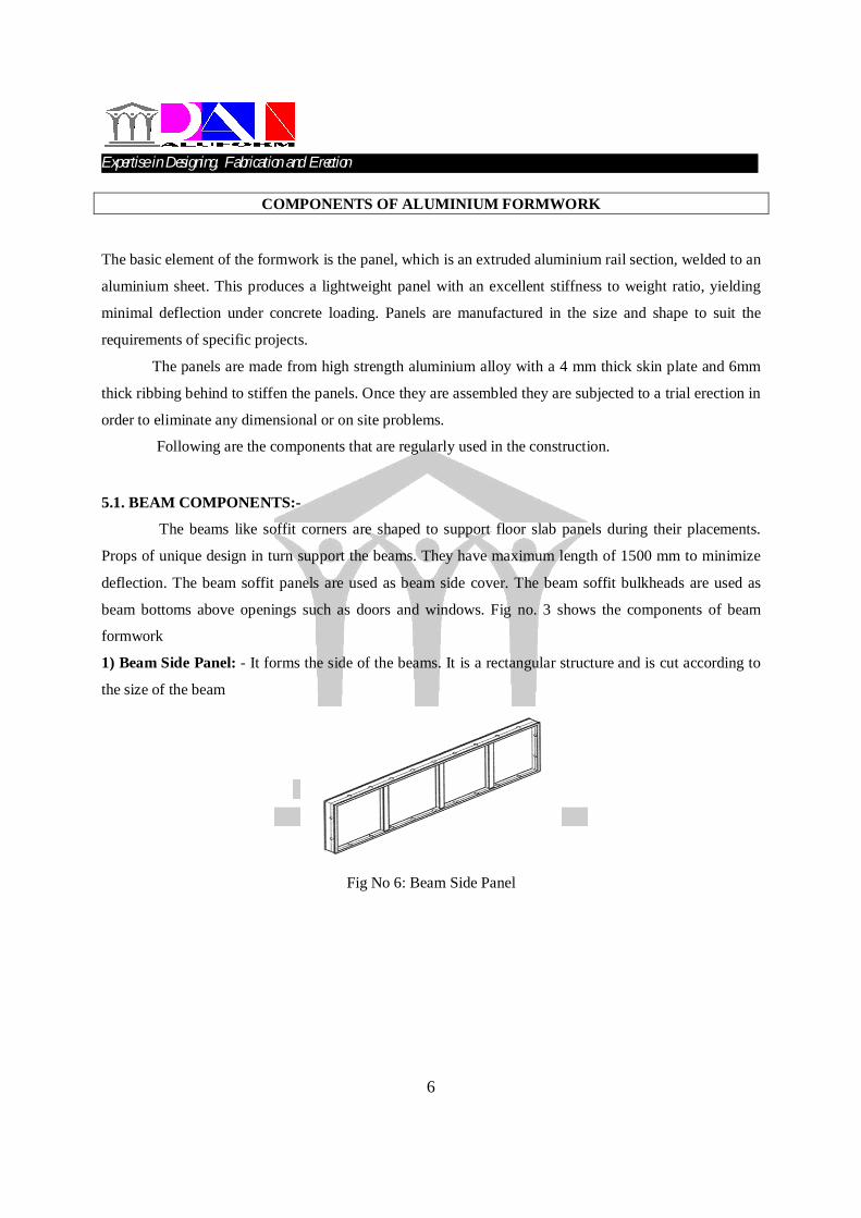
1) Beam Side Panel: - It forms the side of the beams. It is a rectangular structure and is cut according to
the size of the beam
Fig No 6: Beam Side Panel
Expertise in Designing, Fabrication and Erection…………………………………………………………………….
7
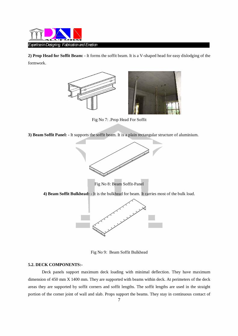
2) Prop Head for Soffit Beam: - It forms the soffit beam. It is a V-shaped head for easy dislodging of the
formwork.
Fig No 7: .Prop Head For Soffit
3) Beam Soffit Panel: - It supports the soffit beam. It is a plain rectangular structure of aluminium.
Fig No 8: Beam Soffit-Panel
4) Beam Soffit Bulkhead: - It is the bulkhead for beam. It carries most of the bulk load.
Fig No 9: Beam Soffit Bulkhead
5.2. DECK COMPONENTS:-
Deck panels support maximum deck loading with minimal deflection. They have maximum
dimension of 450 mm X 1400 mm. They are supported with beams within deck. At perimeters of the deck
areas they are supported by soffit corners and soffit lengths. The soffit lengths are used in the straight
portion of the corner joint of wall and slab. Props support the beams. They stay in continuous contact of
Expertise in Designing, Fabrication and Erection…………………………………………………………………….
8
concrete even while the wall and floor slab panels are being removed. Therefore under standard building
practices the AFS allows for earlier removal of formwork, reduced cycle time and a greater rate of
production. Prop head are fitted on the top of the prop and touch the concrete surface
from the bottom.
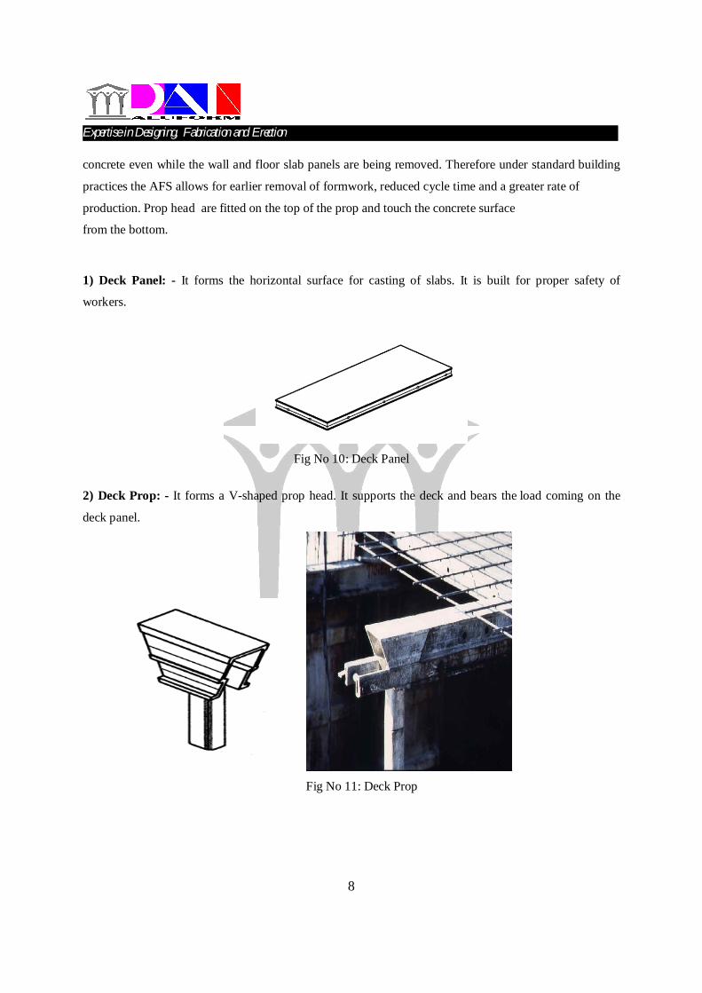
1) Deck Panel: - It forms the horizontal surface for casting of slabs. It is built for proper safety of
workers.
Fig No 10: Deck Panel
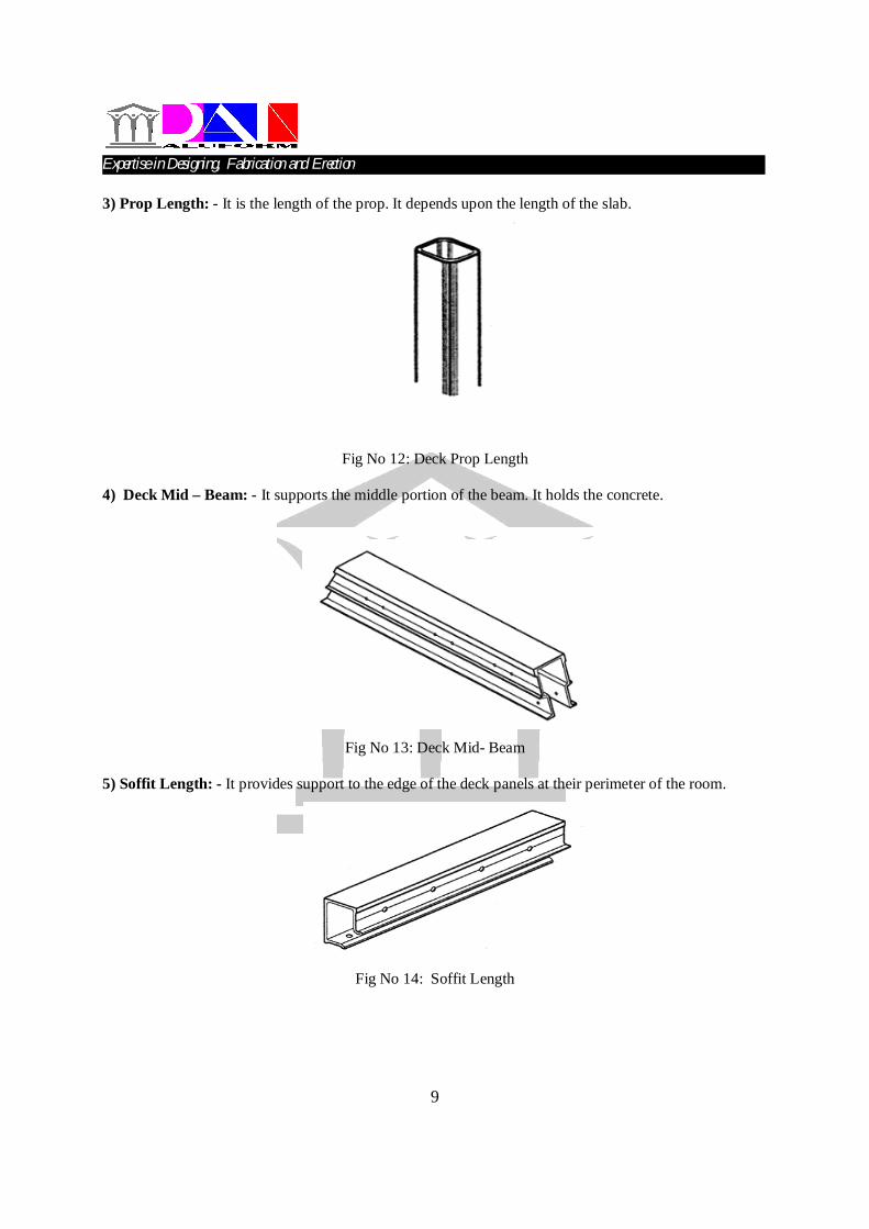
2) Deck Prop: - It forms a V-shaped prop head. It supports the deck and bears the load coming on the
deck panel.
Fig No 11: Deck Prop
Expertise in Designing, Fabrication and Erection…………………………………………………………………….
9
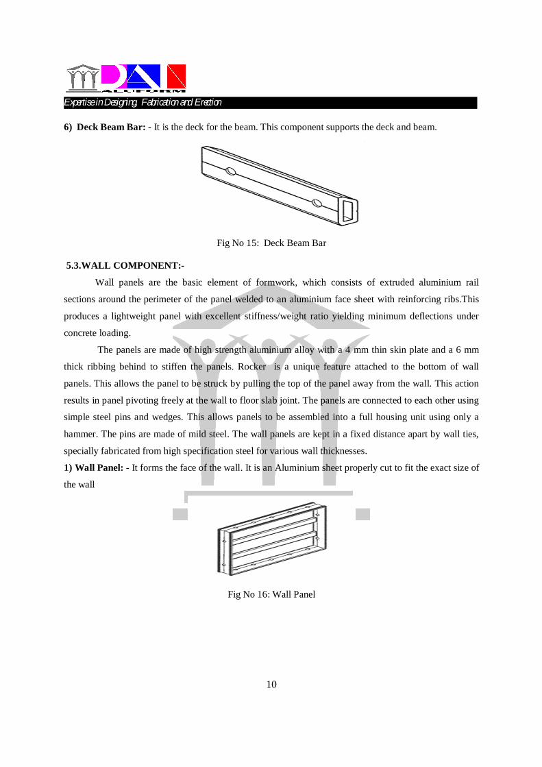
3) Prop Length: - It is the length of the prop. It depends upon the length of the slab.
Fig No 12: Deck Prop Length
4) Deck Mid – Beam: - It supports the middle portion of the beam. It holds the concrete.
Fig No 13: Deck Mid- Beam
5) Soffit Length: - It provides support to the edge of the deck panels at their perimeter of the room.
Fig No 14: Soffit Length
Expertise in Designing, Fabrication and Erection…………………………………………………………………….
10
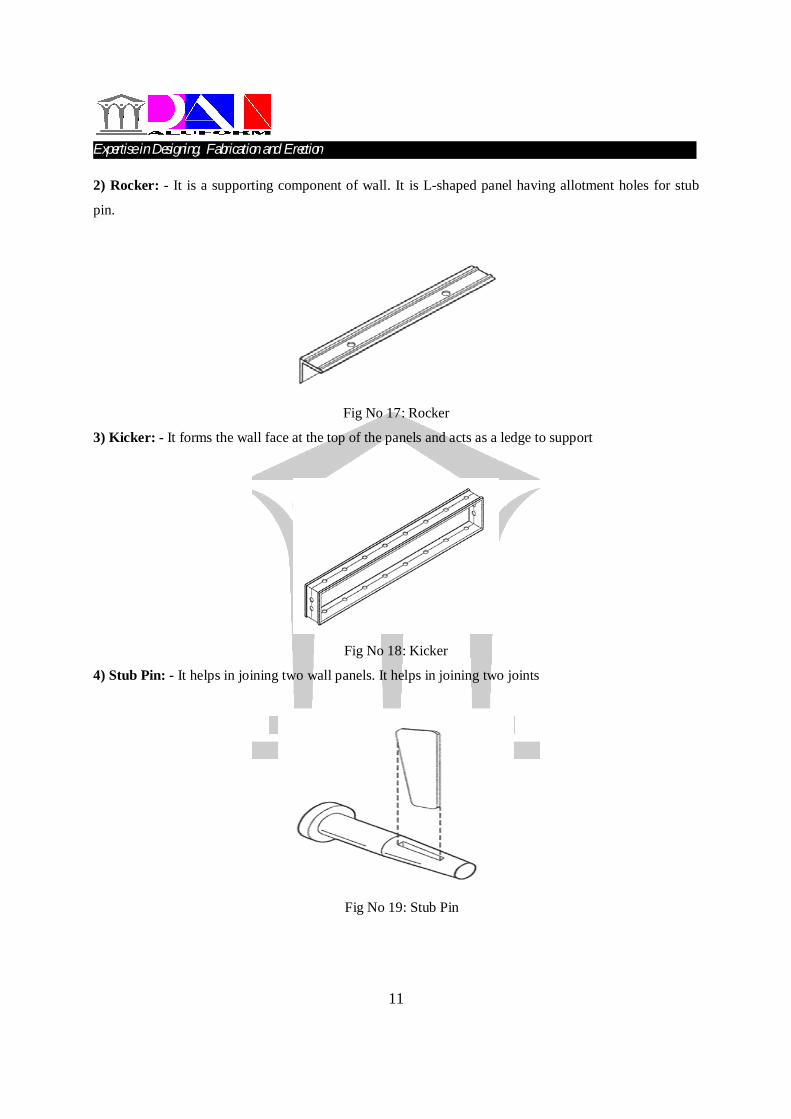
6) Deck Beam Bar: - It is the deck for the beam. This component supports the deck and beam.
Fig No 15: Deck Beam Bar
5.3.WALL COMPONENT:-
Wall panels are the basic element of formwork, which consists of extruded aluminium rail
sections around the perimeter of the panel welded to an aluminium face sheet with reinforcing ribs.This
produces a lightweight panel with excellent stiffness/weight ratio yielding minimum deflections under
concrete loading.
The panels are made of high strength aluminium alloy with a 4 mm thin skin plate and a 6 mm
thick ribbing behind to stiffen the panels. Rocker is a unique feature attached to the bottom of wall
panels. This allows the panel to be struck by pulling the top of the panel away from the wall. This action
results in panel pivoting freely at the wall to floor slab joint. The panels are connected to each other using
simple steel pins and wedges. This allows panels to be assembled into a full housing unit using only a
hammer. The pins are made of mild steel. The wall panels are kept in a fixed distance apart by wall ties,
specially fabricated from high specification steel for various wall thicknesses.
1) Wall Panel: - It forms the face of the wall. It is an Aluminium sheet properly cut to fit the exact size of
the wall
Fig No 16: Wall Panel
Expertise in Designing, Fabrication and Erection…………………………………………………………………….
11
2) Rocker: - It is a supporting component of wall. It is L-shaped panel having allotment holes for stub
pin.
Fig No 17: Rocker
3) Kicker: - It forms the wall face at the top of the panels and acts as a ledge to support
Fig No 18: Kicker
4) Stub Pin: - It helps in joining two wall panels. It helps in joining two joints
Fig No 19: Stub Pin
Expertise in Designing, Fabrication and Erection…………………………………………………………………….
12
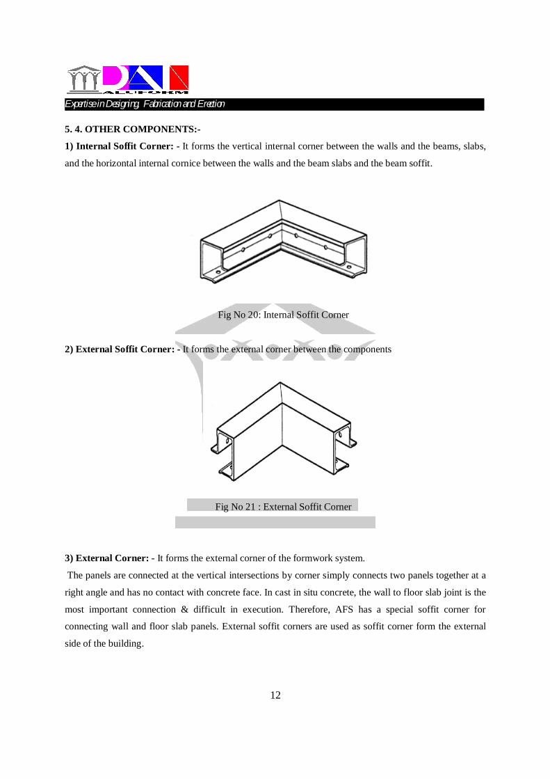
5. 4. OTHER COMPONENTS:-
1) Internal Soffit Corner: - It forms the vertical internal corner between the walls and the beams, slabs,
and the horizontal internal cornice between the walls and the beam slabs and the beam soffit.
Fig No 20: Internal Soffit Corner
2) External Soffit Corner: - It forms the external corner between the components
Fig No 21 : External Soffit Corner
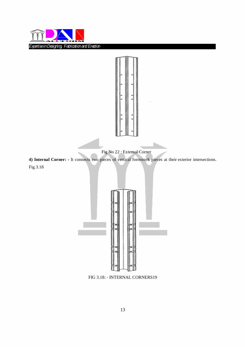
3) External Corner: - It forms the external corner of the formwork system.
The panels are connected at the vertical intersections by corner simply connects two panels together at a
right angle and has no contact with concrete face. In cast in situ concrete, the wall to floor slab joint is the
most important connection & difficult in execution. Therefore, AFS has a special soffit corner for
connecting wall and floor slab panels. External soffit corners are used as soffit corner form the external
side of the building.
Expertise in Designing, Fabrication and Erection…………………………………………………………………….
13
Fig No 22 : External Corner
4) Internal Corner: - It connects two pieces of vertical formwork pieces at their exterior intersections.
Fig 3.18
FIG 3.18: - INTERNAL CORNERS19
Expertise in Designing, Fabrication and Erection…………………………………………………………………….
14
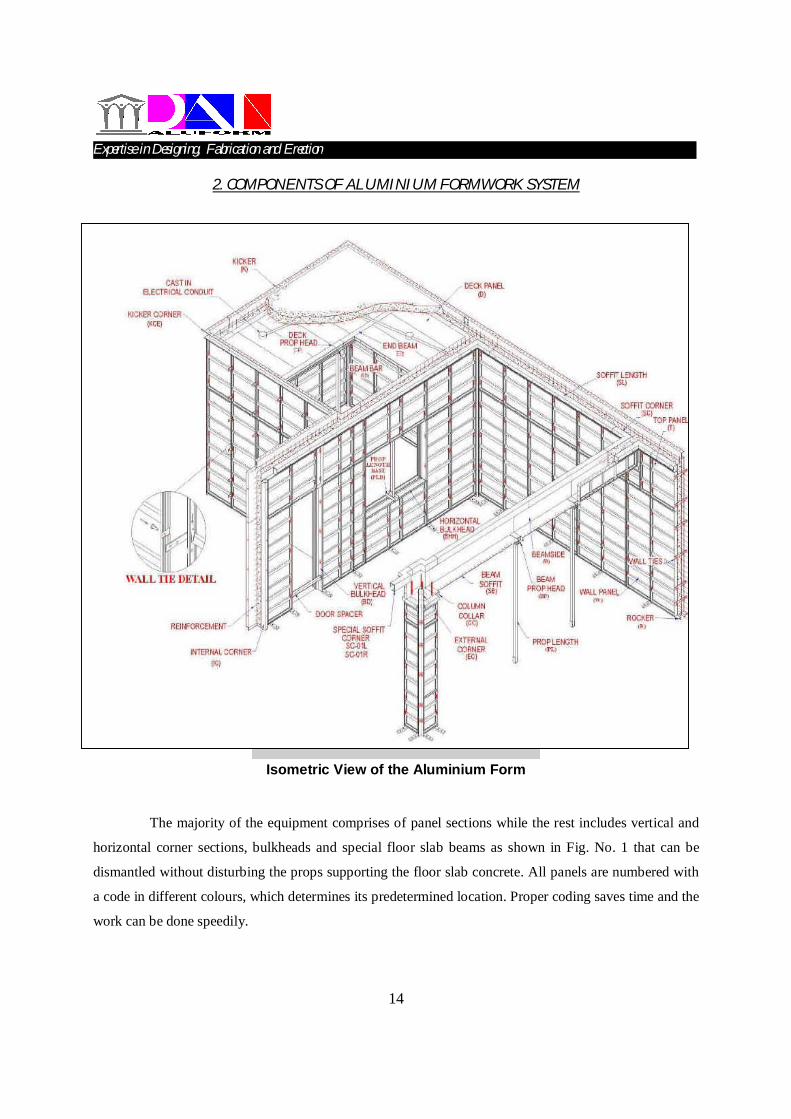
2. COMPONENTS OF ALUMINIUM FORMWORK SYSTEM
Isometric View of the Aluminium Form
The majority of the equipment comprises of panel sections while the rest includes vertical and
horizontal corner sections, bulkheads and special floor slab beams as shown in Fig. No. 1 that can be
dismantled without disturbing the props supporting the floor slab concrete. All panels are numbered with
a code in different colours, which determines its predetermined location. Proper coding saves time and the
work can be done speedily.
Expertise in Designing, Fabrication and Erection…………………………………………………………………….
15
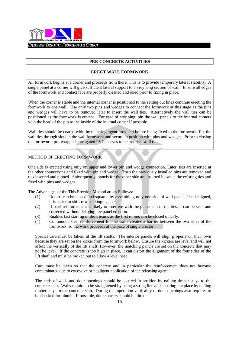
PRE-CONCRETE ACTIVITIES
ERECT WALL FORMWORK
All formwork begins at a corner and proceeds from there. This is to provide temporary lateral stability. A single panel at a corner will give sufficient lateral support to a very long section of wall. Ensure all edges of the formwork and contact face are properly cleaned and oiled prior to fixing in place. When the corner is stable and the internal corner is positioned to the setting out lines continue erecting the formwork to one wall. Use only two pins and wedges to connect the formwork at this stage as the pins and wedges will have to be removed later to insert the wall ties. Alternatively the wall ties can be positioned as the formwork is erected. For ease of stripping, pin the wall panels to the internal comers with the head of the pin to the inside of the internal comer if possible. Wall ties should be coated with the releasing agent provided before being fixed to the formwork. Fix the wall ties through slots in the wall formwork and secure in position with pins and wedges. Prior to closing the formwork, pre-wrapped corrugated PVC sleeves to be insert in wall tie. METHOD OF ERECTING FORMWORK One side is erected using only on upper and lower pin and wedge connection. Later, ties are inserted at the other connections and fixed with pin and wedge. Then the previously installed pins are removed and ties inserted and pinned. Subsequently, panels for the other side are inserted between the existing ties and fixed with pins and wedges. The Advantages of the This Erection Method are as Follows:
(1) Rooms can be closed and squared by assembling only one side of wall panel. If misaligned, it is easier to shift rows of single panels.
(2) If steel reinforcement is likely to interfere with the placement of the ties, it can be seen and corrected without delaying the panel erection.
(3) Enables fast start up of deck teams as the first rooms can be closed quickly. (4) Continuous steel reinforcement for the walls creates a barrier between the two sides of the
formwork, so the work proceeds at the pace of single erector. Special care must be taken, at the lift shafts. The interior panels will align properly on their own because they are set on the kicker from the formwork below. Ensure the kickers are level and will not affect the vertically of the lift shaft, However, the matching panels are set on the concrete that may not be level. If the concrete is too high in place, it can distort the alignment of the four sides of the lift shaft and must be broken out to allow a level base. Care must be taken so that the concrete and in particular the reinforcement does not become contaminated due to excessive or negligent application of the releasing agent. The ends of walls and door openings should be secured in position by nailing timber stays to the concrete slab. Walls require to be straightened by using a string line and securing the place by nailing timber stays to the concrete slab. During this operation verticality of door openings also requires to be checked for plumb. If possible, door spacers should be fitted.
Expertise in Designing, Fabrication and Erection…………………………………………………………………….
16
Erection Steps : Step 1 : Erection of Internal Corner and adjacent std. Wall Panels with Rockers.
Internal Corner - IC
Std. Wall Panel
Wall Tie
Rocker
Expertise in Designing, Fabrication and Erection…………………………………………………………………….
17
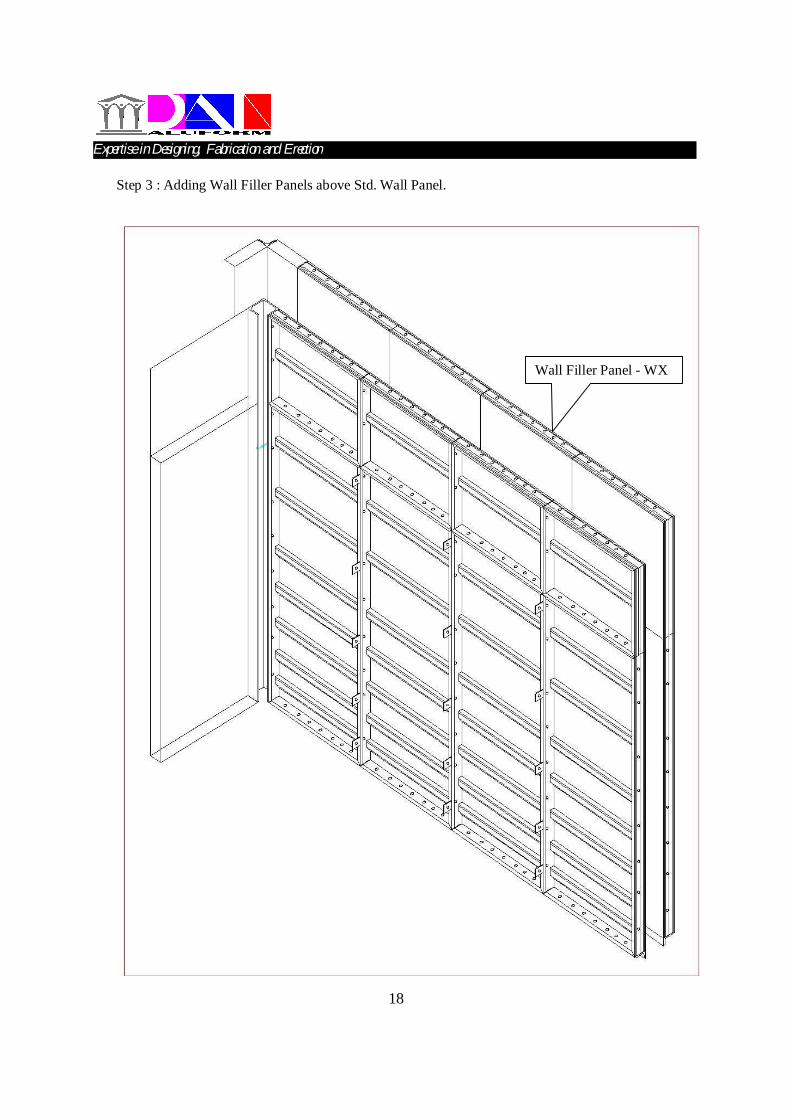
Step 2 : Continuing Std. Wall Panels with Wall Tie.
Expertise in Designing, Fabrication and Erection…………………………………………………………………….
Expertise in Designing, Fabrication and Erection…………………………………………………………………….
19
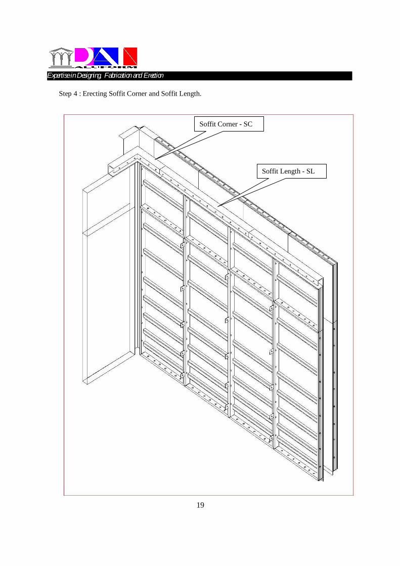
Step 4 : Erecting Soffit Corner and Soffit Length.
Soffit Corner - SC
Soffit Length - SL
Expertise in Designing, Fabrication and Erection…………………………………………………………………….
20
Step 5 : Erecting Deck Panel with the help of Deck Beam and Prop.
End Beam - EB
Deck Panel - D
Deck Prop – DP200
Prop Length – PL
Mid Beam – MB
Deck Pin
Beam Bar BB350
Expertise in Designing, Fabrication and Erection…………………………………………………………………….
21
Step 6 : Erecting Kicker Corner and Kicker on External Wall.
Kicker Corner - KC
Kicker - K
Expertise in Designing, Fabrication and Erection…………………………………………………………………….
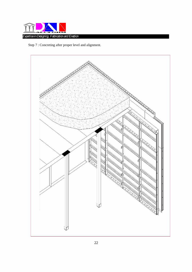
22
Step 7 : Concreting after proper level and alignment.
Expertise in Designing, Fabrication and Erection…………………………………………………………………….
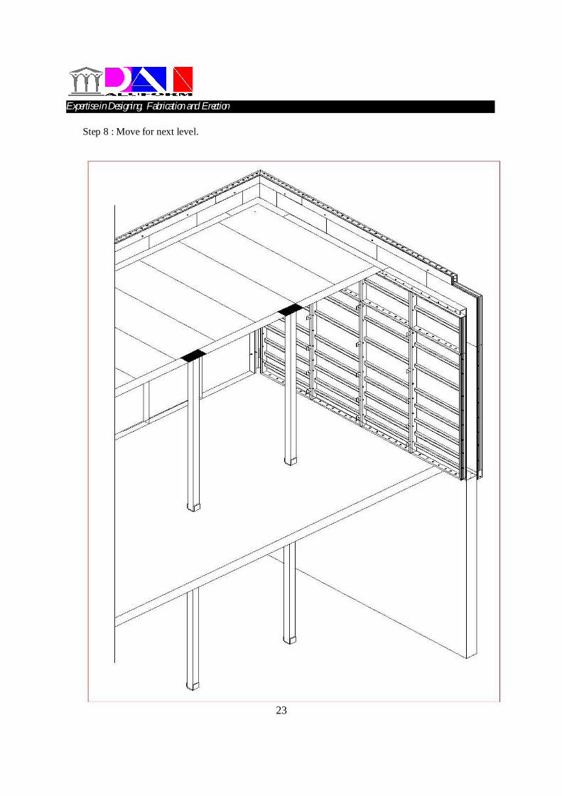
23
Step 8 : Move for next level.
Expertise in Designing, Fabrication and Erection…………………………………………………………………….
24
PRE-CONCRETE ACTIVITIES
ERECT DECK FORMWORK Before fixing in position the soffit length (SL) and soffit corners (SC) should be coated on the contact face plus the top and bottom rails with a release agent. When connecting the soffit lengths and soffit corners to the vertical formwork, the pins should be inserted from the top preventing the possibility of the pin falling out during concreting. After fixing of the soffit lengths the deck panels can be pinned at the corners again ensuring oil has been applied to the edges only. In most cases the deck beams to support the deck formwork, can be assembled on the concrete slab. Lay the beam components on the floor as per the deck layout drawing. Components are held together by pinning BB 350, (Beam Bars) through two adjoining beams with a D.P. 200 (Deck Prop) located between using the 132 mm pin. Fit the prop lengths to the reassembled beam with the shoe of the prop facing in the direction of the beam. This protects the bottom of the prop length when striking the prop. Using the prop lengths lift the beam into position. The beam is held in place by inserting a pin from the beam, through the end of the deck panel already fixed to the corner. Ensure side rails of the Deck beam has been oiled prior to fixing The first panel in a row has to be pinned to the soffit length and the deck Beam. The second panel should be panel to the first deck panel only, (two pins are normally enough). Ensuring the second panel is not fixed to the deck beam will leave sufficient movement in the beam to place the third panel of that row. Fixed the third panel to the second panel and then pined the second panel to the deck beam. Placed the remaining panels in the row using the same method. A numbers of rows can be fixed simultaneously the face of the deck panels on completion can be oiled prior to the placing of the slab reinforcement. On the completion of fitting the deck panels a survey team is required to check the level of all soffit formwork and adjust accordingly.
Expertise in Designing, Fabrication and Erection…………………………………………………………………….
25
PRE-CONCRETE ACTIVITIES
SETTING KICKERS Where there is a continuous vertical wall, e.g. lift shaft, external face of the building etc., a kicker forms the perimeter of the slab and also acts as the connecting compound for the vertical formwork on the next level. After casting of the first level of formwork, two levels of kicker are required, one coming off the previous floor to which the formwork is fixed and the other fixed to the top of the wall formwork which forms the perimeter of the slab. This kicker remains in place after concreting and is used to start the wall form on the next level. Connecting Kickers to Wall Panels Ensure kickers are properly cleaned and oiled prior to fixing in position. To prevent the pin being dislodged during concreting, pins should be inserted in downward direction through the bottom rail of the kicker and top rail of the wall panel. Kickers are manufactured with a 16.5 mm hole, Prior to concreting, a 16mm dia M.S bolt is fixed to the kicker, located tight to hole. This bolt remains fixed to the casted concrete with a flat washer and nut to act as anchor. Aligning Kickers Kickers should be checked for alignment using a string line: A straight kicker will ensure the wall on the next level is also straight. The method used to align kickers Steel vertical soldiers fixed in place using a tie-rod through the cast in PVC sleeve, which will be used later for the fixing of the wall mounted scaffold brackets. Where the end of two kickers meat, a B.K.C. (strap across the top of the kickers) should be used, keeping the two adjoining components flush.
Expertise in Designing, Fabrication and Erection…………………………………………………………………….
26
DURING CONCRETING
STAND BY DURING CONCRETE At least two operators should be on stand by during concreting, to cover both sides of the wall being casted. During concreting the ideal position is slightly in front of the pour, checking pins, wedges and wall ties as the pour is in progress. Pins, wedges or wall ties missing could lead to a movement on the formwork and the possibility of the formwork being damaged. This effected area will then require remedial work after striking of the formwork. Things to look for during concreting: (a) Dislodging of pins/Wedges due to vibration. (b) Beam/Deck props adjacent to drop areas slipping due to vibration. (c) Ensure all bracing at special areas stays intact. (d) Overspill of concrete at window openings etc. Operators should have following things in hand, (e) pins and Wedges (f) Adjustable props (g) Masonry nails (h) Joinery saw and hammer (i) A few lengths of timber for additional bracing ( if required)
Expertise in Designing, Fabrication and Erection…………………………………………………………………….
27
POST CONCRETE ACTIVITIES
STRIKE WALL FORMWORK Normal wall formwork can be strike after 12 hours. Striking times are confirmed on a project, to project basis. Before striking wall formwork ensure the following are removed: a) All timber stays nailed t6o the concrete slab b) Walers (if any) c) Vertical soldiers. d) All pins and wedges from the panels identified for striking. e) Care must be taken when removing pins and wedges on the external and void areas, especially on the safety issue. Also considerable amount of pins and wedges can be lost over a short period of time due to inadequate care taken when removing. Ensure commencement of work on the 250 mm thick walls first therefore enabling commencement of extracting the wall ties as soon as possible. The sooner they are extracted from the wall, less force required and less time consuming. External walls are also critical to enable the progress of installing the scaffold bracket for placing of the formwork on the next level. While removal of the wall ties is in progress ensure they are kept neatly in an appropriate area where they can be prepared for the next level. As soon as the removal of ties is progressing then striking of the formwork can commence. All components must be cleaned as soon as they are removed. The longer the cleaning process is delayed, the more difficult it will be. Wall panels, are designed to be removed by pulling the top of the panel away from the concrete where a rocker is fitted. The rocker at the bottom of a panel enables the panel to pivot against the concrete slab. Where the wall formwork is pinned to a kicker, the panels are removed by pulling the bottom away first. The first panel in a row is the most difficult to remove as it is also held by the adjacent panels. If properly cleaned and oiled prior to concreting and using the panel pullers provided, the panels will come away with ease. The remainder of his wall panels on this will strike easily by breaking the bond to the adjacent panel using the panel puller as mentioned above. The same situation applies to the sleeves as to removal of the wall ties, the sooner they are extracted from the wall the less time consumed. Also less damage will occur therefore maximum uses can be achieved per sleeve. Sleeves are removed by using nose pinch pliers. Ensure the sleeves are being stored in a proper container when removed and returned to the preparation location as they can be prepared for the next use. When moving the formwork to the next area, proper stacking of panels is a clear sign of well run operation. Stacking at the right place and in the right order greatly benefits the following erection work. Striking of the external walls also requires urgent attention to enables the installation of the working platform bracket.
Expertise in Designing, Fabrication and Erection…………………………………………………………………….
28
POST CONCRETE ACTIVITIES
STRIKE DECK FORMWORK Normally deck panels can be struck after 36 hours. Striking times should be confirmed on project, to project basis. The striking begins with the removal of deck beam. Remove the 132 mm pin and the beam bars from the beam, which has been identified for removal. This is followed by removing the pins and wedges from the deck panel’s adjacent panel should be removed first after removing the pins and wedges from the panel to be removed. The Deck beam can now be taken out. As the first panel in row rests on the support lip of the soffit length, the adjacent panel should be removed first. After removing the pins and wedges from the panel to be removed, a panel puller can be used to break the bond from the adjacent formwork. Where there is no deck beam supports and the panels, span from wall to wall, one wall will have the supporting lip of the soffit length removed. Pins and wedges only to be removed from the component that is to be struck. Deck panels remain in place longer than wall panels and will not come away easily unless proper cleaning and oiling is done during the erection process. Panels should be cleaned immediately after striking. Consequently the sequence of striking should confirm to the sequence of erection. PROP LENGTHS Whenever the PL’s is to be removed, use a wooden mallet to strike the bottom of the PL in the same direction as the beam and holding the PL with your other hand.
Expertise in Designing, Fabrication and Erection…………………………………………………………………….
Expertise in Designing, Fabrication and Erection…………………………………………………………………….
30
POST CONCRETE ACTIVITIES
STRIKE KICKER FORMWORK Only the kicker pinned to the bottom of the wall panels should be removed. The top kicker will be used for starting the wall formwork on the next floor area. The wall panels are removed. Disconnect the kicker by removing the cast in bolt. This leaves the kicker free to be taken off and prepares for next use by cleaning and oiling. Ensure the cast in bolts are also cleaned by wire brush after each use.
Expertise in Designing, Fabrication and Erection…………………………………………………………………….
31
INSTRUCTIONS
TO BE IMPOSED ON EVERY WORKER
Do not lay bottom panel contact face down when starting a stack Do not drop equipment from any height Do not use panels as ramps, bridges or scaffolds. Do not use hammer and wedge to pull panels together. Do not drive wedge until full length of panels are bought together. Do not use extreme hammer force when installing wedges. Do not erect elements not properly cleaned and oiled
(Deck panel faces are oiled after erection)
SAFETY
(a) Ensure all scaffold brackets are in good condition and have not been damaged since the last
installation. (b) Ensure platform is fully decked out and toe board and hand rail installed. (c) Penetrations holes in the slab for transferring panels must be covered when not in use until
cast with concrete. (d) Any workers working above platform level must wear safety belt attached to a secured
formwork. (e) When removing of the timber batons from the slab after casting ensure no nails have been left
exposed. (f) Pins and wedges to be removed with care especially on the external of the building. (g) Handling of equipment. (h) Formwork not to be stacked on the scaffold.
Expertise in Designing, Fabrication and Erection…………………………………………………………………….
32
SOME TYPICAL STEEL ACCESSORIES
Expertise in Designing, Fabrication and Erection…………………………………………………………………….
33
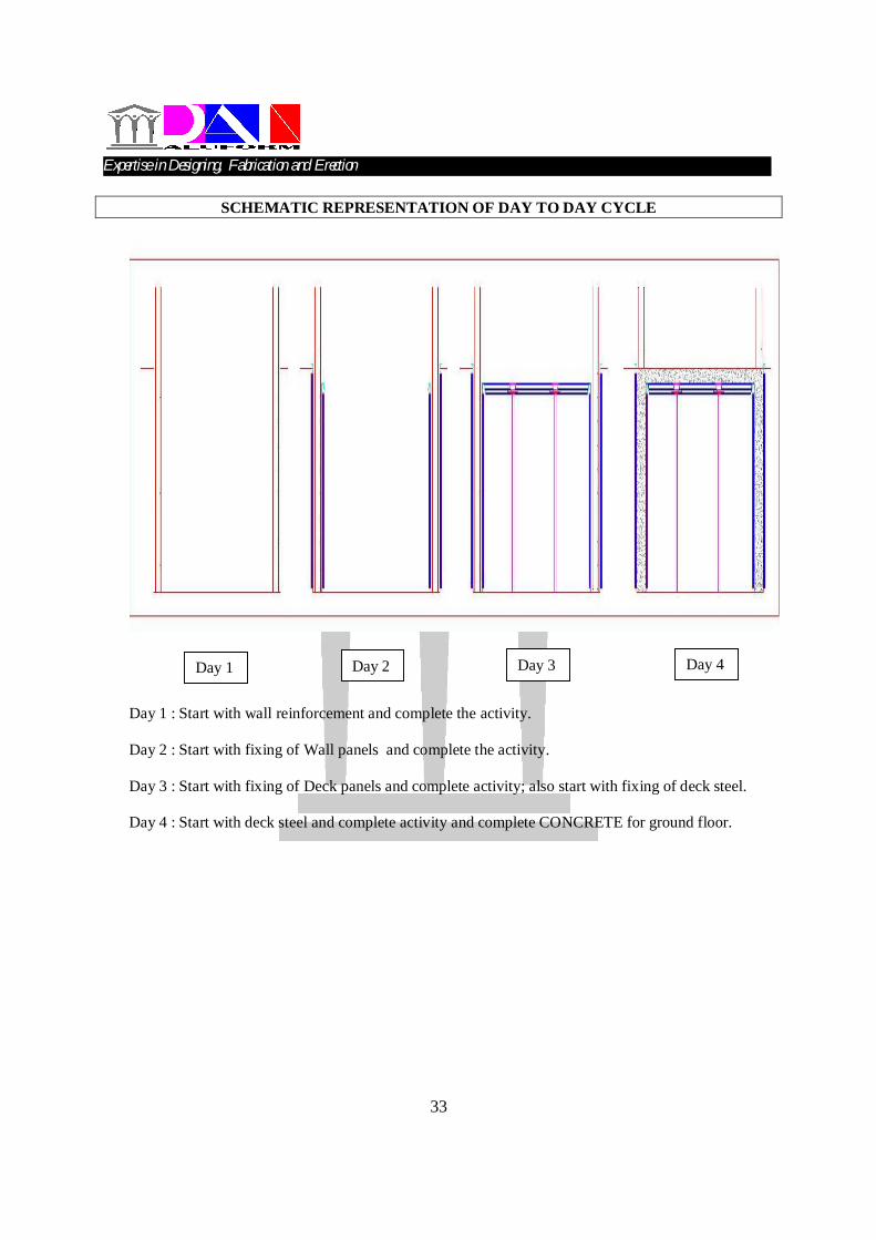
SCHEMATIC REPRESENTATION OF DAY TO DAY CYCLE
Day 1 : Start with wall reinforcement and complete the activity. Day 2 : Start with fixing of Wall panels and complete the activity. Day 3 : Start with fixing of Deck panels and complete activity; also start with fixing of deck steel. Day 4 : Start with deck steel and complete activity and complete CONCRETE for ground floor.
Day 1 Day 2 Day 3 Day 4
Expertise in Designing, Fabrication and Erection…………………………………………………………………….
34
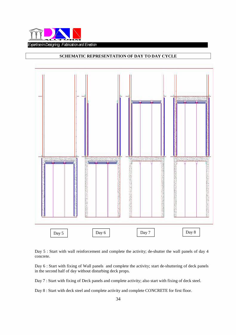
SCHEMATIC REPRESENTATION OF DAY TO DAY CYCLE
Day 5 : Start with wall reinforcement and complete the activity; de-shutter the wall panels of day 4 concrete. Day 6 : Start with fixing of Wall panels and complete the activity; start de-shuttering of deck panels in the second half of day without disturbing deck props. Day 7 : Start with fixing of Deck panels and complete activity; also start with fixing of deck steel. Day 8 : Start with deck steel and complete activity and complete CONCRETE for first floor.
Day 5 Day 6 Day 7 Day 8
Expertise in Designing, Fabrication and Erection…………………………………………………………………….