ALL RIGHTS RESERVED. NO PART OF THIS PUBLICATION MAY BE REPRODUCED OR TRANSMITTED IN ANY FORM OR BY ANY MEANS, INCLUDING PHOTOCOPYING AND RECORDING, WITHOUT THE WRITTEN PERMISSION OF THE COPYRIGHT HOLDER. APPLICATION FOR WHICH SHOULD BE ADDRESSED TO THE PUBLISHER. SUCH WRITTEN PERMISSION MUST ALSO BE OBTAINED BEFORE ANY PART OF THE PUBLICATION IS STORED IN A RETRIEVAL SYSTEM OF ANY NATURE. WARNING: THE DOING OF AN UNATHORIZED ACT IN RELATION TO A COPYRIGHT WORK MAY RESULT IN BOTH CIVIL CLAIM FOR DAMAGES AND CRIMINAL PROSECUTION. FORMWORK PROCEDURES MANUAL 1
Transcript
ALL RIGHTS RESERVED. NO PART OF THIS PUBLICATION MAY BE REPRODUCED OR TRANSMITTED IN ANY FORM OR BY ANY MEANS, INCLUDING PHOTOCOPYING AND RECORDING, WITHOUT THEWRITTEN PERMISSION OF THE COPYRIGHT HOLDER. APPLICATION FOR WHICH SHOULD BE ADDRESSED TO THE PUBLISHER. SUCH WRITTEN PERMISSION MUST ALSO BE OBTAINED BEFORE ANYPART OF THE PUBLICATION IS STORED IN A RETRIEVAL SYSTEM OF ANY NATURE.WARNING: THE DOING OF AN UNATHORIZED ACT IN RELATION TO A COPYRIGHT WORK MAY RESULT IN BOTH CIVIL CLAIM FOR DAMAGES AND CRIMINAL PROSECUTION.
3. Setting Out ……………………………………………………………………………………………………………………………………
FORMWORK PROCEDURES MANUAL
2
3
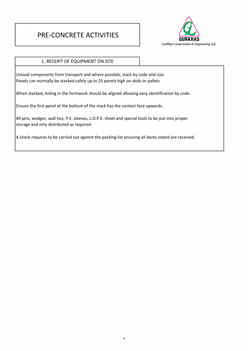
A check requires to be carried out against the packing list ensuring all items stated are received.
All pins, wedges, wall ties, P.E. sleeves, L.D.P.E. sheet and special tools to be put into properstorage and only distributed as required.
1. RECEIPT OF EQUIPMENT ON SITE
Unload components from transport and where possible, stack by code and size.Panels can normally be stacked safely up to 25 panels high on skids or pallets
When stacked, holing in the formwork should be aligned allowing easy identification by code.
Ensure the first panel at the bottom of the stack has the contact face upwards.
PRE-CONCRETE ACTIVITIES
4
Item Ref Delivery No. (D/0)Pallet Ref
No.Date Goods
ReceivedDescription of
GoodsFormwork
M2 ReceivedMFE Representative
’s SignatureClient’s
RepresentativeSi t
Date ofSignatures
1 121046 1005 12th May 2004 Formwork 40.5 14th May 2004
2 121046 1006 12th May 2004 Formwork 37.26 14th May 2004
3 121046 1007 12th May 2004 Formwork 51.45 14th May 2004
4 121046 1008 12th May 2004 Formwork 43.75 14th May 2004
5 121047 1506 14th May 2004 Accessories 0.00 16th May 2004
6 121047 1009 14th May 2004 Formwork 29.64 16th May 2004
7 121047 1507 14th May 2004 Scaffolding 0.00 16th May 2004
8
9
10
11
12
13
14
15
CONFIRMATION OF MATERIALS RECEIVEDPROJECT :Contents of Each Pallet Received as Stated on the Packing List
Client’s Company Chop and Signature of Representativeconfirming the above to be accurate and correct.
Name : ………………………………….Company’s Chop
5
Concrete up to (+6mm high) is acceptable, above 6mm must be chipped to the (correct level).
After concreting, level surveys should also be carried out on the top of the kickers. One reason for structuraldeviation from the centre line can be on a - level kicker. This in turn means the formwork is not plumb.
Kickers are manufactured with a 26mm slotted hole on the face to allow for adjustment after concreting
As with the concrete level survey, proper records of the kicker survey should be kept on file by the allocatedSupervisor.
Also a deviation survey requires to be carried out and kept on file.
PRE-CONCRETE ACTIVITIES
2. LEVEL SURVEYS
A concrete level survey should be taken on all sites and remedial work carried out prior to the erecting offormwork.
All level surveys should be taken from a T.B.M. (Temporary Bench
Mark). A record of all surveys should be kept on file by the allocated
Supervisor.
In certain cases it is good practice to mark the slabs with paint indicating a plus (+) or minus (-) as the survey isbeing conducted. This eliminates unnecessary circulation of paper copies to site personnel, and the Supervisorcan identify at a glance any remedial work required.
High spots along the wall line to be chipped off to the proper level.
Low spots along the wall line should be packed to the required level, using plywood or timber. Packing thecorner and the centre of the wall length to the required level will normally be adequate, as the formworkwhen pinned together will bridge across low spots.
6
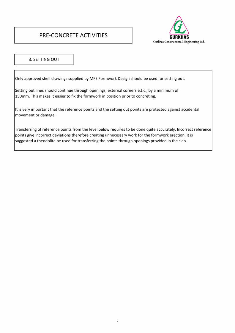
Transferring of reference points from the level below requires to be done quite accurately. Incorrect referencepoints give incorrect deviations therefore creating unnecessary work for the formwork erection. It issuggested a theodolite be used for transferring the points through openings provided in the slab.
PRE-CONCRETE ACTIVITIES
3. SETTING OUT
Only approved shell drawings supplied by MFE Formwork Design should be used for setting out.
Setting out lines should continue through openings, external corners e.t.c., by a minimum of150mm. This makes it easier to fix the formwork in position prior to concreting.
It is very important that the reference points and the setting out points are protected against accidentalmovement or damage.
7
Once the vertical formwork is fixed in position, the external corners should be checked for plumbness. Thiswill determine if further action is required to control the deviation.
In addition to the kicker levels, the formwork can be pulled by using bottle screws and chain blocks. If theformwork requires to be pushed adjustable props can be used.
PRE-CONCRETE ACTIVITIES
4. CONTROL / CORRECTING OF DEVIATIONS
A study of the deviation and kicker level survey should confirm what, if any, corrective action is required.
If the kicker requires adjustment for level, loosen the holding - in bolt by turning anti-clockwise, adjust kickerto the required position and retighten the bolt.
8
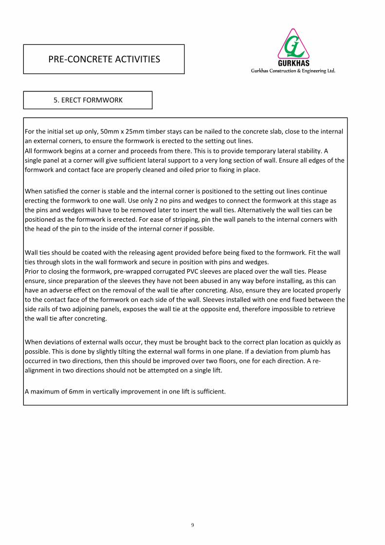
All formwork begins at a corner and proceeds from there. This is to provide temporary lateral stability. Asingle panel at a corner will give sufficient lateral support to a very long section of wall. Ensure all edges of theformwork and contact face are properly cleaned and oiled prior to fixing in place.
When satisfied the corner is stable and the internal corner is positioned to the setting out lines continueerecting the formwork to one wall. Use only 2 no pins and wedges to connect the formwork at this stage asthe pins and wedges will have to be removed later to insert the wall ties. Alternatively the wall ties can bepositioned as the formwork is erected. For ease of stripping, pin the wall panels to the internal corners withthe head of the pin to the inside of the internal corner if possible.
Wall ties should be coated with the releasing agent provided before being fixed to the formwork. Fit the wallties through slots in the wall formwork and secure in position with pins and wedges.Prior to closing the formwork, pre-wrapped corrugated PVC sleeves are placed over the wall ties. Pleaseensure, since preparation of the sleeves they have not been abused in any way before installing, as this canhave an adverse effect on the removal of the wall tie after concreting. Also, ensure they are located properlyto the contact face of the formwork on each side of the wall. Sleeves installed with one end fixed between theside rails of two adjoining panels, exposes the wall tie at the opposite end, therefore impossible to retrievethe wall tie after concreting.
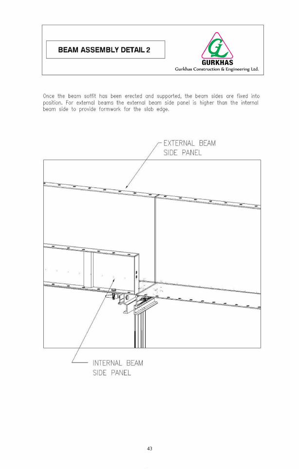
When deviations of external walls occur, they must be brought back to the correct plan location as quickly aspossible. This is done by slightly tilting the external wall forms in one plane. If a deviation from plumb hasoccurred in two directions, then this should be improved over two floors, one for each direction. A re-alignment in two directions should not be attempted on a single lift.
A maximum of 6mm in vertically improvement in one lift is sufficient.
PRE-CONCRETE ACTIVITIES
5. ERECT FORMWORK
For the initial set up only, 50mm x 25mm timber stays can be nailed to the concrete slab, close to the internalan external corners, to ensure the formwork is erected to the setting out lines.
9
(3) Enables fast start up of deck teams as the first rooms can be closed quickly.
(4) Continuous steel reinforcement for the walls, creates a barrier between the two sides of the formwork, sothe work proceeds at the pace of single erector.
Special care must be taken at the lift shafts. The interior panels will align properly on their own because theyare set on the kicker from the formwork below. Ensure the kickers are level and will not affect the verticalityof the lift shaft. However, the matching panels are set on the concrete that may not be level. If the concrete istoo high in place, it can distort the alignment of the four sides of the lift shaft and must be broken out to allowa level base.
Care must be taken so that the concrete and in particular the reinforcement does not become contaminateddue to excessive or negligent application of the releasing agent.
The ends of walls and door openings should be secured in position by nailing timber stays to the concrete slab.Walls require to be straightened by using a string line and securing in place by nailing timber stays to theconcrete slab. During this operation verticality of door openings also requires to be checked for plumb. Wherepossible, door spacers should be fitted.
METHOD OF ERECTING FORMWORK
It is important maximum efficiency to define a sequence of erection to be followed by each team. One side iserected using only on upper and lower pin and wedge connection. Later, ties are inserted at the otherconnections and fixed with pin and wedge. Then the previously installed pins is removed and those tiesinserted and pinned. Subsequently, panels for the other side are inserted between the existing ties and fixedwith pins and wedges.
The Advantages of This Erection Method Are As Follows :-
(1) Rooms can be closed and squared by assembling only one side of wall panels. If misaligned, it is easier toshift rows of single panels.
(2) If steel reinforcement is likely to interfere with the placement of the ties, it can be seen and correctedwithout delaying the panel erection.
10
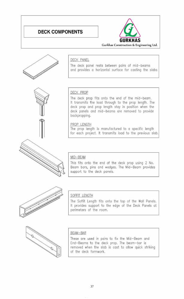
The first panel in a row has to be pinned to the soffit length and the deck beam. The second panel should bepinned to the first deck panel only, (two pins are normally enough).
Ensuring the second panel is not fixed to the deck beam will leave sufficient movement in the beam to placethe third panel of that row. Fix the third panel to the second panel, and then pin the second panel to the deckbeam. Place the remaining panels in the row using the same method.
A numbers of rows can be fixed simultaneously. The face of the deck panels on completion can be oiled priorto the placing of the slab reinforcement.
On the completion of fitting the deck panels a survey team is required to check the level of all soffit formworkand adjust accordingly if required, by shimming the bottom of the PL's.
Components are held together by pinning BB 350 (Beam Bars) through two adjoining beams with a D.P. 200(Deck Prop) located between using the 132mm pin.
Fit the prop lengths to the preassembled beam with the shoe of the prop facing in the direction of the beam.This protects the bottom of the prop length when striking the prop.
Using the prop lengths lift the beam into position. The beam is held in place by inserting a pin from the beam,through the end of the deck panel already fixed to the corner.
Ensure side rails of the Deck beam has been oiled prior to fixing.
PRE-CONCRETE ACTIVITIES
6. ERECT DECK FORMWORK
Before fixing in position the soffit lengths (SL) and soffit corners (SC) should be coated on the contact face plusthe top and bottom rails with a release agent.
When connecting the soffit lengths and soffit corners to the vertical formwork, the pins should be insertedfrom the top prevent the possibility of the pin falling out during concreting. After fixing of the soffit lengthsthe deck panels can be pinned at the corners again ensuring oil has been applied to the edges only.
In most cases the deck beams to support the deck formwork, can be assembled on the concrete slab. Lay thebeam components on the floor as per the deck layout drawing.
11
The method used to align kickers.
Steel vertical soldiers fixed in place using a tie-rod, through the cast in PVC sleeve, which will be used later forthe fixing of the wall mounted scaffold brackets.
Where the end of two kickers meat, a B.K.S. (strap across the top of the kickers) should be used, keeping thetwo adjoining components flush.
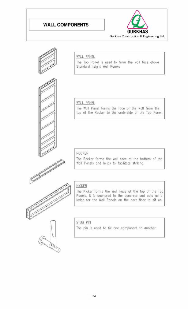
Connecting Kickers To Wall Panels
Ensure kickers are properly cleaned and oiled prior to fixing in position. To prevent the pin being dislodgedduring concreting, pins should be inserted in a downward direction through the bottom rail of the kicker andtop rail of the wall panel.
Kickers are manufactured with a 26mm x 16.5m vertical slotted hole. Prior to concreting, a 16mm dia M.S boltis fixed to the kicker, located tight to the bottom of the slot. This bolt remains fixed to the casted concretewith a flat washer and nut to act as anchor. After concreting the slotted hole allows for an adjustment ifrequired for improvement on the level of the kicker which also controls the verticality of the formwork.
Aligning Kickers
Kickers should be checked for alignment using a string line : A straight kicker will ensure the wall on the nextlevel is also straight.
PRE-CONCRETE ACTIVITIES
Where there is a continuous vertical wall, e.g. lift shaft, external face of the building etc., a kicker forms theperimeter of the slab and also acts as the connecting component for the vertical formwork on the next level.
After casting of the first level of formwork, two levels of kicker are required, one coming off the previous floorto which the formwork is fixed and the other fixed to the top of the wall formwork which forms the perimeterof the slab.This kicker remains in place after concreting and is used to start the wall form on the next level.
7. SETTING KICKERS
12
8. PRE-POUR CHECK LIST
FLOOR LEVEL & SECTION:
Pre-pour check Items
Acceptable : YES: NO:
1 All Formwork has been cleaned and coated with an approved release agent YES: NO:2 All Flat Wall Ties installed. YES: NO:3 All P.E. wall tie sleeves correctly installed YES: NO:4 External & internal wall vertically adjusted accordingly YES: NO:5 Verticality and alignment of Door openings YES: NO:6 Alignment of all internal walls YES: NO:7 Check all required Pins and Wedges are installed and secure YES: NO:8 Verticality of all Prop lengths YES: NO:9 Ensure there is no vertical movement in the Prop lengths YES: NO:
10 Slab soffit formwork level YES: NO:11 Door spacers installed as per Drawings issued YES: NO:12 Alignment Walers installed as per Drawings issued YES: NO:13 Vertical Soldiers installed as per Drawings issued YES: NO:14 All Kickers have been lined and adjusted accordingly YES: NO:15 All Kickers Bolts installed correctly YES: NO:16 All Rockers have been installed YES: NO:17 All excessive spaces between Rocker and floor level have been sealed YES: NO:18 Ensure all working platform brackets are securely fastened to the concrete structure YES: NO:
Inspected By: (Name) Signature)
Remark:
Company :
Date :
PROJECT:
DATE:
13
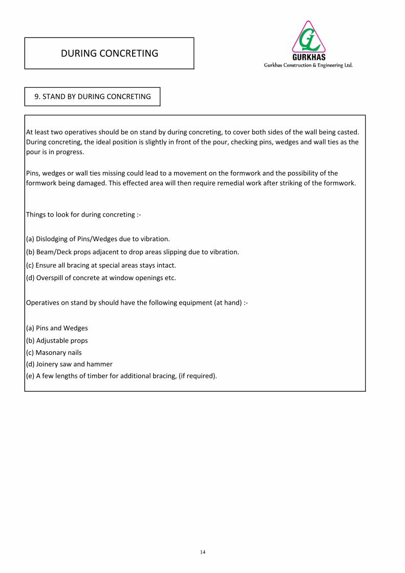
(b) Adjustable props
(c) Masonary nails(d) Joinery saw and hammer(e) A few lengths of timber for additional bracing, (if required).
(a) Pins and Wedges
At least two operatives should be on stand by during concreting, to cover both sides of the wall being casted.During concreting, the ideal position is slightly in front of the pour, checking pins, wedges and wall ties as thepour is in progress.
Pins, wedges or wall ties missing could lead to a movement on the formwork and the possibility of theformwork being damaged. This effected area will then require remedial work after striking of the formwork.
Operatives on stand by should have the following equipment (at hand) :-
Things to look for during concreting :-
(a) Dislodging of Pins/Wedges due to vibration.
(b) Beam/Deck props adjacent to drop areas slipping due to vibration.
(c) Ensure all bracing at special areas stays intact.
(d) Overspill of concrete at window openings etc.
DURING CONCRETING
9. STAND BY DURING CONCRETING
14
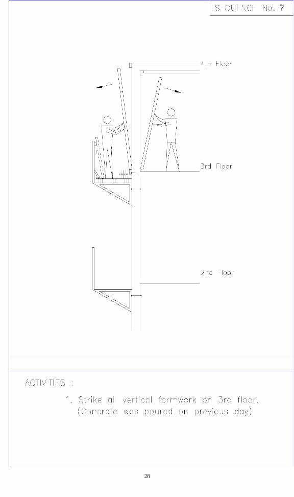
(a) All timber stays nailed to the concrete slab.(b) Walers (if any).(c) Vertical soldiers.(d) All pins and wedges from the panels identified for striking.
Ensure commencement of work on the thickest walls first therefore enabling commencement of extractingthe wall ties as soon as possible. The wall ties can be removed before the removal of the formwork. Thesooner they are extracted from the wall, less force required and less time consuming.
External walls are also critical to enable the progress of installing the scaffold bracket for placing of theformwork on the next level. While removal of the wall ties is in progress ensure they are kept neatly in anappropriate area where they can be prepared for the next level.
As soon as the removal of ties is progressing then striking of the formwork can commence.
All components must be cleaned as soon as they are removed. The longer the cleaning process is delayed, themore difficult it will be. Wall panels are designed to be struck by pulling the top of the panel away from theconcrete where a rocker is fitted.
The rocker at the bottom of a panel enables the panel to pivot about a point against the concrete slab. Wherethe wall formwork is pinned to a kicker, the panels are removed by pulling the bottom away first.
POST CONCRETE ACTIVITIES
10. STRIKE WALL FORMWORK
Normally wall formwork can be struck after 12 hours. Striking times are confirmed on a project to projectbasis.
Before striking wall formwork ensure the following are removed :-
(e) Care must be taken when removing pins and wedges on the external and void areas, especially on thesafety issue. Also considerable amount of pins and wedges can be lost over a short period of time due toinadequate care taken when removing.
15
Sleeves are removed by using long nose pinch pliers. Ensure the sleeves are being stored in a proper containerwhen removed and returned to the preparation location as they can be prepared for the next use.
When moving the formwork to the next area, proper stacking of panels is a clear sign of a well run operation.Stacking at the right place and in the right order greatly benefits the following erection work, and preventsclutter that impedes all activities.
Striking of the external walls also requires urgent attention to enable the installation of the working platformbracket.
The first panel in a row is the most difficult to remove as it is also held by the adjacent panels. If properlycleaned and oiled prior to concreting and using the panel pullers provided, the panels will come away withease.The remainder of the wall panels on this wall will strike easily by breaking the bond to the adjacentpanel using the panel puller as mentioned above.
To strike internal corners the wall ties are removed first as the wall ties prevent the removal of the internalcorner.
As the wall panels are being removed, removal of the sleeves can commence. The same situation applies tothe sleeves as to removal of the wall ties, the sooner they are extracted from the wall the less time consumed.Also less damage will occur therefore maximum uses can be achieved per sleeve.
16
The Deck beam can now be taken out.
Deck panels remain in place longer than wall panels and will not come away easily unless proper cleaning andoiling is done during the erection process. Panels should be cleaned immediately after striking.
Consequently the sequence of striking should confirm to the sequence of erection.
PROP
Whenever the PL's is to be removed, use a wooden mallet to strike the bottom of the PL in the same directionas the beam and holding the PL with your other hand.
Pins and wedges only to be removed on the identified component that is to be struck.
LENGTHS
Normally deck panels can be struck after 36 hours. Striking times should be confirmed on a project to projectbasis.The striking begins with the removal of deck beam. Remove the 132mm pin and the beam bars from the beamwhich has been identified for removal.This is followed by removing the pins and wedges from the deck panels adjacent to the deck beam to beremoved.
As the first panel in a row rests on the support lip of the soffit length, the adjacent panel should be removedfirst. After removing the pins and wedges from the panel to be removed, a panel puller can be used to breakthe bond from the adjacent formwork.
Where there is no deck beam supports and the panels span from wall to wall, one wall will have thesupporting lip of the soffit length removed.
POST CONCRETE ACTIVITIES
11. STRIKE DECK FORMWORK
17
(c) Raised through slots specially formed in the floor slab for this purpose. Once they have served theirpurpose they are closed by casting in a concrete filler.
StrikingOnce cleaned and transported to the next point of erection, panels should be stacked at the right place and inthe right order.Proper stacking is a clear sign of a well managed operation and greatly aids the next sequence of erection aswell as preventing clutter and impeding other activities.
It is usually best to clean panels in the area where they are struck.
TransportingThere are 3 basic methods recommended when transporting to the next floor level :-
(a) The heaviest and longest which is full height wall panels can be carried up the nearest stairway.
(b) Passed up through void areas.
POST CONCRETING ACTIVITIES
12. CLEAN, TRANSPORT AND STACK FORMWORK
CleaningAll components should be cleaned with scrapers and wire brushes as soon as they are struck. Wire brush is tobe used on side rails only.The longer cleaning is delayed, the more difficult the task will be.
18
13. STRIKE KICKER FORMWORK
Only the kicker pinned to the bottom of the wall panels should be struck. The top kicker will be used forstarting the wall formwork on the next floor level.
Once the wall panels are removed, disconnect the lower kicker, remove the cast in bolt. This leaves the kickerfree to be taken off and prepared of reuses. i.e. cleaned and oiled.Ensure the cast in bolts are also cleaned by wire brush after each use.
Each level of kicker will "leap-frog" up the building.
POST CONCRETING ACTIVITIES
19
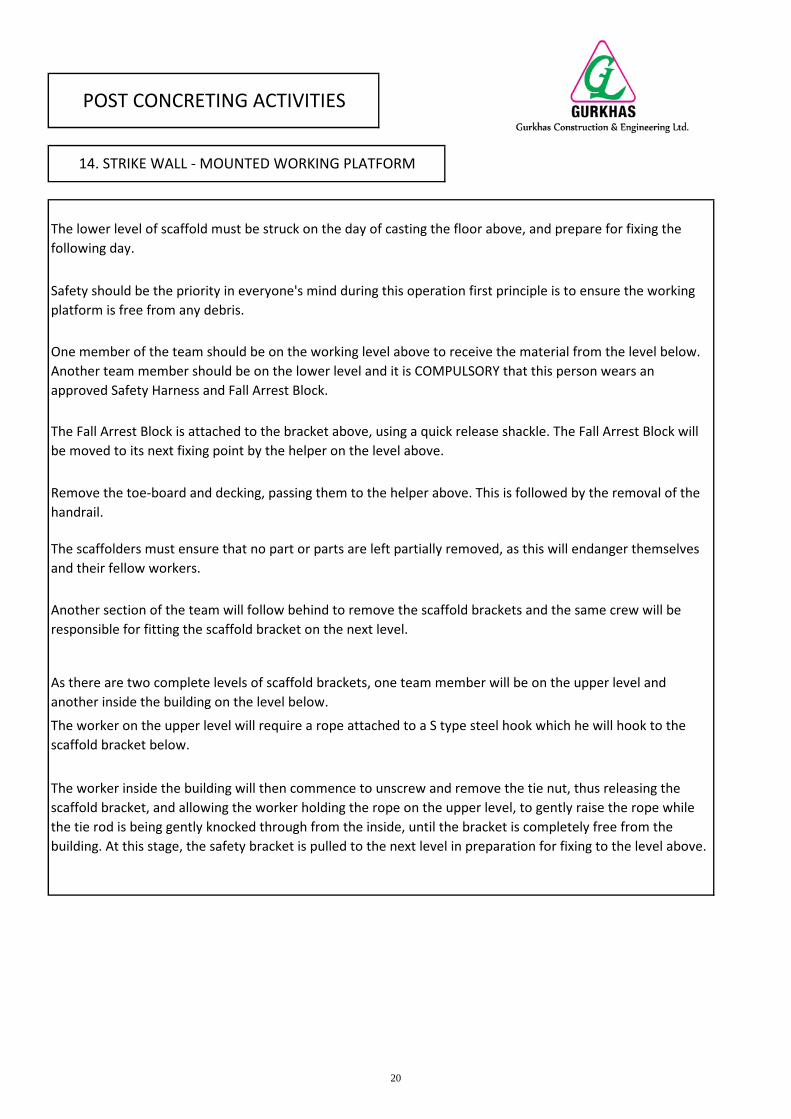
As there are two complete levels of scaffold brackets, one team member will be on the upper level andanother inside the building on the level below.
The worker on the upper level will require a rope attached to a S type steel hook which he will hook to thescaffold bracket below.
The worker inside the building will then commence to unscrew and remove the tie nut, thus releasing thescaffold bracket, and allowing the worker holding the rope on the upper level, to gently raise the rope whilethe tie rod is being gently knocked through from the inside, until the bracket is completely free from thebuilding. At this stage, the safety bracket is pulled to the next level in preparation for fixing to the level above.
The Fall Arrest Block is attached to the bracket above, using a quick release shackle. The Fall Arrest Block willbe moved to its next fixing point by the helper on the level above.
Remove the toe-board and decking, passing them to the helper above. This is followed by the removal of thehandrail.
The scaffolders must ensure that no part or parts are left partially removed, as this will endanger themselvesand their fellow workers.
Another section of the team will follow behind to remove the scaffold brackets and the same crew will beresponsible for fitting the scaffold bracket on the next level.
POST CONCRETING ACTIVITIES
14. STRIKE WALL - MOUNTED WORKING PLATFORM
The lower level of scaffold must be struck on the day of casting the floor above, and prepare for fixing thefollowing day.
Safety should be the priority in everyone's mind during this operation first principle is to ensure the workingplatform is free from any debris.
One member of the team should be on the working level above to receive the material from the level below.Another team member should be on the lower level and it is COMPULSORY that this person wears anapproved Safety Harness and Fall Arrest Block.
20
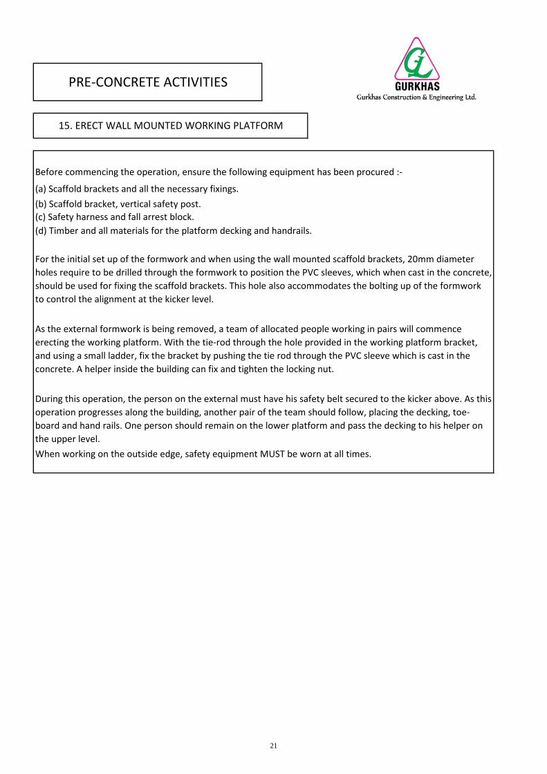
When working on the outside edge, safety equipment MUST be worn at all times.
For the initial set up of the formwork and when using the wall mounted scaffold brackets, 20mm diameterholes require to be drilled through the formwork to position the PVC sleeves, which when cast in the concrete,should be used for fixing the scaffold brackets. This hole also accommodates the bolting up of the formworkto control the alignment at the kicker level.
As the external formwork is being removed, a team of allocated people working in pairs will commenceerecting the working platform. With the tie-rod through the hole provided in the working platform bracket,and using a small ladder, fix the bracket by pushing the tie rod through the PVC sleeve which is cast in theconcrete. A helper inside the building can fix and tighten the locking nut.
During this operation, the person on the external must have his safety belt secured to the kicker above. As thisoperation progresses along the building, another pair of the team should follow, placing the decking, toe-board and hand rails. One person should remain on the lower platform and pass the decking to his helper onthe upper level.
Before commencing the operation, ensure the following equipment has been procured :-
(a) Scaffold brackets and all the necessary fixings.(b) Scaffold bracket, vertical safety post.(c) Safety harness and fall arrest block.(d) Timber and all materials for the platform decking and handrails.
PRE-CONCRETE ACTIVITIES
15. ERECT WALL MOUNTED WORKING PLATFORM
21
22
23
24
25
26
27
28
29
30
31
* Do not lay bottom panel contact face down, when starting a stack
* Do not drop equipment from any height
* Do not use panels as ramps, bridges or scaffold
* Do not use hammer and wedge to pull panels together
* Do not drive wedge until full length of panels are butted together
* Do not use extreme hammer force when installing wedges
* Do not erect elements not properly cleaned and oiled
(Deck panel faces are oiled after erection)
SAFETY
(b) Ensure platform is fully decked out and toe-board and handrail installed.
(h) Formwork not to be stacked on the scaffold.
(a) Ensure all scaffold brackets are in good condition and have not been damaged since the last installation.
(c) Penetration holes in the slab for transferring panels must be covered when not in use until cast withconcrete.(d) Any workers working above platform level must wear safety belt attached to a secured formworkcomponent or the wall steel.(e) When removing of the timber batons from the floor after casting ensure no nails have been left exposed.(f) Pins and wedges to be removed with care especially on the external of the building. (g) Handling ofequipment.
INSTRUCTIONS
17. TO BE IMPOSED ON EVERY WORKER, ARE THE THEFOLLOWING THINGS NOT TO BE DONE
32
(a) Formwork Erection Team (section 5 & 6)(b) Formwork Striking Team (section 10 & 11) (c) Working Platform/Safety Team (section 14 - 16)(d) Alignment Team (section 4 & 7)(e) Kicker Team (section 7 & 13)(f) Survey Team (section 2 & 3)
The work involved in using MFE System Formwork is segregated into duties for specified teams of workers aslisted below. Each team is responsible for following the correct procedures as laid out in the previous sections.