FORTRAN PROGRAM FOR COMPUTING COORDINATES OF CIRCULAR ARC SINGLE AND TANDEM TURBOMACHINERY BLADE SECTIQNS ON A PLANE by Willium D. McNully und Jumes E. Crouse Lewis Resemch Center Cleuehnd, Ohio 441 35 NATIONAL AERONAUTICS AND SPACE ADMINISTRATION WASHINGTON, D. C. NOVEMBER 1970 https://ntrs.nasa.gov/search.jsp?R=19710000937 2018-06-30T11:44:46+00:00Z
Transcript
FORTRAN PROGRAM FOR COMPUTING COORDINATES OF CIRCULAR ARC SINGLE A N D TANDEM TURBOMACHINERY BLADE SECTIQNS ON A PLANE
by Willium D. McNully und Jumes E. Crouse
Lewis Resemch Center Cleuehnd, Ohio 441 35
N A T I O N A L A E R O N A U T I C S A N D SPACE A D M I N I S T R A T I O N W A S H I N G T O N , D. C. NOVEMBER 1970
National Aeronautics and Space Administration Washington, D. C. 20546
___ __ - __ . - . . . . . ~ ~ .-
~ 5. Supplementary Notes
5. Report Date November 1970
6. Performing Organization Code
8. Performing Organization Report No.
-... - - E-5555
10. Work Unit No.
~. ~ ~ . . . 11. Contract or Grant No.
. - . - . 13. Type of Report and Period Covered
Technical Note - __ ~ .
14. Sponsoring Agency Code
. _ _ ~ __ ~- - - . . _ - _ 16. Abstract
A FORTRAN IV program is presented which computes and plots coordinates for circular a r c blade sections on a plane. 5 segments can be designed. arrangement of segments on the plane is a function of the input parameters. These parameters a r e overall blade section quantities such as chord, camber, and solidity, as wel l as individual blade segment parameters such as chord, camber, gap between blade segments, overlap of seg- ments, maximum thickness, and leading- and trailing-edge radii.
Either single blade sections o r tandem blade sections with up to Surfaces of blade segments consist of single circular a r c s . The
~ - _ _ - . 17. Key Words (Suggested by Author(s) )
Turbomachinery blade sections; Blade design; Circular a r c blades; Single blade sections; Tandem blade sections
-_I__ .- - _ _ 19. Security Classif. (of this report) I 20. Security Classif. (
18. Distribution Statement
Unclassified - unlimited
*For sale by the Clearinghouse for Federal Scientific and Technical Information Springfield, Virginia 221 51
FORTRAN PROGRAM FOR COMPUTING COORDINATES OF CIRCULAR ARC
SINGLE AND TANDEM TURBOMACHINERY BLADE SECTIONS ON A PLANE
by William D. McNaIly and James E. Crouse
Lewis Research Center
SUMMARY
A FORTRAN IV computer program is presented which computes and plots coordi- nates for circular a r c blade sections on a plane. Either single blade sections or tandem blades sections with up to 5 segments per blade section can be designed. blade segments consist of single circular a rcs . The arrangement of blade segments with respect to each other (for tandem blades) depends on the input parameters that specify gap, overlap, and convergence between the segments.
Input is brief and can be altered rapidly. Input parameters describing the overall blade section include chord, camber, solidity, and inlet blade angle. Input to describe individual segments of the blade section include chord, camber, gap between adjacent segment and local segment, overlap of segments, maximum segment thickness, and radii of segment leading- and trailing-edge circles. Output consists of three main parts: (1) coordinates of individual segments suitable for making machine drawings, (2) geo- metrical input for companion blade-to-blade ideal flow programs, and (3) a Calcomp plot of the computed blade section in cascade a t the input blade angle. All par ts of the program except the plot routines a r e in general FORTRAN IV code and could be easily transferred to other IBM equipment. The plot routines, a short but important part of the output procedures, use a NASA Lewis code and would require recoding for use on other equipment.
This report includes a listing of the FORTRAN IV computer program, with an ex- planation of the input required and the output generated. Numerical examples a r e a lso included. report does not include derivation or explanation of the equations on which the program is based.
Surfaces of
Running t imes a r e about 1/4 minute per data set on IBM 7094 equipment. The
INTRODUCTION
Specialized airfoil shapes are needed for todays highly loaded, high- speed compres- so r s and turbines t o avoid choking and premature separation. clude single segment airfoils, airfoils with slots, and multiple segment airfoils in a tandem arrangement.
Many of the single and tandem blade designs being studied have airfoil surfaces con- sisting of single circular a rcs . The computation of geometry for such airfoils, particu- larly when placed in a tandem arrangement with controlled slot parameters, is compli- cated by the geometric calculations.
This report describes a computer program for generating coordinates for circular a r c airfoil shapes. One blade section is designed for each set of input data. A blade section consists of one cut through a blade at a given radius from the axis of rotation. The blade section may be composed of just one segment, or it may be a tandem section with two to five segments. The arrangement of blade segments with respect to each other (for tandem blades) depends on input parameters that specify gap, overlap, and conver- gence between the segments. The program does not provide radial stacking of blade sections, since only one section is designed for each se t of data.
e te rs describing the overall blade section and the individual blade segments. Output consists principally of blade coordinates usable in other programs for the study of ideal flow and boundary layer. Output a lso includes coordinates usable for drafting or ma- chining, as well as a view of the blade in cascade in the form of a Calcomp plot.
One of the principal uses of such a program is in conjunction with other computer programs for the analytical study of the performance and flow through turbomachine blading. This program permits the user to quickly generate and visualize circular a r c blade shapes. The procedures of references 1 to 4 a r e then used to calculate velocities and streamlines on blade-to-blade stream surfaces of selected designs. The program of reference 5 calculates boundary-layer parameters from known flow velocity distribu- tions, and finally a program based on reference 6 calculates turbomachine losses from boundary-layer parameters at the blade trailing edge. These programs give the engi- neer the ability to investigate blade shapes by testing them analytically in a computer experiment.
This report includes a listing of the program and a description of its input and out- put. The development of equations for the program is lengthy and wi l l not be included. Internal program variables a r e not defined unless they a r e part of the input or output. Numerical examples a r e included to illustrate typical input values and the form in which output is given.
Shapes under study in-
-
Input is brief and can be prepared quickly. It consists entirely of geometric param-
2 E-5555
SYMBOLS
C
F
G
L
R
Rb RI
RO
S
TC
TM
Z
AK
Kin e 5
cp
blade segment chord (fig. 3), f t ; m
ratio of gap at inlet of channel between blade segments to gap at outlet of channel (figs. 3 and 12)
gap between blade segments (figs. 3 and 12), f t ; m
overlap between blade segments (figs. 3 and 12), f t ; m
radial coordinate direction (fig. 2)
radius from axis of rotation to plane of blades (fig. 2), ft; m
leading-edge radius of blade segment (fig. 3), ft; m
trailing-edge radius of blade segment (fig. 3), ft; m
blade-to-blade spacing on the cylindrical surface (figs. 1 and 2), f t ; m
total chord of overall blade section (fig. l), ft; m
maximum thickness of blade segment (fig. 3) , ft; m
axial coordinate direction (figs. 2 and 3)
overall blade section camber (fig. 3) , deg
inlet blade angle with respect to Z axis (fig. 3), deg
tangential coordinate direction (fig. 2)
solidity (fig. l), TC/S
camber of individual blade segment (fig. 3), deg
GENERAL DESCRIPTION OF PROGRAM
Charac ter is t i cs of t h e Program
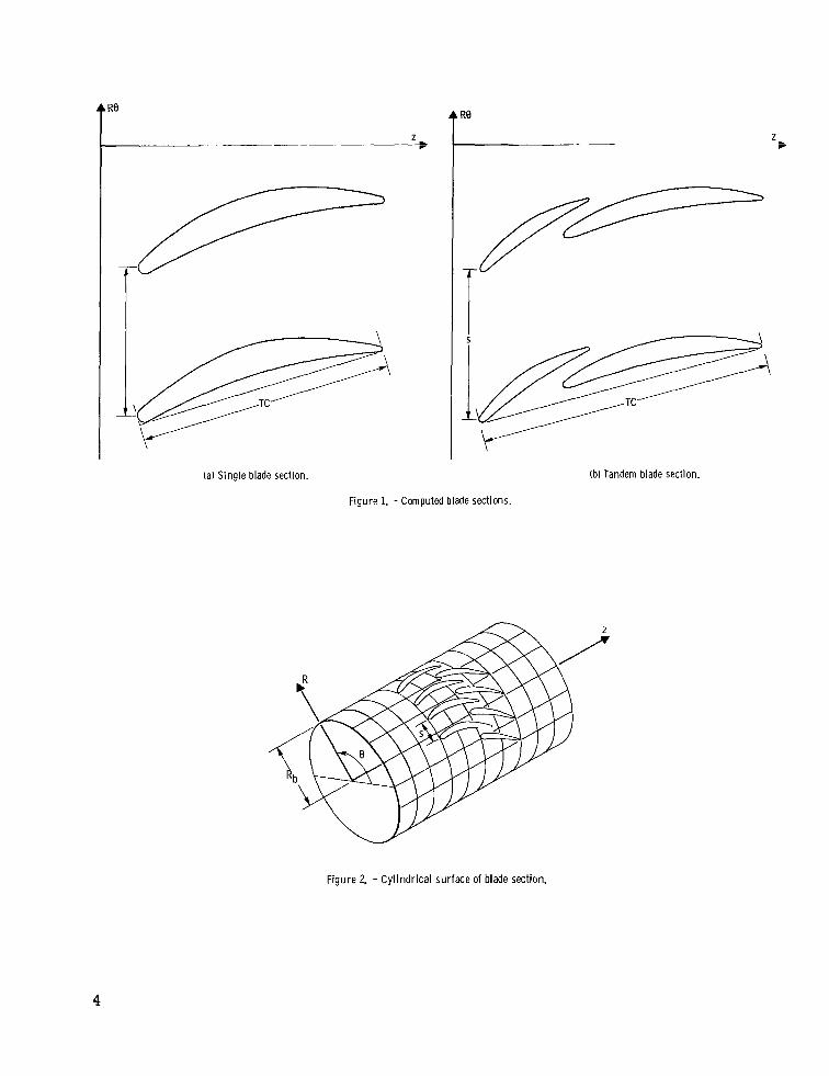
From given inputs, the program calculates and plots coordinates of either a single blade section (see fig. l(a)) or a tandem blade section (fig. l(b)) with up to five segments per blade. (The plane of fig. 1 is the unwrapped cylindrical surface of fig. 2. )
leading- and trailing-edge circles. The radii of these a r c s a r e a function of blade seg- ment cambers, chords, and thicknesses, which in turn a r e functions of given input pa- rameters. The position of the blade segments with respect t o each other is also a func- tion of the inputs.
All surfaces of the generated blade segments a r e single circular a r c s tangent to
3
R9
(a) Single blade section.
Figure 1. - Computed blade sections,
(b) Tandem blade section.
Figure 2. - Cy l indr ica l sur face of blade section.
4
\
F igure 3. - Input variables.
The input parameters (fig. 3) describe both the overall blade section and the individ- ual blade segments. The overall blade section is specified by a chord TC, camber AK, solidity cr = TC/S (see fig. l), inlet blade angle K ~ ~ , and radius from axis of rotation to cylindrical surface Rb (see fig. 2). of segment chord to the chord of the first blade segment C/C(l), ratios of segment cam- be r to f i r s t blade segment camber q/q( l), and ratios of maximum thickness and leading-edge and trailing-edge radii of the segment to local segment chord TM/C, RI/C, and RO/C. Segments a r e related to each other by the gap between them (in the form of ratio to total chord, G/TC), their overlap (also a ratio, L/TC), and the convergence in the channel between them F. (The chord, camber, gap, overlap, and convergence in- puts for the blade segments a r e not used when the blade section consists of only one seg- ment.)
cedure in order to properly s ize the segments in relation t o each other. camber AK and total chord TC and the segment camber ratios cp /cp ( 1) and chord ra- tios C/C(l), initial estimates of segment cambers cp and chords C a r e calculated. Circular a r c centerlines a r e fitted to these chords and cambers. The surfaces a r e also circular a r c s that a r e tangent t o leading- and trailing-edge circles, and meet the maxi- mum thickness requirement.
Individual blade segments a r e described by ratios
For a tandem blade (more than one segment), the program follows an iterative pro- From total
Finally, the segments are located with respect t o each
5
other. At this point the total camber formed from all estimated parameters is computed and checked against input total camber A K . Adjustments a r e made, and the entire pro- cedure repeated until convergence is reached on total camber. After convergence, blade section coordinates and other output parameters are computed, and a plot of the blade section is made.
Output from the program consists of printed computer listings and a Calcomp plot. The computer listings a r e divided into two main parts: (1) surface coordinates of indi- vidual blade segments suitable for making machine drawings and (2) geometrical input for blade-to-blade ideal flow programs (refs. 1 to 4) or a boundary layer program (ref. 5). The Calcomp plot shows the generated blade row a t the input blade angle. Two overall blades a r e plotted with the proper solidity in order to identify the flow passage.
The program is run a t NASA Lewis on the IBM 7094-7044 direct coupled system with a 32 767 word core (77777 ). The total program storage requirement is 65403 of which 31717 Ute per data set on IBM 7094 equipment.
(8) (8) is used in the storage of variables. The program runs in about 1/4 min-
(8)
Limi ta t ions of the Program
The following a r e the principal limitations of the program: (1) Blade sections a r e generated on a plane surface, rather than a conical or merid-
ional flow surface which would be more closely alined with the streamline flow when there is significant streamline slope.
(2) Blade segment surfaces a r e single circular arcs . Multiple circular a r c s or other types of variable geometry a r e not calculated by the program.
(3) Each set of input data generates only one blade section. provide radial stacking of blade sections after several sections have been run.
(4) The plotting portions of the program use routines that were developed at Lewis and would not be available or would need modification before they could be used on other machines. All other par ts of the program, however, a r e in FORTRAN IV code, and could be easily transferred to other IBM equipment.
The program does not
Use of Program
At Lewis, the program is being used to define blade sections for analytical para- metric studies using the programs of references 1 to 6. liminary screening of cascades formed by applying the input variables over a wide range.
The Calcomp plots allow pre-
6
Selected configurations are then examined analytically for ideal flow, boundary-layer development, and losses. Some of these sections a r e later selected for experimental study.
much across blade sections, output can be used for fabrication purposes. For applications in two-dimensional' cascades o r where radius does not change
N U MER ICAL EXAMPLES
Two numerical examples a r e given which illustrate the use of the program. The f i r s t is a two-segment tandem blade section, and the second is a three-segment blade section with the front section acting as a slat. same overall parameters which a r e listed in table I.
Both blade sections are designed for the The input for these two examples
T A B L E I. - O V E R A L L DESIGN P A R A M E T E R S
F O R TWO- AND T H R E E - S E G M E N T
TANDEM BLADE SECTIONS
1 .235 7 2 . 2 4 56. 53
Radius from axis or rotation,
Total chord, T C , f t Solidity, u Overall camber, A K , deg Inlet blade angle, K ~ ~ , deg
~~
and the generated plots of blade shapes appear in figures 4 and 5. These examples il- lustrate typical values of input parameters for two- and three-segment blade sections. Sample output for the first example is discussed under OUTPUT.
INPUT
Figure 6 shows the placement of input variables on data cards. The first input card is for a title which identifies the data set and is printed on the output. type whatever information he wishes in any of the first 72 columns of this card. remaining cards a r e for input data. The input variables a r e defined in the next section. Further explanation of the proper preparation of input is contained in the section Typical Values and Limits of Input Variables.
The user may The
7
Axial distance
E X A M P L E - T k C S E C T I C h ? A h C t M B L P O E
K A P l h R P C I U S 5 6 . 5 3 0 0.77080
TChCRI') S C L I O C E L h 2 0.18563 1 . 2 3 5 C 72.240
C / C I l J P K h P Y 1 . 2 5 c o o
F H I / P H I l I ) 9 K R A b
G / T C A 6 F A Y
L / T C P R P I Y
F ARRAY
1 M / C A R H P Y 0. I i C l C C
R I / C A R R P Y O . ( 1 5 C C
R O / C A R P A Y 0.00800
1 . 5 6 2 5 0
0 . 0 2 5 C O
0.10000
1 . 4 C C C O
0. LCCCO
0 . C i C C C
C . O C 7 0 0
Figure 4. - Input and generated plot of two-section tandem blade example.
E X d P F L E - T b R k E S E C T l C h TAhCEH 6 L A D t
f- v- Axial distance
N 2 SCL I D C E L K K P F I A RdCIUS T C H C k D
O . I E 5 E 3 1 . 2 3 5 C 72.240 56. 530 0.77080
C / C l 1 ) P R K D Y 5 . 1 C C O O
F H I / P H I 1 1 J A d R A Y 0 . 5 C O C O
G / T C A h H A Y C . C l 2 5 C
L / T C A R R A Y 0 . c 4 z c c
F P R R A Y I . 2 C C C O
l M / C A r l R d Y 0 . 1 4 C O O 0.12COO
R I / C A R R P Y O . O t C O 0 0 . C 3 2 0 0
R O / C A H F A Y 0 . 0 I L C C O.CC700
6 . C C C C O
C . 6 O C C O
C. 0 2 4 C t i
O . O S 7 C C
I . 4 C C C O
c . 1 z c c c
c. c 2 5 c c
0. C C 7 0 G
Figure 5. - Input and generated plot of three-section tandem blade example.
8
I I
Figure 6. - Input data form.
Input Variables
Schematic representations of these variables appear in figures 1 to 3. After the title card, the following input variables are given:
N integer number (1 to 5) of blade segments comprising the blade section; equals 1 when designing a single, circular-arc blade section; must occupy column 10 of the data card (fig. 6)
TCHORD total chord of the overall N-segment tandem blade section TC, f t ; m
SO LID solidity of the blade row, cr, that is, total chord divided by blade spacing
TC/S. a duplicate blade on the plot. )
(Solidity is only used in the plotting part of the program to produce
DELK total camber of the overall blade sections, AK, deg
KAPIN blade inlet angle or angle between tangent t o mean camber line at leading edge of f i rs t blade segment and the Z axis, K ~ ~ , deg
RADIUS radius from axis of rotation t o cylindrical blade plane F$,, ft; m (RADIUS is only used to convert tangential coordinates, RB, in feet o r meters, t o radians for input to the ideal flow programs, refs. 1 to 4.)
9
Each of the following a r r ays has N - 1 entries. Jf N = 1, a blank card should be given f o r each of these 5 a r rays .
COCl
PHOPHl
GOTC
LOTC
F
a r r ay of ra t ios of chords of blade segments 2 to N to the chord of the first segment, C/C( 1)
a r r ay of ratios of cambers of blade segments 2 to N to the camber of the first segment, cp/cp( 1)
array of ra t ios of gaps between blade segments to the total chord of the over- all blade section, G/TC
a r ray of ratios of overlap between blade segments to the total chord of the overall blade section, L/TC
array of channel convergences between blade segments, F (F is the ratio of the gap a t the channel inlet to the gap at the channel outlet. )
Each of the a r r ays below has N entries, one for each of the blade segments:
TMOC array of ratios of maximum blade segment thickness to chord of the individual blade segments, TM/C
RIOC a r ray of ratios of leading-edge radius to chord of the individual blade segments,
N / C
ROOC a r ray of ratios of trailing-edge radius to chord of the individual blade segments, RO/C
Typical Values and Limits of Input Variables
Ranges of typical values a r e given in this section for the input variables. Limits a r e also given beyond which unreasonable blade sections (and hence e r r o r s in the pro- gram) will occur.
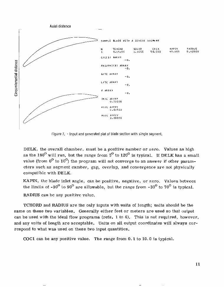
N, the number of blade sections, can be any integer from 1 to 5. For typical tandem blades, N is usually 2 o r 3. To design a single blade section, N is set equal to 1, and blank cards a r e used for the COC1, PHOPH1, GOTC, LOTC, and F arrays (Fig. 7 is the input and the corresponding output plot of a single blade section.) Since N is an integer, it must be right shifted on the data card; that is, it must occupy column 10 (see fig. 5).
TCHORD can be any positive value.
SOLID can also be any positive value; the range from 0. 5 to 2.0 is typical.
10
Axial distance
S A M P L E B L A D E W I l h A S I k G L E S E G M E N l
N TC HC K I I S O L I D C E L k K P P I N R A D I U S 1 0.kSiOC i.3occ 5o.ooo 45.000 0.0~500
C/C( 1 1 A d K P Y -0.
FH I / P H I ( 1 1 A R R A Y -0.
G / T C A R R A Y -0.
L/lC A R R P Y -0.
F ARRAY -0.
T M / C ARRAY 0.11000
R I / C A d R P Y 0.01500
P O / L P g R F Y 0 . 0 0 8 0 0
f i g u r e 7. - Inpu t and generated plot of blade section w i th single segment.
DELK, the overall chamber, must be a positive number o r zero. Values as high as the 180' will run, but the range from 5' to 120' is typical. If DELK has a small value (from 0' to 10') the program will not converge to an answer if other param- e te rs such as segment camber, gap, overlap, and convergence are not physically compatible with DE LK.
KAPIN, the blade inlet angle, can be positive, negative, o r zero. Values between the limits of -90' t o 90' are allowable, but the range from -30' to 70' is typical.
RADIUS can be any positive value.
TCHORD and RADIUS are the only inputs with units of length; units should be the Generally either feet o r meters are used s o that output same on these two variables.
can be used with the ideal flow programs (refs. 1 to 4). This is not required, however, and any units of length are acceptable. Units on all output coordinates will always cor- respond to what was used on these two input quantities.
COCl can be any positive value. The range from 0 . 1 to 10.0 is typical.
11
PHOPHl can be any positive o r negative value, or zero. Values f rom 0 to 3.0 are most common. To obtain a very straight front segment, PHOPHl should contain very large values. To obtain a very straight aft segment, PHOPH.1 should be near o r equal to zero for that segment.
GOTC can be any positive value f rom zero to about 0.5 depending on other inputs such as segment cambers, overlaps, and convergences. The range from 0.01 to 0.04 is typical.
LOTC can have positive or negative values, o r be zero. Typical values are con- tained in the range from 0.1 to -0.05. Values above 0.4 o r below - 0 . 2 will gener- ally cause e r r o r s and prevent the program from running.
F can have positive values from zero to about 10.0. The range from 0.9 (diverging passage) to 1 . 5 (converging passage) is most typical. When F = 1.0, the capture area of the passage between blade segments is equal to the exit area of the passage.
TMOC is allowed positive values from zero to about 0.8. Values in the range from 0.1 to 0 . 2 are most typical. Elements of TMOC must be at all times at least twice as large as the corresponding elements of RIOC and ROOC in order for the program to run. (If TMOC equals zero, RIOC and ROOC must also be zero for that blade segment. )
RIOC and ROOC may have positive values from zero to about 0.4. Most values are in the range 0.01 to 0 .1 . Corresponding elements of RIOC and ROOC do not have to equal each other. (RIOC may only equal zero if the corresponding element of ROOC also equals zero. ROOC, on the other hand, may equal zero at any t ime, regardless of the values in RIOC. )
Example of Adjustment of Inputs in Design Process
The program is used here to design a two-segment tandem blade section. Given the overall blade section parameters, an initial selection is made for the other input variables. These variables a r e subsequently changed (twice in this example) until a final blade section is accepted.
Changes a r e made after inspection of the machine plots which accompany the com- puter output. They a r e made to obtain a blade section which appears to have a good flow path while satisfying the overall blade parameters. These iterations on input variables a l so illustrate the effect of the different input parameters on the final blade shape.
The blade section to be designed has the overall blade parameters listed in table 11. In order to obtain an initial picture of a blade section meeting these specifications, gen-
12
TABLE TI. - OVERALL DESIGN
Ratio of gap to total
chord, G/TC
-
PARAMETERS FOR TWO-
Ratio of overlap to total chord, L/TC
SEGMENT TANDEM
BLADE SECTION
Totalchord, TC, ft 0.192 Solidity, u Overall camber, AK, deg
-
TABLE III. - VARIABLE INPUT PARAMETERS FOR TWO-SEGMENT TANDEM BLADE SECTION __ Ratio of seg- ment chord to chord of f i rs t
blade segment, C/C(1)
- ..
1.0
1. 3
_ _ - - -. ._ - -
Ratio of seg- ment chamber to f i rs t blade
segment chamber, 9/9(1)
.. - -
1 . 0
1. 6
- _ _
-__ -
0.05 I 0'1°
&ti0 of gap at channel inlet to gap at channel
outlet, F
1. 5
1. 1
1. 2
b t i o of maxi- num thickness to local seg- ment chord,
TM/C
. .
0. 15 . 15
0. 13 . 13
0 . 1 1 . 12
b t i o of leading- edge radius to local segment
chord, RI/C
0.02 .02
_ _ _ -
_---
- - - - _---
Ratio of trailing- edge radius to local segment
chord, RO/C
0 . 0 1 .Ol
0.007 .007
- - -__ _ _ _ _ _
era1 initial values of the other input parameters were chosen and run. These values a r e listed in table I11 (run 1).
experience and his concept of the final desired blade shape. For this example we wanted more chord and camber to be concentrated in the r e a r blade segment; so , in run 2, C/C(l) was increased from 1.0 to 1.3, and q/q (1) f rom 1.0 to 1.6. The channel gap w a s a lso decreased (G/TC = 0.05 to 0.03), as well as the channel convergence between blade segments (F = 1. 5 to 1.1) in order to bring the segments closer together. Finally the blade thicknesses TM/C and the outlet radii RO/C were reduced. The blade sec- tion resulting from run 2 (table 111) is pictured in figure 8(b). From experience it ap- peared that this blade section w a s still thicker than desired and that its channel needed more convergence. Appropriate changes were made for run 3 (table Ill), and the final blade section is shown in figure 8(c). the ideal flow programs (refs. 1 to 4).
The resulting blade section is shown in figure 8(a). Changes made after an initial run on the program a r e entirely based on the user 's
This section w a s accepted for further analysis by
13
Axial distance r--- -- ~~ - ~ -~ ~ r ~ - - -
(a) R u n 1. (b) R u n 2.
Figure 8. - Blade plots for subsequent design r u n s of two-segment tandem blade section,
(c) Run 3.
OUTPUT
Output from the program consists of two principal parts: a computer listing with printed tables of output variables and a Calcomp plot that pictures schematically the generated blade.
A sample computer listing for the two-section tandem blade example is given in table Tv. In this table some sections of the output have been abbreviated because they were too long. In all cases output labels agree with program variable names which are defined in the next section.
TABLE IV. - SAMPLE OUTPUT FOR TWO-SECTION TANDEM BLADE EXAMPLE
EXAMPLE - T W O S E C I I O N TANOEH eLbDE
N TCHORO SOL10 OELL K A F l N R P D l U S 2 o . I E : ~ ~ 1.2350 7 2 . 2 4 0 56.530 0.77080
C/Cl 1 1 l R R A Y 1.25CCC
G/lC A!lHPY C.CL5CC
L / l C P C F d Y ( . ICCCO
f LHRAY I.4CCCC
l H / L AHllAY c . i i o o o a.ioaao
c.ai5cc o.ozooa n L / L A N P b Y
RO/L AHPAY C.00800 0.00100
LbtCLLL JLACt PAHACtltHS N TLHUND P I 1LH 5CLlC C€LK m b P I N G b M B 1 h F l a xns Yel l
C . l E 5 f . 3 C.15047 1.2353 72.240 >6.5100 I ^ l . t . l S t C.IPL') 9.17413 - . C h > I ' 2
CHUHC i . c 5 : f 4
X I c.co14c
X l c .
Fhl $ 5t .5i34?
FHIL 5 4 . ? J e t 1
P H I P 1 2 .i4C54
X X C.
C.CC4LC c . s o t c o c .cotcc (.CICLC C.CliCC c.ClrCC
C.01293 c . o i i i 5 C.Cl333 0.01347 0.01357 C.01362 C.01364 C.01361 0. c1354 C.01343 C.01328 0.01309 C.Cl286 C.Cl258 0.C1226 C.Cl190 C.Cl150 C.01105 0.01055 c.c1ocz 0.00543 C.CO880 c. CC812 c.cc739 0.00662 c . cc5 79 c.cc49c C. C0397 C.CO257 C . 00192
Cl-QRO R 1 R O THETA C. l lbC7 C.OC233 O.COC82 0.76547
X I ri xo vc xcn Y cn a .oo i?3 c.cc233 0.11586 o.00082 0.05386 0.01522
a i V I x2 12 c-PC GAMR C.C7C86 C.CO825 C. 17448 0.06189 27.36919 27.36919
P P I 5 R S HS R S Y I S KOS 7C.04290 C. 10C49 0. C5669 0.07939 33.62912 36.41378
PHI!- RC HC RE U I C KO C 54.23rrC C.12454 0.C5761 0.10927 26.35063 27.88157
F h I P R P H P B P Y I P KO P 37.E-5516 0.17337 0. E5922 0.16391 18.89117 18.97399
G G I G l O C 1 F Fb SINC C.00465 C.00463 0.04960 0.01858 1.40000 1.40619 -9.55789
X X v s VP hOEL = 2 4 0 . C.00357 -C.O0096 C . O O 4 C O C.CO676 C.COC77 C.01000 C.CO555 O.CO233 C . O l S C 0 0.01204 O.CO373 .... . .. -~ C.C20CO C.01416 0.004S7 CSC24CO 0.01597 0.00605 0.C3COO ( -01748 0.00698 0.03:oo c .c ie7z 0.00176
C O M P L I E O I N P U T FOR IDEAL FLOW PROGRIWS
RLAM MCHORD S T G R R S T G R R 1 RO WL E THLE RTHLE n TF THTE RTHTF 1 0.C7284 0.C7474 0.05761 0.00140 0.00075 0. o.ocooo o.ooooo 0.07284 0.07474 0.05761 2 O i l 1 4 4 2 0.02924 0-02254 0.00233 0.00082 0.06054 0.C5137 0.03960 0.17496 0.08062 0.0h214
e L m B E T I S B E i o s B E T I P e E T w 1 67.07586 10.55239 45.70413 33.46359 2 45.84613 -24.15677 31.10818 -6.75690
UCL TCCL RTHCL nc T T H C T R T H C T 0.00140 0.00000 C.00000 0.07209 0.07474. 0 .05761 0.06287 0.05137 0.03960 0.17415 0.08062 0.06214
16
TABLE W . - Concluded. SAMPLE OUTPUT FOR TWO-SECTION TANDEM BLADE EXAMPLE
B L A C E I E b M E h I N O . I
H S P S I H S P S -(.CCC22 - c . o o c 3 1
(. l ,CC66 J.OCZ37 C.LCI5E C.CC5CC c.UC254 C.CC158 ( .OCi53 C.OIC1C c . c c 4 5 5 C.CI25C (.OC561 C.0149E ( e C C t 6 9 0 .01735 (. l>C78l C.CI96t C.CCCS6 C.02193 ( . 0 1 0 1 4 C.C2416 C.01134 C.C2634 C.01258 C.02847 C.O1?84 C.C3056 ( . O I L 1 4 C.Cj26C C.Olt4t 0.C346C c . o i i e c 0.C3656 (.OISIE c . c 3 8 4 e c . n i c 5 ~ c .c4c35 C - O i i L C C.C4219 l.Oii46 0 . c 4 3 9 e ( - O r 4 5 4 C.C4513 C . J i t 4 4 C.C4744 C.02198 c . c 4 4 1 c ( . O i 5 5 3 C.C5OlJ C.03112 C.05232 ( . l l ! i 7 2 C.C538t ( . 0 3 4 9 7 C.C553t ( . U I f C 3 0.C5683 ( . C : i I L C.C5825 C.33C44 C.CS562 (.J411e C.CbC96
C . 3 4 4 1 5 C.C635C i . n G i y 5 c . c t 2 2 5
C . J G t 5 6 C.Cb471 ( . n L t G j c . c c 5 ~ i ( . i i f C j 2 C.C6bSB ( . C ~ L L ! C.CbrJC5 C . 1 1 5 4 1 t C.CbSC7 ( . s J L C 1 5 C.C7LC5 ( .'I I t 1 t c . c 7 c 9 1 ( . C t ( 1 5 C.C7185 ( . C t i i t J .C72t7 ( . C t < ? 7 C.Cl344 ( . ( f t L C C.C7416 ( . t t E 6 6 C.C7+02 ( . C 1 ( 8 5 C.C7542
I H S P S c . c c c s 3 C-CC637 C.ClI 3 c C .Cl57r C.CiS84 C . C L 1 5 1 C.CZO8I
RTHSFS -C.CCC24
C.CCl83 O . C C 3 E t O.CC584 C.CC178 C.CC5bE 0.C1155 C . ( 1 3 3 1 C - C I 5 1 6 0 .01691 0 .01862 c. c 2 0 3 c C . C2194 C.C2355 0 .C2513 C.02667
0 .C29t6 C.C3ILC 0.C3L52 c . c 3 3 5 c C.03525 C.03656 C.03185 L . ( 3 9 1 t C. C4033 0.C4152 0. C4LoE 0.C438L C . c 4 4 9 c C.C4596 U.C469S C . C4798 C.C4895 0 .04S87 C.05017 0 .C5163 C.C5245 0 .C5324 c . c 5 3 9 5 c .05471 C.C553E C . C56C2 C.C5661 0.C5116 C-C5767 0.C5814
0.C11SS O.Cl33C 0 .01412 0 .Cl tCE 0 . C 1 7 4 i O.ClE7C 0 .c201c 0.02142 0 .02274 O.?24C5 r).C253C O . O Z t C 5 0. (?2754
0.C3C45 0 .C311t
0 .03427
3 . 0 3 t 7 t 0 .03755 0 . C 3 9 i l C.O4C4? 0 .C41t4 0.042E4 0.C44C4 0 .C4 522 0 .C4trC 0.041 5 E 0.C4E74
n . c z s i 2
0 . 0 3 9 ~ 2
c . n 3 5 c i
0 . 0 4 9 s ~ 1 . c 5 1 c : 0.C52iC 0 .05333 0 .0544 t 0.C555C O.CSt7C
P S P P 0 .OO 0 15 0 .00527 0 . 0 0 9 8 3 0 . 0 1 4 4 2
r b s w R T ~ S P P - 0 . 0 0 4 8 ~ -n.on312 -0 . o n I 25 -c . n c c 5 7
n .00210 o . c c 1 t z 0.00525 0 . ~ 0 4 ~ 4
0 . ~ 1 1 0 4 0 . 0 0 8 1 9 o.ont?i 0 . 0 2 3 1 5 0 .01094 0 . ~ ~ 8 4 3 0.07d35 0.01349 O . C I C 4 C
Output Va ria bles
The first page of output contains a copy of the input to the program.
The next page of output lists some overall blade section parameters, some of which
These variables a r e defined in the Input Variables section on page 9.
a r e repetitions from the input list. The others a r e defined as follows:
PITCH
GAMB
blade-to-blade spacing S in the 8 direction or ratio of total chord to solidity TC/D (fig. l), f t ; m
angle between chord line of f i r s t blade segment and chord line of overall blade section (fig. 9), deg
17
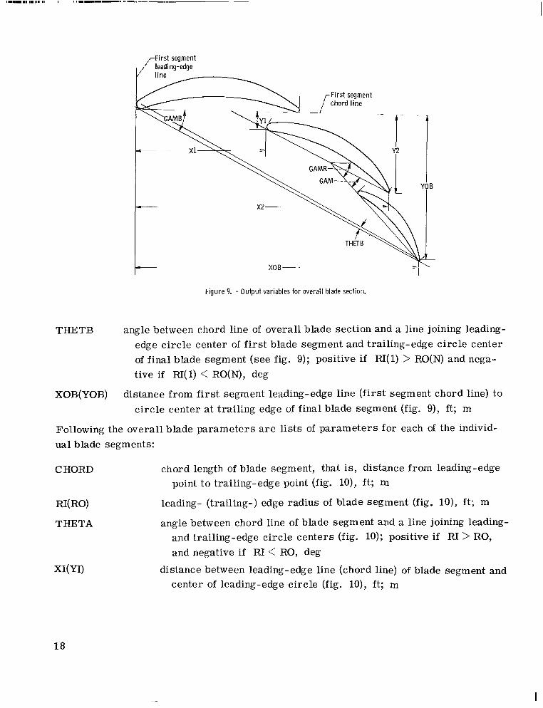
1 XOB- -
F igu re 9. - Output variables for overal l blade section.
THETB angle between chord line of overall blade section and a line joining leading- edge circle center of f i r s t blade segment and trailing-edge circle center of final blade segment (see fig. 9); positive if FU( 1) > RO(N) and nega- tive if RI( 1) < RO(N), deg
XOB(Y0B) distance from first segment leading-edge line (first segment chord line) to circle center at trailing edge of final blade segment (fig. 9), ft; m
Following the overall blade parameters a r e lists of parameters for each of the individ- ual blade segments:
CHORD chord length of blade segment, that is, distance from leading-edge point to trailing-edge point (fig. lo), f t ; m
RI( RO) leading- (trailing-) edge radius of blade segment (fig. lo ) , f t ; m
angle between chord line of blade segment and a line joining leading- and trailing-edge circle centers (fig. 10); positive i f RI > RO, and negative i f R1 < RO, deg
distance between leading-edge line (chord line) of blade segment and center of leading-edge circle (fig. lo), ft; m
18
I
I
XO(Y0)
XCM(YC M)
x 1(Y 1)
X2(Y2)
GAM
GAMR
PHIC(PHIS, PHIP)
RC(RS, RP)
HC(HS, HP)
BC(BS, BP)
Figure 10. - Output variables for ind iv idual blade segment
distance between leading-edge line (chord line) of blade segment and center of trailing-edge circle (see fig. lo), ft; m
distance between leading-edge line (chord line) of blade segment and point on mean camber line at which slopes of both blade sur- faces a r e equal to slope of mean camber line (fig. lo), ft; m
distance between leading-edge line (chord line) of f i rs t segment and leading-edge point of local segment (fig. 9), ft; m
distance between leading-edge line (chord line) of f i rs t segment and trailing-edge point of local segment (fig. 9), f t ; m
angle between chord line of local blade segment and chord line of previous blade segment (fig. 9), deg
angle between chord line of local blade segment and chord line of f i rs t blade segment (fig. 9), deg
overall camber of local blade segment mean camber line (suction surface, p ressure surface) f rom a line through leading-edge circle center to a line through trailing-edge circle center (fig. 1w>, deg
tion surface, pressure surface) (fig. ll(a)), ft ; m radius of curvature of local blade segment mean camber line (SUC
distance from leading-edge line of blade segment to center of cur- vature of mean camber line (suction surface, pressure surface) of blade segment (fig. ll(a)), ft ; m
distance from chord line of blade segment to center of curvature of mean camber line (suction surface, pressure surface) of blade segment (fig. ll(a)); negative when PHIC(PHIS, PHIP) is negative
19
(a) Ent i re blade segment (b) Enlarged leading edge.
Figure 11. -Con t inua t ion of ou tpu t variables fo r indiv idual blade segment.
When PHOPH1, and thus PHIC, of a segment equals 0, RC and BC a r e se t to 999.99999.
KIC(K0C) angle between chord line of blade segment and tangent to mean camber line a t the center of leading-edge (trailing-edge) c i rc le (see fig. ll), deg
KIS(K0S) angle between chord line of blade segment and tangent to suction surface at leading-edge (trailing-edge) transition point (see fig. ll), deg
KIP(K0P) angle between chord line of blade segment and tangent t o pressure surface a t leading-edge (trailing-edge) transition point (see fig. ll), deg
KIC(KIS, KIP) and KOC(KOS, KOP) a r e defined positive as shown in figure 11 for a They w i l l be negative for a surface centerline or surface which has positive camber.
with negative camber.
20
G gap between trailing edge of previous blade segment and suction surface of local blade segment (fig. 12); measured perpendicular to the chord line of previous blade segment along line passing through trailing-edge circle center of the previous blade segment, ft ; m
GA actual gap between trailing edge of previous blade segment and suction surface of local blade segment (fig. 12); measured perpendicular to suction surface of local blade segment along line passing through trailing-edge circle center of previous blade segment, ft; m
GAOC
L
ratio of GA to CHORD of previous blade segment (fig. 12)
distance between gap G at trailing edge of previous blade segment and gap (FXG) at leading edge of local blade segment (fig. 12), f t ; m
F ratio of gap FxG at leading edge of local blade segment to gap G at trailing edge of previous blade segment (fig. 12) FXG is measured perpendicular to chord line of previous blade segment along a line passing through leading edge circle center of local blade segment
FA ratio of actual gap FAXGA at leading edge of local blade segment to actual gap GA a t trailing edge of previous blade segment (fig. 12) (Actual gap FAXGA is measured perpendicular to a line (A-A in fig. 12) which bisects the tan- gents to the suction surface of the local blade segment and the pressure sur- face of the previous blade segment where the line FAXGA meets these sur- faces. center of the local blade segment.)
The line containing FAxGA passes through the leading-edge circle
Figure 1'2. - Input and output variables in overlap region.
21
SINC
xx
YS(YP)
NDEL
angle between tangents to mean camber lines of local blade segment and pre- vious blade segment at points of intersection with line containing D<G (see fig. 12), deg (SINC is a measure of the incidence of the average blade-to- blade flow on the leading edge of the local blade segment. SINC is negative as shown in figure 12 since the mean flow would have negative incidence in this blade orientation. )
a r ray of distances (parallel to blade segment chord line) between leading-edge line of blade segment and points a t which blade surface coordinates (YS and YP) are given (fig. lo), ft; m
a r r ay of perpendicular distances from chord line of blade segment t o points on suction (pressure) surface of the segment (fig. lo), f t ; m
number of blade coordinate points (XX and YS, XX and YP) along suction o r pressure surfaces of local blade segment.
For blades with normal levels of positive camber, some values of YP at inlet and outlet may be negative. These a r e points on the pressure or suction surface circular a r c s that occur prior to the leading-edge radius or after the trailing-edge radius (fig. 13).
----I xx CHORD t-------
Figure 13. - Blade surface coordinate points.
For a blade with small positive camber, or with negative camber, many values of YP (and sometimes YS) can be negative (fig. 14).
Following the blade coordinates for each of the blade segments a r e output param- e te rs that serve as inputs for the ideal flow programs. These programs are reported in references 1 to 4. They compute ideal flow on an axisymmetric blade-to-blade sur- face of a single or tandem bladed turbomachine in either subsonic or mildly transonic flow.
To obtain input to be used in the ideal flow programs, the flat plane in which the blade section l ies is assumed to be wrapped about a cylinder of radius equal to the input parameter, (RADIUS, %, in fig. 2). This cylinder se rves as the axisymmetric blade- to-blade surface required for the input of geometry t o the ideal flow programs.
22
- (a) Small positive or negative camber.
\ (b) Negative camber.
Figure 14. - Example blade sections with negative surface coordinate points.
Specific output quantities which a r e required as geometric input parameters in the ideal flow programs a r e defined in the following:
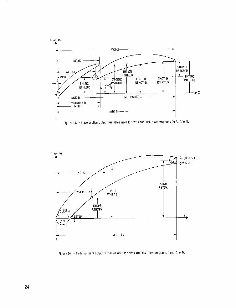
MCHORD
ST GR
RSTGR
RI(R0)
MLE( MTE)
T HLE( THTE)
RTHLE ( RT HTE)
BETIS( BETOS)
chord lengths of blade segments in Z direction (figs. 15 and 16), ft; m
angular 0 coordinates of trailing edges of blade segments with re- spect to leading edges of blade segments (figs. 15 and 16), rad
angular distances of trailing edges of blade segments from leading edges of blade segments (figs. 15 and 16), ft; m
leading-edge (trailing-edge) radii of the blade segments (figs. 10 and IS), f t ; m
distances in Z-direction from leading edge of first blade segment to leading (trailing) edgPs of other blade segments (fig. 15), f t ; m
angular 0 coordinates of leading (trailing) edges of blade segments with respect to leading edge of first blade segment (fig. 15), rad
angular distances of leading (trailing) edges of blade segments with respect t o leading edge of first blade segment (fig. 15), ft ; m
angles with respect to Z-direction a t tangent points of leading- (trailing) edge radii with suction surfaces of blade segments (fig. 16), deg
23
MLE(2 MCHORD(2)- ~
[?T;;RG!q MTE(2)- -
Figure 15. - Blade section output variables used fo r plots and ideal f low programs (refs. 1 to 4).
9 or Re
MC HOR D-
Figure 16. - Blade segment output variables used for plots and ideal flow programs (refs. 1 to 4).
24
BETIP( BETOP)
MC L( MCT)
THCL(THCT)
RTHC L(RTHCT)
angles with respect to Z-direction at tangent points of leading- (trail- ing) edge radii with pressure surfaces of blade segments (fig. IS), deg
distance in Z-direction from leading edge of f i r s t blade segment t o centers of leading-edge (trailing-edge) c i rc les of blade segments (fig. 15), f t ; m
angular 6 coordinates of centers of leading-edge (trailing- edge) cir- cles with respect to leading edge of first blade segment (fig. 15), rad
angular distances of centers of leading- edge (trailing- edge) c i rc les with respect to leading edge of first blade segment (fig. 15), ft; m
The preceding variables are followed by the coordinates of suction and pressure sur- faces of the individual blade segments. These coordinates are given with respect to axes in the Z-direction passing through the leading-edge circle centers of each of the seg- ments.
M SPS( MSPP) array of distances in Z-direction between leading edges of individ- ual blade segments and points on the suction (pressure) surface at which blade coordinates (THSPS and THSPP) a r e given as out- put (fig. IS), ft; m
THSPS(THSPP) a r r a y of angular 0 coordinates from a line in the Z direction through the leading edge circle center of each segment, to points on the suction (pressure) surface of the segment (fig. 16), rad
RTHSPS(RTHSPP) array of distances (RADIUS X THSPS(THSPP)) corresponding to THSPS(THSPP) (fig. IS), ft; m
Output Blade Plots
The Calcomp plot portion of the output shows the blade as it would appear in cascade a t a given solidity and inlet blade angle. The plot is very helpful in evaluating the blade visually; the user can see immediately whether the shape resulting from the program agrees with his concept.
The complete Calcomp plot for the two-section tandem blade example is shown in figure 17. All plots have the same format as this one. To the left of the plot a r e printed the complete input and some selected output variables. The input variables on the Cal- comp plot and in the program are related as follows: C/C(1) = COC1, PHI/PHI(l) = PHOPH1, etc. For the output, PHI a r e the blade segment cambers, PHIC. The blades
25
PJTCY KRF!I\I $93 ! U5 . .5@45 55.~110C ,77059
I +..-- : a- %?c ... . c: c: r c .I4 .II . 1 3 15 .I7 .I9 .21 .23 25 '<I-..-+-. +-- -e-- :
Figure 17. -Full Calcomp plot for two-section tandem blade example.
a r e drawn in a position corresponding to the blade angle, KAPIN. mal to the sides of the Calcomp page. The blade is not positioned at (0,O) and its origin has no set position in relation the plotted axis. amination of the blade.
for the NASA Lewis system and would not work elsewhere. However, the program is written with the plotting code at the end. A programmer at another installation could easily substitute a code to obtain a plot based on the requirements of his own system.
(See COMPLETE PROGRAM LISTING.) Down to statement 310 of this routine the blade coordinates have been stored into two arrays: XDOWN and YACROS. points on each blade segment have been stored into the a r ray , NPNTS. After statement 310, the section of code labelled PREPARE KKK AND P AND CALL CALPLT prepares special variables for a call on the CALPLT routine which is internal to the Lewis sys- tem. The subroutine CALTIT, which wri tes the input and output to the left of the plot, a lso uses special Lewis routines. Finally, the statement DECK CALPLT calls in the CALPLT routine which does the plotting. So from statement 310 of the PLOTT routine t o the end of the coding, changes would have to be made by a programmer to get plotting on another system.
The Z-axis is nor-
So the plot is only useful for visual ex-
The portion of the program which generates the Calcomp plot is coded specifically
The coordinates for plotting are calculated and arranged in the PLOTT subroutine.
The number of
Error Conditions
Several e r r o r messages a r e given by the program under certain conditions.
(1) MAX THICKNESS OF SOME SEGMENT IS LESS THAN LEADING OR TRAILING
This section l is ts the e r r o r messages and explains what to do if they a r e encountered.
EDGE THICKNESS O F THAT SEGMENT
This message is printed i f ei ther of the following conditions is found on any of the blade segments
TMOC < 2.0 X RIOC
The blade segments must be at least as thick as their leading- or trailing-edge thick- nesses.
(2) THE SUM O F ONE PLUS THE VALUES IN THE PHOPHl ARRAY MUST BE GREATER THAN 0 . 1
27
This message is only printed when negative input values are used in PHOPHl and the sum of these input values is less than -0.9. When excessive negative cambers are used, the program cannot converge on its iterations to calculate individual blade segment cam- bers. (A negative input to PHOPHl implies that the first blade segment will have posi- tive camber, and the segment corresponding t o the negative PHOPHl will have negative camber. So the e r r o r message eliminates long iterations on bad data. )
This situation is permitted in the program, but is physically unrealistic.
(3) PROCEDURE FOR SIZING OF BLADE CAMBERS HAS NOT CONVERGED IN 25 ITERATIONS
The program initially calculates blade segment cambers and then cor rec ts these cambers in an iteration process until an overall blade camber of DELK is obtained. Usually four o r five iterations are required to reach a specified tolerance. The e r ro r message is given i f convergence is not obtained in 25 iterations. This e r r o r is generally due to the fact that specified inputs a r e not geometrically compatible. This condition is most likely to occur when DELK is small (0' to 10').
root of negative number) a r e likely to occur if input values a r e beyond recommended limits. Limits within which computer e r r o r s are not likely a r e summarized.
In addition to the programmed e r r o r messages, computer e r r o r s (such as square
TCHORD > 0.
SOLID > 0.
0. 5 DELK 5 180.
-90. 5 KAPIN 5 90.
RADIUS > 0.
COCl > 0.
-1000. 5 PHOPHl 5 1000.
0. I GOTC 5 0 .5
28
-0.2 5 LOTC I 0.4
0.. 5 F I 10.
0. 5 TMOC I 0.8
0. 5 Fuoc I O . 4
0. I R O W I 0.4
COMPLETE PROGRAM LISTING
S I E J O E S X E F T C CATbP
S I E F l C BLCCR
1 2
4 5 6 7 E 5
1c 11 1 2 1 3 14 1 5 I C 17 18 1 5 ? C 2 1 22
2 -
29
C c C
C G C
C G C
CELK = D E L K / 5 7 . 2 S 5 7 7 9 P I T C H = lCHOKD/SOLID
SUML= 0. SLMPHI= 0. P P O P h l ( I ) = 1.0 I F (N.EQ. 1 1 GO TO 30 0 0 2 0 J = 2 r N
SUMC= 0 .
SUML= SUML+COSC(J) SUMC= SUMC+COCl (J )
2C SUMPHI= S U M P H I + P H O P H l ( J ) 3 C FACTOR. l . l ( 1 . -GkLK**2/24. I
SUML= F A Z TOK+SLWL
SUMPHI= l.+SUrYPHI I F ISUMPHI.GT.. l) GO T O 4 C WK I T € ( 6 , l i 7 c GO TO IC
P h I C ( 1 ) = GELK/SbMPHI I F {N.EQ. l ) G C 10 6 0
P H I C ( J 1 = P H I L ( l ) * P H U P H l ( J )
SUMC= 1.+ SUMC
4C C l - G R D ( I ) = TCHORD*SUML/SLPC
DO 50 J = L , N
5C C H O R D ( J ) = C H U R G ( l ) * C O C l ( J )
S I Z I N G O F CTI-ER B L A O E SEGCENT D I C E h S I C h S
39 4 c 41 42 43 44 45 46 47 48 44 5 c 5 1 5 2 53 54 5 5 56 57 5 6 55 t C 6 1 6 2 6 3 64 t 5 6 6 t7 68 e 5
3 6
?a
30
L ( J ) = L @ T C ( J ) * l C H O R D 7C G ( J )= G O T C ( J ) * l C H O R D 8C DO 5 0 J = l , N
T M ( J ) = T M U C ( J ) * C H O R D ( J ) R I ( J 1 = R I C C ( J J*CHGRD ( J I R O ( J J = R O O C ( J I * C H O R D I J ) I F N R I T E ( 69 1 1 2 0 )
( 2 .*R I ( J 1 Lk TM( J I .AND.Z-*HO( JI LE. JM( J 1 1 G C TO 90
GO TO IC 4C C O N T I N C E
C C S E G M E N T C f i h T E R L I h E C A L C U L A T I C N S G
GO 100 J = l v N X I ( J ) = K I ( J I Y I ( J ) = R I ( J ) X U ( J ) = C b O R D ( J ) - R C ( J I Y O ( J 1 = R O ( J ) ARG=( Y I ( J ) - Y O ( J I 1 / ( X I ( J I - X C ( J I I
I C C T H E l A ( J ) = - A T A K ; ( A R G I I 1 C DO 1 3 0 JZ1.N
K I C ( J 1 = P H I C ( J ) / 2 - - T H E T A ( J ) K O C ( J I = - P H I C ( J I / Z - - T H E l A ( J ) I F ( A d S ( P h I C ( J J ) . L T . . O O C l ) G C TO 120 B C ( J ) =
H C ( J ) = - X I ( J I - ( Y I ( J l + B C ( J I I * T A b ! ( K I C ( J I ) K C ( J ) = S O R T ( ( X I ( J l + H C ( J ) ) * * 2 + ( Y I ( J I + E C ( J ) 1462) GO TO 1 3 0
( X I ( J )** 2+ Y I ( J 1 * * Z - X O ( J) + * 2 - Y 0 L J 1 t4'2-2. * ( X I ( J ) -X O( J 1 1 *( X I 11 J ) i Y I ( J ) * T A N ( K I C ( J ) ) 1 I /Z. / ( Y O ( J ) - Y I ( J ) + ( X I ( J ) - X O ( J 1 I *TAN( K I C ( J ) ) I
12C B C ( J ) = 999.95999 IF ( P k I C ( J j - L T . C * l B C ( J ) = - B C ( J ) HC( J ) = - C h O R D ( J 1 /2. R C ( J ) = 9Y9.59959
13 C C O N T I K C E C C SEGMENT S l R F P C E C A L C L L A T I O N S C
00 2 7 C J = l , N K l = 0 I T l R = 0 CEL = O.l*CHORD(J) I F (KI(J1.EQ.O.) G O T O 140 R O K I = K O ( J ) / K I ( J ) - l . GO TO 150
1 4 C R O R I = 0. 1 5 C R O M R I = R O ( J ) - R I ( J )
CRO = C H O R O ( J ) - 2 . * K O ( J ) C V = ( 1 C ( J )-2.*RI ( J ) 1 / C H O R D ( J )
X C M M l = X C M ( J ) X C M ( J I = C H D R D ( J ) / Z .
L C = P C = P H f C ( J ) /2 .0 HCM=
S C P T ( ( C H O R C ( J I - R I ( J ) - R C ( J ) )**Z+ ( R I ( J ) - R C ( J ) ) * * 2 )/2,0
L C* T A N ( P C / 2 0 1 X C = R 1 ( J b i L C * C G S ( T H k T A ( J ) ) + H C P * S I F ; ( T H E T A ( J) 1
1 t C YCM ( J = R O ( J 1+ ( R I ( J 1-RO ( J ) *( C H C R D ( J 1 -XCM ( J ) - R a t J ) / ( C K I R D ( J l - R I ( J ) - R O ( J ) )
I F ( A @ S ( P H l C ( J J I .LT. .OCOl) GC TC 170 A L P H= Y CM ( J ) = Y CM ( J J +LC /C US ( T H k TA ( J ) I * (SI N ( PC / ( 1 . + C O S ( PC 1 1 -S I N ( AL PHI **2
ARG=
IHE 1 A ( J 1 + A S I N ( ( XC-XCM ( J ) ) / LC* S I h ( PC J - S I N ( T H E T A ( J ) 1
1 / ( ( l . + C O S ( A L P h I ) * Z I N ( P C ) 1 )
1s I N ( P C ) i L C * C O S ( K I C ( J 1 1 1 17C - ( ( XCM( J ) - R I ( J 1 ) * S I N ( P C ) - L C * S I h ( K I C ( J) 1 1 / ( ( Y C M ( J I - R I ( J ) *
7 c 7 1 7 2 7 3 74 75 7 e 7 7 18 75 8C 8 1 8 2 e3 84 e 5
C F I N A L C A L C U L A I I O N S AFTER COKbERGEhCE i 6 C R S ( J ) = S 4 ~ T ( ( X S H ( J ) + H S ( J ) ) * * 2 + ( Y S M ( J ) + B S o ) t * 2 )
R P ( J ) = SQRT((XPM(J)+HP(J))**2+(YPM(J)+BP(J))**2) ARG = - ( K I ( J ) + H S ( J ) ) / ( R I ( J ) + B s ( J ) ) K I S ( J ) = A T A N ( A R G 1 ARG = - ( K I ( J ) + ~ P ( J ) ) / I R I ( J ) + B F ( J ) ) K I P t J ) = A T A N t A R G ) ARC K O S l J ) = A T A N t A R G ) PRG K U P ( J ) = A T A N f A R G ) P H I S t J 1 = K I S ( J ) - K O S ( J )
i7C P H I P ( J J = K I P ( J ) - K O P ( J )
= - (CHORD( J ) + H S ( J 1-RO ( J ) 1 / ( R O ( J ) + e S( J ) 1
C C L C C A T I O N C.F ELADE SEGKENTS k I T H RESFECT T C ChE AhCTFER C
G A H ( 1 1 = 0, GAMR( 1 ) = 0. I F ( N . € Q . I ) GG TO 33C DO 3 1 0 J = 2 r N X R ( J I = C H O R D ( J - l ) - R O ( J - l ) - L ( J )
Y R ( J ) = S Q R T ( K P ( J - l ) * * 2 - ( X R ( J ) + H P O ) * * 2 ) - ~ P ( J - l ) - F ( J ) * G ( J ) - R I ( J ) GO TU 290 YR( J ) = - C i l R T ( RP (J- 1) **2- t X R ( J ) +HP ( J - 1 1 1 * * 2 ) -BP ( J - 1 ) - F ( J 1 *C( J
Y G ( J ) = - G ( J ) A A = 2 . * ( ( XG( J I - X H ( J ) ) * ( R I ( J ) + H S ( J) ) + ( Y G ( J ) - Y R ( J ) )*(GI( J ) + B S f J ) B B = 2.*t ( X G ( J ) -XR( J 1 ) * ( R I ( J ) + B S ( J ) I - ( Y G ( J I - Y K ( J ) ) * ( R I ( J)+HS( J ) 1 ) CC= R I ( J ) * ( i.O*R S ( J ) -K I ( J t ) - I XG ( J 1 - X R ( J ) 1 * * Z - ( Y C ( J ) - Y H ( J 1 ) * * 2 I F ( L ( J ) . L T . O . ) GO TO 300 SINCPM = ( B B * C C - A A * S Q R T ( A A * * Z + B B s o 2 - C C + * 2 ) 1 / ( P P p 4 2 + ~ @ * * 2 ) GO TU 310
3 0 C SINGAM = (Bd*CC+AA*SQRT ( A A * * 2 + B E * * 2 - C C * * 2 ) I / ( P A * * 2 + E E * * 2 ) 3 1 C G A M ( J ) = A R S I N ( S I N G A M 1
I F ( B P ( J - l ) . L l . . U ) GU TO 2 8 0
2 8 C 290 X G ( J 1 = CHORD( J- 1 )-KO ( J-1)
- R I ( J
C C CHECK CN OVERALL ELADE T l i R h I h G Ah0 F E S I Z I h G CPPBERS CF BLAOE SEGMENTS c
CU 320 J = 2 1 N 3 2 C GAMR( J I = t i A M K ( J - l I + G A M I J ) 33C D E L K T = K I C ( 1 )+GAMR(NJ -KCC ( N )
C I F F = DELI(-DELKT
I T E H = I fER 4 1 I E N C = C I F ( I l E H . G T . 2 5 ) GO TO 350
IF ( A B S ( D I F F ) . L T . . O O l ) GO TG 360
DO 3 4 0 J = l r N 3 4 C P H I C ( J ) = P H I C ( J ) + D I F F * P H O P H l ( J1 / S L M P H I
GO TO 370
GO TO 10 ? 5 C HR I 1 E 1 6 r 1 1 3 0 1
c C R E S I L I N G ChORCS OF BLADE SEGCEhTS C
3 t C IENG= 1 3 7 C XOB = X O ( N )
YO6 = k O ( h ) I F ( N . E G . 1 ) GC TO 3SC DO 380 K = i r N
1 4 4 1 4 5 196 157 198 154 2 c c 2 c 1 2 r 2 2 C 3 40 4 2 0 5 2 c c 2c 7 2 c e 2c5 2 1 0 i l l 212 2 1 ’ 2 14 2 1 5 4 16 2 1 7 z - l e 215 2 2 c 22 1 2 2 2 2 2 3 2 2 4 2 2 5 2 2 c 227 12f 2 2s 2?C 2 3 1 2 3 2 2 3 3 2 3 4 2 3 5 230 2 3 7 2 3 E 2 3 4 24C 2 4 1 2 4 2 2 4 3 2 4 4 245 2 4 t 2 4 ? 2 4 @ 2 4 9 2 5 0 2 5 1 2 5 2 253 2 5 4 2 5 5
33
s e c 39c
4c c
C
J= h - K i 2 S I N E = CIrY ( G A M ( J ) ) C O S & = C O S ( G A M ( J 1 I X O b B = > R ( J ) + X C D * C O S G + I O B * S I N G - R I ( J ) *(SI h.G+COSG) YOBE= !R( J ) + Y C E + C O S G - X C B * S I I \G+RI I J 1 * ( S I h G - C C S G 1 X O E = >OB& Y O 6 = VCdE I F (IEhC-tO.1) GO TO 4 1 C N E W C = C K A T I O = T C H O K D / N E h C CO 4 C C Jz1.N C h O H D ( J ) = C H O K D ( J ) * C R A T I U GO TO € 0
CQK,Tt ( XOB-X I ( 1) )*+2+ ( Y C B - V I ( 1) ) * * 2 1 + R I ( 1 + R C ( N 1
C C. \ IERALL E L A U E T H E T A A N D G A P M A t
4 1 C A K G = ( R I ( l ) - R G ( N ) ) / ( T C H C R D - P I (l)-RG(N) 1 T F E T B = A T A N t A R G ) P R G = ( V I ( I ) - Y O b ) / ( X C & - X I I l 3 ) G A M E T E - A l A N ( A R G 1 GAME= C P M B TB- l l - E T B I F ( N . E U . 1 ) GO TO 4 3 0
C C P S E U C O - I h C f D E h C E A h G L E S C N A F T E L A D E S C
DO 4 2 C J = i r N P R C = (CHORD(J-l)+HC(J-l)-RC(J-l) ) / H C ( J - l )
ARG= R P O 1 = CKS I h ( A K G 1
R H O i = P K S I N ( A R G ) K b O = H t0 1 - K h U 2 S I N C ( J I = - ( K I C ( J ) - G A M ( J ) -6CC ( J - 1 ) - H H C )
( C h O R O ( J -1 )+HC 4 J - l ) - R C ( J - 1 ) - L ( J ) ) / K C (J-1)
4 2 C C C E L b C E S E C l l O h C O C R C I N A T E S A T D E L X I h C t l E F t h T S r L
4 3 C 00 49C J = l r N TEM = C H O R D ( J ) / 2 C . / l O O O C . N E X P = 0
4 4 C N E X P = N t X P + l T E M = I O . * T E M 1 F (TEt$-l..LT.C.) GO T C 4 4 0
M = T E M IF ( M . G E . 2 ) GO TO 45C
M = l GO TO 4 7 0
M = 2 G O TO 4 7 0
4tC M = 5 L 7 C D E L X = F L O A T ( r ) 9 1 C . 9 + ( 4 - ~ E X P )
N D E L ( J 1 = C H O K D ( J ) / U E L X + l .
k D E L J = N C E L ( J 1
4 5 C I F ( M . G E . 5 ) GU T U 4 6 C
K X ( J, 1 ) = O -
C O 4 9 C I ( = I 1 N O f L J Y S ( J p K ) = I F ( B P ( J ) . L T - . O 1 G O T O 4 8 C Y P ( J 1 K 1 =
5 U i X l ( R S ( J ) * * Z - ( X X ( J, l O + H S ( J ) 1 * *2 ) - E S ( J )
5 i K T ( K P ( J ) *Xc2- ( X X ( J fi 1 + H F ( J ) 1 * * 2 1 -f?P ( J 1 GO 10 490
4 8 C Y P ( J I K ) = - C Q K T ( R P ( J ) + ~ ~ - ( X X ( J , ~ ~ + H ~ ( J ) ) + ~ ~ J - H P ( J ) 4 9 C X X ( J , K + l ) = X X ( J , K ) + D E L X
C C R E L A T I O N C f 5 E G M E h T O R I G I b S TO P R I N C I P A L C R I G I h
25.5 2 5 7 2 5 E 255 2 t c 2.51 c't 2 2 6 3 2t4 2 6 5 .?et i t 7 2 t e 2 6 5 27C 2 7 1 272 273 2 7 4 2 7 5 2 7 t 2 7 7 i 7 E 2 7 5 2 e c . ? E l .?E2 2 8 3 i e 4 2 8 5 2 I E 2 E 7 28E i e c 2 9 0 i s 1 2 si 293 2 5 4 295 29t 297 2SE 2 9 4 3 c c 3 C 1 30 2 ? C 3 3 c 4 ? C 5 306 3 c 7 3 C e ? C S 3 1c 3 1 1 3 1 2 3 1 3 3 14 3 1 5 3 1 6 317
34
C X l ( 1 ) = 0. Y l ( 1 ) = 0. X Z ( 1 ) = C I - O R D ( 1 ) Y 2 ( 1 ) = c . I F ( N . E C . 1 ) G O TO 5 E C 00 5 C C J = i r N T E M A = XR ( J J - R I ( J ) * ( C O S ( G A P ( J ) ) + S I N ( G P I ’ ( J ) ) T E M B = YR ( J ) +H i ( J ) * (SIN ( G A P ( J 1 )-CCS ( G A P ( J 1 ) ) T E M C = l E P B / C G S ( G A M R ( J-1) ) TEMC = l E N C * S I h ( G P M R ( J - 1 1 1 T E M E = l E M A + T E M U T E M F = l E F E * S I h ( G A M R ( J - l ) C X = l E M E * C O S ( G A Y R ( J - l ) )
335 3 4 c 3 4 1 3 4 2 3 4 9 3 4 4 3 4 5 34.5 ? 4 7 3 4 8 3 4 5 3 5 0 3 5 1 ? 5 2 3 5 3 3 5 4 3 5 5 3 5.5 3 5 7 3 5 f 2 5 5 3 6 C 3c 1 ? t i 3 6 3 3 t 4 3 t 5 3t6 367 3.58 3t5 3 7 c 3 7 1 372 3 7 3 3 7 4 3 75 3 76 377 3 7 e 375 3 E C
3 3 e
35
C P L 7 O L T P U 1 AhC-LES I N D E t i K E E S C
5 E C CELK = C E L K * 5 7 . 2 5 5 7 7 9 GAM8 = C A M B * 5 7 * 2 9 5 7 7 9 TI-ETB = T I - E T B * C i . 2 5 5 7 7 9
C - A M ( J 1 = G A M ( J ) * 5 7 . 2 5 5 7 7 9 C-AMRtJ 1 = G A M R ( J ) * 5 7 . 2 9 5 7 7 9 TI -ETA( J ) = T H E T A ( J ) * 5 7 . 2 9 5 7 7 9
P h I C ( J I = P H I C ( J 1 + 5 7 . 2 9 5 7 7 9 P I - I S ( J 1 = P H I S ( J ) * 5 7 . 2 S 5 7 7 S P l i I P t J 1 = P H I P l J ) * 5 7 . 2 S 5 7 7 9
K I S ( J J = K I S ( J 1 * 5 7 . 2 S 5 7 7 9
DO C S O J = l r N
S I N G ( J J = Z I N C ( J ) * 5 7 . 2 S 5 7 7 9
K I C ( J I = K I C ( J ) * 5 7 . 2 5 5 7 7 9
K I P ( J ) = K I P ( J ) * 5 7 . 2 5 5 7 7 9 K O C ( J I = K G C ( J ) * 5 7 . 2 9 5 7 7 9 K O S ( J 1 = K U S ( J ) * 5 7 . 2 9 5 7 7 9
CSC K O P ( J ) = K O P ( J ) * 5 7 . 2 9 5 7 7 9 C C C tPNGE S I C N CF SELECTED O L T P L I Z r
3 8 1
3 8 3 3 8 4 3 8 5 ',E6 3 E i 3EE 3e5 35c 351 35;
3 9 4 355 ? S C 3 5 1 3 9 8 355 4 c c 4 C 1 4C2 4 c 3 4 c 4 4 0 5 4 C6 4c 7
C 2 C k R I l k ( t r l 2 4 C l ( X X ( J I K ) , Y S ( J I K ) ~ Y F ( J I K ) ~ l ( = l i h U E L J ) N O E L J = N C E L ( J )
R E T U R N c C F O R M A T S J P l E P t N T S c
l C C C F O R M A l ( l H l / / / l 1C 1 C F O R M A 1 ( E t 1 C .5 1 C 2 C 1 C 3 C
FORMA 1 ( 1 A C 9 5F 1 C 5 1 F O R M A T ( / / CX 9 l k N 9 6 X 9 6H T C H O R D 9 6 X 9 5 k S C L IO 9 6 X 9 4 H D E L K 96 X 9 5 t K P P I NI 5X 9
1 6 P R A D I C , C / 5 x 9 I 2 9 5 X ,Fa. 5 9 3 X ,Fa. 493X.F 7.3 9 4 X 9F7.3 9 3 x 9 F8.5 lC4C F O K M A 1 ( / 6 X 9 1 2 H C / C ( l ) A R H A Y / ( 1 9 X 9 5 ( F 9 * 5 t l X ) 1 ) 1 C 5 C F O K M A l ( / b X r 1 6 l I P k I / P H I (1) l C t C F O K M A T l / C X , l O h G / T C A R R A Y / ( l S X 9 5 ( F 9 . 5 r l X ) 1 ) A C 7 0 A R K A Y / ( 1 S X 9 5 ( F 9.5 9 1 X 1 1 1 l C 8 C 1 C 9 C F U R M A ~ ( / ~ X I L O H T M / C A R R A Y / ( 9 X , 5 ( F 9 . 5 , A X ) ) ) 110 C A R R A Y / (9 X 9 5 ( F 4 . 5 v 1 X ) 1 1 l l l C F O R M A l ( / 6 X r l O h K O / C A K R A Y / ( ~ X I ~ ( F S . ~ ~ ~ X ) ) ) 112C F O R M A T ( / / / / / / / 1 0 X 9 9 3 H M A X T H I C l c h E S S CF S U C t S f G C E h T IS L E S S T H A N L E
A R R A Y / ( 1 9 X 95 ( F 9 . 5 r l X ) ) 1
FUR M 4 T ( / 6 X 9 1 C k L / TC FORMA 1 ( / 6 X 9 7 H F A R R A Y / ( 1 9 X 9 5 (f ’3.5 9 1 X I 1 1
FORMA T ( / h X 9 1 CHK 1 / C
I A C I N C CR T K A I L I h G EDGE T H I C K h E S S CF T H P T S E G C E h T )
1 C O K V E P G E C I N 2 5 I T E R A T I O N S )
15HP 1 T L t , 6 X 9 5 H S C L I U . 7X, /+HDE L K , 7 X . S H K A P I h r 7 X , 4 H G A C B , 6 X , 5 h T H E T e l 1 x 9
Z 3 k X 0 i3 9 € X 9 3 k Y U B / 1 3 X 9 I 2 9 5 X 9 F E. 5 9 4 X 9 F 8 5 9 4 X 9 F 7 ‘t 9 3 X 9 F 8 3 9 3 X 9 F 9 - 4 7
3 3 x 9 F S - 4 9 3X, f -7 .4 9 2 X t F S . 5 9 2 X 9 F S . 5 )
1 1 3 C F O R C A I (///////ICX,72HPKCCEDUKE F C P S i L I h G CF l ? L P C E C A M e E R S kAS NUT-
1 1 4 C F U R C A l ( I O X 9 2 4 H C L E R A L L B L A O E P b R A P E T E F S / 1 4 X t 1 H h r 6x9 O ~ T C ~ C R D I 7x9
1 1 5 C F O K M A T ( / / / i C X , l E H ~ L A ~ E S E G M E h T NC. 9 1 2 ) 116C 1 1 7 C
F i l K C A T ( / l ? X , S h C k O R D * 6 X , Z H R I 9 8 ) 9 2 t R C 9 7 X , 5 H THET A / I O X ,4( F9.59 I X 1 ) F U K M A 7 ( / 14x9 2HX 1 9 8 X t Z H Y 1 9 8 X 9 2 H X C r d X ~ Z H Y C I ~ X V ~ H X C M I 7 x 9 3 H Y C M /
l l C X , t ( F S . ! , l X ) I 1 l E C F O R M A 1 ( / 143. 2 H X l 9 E X 9 2 h Y l , ~ X P ~ H X L , 8 X v 2 H Y L 1 7 x 1 5 b C P P 9 7 X 9 4 b G b M l 4 /
l l O X r t ( F5. 5 , l X l )
1 1 O X t t l FS. 5 , l X ) )
l l C X 9 6 ( F S . 5 , L X ) 1
l A C X 9 t ( F S . F , l X I )
1 10x9 7 ( F s . 5 , l X 1
1 1 S C F O X M A T ( / 1 3 X T ’ i H P H l S I 7 X 9 Z H H S 9 E X 9 L H k S , 8X 9 2 H d S 1 7 . X 9 3 h K I S 9 7 X 9 3 t K C S /
1 i C C F U R P A 1 ( / 1 2 X 9 4 H P H I C 9 7 X p 2 H K C 9 8 > 9 2 H k C 9 8 X 9 2 H E C 9 7X 9 3kK I C 7 X 9 3 b K C C/
l Z l C F O K P ‘ A I ( / ~ ~ X , ’ ~ ~ P H I P , ~ X ~ ~ ~ K P ~ ~ X ~ ~ H ~ P T ~ X ~ ~ H ~ P ~ ~ X ~ ~ ~ ~ ~ I P ~ ~ X ~ ~ ~ K C F /
l i 2 C F O R M A 1 ( / 1 4 x 9 1 K G 9 5 x 9 2HGA 9 7 X 9 4 H G A C C 9 7 X ,LHL T 9 x r l H F 9C)X 9 Z H F P t 7 X 9 4HS I N C /
l i 3 C l i 4 C F O A P ’ A I ( ( l C X 9 3 ( F S . 5 , 1 X ) 1 )
F O K M P T ( / 1 4 X 1 2 H X X, 8X t Z H Y S 98 X , L H L F 95 X 9 7 H h l ) E L = 9 I1
l i 5 C F O K M A T ( 1 2 P t ) l 2 C C 1 2 7 C F O K M P T ( / / / / / / / l C X 9 7 5 H T H E SLP CF C A E FLLS THE V A L U E S I N T F E P H U P H I
F O K P A l ( 1 X 9 1 Z A t I
l A R K P Y F C S T B E G R E A T E R T H A h C . 1 ) E N D
S l E F l C l F l N P
442 4 4 3 444 44 5 446 4 4 7 44f 445 4 5 c 4 5 1 4 5 2 4 5 3 4 5 4 4 5 5 4 5 6 4 5 7 4 5 8 455 4 t C 4 6 1 4 6 2 4 6 3 4 6 4 4 6 5 4 6 6 4 6 7 4 t e 4t5 4 7 c 4 7 1 4 7 2 4 7 3 4 7 4 4 7 5 4 7 t 4 7 7 4 7 E 4 7% 4 EC 4 6 1 4e1 4 e 3 4f 4 4e5 486 4&1 4 E e 4e5 4 4 c
I
I 111111 11111 ll ll I11111 -11111 I l l I 111111-. I- --- - .. ~~ ~
c C
C C C
C C C
C C c
c G c
l X P M ( 1 R C ( 5 l P H I S 1 X G ( 5
C C M P L T P T I C N GF G E C C E T R I C A L I h P C l F C R T P h O E M @ L A D E 9 I O E A L F L C H P R O G R A Y
C t P N G E S I G N C F S E L E L T E O P A K A C E T E F S
CO 1 C ~ = l t N K O S ( J I = - K O S I J ) K O C ( J ) = - K C I C ( J ) K O P ( J ) = - K O ? ( J ) Y 1 ( J ) = - Y 1 ( J J
1 C Y i ( J ) = - Y i I J ) YOt3= - L G J
L C C A T I C h CF C E h T E P S GF L E A D I h E E C G E C I R C L E S
L C C A T I C N C F L E A G l h G t D G E 5
L C C A T I G N CF T K P I L l h G E O G E S
L C C A T I C N CF L C C A L E L A G E C H C R U S A b 0 S l A G G E R S
7 E 5
1c 1 1 12 1 2 14 1 5 It 1 7 i a IS 2C 2 1 5 2 2 3 2 4 2 5 ic 2 7 2 e z s 3 C ? I 3 2 ? ? 3 4 3 5 ?t 3 7 ? a 3 5 4 c 4 1 4 2 4 3 4 4 4 5 4 6 4 7 4 e 4 4 5C 5 1 5 2 5 3 5 4 5 5 5 6 5 7 :E 55 6C 6 1 t 2 6 3 6 4 t 5 6 6 67 .e
3%
CO t C c = l t h M C H U K C ( J ) = M l E ( J ) - M L E ( J ) K S l G R ( J 1 = R T b l E ( J ) - R T H L E ( J )
6C S T G R ( J ) = T H T t ( J J - T H L E t J ) C C L C C A T I O h C F S P L I N E C L R V t AkGLE-2 C
CO 7 C J = 1 t N GAMJ = G A P S - G A K K t J ) B E T l S l J ) = K l S ( J ) + G A M J * 5 7 . 2 5 5 7 7 9 B E T O S ( J 1 = KOS(J)+GA?lJ*57.295779 BET 1P ( J 1 = K I P ( J ) + G A M J + 5 7 . 2 5 5 7 7 9
7C BETUP( , = ~ U P ( J ) + G A M J + 5 7 * L S 5 7 7 S L C L C C A l I O N CF $ P L l h E P U I h l S CFi @ L P C E S
L
C P R I N T C L l F l T
L
1 0 0 0 F O R M A T ( l H l / / / / / 1 0 X r 3 d H C C H P L T E D I A F U T F C R I C E A L FLGW PRCCRAMS/ / / / ) l a 1 0 FO K M A 1 14 X t 5 Ht! L A 0 E t 5 X r 6HMCH C R 0 r 4 X r 4 H S T G R t 6 X t 5 H R 5 T G I? 9 6 X 2 HK 1 BX
1 2 h N i l t E > t 3 HML E t t X 9 4H THLE t O X 9 5 H R T t. LE 9 6 X t 3HP T E , 6 X t 4 h T b T E 6 X 9 5 PRT HT E ) 1 0 2 0 1 0 3 0 FORMAT ( / / / / 1 4 X t SHBLAUE 15X 15HBE T I S 9 5 X ,SHOE TCS 9 5 X * 5 H B ET I P 9 SX 9 5 k B t T O P
1 0 4 0 1 0 5 0 FOKMAT ( I / / 1 C X t l t H B L A U E S t G C E N l NO. , I 2 1 0 6 0
FUhMAT ( 15 X I 1 2 t 3 X c 1 L F 1 C . 5 )
1 t 16 X t 2 HMZ L r 6 % r 4 H THL L r 6 X t 5HK 1 hC L 94 X t 3k P’C T 9 6 X r 4 HT H CT 6X 5 k R T k C T ) bURi”lA1 ( 1 5 X t I 2 9 3 ) r t 4 F 10.5 t A O X , O F 10.5)
FlJK M A 1 ( / 1 4 X t 4 H M CP S t 6 X 9 SHTHSPS 9 4 X 16HRTHSPS 9 1 5 X r 4 h M S PP, 6 X 9
I S ~ T ~ S P F t 4 r t t ~ K l H S P P ) 1 0 7 0 F U H M P l ( ( l C X , 3 F l C . 5 , 1 C X ~ 3 F l C . 5 ) )
EN J
t S 7 c 7 1 7 2 7 3 74 7 5 7 6 7 7 7f 7 5 B C e l 8 2 E 3
€ 5 e6 E7 e e E $ S C 51 5 2 5 3 54 $ 5 S t 5 7 5 € 95
I C C 1c 1 1 c 2 103 104 1 c 5 106 1 C 7 I C E 1c5 11c 1 1 1 1 1 2 1 1 3 1 1 4 1 1 5 116 1 1 7 I l e 115 1 2 c 12 1 1 2 2 1 2 3 1 2 4 1 2 5 1 2 6 1 2 7 1 2 e
a4
39
B l E F l C PLT
r L
C C
C C C
C C C
C l E R A L L B L A D E S I Z E
Y M A X R S I l I - ! 3 5 ( 1 1 Y M I N = Y O E - t i O ( h ) X M U X = XDE+AU(IV\I)
O X = X W A X - X Y I N O Y = L t ’ 9 A X - \ M l r \ i
X M l N = 0.
L C C A T I G N CF G L E K A L L B L A D E U K I G I h k I l H R E S P E C T T C F L C T C R I G I N
X T = C X / 1 8 . Y T = L M A X t D X / 9 .
L C C A I I O N OF P O l N T S U H k K t L E A C I k G A h C T R P I L I h G E D G E R A D I I M E E T @ L A C E S U R F A C E S
r
1 2 ? 4 5 6 7 8 4
10 11 12 1 3 1 4 1 5 16 1 7 I f 15 2 c 2 1 2 2 2 3 2 4 2 5 Zt 2 7 2 0 25 3 c 3 1 3 2
3 4
? E 3 7 ? E 35 4 c 4 1 4 2 4 3 4 4 4 5 4 6 4 7 4 E 4 5
2 2 - *
I t
5 c 5 1 5 2
5 4 ’ 5 5t 5 7 5 E 55 6 C
E l * -
40
. .... . -. -. ...
Y l S ( J ) = Y I ( J ) t R I ( J l * C C S ( K I S ( J J J X l P ( J ) = X I ( J ) t R I ( J ) * S I N ( K I P l J ) J Y 1 P ( J ) Y I ( J 1 - R I ( J J * C C S ( K I P ( J) 1
Y Z S ( J ) = Y O ( J J + K O ( J I * C C S ( K C S ( J J ) X 2 P ( J 1 = Cl-URU ( J ) - R O ( J ) + ( l . - S I h ( K C P ( J J J
2 C Y Z P ( J ) = Y O ( J ) - R C ( J ) * C O S ( K O P ( J l )
= X 2 S I J ) = C H U K D ( J ) - R C ( J J * ( l . + S I h ( K C S ( J J ) J
C C E L I M I N A T I C N O F XX,’IS, A & C YP P C I h T S F C T C h T H E B L b C E SURFACES C
GO I 1 C J = l r N N O E L J = N D E L ( J )
M = 1 C S L C T I O N C l R F 4 C E
GO 30 k = l i l \ i U E L J I F ( X X ( J , K I . G T . X l S I J J J G O 1C 40
3 C C O N T I N l E 4 C X S ( J v 1 ) = > l S ( J I
Y S ( J - 1 ) = Y l S ( J J KK = K DO 50 k = K K , N U E L J I F t X X ( J , K J . G T . X 2 S ( J ) ) G O TC 60 M = M + I X S ( J , f ’ l = X X ( J * K J
5C Y S ( J , M I = Y S ( J * K ) 6C M = M t l
X S ( J * P I = X 2 S ( J ) Y S ( J i P l = Y 2 S ( J ) N D E L S ( J ) = M
M = l C P R E S S U R € S L R F A C E
CO 7C K = l , N I O E L J I F ( X X ( J , K J . G T . X l P { J J J G C TC 80
7C C O N T I N l E E C X P ( J , l J = X l P ( J J
Y P ( J p 1 ) = Y 1 P ( J ) K K = K UO S O K = K K , N U E A J I F ( X X ( J , K J . G T o X Z P ( J ) ) G O T C 1 0 0 v = M I 1 X P ( J * P J = X X ( J 9 K )
5C Y P ( J 9 M ) = b P ( J , K ) I C C M = M t l
X P ( J 1 M l = X L P ( J J Y P ( J , M J = Y Z P ( J )
1 1 C N D E L P ( J 1 = M l. C L C C A T I C N CF L O C A L B L A D E CKIGIhS k I l H R E S P E C T TC F L C T C P I G I h C
CO 1 Z C J = l r N X O R X ( J 1 = X l ( J J + X T
12C Y O R I ( J I = Y T - Y l I J ) C C L C L A T I O N CF e L A D E S U R F A C E C G C R D I h A T E S k I T H R E S P E C T T C F L C T O R I G I N
G O 15C J = l r N S I N G = S I h [ G A K R ( J ) ) C O S C = C O S ( G A M R ( J 1 ) N C E L J = F I C E L S ( J ) DO 13C K = l , N D E L J X S X ( J, k ) = X O R X ( J ) + X S ( J r K ) * C C S G + \ S ( J , K J * S I h G
61 6 2 e 3 6 4 6 5 t t 6 7 6 8 c s 70 71 72 73 74 7 5 7 c 7 1 78 75 e c e l e2 83 e 4 e5 E O E 7 E E e s 9 C 91 52 53 54 9 5 S O 57 S E ss
1c0 1c 1 102 1 c 3 1c4 1c 5 106 1C7 I c e 109 11c 1 1 1 112 113 114 115 116 117 118 115 12c 121
41
1 3 C Y SY I J 9 k 1 = Y i l R Y ( J )+ XS ( J , K I *SI hG-YS ( J r K 1 *CCSG N D E L J = N C E L P ( J 1 EO 14C K = l r N D E L J X P X L J I I O = XORX(J)+XP(J,K)*CGCG+)P(JpKI*SIhG
14C Y P Y ( J * k ) = Y O R Y ( J ) + X P [ J T K ) * S I ~ G - ~ P ( J , K I ~ C O S G 15C C O N 1 IN L E
C C L C C A T I G N CF L E A O I h G A N 0 T R A I L I I v G EDGE C I R C L E C E N T E R S W I T H RESPECT TO C P L C T O R I G I N C
DO 1 O C J = l , N S I N G SIh(GAMK(JJ1 C O S G = C O S ( G A P K ( J 1 ) X I X ( J ) = XORX ( J ) + K I ( J ) * ( S I h G + C G S G ) Y I Y I J I = Y C R Y ( J ) + R I ( J ) * ( S l h G - C C S E ) X O X L J ) = X O R X ( J ) + C H O R D ( J ) * C C S G + R C I J ) * I S I h G - C O S G )
\OR Y ( J 1 +CHORD ( J) * S I h G - R C ( J 1 * ( S I h G + C C S G 1 1 C C YLlY ( J ) = C C L C C A T I O N C C E L A D E S L K F A C E P C I h l C A R C C h C L E A D I h G E C G E r L
C O 1 7 C J = l , N A N G l = P I - K I S ( J ) + K I P ( J )
A N E l = P I / L . - G A M R ( J ) + K I S ( J )
CC 17C k = l r N l J A N G l = P N E l + . L
N l ( J ) A N G 1 / . 1
N 1 J = h l ( J )
X I X C ( . i , K ) = X I X ( J ) + K I ( J ) * C C S ( P K G l ) 1 7 C Y I Y C l J cK = Y I Y L J ) - K I ( J ) * S I K ( A N G l )
C C L C C A T I O N CF @LAL;E SURFACE P C I h T S A P C L h D 1 R P I L I F ; G ECGE
CO l e C J = l r N A N E 2 = P I + K G S I J ) - K U P ( J )
ANGE = P I / i . - G P M R ( J ) + K C P ( J )
00 18C I ( z l r N 2 J A k G 2 = ANGE+.'L X O X C ( J T K ) = X C X ( J ) - R C ( J ) * G C S ( P h G Z )
N 2 ( J ) = A h G Z / . i
N 2 J = h ; ( J I
i 8 C Y O Y C ( J T K ) = Y G Y ( J ) + K C ( J ) * S I N ( A h G 2 1 C C S lGRE E L P C E S L R F A C L P C I N T C I N T C X O C C h P h C YACRCS C
M = C
N P N T S ( = N D E L S t J ) + h D E L P ( J ) + h l ( J ) + h 2 ( J )
N D E L J = N C t L P ( J 1 DO 19C K = l , N D E L J M = M + l X D O C N ( F ) Y P Y ( J T ! O
1SC Y A C K O S ( M 1 = X P X ( J , K )
DC i 3 C J = l r N
C P F E S S U R E 5 C R F A C E
C T R P I L I N C ECGE N 2 J = h E ( J 1 DC i C C I ( = l , N L J M = M t l XCOCN(t '1 = Y U Y C ( J , K )
i C C Y A C R O S ( P 1 = X C X C ( J T K ) C S l C T I O h S l R F P C €
L C R C T A T I ? B L P U E S T C N O R P P L C A S C A D E S E T I I N G
r L L F l l v C M A X l t J L M A N U F I N I M L C L I M l l S CF F L C T , PNUC S H I F r P L A C t S L
X M I N = C. CU i F C I = I , M
X M A X = C . i E C X M I I \ = P F , I h i ( X t J I h r X T t M P ( i ) )
C C i C C I = I , M E C C X M A X = PFnA > 1 ( X P A X , X T t C P ( 1 ) j
Y W I N = C. CO i7C I = l t M
i7C Y M I N = A M l h l ( Y C I N ~ Y T E P P ( 1 ) ) Y M A X = C . DO E E C I = 1 9 M
E8C Y M A X = P M A X L ( Y C A X , Y T E P P ( I 1 ) O X = X M P X - X V l Y U Y = Y M P X - \ M I & X T = - X C I N t C X / l E . Y 1 = - L P I % t C X / S . CU iSC I = l , M X C G k N ( 1 ) = Y l t P P ( 1 ) + Y T
i9C Y A L K U Z ( 1 ) = X T t P P ( I ) + X T L C C C P L I C P l E @ L A D E S F C K C A S L A C E E F F E C T C
M M = F, CO 3LC K = l , I 4 M P = M P t K X D C h N l C ) = X D C k N ( K ) + P I T C H
2 C C Y A C K C 1 5 ( M ) = Y A C h t j S ( r 0
3 1 C G A M K ( J 1 = G A M K ( J ) * 5 7 . 2 5 5 7 7 5 DO 2 1 C J = l , N
c C P F E P A K E K F K Ah0 P A N C C A L L C P L P L T C
k K K ( 1 ) = 4 K K K ( E I = C K K K ( 3 b = 2*N K K K ( 4 1 = 1 LO 3 i C J = I , N
I 2 C K K K ( J t 5 ) = N P K l S ( J ) DO 3 3 C J= l t l u K = J t 5tN
1 e 4 1e5 1e0 1 E 7 I E E
15c 1 4 1 152 1'; 3 154 155 1 5 6 157 15E! 155 2c0 i c 1 202 2 c 3 2 C 4 20 5 2 C t 2 C 7 E C E 2 c c E I C 2 1 1 2 1 2 2 1 2 2 14 2 1 5 2 16 2 1 7 218 215 2 2 c i 2 1 2 2 2 1c3 2 2 4 2 2 5 2 2 6 2 2 7 2 2 e 2 2 5 13c E3 1 2 3 2 2 3 3 2 3 4 2 3 5 236 2 3 7 2 3 e 2 3 5 24c 24 1 242 2 4 3 244 145
ies
^ ^
43
111 I I
33C K K K ( K ) = h P N T S ( J 1 P ( I ) = 3.c P ( 2 1 P ( 3 ) = c.c P ( 4 ) = D Y + P I T C H + i - / 9 . + U X P ( 5 ) = 1o.c P ( t ) = c.c P ( 7 ) = 10./9.*D> P ( 8 l = 1o.c P 1 5 ) = 0. P ( l C 1 = c. P ( 1 1 ) = 0. P ( 1 2 ) = 0. P ( 1 3 ) = c . P ( 1 4 1 90. NX = - 1 NY = 4 1
D A T A X L b d E L ( l ) / l H / C A T A Y L A B E L ( l ) / l t I /
RETLRN EN C
= 5. / C X* ( 0 Y+P I TCH ) + L .
CALL C ~ L P L T I X D C h ~ , Y 4 C K G S , K K K 1 F )
B l t F l C C T I T L E
24C 2 4 7 2 4 E 2 4 9 15c 25 1 2 5 2 . E 5 3 5 5 4 2 c c 256 257 258 255 2 t C i t 1 1t2 i f. 2 2 6 4 2 6 5 2 e t 2t7
3 t 3 7 3 E 3 5 4 c 4 1 4 2 4 3 4 4 4 5 4 6 47 4 e 45 5c 5 1
’4 c
Lewis Research Center, National Aeronautics and Space Administration,
Cleveland, Ohio, June 22, 1970 126-15.
45
REFERENCES
1. Katsanis, Theodore; and McNally, William D. : Revised FORTRAN Program for Calculating Velocities and Streamlines on a Blade-to-Blade Stream Surface of a Turbomachine. NASA TM X- 1764, 1969.
2. Katsanis, Theodore; and McNally, William D. : FORTRAN Program for Calculating Velocities and Streamlines on a Blade-to-Blade Stream Surface of a Tandem Blade Turbomachine. NASA TN D-5044, 1969.
3. Katsanis, Theodore; and McNally, William D. : FORTRAN Program for Calculating Velocities in a Magnified Region on a Blade-to-Blade Stream Surface of a Turbo- machine. NASA TN D-5091, 1969.
4. Katsanis, Theodore: FORTRAN Program for Calculating Transonic Velocities on a Blade-to-Blade Stream Surface of a Turbomachine. NASA TN D-5427, 1969.
5. McNally, William D. : FORTRAN Program for Calculating Compressible Laminar and Turbulent Boundary Layers in Arbitrary P res su re Gradients. NASA TN D-568 1, 1970.
6. Stewart, Warner L. : Analysis of Two-Dimensional Compressible-Flow Loss Charac- ter is t ics Downstream of Turbomachine Blade Rows in Te rms of Boundary- Layer Characteristics. NACA TN 3515, 1955.
46 NASA-Langley, 1910 - 1 E-5555
NATIONAL AERONAUTICS AND SPACE ADMINISTRATION WASHINGTON, D. C. 20546
OFFICIAL BUSINESS FIRST CLASS MAIL
POSTAGE A N D FEES PAID NATIONAL AERONAUTICS A N D
SPACE ADMINISTRATION
02U 001 26 51 3DS 70286 00903 A I R FORCE WEAPONS L A B O R A T O R Y /WLOC/ KIRTLAND A F B , NEcJ MEXICO 87117
A T T E a L O U BOWMAN, CHIEFvTECH- L I B R A R Y
POSTMASTER: If Undeliverable (Section 158 Postal Manual) D o Not Return
. - . . _ _ .- . ____ ~ ___-. - - - -
. . . . “The aero?zaicticnl aizd space nctii>ities of ihe United States shall be
conducted so as to cofztribute . . . t o the expnizsion of hzman Rnowl- edge of phenonienn ia the nttuosphere aitd space. The Adnziizistrrttion shnll provide for the widest pmcticnble and npproprinte dissenzim!ion of iiaforiuntiofj ,coizcerniizg .its ncfisities nitd the reszdts thereof.”
;) -NATIONAL AERONAUTICS AND SPACE ACT OF 1958 ....
NASA SCIENTII;L.”IC~., AND TECHNICAL PUBLICATIONS , , ? 2
. , . , .
TECHNICAL REPORTS:’.;Scie&fic and technical information considered important, complete, and a lasting coGtiibution to existing knowledge.
TECHNICAL NOTES:-.Information less broad in scope but neverthelesi af importance as a contribution to existing knowledge.
TECHNICAL MEMORANDUMS : Information receiving limited distribution because of preliminary data, security classifica- tion, or other reasons.
CONTRACTOR REPORTS: Scientific and technical information generated under a NASA contract or grant and considered an important contribution to existing knowledge.
TECHNICAL TRANSLATIONS: Information published in a foreign language considered to merit NASA distribution in English.
SPECIAL PUBLICATIONS: Information derived from or of value to NASA activities. Publicat ions include conference proceedings, monographs, data compilations, handbooks, sourcebooks, and special bibliographies.
TECHNOLOGY UTILIZATION PUBLICATIONS: Information on technology used by NASA that may be of particular interest in commercial and other non-aerospace applications. Publications include Tech Briefs, Technology Utilization Reports and Notes, and Technology Surveys.
Details on the availability of these publications may be obtained from:
SCIENTIFIC AND TECHNICAL INFORMATION DIVISION
NATIONAL AERONAUTICS AND SPACE ADMINISTRATION Washington, D.C. 20546


![1 CIRCULAR MOTION 2 r s IN RADIANS length of the arc [ s ] divided by the radius [ r ] subtending the arc.](https://static.documents.pub/doc/80x56/56649e2b5503460f94b196fc/1-circular-motion-2-r-s-in-radians-length-of-the-arc-s-divided-by-the.jpg)

![Modelling the Lift Crisis of a Cambered Plate at 0 Angle ... Paper.pdf · Figure 1: The profile of the circular arc foil. From [5] Even though a circular arc in uniform flow is](https://static.documents.pub/doc/80x56/5e7eddbc9807917c341d96a6/modelling-the-lift-crisis-of-a-cambered-plate-at-0-angle-paperpdf-figure.jpg)


![Traffic Flow Control - Home Page | Kent State …dragan/ST-Spring2016/Traffic Flow...Traffic Flow and Circular-arc Graph, PPT, AbdulhakeemMohammed, [2007]Recognition of Circular-Arc](https://static.documents.pub/doc/80x56/5eca5f06bc8dcc00d54c2eea/traffic-flow-control-home-page-kent-state-draganst-spring2016traffic-flow.jpg)