+ All Categories
Home > Documents > Fortran Program for X:Ray Photoelectron Spectroscopy Data · 2018-05-31 · Fortran Program for...

Fortran Program for X:Ray Photoelectron Spectroscopy Data · 2018-05-31 · Fortran Program for...

Date post: 23-Jun-2018
Category:
Upload: doandung
View: 220 times
Download: 0 times
Share this document with a friend
16
-T NASA " Technical , Paper _+ 2957 November 1989 j+ -+ ' + i Fortran Program for X:Ray Photoelectron Spectroscopy Data Reformatting / [ Phillip B. Abel ,_..= + + + _ +,.'_- ,.,, , https://ntrs.nasa.gov/search.jsp?R=19900003032 2018-07-12T03:50:20+00:00Z
Transcript

-T

NASA" Technical

, Paper_+ 2957

November 1989

j+

-+ '

+ •

i

Fortran Program forX:Ray PhotoelectronSpectroscopy DataReformatting

/[

Phillip B. Abel

,_..= + + + _ +,.'_- ,.,, ,

https://ntrs.nasa.gov/search.jsp?R=19900003032 2018-07-12T03:50:20+00:00Z

- -_ - t ---:_._

NASA

Technical

Paper2957

1989

National Aeronautics andSpace Administration

Office of Management

Scientific and TechnicalInformation Division

Fortran Program for

X-Ray Photoelectron

Spectroscopy Data

Reformatting

PhiUip B. AbelLewis Research Center

Cleveland, Ohio

Summary

A Fortran program has been written for use on an IBMPC/XT or AT or compatible microcomputer (personal

computer, PC) that converts a column of ASCII-formatnumbers into a binary-format file suitable for interactive

analysis on a Digital Equipment Corporation (DEC) computer

running the VGS-5000 Enhanced Data Processing (EDP)

software package. The incompatible floating-point number

representations of the two computers were compared, and asubroutine was created to correctly store floating-point

numbers on the IBM PC, which can be directly read by the

DEC computer. Any file transfer protocol having provision

for binary data can be used to transmit the resulting file fromthe PC to the DEC machine. The data file header required

by the EDP programs for an x-ray photoelectron spectrum isalso written to the file. The user is prompted for the relevant

experimental parameters, which are then properly coded intothe format used internally by all of the VGS-5000 series EDP

packages.

Introduction

An increasing number of sophisticated surface analysis

systems are today controlled by computers that provide the

operator with not only an easier task in running the equipmentbut also, in some cases, with integral data analysis capabilities.

The ability to perform the data analysis interactively with a

color graphics display speeds the process considerably whencompared with batch job processing. Interactive analysis also

allows the researcher to watch for spurious data that might

go undetected when some form of automatic spectrum

processing is used.The commercial data analysis package acquired by our

research group was a VGS-5000 system running the Enhanced

Data Processing (EDP) software. This software can perform

peak synthesis, peak deconvolution, background subtraction,

peak area measurement, data smoothing, differentiation and

integration, spike removal, and satellite subtraction, as well

as provide spectrum overlays, montage plots, and expanded

viewing areas on the graphics terminals. The desirability of

"importing" data from other similar experimental systems

quickly became apparent. In particular, we had an older x-rayphotoelectron spectroscopy (XPS) system that could digitally

store data but had only limited data analysis software.

Additionally, in order to test the performance of the data

analysis routines, a means of creating controlled test data files

was needed. This report details the methods used to create

EDP-compatible files from externally generated data.

A recent publication (ref. 1) details the results of the

Versailles Project on Advanced Materials and Standards

(VAMAS) Surface Chemical Analysis group effort to producethe Standard Data Transfer Format. The need for a standard

exchange format for surface analysis data is exemplified by

the desirability of using a second computer to analyze data

captured by a dissimilar computer. The VAMAS StandardData Transfer Format uses only ASCII code characters (ref. 2)

and provides for a wide range of surface analysis techniques.

The type of information contained in the EDP file header

clo_ly parallels the VAMAS standards, although the informationis stored in a more space-efficient binary form. Unfortunately,

a program to convert ASCII format data to binary is not yetavailable for the EDP software. The program described herein

is a limited start toward that goal for one analysis technique

(XPS) and could be modified to parse for the VAMAS code

words rather than requiring keyboard input of experimental

parameter values.

Methods

Hardware and Communications

The computer that was purchased to run our data analysis

software was a multiterminal, multiuser system with eight

RS-232C serial ports. It had no programming language other

than the assembly language native to the machine. In order

to import data, any of the unused serial ports could have beenconnected to a modem or, as was done, connected directly

to another computer via a null-modem serial cable. Directconnection avoids the potential for unauthorized computer

access over the telephone lines, and in our case allowed the

second computer to be used as another data analysisworkstation because the short serial cable permitted a higher

communication speed than is typically possible over telephone

lines. Painting a screen full of graphics usually involves many

more characters to be sent than does a simple display of text.

The higher communication speed therefore made practical the

use of graphics terminal emulation software on the second

computer. A number of graphics terminal emulation programsexist for the IBM PC/XT or AT and compatible microcomputers

(personalcomputers,PC),dependinguponthegraphicsdisplayhardwarepresent.Whetherornottheyhavegraphicscapability,mostterminalemulationprogramscomewithbuilt-indatatransferprotocolssuchasKermitandXMODEM.

Forfile transfer,thesetof publicdomainprogramsthatimplementtheKermitprotocolhasbeenchosenforuseinourlaboratory,inpartbecauseversionsareavailablebothfortheDigitalEquipmentCorporation(DEC)PDP-11/73runningtheMicro-RSXoperatingsystemaswellasfor thepC.I Theprotocolallowstransmissionofeight-bitbinary(nontext)files,evenoverseriallinesconfiguredforseven-bitdata.AlthoughtheKermitprogramfor thePCdoesnotsupportemulationofDECcolorgraphicsterminalsandcannotbeusedwiththeEDPinteractivedataanalysisroutines,it doesemulatetheDECVT102terminal,whichtheMicro-RSXoperatingsystemrecognizes.Additionally,alloftheDECcolorgraphicsterminalemulationprogramsknownto theauthordo supportfiletransferviatheKermitprotocol.If thePCwereto beusedasaninteractivedataanalysisterminal,theKermitprotocolontheDECmachinewouldstillbeusablefor filetransfer.Othermethodsof binaryfile transfer,suchastransferoversomeformof localareanetwork,canalsobeimplemented,withpotentiallysignificantimprovementsindatatransmissionrateoverthatof aserialport.However,inmostcases,theKermitprotocolshouldproveadequate.

Language

The Fortran language on the PC was chosen to reformat theexternal data for importation into the EDP software. Fortran

remains a computer language familiar to most scientists and

engineers and is available on microcomputers at many facilities.

A Fortran compiler could be purchased for use on the DEC

machine also. This would avoid the problem of incompatiblefloating-point number representations. In general, however,

the prices of language compilers for small, single-user

microcomputers are significantly less than those for multiuser

computer systems, and a relatively simple, general-purpose

subroutine solves the incompatible floating-point numberproblem.

Input Files

As written, the data-reformatting program uses an exampledata header file stored under the name TEMPLATE.XPS on

the PC (see the appendix for an explanation of the data file

header). An initial source for this file can be any EDP data

file from an experiment sinailar to the type of data being imported.

Downloading a binary data file from the DEC machine to the

IFor information about Kermit documentation, updates, lists of currentavailable versions, and ordering information, write to Kermit Distribution,Columbia University Center for ComputingActivities, 612West 115thStreet,New York, NY 10025 (USA).

PC can serve also as a first check to determine whether the

data transfer protocol is functioning properly. If for some

reason it is not possible to download this file, another

alternative (strongly discouraged by the author) is to use the

information about the header in the appendix and the

DEBUG.COM program on the PC to create the initialTEMPLATE.XPS data header file.

The input data file used by the program is no more than

a text file in the form of a column of ASCII numbers, with

each value followed by a carriage return. These can be the

output of a data collection routine or can even be keyed in

through the use of a program editor. By modifying the data-

reading portion of this program, almost any input data format

can be accommodated. For instance, the file from a spreadsheet

"print to disk" operation could also be accepted. Once the

PC has a value stored internally as a floating-point number,

whether from text or even binary number input, the conversion

from PC to DEC binary format is straightforward. As written,

the program treats the first input file entry as the number of

data values to follow in the file. The user is prompted for the

rest of the spectrum parameters when the program is run.

Formats

Floating-Point Numbers

For creating files to be read unaltered by computers of

different manufacturers with different operating systems andmachine architectures, the first discussion should be of numeric

representation formats. How do the binary digits, or bits, stored

in a binary data file correspond to the values used by aprogram? A cursory discussion of the ANSI/IEEE Standard

754-1985 for 32-bit floating-point number representation

(fig. 1) follows.

The most significant (left-most) bit gives the sign, with a0 indicating a positive number and a 1 indicating a negative

number. The next eight most significant bits are an exponential

factor, or multiplier, for the fractional part of the number

represented by the remaining 23 bits. In order to have both

positive and negative exponents, the eight-bit exponent that

is stored is offset by 127, which is approximately half of the

maximum value an eight-bit number can have. The exponent

[s] [el [ml

"xxxx x xxx,_'_xx xx xx,_xx xxx xx,_x xx xxx x_

ByteI Byte2 Byte 3 Byte4

ANSI/IEEE:Value= (-1)[s] • 2([e] - 127) . [1.ml

DEC:Value= (-1)[sl • 2([e] - 128) . [0.1m]

Figure l.--Thirty-two-bit floating-pointnumber representations. Each "x"represents one binary digit, either a 0 or a 1. Numbers enclosed in squarebrackets are in binary form.

factorcaneffectivelyrangefrom2 -127 tO 2128 . In order to

use the exponent, the value 127 (the offset) must first be sub-

tracted from the value actually stored. The mantissa, or

fractional part of the floating-point number, is stored in a"hidden bit normalization" form. The mantissa is normalized

by shifting the magnitude of the fractional part and then adjustingthe value of the exponent until the most significant binary digit

of the mantissa is a 1. This preserves maximum accuracy in

representing the fractional part of the number by preventing

leading zeros. Since the first bit of every fraction is a 1, thereis no need to actually store that digit. This convention increases

the accuracy by one bit. The leading bit is not assumed to be

a 1 only when the exponent is 0. This corresponds to thesmallest floating-point numbers that can be represented. There

need not be concern about special cases for this discussion.The differences between the IEEE and DEC PDP-I1

floating-point representations are the offset used for the

exponent and the assumed magnitude of the mantissa. DECuses an exponent offset of 128 rather than 127, thereby giving

the exponent a range from 2,-128 to 2 j27. This differs from

the IEEE format by a factor of 2. The DEC format alsoassumes a mantissa of the form 0. lxxx .... where each "x"

represents one of the 23 least significant binary digits of the

32-bit floating-point number (each "x" is either a 1 or a 0).The IEEE assumed representation is of the form 1.xxx .... The

DEC format differs from the IEEE again by a factor of 2. In

both representations, the leading 1 is assumed and need notbe stored, leaving 23 bits to represent the rest of the mantissa,

denoted here by x. In order to convert a number from the IEEE

representation to the DEC form, both a shift in the impliedmantissa value and an increase of the exponent must occur.

Both changes can be accomplished by multiplying the IEEE

representation by a factor of 4 to obtain the DEC representation.The final floating-point number issue that must be addressed

is the manner in which the numbers are stored in a file. If

the 32 bits of a floating-point number are divided into four

groups of eight bits each, or bytes, the most significant (left-

most) eight bits can be arbitrarily called "byte 1"; the next

most significant eight bits (bits 23 through 16), "byte 2": and

so on (fig. 1). Apparently because of the internal architectures

of the two types of machine, the most efficient method of

storage for each machine involves a different byte ordering.

For the Intel 80x86 processor-chip based machines (81)86,8088, 80286, or 80386, i.e., IBM PC/XT or AT and compati-

bles), the first byte sequentially stored in a file is byte 4,

followed by byte 3, byte 2, and finally, byte I. This byte

ordering is used in each of the languages checked by theauthor. 2

2Binary floating-point number files from the following languages v,,ere

available to the author: Lahey Fortran, Microsoft Fortran, Miclosoft

QuickBASIC 4.0, and Borland Turbo Pascal (on a PC with mathematic

coprocessor chip installed). Turbo Pascal, in particular, may use its own 48-bit

The DEC machine, originally based on a 16-bit bus architec-

ture, reverses every pair of bytes, storing them sequentially

in the order: byte 2, byte 1, byte 4, and finally, byte 3. The

difference between the two types of machine requires only that

the pair of bytes 2 and 1 be shifted in front of the pair of bytes

4 and 3 for the change from 80x86 to PDP-I 1 byte ordering.

In Fortran, an easy method of accomplishing the byte swap

uses an EQUIVALENCE operation between a REAL*4variable and an INTEGER*2 variable array. The two

INTEGER*2 values are exchanged and the resulting modifiedREAL*4 variable can then be stored on disk. Because both

machines reverse the byte order for two-byte numbers,

standard 16-bit integers can be passed unaltered between the

two types of computer.3

Output Files

In order to be used with the EDP software, an external data

file must not only present readable numbers, but must also

incorporate any file headers or other information expected by

the analyzing routines. The following discussion is a short

overview of the data file structure written and read by the EDP

software on the VGS-5000 series of systems.

Files on the DEC PDP-11/73 computer are usually stored

in units of "blocks," each 512 bytes in size. Each EDP datafile has at least a four-block information section ahead of the

actual data. The header information is needed because data

files from a number of different experimental techniques, as

well as multiregion and depth profile data, can be analyzedwith the EDP software. The files produced by the routine

reported here are in the form of a single-spectral-region,

binding-energy-scan XPS spectrum. Comments are includedin the source code, which should allow easy expansion of the

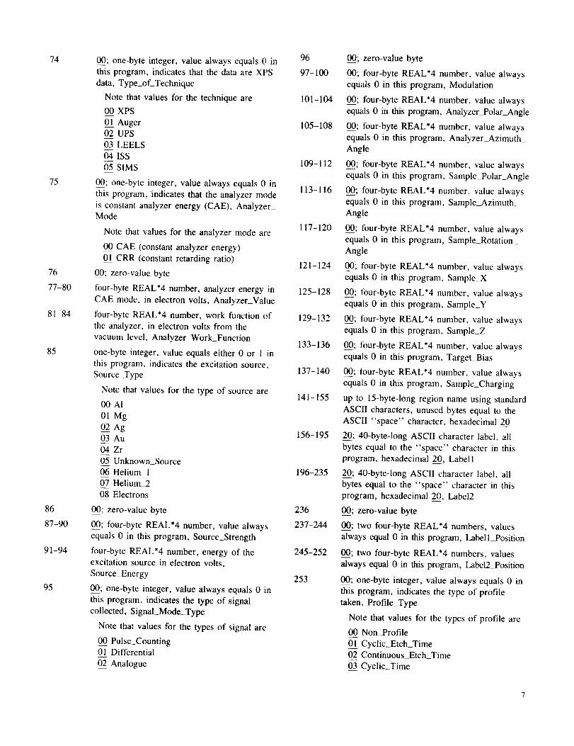
program to certain other types of data file. Each block of thefile header is detailed byte by byte in the appendix.

The first block of the file header provides generalinformation about the data file, such as how many spectral

regions are present and how large they are. The second block

provides space tbr region names up to the maximum number

of regions allowed, although only single-region files are

created by this program. Up to three lines of descriptivecomment can be stored in the third file header block. The

fourth header block, describing the data immediately following

it, contains information about the experimental technique and

floating-point number representation on machines not equipped with the

coprocessor chip. Therefore, care should be exercised if the algorithm

presented herein is rewritten in Pascal. Forlran compilers not listed here

presumably use the machine-efficient byte ordering called for by either an

8087 or an 80287 coprocessor, whether a coprocessor chip is present or not.

However, the byte order of a test file should be checked before trying to use

this program unmodified with other Fortran compilers on a PC.

3The program ASCITOVG is available from COSMIC. University of

Georgia, Athens, GA.

conditions such as the type of scan, the range of the scan, the

excitation source, and the analyzer mode. This header block

would recur once for each spectral region in a multiregion file.

It is located directly ahead of the data blocks that it describes

and separates them from the data of preceding regions. The

fifth and all subsequent blocks in a single-region file contain

the four-byte data values, stored 128 to the block.

The Fortran program itself can be described in terms of a

few basic functions. After checking for the header file

TEMPLATE.XPS in the PC default directory, the programprompts the user for input and output file names to use (with

or without path names) and opens the files. The number of

input points is read, and the minimum and maximum inputvalues in the file are found. The user is then prompted for

information such as the starting and ending scan energies, theelectron analyzer pass energy, the excitation source, the dwell

time, and the number of combined (integrated) scans makingup the data. The user is also asked for the time and date that

the data were collected and is allowed to enter descriptive

comments that will appear in plots of the spectrum. The actualreformatting of the data is then performed to finish the process.

Summary of Results

The incompatible floating-point number representations of

a personal computer (PC) and a Digital Equipment Corporation

(DEC) computer were compared, and a Fortran subroutine

was created to correctly store single-precision, floating-point

numbers on the PC that can be directly read by DEC

computers. A Fortran program using this subroutine waswritten on the PC to convert a column of ASCII-format

numbers into a binary-format file suitable for interactive

analysis with the VGS-5000 Enhanced Data Processing (EDP)

software package. More difficult than the reformatting offloating-point numbers was the creation of the exact data file

header required by the EDP programs for an x-ray photoelectron

spectrum. Experiment parameters, entered by the program

user, are coded into the header format used internally by all

of the VGS-5000 series EDP packages. Whether for externally

captured data or for user-generated test data, the files created

by the program described here should be useful on any of the

VGS-5000 series interactive analysis workstations.

Interested VGS-5000 users may send the author a blank,

formatted, 5.25-in. IBM PC/XT or AT compatible floppy

diskette for a copy of the program source code, executable

program file, and example header file. The program should

also soon become available through the COSMIC software

service operated for NASA by the University of Georgia (call(404) 542-3265 for further information).

Acknowledgments

The author would like to thank Daniel L. Whipple of NASA

Lewis for providing a set of data-handling subroutines useful

in transferring data between any of the many machines atNASA Lewis, including Cray, IBM, VAX, Alliant, Sun, Silicon

Graphics, and personal computers. Although replaced by a

single-purpose subroutine herein, the general-purposesubroutines were most helpful in a first version of this

program. The suggestions and patience of Donald R. Wheeler,

Pierre Steinmann, Douglas Jayne, and Frank S. Honecy of

NASA Lewis while the computers were tied up are appreciated.

The author would like to thank VG Scientific for providingextensive information about their data file header format.

Lewis Research Center

National Aeronautics and Space AdministrationCleveland, Ohio, July 13, 1989

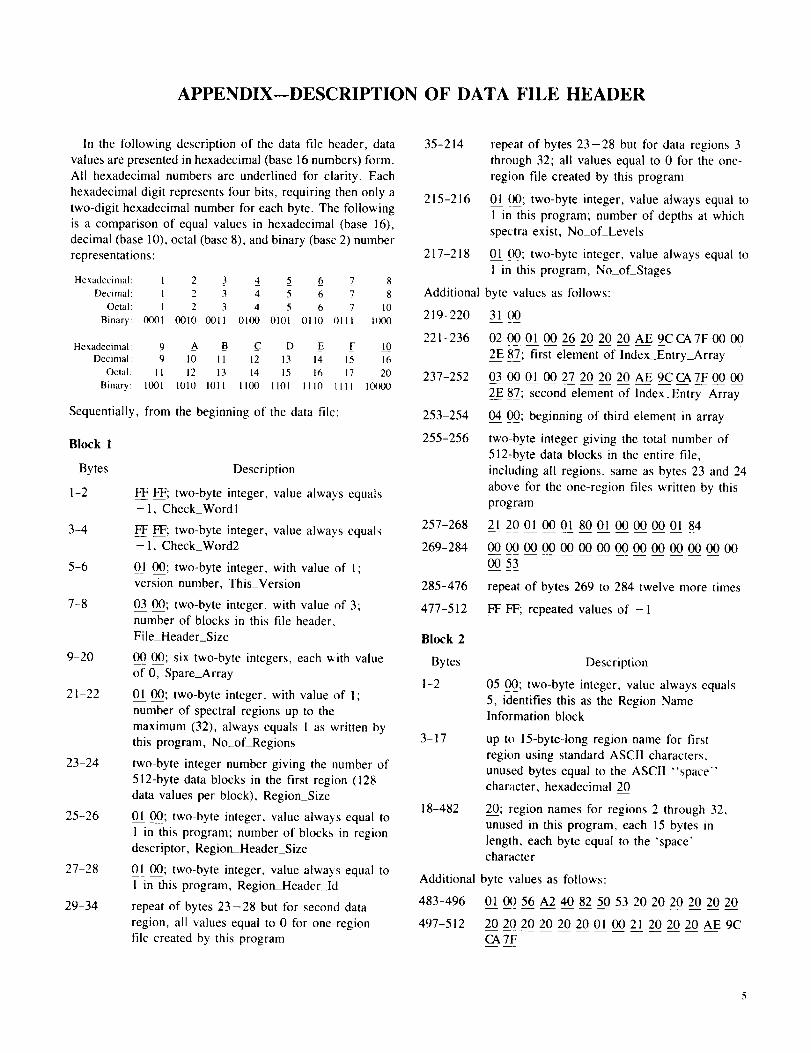
APPENDIX--DESCRIPTION OF DATA FILE HEADER

In the following description of the data file header, data

values are presented in hexadecimal (base 16 numbers) form.

All hexadecimal numbers are underlined for clarity. Each

hexadecimal digit represents four bits, requiring then only a

two-digit hexadecimal number for each byte. The following

is a comparison of equal values in hexadecimal (base 16),

decimal (base 10), octal (base 8), and binary (base 2) number

representations:

Hexadecimal: 1 2 3 4 5 6 7 8Decimal: 1 2 3 4 5 6 7 8

Octal: I 2 3 4 5 6 7 10Binary: 0001 0010 0011 01190 0101 0110 0111 1000

Hexadecimal: _9 A B _C D _E F L0Decimal: 9 10 11 12 13 14 15 16

Octal: I1 12 13 14 15 16 17 20Binary: 1001 1010 1011 II00 1101 1110 till 10_0

Sequentially, from the beginning of the data file:

Block 1

Bytes

1-2

3-4

5-6

7-8

9-20

21-22

23-24

25-26

27-28

29-34

Description

FF FF; two-byte integer, value always equals- 1, Check_Wordl

FF FF; two-byte integer, value always equals- 1, Check_Word2

01 00; two-byte integer, with value of 1;

version number, This_Version

03 00; two-byte integer, with value of 3;number of blocks in this file header.

File_Header_Size

O0 00; six two-byte integers, each with value

of 0, Spare_Array

01 00; two-byte integer, with value of 1;

number of spectral regions up to the

maximum (32), always equals I as written bythis program, No_of_Regions

two-byte integer number giving the number of

512-byte data blocks in the first region (128

data values per block), Region_Size

01 00; two-byte integer, value always equal to

1 in this program; number of blocks in region

descriptor, Region_Header_Size

01 00; two-byte integer, value always equal to

1 in this program, Region_Header_Id

repeat of bytes 23-28 but for second data

region, all values equal to 0 for one-regionfile created by this program

35-214

215-216

217-218

Additional

219-220

221-236

repeat of bytes 23-28 but for data regions 3

through 32; all values equal to 0 for the one-

region file created by this program

01 00; two-byte integer, value always equal to

1 in this program; number of depths at which

spectra exist, No_of_Levels

01 00; two-byte integer, value always equal to

1 in this program, No_of_Stages

byte values as follows:

31 00

02 00 01 00 26 20 20 20 AE 9C CA7F 00 00

2E 87; first element oflndex_Entry_Array

237-252 03 (_ 01 0027 20 20 20 AE 9CCA7F0000

253-254

255-256

257-268

269-284

2E 87; second element of IndexEntry_Array

04 00; beginning of third element in array

two-byte integer giving the total number of512-byte data blocks in the entire file,

including all regions, same as bytes 23 and 24

above for the one-region files written by this

program

21 20 01 00 01 80 Ol 00 00 00 01 84

00 00 00 00 00 00 00 00 00 00 00 00 00 00

285-476

477-512

00 53

repeat of bytes 269 to 284 twelve more times

FF _F; repeated values of - 1

Block 2

Bytes

1-2

Description

05 00; two-byte integer, value always equals

5, identifies this as the Region NameInformation block

3-17 up to 15-byte-long region name for first

region using standard ASCII characters.

unused bytes equal to the ASCII "space"character, hexadecimal 20

18-482 20; region names for regions 2 through 32,

unused in this program, each 15 bytes in

length, each byte equal to the 'space'character

Additional byte values as follows:

483-496 01 00 56 A2 40 82 50 53 20 20 20 20 20 20

497-512 20 20 20 20 20 20 01 0021 20 20 20 AE 9C

CA7F

Block3Bytes

1-2Description

0200;two-byteinteger,valuealwaysequals2, identifiesanInformationblock

3-4 two-byteinteger,dayof themonthdatataken5-6 two-byteinteger,dayof theweekdatataken7-8 two-byteinteger,monthdatataken9-10 two-byteinteger,yeardatataken11-12 two-byteinteger,hourof thedaydatataken,

militaryformatfrom0to 23hours13-14 two-byteinteger,minutesdatataken15-16 two-byteinteger,secondsdatataken17-56 first40-bytecommentline,standardASCII

characters,unusedbytesequaltothe"space"character,hexadecimal20

57-96 2_00;40ASCII"space"characters97-136 second40-bytecommentline,standardASCII

characters,unusedbytesequaltothe"space"character,hexadecimal20

137-176 200;40ASCII"space"characters177-216 third40-bytecommentline,standardASCII

characters,unusedbytesequaltothe'space'character,hexadecimal20

217-482 20;ASCII"space"charactersAdditionalbytevaluesasfollows:483-496 010056A240825053202020202020497-512 202020202020010021202020AE9C

Block 4

Bytes

1-2

3-4

5-6

7-10

11-14

15-18

CA7F

Description

01 00; two-byte integer, value always equals1, identifies block as Data Header, occurs at

beginning of each data region in multiregion

data file, occurs only once in data files

written by this program

00 00; two-byte integer, value always equals0 here, identifies data as a spectrum

two-byte integer, gives the number of datapoints in the data set, Number_of_Channels

four-byte REAL*4 number, starting electron

energy of spectrum, X_Start

four-byte REAL*4 number, ending electron

energy of spectrum. X_End

four-byte REAL*4 number, minimum data

value in any channel of the spectrum,Y_Minimum

19-22

23-26

27

28

29-30

31-34

35-38

39-42

43-64

65-68

69-70

71-72

73

four-byte REAL*4 number, maximum data

value in any channel of the spectrum,Y_Maximum

four-byte REAL*4 number, energy increment

between data points, X_Step

01; one-byte integer, value always equals 1 in

this program, indicates that the X-axis values

are "binding energy", X_Axis_Units

05; one-byte integer, value always equals 5 inthis program, indicates that the Y-axis values

(the data) are "Counts"

Note that values for the X- and Y-axis units

are

00 Kinetic_eV (kinetic energy in electron

volts)

01 Binding_eV (binding energy in electron

volts)

02 AMU (atomic mass units)03 Seconds

04 Degrees05 Counts

06 Count_eV_per_seconds

07 CPS (counts per second)

01 00; two-byte integer, value always equals

1 in this program, No_of_Corresponding_Vars

four-byte REAL*4 number, value equals 0here, Sensitivity_factor

four-byte REAL*4 number, value equals 0

here, Start_Profile_Range

four-byte REAL*4 number, value equals 0

here, End_Profile_Range

00 00; zero values

four-byte REAL*4 number, gives the dwell

time per channel during each scan, inmilliseconds, Dwell_Time

00 00; two-byte integer, value always equals

0 in this program, Signal_to_Noise

two-byte integer, gives the number of scanssummed to produce the data set, No_of_Scans

____;one-byte integer, value always equals 0 in

this program, indicates that the number of

counts per channel were summed from scan to

scan, Point_Repeat

Note that values for the mode of channel

repetition are

00 Integrated

01 Averaged02 Position_Sensitive

74

75

7677-80

81-84

85

8687-90

91-94

95

00; one-byte integer, value always equals 0 inthis program, indicates that the data are XPS

data, Type_of_Technique

Note that values for the technique are

00 XPS

01 Auger02 UPS

03 LEELS

04 ISS

05 SIMS

00; one-byte integer, value always equals 0 in

this program, 'indicates that the analyzer mode

is constant analyzer energy (CAE), Analyzer_Mode

Note that values for the analyzer mode are

00 CAE (constant analyzer energy)

01 CRR (constant retarding ratio)

00; zero-value byte

four-byte REAL*4 number, analyzer energy in

CAE mode, in electron volts, Analyzer_Value

four-byte REAL*4 number, work function of

the analyzer, in electron volts from the

vacuum level, Analyzer_Work_Function

one-byte integer, value equals either 0 or 1 in

this program, indicates the excitation source,

Source_Type

Note that values for the type of source are

00 AI

0A Mg02 Ag03 Au

04 Zr

05 Unknown_Source

06 Helium_l

07 Helium_208 Electrons

00; zero-value byte

00; four-byte REAL*4 number, value always

equals 0 in this program, Source_Strength

four-byte REAL*4 number, energy of the

excitation source in electron volts,Source_Energy

00; one-byte integer, value always equals 0 in

this program, indicates the type of signal

collected, Signal_Mode_Type

Note that values for the types of signal are

00_0Pulse_Counting01 Differential

02 Analogue

96

97-100

101-104

105-108

109-112

113-116

117-120

121-124

125-128

129-132

133-136

137-140

141-155

156-195

196-235

236

237-244

245-252

253

00; zero-value byte

00; four-byte REAL*4 number, value always

equals 0 in this program, Modulation

____;four-byte REAL*4 number, value always

equals 0 in this program, Analyzer_Polar_Angle

00; four-byte REAL*4 number, value always

equals 0 in this program, Analyzer_Azimuth_

Angle

_____;four-byte REAL*4 number, value always

equals 0 in this program, Sample_Polar_Angle

.___; four-byte REAL*4 number, value always

equals 0 in this program, Sample_AzimuthAngle

_; four-byte REAL*4 number, value always

equals 0 in this program, Sample_RotationAngle

0__0_0;tbur-byte REAL*4 number, value always

equals 0 in this program, Sample_X

00; four-byte REAL*4 number, value always

equals 0 in this program, Sample_Y

0_00;lour-byte REAL*4 number, value always

equals 0 in this program. Sample_Z

0___00;tour-byte REAL*4 number, value always

equals 0 in this program, Target_Bias

____;four-byte REAL*4 number, value always

equals 0 in this program, Sample_Charging

up to 15-byte-long region name using standard

ASCII characters, unused bytes equal to theASCII "space" character, hexadecimal 20

2__0_0;40-byte-long ASCII character label, all

bytes equal to the "space" character in this

program, hexadecimal 20, Label l

20; 40-byte-long ASCII character label, all

bytes equal to the "space" character in this

program, hexadecimal 2__0_0,Label2

__; zero-value byte

00; two four-byte REAL*4 numbers, values

always equal 0 in this program, Labell_Position

00; two four-byte REAL*4 numbers, values

always equal 0 in this program, Label2_Position

_; one-byte integer, value always equals 0 in

this program, indicates the type of profiletaken, Profile_Type

Note that values for the types of profile are

00 Non_Profile

0._11Cyclic_Etch_Time02 Continuous_Etch_Time

03 Cyclic_Time

Report Documentation PageNational Aeronaulics andSpace Adm_nlstra!,on

1. Report No. 2. Government Accession No. 3. Recipient's Catalog No.

NASA TP-2957

4. Title and Subtitle

Fortran Program for X-Ray Photoelectron Spectroscopy Data Reformatting

7. AuthOr(s)

Phillip B. Abel

9. Performing Organization Name and Address

National Aeronautics and Space Administration

Lewis Research Center

Cleveland, Ohio 44135-3191

12. Sponsoring Agency Name and Address

National Aeronautics and Space Administration

Washington, D.C. 20546-0001

5. Report Date

November 1989

6. Performing Organization Code

8. Performing Organization Report No.

E-4867

10. Work Unit No.

506-43-11

11. Contract or Grant No.

13. Type of Report and Period Covered

Technical Paper

14. Sponsoring Agency Code

15. Supplementary Notes

16. Abstract

A Fortran program has been written for use on an IBM PC/XT or AT or compatible microcomputer (personal

computer, PC) that converts a column of ASCII-format numbers into a binary-format file suitable for interactive

analysis on a Digital Equipment Corporation (DEC) computer running the VGS-5000 Enhanced Data Processing

(EDP) software package. The incompatible floating-point number representations of the two computers were

compared, and a subroutine was created to correctly store floating-point numbers on the IBM PC, which can be

directly read by the DEC computer. Any file transfer protocol having provision for binary data can be used to

transmit the resulting file from the PC to the DEC machine. The data file header required by the EDP programs

for an x-ray photoelectron spectrum is also written to the file. The user is prompted for the relevant experimental

parameters, which are then properly coded into the format used internally by all of the VGS-5000 series EDP

packages.

17. Key Words (Suggested by Author(s))

X-ray; Photoelectron spectroscopy; VG Escalab;

Surface properties; VAMAS

18. Distribution Statement

Unclassified - Unlimited

Subject Category 76

19. Security Classif. (of this report) 20. Security Ctassif. (of this page) 21. No of pages 22. Price*

Unclassified Unclassified 12 A03

NASAFORMle26 OCt 86 *For sale by the National Technical Information Service, Springfield, Virginia 22161

NASA-Langley, 1989

-r

._--_i- " National Aeron_ bnd - •

L --..... Space Admird_ ..

" - .Code NTT-4 °=;_"

Washington. D_--_ 20546-0001 /

iD_ltcea! Business ' " •

-_ Penally to_ ptrvate _ $300 ; - -_

q

I I .

J "_- !

. . -_

- __ ;__---

_ ;r --7-" -

\

BULK RATE

POSTAGE & FEES PAIDNASA

Permit No. G-27

POSTMASTER: If Undeliverable (Section 158Postal Manual) Do No! Return


Recommended