Model 5081-C-FF/FI FOUNDATION Fieldbus ® Two-Wire Conductivity Transmitter Instruction Sheet PN 51A-5081C-FF-FI/rev.C January 2011 Your purchase from Rosemount Analytical, Inc. has result- ed in one of the finest instruments available for your par- ticular application. These instruments have been designed, and tested to meet many national and interna- tional standards. Experience indicates that its perform- ance is directly related to the quality of the installation and knowledge of the user in operating and maintaining the instrument. To ensure their continued operation to the design specifications, personnel should read this manual thoroughly before proceeding with installation, commis- sioning, operation, and maintenance of this instrument. If this equipment is used in a manner not specified by the manufacturer, the protection provided by it against haz- ards may be impaired. • Failure to follow the proper instructions may cause any one of the following situations to occur: Loss of life; per- sonal injury; property damage; damage to this instru- ment; and warranty invalidation. • Ensure that you have received the correct model and options from your purchase order. Verify that this manu- al covers your model and options. If not, call 1-800- 854-8257 or 949-757-8500 to request correct manual. • For clarification of instructions, contact your Rosemount representative. • Follow all warnings, cautions, and instructions marked on and supplied with the product. • Use only qualified personnel to install, operate, update, program and maintain the product. • Educate your personnel in the proper installation, oper- ation, and maintenance of the product. • Install equipment as specified in the Installation section of this manual. Follow appropriate local and national codes. Only connect the product to electrical and pres- sure sources specified in this manual. • Use only factory documented components for repair. Tampering or unauthorized substitution of parts and procedures can affect the performance and cause unsafe operation of your process. • All equipment doors must be closed and protective cov- ers must be in place unless qualified personnel are per- forming maintenance. • If this equipment is used in a manner not specified by the manufacturer, the protection provided by it against hazards may be impaired. ESSENTIAL INSTRUCTIONS READ THIS PAGE BEFORE PROCEEDING! WARNING To prevent ignition of flammable or combustible atmospheres, disconnect power before servicing or understand and adhere to the manufacturer's live maintenance procedures. WARNING Substitution of components may impair Intrinsic Safety or suitability for Division 2. WARNING Do not remove or replace while circuit is live unless area is known to be non-hazardous. WARNING Explosion Hazard - Do not disconnect equipment unless area is known to be non-hazardous. For additional information, please visit our website at www.emersonprocess.com/raihome/liquid/.
Transcript
Model 5081-C-FF/FI
FOUNDATION Fieldbus® Two-Wire
Conductivity Transmitter
Instruction SheetPN 51A-5081C-FF-FI/rev.C
January 2011
Your purchase from Rosemount Analytical, Inc. has result-ed in one of the finest instruments available for your par-t icular application. These instruments have beendesigned, and tested to meet many national and interna-tional standards. Experience indicates that its perform-ance is directly related to the quality of the installation andknowledge of the user in operating and maintaining theinstrument. To ensure their continued operation to thedesign specifications, personnel should read this manualthoroughly before proceeding with installation, commis-sioning, operation, and maintenance of this instrument. Ifthis equipment is used in a manner not specified by themanufacturer, the protection provided by it against haz-ards may be impaired.
• Failure to follow the proper instructions may cause anyone of the following situations to occur: Loss of life; per-sonal injury; property damage; damage to this instru-ment; and warranty invalidation.
• Ensure that you have received the correct model andoptions from your purchase order. Verify that this manu-al covers your model and options. If not, call 1-800-854-8257 or 949-757-8500 to request correct manual.
• For clarification of instructions, contact your Rosemountrepresentative.
• Follow all warnings, cautions, and instructions markedon and supplied with the product.
• Use only qualified personnel to install, operate, update,program and maintain the product.
• Educate your personnel in the proper installation, oper-ation, and maintenance of the product.
• Install equipment as specified in the Installation sectionof this manual. Follow appropriate local and nationalcodes. Only connect the product to electrical and pres-sure sources specified in this manual.
• Use only factory documented components for repair.Tampering or unauthorized substitution of parts andprocedures can affect the performance and causeunsafe operation of your process.
• All equipment doors must be closed and protective cov-ers must be in place unless qualified personnel are per-forming maintenance.
• If this equipment is used in a manner not specified bythe manufacturer, the protection provided by it againsthazards may be impaired.
ESSENTIAL INSTRUCTIONSREAD THIS PAGE BEFORE PROCEEDING!
WARNINGTo prevent ignition of flammable or combustibleatmospheres, disconnect power before servicingor understand and adhere to the manufacturer'slive maintenance procedures.
WARNINGSubstitution of components may impair IntrinsicSafety or suitability for Division 2.
WARNINGDo not remove or replace while circuit is liveunless area is known to be non-hazardous.
WARNINGExplosion Hazard - Do not disconnect equipmentunless area is known to be non-hazardous.
For additional information, please visit our website
at www.emersonprocess.com/raihome/liquid/.
MODEL 5081-C-FF/FI SPECIFICATIONS
PHYSICAL SPECIFICATIONS
HOUSING: Cast aluminum with epoxy coating. NEMA
4X (IP65) and NEMA 7B. Neoprene O-ring cover
seals. 160.5 mm x 175.3 mm x 161.3 mm (6.3 in.
x 6.9 in. x 6.4 in.)
DIAMETER: 155.4 mm (6.1 in.)
ELECTRICAL CONDUIT OPENINGS: 3/4 in. FNPT
POWER SUPPLY AND LOAD: A power supply voltage
of 9 Vdc to 32 Vdc at 22 mA is required; Intrinsically
Safe installations may be limited to a maximum of 2-3
transmitters per node, depending on the barrier used.
LOCAL READOUT:
Main Display is 4 digits, 20 mm tall (0.8 in.)
Message Display is ten digits, 7 mm tall (0.3 in.)
AUTOMATIC TEMPERATURE COMPENSATION:
3-wire Pt100 or Pt1000 RTD
Conductivity: 0 to 200 °C (32 to 392 °F)
Resistivity: 0 to 100 °C (32 to 212°F)
Low Conductivity: 0 to 100 °C (32 to 212 °F)
AMBIENT TEMPERATURE: -20 to 65° C (-4 to 149° F)
RELATIVE HUMIDITY: 0-95% with enclosure sealed.
CE: EMI/RFI certified:
EN61326
HAZARDOUS AREA CLASSIFICATION:Intrinsic Safety:
Class I, II, III, Div. 1
Groups A-G
T4 Tamb = 70°C
Exia Entity
Class I, Groups A-D
Class II, Groups E-G
Class III
T4 Tamb = 70°C
ATEX 0600
II 1 G
Baseefa03ATEX0099
EEx ia IIC T4
Tamb = -20°C to +65°C
Non-Incendive:
Class I, Div. 2, Groups A-D
Dust Ignition Proof
Class II & III, Div. 1, Groups E-G
NEMA 4X Enclosure
Class I, Div. 2, Groups A-D
Suitable for Class II, Div. 2, Groups E-G
T4 Tamb = 70°C
Explosion-Proof:
Class I, Div. 1, Groups B-D
Class II, Div. 1, Groups E-G
Class III, Div. 1
Class I, Groups B-D
Class II, Groups E-G
Class III
Tamb = 65°C max
TRANSMITTER SPECIFICATIONS @ 25°C
MEASURED RANGE: 0-20,000 µS/cm
ACCURACY: ± 0.5% of reading and ± 0.001 µS/cm
REPEATABILITY: ± 0.25% of reading
STABILITY: 0.25% of output range/month, non-cumu-
lative
AMBIENT TEMPERATURE COEFFICIENT:
± 0.05% of reading/°C
TEMPERATURE SLOPE ADJUSTMENT: 0-5%/°C
Other temperature compensation algorithms: ultra-
pure water compensation, cation conductivity, or
raw (uncompensated) conductivity.
COMPATIBLE RTD: 100Ω or 1000Ω with Automatic
Recognition
LOOP SPECIFICATIONS
ACCURACY: under controlled laboratory conditions at
25°C (77°F) with perfectly calibrated ENDURANCE
sensor of appropriate cell constant:
up to 5,000 µS/cm: ± 1.0% and ± 2 least signifi-
cant digit
from 5,000 to 20,000: ± 2% of reading and ± 2
least significant digit
SENSOR SELECTION GUIDELINES
Note: The conductivity values shown in the above chart arefor UNCOMPENSATED (or RAW) conductivity at 25°C.Maximum range values will vary due to temperaturecompensation selection, process temperature, and otherprocess conditions.
Cell Constant Suggested Conductivity Range
0.01/cm up to 50 µS/cm
0.1/cm 1.0 to 500 µS/cm
1.0/cm 10 to 20,000 µS/cm
MODEL 5081-C-FF/FI INFRARED REMOTE CONTROLLER
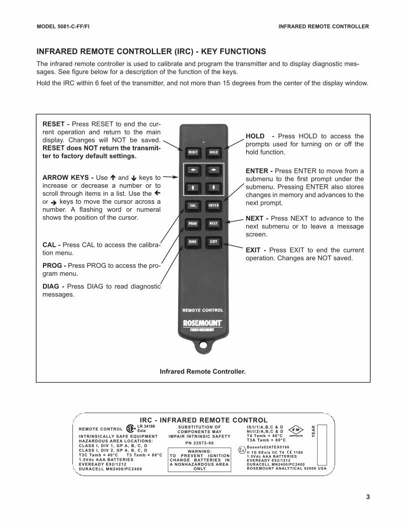
INFRARED REMOTE CONTROLLER (IRC) - KEY FUNCTIONS
The infrared remote controller is used to calibrate and program the transmitter and to display diagnostic mes-
sages. See figure below for a description of the function of the keys.
Hold the IRC within 6 feet of the transmitter, and not more than 15 degrees from the center of the display window.
Infrared Remote Controller.
RESET - Press RESET to end the cur-
rent operation and return to the main
display. Changes will NOT be saved.
RESET does NOT return the transmit-
ter to factory default settings.
CAL - Press CAL to access the calibra-
tion menu.
PROG - Press PROG to access the pro-
gram menu.
DIAG - Press DIAG to read diagnostic
messages.
HOLD - Press HOLD to access the
prompts used for turning on or off the
hold function.
ARROW KEYS - Use é and ê keys to
increase or decrease a number or to
scroll through items in a list. Use the çor è keys to move the cursor across a
number. A flashing word or numeral
shows the position of the cursor.
ENTER - Press ENTER to move from a
submenu to the first prompt under the
submenu. Pressing ENTER also stores
changes in memory and advances to the
next prompt.
NEXT - Press NEXT to advance to the
next submenu or to leave a message
screen.
EXIT - Press EXIT to end the current
operation. Changes are NOT saved.
REMOTE CONTROL
INTRINSICALLY SAFE EQUIPMENTHAZARDOUS AREA LOCATIONS:CLASS I , DIV 1, GP A, B, C, DCLASS I , DIV 2, GP A, B, C, DT3C Tamb = 40°C T3 Tamb = 80°C1.5Vdc AAA BATTERIESEVEREADY E92/1212DURACELL MN2400/PC2400
IS/ I /1 /A,B,C & DNI / I /2 /A,B,C & DT4 Tamb = 40°C T3A Tamb = 80°C
Baseefa02ATEX0198
I I 1G EExia I IC T4 11801.5Vdc AAA BATTERIESEVEREADY E92/1212DURACELL MN2400/PC2400ROSEMOUNT ANALYTICAL 92606 USA
WARNING:TO PREVENT IGNIT IONCHANGE BATTERIES INA NONHAZARDOUS AREA
ONLY
IRC - INFRARED REMOTE CONTROLLR 34186Exia
SUBSTITUTION OF COMPONENTS MAY
IMPAIR INTRINSIC SAFETY
PN 23572-00
YE
AR
3
4
Nus!DBM
uFNQ!TMPQF1
BcT D!
1!bjs
6192.D.Gg
DFMM!DPoTu
TpGu
DBM!G
IBse
uTMPQF1
GbVMUt
611125.0C
CAL keyPROG keyDIAG keyHOLD key
Model 5081-C-FF/FI
Process Display Screen
µS/cm
DBMJcsBuF
DFMM!DPoTu
TFoTPs!1
uFNQ!BeK
uFNQ
eJTQMBZ
TFuVQ!DvTU
sBohF
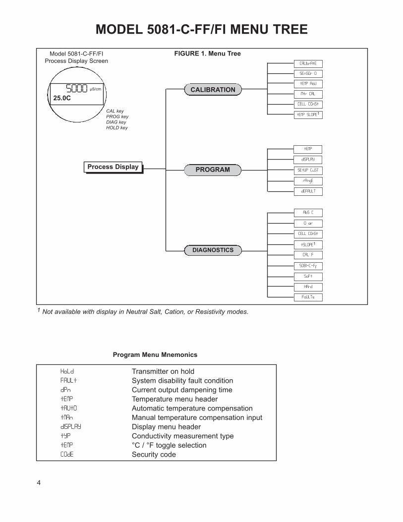
PROGRAMProcess Display
FIGURE 1. Menu Tree
1 Not available with display in Neutral Salt, Cation, or Resistivity modes.
MODEL 5081-C-FF/FI MENU TREE
Program Menu Mnemonics
IpMe Transmitter on hold
GBVMu System disability fault condition
eQo Current output dampening time
uFNQ Temperature menu header
uBVuP Automatic temperature compensation
uNBo Manual temperature compensation input
eJTQMBZ Display menu header
uZQ Conductivity measurement type
uFNQ! °C / °F toggle selection
DPeF Security code
CALIBRATION
DIAGNOSTICS
eFGBVMU
5
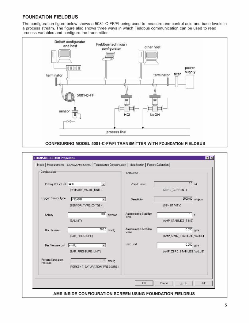
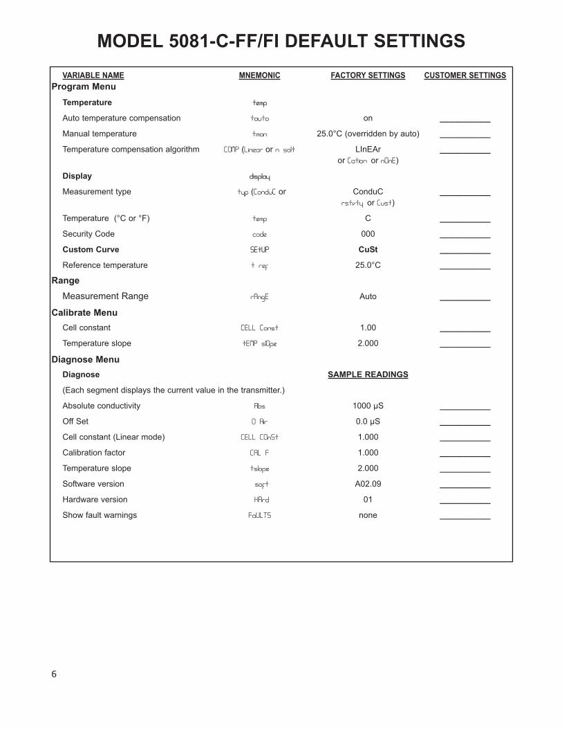
FOUNDATION FIELDBUS
The configuration figure below shows a 5081-C-FF/FI being used to measure and control acid and base levels ina process stream. The figure also shows three ways in which Fieldbus communication can be used to readprocess variables and configure the transmitter.
CONFIGURING MODEL 5081-C-FF/FI TRANSMITTER WITH FOUNDATION FIELDBUS
AMS INSIDE CONFIGURATION SCREEN USING FOUNDATION FIELDBUS
6
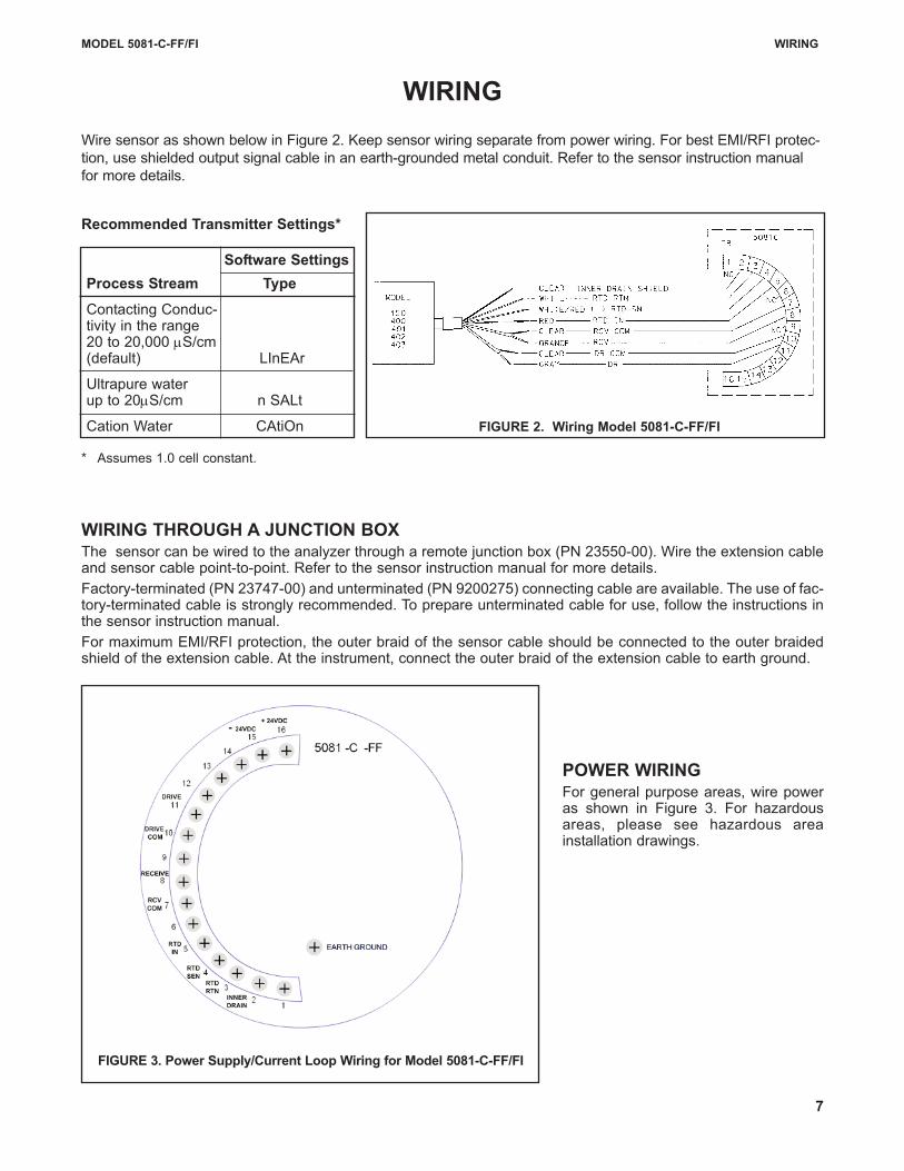
MODEL 5081-C-FF/FI DEFAULT SETTINGS
VARIABLE NAME MNEMONIC FACTORY SETTINGS CUSTOMER SETTINGS
Program Menu
Temperature ufnq
Auto temperature compensation ubvup on ___________
Manual temperature unbo 25.0°C (overridden by auto) ___________
Temperature compensation algorithm DPNQ (Mjofbs or o!tbmu LInEAr ___________
or Dbujpo!or oPoF)
Display ejtqmbz
Measurement type uzq (DpoevD or ConduC ___________
stuwuz!or Dvtu)
Temperature (°C or °F) ufnq C ___________
Security Code dpef 000 ___________
Custom Curve TFuVQ CuSt ___________
Reference temperature u!sfg 25.0°C ___________
Range
Measurement Range sBohF Auto ___________
Calibrate Menu
Cell constant DFMM!Dpotu 1.00 ___________
Temperature slope uFNQ!tmPqf 2.000 ___________
Diagnose Menu
Diagnose SAMPLE READINGS
(Each segment displays the current value in the transmitter.)
WIRING THROUGH A JUNCTION BOXThe sensor can be wired to the analyzer through a remote junction box (PN 23550-00). Wire the extension cableand sensor cable point-to-point. Refer to the sensor instruction manual for more details.
Factory-terminated (PN 23747-00) and unterminated (PN 9200275) connecting cable are available. The use of fac-tory-terminated cable is strongly recommended. To prepare unterminated cable for use, follow the instructions inthe sensor instruction manual.
For maximum EMI/RFI protection, the outer braid of the sensor cable should be connected to the outer braidedshield of the extension cable. At the instrument, connect the outer braid of the extension cable to earth ground.
POWER WIRINGFor general purpose areas, wire poweras shown in Figure 3. For hazardousareas, please see hazardous areainstallation drawings.
FIGURE 3. Power Supply/Current Loop Wiring for Model 5081-C-FF/FI
7
WIRING
Wire sensor as shown below in Figure 2. Keep sensor wiring separate from power wiring. For best EMI/RFI protec-
tion, use shielded output signal cable in an earth-grounded metal conduit. Refer to the sensor instruction manual
for more details.
Recommended Transmitter Settings*
* Assumes 1.0 cell constant.
Software Settings
Process Stream Type
Contacting Conduc-tivity in the range 20 to 20,000 μS/cm (default) LInEAr
Ultrapure waterup to 20μS/cm n SALt
Cation Water CAtiOn FIGURE 2. Wiring Model 5081-C-FF/FI
MODEL 5081-C-FF/FI INSTALLATION
INSTALLATION
UNPACKING AND INSPECTION
Inspect the shipping container. If it is damaged, contact the shipper immediately for instructions. Save the box. If
there is no apparent damage, unpack the container. Be sure all items shown on the packing list are present. If
items are missing, notify Rosemount Analytical immediately.
ROTATING THE DISPLAY
The Model 5081-C-FF/FI display can be rotated 90° left or right. Disengage the cover lock and remove the front
cover. Remove the three screws holding the PCB stack and gently lift the display board. Do not disengage the rib-
bon cable between the display board and the CPU board. Rotate the display. The black infrared sensor will be at
the top of the display.
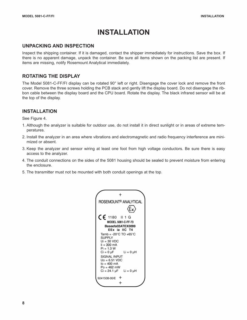
INSTALLATION
See Figure 4.
1. Although the analyzer is suitable for outdoor use, do not install it in direct sunlight or in areas of extreme tem-
peratures.
2. Install the analyzer in an area where vibrations and electromagnetic and radio frequency interference are mini-
mized or absent.
3. Keep the analyzer and sensor wiring at least one foot from high voltage conductors. Be sure there is easy
access to the analyzer.
4. The conduit connections on the sides of the 5081 housing should be sealed to prevent moisture from entering
the enclosure.
5. The transmitter must not be mounted with both conduit openings at the top.
8
9
MODEL 5081-C-FF/FI INSTALLATION
MILLIMETER
INCH
FIGURE 4. Mounting Model 5081-C-FF/FI
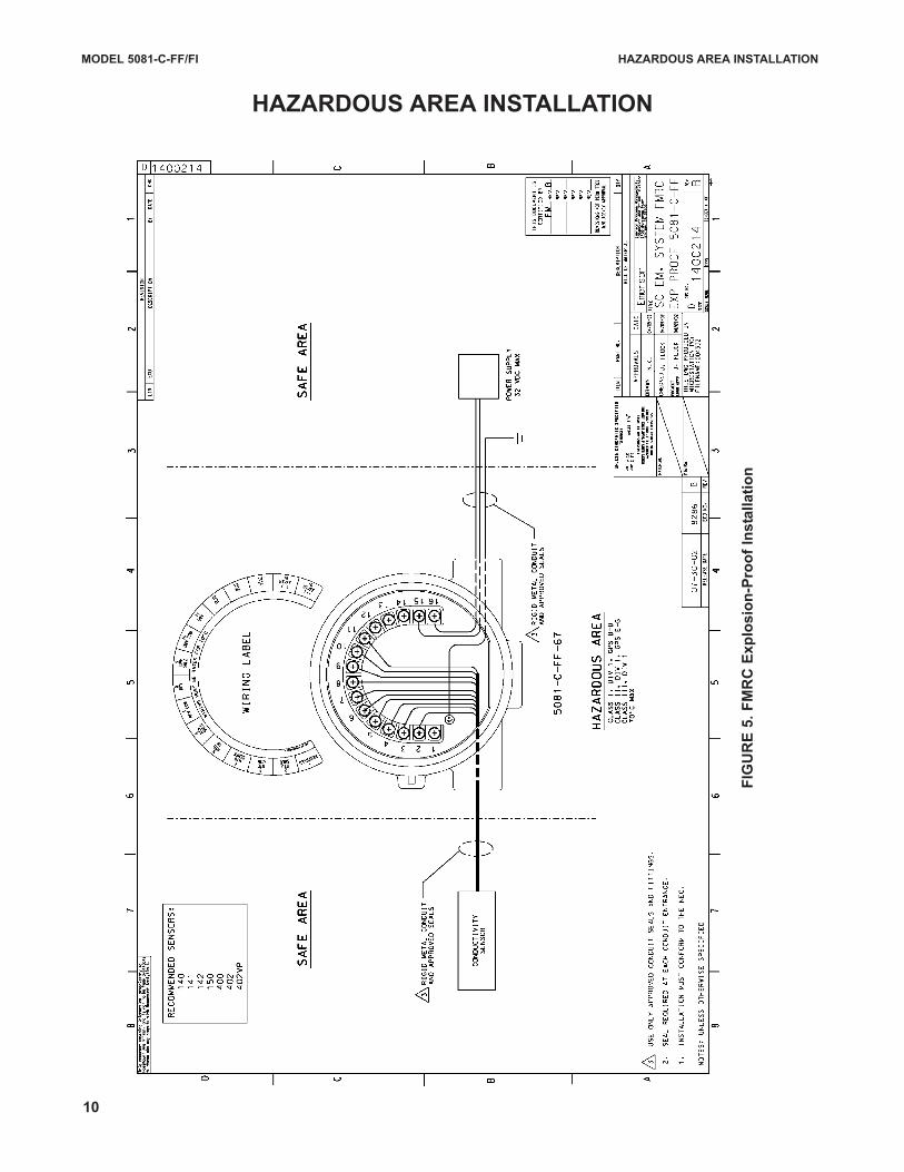
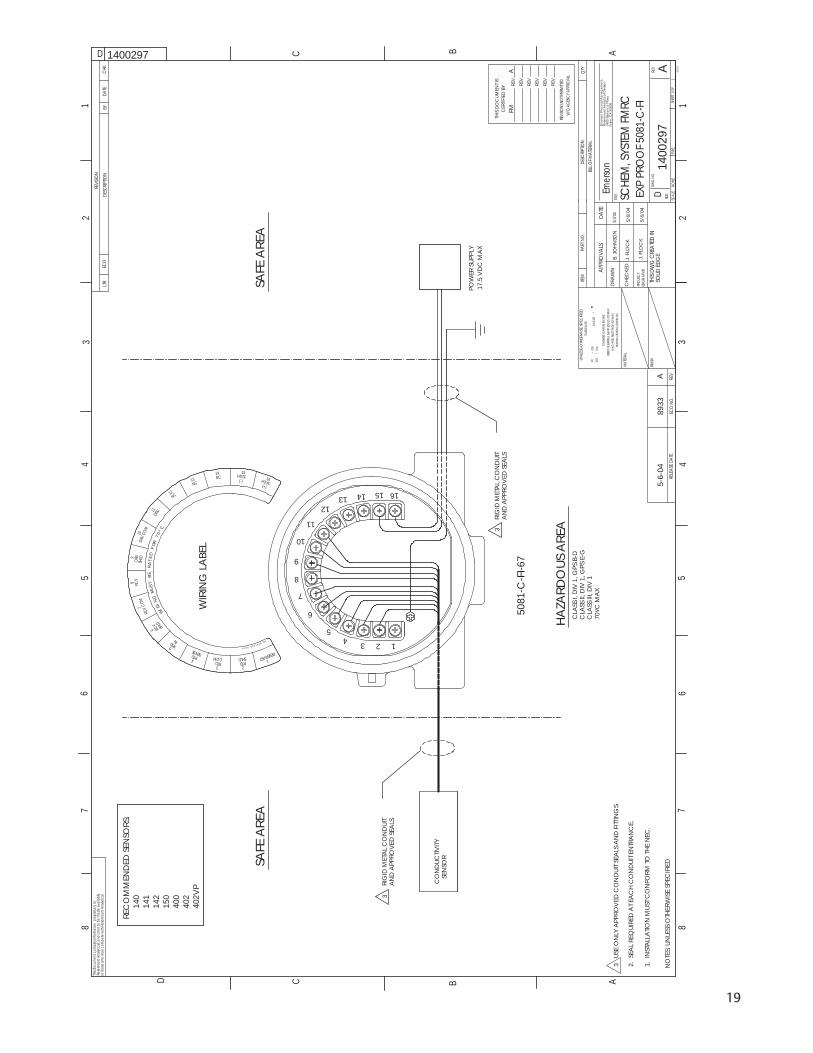
MODEL 5081-C-FF/FI HAZARDOUS AREA INSTALLATION
HAZARDOUS AREA INSTALLATION
FIG
UR
E 5
. F
MR
C E
xp
losio
n-P
roo
f In
sta
llati
on
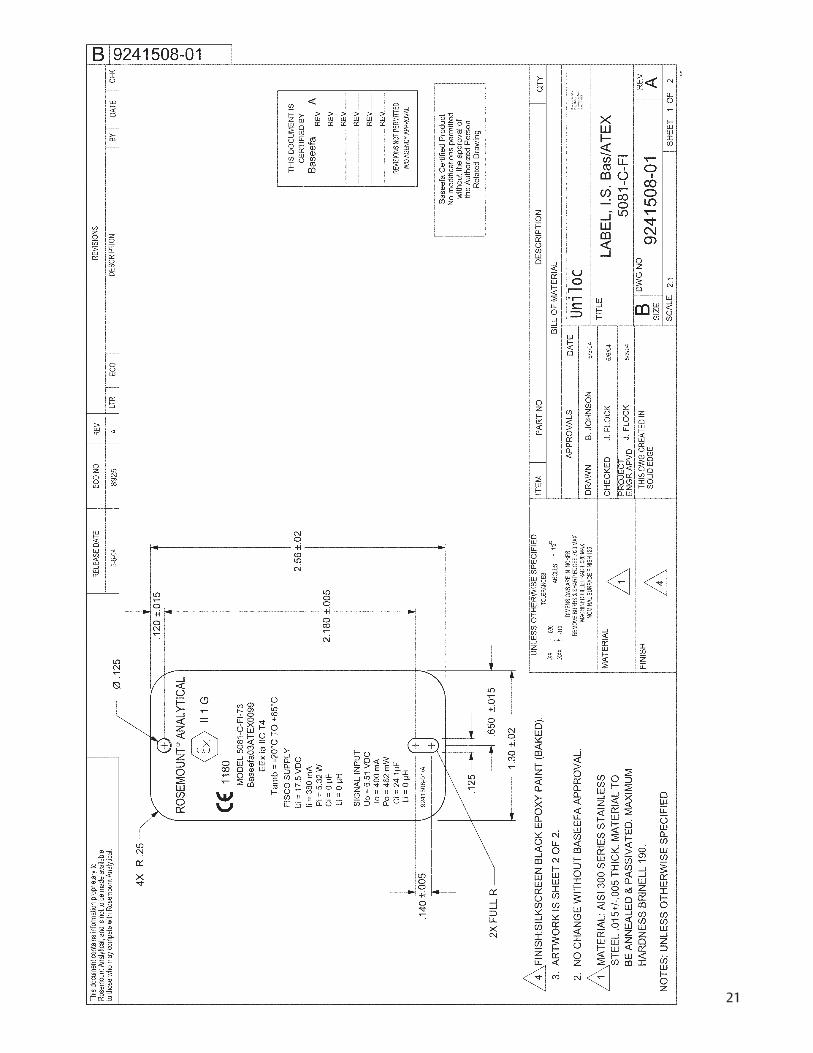
10
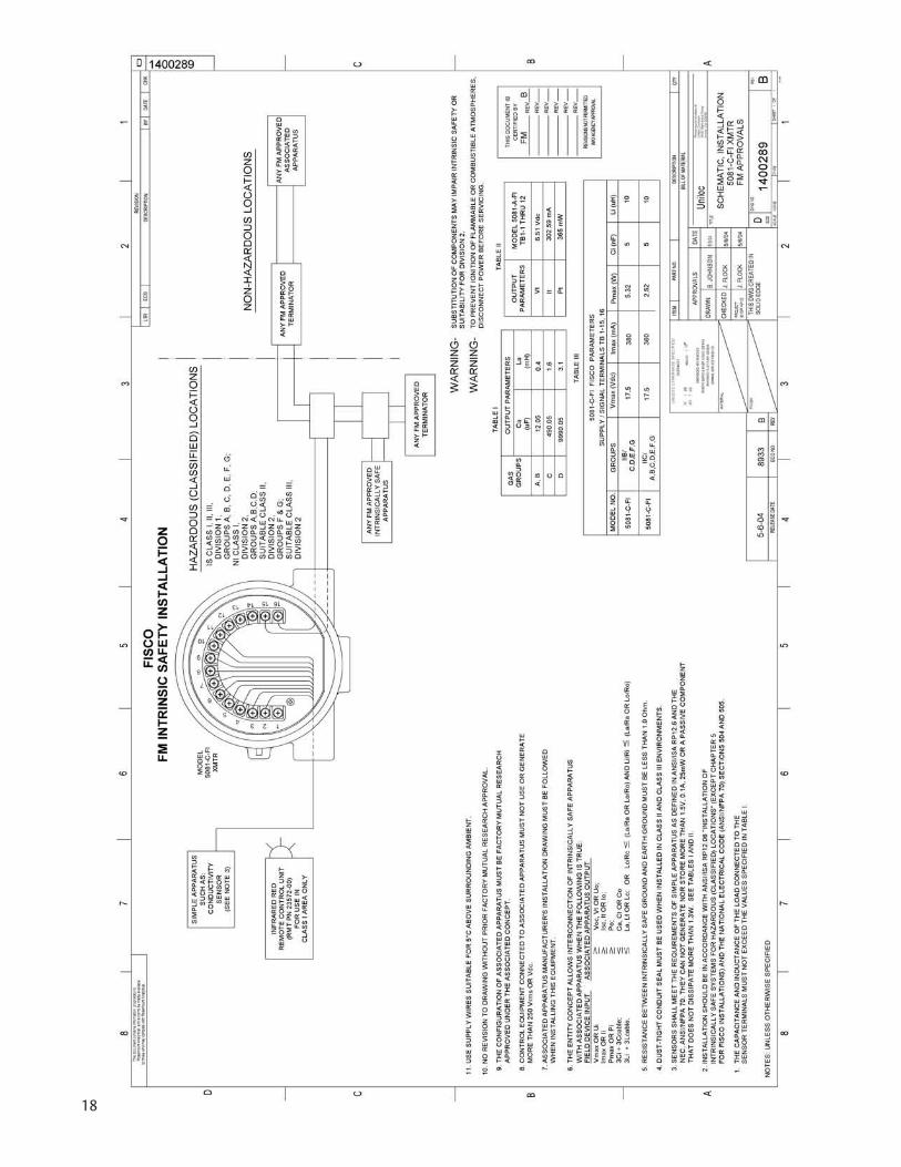
FIG
UR
E 6
. F
M H
azard
ou
s A
rea A
pp
roval
Lab
el
11
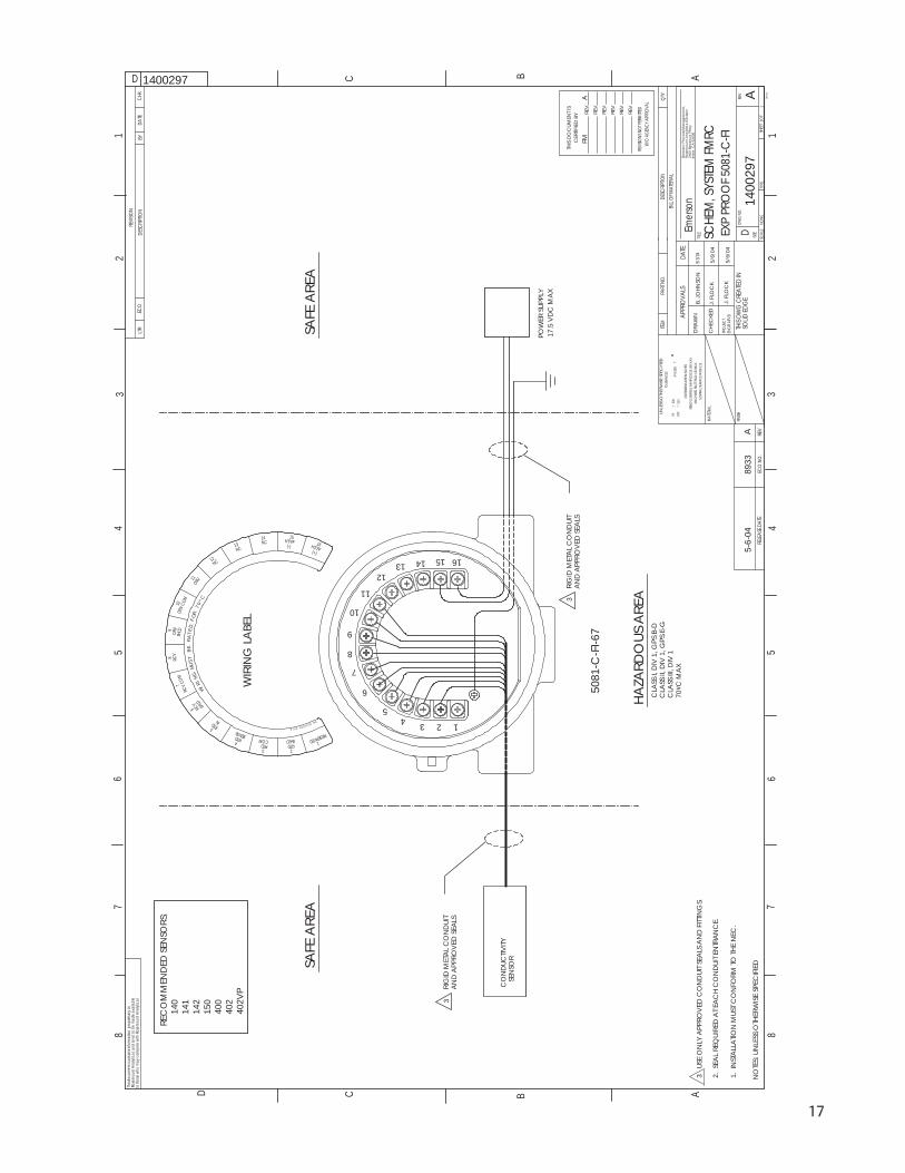
FIG
UR
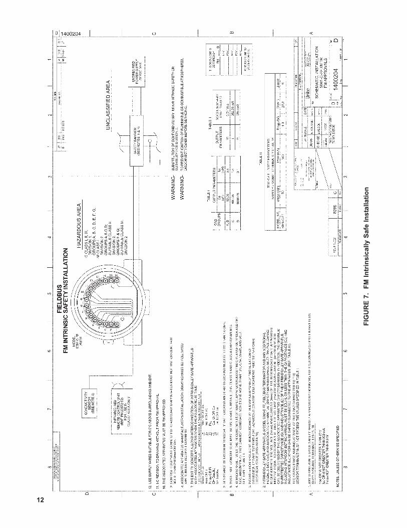
E 7
. F
M I
ntr
insic
ally S
afe
In
sta
llati
on
12
FIG
UR
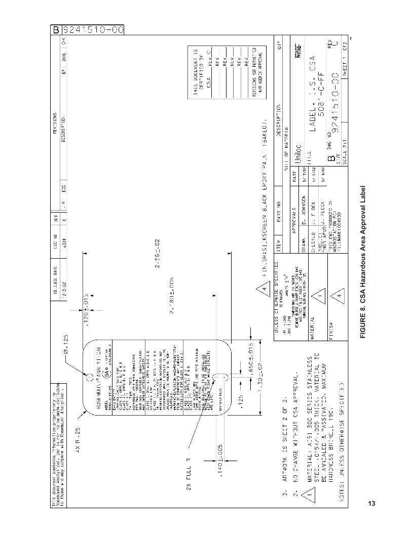
E 8
. C
SA
Hazard
ou
s A
rea A
pp
roval
Lab
el
13
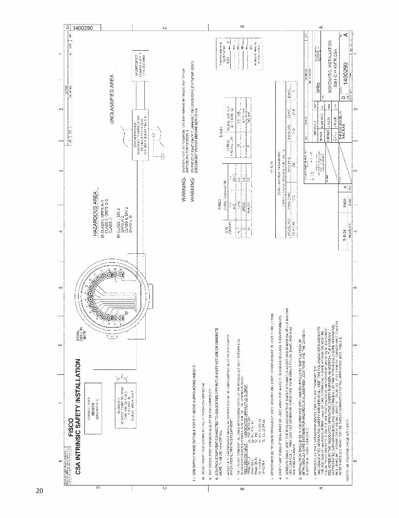
FIG
UR
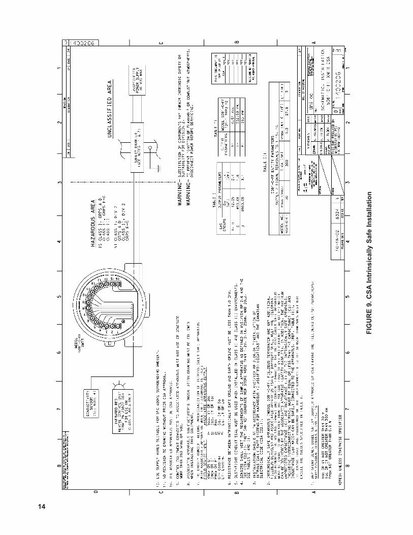
E 9
. C
SA
In
trin
sic
ally S
afe
In
sta
llati
on
14
15
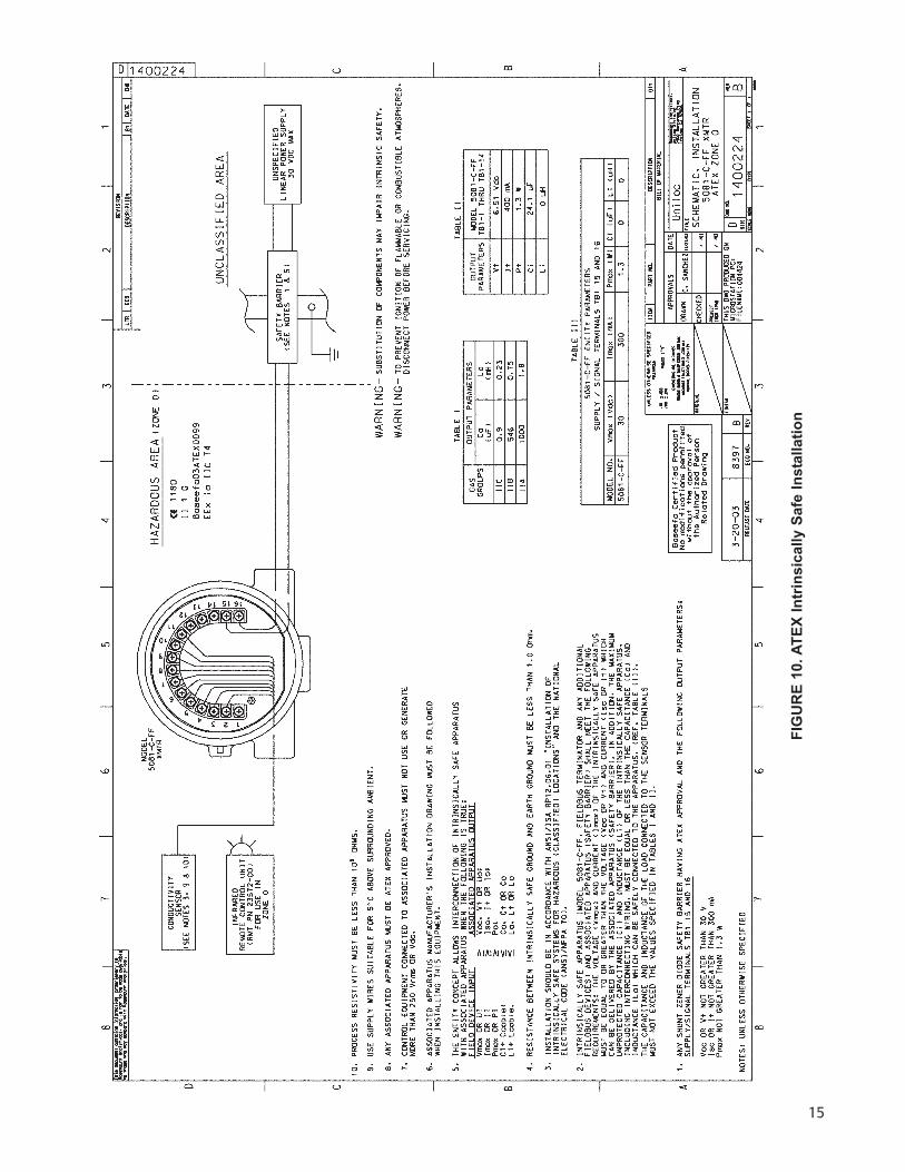
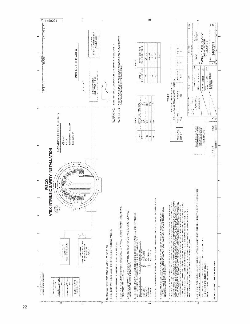
FIG
UR
E 1
0. A
TE
X I
ntr
insic
ally S
afe
In
sta
llati
on
16
17
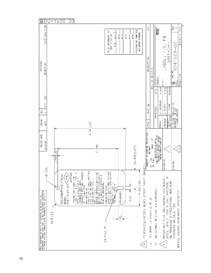
UNLE
SS O
THER
WIS
E SP
ECIF
IED
DIM
ENSIO
NS A
RE IN
INCH
ESRE
MOVE
BURR
S & SH
ARP E
DGES
.020
MAX
MAC
HINED
FILLE
T RAD
II .02
0 MAX
FINISH
MATE
RIAL
PROJ
ECT
ENGR
APV
D
SIZE
DWG
NO.
REV
TITLE
SCAL
ETY
PE
CHE
CKE
D
DRA
WN
THIS
DWG
CRE
ATED
IN
DATE
DESC
RIPTIO
NBIL
L OF M
ATER
IAL
QTY
ITEM
PART
NO.
RELE
ASE D
ATE
ECO
NO.
REV
LTREC
ODE
SCRIP
TION
BYDA
TERE
VISIO
NCH
K
SOLID
EDG
E
TOLE
RANC
ES
-+ -
+AN
GLES
-+.01
0.XX
X.XX
.030
APPR
OVA
LS
D
106
-01
AB
23
455
43
21
CD
1400
297
ANO
NESH
EET
OF
11
1400297
A
NOMI
NAL S
URFA
CE FI
NISH
125
2400
Bar
ranc
a Pk
wy
Irvin
e, C
A 9
2606
5/3/04
Emer
son
Emer
son
Proc
ess M
anag
emen
t,Ro
sem
ount
Ana
lytic
al D
ivisi
on
B. J
OHN
SON
EXP
PRO
OF 5
081-
C-F
I
This d
ocum
ent c
onta
ins in
form
ation
pro
priet
ary t
oRo
sem
ount
Ana
lytica
l, and
is no
t to
be m
ade
avai
lable
to th
ose
who
may
com
pete
with
Rose
mou
nt A
nalyt
ical.
NO
TES:
UN
LESS
OTH
ERW
ISE
SPEC
IFIE
D
87
6
87
6
ABD C
1. I
NST
ALLA
TION
MUS
T CO
NFO
RM TO
THE
NEC
.
2. S
EAL
REQ
UIRE
D A
T EAC
H C
ON
DUI
T EN
TRAN
CE.
3 U
SE O
NLY
APP
ROVE
D C
ON
DUI
T SEA
LS A
ND
FITT
ING
S. SC
HEM
, SYS
TEM
FMRC
WIR
ING
LAB
EL
3
3
12345
6
7
8
9
10
11
1213 14 15 16
POW
ER S
UPPL
Y
508
1-C
-FI-6
7
RIG
ID M
ETAL
CO
ND
UIT
AND
APP
ROVE
D S
EALS
RIG
ID M
ETAL
CO
ND
UIT
AND
APP
ROV
ED S
EALS
SAFE
ARE
ASA
FE A
REA
THIS
DO
CUM
ENT I
SC
ERTIF
IED
BY RE
V
REV
REV
REV
REV
REV
REVIS
IONS
NOT
PERM
ITTED
W/O
AGEN
CY A
PPRO
VAL
5-6-
04
893
3
17.
5 VD
C M
AX
REC
OM
MEN
DED
SEN
SORS
:
140
1
41
142
1
50
400
4
02
402
VP
CO
ND
UCTIV
ITY
SEN
SOR
3RTDCOM
6 RCV SHLD
7RC
V CO
M
8 RCV
9DR
VSH
LD10
DRV C
OM
2RTDSHLD
5 RTD IN
12NC
13NC
4RTD SENSE
1RESERVED
15HT/FF
(-) 16HT/FF(+)
14NC
11DRV
WIRI
NGMU
STB
ER
AT
ED
F OR
70^C
PN9241520-00/A
HAZA
RDO
US A
REA
CLA
SS I,
DIV
1, G
PS B
-DC
LASS
II, D
IV 1
, GPS
E-G
CLA
SS II
I, D
IV 1
7
0 C
MAX
v
J. F
LOC
K5/
6/04
J. F
LOC
K5/
6/04
FM
A
18
19
UNLE
SS O
THER
WIS
E SP
ECIF
IED
DIM
ENSIO
NS A
RE IN
INCH
ESRE
MOVE
BURR
S & SH
ARP E
DGES
.020
MAX
MAC
HINED
FILLE
T RAD
II .02
0 MAX
FINISH
MATE
RIAL
PROJ
ECT
ENGR
APV
D
SIZE
DWG
NO.
REV
TITLE
SCAL
ETY
PE
CHE
CKE
D
DRA
WN
THIS
DWG
CRE
ATED
IN
DATE
DESC
RIPTIO
NBIL
L OF M
ATER
IAL
QTY
ITEM
PART
NO.
RELE
ASE D
ATE
ECO
NO.
REV
LTREC
ODE
SCRIP
TION
BYDA
TERE
VISIO
NCH
K
SOLID
EDG
E
TOLE
RANC
ES
-+ -
+AN
GLES
-+.01
0.XX
X.XX
.030
APPR
OVA
LS
D
106
-01
AB
23
455
43
21
CD
1400
297
ANO
NESH
EET
OF
11
1400297
A
NOMI
NAL S
URFA
CE FI
NISH
125
2400
Bar
ranc
a Pk
wy
Irvin
e, C
A 9
2606
5/3/04
Emer
son
Emer
son
Proc
ess M
anag
emen
t,Ro
sem
ount
Ana
lytic
al D
ivisi
on
B. J
OHN
SON
EXP
PRO
OF 5
081-
C-F
I
This d
ocum
ent c
onta
ins in
form
ation
pro
priet
ary t
oRo
sem
ount
Ana
lytica
l, and
is no
t to
be m
ade
avai
lable
to th
ose
who
may
com
pete
with
Rose
mou
nt A
nalyt
ical.
NO
TES:
UN
LESS
OTH
ERW
ISE
SPEC
IFIE
D
87
6
87
6
ABD C
1. I
NST
ALLA
TION
MUS
T CO
NFO
RM TO
THE
NEC
.
2. S
EAL
REQ
UIRE
D A
T EAC
H C
ON
DUI
T EN
TRAN
CE.
3 U
SE O
NLY
APP
ROVE
D C
ON
DUI
T SEA
LS A
ND
FITT
ING
S. SC
HEM
, SYS
TEM
FMRC
WIR
ING
LAB
EL
3
3
12345
6
7
8
9
10
11
1213 14 15 16
POW
ER S
UPPL
Y
508
1-C
-FI-6
7
RIG
ID M
ETAL
CO
ND
UIT
AND
APP
ROVE
D S
EALS
RIG
ID M
ETAL
CO
ND
UIT
AND
APP
ROV
ED S
EALS
SAFE
ARE
ASA
FE A
REA
THIS
DO
CUM
ENT I
SC
ERTIF
IED
BY RE
V
REV
REV
REV
REV
REV
REVIS
IONS
NOT
PERM
ITTED
W/O
AGEN
CY A
PPRO
VAL
5-6-
04
893
3
17.
5 VD
C M
AX
REC
OM
MEN
DED
SEN
SORS
:
140
1
41
142
1
50
400
4
02
402
VP
CO
ND
UCTIV
ITY
SEN
SOR
3RTDCOM
6 RCV SHLD
7RC
V CO
M
8 RCV
9DR
VSH
LD10
DRV C
OM
2RTDSHLD
5 RTD IN
12NC
13NC
4RTD SENSE
1RESERVED
15HT/FF
(-) 16HT/FF(+)
14NC
11DRV
WIRI
NGMU
STB
ER
AT
ED
F OR
70^C
PN9241520-00/A
HAZA
RDO
US A
REA
CLA
SS I,
DIV
1, G
PS B
-DC
LASS
II, D
IV 1
, GPS
E-G
CLA
SS II
I, D
IV 1
7
0 C
MAX
v
J. F
LOC
K5/
6/04
J. F
LOC
K5/
6/04
FM
A
20
21
22
23
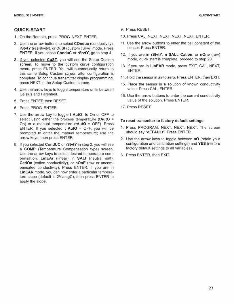
QUICK-START
1. On the Remote, press PROG, NEXT, ENTER.
2. Use the arrow buttons to select COnduc (conductivity),
rStvtY (resistivity), or CuSt (custom curve) mode. Press
ENTER. If you chose ConduC or rStvtY, go to step 4.
3. If you selected CuST, you will see the Setup Custom
screen. To move to the custom curve configuration
menu, press ENTER. You will automatically return to
this same Setup Custom screen after configuration is
complete. To continue transmitter display programming,
press NEXT in the Setup Custom screen.
4. Use the arrow keys to toggle temperature units between
Celsius and Farenheit.
5. Press ENTER then RESET.
6. Press PROG, ENTER.
7. Use the arrow key to toggle t AutO to On or OFF to
select using either the process temperature (tAutO =
On) or a manual temperature (tAutO = OFF). Press
ENTER. If you selected t AutO = OFF, you will be
prompted to enter the manual temperature; use the
arrow keys, then press ENTER.
8. If you selected CondUC or rStvtY in step 2, you will see
a COMP (Temperature Compensation type) screen.
Use the arrow keys to select desired temperature com-
pensation: LinEAr (linear), n SALt (neutral salt),
CatIOn (cation conductivity), or nOnE (raw or uncom-
pensated conductivity). Press ENTER. If you are in
LinEAR mode, you can now enter a particular tempera-
ture slope (default is 2%/degC), then press ENTER to
apply the slope.
9. Press RESET.
10. Press CAL, NEXT, NEXT, NEXT, NEXT, ENTER.
11. Use the arrow buttons to enter the cell constant of the
sensor. Press ENTER.
12. If you are in rStvtY, n SALt, Cation, or nOne (raw)
mode, quick start is complete, proceed to step 20.
13. If you are in LinEAR mode, press EXIT, CAL, NEXT,
ENTER.
14. Hold the sensor in air to zero. Press ENTER, then EXIT.
15. Place the sensor in a solution of known conductivity
value. Press CAL, ENTER.
16. Use the arrow buttons to enter the current conductivity
value of the solution. Press ENTER.
17. Press RESET.
To reset transmiter to factory default settings:
1. Press PROGRAM, NEXT, NEXT, NEXT. The screen
should say "dEFAULt". Press ENTER.
2. Use the arrow keys to toggle between nO (retain your
configuration and calibration settings) and YES (restore
factory default settings to all variables).
3. Press ENTER, then EXIT.
MODEL 5081-C-FF/FI QUICK-START
Credit Cards for U.S. Purchases Only.
The right people,the right answers,right now. ON-LINE ORDERING NOW AVAILABLE ON OUR WEB SITE