Foundry FastIron X Series Chassis Hardware Installation Guide FastIron SuperX FastIron SX 800 FastIron SX 1600 FSX Release 03.2.00 4980 Great America Parkway Santa Clara, CA 95054 Tel 408.207.1700 March 2007 ™
Transcript
Foundry FastIron X Series ChassisHardware Installation Guide
No part of this work may be reproduced in any form or by any means – graphic, electronic or mechanical, including photocopying, recording, taping or storage in an information retrieval system – without prior written permission of the copyright owner.
The trademarks, logos and service marks ("Marks") displayed herein are the property of Foundry or other third parties. You are not permitted to use these Marks without the prior written consent of Foundry or such appropriate third party.
Foundry Networks, BigIron, FastIron, IronView, JetCore, NetIron, ServerIron, TurboIron, IronWare, EdgeIron, IronPoint, the Iron family of marks and the Foundry Logo are trademarks or registered trademarks of Foundry Networks, Inc. in the United States and other countries.
F-Secure is a trademark of F-Secure Corporation. All other trademarks mentioned in this document are the property of their respective owners.
Contents
CHAPTER 1ABOUT THIS GUIDE..................................................................................... 1-1INTRODUCTION ...........................................................................................................................................1-1WHAT’S INCLUDED IN THIS EDITION? ...........................................................................................................1-1AUDIENCE ..................................................................................................................................................1-1NOMENCLATURE .........................................................................................................................................1-2RELATED PUBLICATIONS .............................................................................................................................1-2HOW TO GET HELP .....................................................................................................................................1-2
WEB ACCESS .......................................................................................................................................1-2EMAIL ACCESS .....................................................................................................................................1-2TELEPHONE ACCESS ............................................................................................................................1-2
HARDWARE BENEFITS ..........................................................................................................................2-1POE PORT DENSITY ............................................................................................................................2-2SUPPORTED CONFIGURATIONS .............................................................................................................2-2
SOFTWARE FEATURES ................................................................................................................................2-3POE APPLICATIONS ....................................................................................................................................2-3HARDWARE FEATURES ...............................................................................................................................2-3
FastIron Hardware Installation Guide for the FSX, FSX 800, and FSX 1600
POWER SUPPLIES ..............................................................................................................................2-21COOLING SYSTEM ..............................................................................................................................2-26BUILT-IN MOUNTING BRACKETS ..........................................................................................................2-26
CHAPTER 3INSTALLING THE CHASSIS ........................................................................... 3-1SUMMARY OF INSTALLATION TASKS .............................................................................................................3-2UNPACKING A SYSTEM ................................................................................................................................3-3INSTALLATION PRECAUTIONS .......................................................................................................................3-3
GENERAL PRECAUTIONS .......................................................................................................................3-3LIFTING PRECAUTIONS .........................................................................................................................3-3POWER PRECAUTIONS AND WARNINGS .................................................................................................3-4
PREPARING THE INSTALLATION SITE ............................................................................................................3-5CABLING INFRASTRUCTURE ..................................................................................................................3-5INSTALLATION LOCATION ......................................................................................................................3-5
REMOVING EXTRA SHIPMENT SCREWS (FSX AND FSX 800 ONLY) ...............................................................3-5INSTALLING A CHASSIS IN A RACK ...............................................................................................................3-6
INSTALLING MOUNTING BRACKETS ON THE FSX 1600 CHASSIS .............................................................3-7REMOVING THE SLOT PANELS .....................................................................................................................3-8INSTALLING THE MANAGEMENT AND INTERFACE MODULES ...........................................................................3-8ATTACHING A MANAGEMENT STATION .......................................................................................................3-12
ATTACHING A PC OR TERMINAL TO THE CONSOLE PORT OR 10/100/1000 COPPER PORT ....................3-12ATTACHING A SWITCH TO AN ETHERNET PORT ....................................................................................3-12
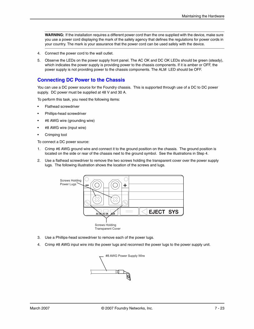
POWERING ON THE SYSTEM .....................................................................................................................3-13CONNECTING AC POWER TO THE CHASSIS .........................................................................................3-13CONNECTING DC POWER TO THE CHASSIS .........................................................................................3-15
VERIFYING PROPER OPERATION ...............................................................................................................3-17OBSERVING THE LEDS .......................................................................................................................3-17DISPLAYING THE MODULE STATUS ......................................................................................................3-19
RECOVERING FROM A LOST PASSWORD ................................................................................................4-2CONFIGURING IP ADDRESSES .....................................................................................................................4-3
CONNECTING NETWORK DEVICES ...............................................................................................................4-4CABLE SPECIFICATIONS ........................................................................................................................4-4CONNECTING TO ETHERNET OR FAST ETHERNET HUBS .........................................................................4-5CONNECTING TO WORKSTATIONS, SERVERS, OR ROUTERS ...................................................................4-5CONNECTING A NETWORK DEVICE TO A FIBER PORT ON THE FOUNDRY DEVICE .....................................4-6AUTOMATIC MDI/MDIX DETECTION ......................................................................................................4-7
TESTING NETWORK CONNECTIVITY ..............................................................................................................4-7PINGING AN IP ADDRESS ......................................................................................................................4-7OBSERVING LEDS ................................................................................................................................4-7TRACING A ROUTE ...............................................................................................................................4-8
TROUBLESHOOTING NETWORK CONNECTIONS .............................................................................................4-9USING VIRTUAL CABLE TESTING TO DIAGNOSE A CABLE .......................................................................4-9
CHAPTER 5MANAGING THE CHASSIS AND MODULES ..................................................... 5-1DISPLAYING CHASSIS STATUS AND TEMPERATURE READINGS ......................................................................5-1MANAGING THE COOLING SYSTEM ..............................................................................................................5-9
CONFIGURING THE COOLING SYSTEM ...................................................................................................5-9MONITORING THE COOLING SYSTEM ...................................................................................................5-19
DISPLAYING THE SYSLOG CONFIGURATION AND STATIC AND DYNAMIC BUFFERS .........................................5-22MANAGING THE SWITCH FABRIC MODULES (FSX 800 AND FSX 1600 ONLY) .............................................5-23DISPLAYING MANAGEMENT MODULE CPU USAGE .....................................................................................5-24REMOVING MAC ADDRESS ENTRIES .........................................................................................................5-24
CHAPTER 6USING A REDUNDANT MANAGEMENT MODULE............................................. 6-1HOW MANAGEMENT MODULE REDUNDANCY WORKS ....................................................................................6-1
MANAGEMENT MODULE REDUNDANCY CONFIGURATION ...............................................................................6-3CHANGING THE DEFAULT ACTIVE CHASSIS SLOT ...................................................................................6-3
MANAGING MANAGEMENT MODULE REDUNDANCY .......................................................................................6-4FILE SYNCHRONIZATION BETWEEN THE ACTIVE AND STANDBY MANAGEMENT MODULES .........................6-4MANUALLY SWITCHING OVER TO THE STANDBY MANAGEMENT MODULE ................................................6-5REBOOTING THE ACTIVE AND STANDBY MANAGEMENT MODULES ..........................................................6-6
MONITORING MANAGEMENT MODULE REDUNDANCY ....................................................................................6-6DETERMINING MANAGEMENT MODULE STATUS .....................................................................................6-6DISPLAYING TEMPERATURE INFORMATION .............................................................................................6-9DISPLAYING SWITCHOVER INFORMATION ...............................................................................................6-9
CHAPTER 7MAINTAINING THE HARDWARE..................................................................... 7-1HARDWARE MAINTENANCE SCHEDULE .........................................................................................................7-1CLEANING THE FIBER-OPTIC CONNECTORS .................................................................................................7-2REPLACING A MANAGEMENT MODULE .........................................................................................................7-2
INSTALLATION PRECAUTIONS ................................................................................................................7-2INSTALLING A NEW MANAGEMENT MODULE ...........................................................................................7-3
REPLACING A SWITCH FABRIC MODULE (FSX 800 AND FSX 1600 ONLY) ....................................................7-5REMOVING A SWITCH FABRIC MODULE .................................................................................................7-5INSTALLING A NEW SWITCH FABRIC MODULE ........................................................................................7-6
FastIron Hardware Installation Guide for the FSX, FSX 800, and FSX 1600
REPLACING AN INTERFACE MODULE ............................................................................................................7-8PRECAUTIONS ......................................................................................................................................7-8BEFORE REMOVING AN INTERFACE MODULE .........................................................................................7-8REMOVING AN INTERFACE MODULE .......................................................................................................7-9INSTALLING A NEW INTERFACE MODULE ................................................................................................7-9CONFIGURING A LAN/WAN PHY INTERFACE MODULE .........................................................................7-11DISABLING AND RE-ENABLING AN INTERFACE MODULE ........................................................................7-12
INSTALLING OR REPLACING A POE DAUGHTER CARD ................................................................................7-12REPLACING A COPPER OR FIBER OPTIC MODULE ......................................................................................7-16
REMOVING A COPPER OR FIBER OPTIC MODULE .................................................................................7-16INSTALLING A NEW COPPER OR FIBER OPTIC MODULE ........................................................................7-17CABLING A FIBER OPTIC MODULE .......................................................................................................7-17
INSTALLING OR REPLACING A POWER SUPPLY ...........................................................................................7-17DETERMINING WHICH POWER SUPPLY FAILED ....................................................................................7-18REMOVING AN AC POWER SUPPLY .....................................................................................................7-18REMOVING A DC POWER SUPPLY .......................................................................................................7-19INSTALLING A NEW POWER SUPPLY ....................................................................................................7-21CONNECTING AC POWER TO THE CHASSIS .........................................................................................7-21CONNECTING DC POWER TO THE CHASSIS .........................................................................................7-23VERIFYING PROPER OPERATION .........................................................................................................7-25DISPLAYING THE STATUS OF THE POWER SUPPLIES ............................................................................7-26
REPLACING THE FSX AND FSX 800 FAN TRAY .........................................................................................7-26REPLACING THE FSX 1600 FAN ASSEMBLIES ............................................................................................7-28
IntroductionThis guide describes the FastIron SuperX® (FSX), FastIron SX 800® (FSX 800), and FastIron SX 1600® (FSX 1600) Layer 2/Layer 3 switches from Foundry Networks.
NOTE: The FSX, FSX 800, and FSX 1600 are collectively referred to throughout this manual as the FastIron X Series chassis devices.
This guide includes procedures for installing the hardware and configuring essential parameters such as permanent passwords and IP addresses. The basic software configuration procedures show how to perform tasks using the CLI. This guide also includes instructions for managing and maintaining the hardware.
This guide applies to the FastIron X Series chassis devices.
What’s Included in This Edition?This edition includes the following releases:
• 03.2.00
Enhanced Hot Swap is introduced in FSX software release 03.2.00. Beginning with this release, issuing the disable module command before removing the module is no longer required on the FastIron SX 800 and FastIron SX 1600 chassis. This is referred to as “Enhanced Hot Swap”. See “Hot Swap Support” on page 2-15.
• 03.0.00
• 02.2.01
• 02.2.00
• 02.1.00
• 02.0.01
AudienceThis guide is designed for network installers, system administrators, and resellers who will install the hardware. This guide assumes a working knowledge of Layer 2 and Layer 3 switching and routing concepts.
FastIron Hardware Installation Guide for the FSX, FSX 800, and FSX 1600
NomenclatureThis guide uses the following typographical conventions to show information:
Italic highlights the title of another publication and occasionally emphasizes a word or phrase.
Bold highlights a CLI command.
Bold Italic highlights a term that is being defined.
NOTE: A note emphasizes an important fact or calls your attention to a dependency.
WARNING: A warning calls your attention to a possible hazard that can cause injury or death.
CAUTION: A caution calls your attention to a possible hazard that can damage equipment.
Related PublicationsThe following Foundry Networks documents supplement the information in this guide.
• Foundry FastIron Configuration Guide – for the FastIron X Series chassis and FastIron compact devices, provides basic configuration procedures for system-level features, and provides configuration information for enterprise routing protocols including IP, RIP, IP multicast, OSPF, BGP4, VRRP and VRRPE. This guide also provides procedures for securing management access to Foundry devices and for protecting against Denial of Service (DoS) attacks.
• Foundry FastIron Compact Switch Hardware Installation Guide – provides hardware installation procedures for the FastIron compact switches (FES, FESX, and FWSX).
• Foundry Management Information Base Reference – contains the Simple Network Management Protocol (SNMP) Management Information Base (MIB) objects supported on Foundry devices.
NOTE: For the latest edition of this document, which contains the most up-to-date information, see Product Manuals at kp.foundrynet.com.
How to Get HelpFoundry Networks technical support will ensure that the fast and easy access that you have come to expect from your Foundry Networks products will be maintained.
Web Access• https://kp.foundrynet.com
Email AccessTechnical requests can also be sent to the following email address:
This chapter contains an overview of the following FastIron X Series® Layer 2 / Layer 3 switches:
• FastIron SuperX (FSX)
• FastIron SX 800 (FSX 800)
• FastIron SX 1600 (FSX 1600)
This chapter includes the following topics:
• “Product Overview” on page 2-1
• “Software Features” on page 2-3
• “POE Applications” on page 2-3
• “Hardware Features” on page 2-3
Product OverviewDesigned for medium to large enterprise backbones, the FastIron X Series chassis devices are modular switches that provide the enterprise network with a complete end-to-end Enterprise LAN solution, ranging from the wiring closet to the LAN backbone.
Hardware BenefitsThe FastIron X Series chassis devices provide the following benefits:
• The FSX management module is non-blocking, with a built-in switch fabric module and twelve combination Gigabit Ethernet copper or fiber ports that provide connectivity to your existing management network.
• The FSX 800 and FSX 1600 management modules have a console port and a 10/100/1000 port that provide connectivity to your existing management network. The management modules optionally support 2-port 10-GbE ports.
• The FSX 800 and FSX 1600 management modules are interchangeable between devices.
• Optional dual management modules on the FSX 800 and FSX 1600 provide 100% redundancy.
• The crossbar (xbar) architecture enables the management module to switch 30 Gigabits per second between each interface module and within the management module.
• The interface modules and power supplies are interchangeable among all FastIron X Series chassis devices.
• The interface modules are hot swappable, which means you can remove and replace them while the chassis is powered on and running. (See “Replacing an Interface Module” on page 7-8 for details on hot swapping an
FastIron Hardware Installation Guide for the FSX, FSX 800, and FSX 1600
interface module.)
• The FSX 800 and FSX 1600 management, switch fabric, and interface modules are hot swappable, which means you can remove and replace them while the chassis is powered on and running.
• Completely separate data and control planes, which results in uncompromised switching performance, increased reliability of both planes, and increased security of the control plane in the event of a Denial of Service (DoS) attack on the data plane.
• Distributed data and control planes, which results in uncompromised wire-speed performance for the data plane and faster and more efficient performance of management functions for the control plane.
POE Port DensityTable 2.1 shows the maximum POE port density for the FastIron X Series chassis devices.
Supported ConfigurationsPremium FastIron X Series chassis devices support Layer 2 switching and full Layer 3 multiprotocol routing. Standard devices support Layer 2 and base Layer 3 switching. All standard FastIron X Series chassis devices can be upgraded to full Layer 3 multiprotocol routing, at which time they are considered to be premium devices.
All FastIron X Series chassis devices optionally support Power over Ethernet (POE), providing the means for integrating data, voice, and video over existing Ethernet cables.
Table 2.2 lists the configurations supported on the FastIron X Series chassis devices.
Table 2.1: Maximum Number of POE Class 3 (15.4W) Ports per Power Supply
Power Supply Number of Power Supplies
FSX FSX 800 FSX 1600
SX-ACPWR-POE 1 70 70 70
SX-ACPWR-POE 2 140 140 140
SX-ACPWR-POE 3 N/A N/A 210
SX-ACPWR-POE 4 N/A N/A 280
SX-ACPWR2500-POE 1 140 140 140
SX-ACPWR2500-POE 2 2801
1.The FSX and FSX 800 support a maximum of 192 POE ports. The FSX 1600 supports a maximum of 384 POE ports.
2801 280
SX-ACPWR2500-POE 3 N/A N/A 4201
SX-ACPWR2500-POE 4 N/A N/A 5601
Table 2.2: FastIron Product Family Support Configurations
Software FeaturesSoftware features differ depending on the software version that is loaded on the device. When first shipped, Standard and POE devices support Layer 2 and base Layer 3 switching. Premium (PREM) devices support Layer 2 switching and full Layer 3 multiprotocol routing. All FastIron X Series chassis devices can be upgraded to premium models, meaning all models can support full Layer 3 multiprotocol routing.
See the Foundry FastIron Configuration Guide and the release notes for a complete list of software features supported on your device.
POE ApplicationsFoundry’s FastIron X Series chassis devices with POE provides Power over Ethernet, compliant with the standards described in the IEEE 802.3af specification for delivering in-line power. The 802.3af specification defines the standard for delivering power over existing network cabling infrastructure, enabling multicast-enabled full streaming audio and video applications for converged services, such as, Voice over IP (VoIP), WLAN access points, IP surveillance cameras, and other IP technology devices.
POE technology eliminates the need for an electrical outlet and dedicated UPS near IP powered devices. With power sourcing devices, such as Foundry’s FastIron X Series chassis devices with POE, power is consolidated and centralized in the wiring closets, improving the reliability and resiliency of the network. Because POE can provide power over Ethernet cable, power is continuous, even in the event of a power failure.
For more information about POE and how to configure it, see the Foundry FastIron Configuration Guide.
Hardware FeaturesThe FastIron X Series chassis devices are composed of the following major hardware components:
• Chassis
• Management module
• The FSX management module has a built-in switch fabric module.
• The FSX 800 and FSX 1600 optionally support dual management modules which provide 100% redundancy.
• Separate switch fabric modules (FSX 800 and FSX 1600 only)
• Interface modules
• Power supplies
• The fan tray in the FSX and FSX 800 is composed of six five-speed fans and a fan control module.
• The FSX 1600 has an air filter in the bottom front of the chassis and two fan trays at the rear of the chassis.
• Built-in mounting brackets
The following sections provide more information about these components.
For details about physical dimensions, power supply specifications, and pinouts, see the chapter “Hardware Specifications” on page 8-1.
FSX 1600 X X X
Table 2.2: FastIron Product Family Support Configurations
FastIron Hardware Installation Guide for the FSX, FSX 800, and FSX 1600
FSX ChassisThe FSX chassis is 6 rack units (RUs) in height and consists of the following:
• One full slot for the management module
• Eight half slots for the interface modules
• Four slots for power supplies along the bottom of the card shelf. The power supply slots add an additional RU to the height of the chassis.
Figure 2.1 shows the FSX chassis.
Figure 2.1 FSX Chassis
Upon shipment from the factory, the following components are installed in the FSX chassis:
• A slot panel in each interface module slot and power supply slot that does not currently have a module or power supply installed in it. The slot panel ensures proper airflow within the chassis.
• One or two AC or DC power supplies
• A fan tray assembly which contains the cooling system for the chassis
In the FSX slots, you can install the following:
• One management module
• Up to eight interface modules
• Up to four AC and DC power supplies: two system (12-volt) power supplies and two POE (48- or 220-volt) power supplies
Before installing any modules or power supplies, you must remove the slot panel.
CAUTION: If you do not install a module in a slot, you must keep the slot panel in place. If you run the chassis with an uncovered slot, the system will overheat.
Figure 2.2 shows the FSX Chassis and the slots into which you can install the various modules and power supplies.
DC OK ALMAC OK DC OK ALMAC OK DC OK ALMAC OK DC OK ALMAC OK
Figure 2.2 also shows an electrostatic discharge (ESD) connector, into which you can plug an ESD wrist strap to ground yourself while handling and installing modules.
WARNING: For safety reasons, the ESD wrist strap should contain a series 1 meg ohm resistor.
FSX 800 ChassisThe FSX 800 chassis is 6 rack units in height and consists of the following:
• Two half slots for the management modules
• Two half slots for the switch fabric modules
• Eight half slots for the interface modules
• Four slots for power supplies along the bottom of the card shelf. The power supply slots add an additional rack unit (RU) to the height of the chassis.
FastIron Hardware Installation Guide for the FSX, FSX 800, and FSX 1600
The FSX 800 chassis ships from the factory with the following components installed:
• Two switch fabric modules
• A slot panel in each interface module slot and power supply slot that does not currently have a module or power supply installed in it. The slot panel ensures proper airflow within the chassis.
• One AC power supply
• A fan tray assembly which contains the cooling system for the chassis
In the FSX 800 slots, you can install the following:
• Up to two management modules
• Up to eight interface modules
• Up to four AC and DC power supplies: two system (12-volt) power supplies and two POE (48- or 220-volt) power supplies
Before installing any modules or power supplies, you must remove the slot panel.
CAUTION: If you do not install a module in a slot, you must keep the slot panel in place. If you run the chassis with an uncovered slot, the system will overheat.
Figure 2.4 shows the FSX 800 Chassis and the slots into which you can install the various modules and power supplies.
Figure 2.4 FSX 800 Chassis Slots
Figure 2.4 also shows an electrostatic discharge (ESD) connector, into which you can plug an ESD wrist strap to ground yourself while handling and installing modules.
WARNING: For safety reasons, the ESD wrist strap should contain a series 1 meg ohm resistor.
Slot 1 Slot 2 Fan Tray
Slot 3 Slot 4
Slot 5 Slot 6
Slot 8Slot 7
Slot 10
ESD Connector
SwitchFabricSlot 2
Slot 9
SwitchFabricSlot 1
AC OK DC OK ALM EJECT SYS AC OK DC OK ALM EJECT SYSAC OK DC OK ALM EJECT POE AC OK DC OK ALM EJECT POE
FSX 1600 ChassisThe FSX 1600 chassis is 14 rack units in height and consists of the following:
• Two half slots for the management modules
• Two half slots for the switch fabric modules
• Sixteen half slots for the interface modules
• Eight slots for power supplies along the bottom of the card shelf.
Figure 2.5 shows the FSX 1600 chassis.
Figure 2.5 FSX 1600 Chassis
Upon shipment from the factory, the following components are installed in the FSX 1600 chassis:
• Two switch fabric modules
• A slot panel in each interface module slot and power supply slot that does not currently have a module or power supply installed in it. The slot panel ensures proper airflow within the chassis.
• Two AC power supplies
• A fan tray assembly which contains the cooling system for the chassis
In the FSX 1600 slots, you can install the following:
• Up to two management modules
• Up to 16 interface modules
• Up to eight AC or DC power supplies (four system (SYS) power supplies and four POE power supplies)
Before installing any modules or power supplies, you must remove the slot panel.
FastIron Hardware Installation Guide for the FSX, FSX 800, and FSX 1600
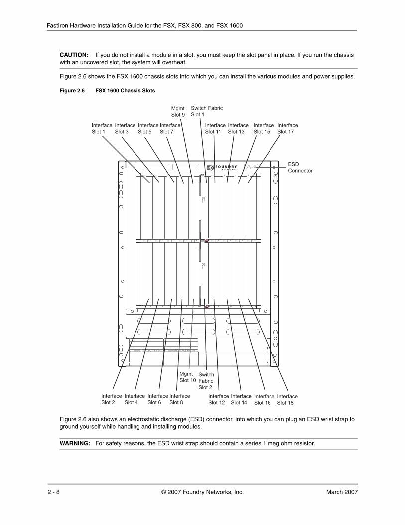
CAUTION: If you do not install a module in a slot, you must keep the slot panel in place. If you run the chassis with an uncovered slot, the system will overheat.
Figure 2.6 shows the FSX 1600 chassis slots into which you can install the various modules and power supplies.
Figure 2.6 FSX 1600 Chassis Slots
Figure 2.6 also shows an electrostatic discharge (ESD) connector, into which you can plug an ESD wrist strap to ground yourself while handling and installing modules.
WARNING: For safety reasons, the ESD wrist strap should contain a series 1 meg ohm resistor.
AC OK DC OK ALM EJECT SYS AC OK DC OK ALM EJECT SYS
Management ModulesThis section describes the management modules for the FastIron X Series chassis devices.
• The FSX chassis requires one management module. The management module occupies one full slot.
• The FSX 800 and FSX 1600 chassis each require one management module and optionally support two management modules for 100% redundancy. Each management module occupies one half slot.
FSX Management Modules
The FSX management module has a built-in switch fabric module and comes with 12 combination Gigabit Ethernet Copper and Fiber ports.
NOTE: The FSX management module is dedicated, which means that it can be installed in the FSX chassis only. If you attempt to install the FSX management module in the FSX 800, FSX 1600, or other Foundry chassis, the chassis and module will not function properly.
Table 2.3 lists the management modules supported on the FSX chassis.
The FSX management module does the following:
• Controls the FSX hardware components
• Houses and controls the switch fabric module
• Runs the networking protocols
• Provides the real time operating system
The management module is located in slot 9, just above the power supply slots (see Figure 2.2).
Figure 2.7 shows the management module’s front panel.
Figure 2.7 FSX Management Module Front Panel
The front panel includes the following control features:
• A Console port
• 12 combination Gigabit Ethernet Copper and Fiber ports
• 25 LEDs – One LED for power, 12 LEDs for the copper ports, and 12 LEDs for the fiber ports
• A recessed reset button
Table 2.3: FSX Management Modules
Description Part Number Microprocessor Speed (MHz)
MB SDRAM
Management 1 (M-1) Module SX-FI12GM-4 400 256
Management 2 (M-2) Module1
1.Available starting with FSX release 02.2.00, the M2 Management Module enables support for larger routing tables (1,000,000 BGP routes) with the full Layer 3 code.
FastIron Hardware Installation Guide for the FSX, FSX 800, and FSX 1600
Gigabit Ethernet Ports on the FSX Management ModuleThe FSX management module’s front panel includes 12 combination copper and fiber Gigabit Ethernet ports.
• RJ-45 copper interfaces for 1000Base-T, Cat5 copper cabling – The copper ports support automatic MDI/MDIX detection, and use auto-sensing and auto-negotiating to determine the speed (10, 100, or 1000 Mbps) and duplex mode (full-duplex or half-duplex) of the port at the other end of the link, and adjust the port accordingly. Note that ports operating at 1000 Mbps operate in the full-duplex mode only and cannot be modified.
• Mini-GBIC slots for the types of fiber cabling listed in Table 8.7 on page 8-10.
NOTE: The Management Module does not support copper mini-GBICs. These are supported on the 24-port Fiber module only.
NOTE: Some older SFP modules (mini-GBICs for Gigabit Ethernet ports) have latching mechanisms which are larger than the newer parts. These latches could interfere with one another when inserted side by side into a module. Avoid using these mini-GBICs side by side in the same module. These older modules are identified by the number PL-XPL-00-S13-22 or PL-XPL-00-L13-23 above the Serial Number. All newer mini-GBICs do not have this limitation.
The Gigabit Ethernet fiber ports operate at a fixed speed of 1000 Mbps (they do not support 10 Mbps or 100 Mbps connections), and use auto-negotiation to automatically configure the highest performance mode of inter-operation with the connected device.
One port out of each pair of copper and fiber ports can be active at a time. For example, you can use either copper port 2 or fiber port 2, but not both at the same time. You can use a combination of fiber and copper ports or all copper or all fiber ports, as needed.
If you attach both the copper and fiber connectors for a port to the network, the fiber connector takes precedence over the copper connector. These ports support true media automatic detection, meaning the device selects the fiber or copper connector based on link availability. If a fiber link cannot be established, the device selects the copper media.
Typical uses of these ports include but are not limited to the following:
• Connecting a PC through which you can access the system directly or through a Telnet connection and configure, monitor, and manage the FSX system.
• Connecting a Gigabit Ethernet switch, which will provide connectivity to your existing management network. You can then access the FSX system and configure, monitor, and manage the system from a management station.
NOTE: The existing management networks into which you can connect the Gigabit Ethernet ports must be separate and isolated from the network over which user packets are switched and routed as shown in Figure 2.8.
Figure 2.8 Separate Management and Switching/Routing Networks
ManagementNetwork
Switching and RoutingNetwork
Managementport
Interfacemodule port
FastIron SuperX
DC OK ALMAC OK DC OK ALMAC OK DC OK ALMAC OK DC OK ALMAC OK
LEDs on the FSX Management ModuleThe FSX management module provides status information using the LEDs listed in Table 2.4. The location of the LEDs is as follows:
• The fiber connectors use the LEDs located beneath the mini-GBIC slots.
• The copper connectors use square LEDs located in the upper right and left corners of the upper Gigabit copper connectors. The LED on the left side is for the upper copper connector. The LED on the right side is for the lower copper connector.
Table 2.4 describes the LEDs on the FSX management module.
Built-in Switch Fabric ModuleThe switch fabric module switches user packets from one interface module installed in the chassis to another. On the FSX, the switch fabric module is built into the Management module.
Console PortThe Console port on the management module is a standard DB-9 serial connector through which you can attach a PC or terminal to configure the system using the command line interface (CLI).
The Console port interfaces the control plane only and not the data plane.
Reset ButtonThe reset button on the management module allows you to restart the system. The reset button is recessed to prevent it from being pushed accidentally.
The reset button is located next to the console port on the management module.
Table 2.4: FSX Management Module LEDs
LED Description and Position State Meaning
Pwr Round LED located to the left of the console port
On (Green) The module is receiving power.
Off The module is not receiving power.
10/100/1000 Mbps Copper Ports (
Square LED located on upper left corner of upper copper connector for upper copper connector
Square LED located on upper right corner of upper copper connector for lower copper connector
On (Green) A link is established with the remote port.
Blinking The port is transmitting and receiving traffic.
Off A link is not established with the remote port.
1000 Mbps Fiber Ports
Round LED located beneath the fiber connectors
On (Green) A link is established with the remote port.
Blinking The port is transmitting and receiving packets.
Off A link is not established with the remote port.
FastIron Hardware Installation Guide for the FSX, FSX 800, and FSX 1600
FSX 800 and FSX 1600 Management Modules
The management modules for the FSX 800 and FSX 1600 are interchangeable between devices. The management modules have either two 10-GbE uplink ports or have no ports. Standard management modules provide Layer 2 and base Layer 3 functionality only. Premium management modules support full Layer 3 functionality.
NOTE: The management modules are dedicated, which means that you must install them in the appropriate chassis. If you attempt to install the FSX management module in the FSX 800, FSX 1600, or other Foundry chassis, the chassis and module will not function properly. Likewise, if you try to install the FSX 800 or FSX 1600 management module in the FSX or other Foundry chassis, the chassis and module will not function properly.
NOTE: You cannot intermix M-3 and M-4 management modules in the FSX 800 and FSX 1600 chassis devices.
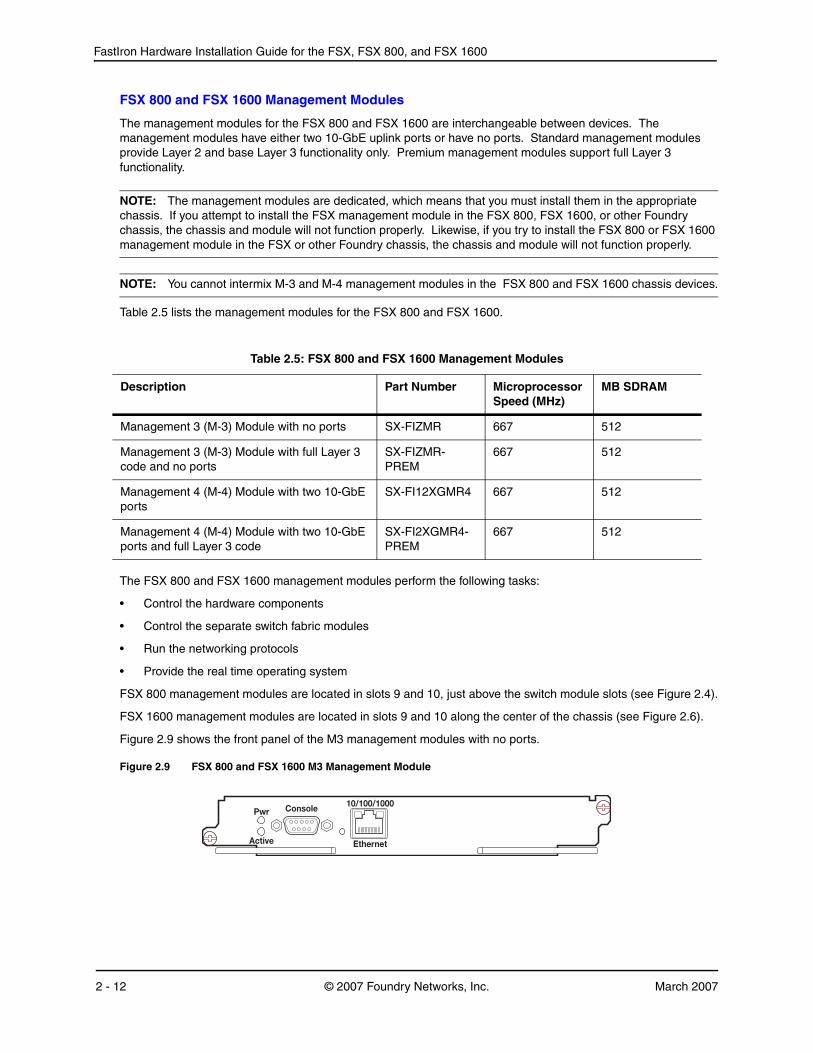
Table 2.5 lists the management modules for the FSX 800 and FSX 1600.
The FSX 800 and FSX 1600 management modules perform the following tasks:
• Control the hardware components
• Control the separate switch fabric modules
• Run the networking protocols
• Provide the real time operating system
FSX 800 management modules are located in slots 9 and 10, just above the switch module slots (see Figure 2.4).
FSX 1600 management modules are located in slots 9 and 10 along the center of the chassis (see Figure 2.6).
Figure 2.9 shows the front panel of the M3 management modules with no ports.
Figure 2.9 FSX 800 and FSX 1600 M3 Management Module
Table 2.5: FSX 800 and FSX 1600 Management Modules
Description Part Number Microprocessor Speed (MHz)
MB SDRAM
Management 3 (M-3) Module with no ports SX-FIZMR 667 512
Management 3 (M-3) Module with full Layer 3 code and no ports
SX-FIZMR-PREM
667 512
Management 4 (M-4) Module with two 10-GbE ports
SX-FI12XGMR4 667 512
Management 4 (M-4) Module with two 10-GbE ports and full Layer 3 code
Figure 2.10 shows the front panel of the M4 management modules with two 10-GbE ports.
Figure 2.10 FSX 800 and FSX 1600 M4 Management Module
The front panel on the M3 and M4 management modules include the following control features:
• A Console port and 10/100/1000 RJ-45 copper port allow you to access the system’s CLI directly from a PC or terminal or via a Telnet connection to the PC or terminal.
• No 10-GbE fiber ports or two 10-GbE fiber ports
• LEDs for power and active/standby status
• Four LEDs for the two 10-GbE fiber ports (2-port 10-GbE modules only)
• A recessed reset button
10/100/1000 Ethernet Port on the FSX 800 and FSX 1600 Management ModulesThe 10/100/1000 RJ-45 copper port on the management module enables you to attach a PC or terminal. From this Ethernet port, you can access the system’s CLI or Web management interface directly from the PC or terminal or via a Telnet connection to the PC or terminal.
10-Gigabit Ethernet Ports on the FSX 800 and FSX 1600 Management ModulesThe FSX 800 and FSX 1600 management modules optionally come with two 10-GbE fiber ports through which you can connect your device to other network devices at a speed of 10 Gigabits per second.
The 10-GbE ports have optical interfaces with LC connectors for 10-Gigabit Small Form Factor Pluggable (XFP) MSA-compliant transceivers. The transceivers support the fiber optic cabling for LAN PHY listed in Table 8.7 on page 8-10.
LEDs on the FSX 800 and FSX 1600 Management ModulesThe management modules provide status information using the LEDs listed in Table 2.6.
Table 2.6: FSX 800 and FSX 1600 Management Module LEDs
LED Description and Position State Meaning
Pwr Round LED located to the left of the console port
On (Green) The module is receiving power.
Off The module is not receiving power.
Active Round LED located to the left of the console port
On (Green) The module is the active management module.
Off The module is not the active management module.
10/100/1000 Port LEDs
Lnk Left-most LED above the port On The port is connected.
FastIron Hardware Installation Guide for the FSX, FSX 800, and FSX 1600
Console Port
The Console port on the management module is a standard DB-9 serial connector through which you can attach a PC or terminal to configure the system using the command line interface (CLI).
The Console port interfaces the control plane only and not the data plane.
Reset ButtonThe reset button on the management module allows you to restart the system. The reset button is recessed to prevent it from being pushed accidentally.
The reset button is located next to the console port on the management module.
Switch Fabric Modules (FSX 800 and FSX 1600 only)The switch fabric modules switch user packets from one interface module installed in the chassis to another.
The FSX 800 and FSX 1600 each require two switch fabric modules. Unlike the FSX, which has a switch fabric module built into the management module, the switch fabric modules in the FSX 800 and FSX 1600 chassis are separate from the management modules and are physically located next to the management modules.
Figure 2.11 shows the FSX 800 and FSX 1600 switch fabric module.
Figure 2.11 FSX 800 and FSX 1600 Switch Fabric Module
Act Right-most LED above the port.
On or Blinking The port is transmitting and receiving traffic.
Off The port is not transmitting or receiving traffic.
10-GbE Port LEDs
Lnk Top-most LED to the left of the port.
On Fiber port is connected.
Off No fiber port connection exists.
Act Bottom-most LED to the left of the port.
On or Blinking The port is transmitting and receiving traffic.
Off The port is not transmitting or receiving traffic.
The front panel provides status information using the LEDs listed in Table 2.7.
Interface ModulesThis section describes the Interface modules for the FastIron X Series chassis devices. All interface modules are interchangeable among all FastIron X Series chassis devices.
• In the FSX chassis, you can install up to eight interface modules in the slots shown in Figure 2.2 on page 2-5.
• In the FSX 800 chassis, you can install up to eight interface modules in the slots shown in Figure 2.4 on page 2-6.
• In the FSX 1600 chassis, you can install up to 16 interface modules in the slots shown in Figure 2.6 on page 2-8.
You can install a combination of the following types of interface modules:
Hot Swap Support
• Starting with software release 02.2.01 for the FSX, the interface modules are hot swappable, which means you can remove and replace them without powering down the system; however, you must issue the disable module command before you remove the modules from the chassis.
• Prior to software release 03.2.00, all FSX 800 and FSX 1600 software releases support hot swap of the interface modules, but the disable module command must be issued, before removing the modules from the
Table 2.7: Switch Fabric Module LEDs
LED Description and Position State Meaning
Pwr Top-most LED On (Green) The module is receiving power.
Off The module is not receiving power.
Active Bottom-most LED On (Green) The module is functioning properly.
Off The module is not functioning properly.
Table 2.8: Interface Modules
Interface Module1
1.These interface modules are interchangeable among all FastIron X Series chassis devices.
Part Number FSX FSX 800 FSX 1600
24-port Gigabit Ethernet Fiber (1000 Mbps only)
SX-FI424F 02.1.00 and later
X X
24-port Gigabit Ethernet copper without POE
SX-FI424C 02.2.00 and later
X X
24-port Gigabit Ethernet copper with POE SX-FI424P 02.2.00 and later
X X
24-port 100/1000 Fiber SX-FI424HF 02.4.00 and later
X X
2-port 10-Gigabit Ethernet LAN module SX-FI42XG X X X
FastIron Hardware Installation Guide for the FSX, FSX 800, and FSX 1600
chassis.
• In FSX software release 03.2.00 and later, issuing the disable module command before removing the module is no longer required on the FastIron SX 800 and FastIron SX 1600 chassis. This is referred to as “Enhanced Hot Swap”.
CAUTION: It is recommended that modules be disabled through the CLI before removal from the chassis. If the operator wishes to remove the module without first disabling the module, the Enhanced Hot Swap capability in software Release 03.2.00 and later supports this procedure for the FastIron SX 800 and FastIron SX 1600 chassis. Enhanced Hot Swap (that is, no CLI disable) should be performed during a maintenance window. On rare occasions, an Enhanced Hot Swap may result in a software reload of the system. The likelihood of this event is very low.
It is important to wait a minimum of 10 seconds between the removal and insertion of a line module. Re-insertion of a line module less than 10 seconds after the removal of a line module may result in the line module not being properly recognized.
See “Replacing an Interface Module” on page 7-8 for instructions.
24-port Gigabit Ethernet Copper Interface Module
The 24-port Gigabit Ethernet Copper interface module has 24 10/100/1000 ports with RJ-45 connectors for Cat5 cabling. The copper ports support automatic MDI/MDIX detection, and use auto-sensing and auto-negotiating to determine the speed (10, 100, or 1000 Mbps) and duplex mode (full-duplex or half-duplex) of the port at the other end of the link, and adjust the port accordingly. Note that ports operating at 1000 Mbps operate in the full-duplex mode only and cannot be modified.
The 24-port Gigabit Ethernet Copper Interface module supports Power over Ethernet (POE). You can either order the interface module with POE capability, or upgrade your existing 24-port Gigabit Ethernet Copper module by installing a POE daughter card. To run POE on your system, you must also install at least one 48-volt power supply.
NOTE: Instructions for installing a POE daughter card are provided in “Installing or Replacing a POE Daughter Card” on page 7-12.
Figure 2.12 shows the front panel of the 24-port Gigabit Ethernet copper module.
Figure 2.12 24-port Gigabit Ethernet Copper Module Front Panel
The front panel includes the following control features:
• 24 10/100/1000 copper ports
• 24 LEDs for port status
• 24 LEDs for Power over Ethernet (POE) status
NOTE: The POE LEDs work only when POE is enabled on your device.
LEDs for 24-port Copper ModuleThe front panel of the 24-port Gigabit Ethernet copper module includes 24 LEDs that indicate the status of each port, and 24 LEDs (on bottom) that indicate the status of POE.
NOTE: The POE LEDs work only when POE is enabled on your device.
The copper ports provide status information using the LEDs described in Table 2.9.
24-port Gigabit Ethernet Fiber Interface Module
The 24-port Gigabit Ethernet Fiber interface module has 24 ports with connectors for mini-GBIC transceivers (Small Form Factor Pluggable (SFP) Multisource Agreement (MSA)-compliant transceivers). The ports support both fiber and copper mini-GBICs in any combination.
NOTE: The copper mini-GBICs are supported on the 24-port Fiber module only. They are not supported on the FSX Management Module’s combination Gigabit Ethernet Copper and Fiber ports.
The ports on the 24-port Gigabit Ethernet fiber module operate at a fixed speed of 1000 Mbps (they do not support 10 Mbps or 100 Mbps connections). In addition, the ports operate in full-duplex mode only, and use auto-negotiation to automatically configure the highest performance mode of inter-operation with the connected device.
The mini-GBIC slots support the types of 1000Base fiber and copper cabling listed in “Network Interfaces” on page 2-20.
NOTE: Some older SFP modules (mini-GBICs for Gigabit Ethernet ports) have latching mechanisms which are larger than the newer parts. These latches could interfere with one another when inserted side by side into a module. Avoid using these mini-GBICs side by side in the same module. These older modules are identified by the number PL-XPL-00-S13-22 or PL-XPL-00-L13-23 above the Serial Number. All newer mini-GBICs do not have this limitation.
Table 2.9: LEDs for 10/100/1000 Copper Ports
LED Position State Meaning
Link/Activity Square LED located on upper left corner of upper copper connector for upper copper connector
Square LED located on upper right corner of upper copper connector for lower copper connector
On (Green) A link is established with the remote port.
Blinking The port is transmitting and receiving traffic.
Off A link is not established with the remote port.
POE (if applicable)
Round LED located beneath the copper ports
The first (left-most) LED is for port 1, the second LED is for port 2, the third LED is for port 3, etc.
On (Green) The port is enabled, a power-consuming device has been detected, and the module is supplying power to the device.
FastIron Hardware Installation Guide for the FSX, FSX 800, and FSX 1600
Figure 2.13 shows the front panel of the 24-port Gigabit Ethernet fiber module.
Figure 2.13 24-port Gigabit Ethernet Fiber Module Front Panel
The front panel includes the following control features:
• 24 Gigabit Ethernet fiber ports
• 24 LEDs
LEDs for 24-port Fiber ModuleThe fiber module’s front panel includes 24 LEDs that indicate the status of each port. The LEDs are located beneath the mini-GBIC slots for the ports (see Figure 2.13). The left-most LED is for Port 1, the second LED is for Port 2, etc..
The ports provide status information using the LEDs described in Table 2.10.
24-port 100/1000 Fiber Interface Module
The 100/1000 fiber module has 24 ports with connectors for mini-GBIC transceivers (also called Small Form Factor Pluggable (SFP) Multisource Agreement (MSA)-compliant transceivers). The ports support 100 and 1000 fiber mini-GBICs.
Figure 2.14 shows the 100/1000 Fiber interface module’s front panel.
Figure 2.14 100/1000 Fiber Interface Module Front Panel
Table 2.10: LEDs for 1000 Mbps Ports on the 24-Port Fiber Module
LED Position State Meaning
Link/Activity Round LED located beneath the fiber connectors
On (Green) A link is established with the remote port.
Blinking The port is transmitting and receiving packets.
Off A link is not established with the remote port.
The front panel includes the following control features:
• 24 Gigabit Ethernet fiber ports
• 24 LEDs
The ports on the 24-port 100/1000 Gigabit Ethernet fiber module operate at a fixed speed of 100 or 1000 Mbps (they do not support 10 Mbps connections), and use auto-negotiation to automatically configure the highest performance mode of inter-operation with the connected device.
The mini-GBIC slots support the 100Base and 1000Base fiber cabling listed in “Network Interfaces” on page 2-20.
Enabling and Disabling Support for 100Base-FX on the 100/1000 Interface ModuleThe 24-port 100/1000 fiber interface module supports the following types of SFPs for 100Base-FX:
• Multimode SFP – maximum distance is 2 kilometers
• Bidirectional single mode SFP – maximum distance is 10 kilometers
To enable support for 100Base-FX on an FSX fiber port, enter commands such as the following:
FastIron SuperX Switch(config)interface e 1/6FastIron SuperX Switch(config-if-1/6)# 100-fx
The above commands enable 100Base-FX on port 6 in slot 1.
Syntax: [no] 100-fx
To disable 100Base-FX support on a fiber port, enter the no form of the command. Note that you must disable 100Base-FX support before inserting a different type of module in the same port. Otherwise, the device will not recognize traffic traversing the port.
2-Port 10-Gigabit Ethernet Interface Modules
The 2-port 10-Gigabit Ethernet modules contain two physical ports, through which you can connect the Foundry device to other network devices at a speed of 10 Gigabits per second. The following 2-port 10-Gigabit Ethernet modules are available:
• 2-port 10GbE LAN module – Part number SX-FI42XG
• 2-port 10GbE LAN/WAN module – Part number SX-FI42XGW
The modules have two optical interfaces with LC connectors for 10-Gigabit Small Form Factor Pluggable (XFP) MSA-compliant transceivers. The transceivers support 10GBase-SR, 10GBase-LR, and 10GBase-ER fiber optic cabling for LAN PHY or WAN PHY (LAN/WAN module only).
Figure 2.15 shows the 2-port 10-Gigabit Ethernet module’s front panel.
FastIron Hardware Installation Guide for the FSX, FSX 800, and FSX 1600
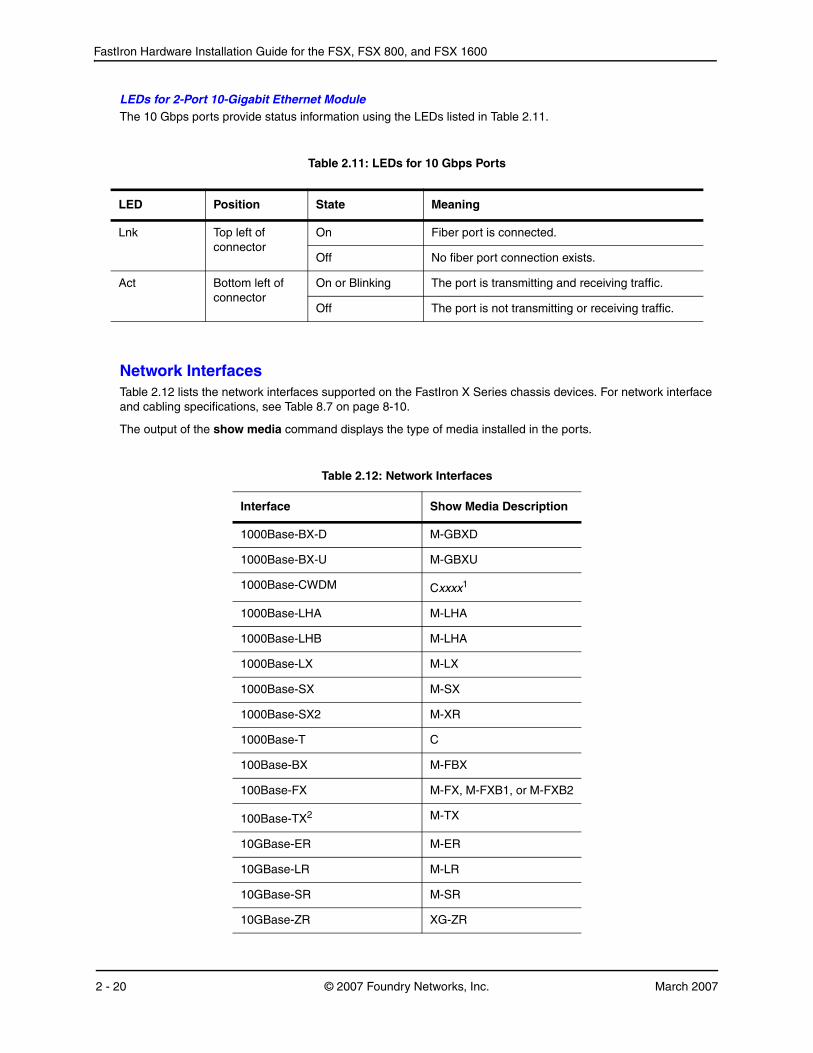
LEDs for 2-Port 10-Gigabit Ethernet ModuleThe 10 Gbps ports provide status information using the LEDs listed in Table 2.11.
Network InterfacesTable 2.12 lists the network interfaces supported on the FastIron X Series chassis devices. For network interface and cabling specifications, see Table 8.7 on page 8-10.
The output of the show media command displays the type of media installed in the ports.
Table 2.11: LEDs for 10 Gbps Ports
LED Position State Meaning
Lnk Top left of connector
On Fiber port is connected.
Off No fiber port connection exists.
Act Bottom left of connector
On or Blinking The port is transmitting and receiving traffic.
Off The port is not transmitting or receiving traffic.
Port RegionsPorts on the FastIron X Series chassis devices are grouped into regions. For a few features, such as port monitoring and unknown unicast configurations, you will need to know the region to which a port belongs. However, for most features, a port’s region does not affect configuration or operation of the feature. If a port’s region does affect configuration or operation of a feature, it is noted and described in the appropriate feature section of this guide.
• FSX Management Module:
• Ports 1 – 12
• FSX 800 and FSX 1600 Management Module with 2-port 10-GbE
FastIron Hardware Installation Guide for the FSX, FSX 800, and FSX 1600
The power supplies can be swapped in or out of the device while the device is running. You can remove and insert a power supply without opening the chassis. If the device contains redundant power supplies, you can remove one of the supplies without interrupting operation. The remaining supply provides enough power for all the ports.
Hardware specifications for the power supplies are in the chapter “Hardware Specifications” on page 8-1.
Part Number Description FSX FSX 800 FSX 1600
SX-ACPWR-SYS 12-volt AC X X X
SX-DCPWR-SYS 12-volt DC support added in release 02.4.00
The following power supplies can be installed in the FastIron X Series chassis devices:
• Non-POE devices:
• The 12-volt AC and DC power supplies (also called system (SYS) power supplies) provide power to one management module and up to eight non-POE interface modules. In the FSX and FSX 800, you can install a second 12-volt power supply for redundancy. The FSX 1600 comes with and requires two 12-volt power supplies and supports up to four 12-volt power supplies for redundancy.
• POE devices:
• The 12-volt AC and DC power supplies (also called system (SYS) power supplies) provide power to the management module, all non-POE interface modules (if applicable), and all ports on POE modules that do not require POE power or to which no power-consuming devices are attached. In the FSX and FSX 800, you can install a second 12-volt power supply for redundancy. The FSX 1600 comes with and requires two 12-volt power supplies and supports up to four 12-volt power supplies for redundancy.
• The 48-volt POE power supplies provide power to the POE daughter card, and ultimately to POE power-consuming devices. The number of POE power-consuming devices that one 48-volt power supply can support depends on the number of watts required by each power-consuming device. Each 48-volt power supply can provide a maximum of 1080 watts of POE power, and each POE port supports a maximum of 15.4 watts of power per POE power-consuming device. For example, if each POE power-consuming device attached to the Foundry device consumes 15.4 watts of power, one 48-volt supply will power up to 70 POE ports. You can install a second 48-volt supply for additional POE power.
• The 48-volt (220-volt input only) POE power supplies (added in release 03.5.00) provide power to the POE daughter card, and ultimately to POE power-consuming devices. The number of POE power-consuming devices that one 220-volt power supply can support depends on the number of watts required by each power-consuming device. Each 220-volt power supply can provide a maximum of 2160 watts of POE power, and each POE port supports a maximum of 15.4 watts of power per POE power-consuming device. For example, if each POE power-consuming device attached to the Foundry device consumes 15.4 watts of power, one 220-volt supply will power up to 140 POE ports. You can install a second 220-volt supply for additional POE power.
CAUTION: The POE power supply is designed exclusively for use with the FastIron X Series POE devices. The power supply produces extensive power to support 802.3af applications. Installing the power supply in a device other than the FastIron X Series POE will cause extensive damage to your equipment.
All power supplies are auto-sensing and auto-switching.
The power supplies are installed in the slots along the bottom of the chassis.
In the FSX and FSX 800 chassis, the 12-volt (system) power supplies occupy slot numbers 3 and 4 on the right, with the redundant supply in slot 4. The POE power supplies occupy slot numbers 1 and 2 on the left. Figure 2.16 shows power supply placement.
Figure 2.16 Power Supply Placement in the FSX and FSX 800
DC OK ALMAC OK DC OK ALMAC OK DC OK ALMAC OK DC OK ALMAC OK
POE Power Supply Slots SYS (12V) Power Supply Slots
FastIron Hardware Installation Guide for the FSX, FSX 800, and FSX 1600
In the FSX 1600 chassis, the system power supplies occupy slot numbers 1 – 4 in the top row with the redundant supplies in slot numbers 3 and 4. The POE power supplies occupy slot numbers 5 – 8 in the bottom row. Figure 2.17 shows power supply placement.
Figure 2.17 Power Supply Placement in the FSX 1600
The installed power supplies provide power to all chassis components, sharing the workload equally. If a power supply fails or overheats, the failed power supply’s workload is redistributed to the redundant power supply, if one is present.
The power supplies are hot swappable, which means you can remove and replace them without powering down the system. You can remove and insert a power supply without opening the chassis. If the device contains redundant 12-volt power supplies, you can remove one of the power supplies without interrupting operation. The remaining power supply provides enough power for all the ports. For more information about removing and installing the power supplies, see “Installing or Replacing a Power Supply” on page 7-17.
WARNING: The power supplies are hot swappable, which means they can be removed and replaced while the chassis is powered on and running. However, Foundry Networks recommends that you disconnect the power supply from the wall outlet before removing and replacing the supply. The device can be running while a power supply is being installed or removed, but the power supply itself should not be connected to a power source. Otherwise, you could be injured or the power supply or other parts of the device could be damaged.
Power Supply LEDs
Each power supply has three LEDs on its faceplate. The LEDs are described in Table 2.13.
AC OK DC OK ALM EJECT SYS AC OK DC OK ALM EJECT SYS AC OK DC OK ALM EJECT SYS AC OK DC OK ALM EJECT SYS
AC OK DC OK ALM EJECT POE AC OK DC OK ALM EJECT POE AC OK DC OK ALM EJECT POE AC OK DC OK ALM EJECT POE
The power supply is receiving AC power from an AC power source
OFF The power supply is not receiving power from an AC power source. You can do the following:
• Make sure that the power supply cord is connected securely to the wall outlet and the power supply.
• Make sure that the wall outlet is rated for 115/120V and 20A. If it is not, obtain a cable that is compatibly rated for the outlet.
• Make sure that the wall outlet has power.
DC IN (DC supply only)
Green (steady) The power supply is receiving DC power from a DC power source
OFF The power supply is not receiving power from a DC power source. You can do the following:
• Make sure that the power supply cables are connected securely to the power source and the power supply.
• Make sure that the DC power source is 48VDC @ 37.0 A.
• Make sure that the power source has power.
DC OUT ON – Green (steady)
The power supply is supplying DC output power to the chassis
OFF The power supply is not supplying DC output power to the chassis.
If this occurs and the AC OK (AC power supply) or DC IN (DC power supply) LED is Green, then there is a problem with the power supply and it must be replaced.
ALM OFF No alarms present and the power supply is in normal operating condition.
Amber There is an alarm present and the power supply is malfunctioning.
FastIron Hardware Installation Guide for the FSX, FSX 800, and FSX 1600
Cooling SystemThe cooling system is contained within the system’s fan tray assembly and modules. The following components comprise the cooling system:
• The FSX and FSX 800 each have six five-speed fans.
NOTE: Starting with release 03.0.00, the fans operate at four speeds instead of five speeds.
• The FSX 1600 has two five-speed fans in the rear of the chassis.
• One fan control module. The fan control module maintains the power to the fans, and controls the fan speed and the reporting of the fan status to the management module.
• Two temperature sensors on each management module, and one temperature sensor on each interface module
• One temperature sensor on each switch fabric module (FSX 800 and FSX 1600 only).
The fan tray in the FSX and FSX 800 chassis is located in the right side of each chassis. The FSX 1600 has two fan trays which are located in the top rear of the chassis.
Upon system startup, the fans operate at low speed, then adjust their speed based on the current temperature of the modules and the configured temperature thresholds, or by the manually configured fan speed.
By default, the system polls the temperature sensor on each module every 60 seconds to get a temperature reading. (For information about changing the default temperature polling interval, see “Changing the Temperature Polling Interval” on page 5-19.) Depending on the temperature readings for the modules, the system can do the following:
• Leave the fan speed as is
• Increase the fan speed
• Decrease the fan speed
• If the chassis exceeds the highest temperature threshold or shutdown temperature for five minutes, the system will shut down the device to prevent damage
If the temperature of a module exceeds specified high temperature thresholds, the system generates a Syslog message. The system can also power down the chassis if the temperature exceeds the highest threshold.
You can change default low and high temperature thresholds for modules and fan speeds. For more information, see “Changing Temperature Thresholds For Thermal Planes and Fan Speeds on the FSX (pre-release 03.0.00 only), and on the FSX 1600” on page 5-10.
The chassis ships with all fan components fully installed in the fan tray. For information about replacing the fan tray, see “Replacing the FSX and FSX 800 Fan Tray” on page 7-26 and “Replacing the FSX 1600 Fan Assemblies” on page 7-28.
Built-in Mounting BracketsThe front of each FSX and FSX 800 chassis has built-in mounting brackets that enable you to front-mount the chassis in a standard 19-inch (EIA310-D) rack. For instructions about using the built-in mounting brackets to mount the device in a rack, see “Installing a Chassis in a Rack” on page 3-6.
Alternatively, you can use a rack mount kit (ordered separately) to center-mount the FSX and FSX 800 using two L-shaped mounting brackets. The rack mount kit comes with instructions for installing the mounting brackets and mounting the device in a rack.
The FSX 1600 does not have built-in mounting brackets. Two brackets ship with the FSX 1600 that enable you to front-mount or center-mount the chassis in a rack.
Contact Foundry Networks for information about rack mount kits.
Layer 3 Routing Protocol Table SizesUse the show default values command to display Layer 3 routing protocol table sizes. The command output shows the default, maximum, and currently configured values. See the Foundry FastIron Configuration Guide for an example output.
This chapter describes hardware installation tasks for the FastIron X Series chassis devices.
WARNING: The procedures in this manual are for qualified service personnel.
This chapter contains the following topics:
• “Summary of Installation Tasks” on page 3-2
• “Unpacking a System” on page 3-3
• “Preparing the Installation Site” on page 3-5
• “Removing Extra Shipment Screws (FSX and FSX 800 only)” on page 3-5
• “Installing a Chassis in a Rack” on page 3-6
• “Removing the Slot Panels” on page 3-8
• “Installing the Management and Interface Modules” on page 3-8
• “Attaching a Management Station” on page 3-12
• “Powering On the System” on page 3-13
• “Verifying Proper Operation” on page 3-17
NOTE: Information about configuring IP addresses and connecting a FastIron X Series chassis device to other network devices is covered in the chapter “Connecting Network Devices and Checking Connectivity” on page 4-1.
FastIron Hardware Installation Guide for the FSX, FSX 800, and FSX 1600
Summary of Installation TasksTable 3.1 lists the tasks you must perform to install your FSX Switch and where to access detailed information that allows you to perform each task.
Table 3.1: FSX Hardware Installation Tasks
Task Number
Task Where to Find More Information
1 Unpack the chassis, and verify that all contents are present.
“Unpacking a System” on page 3-3
2 Review the installation cautions and warnings. “Installation Precautions” on page 3-3
3 Ensure that the physical environment that will host the chassis has proper cabling and ventilation.
“Preparing the Installation Site” on page 3-5
4 The FSX and FSX 800 chassis ships with extra screws installed in the right side of the chassis. These screws secure the fan tray assembly, protecting it from damage during shipment. You must remove these screws before installing the chassis.
“Removing Extra Shipment Screws (FSX and FSX 800 only)” on page 3-5
5 Install the chassis in a rack.
Because of the weight of a fully loaded chassis (97 lbs minimum), Foundry recommends mounting a chassis in a rack before installing the modules and power supplies.
“Installing a Chassis in a Rack” on page 3-6
6 The chassis ships with a slot panel installed in all module slots that don’t currently have a module installed. If you plan to install a module in a slot, you must remove the slot panel.
CAUTION: If you do not install a module in a slot, you must keep the slot panel in place. If you run the chassis with an uncovered slot, the system will overheat.
“Removing the Slot Panels” on page 3-8
7 Install the management module and interface modules in the chassis
“Installing the Management and Interface Modules” on page 3-8
8 Attach a management station to the management module’s serial (Console) port or a 10/100/1000 Ethernet port.
“Attaching a Management Station” on page 3-12
9 Power on the AC power supplies. “Powering On the System” on page 3-13
10 After the chassis is powered on, observe the LEDs or display the status of the modules using the CLI to determine that the chassis is operating properly.
Unpacking a SystemThe FastIron X Series ships with several items. Please review the list below and verify the contents. If any items are missing, please contact the place of purchase.
• FSX or FSX 800, or FSX 1600 chassis with the following installed:
• one or two 12-volt power supplies
• fan tray assembly or assemblies
• slot panels installed in all unoccupied slots
• The FSX 800 and FSX 1600 also come with two switch fabric modules already installed.
• CD-ROM containing software images and the user documentation (including this guide)
• Warranty card
• A 115V AC power cable for each AC power supply you purchase from Foundry
WARNING: If the installation requires a different power cord than the one supplied with the device, make sure you use a power cord displaying the mark of the safety agency that defines the regulations for power cords in your country. The mark is your assurance that the power cord can be used safely with the device.
Installation PrecautionsFollow these precautions when installing the chassis.
General Precautions
WARNING: All fiber-optic interfaces use Class 1 Lasers.
CAUTION: Do not install the device in an environment where the operating ambient temperature might exceed
40o C (104o F).
CAUTION: Make sure the air flow around the front, sides, and back of the device is not restricted.
CAUTION: If you do not install a module in a slot, you must keep the slot panel in place. If you run the chassis with an uncovered slot, the system will overheat.
CAUTION: Never leave tools inside the chassis.
Lifting Precautions
WARNING: A fully populated chassis is heavy. TWO OR MORE PEOPLE ARE REQUIRED WHEN LIFTING, HANDLING, OR MOUNTING THESE DEVICES.
WARNING: Make sure the rack or cabinet housing the device is adequately secured to prevent it from becoming unstable or falling over.
FastIron Hardware Installation Guide for the FSX, FSX 800, and FSX 1600
WARNING: Mount the devices you install in a rack or cabinet as low as possible. Place the heaviest device at the bottom and progressively place lighter devices above.
Power Precautions and Warnings
WARNING: The power supplies are hot swappable, which means they can be removed and replaced while the chassis is powered on and running. However, Foundry Networks recommends that you disconnect the power sup-ply from the wall outlet before removing and replacing the supply. The device can be running while a power supply is being installed or removed, but the power supply itself should not be connected to a power source. Otherwise, you could be injured or the power supply or other parts of the device could be damaged. .
WARNING: If the installation requires a different power cord than the one supplied with the device, make sure you use a power cord displaying the mark of the safety agency that defines the regulations for power cords in your country. The mark is your assurance that the power cord can be used safely with the device.
WARNING: Make sure to choose the appropriate circuit device depending on the number of AC power supplies installed in the chassis. The minimum current draw for the system is one AC power supply.
WARNING: Make sure that the power source circuits are properly grounded, then use the power cord supplied with the device to connect it to the power source.
WARNING: Disconnect the power cord from all power sources to completely remove power from the device.
CAUTION: Do not install the device in an environment where the operating ambient temperature might exceed
40o C (104o F).
CAUTION: All devices with DC power supplies are intended for installation in restricted access areas only. A restricted access area is where access can be gained only by service personnel through the use of a special tool, lock and key, or other means of security, and is controlled by the authority responsible for the location.
CAUTION: For a DC system, use a grounding wire of at least 6 American Wire Gauge (AWG). The 6 AWG wire should be attached to an agency-approved crimp connector crimped with the proper tool. The crimp connector should allow for securement to both ground screws on the enclosure. For the Ground lug, use UL listed Panduit crimp connector, P/N LCD6-10A, and two 10-32, PPH, screws to secure crimp connector to chassis. The ground-ing position is located on the side of the chassis adjacent to the ground symbol.
CAUTION: For the DC input circuit to the system, make sure there is a Listed 30 amp circuit breaker, minimum -48Vdc, double pole, on the input to the terminal block. The input wiring for connection to the product should be Listed copper wire, 8 AWG, marked VW-1, and rated minimum 90 degrees celcius.
CAUTION: Use a separate branch circuit for each AC power cord, which provides redundancy in case one of the circuits fails.
CAUTION: The POE power supply is designed exclusively for use with the FastIron X Series POE devices. The power supply produces extensive power to support 802.3af applications. Installing the power supply in a device other than the FastIron X Series POE will cause extensive damage to your equipment. Use a separate branch cir-cuit for each AC power cord, which provides redundancy in case one of the circuits fails.
CAUTION: Ensure that the device does not overload the power circuits, wiring, and over-current protection. To determine the possibility of overloading the supply circuits, add the ampere (amp) ratings of all devices installed on the same circuit as the device. Compare this total with the rating limit for the circuit. The maximum ampere rat-ings are usually printed on the devices near the input power connectors.
CAUTION: Make sure the power supply is properly inserted in the slot. Never insert the power supply upside down.
CAUTION: Do not attempt to install the power supply without first opening the latch on the front of the power supply. Attempting to install the power supply with a closed latch will result in mechanical damage to the power supply and power supply slot.
Preparing the Installation Site
Cabling InfrastructureEnsure that the proper cabling is installed in the site. For information on cabling, see the following sections in this guide:
• “Attaching a Management Station” on page 3-12
• “Connecting Network Devices” on page 4-4
• “Cable Specifications” on page 8-10
Installation LocationBefore installing the device, plan its location and orientation relative to other devices and equipment. Allow at least 3" of space at the front of the device for the fiber-optic and power cabling. Also, allow a minimum of 3" of space between the sides and the back of the device and walls or other obstructions.
Removing Extra Shipment Screws (FSX and FSX 800 only)The FSX and FSX 800 ship with two extra screws installed in the right side of the chassis. These screws secure the fan tray, protecting it from damage during shipment. You must remove these screws before installing the chassis. Figure 3.1 shows the location of the screws.
To perform this task, you need a #2 Phillips-head screwdriver.
Figure 3.1 Removing the extra screws used for shipment
FastIron Hardware Installation Guide for the FSX, FSX 800, and FSX 1600
Installing a Chassis in a RackBecause of the weight of a fully loaded chassis (97 lbs minimum), Foundry recommends mounting a chassis in a rack before installing the modules and power supplies.
In a standard 19-inch (EIA310-D) rack, you can install up to seven FSX or FSX 800 chassis devices, or up to three FSX 1600 chassis devices. You can flush mount the FSX and FSX 800 using the built-in mounting brackets on the front of the device. Alternatively, you can use the optional rack mount kit to center the chassis in a rack. The FSX 1600 does not have built-in mounting brackets. To mount the FSX 1600 in a rack, you will need to install the brackets in the rack mount kit that ships with the chassis, as shown in figure Figure 3.4.
Before performing this task, you should have an assembled rack and a #2 Phillips-head screwdriver.
Keep the following in mind when mounting a chassis in a rack:
WARNING: The Chassis devices are very heavy, especially when fully populated with modules and power sup-plies. TWO OR MORE PEOPLE ARE REQUIRED WHEN LIFTING, HANDLING, OR MOUNTING THESE DEVICES.
WARNING: Make sure the rack or cabinet housing the device is adequately secured to prevent it from becoming unstable or falling over.
WARNING: Mount the devices you install in a rack or cabinet as low as possible. Place the heaviest device at the bottom and progressively place lighter devices above.
For each FastIron X Series that you install in a rack, you must provide four mounting screws with which to secure the chassis.
To mount the chassis in a rack using the built-in mounting brackets, do the following:
1. Determine the position of each chassis in the rack.
2. Position two of the four mounting screws for each chassis that you plan to mount in the rack according to the spacings of the keyhole slots on the brackets (as shown in Figure 3.2). Do not secure the screws completely; leave approximately 1/4 inch of clearance between the back of the screw head and the rack.
Figure 3.2 Positioning two of four mounting screws in a rack.
3. Start by mounting the chassis that goes in the lowest position in the rack, as shown in Figure 3.3. With two or more people lifting the chassis, slip the wide portion of each keyhole slot over the corresponding screw in the rack.
Select holes in rack that match the keyholes in mounting brackets(in this case, the top for theleft-hand bracket and the bottomfor the right-hand bracket)
Figure 3.3 Mounting the FSX chassis in a rack - front mount
4. Slide the chassis down so that the screw heads are in the narrow portion of the keyhole slots.
5. Install the remaining two mounting screws through the opposite corners of the brackets into the rack.
6. Tighten all screws to secure the chassis in place.
7. Repeat Step 3 through Step 6 to mount each subsequent chassis in the same rack.
Installing Mounting Brackets on the FSX 1600 ChassisThe FSX 1600 chassis does not ship with mounting brackets installed. You will need to install the brackets yourself, using a #2 Phillips or flathead screwdriver. Mount the brackets as shown in Figure 3.4. Since the brackets are identical, you must rotate one bracket 90 degrees to fit on the opposite side from the first bracket.
Figure 3.4 Installing the Mounting Brackets on an FSX 1600 Chassis.
Repeat Step 3 through Step 6 to install the FSX 1600 chassis in the rack.
FastIron Hardware Installation Guide for the FSX, FSX 800, and FSX 1600
Removing the Slot PanelsThe chassis ships with a slot panel installed that covers each empty module slot, ensuring proper airflow within the chassis. If you plan to install a module in a particular slot, you must first remove the slot panel.
CAUTION: If you do not install a module in a slot, you must keep the slot panel in place. If you operate the chas-sis with an uncovered slot, the system will overheat.
Although the slot panels may differ in size, the procedure for removing them from the chassis is the same. The procedure in this section applies to all module slot panels.
You need a #2 Phillips-head or flathead screwdriver to perform this task.
To remove a slot panel, do the following:
1. Loosen the screws on either end of the slot panel with a #2 Phillips-head or flathead screwdriver.
2. Pull the slot panel out of the chassis, and store it in a safe place for future use.
Installing the Management and Interface ModulesThis section provides the procedures for installing the management and interface modules. Although the modules may differ in size and function, the procedure for installing each of them into the chassis is the same. The procecure described in this section applies to all FastIron X Series chassis devices.
The FSX 800 and FSX 1600 management modules are hot swappable, which means you can remove and insert them while the chassis is powered on and running. This does not apply to the FSX, which must be powered down before removing and inserting a management module.
NOTE: The management modules are dedicated, which means that you must install them in the appropriate chassis. If you attempt to install the FSX management module in the FSX 800, FSX 1600, or other Foundry chassis, the chassis and module will not function properly. Likewise, if you try to install the FSX 800 or FSX 1600 management module in the FSX or other Foundry chassis, the chassis and module will not function properly.
NOTE: The interface modules are interchangeable among all FastIron X Series chassis devices. However, if you try to install them in a Foundry chassis other than a FastIron X Series, the chassis and interface modules will not function properly.
Table 3.2 provides the chassis slot numbers into which you must install the modules. The following figures show the chassis with slot numbers:
• FSX – Figure 2.2 on page 2-5
• FSX 800 – Figure 2.4 on page 2-6
• FSX 1600 – Figure 2.6 on page 2-8
CAUTION: If you do not install a module in a slot, you must leave the slot panel installed in the slot. If you oper-ate the chassis with an uncovered empty slot, the system will overheat.
Before installing a module in the chassis, have the following on hand:
• An ESD wrist strap with a plug for connection to the ESD connector on the chassis.
WARNING: For safety reasons, the ESD wrist strap should contain a series 1 meg ohm resistor.
• A # Phillips-head or flathead screwdriver.
To install a module in the chassis, do the following:
1. If the FSX chassis is powered ON and you are installing a management module, power down the chassis and remove the power cables from the chassis power supplies.
NOTE: You do not need to power down the FSX 800 and FSX 1600 chassis when installing a management module. You can install modules in the FSX 800 and FSX 1600 chassis while it is powered on and running.
2. Put on the ESD wrist strap and ground yourself by inserting the plug into the ESD connector located on the chassis front.
3. Remove the module from its packaging.
4. Insert the management module or the interface module into the appropriate chassis slot and slide the card along the card guide until the ejectors on either side of the module move close to the module front panel.
5. Push the ejectors toward the center of the module to fully seat the module in the backplane.
6. Use the #2 Phillips-head or flathead screwdriver to tighten the two screws at either end of the module front panel.
The following illustrations show placement of the management and interface modules in the FastIron X Series chassis devices.
Figure 3.5 Installing a Management Module in the FSX Chassis
FastIron Hardware Installation Guide for the FSX, FSX 800, and FSX 1600
Attaching a Management StationYou can manage the FastIron X Series system in the following ways:
• You can connect a PC or terminal to the management module’s serial (Console) port or 10/100/1000 Ethernet port and access the system directly from the PC or terminal, or from a Telnet connection to the PC or terminal. For more information, see “Attaching a PC or Terminal to the Console Port or 10/100/1000 Copper Port” on page 3-12.
• You can connect the FastIron X Series switch to your existing management network and manage the switch, along with other network devices, from a management station. To do this, you can connect a switch to a Gigabit Ethernet port on the management module. For more information, see “Attaching a Switch to an Ethernet Port” on page 3-12.
NOTE: The management network into which you can connect a Gigabit Ethernet port must be separate and isolated from the network over which user packets are switched and routed as shown in Figure 2.8 on page 2-10.
Attaching a PC or Terminal to the Console Port or 10/100/1000 Copper PortThe management module’s Console port, which has a male DB-9 serial connector, and 10/100/1000 Ethernet copper port(s), which have RJ-45 UTP connectors, allow you to attach a PC or terminal. From the Console port, you can access the system’s CLI directly from the PC or terminal or via a Telnet connection to the PC or terminal. From the Ethernet port, you can access the system’s CLI or Web management interface directly from the PC or terminal or via a Telnet connection to the PC or terminal.
Before performing this task, you need the following items:
• PC running a terminal emulation application or a terminal.
• If connecting the PC or terminal to the Console port, a straight-through EIA/TIA DB-9 serial cable with one end terminated in a female DB-9 connector and the other end terminated in a male or female DB-9 or DB-25 connector, depending on the specifications of your PC or terminal. You can order the serial cable separately from Foundry Networks or build your own cable. If you prefer to build your own, see the pinout information in “Serial (Console) Port Pinouts” on page 8-8.
• If connecting the PC or terminal to a Gigabit Ethernet copper port, a category 5 UTP crossover cable, which you must supply. For information about the port pin assignments, see “10/100 and Gigabit Port Pinouts” on page 8-9.
To attach a PC or terminal to the Console port or Gigabit Ethernet copper port, do the following:
1. Connect a PC or terminal to the Console port or a 10/100/1000 Ethernet port using the appropriate cable.
2. Open the terminal emulation program, and set the session parameters as follows:
• Baud: 9600 bps
• Data bits: 8
• Parity: None
• Stop bits: 1
• Flow control: None
Attaching a Switch to an Ethernet PortThe FSX 800 and FSX 1600 management module’s 10/100/1000 Ethernet copper port and the FSX management module’s combination Gigabit Ethernet copper and fiber ports enable you to attach a networking switch. A management station in your existing management network can then access the Foundry switch using the IronView Network Manager.
For more information, see “Connecting Network Devices” on page 4-4.
Powering On the SystemAfter you complete the hardware installation, you can power on the system. Verify that all modules and power supplies are fully and properly installed and no module slots are uncovered.
Note the following before powering on the system:
CAUTION: If you do not install a module in a slot, you must keep the slot panel in place. If you run the chassis with an uncovered slot, the system will overheat.
WARNING: If the installation requires a different power cord than the one supplied with the device, make sure you use a power cord displaying the mark of the safety agency that defines the regulations for power cords in your country. The mark is your assurance that the power cord can be used safely with the device.
NOTE: If the wall outlet is not rated 115/120V and 20A, stop and get the appropriate cable for the outlet. Make sure you obtain a power cord displaying the mark of the safety agency that defines the regulations for power cords in your country. The mark is your assurance that the power cord can be used safely with the device.
NOTE: The wall outlet should be installed near the equipment and should be easily accessible.
NOTE: The FastIron X Series switch is designed to provide uninterrupted service even when you insert or remove the interface modules. Therefore, the system does not have a separate on/off power switch. To turn the system off, simply unplug the power cord(s).
Connecting AC Power to the ChassisAC power is supplied though an AC power cord that is installed at the rear of the chassis.
1. At the rear of the chassis, locate the power receptacle where the power supplies have been installed.
2. Lift the cord-retainer and connect a Foundry-supplied AC power cord to the power supply.
WARNING: If the installation requires a different power cord than the one supplied with the device, make sure you use a power cord displaying the mark of the safety agency that defines the regulations for power cords in your country. The mark is your assurance that the power cord can be used safely with the device.
4. Connect the power cord to the wall outlet.
5. Observe the LEDs on the power supply front panel. The AC OK and DC OK LEDs should be green (steady), which indicates the power supply is providing power to the chassis components. If it is amber or OFF, the power supply is not providing power to the chassis components. The ALM LED should be OFF.
Connecting DC Power to the Chassis
You can use a DC power source for the Foundry chassis. This is supported through use of a DC to DC power supply. DC power must be supplied at 48 V and 30 A.
To perform this task, you need the following items:
• Flathead screwdriver
• Phillips-head screwdriver
• #6 AWG wire (grounding wire)
• #8 AWG wire (input wire)
• Crimping tool
To connect a DC power source:
1. Crimp #6 AWG ground wire and connect it to the ground position on the chassis. The ground position is located on the side or rear of the chassis next to the ground symbol. See the illustrations in Step 4.
2. Use a flathead screwdriver to remove the two screws holding the transparent cover over the power supply lugs. The following illustration shows the location of the screws and lugs.
3. Use a Phillips-head screwdriver to remove each of the power lugs.
6. Connect the wire to your DC power source making sure to connect the positive and negative supply wires to the correct location as marked on the power supply.
7. Observe the LEDs on the power supply front panel. The DC IN and DC OUT LEDs should be green (steady), which indicates the power supply is providing power to the chassis components. If it is amber or OFF, the power supply is not providing power to the chassis components. The ALM LED should be OFF.
Verifying Proper OperationTo verify the proper operation of the chassis after power on, you can do the following:
• Observe the LEDs
• Display the status of the modules using the CLI
Observing the LEDsAfter the FastIron X Series chassis device powers on, you can observe its LEDs to verify that it initialized successfully. Table 3.3 outlines the LEDs, the desired state of each LED, possible abnormal states of each LED, and what to do if an LED indicates an abnormal state.
Table 3.3: Desired and Abnormal LED States After System Power On
LED Desired State Meaning Abnormal State
Meaning/Action
Management Module
Active On The module is functioning as the active management module.
Off Neither of the management module(s) is managing the switch fabric and interface modules.
A problem could have occurred during initialization. Check your attached PC or terminal for possible error messages.
Pwr On The module is receiving power.
Off The module is not receiving power. You can do the following:
• Make certain that the module is installed properly. For more information, see “Installing the Management and Interface Modules” on page 3-8.
• If using AC power supplies, see the entry for the AC power supply LED in this table for more information.
FastIron Hardware Installation Guide for the FSX, FSX 800, and FSX 1600
10/100/1000 Ethernet Port
On – Green A link is established with the remote port.
Off A link is not established with the remote port. You can do the following:
• Verify that the connection to the other device has been properly made. Also, make certain that the other device is powered on and operating correctly.
• Try using a different cable.
10/100/1000 Ethernet Port
On or blinking – Yellow
The port is transmitting and receiving packets.
Off for an extended period
The port is not transmitting or receiving packets.
You can check the other 10/100/1000 Ethernet port LED to make sure a link is established with the remote port. If not, take the actions described in the Meaning/Action column for the other 10/100/1000 Ethernet port LED.
Interface Module
Link/Activity On or blinking A link is established with the remote port and the port is transmitting and receiving user packets.
Off At this stage of the installation, you have not yet cabled the Gigabit Ethernet ports, so this LED will be off.
After cabling this port, if this LED is off, a link is not established with the remote port.
POE (if applicable)
On – Green The port is enabled, a power-consuming device has been detected, and the module is supplying power to the device.
Off The port is not providing in-line power.
Table 3.3: Desired and Abnormal LED States After System Power On (Continued)
If a problem persists after taking action described in this table, contact Foundry’s technical support.
Displaying the Module StatusAfter you have attached a PC or terminal to the management module’s Console port or Ethernet port and the Foundry device has initialized successfully, press Enter to display the following CLI prompt in the terminal emulation window:
FastIron>
AC and DC Power Supplies
AC OK (AC supply only)
ON – Green (steady)
The power supply is receiving AC power from an AC power source
OFF The power supply is not receiving power from an AC power source. You can do the following:
• Make sure that the power supply cord is connected securely to the wall outlet and the power supply.
• Make sure that the wall outlet is rated for 115/120V and 20A. If it is not, obtain a cable that is compatibly rated for the outlet.
• Make sure that the wall outlet has power.
DC IN (DC supply only)
Green (steady) The power supply is receiving DC power from a DC power source
OFF The power supply is not receiving power from a DC power source. You can do the following:
• Make sure that the power supply cables are connected securely to the power source and the power supply.
• Make sure that the DC power source is 48VDC @ 30 A.
• Make sure that the power source has power.
DC OUT ON – Green (steady)
The power supply is supplying DC output power to the chassis
OFF The power supply is not supplying DC output power to the chassis.
If this occurs and the AC OK (AC power supply) or DC IN (DC power supply) LED is Green, then there is a problem with the power supply and it must be replaced.
ALM OFF No alarms present and the power supply is in normal operating condition.
Amber There is an alarm present and the power supply is malfunctioning.
Verify the AC or DC input and DC output voltages.
Table 3.3: Desired and Abnormal LED States After System Power On (Continued)
FastIron Hardware Installation Guide for the FSX, FSX 800, and FSX 1600
If you do not see this prompt:
1. Make sure the cable is securely connected to your PC or terminal and the Console port or Ethernet port.
2. Check the settings in your terminal emulation program. In addition to the session settings listed in “Attaching a PC or Terminal to the Console Port or 10/100/1000 Copper Port” on page 3-12, make sure the terminal emulation session is running on the same serial port you attached to the Console port.
If you see the prompt FastIron> or similar, you are connected to the system and can display the status of the modules using the CLI. Enter the show module command at any CLI level.
The following shows the output of the show module command when entered on the FSX:
The following shows the output of the show module command when entered on the FSX 800. The display output is similar on the FSX 1600.
Syntax: show module
The Status column shows the module status. The status can be one of the following:
• OK – The module is up and running
• ACTIVE – This applies to the FSX 800 and FSX 1600 management and switch fabric modules only. This indicates that the module is the active module as opposed to the standby module.
• STANDBY – This applies to the FSX 800 and FSX 1600 management and switch fabric modules only. This indicates that the module is the standby module as opposed to the active module.
• FAILED – The management module was unable to bring up an interface module properly. If you observe this
FastIron# show module
Module Status Ports Starting MACS1: SX-424C 24-port Gig Copper Module OK 24 00e0.5200.0100S2: SX-424C 24-port Gig Copper Module OK 24 00e0.5200.0120S3: S4: SX-424C 24-port Gig Copper Module OK 24 00e0.5200.0160S5: SX-424C 24-port Gig Copper Module OK 24 00e0.5200.0180S6: SX-424C 24-port Gig Copper Module OK 24 00e0.5200.01a0S7: S8: S9: SX-12GM-4 12-port Management Module OK 12 02e0.5200.0120
FastIron SX 800 Switch# show module
Module Status Ports Starting MAC F1: SX-FISF Switch Fabric active F2: SX-FISF Switch Fabric active S1: SX-F424C 24-port Gig Copper OK 24 00e0.beef.0000 S2: SX-F424C 24-port Gig Copper OK 24 00e0.beef.0000 S3: SX-F42XGW 2-port 10G LAN/WAN OK 2 00e0.beef.0030 S4: SX-F424C 24-port Gig Copper OK 24 00e0.beef.0048 S5: SX-F42XGW 2-port 10G LAN/WAN OK 2 00e0.beef.0060 S6: SX-F424C 24-port Gig Copper OK 24 00e0.beef.0078 S7: SX-F424C 24-port Gig Copper OK 24 00e0.beef.0090 S8: SX-F424F 24-port Gig Fiber OK 24 00e0.beef.00a8 S9: SX-FIZMR4 0-port Management Active 0 { Status : OK }S10: SX-FIZMR4 0-port Management Standby 0 { Status : Absent }
status, make certain that the interface module is installed properly. For more information, see “Installing the Management and Interface Modules” on page 3-8.
This chapter provides the details for connecting network devices and checking network connectivity.
WARNING: The procedures in this manual are for qualified service personnel.
Table 4.1 lists the tasks you must perform to connect your Foundry device, and how to troubleshoot any problems that can arise.
Assigning Permanent PasswordsBy default, the CLI is not protected by passwords. To secure CLI access, Foundry strongly recommends assigning passwords.
NOTE: You cannot assign a password using the Web management interface. You can assign passwords using IronView Network Manager if an enable password for a Super User has been configured on the device.
The CLI contains the following access levels:
• User EXEC – The level you enter when you first start a CLI session. At this level, you can view some system information but you cannot configure system or port parameters.
• Privileged EXEC – This level is also called the Enable level and can be secured by a password. You can perform tasks such as manage files on the flash module, save the system configuration to flash, and clear caches at this level.
Table 4.1: Network Connectivity Tasks
Step Task Page
1 Secure access to the CLI by assigning passwords. 4-1
2 Configure IP addresses for the management, Ethernet, virtual, and loopback interfaces.
4-3
3 Connect your device to another networking device. 4-4
4 Test a port for connectivity to other networking devices using the ping and traceroute commands.
FastIron Hardware Installation Guide for the FSX, FSX 800, and FSX 1600
• CONFIG – The configuration level. This level lets you configure the system’s IP address and configure switching and routing features. To access the CONFIG mode, you must already be logged into the Privileged level of the EXEC mode.
You can set the following levels of Enable passwords:
• Super User – Allows complete read-and-write access to the system. This is generally for system administrators and is the only password level that allows you to configure passwords.
NOTE: You must set a super user password before you can set other types of passwords.
• Port Configuration – Allows read-and-write access for specific ports but not for global (system-wide) parameters.
• Read Only – Allows access to the Privileged EXEC mode and CONFIG mode but only with read access.
To set passwords:
1. At the opening CLI prompt, enter the following command to change to the Privileged level of the EXEC mode:
FastIron SuperX Switch> enable
2. Access the CONFIG level of the CLI by entering the following command:
FastIron SuperX Switch# configure terminal
FastIron SuperX Switch(config)#
3. Enter the following command to set the super-user password:
Recovering from a Lost PasswordBy default, the CLI does not require passwords. However, if someone has configured a password for the device but the password has been lost, you can regain super-user access to the device using the following procedure.
NOTE: Recovery from a lost password requires direct access to the serial port and a system reset.
To recover from a lost password:
1. Start a CLI session over the serial interface to the Foundry device.
2. Reboot the device.
3. While the system is booting, before the initial system prompt appears, enter b to enter the boot monitor mode.
4. Enter no password at the prompt. (You cannot abbreviate this command.)
5. Enter boot system flash primary at the prompt. This command causes the device to bypass the system password check.
6. After the console prompt reappears, assign a new password.
Connecting Network Devices and Checking Connectivity
Configuring IP AddressesYou must configure at least one IP address using the serial connection to the CLI before you can manage the system using the other management interfaces. In addition, Foundry routers require an IP subnet address for the subnet in which you plan to place them in your network.
Foundry devices support both classical IP network masks (Class A, B, and C subnet masks, and so on) and Classless Interdomain Routing (CIDR) network prefix masks.
• To enter a classical network mask, enter the mask in IP address format. For example, enter “209.157.22.99 255.255.255.0” for an IP address with a Class-C subnet mask.
• To enter a prefix number for a network mask, enter a forward slash ( / ) and the number of bits in the mask immediately after the IP address. For example, enter “209.157.22.99/24” for an IP address that has a network mask with 24 significant (“mask”) bits.
By default, the CLI displays network masks in classical IP address format (example: 255.255.255.0). You can change the display to the prefix format. See the Foundry FastIron X-Series Configuration Guide for more information.
NOTE: If your network uses a BootStrap Protocol (BootP) server or a Dynamic Host Configuration Protocol (DHCP) server, you can allow the Foundry device to obtain IP addresses for the hosts on the network.
Devices Running Layer 3 SoftwareBefore attaching equipment to a Foundry router, you must assign an interface IP address to the subnet on which the router will be located. You must use the serial connection to assign the first IP address. For subsequent addresses, you also can use the CLI through Telnet or the Web management interface.
By default, you can configure up to 24 IP interfaces on each port, virtual interface, and loopback interface. You can increase this amount to up to 64 IP subnet addresses per port by increasing the size of the subnet-per-interface table. See the Foundry FastIron X-Series Configuration Guide for more information.
The following procedure shows how to add an IP address and mask to a router port.
1. At the opening CLI prompt, enter enable.
FastIron SuperX Router> enable
2. Enter the following command at the CLI Privileged EXEC level prompt, then press Enter. This command erases the factory test configuration if still present:
FastIron SuperX Router# erase startup-config
CAUTION: Use the erase startup-config command only for new systems. If you enter this command on a system you have already configured, the command erases the configuration. If you accidentally do erase the configuration on a configured system, enter the write memory command to save the running configuration to the startup-config file.
3. Access the configuration level of the CLI by entering the following command:
FastIron SuperX Router(config)# Global CONFIG Level
4. Configure the IP addresses and mask addresses for the interfaces on the router.
FastIron SuperX Router(config)# int e 1/5
FastIron SuperX Router(config-if-e1000-5)# ip address 192.22.3.44 255.255.255.0
NOTE: You can use the syntax ip address <ip-addr>/<mask-bits> if you know the subnet mask length. In the above example, you could enter ip address 192.22.3.44/24.
FastIron Hardware Installation Guide for the FSX, FSX 800, and FSX 1600
Syntax: enable [<password>]
Syntax: configure terminal
Syntax: [no] ip address <ip-addr> <ip-mask> [secondary]
or
Syntax: [no] ip address <ip-addr>/<mask-bits> [secondary]
Use the secondary parameter if you have already configured an IP address within the same subnet on the interface.
Devices Running Layer 2 SoftwareTo configure an IP Address to a device running Layer 2 software:
1. At the opening CLI prompt, enter enable.
FastIron SuperX Switch> enable
2. Enter the following command at the Privileged EXEC level prompt (for example, FastIron#), then press Enter. This command erases the factory test configuration if still present:
FastIron SuperX Switch# erase startup-config
CAUTION: Use the erase startup-config command only for new systems. If you enter this command on a system you have already configured, the command erases the configuration. If you accidentally do erase the configuration on a configured system, enter the write memory command to save the running configuration to the startup-config file.
3. Access the configuration level of the CLI by entering the following command:
Connecting Network Devices and Checking Connectivity
Connecting to Ethernet or Fast Ethernet HubsFor copper connections to Ethernet hubs, a 10/100Base-TX or 1000Base-T switch, or another Foundry device, a crossover cable is required (Figure 4.1 and Figure 4.2). If the hub is equipped with an uplink port, it will require a straight-through cable instead of a crossover cable.
NOTE: The 802.3ab standard (automatic MDI/MDIX detection) calls for automatic negotiation of the connection between two 1000Base-T ports. Therefore, a crossover cable may not be required; a straight-through cable may work as well. For more information about this feature, see the Foundry FastIron X-Series Configuration Guide.
Figure 4.1 UTP crossover cable
Figure 4.2 Cat-5 crossover cable for 1000Base-T
NOTE: The 802.3ab standard calls for automatic negotiation of the connection between two 1000Base-T ports. Consequently, a crossover cable may not be required; a straight-through cable may work as well.
Connecting to Workstations, Servers, or RoutersStraight-through UTP cabling is required for direct UTP attachment to workstations, servers, or routers using network interface cards (NICs).
FastIron Hardware Installation Guide for the FSX, FSX 800, and FSX 1600
Fiber cabling with LC connectors is required for direct attachment to Gigabit NICs or switches and routers.
NOTE: The 802.3ab standard (automatic MDI/MDIX detection) calls for automatic negotiation of the connection between two 1000Base-T ports. Therefore, a crossover cable may not be required; a straight-through cable may work as well. For more information about this feature, see the Foundry FastIron X-Series Configuration Guide.
Connecting a Network Device to a Fiber Port on the Foundry DeviceFor direct attachment from the Foundry device to a Gigabit NIC, switch, or router, fiber cabling with an LC connector is required.
To connect a Foundry device to another network device using a fiber port, you must do the following:
• Install a fiber optic module (SFP transceiver or mini-GBIC for Gigabit Ethernet ports, or XFP-MSA transceiver for 10-Gigabit Ethernet ports)
• Cable the fiber optic module
The following sections provide information about performing these tasks.
Installing a Fiber Optic Module
You must install a fiber optic module in each Gigabit Ethernet and 10-Gigabit Ethernet fiber port you want to use.
WARNING: All fiber-optic interfaces use Class 1 Lasers.
NOTE: See “Installation Precautions” on page 3-3 for other hardware installation precautions.
NOTE: Some older SFP modules (mini-GBICs for Gigabit Ethernet ports) have latching mechanisms which are larger than the newer parts. These latches could interfere with one another when inserted side by side into a module. Avoid using these mini-GBICs side by side in the same module. These older modules are identified by the number PL-XPL-00-S13-22 or PL-XPL-00-L13-23 above the Serial Number. All newer mini-GBICs do not have this limitation.
Before installing a fiber optic module, have the following on hand:
• An ESD wrist strap with a plug for connection to the ESD connector on the chassis.
WARNING: For safety reasons, the ESD wrist strap should contain a series 1 meg ohm resistor.
To install a fiber optic module into a Gigabit Ethernet or 10-Gigabit Ethernet port, do the following:
1. Put on the ESD wrist strap and ground yourself by inserting the plug into the ESD connector located in the lower right corner of the chassis front.
2. Remove the module from its protective packaging.
3. If necessary, remove the metal cover from the port on the interface module’s control panel.
4. Gently insert the fiber-optic module into the port until the module clicks into place. The fiber-optic modules are keyed to prevent incorrect insertion.
Cabling a Fiber Optic Module
To cable a fiber-optic module, do the following:
1. Remove the protective covering from the fiber optic module and store the covering for future use.
2. Before cabling a fiber optic module, Foundry strongly recommends cleaning the cable connectors and the port connectors. For more information, see “Cleaning Fiber Optic Modules” .
3. Gently insert the cable connector(s) (a tab on each connector should face upward) into the port connector(s) until the tabs lock into place.
Connecting Network Devices and Checking Connectivity
Cleaning Fiber Optic Modules
To avoid problems with the connection between the fiber optic module (SFP (mini-GBIC) or XFP) and the fiber cable connectors, Foundry strongly recommends cleaning both connectors each time you disconnect and reconnect them. In particular, dust can accumulate in the connectors and cause problems such as reducing the optic launch power.
To clean the fiber cable connectors, Foundry recommends using the fiber-optic reel-type cleaner that shipped with your chassis. You can also purchase this type of cleaner from the following Website:
http://www.fisfiber.com
When not using an SFP or XFP connector, make sure to keep the protective covering on.
Automatic MDI/MDIX DetectionAll 10/100 and Gigabit Ethernet Copper ports on the Foundry FastIron devices support automatic Media Dependent Interface (MDI) and Media Dependent Interface Crossover (MDIX) detection. This feature is enabled on all 10/100 and Gigabit copper ports by default. For each port, you can disable auto MDI/MDIX, designate the port as an MDI port, or designate the port as an MDIX port.
For more information about this feature and how configure it, see the Foundry FastIron X-Series Configuration Guide.
Testing Network ConnectivityAfter you install the network cables, you can test network connectivity to other devices by pinging those devices. You also can observe the LEDs related to network connection and perform trace routes.
Pinging an IP AddressTo verify that a Foundry device can reach another device through the network, enter a command such as the following at any level of the CLI on the Foundry device:
See the Foundry Switch and Router Command Line Interface Reference for information about the parameters.
NOTE: If you address the ping to the IP broadcast address, the device lists the first four responses to the ping.
Observing LEDsAfter you install the network cables, you can observe certain LEDs to determine if the network connections are functioning properly. Table 4.2 outlines the LEDs related to the network connections, the desired state of each LED, possible abnormal states of each LED, and what to do if an LED indicates an abnormal state.
FastIron Hardware Installation Guide for the FSX, FSX 800, and FSX 1600
NOTE: Some modules use combined link and activity LEDs.
If a problem persists after taking these actions, contact Foundry’s technical support.
Tracing a RouteTo determine the path through which a Foundry device can reach another device, enter a command such as the following at any level of the CLI on the Foundry device:
FastIron SuperX Router> traceroute 192.33.4.7
Table 4.2: Network Connection-Related LED States
LED Desired State
Meaning Abnormal State
Meaning/Action
Link On (Green)
A link is established with the remote port.
Off A link is not established with the remote port. You can do the following:
• Verify that the connection to the other network device has been properly made. Also, make certain that the other network device is powered on and operating correctly.
• Verify that the transmit port on the Foundry device is connected to the receive port on the other network device, and that the receive port on the Foundry device is connected to the transmit port on the other network device. If you are not certain, remove the two cable connectors from the port connector and reinsert them in the port connector, reversing their order.
• Dust may have accumulated in the cable connector or port connector. For information about cleaning the connectors, see “Cleaning Fiber Optic Modules” on page 4-7.
• If the other actions don’t resolve the problem, try using a different port or a different cable.
Active On or blinking (Yellow)
The port is transmitting and receiving user packets.
Off for an extended period.
The port is not transmitting or receiving user packets. You can do the following:
• Check the Link LED to make sure the link is still established with the remote port. If not, take the actions described in the Meaning/Action column for the Link LED.
• Verify that the port has not been disabled through a configuration change. You can use the CLI. If you have configured an IP address on the device, you also can use the Web management interface or IronView Network Manager.
The CLI displays trace route information for each hop as soon as the information is received. Traceroute requests display all responses to a given TTL. In addition, if there are multiple equal-cost routes to the destination, the Foundry device displays up to three responses by default.
See the Foundry Switch and Router Command Line Interface Reference for information about the command syntax.
Troubleshooting Network ConnectionsTo resolve problems that may arise with network connections:
• For the indicated port, verify that both ends of the cabling (at the Foundry device and the connected device) are snug.
• Verify that the Foundry device and the connected device are both powered on and operating correctly.
• Verify that you have used the correct cable type for the connection:
• For twisted-pair connections to an end node, use straight-through cabling.
• For fiber-optic connections, verify that the transmit port on the device is connected to the receive port on the connected device, and that the receive port on device is connected to the transmit port on the connected device.
• Verify that the port has not been disabled through a configuration change. You can use the CLI. If you have configured an IP address on the device, you also can use the Web management interface or IronView Network Manager.
• For copper ports, you can test the cable using Virtual Cable Testing. See “Using Virtual Cable Testing to Diagnose a Cable” on page 4-9.
• If the other procedures don’t resolve the problem, try using a different port or a different cable.
Using Virtual Cable Testing to Diagnose a CableFastIron X Series devices support Virtual Cable Test (VCT) technology. VCT technology enables you to diagnose a conductor (wire or cable) by sending a pulsed signal into the conductor, then examining the reflection of that pulse. This method of cable analysis is referred to as Time Domain Reflectometry (TDR). By examining the reflection, the Foundry device can detect and report cable statistics such as, local and remote link pair, cable length, and link status.
Configuration Notes
• This feature is supported on copper ports only. It is not supported on fiber ports.
• The port to which the cable is connected must be enabled when you issue the command to diagnose the cable. If the port is disabled, the command is rejected.
• If the port is operating at 100 Mbps half-duplex, the TDR test on one pair will fail.
• If the remote pair is set to forced 100 Mbps, any change in MDI/MDIX may cause the device to interpret the Multilevel Threshold-3 (MLT-3) as a reflected pulse, in which case, the device will report a faulty condition. In this scenario, it is recommended that you run the TDR test a few times for accurate results.
Command Syntax
To diagnose a cable using TDR, enter commands such as the following at the Privileged EXEC level of the CLI:
FastIron# phy cable-diag tdr 1
The above command diagnoses the cable attached to port 1.
FastIron Hardware Installation Guide for the FSX, FSX 800, and FSX 1600
Viewing the Results of the Cable Analysis
To display the results of the cable analysis, enter a command such as the following at the Privileged EXEC level of the CLI:
Syntax: show cable-diag tdr <slot-num/port-num>
Table 4.3 defines the fields shown in the command output.
Table 4.3: Cable Statistics
This Line... Displays...
Port The interface that was tested.
Speed The port’s current line speed.
Local pair The local link name.
Pair Length The cable length when terminated, or the distance to the point of fault when the line is not up.
Remote pair The remote link name.
Pair status The status of the link. This field displays one of the following:
• Terminated: The link is up.
• Shorted: A short is detected in the cable.
• Open: An opening is detected in the cable.
• ImpedMis: The impedance is mismatched.
• Failed: The TDR test failed.
FastIron#sh cable-diag tdr 1
Port Speed Local pair Pair Length Remote pair Pair status--------- ----- ---------- ----------- ----------- -----------01 1000M Pair A <50M Pair B Terminated Pair B <50M Pair A Terminated Pair C <50M Pair D Terminated Pair D <50M Pair C Terminated
FastIron Hardware Installation Guide for the FSX, FSX 800, and FSX 1600
The following shows an example of the show chassis command output on a FSX running a release prior to 03.0.00. In software releases 03.0.00 and later, the show chassis command output on a FSX looks similar to the one shown in the next example.
The following shows an example of the show chassis command output on the FSX 800. The display is similar on the FSX running software release 03.0.00 or later.
FastIron SX 800 Router#show chassisPower supply 1 not presentPower supply 2 not presentPower supply 3 (H1250C - AC - Regular) present, status okPower supply 4 not present
FastIron SX 1600 Router#show chassisPower supply 1 not presentPower supply 2 not presentPower supply 3 not presentPower supply 4 (30351100 - AC - Regular) present, status ok Power supply 5 not present Power supply 6 not present Power supply 7 not present Power supply 8 present, status failed, reason NO AC INPUT
Fan 1 ok, speed (auto): 1<->2<->[[3]]<->4<->5 Fan 2 ok, speed (auto): 1<->2<->[[3]]<->4<->5
FastIron Hardware Installation Guide for the FSX, FSX 800, and FSX 1600
The show chassis display shows the following information:
Table 5.1: Chassis Status and Temperature Information
This Field... Displays...
Powers
Power Supply Indicates whether a power supply is installed in the specified power supply slot and the status of the power supply, which can be one of the following:
• OK – The power supply is functioning properly and supplying power to the chassis and installed modules.
• Failed – The power supply is not functioning and is not supplying power to the chassis and installed modules.
Starting in software release 03.0.00, this field also indicates:
• the power supply model number
• whether the supply is AC or DC
• whether the supply is regular or POE.
On the FSX and FSX 800, Power Supply 1 is the left-most slot, and Power Supply 4 is the right-most slot. These numbers assume you are facing the front of the chassis, not the rear.
On the FSX 1600, Power Supply 1 is the top left-most slot, Power Supply 4 is the top right-most slot, Power Supply 5 is the bottom left-most slot, and Power Supply 8 is the right-most slot. These numers assume you are facing the front of the chassis, not the rear.
Fans
Fan <number> For the FSX and FSX 800, this field displays nformation about fans 1 through 6. Fan locations are as follows:
• Fan 1 – Left-most fan in bottom row
• Fan 2 – Middle fan in bottom row
• Fan 3 – Right-most fan in bottom row
• Fan 4 – Left-most fan in top row
• Fan 5 – Middle fan in top row
• Fan 6 – Right-most fan in top row
For the FSX 1600, this field displays information about fans 1 and 2. Fan locations are as follows:
• Fan 1 – This is Fan A and is the right-most fan in the rear of the chassis.
• Fan 2 – This is Fan B and is the right-most fan in the rear of the chassis.
<Fan status> The status of a fan can be one of the following:
• OK – The fan is functioning properly and is keeping the temperature of each module within an acceptable temperature range.
• Failed – The fan is not functioning properly or the fan control module cannot control the fan.
Speed <Operating mode> The operating mode of a fan can be one of the following:
• Auto (automatic) – This is the default
• Manual
<Current fan speed> In release 03.0.00 and later, the fan speed for the FSX and FSX 800 can be one of the following:
• 1 (low) – The fan is functioning at 25 percent of capacity.
• 2 (medium-low) – The fan is functioning at 37 percent of capacity.
• 3 (medium) – The fan is functioning at 50 percent of capacity.
• 4 (high) – The fan is functioning at 100 percent of capacity.
In releases prior to 03.0.00 and for the FSX 1600 chassis, the fan speed can be one of the following:
• 1 (low) – The fan is functioning at 20 percent of capacity.
• 2 (medium-low) – The fan is functioning at 40 percent of capacity.
• 3 (medium) – The fan is functioning at 60 percent of capacity.
• 4 (medium-high) – The fan is functioning at 80 percent of capacity.
• 5 (high) – The fan is functioning at 100 percent of capacity.
The current fan speed is shown in double brackets.
Temperature Readings
Fan controlled temperature The FSX displays the temperature reading of the management and interface modules:
• Rule 1/2 – The temperature reading of the management module.
• Rule 2/2 – In releases prior to 03.0.00, this field displays the average temperature reading of all the interface modules. In releases 03.0.00 and later, this field displays the highest temperature reading of all the interface modules.
The FSX 800 and FSX 1600 display the temperature reading of the management, interface, and switch fabric modules:
• Rule 1/3 – The highest temperature reading of the management module(s).
• Rule 2/3 – The highest temperature reading of all the interface modules.
• Rule 3/3 – The highest temperature reading of the switch fabric modules.
Table 5.1: Chassis Status and Temperature Information (Continued)
FastIron Hardware Installation Guide for the FSX, FSX 800, and FSX 1600
Fan speed switching temperature thresholds
The FSX displays the configured temperature thresholds for the management and interface modules.
• Rule 1/2 (MGMT CARDS THERMAL PLANE) – The configured temperature threshold for the management module.
• Rule 2/2 – (LINE CARDS THERMAL PLANE) – The configured temperature thresholds for the interface modules.
The FSX 800 and FSX 1600 display the configured temperature thresholds for the management, interface, and switch fabric modules.
• Rule 1/3 (MGMT CARDS THERMAL PLANE) – The configured temperature thresholds for the management module(s).
• Rule 2/3 – (LINE CARDS THERMAL PLANE) – The configured temperature thresholds for all the interface modules.
• Rule 3/3 – (SWITCH FABRIC CARDS THERMAL PLANE) – The configured temperature thresholds for the switch fabric modules.
The output displays fan speed information for each of the above thermal planes:
In releases 03.0.00 and later, the FSX and FSX 800 chassis devices have four fan speeds as illustrated in Figure 5.2 on page 5-15, :
In releases prior to 03.0.00 and for the FSX 1600, there are five fan speeds as illustrated in Figure 5.1 on page 5-11.
Slot <number> Temperature The temperature of each module.
• On the FSX, the management module resides in slot 9. In software releases prior to 03.0.00, the report includes the exhaust side and intake side temperatures.
• On the FSX 800 and FSX 1600, the management modules reside in slots 9 and 10 and the switch fabric modules are SF 1 and SF 2.
Exhaust Side Temperature Readings
This field applies to the FSX running software release 02.5.00 or earlier.
• Current temperature – The current temperature reading on the exhaust side of the chassis.
• Warning level – The temperature at which the system will generate a warning message.
• Shutdown level – The high temperature threshold associated with the high fan speed, at which the system will shut itself down.
Intake Side Temperature Readings This field applies to the FSX running software release 02.5.00 or earlier.
Current temperature – The current temperature reading on the intake side of the chassis.
Misc Info
Boot PROM MAC The MAC address of the chassis.
Table 5.1: Chassis Status and Temperature Information (Continued)
Managing the Cooling SystemThis section provides configuration, management, and monitoring information for the cooling system in a FastIron X Series chassis device.
Configuring the Cooling SystemThe Foundry device provides default settings for all cooling system parameters. Therefore, no initial configuration of the cooling system is necessary. If desired, you can change the settings of the following cooling system parameters:
• Low and high temperature thresholds for modules and fan speeds
• Interval at which the system polls the temperature sensors on the module for a reading
• Temperature at which the device will send a warning message (pre-03.0.00 software releases only)
• Temperate at which the device will shut itself down
• Fan speed
Thermal Planes
The FSX has two thermal planes:
• Thermal Plane 1 (also called Rule 1/2) – This thermal plane includes the temperature sensors on the Management module only. The Management module has two temperature sensors.
• Thermal Plane 2 (also called Rule 2/2) – This thermal plane includes all of the temperature sensors on all of the Interface modules. Each Interface module has one temperature sensor.
The FSX 800 and FSX 1600 have three thermal planes:
• Thermal Plane 1 (also called Rule 1/3) – This thermal plane includes the temperature sensors on the Management module(s) only. Each Management module has two temperature sensors.
• Thermal Plane 2 (also called Rule 2/3) – This thermal plane includes all of the temperature sensors on all of the Interface modules. Each Interface module has one temperature sensor.
• Thermal Plane 3 (also called Rule 3/3) – This thermal plane includes all of the temperature sensors on the switch fabric modules. Each switch fabric module has one temperature sensor.
All thermal planes, along with temperature thresholds, help determine at which speed the fans should operate. For each thermal plane, you can define separate temperature thresholds for fan speeds. Each thermal plane can have different temperature thresholds.
For each thermal plane, the Foundry device records the highest temperature based on the temperature reading of all of the modules in the thermal plane. The highest temperature recording applies to releases 03.0.00 and later. In releases prior to 03.0.00, the Foundry device records the average temperature reading of all of the modules in each thermal plane. The system uses this information and the current configured temperature thresholds to adjust the fan speed. You can view the temperature of each thermal plane using the show chassis command.
Fan Speed Modes
The fans can operate in automatic or manual mode. The default is automatic mode. This section describes both methods.
Automatic ModeBy default, the fans operate in automatic mode, self-adjusting their speed based on both of the following factors:
• the current temperature of each thermal plane
• the current configured temperature threshold ranges for all five fan speeds
The Foundry device has default temperature threshold ranges for fan speeds (Table 5.2). If desired, you can change these settings.
FastIron Hardware Installation Guide for the FSX, FSX 800, and FSX 1600
The software regularly polls the chassis to obtain the temperature of each thermal plane, then uses this information to decide whether or not to switch the fan speed. By default, the Foundry device polls the chassis every 60 seconds for temperature data. You can change this interval using the CLI command chassis poll-time.
If the temperature of a thermal plane exceeds the high temperature level of the temperature range associated with the current fan speed in the associated plane, the system will switch the fan speed to the next higher level. For example, let’s say the current fan speed is 3 (medium), and the configured operating temperature range for fan speed 3 is 40 to 50 degrees Centigrade for Thermal Plane 2. Based on this configuration, if the temperature of Thermal Plane 2 rises to 51 degrees Centigrade, the system will automatically increase the fan speed to fan speed 4.
Manual ModeTypically, the fans operate in automatic mode, as described above. If desired, you can manually set the speed at which the fans will operate. For more information, see “Manually Setting the Fan Speed” on page 5-19.
Changing Temperature Thresholds For Thermal Planes and Fan Speeds on the FSX (pre-release 03.0.00 only), and on the FSX 1600
NOTE: This section applies to the FSX running pre-release 03.0.00 software, and to the FSX 1600. For the FSX and FSX 800 running releases 03.0.00 and later, see “Changing Temperature Thresholds For Thermal Planes and Fan Speeds (Releases 03.0.00 and Later)” on page 5-14.
The FSX and FSX 1600 cooling system includes six five-speed fans. The fans operate at speeds of low, medium-low, medium, medium-high, and high. In general, each fan speed, except for low, has a low and high temperature threshold associated with it as shown in Figure 5.1. The low fan speed has a high temperature threshold only.
Figure 5.1 Fan Speeds and Temperature Thresholds on the FSX (Pre-Release 03.0.00)
The low and high temperature thresholds enable the Foundry device to determine at which speed the fans should operate. In general, the fans operate as follows:
• If the temperature of all thermal planes is between the low and high thresholds for a fan speed, the fan continues to operate at that fan speed.
• If the temperature of any thermal plane exceeds the high threshold specified for a fan speed, the fan speed increases to the next higher speed. If the temperature of any thermal plane exceeds the high threshold for the high speed and remains above the threshold for five minutes, the system automatically shuts down to prevent damage.
• If the temperature of any thermal plane falls below the low threshold for a fan speed, the fan decreases its speed to the next lower speed. If the temperature of any thermal plane falls below the high threshold for the low speed, the fan operates at the low speed.
If the temperature of any thermal plane exceeds the high temperature threshold for any of the fan speeds, the software sends a message to the system log.
FastIron Hardware Installation Guide for the FSX, FSX 800, and FSX 1600
Table 5.2 outlines the default low and high temperature thresholds for each thermal plane and fan speed.
NOTE: Table 5.2 applies to the FSX running pre-release 03.0.00 software. If your FSX is running release 03.0.00 or later, see “Changing Temperature Thresholds For Thermal Planes and Fan Speeds (Releases 03.0.00 and Later)” on page 5-14.
Table 5.3 outlines the default low and high temperature thresholds for each thermal plane and fan speed in the FSX 1600 chassis.
NOTE: Table 5.3 applies to the FSX 1600 only.
Table 5.2: Default Low and High Temperature Thresholds for Thermal Planes and Fan Speeds on the FSX (Pre-Release 03.0.00)
Fan Speed
Description Low Temperature Threshold
High Temperature Threshold
5 High 60° C 71° C
4 Medium-high 50° C 70° C
3 Medium 46° C 53° C
2 Medium-low 37° C 50° C
1 Low N/A 43° C
Table 5.3: Default Low and High Temperature Thresholds for Thermal Planes and Fan Speeds on the FSX 1600
For information about checking the current settings of the low and high temperature thresholds for modules and fan speeds, see “Displaying Temperature Thresholds for Thermal Planes and Fan Speeds” on page 5-17.
Command Syntax (Pre-03.0.00)
NOTE: This section applies to the FSX running pre-release 03.0.00 software. For releases 03.0.00 and later, see “Command Syntax (Release 03.0.00 and Later)” on page 5-16.
If desired, you can change the default low and high temperature thresholds for a particular thermal plane and fan speed. For example, to change the low and high thresholds of the medium fan speed for the management module(s) to 56° C and 72° C, respectively, enter the following command at the global CONFIG level of the CLI:
For the <module> parameter, you can specify the following:
• lp – Changes low and high temperature thresholds for the Interface modules.
• mp – Changes low and high temperature thresholds for the management module.
• sfp – (FSX 800 and FSX 1600 only) Changes low and high temperature thresholds for the switch fabric modules.
The fan speeds are as follows:
• speed-1 – low
• speed-2 – medium-low
• speed-3 – medium
• speed-4 – medium-high
• speed-5 – high
For the <low-threshold> and <high-threshold> parameters, you can specify any temperature in Centigrade. However, when changing low and high temperature thresholds for a module’s fan speeds, remember that the low temperature threshold of a higher fan speed must be lower than the high temperature threshold of the lower fan speed. Foundry establishes this guideline to ensure the fan speed stability.
Switch Fabric Cards Thermal Plane
5 High 60° C 90° C
4 Medium-high 50° C 65° C
3 Medium 35° C 55° C
2 Medium-low 25° C 40° C
1 Low N/A 30° C
Table 5.3: Default Low and High Temperature Thresholds for Thermal Planes and Fan Speeds on the FSX 1600
FastIron Hardware Installation Guide for the FSX, FSX 800, and FSX 1600
For example, if you are changing the temperature thresholds for the management module’s high and medium-high fans speeds, the Foundry device will accept the following values because the low temperature threshold for the high speed (67° C) is lower than the high temperature threshold (72° C) for the medium-high speed.
However, the Foundry device will not accept the following values because the low temperature threshold for the high speed (73° C) is higher than the high temperature threshold (72° C) for the medium-high speed.
Changing Temperature Thresholds For Thermal Planes and Fan Speeds (Releases 03.0.00 and Later)
NOTE: This section applies to software releases 03.0.00 and later. For releases prior to 03.0.00, see “Changing Temperature Thresholds For Thermal Planes and Fan Speeds on the FSX (pre-release 03.0.00 only), and on the FSX 1600” on page 5-10.
The cooling system in the FSX and FSX 800 include six four-speed fans. The fans operate at speeds of low, medium-low, medium, and high. In general, each fan speed, except for low, has a low and high temperature threshold associated with it as shown in Figure 5.1. The low fan speed has a high temperature threshold only.
Figure 5.2 Fan Speeds and Temperature Thresholds (Release 03.0.00 and Later)
The low and high temperature thresholds enable the Foundry device to determine at which speed the fans should operate. In general, the fans operate as follows:
• If the temperature of all thermal planes is between the low and high thresholds for a fan speed, the fan continues to operate at that fan speed.
• If the temperature of any thermal plane exceeds the high threshold specified for a fan speed, the fan speed increases to the next higher speed. If the temperature of any thermal plane exceeds the high threshold for the high speed and remains above the threshold for five minutes, the system automatically shuts down to prevent damage.
• If the temperature of any thermal plane falls below the low threshold for a fan speed, the fan decreases its speed to the next lower speed. If the temperature of any thermal plane falls below the high threshold for the low speed, the fan operates at the low speed.
If the temperature of any thermal plane exceeds the high temperature threshold for any of the fan speeds, the software sends a message to the system log.
FastIron Hardware Installation Guide for the FSX, FSX 800, and FSX 1600
Table 5.4 outlines the default low and high temperature thresholds for each fan speed, as well as the operating level and noise level of the fans at each fan speed.
For information about checking the current settings of the low and high temperature thresholds for modules and fan speeds, see “Displaying Temperature Thresholds for Thermal Planes and Fan Speeds” on page 5-17.
Command Syntax (Release 03.0.00 and Later)
NOTE: This section applies to software releases 03.0.00 and later. For releases prior to 03.0.00, see “Command Syntax (Pre-03.0.00)” on page 5-13.
If desired, you can change the default low and high temperature thresholds for a particular thermal plane and fan speed. For example, to change the low and high thresholds of the medium fan speed for the management module(s) to 56° C and 72° C, respectively, enter the following command at the global CONFIG level of the CLI:
For the <module> parameter, you can specify the following:
• lp – Changes low and high temperature thresholds for the Interface modules.
• mp – Changes low and high temperature thresholds for the management module.
• sfp – (FSX 800 and FSX 1600 only) Changes low and high temperature thresholds for the switch fabric modules.
The fan speeds are as follows:
• speed-1 – low
• speed-2 – medium-low
• speed-3 – medium
• speed-4 – high (shutdown temperature)
For the <low-threshold> and <high-threshold> parameters, you can specify any temperature in Centigrade. However, when changing low and high temperature thresholds for a module’s fan speeds, remember that the low temperature threshold of a higher fan speed must be lower than the high temperature threshold of the lower fan speed. Foundry establishes this guideline to ensure the fan speed stability.
Table 5.4: Default Low and High Temperature Thresholds for Thermal Planes and Fan Speeds (Release 03.0.00 and Later)
For example, if you are changing the temperature thresholds for the management module’s high and medium-high fans speeds, the Foundry device will accept the following values because the low temperature threshold for the high speed (67° C) is lower than the high temperature threshold (72° C) for the medium-high speed.
However, the Foundry device will not accept the following values because the low temperature threshold for the high speed (73° C) is higher than the high temperature threshold (72° C) for the medium-high speed.
The <high-threshold> temperature for the high fan speed (speed-4) is the shutdown temperature. If a thermal plane’s fan-controlled temperature reaches and stays at the shutdown temperature for five minutes, the Foundry device will automatically shut down to prevent damage.
Displaying Temperature Thresholds for Thermal Planes and Fan SpeedsTo check the current settings of the low and high temperature thresholds for thermal planes and fan speeds, enter the show chassis command at any level of the CLI.
The following shows an example of the show chassis command output on the FSX. This display shows the currently configured temperature thresholds for the management module (Rule 1/2) and for all of the interface modules (Rule 2/2).
FastIron Hardware Installation Guide for the FSX, FSX 800, and FSX 1600
The following shows an example of the show chassis command output on the FSX 800. The display is similar on the FSX 1600. This display shows the currently configured temperature thresholds for the management module(s) (Rule 1/3), all of the interface modules (Rule 2/3), and the switch fabric modules (Rule 3/3).
Syntax: show chassis
Shutdown Warning Messages
If any thermal plane exceeds the shutdown temperature level, the Foundry device will display a shutdown warning message on the console every five seconds until either the temperature level goes back down below the shutdown temperature level, or the system shuts down the chassis to prevent further damage (shutdown occurs after five minutes of exceeding the shutdown temperature level).
The shutdown warning messages indicate the thermal plane that triggered the warning and the number of seconds before the device will shut down. The following shows an example warning message:
!!! Temperature of SWITCH FABRIC CARDS THERMAL PLANE is over shutdown level, system is going to be shutdown in 300 seconds !!!
Changing the Temperature Warning Level (Pre-03.0.00)
NOTE: The temperature warning CLI command was deprecated in software release 03.0.00, since the new fan speed-related messages and traps provide adequate warning of rising temperatures.
In software releases prior to 03.0.00, you can change the temperature at which the device sends a temperature warning message. The valid range is 0 – 125 degrees Celsius.
The Foundry device compares the exhaust side temperature reading on the management module with the configured warning temperature. If the temperature exceeds the configured warning temperature, the system generates a warning message.
NOTE: You cannot set the warning temperature to a value higher than the shutdown temperature.
To change the temperature at which the device will send a warning message, enter a command such as the following at the Privileged EXEC level of the CLI:
FastIron# temperature warning 47
FastIron# show chassis...
Fan speed switching temperature thresholds:Rule 1/3 (MGMT CARDS THERMAL PLANE):
The above command causes the Foundry device to issue a warning message if the temperature exceeds 47 C degrees.
Syntax: temperature warning <value>
where <value> can be 0 – 125.
NOTE: This command was deprecated in software release 03.0.00.
Changing the Temperature Polling Interval
By default, the Foundry device reads the temperature sensor on each module every 60 seconds. To change the interval at which the system reads the temperature sensors, enter a command such as the following at the global CONFIG level of the CLI:
FastIron(config)# chassis poll-time 120
Syntax: chassis poll-time <seconds>
For the <seconds> parameter, you can specify any number of seconds. If you specify 0, the system reverts to 60 seconds, the default value.
Manually Setting the Fan Speed
NOTE: Use caution when manually setting the fan speed, since this could adversely affect the device’s performance.
Typically, the temperature of the thermal planes, in conjunction with the settings of low and high temperature thresholds, determine the speed of the fans. If desired, you can use the fan-speed command to manually set the speed of the fans.
For example, to set the speed of all fans to low, enter the following command:
FastIron# fan-speed 1
Syntax: fan-speed <fan-speed>
In releases prior to 03.0.00, <fan-speed> can be:
1 – low
2 – medium-low
3 – medium
4 – medium-high
5 – high
In releases 03.0.00 and later, <fan-speed> can be:
1 – low
2 – medium-low
3 – medium
4 – high
Monitoring the Cooling SystemYou can monitor the following aspects of the cooling system:
FastIron Hardware Installation Guide for the FSX, FSX 800, and FSX 1600
Displaying the Temperature
By default, the Foundry device polls the temperature sensor on each module every 60 seconds to get the temperature of each module.
• Starting with release 03.0.00, the Foundry device records the highest temperature reading of the modules in each thermal plane.
• In releases prior to 0.3.0.00, the Foundry device calculates the average temperature of the modules in each thermal plane.
The show chassis command displays the temperature reading of each thermal plane, as shown in the following examples.
This following shows an example output on the FSX.
The following shows an example output on the FSX 800. The output is similar on the FSX 1600.
Syntax: show chassis
Displaying Fan Status and Speed
The show chassis command displays the status and speed of the fans in the Foundry chassis. The following shows an example output from release 03.0.00, which supports four fan speeds. Releases prior to 03.0.00 support five fan speeds.
For each fan, the display shows the following information:
Displaying Temperature Warnings
If the temperature of a module exceeds the high temperature threshold for any of the fan speeds, the system sends a message to the system log. This section describes how to view the system log. If you have configured the system to use a Syslog server, see the documentation for the server or receiver.
To display the system log, enter the following command at any CLI level:
Syntax: show log
Table 5.5: Fan Status and Speed Fields
This Field... Displays...
Status The status of the fan. This field can be one of the following:
• OK – The fan is functioning properly and is keeping the temperature of each module within an acceptable temperature range.
• Failed – The fan is not functioning properly or the fan control module cannot control the fan.
Speed The speed at which the fan is currently operating (denoted by double brackets).
In release 03.0.00 and later, this field shows one of the following:
• 1 (low) – The fan is functioning at 25 percent of capacity.
• 2 (medium-low) – The fan is functioning at 37 percent of capacity.
• 3 (medium) – The fan is functioning at 50 percent of capacity.
• 4 (high) – The fan is functioning at 100 percent of capacity.
In releases prior to 03.0.00, this field shows one of the following:
• 1 (low) – The fan is functioning at 20 percent of capacity.
• 2 (medium-low) – The fan is functioning at 40 percent of capacity.
• 3 (medium) – The fan is functioning at 60 percent of capacity.
• 4 (medium-high) – The fan is functioning at 80 percent of capacity.
• 5 (high) – The fan is functioning at 100 percent of capacity.
NOTE: If the report shows that a fan has “failed”, the report does not show the fan’s speed.
FastIron# show log
...Dynamic Log Buffer (50 lines):0d00h06m25s:N:System: Fan speed changed automatically to 20d00h05m14s:N:System: Fan speed changed automatically to 10d00h00m15s:I:System: Interface ethernet 8/1, state up0d00h00m14s:I:System: Cold start...
FastIron Hardware Installation Guide for the FSX, FSX 800, and FSX 1600
Displaying the Syslog Configuration and Static and Dynamic BuffersFor information about configuring Syslog, see the Foundry FastIron Configuration Guide.
To display the Syslog parameters currently in effect on a system, enter the following command from any level of the CLI:
Syntax: show logging
The Syslog display shows the following configuration information, in the rows above the log entries themselves.
Static and Dynamic Buffers
The software provides two separate buffers:
• Static – logs power supply failures, fan failures, and temperature warning or shutdown messages
• Dynamic – logs all other message types
Table 5.6: Syslog Buffer Configuration
This Field... Displays...
Syslog logging The state (enabled or disabled) of the Syslog buffer.
messages dropped The number of Syslog messages dropped due to user-configured filters. By default, the software logs messages for all Syslog levels. You can disable individual Syslog levels, in which case the software filters out messages at those levels. Each time the software filters out a Syslog message, this counter is incremented.
flushes The number of times the Syslog buffer has been cleared by the clear logging command. For information about clearing the Syslog buffer, see “Static and Dynamic Buffers” on page 5-22.
overruns The number of times the dynamic log buffer has filled up and been cleared to hold new entries. For example, if the buffer is set for 100 entries, the 101st entry causes an overrun. After that, the 201st entry causes a second overrun.
level The message levels that are enabled. Each letter represents a message type and is identified by the key (level code) below the value. If you disable logging of a message level, the code for that level is not listed.
messages logged The total number of messages that have been logged since the software was loaded.
level code The message levels represented by the one-letter codes.
In the static log, new messages replace older ones, so only the most recent message is displayed. For example, only the most recent temperature warning message will be present in the log. If multiple temperature warning messages were sent to the log, the latest one will replace the previous one. The static buffer is not configurable.
The message types that appear in the static buffer do not appear in the dynamic buffer. The dynamic buffer contains up to the maximum number of messages configured for the buffer (50 by default), then begins removing the oldest messages (at the bottom of the log) to make room for new ones.
The static and dynamic buffers are both displayed when you display the log.
When you clear log entries, you can selectively clear the static or dynamic buffer, or you can clear both. For example, to clear only the dynamic buffer, enter the following command at the Privileged EXEC level:
You can specify the dynamic-buffer keyword to clear the dynamic buffer or the static-buffer keyword to clear the static buffer. If you do not specify a buffer, both buffers are cleared.
Syntax: show log
Managing the Switch Fabric Modules (FSX 800 and FSX 1600 Only)If desired, you can disable power to a switch fabric module and then reenable it. To disable the power, enter the following command at the Privileged EXEC level of the CLI:
FastIron# disable switch-fabric 1
Syntax: disable switch-fabric 1 | 2
where switch-fabric 1 is the left-most module in the FSX 800 chassis and the top-most module in the FSX 1600 chassis, and switch-fabric 2 is the right-most module in the FSX 800 chassis and the bottom-most module in the FSX 1600 chassis.
To reenable power to the switch fabric module, enter the following command at the Privileged EXEC level of the CLI:
FastIron# enable switch-fabric 1
Syntax: enable switch-fabric 1 | 2
where switch-fabric 1 is the left-most module in the FSX 800 chassis and the top-most module in the FSX 1600 chassis, and switch-fabric 2 is the right-most module in the FSX 800 chassis and the bottom-most module in the FSX 1600 chassis.
Dynamic Log Buffer (50 lines):Aug 27 12:19:04:I:Interface ethernet3/4, state upAug 27 12:19:04:I:Interface ethernet6/3, state upAug 27 12:19:04:I:Interface ethernet3/2, state upAug 27 12:19:04:I:Interface ethernet6/1, state upAug 27 12:19:00:N:Module up in slot 6Aug 27 12:19:00:N:Module up in slot 3Aug 27 12:18:43:I:Warm start
FastIron Hardware Installation Guide for the FSX, FSX 800, and FSX 1600
Displaying Management Module CPU UsageYou can display the amount of the management module’s CPU in use. To do so, enter the following command at any level of the CLI:
Syntax: show cpu
Removing MAC Address EntriesYou can remove learned MAC address entries from the Foundry system’s MAC address table. You can remove the following:
• All MAC address entries.
• All MAC address entries for a specified Ethernet port.
• All MAC address entries for a specified VLAN.
• A specified MAC address entry in all VLANs.
For example, to remove entries for the MAC address 000d.cb80.00d in all VLANs, enter the following command at the Privileged EXEC level of the CLI:
If you enter the clear mac-address command without any parameters, the software removes all MAC entries.
Use the <mac-address> parameter to remove a specified MAC address from all VLANs. Specify the MAC address in the following format: HHHH.HHHH.HHHH.
Use the ethernet <slot>/<port> parameter to remove all MAC addresses for a specified Ethernet port. For the <slot> parameter, enter the number of the chassis slot in which the Ethernet interface module is installed. For the <port> parameter, enter the Ethernet port whose MAC address you want to remove.
Use the vlan <number> parameter to remove all MAC addresses for a specified VLAN.
NOTE: This chapter applies to the FSX 800 and FSX 1600 chassis devices only.
You can install a redundant management module in the FSX 800 and FSX 1600 chassis. By default, the system considers the module installed in the lower-numbered slot to be the active management module, and the module installed in the higher-numbered slot to be the redundant or standby module. If the active module becomes unavailable, the standby module automatically takes over management of the system.
This chapter describes the redundant management module, how it works with the active module, and how to configure and manage it.
This chapter provides the following information:
• How management module redundancy works
• Optional management module redundancy configurations that you can perform
• How to manage and monitor the redundancy feature
How Management Module Redundancy WorksThis section explains the following:
• How management module redundancy works under normal operating conditions.
• Events that cause a standby management module to assume the role of the active module and how the switchover occurs as a result of each event.
• Implications that you should be aware of if a switchover occurs.
Management Module Redundancy OverviewWhen you power on or reload a FSX 800 or FSX 1600 chassis with two management modules installed, by default, the management module installed in the lower-numbered slot becomes the active module and the management module in the higher-numbered slot becomes the standby module. (You can change the default active slot using the set-active-mgmt command. For information about performing this task, see “Changing the Default Active Chassis Slot” on page 6-3.)
After the active and standby modules are determined, both modules boot from the source specified for the active module. The active management module boots from the active management module’s flash memory.
After the modules boot, the active module synchronizes the standby module’s flash code and system-config file with its own.
FastIron Hardware Installation Guide for the FSX, FSX 800, and FSX 1600
During normal operation, the active module handles tasks such as obtaining network topology and reachability information and determining the best paths to known destinations. The active module also monitors the standby module.
The standby module functions in an active standby mode. Keeping the system-config and running-config files on both modules synchronized allows the standby module to assume the role of active module seamlessly if necessary.
During a switchover, the standby management module takes over the active role and re-initializes all the interface modules in the system that are not CLI-disabled by the administrator. This will cause a brief interruption of the traffic forwarding.
Management Module SwitchoverThe following events cause the standby management module to become the active module, which is called a switchover:
• The active module becomes unavailable
• You perform a manual switchover
• You remove and replace the active management module
The following sections explain how the switchover occurs for each event
Unavailable Active Module
The following events cause an active module to become unavailable and a switchover to occur:
• An active module experiences a problem significant enough to cause a reset of the module.
• The active module loses power.
When a switchover occurs, the active module resets itself and sends an interrupt signal to the standby module. The standby module then becomes the active module and the interface modules continue to forward traffic.
The new active module begins to manage the system. When the original active module becomes available again or is replaced, it assumes the role of standby module.
Manual Switchover
In some situations, you may want to manually switch the role of active management module from the currently active module to the standby module. For example, if the module in slot 10 is the active module and the module in slot 9 is the standby module and you want the module in 9 to be the active module and the module in 10 to be the standby module, you can perform a manual switchover using the switch-over-active-role command. For information about performing this task, see “Manually Switching Over to the Standby Management Module” on page 6-5.
When the switchover occurs, the standby module becomes the active module.
Removal and Replacement of a Management Module
For information about how to remove and replace a management module, see “Replacing a Management Module” on page 7-2.
This section explains how management module redundancy is affected when you remove and replace an active or standby management module.
Removal and Replacement of an Active Management ModuleIf you remove the active management module, the standby module automatically assumes the role of the active module. After you insert a replacement module in the slot from which the original active module was removed, the replacement module becomes the standby module. The module boots from the source specified for the active module. The active management module boots from the active management module’s flash memory.
After the replacement module boots, the active module compares the standby module’s flash code and system-config file to its own. If differences exist, the active module synchronizes the standby module’s flash code and system-config file with its own.
Removal and Replacement of a Standby Management ModuleYou can remove a standby management module without causing a switchover to occur. The active module continues to function as is. Communication between the active module and the removed module stops until the new module is installed in the chassis. After the new module is installed, it assumes the role of standby module. The module boots from the source specified for the active module. The active management modules boot from the active management module’s flash memory.
After the module boots, the active module compares the standby module’s flash code and system-config file to its own. If differences exist, the active module synchronizes the standby module’s flash code and system-config file with its own.
Switchover ImplicationsAfter the role of the active management module switches from one module to another, you must be aware of implications that affect the following areas:
• Management sessions
• Syslog and SNMP traps
• MAC addresses
The following sections explain the implications for these areas.
Management Sessions
You can establish management sessions with the active management module’s management port. If a switchover occurs, the management port on the original active module shuts down and all open CLI, Web management interface, and IronView Network Manager sessions with that port close. You can open new sessions with the new active module, provided that the new active module has the same management port connections. (For example, if you were accessing the Web management interface via a PC connected to the original active module’s management port, you can open a new session if a PC is connected to the new active module’s management port.)
In the scenario described above, you can open a new session using the same IP address you were using before the switchover. (You configure an IP address for the active module only; if a switchover occurs, the IP address is used by the new active module.)
Syslog and SNMP Traps
When a switchover occurs, the system sends a Syslog message to the local Syslog buffer and also to the Syslog server, if you have configured the system to use one. In addition, if you have configured an SNMP trap receiver, the system sends an SNMP trap to the receiver.
When the system is powered on or otherwise reset normally, the system sends a cold start message and trap. However, if the system is reset as the result of switchover to the standby management module, the system instead sends a warm start message and trap.
MAC Address Changes
The MAC addresses in the system are based on the MAC address of the chassis. During switchover, the system's MAC addresses do not change.
Management Module Redundancy ConfigurationConfiguring management module redundancy consists of performing one optional task (changing the default active chassis slot). The section explains how to perform this task.
Changing the Default Active Chassis SlotBy default, the system considers the module installed in the lower-numbered slot to be the active management module. If desired, you can change the default active chassis slot to the higher-numbered slot.
mgmt0 is the lower-numbered slot and mgmt1 is the higher-numbered slot.
To remove the configuration, use the no form of the command. You cannot use the erase startup command to remove the configuration.
To view the default active chassis slot currently configured on the device, use the show run command.
Managing Management Module RedundancyThe FSX 800 and FSX 1600 allow you to perform the following management tasks related to management module redundancy:
• Perform immediate synchronization of files
• Perform a manual switchover to the standby module
• Reboot the standby module
File Synchronization Between the Active and Standby Management ModulesEach active and standby management module contains the following files that can be synchronized between the two modules:
• Flash code – The flash code can include the following files:
• Primary – Contains the management module’s primary IronWare image.
• Secondary – Contains the management module’s secondary IronWare image.
The primary and secondary files also include a monitor file, which contains the management module’s Real Time Operating System (RTOS).
The IronWare image contains the layer 1 – 3 software run by the management module.
During startup or switchover, the active module automatically synchronizes the standby module’s flash code with its own. Also, when you update the flash code on the active module, the active module automatically synchronizes the standby module’s flash code with its own.
• System-config file – The flash code also includes the system-config file. During startup or switchover, the active module compares the standby module’s system-config file to its own. If differences exist, the active module synchronizes the standby module’s system-config file with its own. When you save changes to the system-config file on the active module, the active module automatically synchronizes (without comparison) the standby module’s system-config file with its own.
Each active and standby management module also includes boot code, which is the code a module runs when it first starts up. The boot code resides in each module’s boot flash. The boot code is not synchronized between the two modules. The unsynchronized boot code allows the system to run using an older version of boot code on the standby module if desired.
Figure 6.1 shows how the files are synchronized between the active module and the standby module.
Figure 6.1 Active and Standby Management Module File Synchronization
Manually Switching Over to the Standby Management ModuleYou can cause the system to switch over to the standby module (and thus make it the active module). To do so, enter the following command:
FastIron# switch-over-active-role
Once you enter this command, the system will prompt you as follows:
Are you sure? (enter ’y’ or ’n’): yRunning Config data has been changed. Do you want to continuethe switch-over without saving the running config? (enter ’y’ or ’n’): nPlease save the running config and try switch-over again
FastIron Hardware Installation Guide for the FSX, FSX 800, and FSX 1600
Rebooting the Active and Standby Management ModulesYou can use the boot system or reload commands to reboot the management modules, maintaining the currently configured active management module (the management module to which the set-active-mgmt command applies).
For example, to reboot the active and standby management modules from the primary IronWare image in the management module’s flash memory, enter the following command at the Privileged EXEC level:
The flash primary keyword specifies the primary IronWare image in the management module’s flash memory, while the flash secondary keyword specifies the secondary IronWare image in the flash memory.
The tftp keyword directs the switch to boot from an IronWare image on a TFTP server located at <ip-address> with the specified <filename>.
For example, to reboot the active and standby management modules, enter the following command at the Privileged EXEC level:
FastIron# reload
Syntax: reload
Monitoring Management Module RedundancyYou can monitor the following aspects of management module redundancy:
• The status of the management modules (if a module is the active or standby module)
• The switchover history for the management modules
The following sections explain how you can monitor the management modules
Determining Management Module StatusYou can determine the status of a management module in the following ways:
• LEDs – The LEDs on the management module indicate whether a module is the active module or the standby module, and if the module has power.
• Redundant management and module information in software – The module information displayed by the software indicates whether a module is the active module or the standby module.
Status LED
If you are located near the chassis, you can determine which management module is currently the active module and which is the standby module by observing the Active LED on each module. If this LED is on (green), the module is the active module. If this LED is off, the module is the standby module.
You can also observe the Pwr LED on each module. If this LED is on (green), the module is receiving power. If this LED is off, the module is not receiving power. (A module without power will not function as the active or standby module.)
Software
You can use the following CLI commands to display the status of the management modules:
Show RedundancyThe following shows an example output of the show redundancy command.
Syntax: show redundancy
The display shows the following information.
Table 6.1: Management Redundancy Settings and Statistics
This Field... Displays
MP Redundancy Settings
Configured Active Slot The active management module by default (the module installed in the lower-numbered slot), or the module indicated by the CLI command set-active-mgmt.
Running-Config Sync Period The regular interval at which the running-config file is automatically synchronized from the active management module to the standby module.
In this example, upon "write mem" indicates that the running-config file is automatically synchronized from the active management module to the standby module when written to flash memory (write mem command).
MP Redundancy Statistics
Active mgmt slot The current active management module.
Standby mgmt slot The current standby management module and its status.
The status of the standby module can be one of the following:
• Init – The module is currently initializing as the standby module.
• OK – The module is ready to take over as the active module, if necessary.
• Wait – The module is awaiting boot information from the active management module.
• Sync – The active module is currently synchronizing files between itself and the standby module.
FastIron# show redundancy
=== MP Redundancy Settings ===
Configured Active Slot = 9Running-Config Sync Period = (upon "write mem")
=== MP Redundancy Statistics ===
Current Active Session: Active mgmt slot = 10, Standby mgmt slot = 9 (OK) Switchover cause = Admin Active Up-Time = 37 seconds
FastIron Hardware Installation Guide for the FSX, FSX 800, and FSX 1600
Show ModuleThe following shows an example output of the show module command.
Syntax: show module
The Status column indicates the module status. The management modules can have one of the following statuses:
• ACTIVE – The module is currently the active management module.
• STANDBY – The module is the standby management module. The status of the standby module can be one of the following:
• Init – The module is currently initializing as the standby module.
• OK – The module is ready to take over as the active module, if necessary.
• Wait – The module is awaiting boot information from the active management module.
• Sync – The active module is currently synchronizing files between itself and the standby module.
Switchover cause The reason for the switchover. This could be one of the following:
• ADMIN – The switchover occurred when the CLI command switch-over-active-role was issued.
• Active-CPU failure – The active CPU became unavailable because of a CPU crash or because the module was physically removed.
• No Switchover – No switchovers occurred until now.
Active Up-Time The amount of time, in seconds, since the CPU became active. If the system clock is set, this field indicates the time at which the CPU became active.
Table 6.1: Management Redundancy Settings and Statistics
FastIron SX 800 Router# show module Module Status PortsStarting MAC F1: SX-FISF Switch Fabric active F2: SX-FISF Switch Fabric active S1: SX-F424C 24-port Gig Copper OK 2400e0.5200.0100 S2: S3: S4: S5: SX-F424C 24-port Gig Copper OK 2400e0.5200.0160 S6: S7: S8: S9: SX-FI2XGMR4 2-port Management Active 200e0.5200.0100 { Status : OK }S10: SX-FI2XGMR4 2-port Management Standby 200e0.5200.0100 { Status : OK }
Displaying Temperature InformationEach management module contains two temperature sensors. By default, the system polls the temperature of each management module every 60 seconds. You can display the current temperature of the management modules (and all other modules) by entering the following command at any CLI level:
Syntax: show chassis
The output displays the temperature of the management modules. For information about all output generated by the show chassis command, see “Displaying Chassis Status and Temperature Readings” on page 5-1.
Displaying Switchover InformationYou can view the system log or the traps logged on an SNMP trap receiver, which includes Information about whether a switchover has occurred.
Dynamic Log Buffer (50 lines):0d14h43m52s:N:System: Module was inserted to slot 90d14h43m23s:N:System: Fan speed changed automatically to 30d14h43m23s:N:System: Fan speed changed automatically to 30d14h43m23s:N:System: Fan speed changed automatically to 30d14h43m23s:N:System: Fan speed changed automatically to 30d14h43m23s:N:System: Fan speed changed automatically to 30d14h43m23s:N:System: Fan speed changed automatically to 30d14h43m20s:I:System: Interface ethernet 5/2, state up0d14h43m19s:I:System: Interface ethernet 3/2, state up0d14h43m19s:I:System: Interface ethernet mgmt1, state up0d14h43m19s:I:System: Interface ethernet 6/13, state up0d14h43m18s:I:System: Interface ethernet 4/1, state up0d14h43m18s:I:System: Interface ethernet 2/13, state up0d14h43m18s:N:System: Fan speed changed automatically to 20d14h43m18s:N:System: Fan speed changed automatically to 20d14h43m18s:N:System: Fan speed changed automatically to 20d14h43m18s:N:System: Fan speed changed automatically to 20d14h43m18s:N:System: Fan speed changed automatically to 20d14h43m18s:N:System: Fan speed changed automatically to 20d14h43m18s:I:System: Interface ethernet 1/13, state up 0d14h43m16s:N:powered On switch Fabric 0d14h43m09s:N:powered On switch Fabric0d14h43m01s:I:Mgmt CPU1 slot 9 failed0d14h43m01s:I:System: Warm start0d14h43m01s:I:SNMP: read-only community added by from session FastIron SX 800
This chapter provides instructions for maintaining the FastIron X Series chassis hardware.
WARNING: The procedures in this manual are for qualified service personnel.
This chapter contains the following information:
• “Hardware Maintenance Schedule” on page 7-1
• “Cleaning the Fiber-Optic Connectors” on page 7-2
• “Replacing a Management Module” on page 7-2
• “Replacing a Switch Fabric Module (FSX 800 and FSX 1600 only)” on page 7-5
• “Replacing an Interface Module” on page 7-8
• “Installing or Replacing a POE Daughter Card” on page 7-12
• “Replacing a Copper or Fiber Optic Module” on page 7-16
• “Installing or Replacing a Power Supply” on page 7-17
• “Replacing the FSX and FSX 800 Fan Tray” on page 7-26
• “Replacing the FSX 1600 Fan Assemblies” on page 7-28
Hardware Maintenance ScheduleThe FastIron X Series chassis device requires minimal maintenance for its hardware components. Foundry recommends cleaning the fiber-optic connectors on a fiber-optic port and the connected fiber cable each time you disconnect the cable.
Otherwise, you can replace the following hardware components as needed:
• Management and interface modules
• Switch fabric modules (FSX 800 and FSX 1600 only)
• POE daughter card
• Copper and fiber optic modules (SFPs (mini-GBICs) and XFP transceivers)
FastIron Hardware Installation Guide for the FSX, FSX 800, and FSX 1600
• Blowers (FSX 800 and FSX 1600 only)
Cleaning the Fiber-Optic Connectors
To avoid problems with the connection between the fiber optic module (SFP (mini-GBIC) or XFP) and the fiber cable connectors, Foundry strongly recommends cleaning both connectors each time you disconnect and reconnect them. In particular, dust can accumulate in the connectors and cause problems such as reducing the optic launch power.
To clean the fiber cable connectors, Foundry recommends using the fiber-optic reel-type cleaner that shipped with your chassis. You can also purchase this type of cleaner from the following Website:
http://www.fisfiber.com
When not using an SFP or XFP connector, make sure to keep the protective covering on.
Replacing a Management ModuleThis section provides information about the following tasks:
• Removing a management module
• Installing a new management module
This section provides instructions for removing and installing the management modules in the FSX, FSX 800, and FSX 1600 chassis. Although the modules are dedicated and differ in size, the procedure for installing them is the same. Therefore, this section provides one procedure that applies to all modules.
Installation PrecautionsNote the following when removing and installing a management module:
• The management modules are dedicated, which means that you must install them in the appropriate chassis. If you attempt to install the FSX management module in the FSX 800, FSX 1600, or other Foundry chassis, the chassis and module will not function properly. Likewise, if you attempt to install the FSX 800 or FSX 1600 management module in the FSX or other Foundry chassis, the chassis and module will not function properly.
• If your Foundry chassis has redundant management modules, you can remove one of the management modules from the chassis while the chassis is powered on and running. This does not apply to the FSX, which does not support dual management modules, nor to the FSX 800 and FSX 1600 with single management modules. These devices must be powered down before removing the management module.
CAUTION: If your device does not have dual management modules, do not remove the management module.
• If your device does not have dual management modules, do not remove the management module while the chassis is powered on and running. If you attempt to remove this module while the chassis is powered on and running, all traffic being handled by the system will stop.
• Before removing and replacing an active or standby management module, you need to understand how these actions affect management module redundancy. See “Removal and Replacement of a Management Module” on page 6-2.
Removing a Management Module
Before removing a management module, have the following tools on hand:
• An ESD wrist strap with a plug for connection to the ESD connector on the chassis.
WARNING: For safety reasons, the ESD wrist strap should contain a series 1 meg ohm resistor.
To remove a management module from the chassis, do the following:
1. See “Installation Precautions” on page 7-2.
2. If your Foundry chassis does not have redundant management modules, power down the chassis and remove the power cables from the chassis power supplies.
3. Put on the ESD wrist strap and ground yourself by inserting the plug into the ESD connector located on the chassis front.
4. Use a #2 Phillips-head or flathead screwdriver to loosen and remove the two screws on the ends of the module.
5. Pull the card ejectors towards you, and away from the module front panel. This action unseats the module from the backplane.
6. Pull the module out of the chassis, and place in an anti-static bag for storage if desired.
7. Install a new module in the slot. For information about performing this task, see “Installing a New Management Module”.
Installing a New Management ModuleBefore installing a module into the chassis, have the following on hand:
• A new management module, which you can order from Foundry.
• An ESD wrist strap with a plug for connection to the ESD connector on the chassis.
WARNING: For safety reasons, the ESD wrist strap should contain a series 1 meg ohm resistor.
• A #2 Phillips-head or flathead screwdriver.
To install a new management module in the chassis, do the following:
1. See “Installation Precautions” on page 7-2.
2. If your Foundry chassis does not have redundant management modules, power down the chassis and remove the power cables from the chassis power supplies.
3. Put on the ESD wrist strap and ground yourself by inserting the plug into the ESD connector located on the chassis front.
4. Remove the new management module from its packaging.
5. Insert the module into the chassis slot as shown in Figure 7.1 and Figure 7.2, and slide the card along the card guide until the ejectors on either side of the module move close to the module front panel.
6. Push the ejectors toward the center of the module. This action will fully seat the module in the backplane.
7. Use a #2 Phillips-head or flathead screwdriver to tighten the two screws at either end of the management module’s front panel.
Figure 7.3 Installing a Management Module in the FSX 1600 Chassis
Replacing a Switch Fabric Module (FSX 800 and FSX 1600 only)This section provides information about the following tasks:
• Removing a switch fabric module
• Installing a new switch fabric module
NOTE: The switch fabric module is dedicated, which means that you must install it in the FSX 800 or FSX 1600 chassis only. If you attempt to install the switch fabric module in the FSX or another Foundry chassis, the chassis and module will not function properly.
Removing a Switch Fabric ModuleYou can remove a switch fabric module from the chassis while it is powered on and running.
Before removing a switch fabric module from the chassis, have the following on hand:
• An ESD wrist strap with a plug for connection to the ESD connector on the chassis.
WARNING: For safety reasons, the ESD wrist strap should contain a series 1 meg ohm resistor.
• A #2 Phillips-head or flathead screwdriver.
To remove a switch fabric module from the chassis, do the following:
FastIron Hardware Installation Guide for the FSX, FSX 800, and FSX 1600
1. Put on the ESD wrist strap and ground yourself by inserting the plug into the ESD connector located in the lower right corner of the chassis front.
2. Use a #2 Phillips-head or flathead screwdriver to loosen and remove the two screws on the ends of the module.
3. Pull the card ejectors towards you and away from the module front panel. This action unseats the module from the backplane.
4. Pull the module out of the chassis, and place in an anti-static bag for storage if desired.
5. Install a new module in the slot as instructed in the following section.
Installing a New Switch Fabric ModuleYou can install a switch fabric module in the chassis while it is powered on and running.
Before installing a switch fabric module into the chassis, have the following on hand:
• A new switch fabric module, which you can order from Foundry.
• An ESD wrist strap with a plug for connection to the ESD connector on the chassis front.
WARNING: For safety reasons, the ESD wrist strap should contain a series 1 meg ohm resistor.
• A #2 Phillips-head or flathead screwdriver.
To install a new switch fabric module in the chassis, do the following:
1. Put on the ESD wrist strap and ground yourself by inserting the plug into the ESD connector located in the lower right corner of the chassis front.
2. Remove the new switch fabric module from its packaging.
3. Insert the module into the chassis slot as shown in Figure 7.4 and Figure 7.5, and slide the card along the card guide until the ejectors on either side of the module move close to the module front panel.
4. Push the ejectors toward the center of the module. This action will fully seat the module in the backplane.
5. Use a #2 Phillips-head or flathead screwdriver to tighten the two screws at either end of the switch fabric module’s front panel.
FastIron Hardware Installation Guide for the FSX, FSX 800, and FSX 1600
Replacing an Interface ModuleYou can remove an interface module and replace it with a new one while the FSX 800 and FSX 1600 chassis is powered on and running. This also applies to the FSX running software release 02.2.01 or later.
NOTE: The interface modules are interchangeable among all FastIron X Series chassis devices. However, if you try to install them in a Foundry chassis other than a FastIron X Series, the chassis and interface modules will not function properly.
This section provides information about the following tasks:
• General precautions
• Removing an interface module
• Installing a new interface module
PrecautionsNote the following when removing and replacing Interface modules:
• If you remove an interface module without first disabling it, the chassis will reboot (reload the software).
• You do not need to enable an interface module after inserting it in the chassis. The FastIron X Series chassis device automatically enables the module when you insert it into a live chassis or when you power on the chassis.
• The software does not allow simultaneous insertion of multiple interface modules. After inserting an interface module, wait a few seconds before inserting the next module. If you attempt to insert modules one right after the other, the system will display an error message.
• If you plan to replace the removed module with a different type of module, you must remove the module configuration. To do so, enter the no module <slotnum> command at the global CONFIG level of the CLI. If you attempt to insert a module of a different type without first removing the previous module configuration, the system will display an error message.
Before Removing an Interface Module1. Before removing an interface module, you must have the following on hand:
• An ESD wrist strap with a plug for connection to the ESD connector on the chassis.
WARNING: For safety reasons, the ESD wrist strap should contain a series 1 meg ohm resistor.
• A #2 Phillips-head or flathead screwdriver.
2. Determine what software release the device is running to determine if it is hot swappable and if issuing a disable module command is required:
• If the device is running FSX software release prior to 02.2.01, you must first power down the device before removing the interface module
• If the device is running a software release prior to FSX 03.2.00, issue the disable module command at the CLI before removing the interface module. (For example, FSX devices running software release 02.2.01 through 03.1.00x and FSX 800 and FSX 1600 chassis devices running software releases prior to 03.2.00.)
Disable the module by entering the disable module <slot-number> command at the Privileged EXEC level of the CLI. For the <slot-number> parameter, specify a valid slot number.
• Figure 2.2 on page 2-5 displays the slot numbers on the FSX.
• Figure 2.4 on page 2-6 displays the slot numbers on the FSX 800.
• Figure 2.6 on page 2-8 displays the slot numbers on the FSX 1600.
If you remove an interface module without first disabling it, the chassis will reboot (reload the software).
• In FSX software release 03.2.00 and later, issuing the disable module command before removing the module is no longer required on the FastIron SX 800 and FastIron SX 1600 chassis. This is referred to as “Enhanced Hot Swap”.
CAUTION: It is recommended that modules be disabled through the CLI before removal from the chassis. If the operator wishes to remove the module without first disabling the module, the Enhanced Hot Swap capability in software Release 03.2.00 and later supports this procedure for the FastIron SX 800 and FastIron SX 1600 chassis. Enhanced Hot Swap (that is, no CLI disable) should be performed during a maintenance window. On rare occasions, an Enhanced Hot Swap may result in a software reload of the system. The likelihood of this event is very low.
It is important to wait a minimum of 10 seconds between the removal and insertion of a line module. Re-insertion of a line module less than 10 seconds after the removal of a line module may result in the line module not being properly recognized.
Removing an Interface ModulePerform the steps in the section “Before Removing an Interface Module” on page 7-8, then do the following:
1. Put on the ESD wrist strap and ground yourself by inserting the plug into the ESD connector located in the lower right corner of the chassis front.
2. Use the #2 Phillips-head or flathead screwdriver to loosen the two screws on the ends of the module.
3. Pull the card ejectors towards you, and away from the module front panel. This action unseats the module from the backplane.
4. Pull the module out of the chassis, and place in an anti-static bag for storage if desired.
5. If you plan to replace the removed module with a different type of module, you must first remove the module configuration. To do so, enter the no module <slotnum> command at the global CONFIG level of the CLI, then save the configuration to flash memory. For example:
FastIron(config)# no module 4FastIron(config)# exitFastIron# write mem
NOTE: If you attempt to insert a module of a different type without first removing the previous module configuration, the system will display an error message.
6. Install a new module in the slot. For information about performing this task, see “Installing a New Interface Module”.
CAUTION: If you do not install a module in a slot, you must keep the slot panel in place. If you run the chassis with an uncovered slot, the system will overheat.
Installing a New Interface ModuleYou can install an interface module in the FSX 800 and FSX 1600 chassis while the chassis is powered on and running. This also applies to the FSX running software release 02.2.01 or later.
NOTE: The interface modules are interchangeable among all FastIron X Series chassis devices. However, if you try to install them in a Foundry chassis other than a FastIron X Series, the chassis and interface modules will not function properly.
FastIron Hardware Installation Guide for the FSX, FSX 800, and FSX 1600
NOTE: Before installing one of these modules into the FSX chassis, have the following on hand:
• A new interface module, which you can order from Foundry.
• An ESD wrist strap with a plug for connection to the ESD connector on the chassis.
WARNING: For safety reasons, the ESD wrist strap should contain a series 1 meg ohm resistor.
• A #2 Phillips-head or flathead screwdriver.
To install a new interface module in the chassis, do the following:
1. Follow the preparation procedure in the section “Before Removing an Interface Module” on page 7-8.
2. Put on the ESD wrist strap and ground yourself by inserting the plug into the ESD connector located in the lower right corner of the chassis front.
3. Remove the module from its packaging.
4. Insert the module into the chassis slot as shown in Figure 7.6, and slide the card along the card guide until the ejectors on either side of the module move close to the module front panel.
5. Push the ejectors in toward the center of the module. This action will fully seat the module in the backplane.
6. Use a #2 Phillips-head or flathead screwdriver to tighten the two screws at either end of the module front panel.
7. If you have installed a LAN/WAN Phy interface module, configure it as instructed in the section “Configuring a LAN/WAN Phy Interface Module” on page 7-11.
NOTE: You do not need to enable an interface module after inserting it in the chassis. The FastIron X Series chassis device automatically enables the module when you insert it into a live chassis or when you power on the chassis.
Figure 7.6 Installing an Interface Module in the FSX and FSX 800 Chassis
Figure 7.7 Installing an Interface Module in the FSX 1600 Chassis
Configuring a LAN/WAN Phy Interface ModuleWAN PHY enables a 10 Gbps Ethernet port to use SONET/SDH for Layer 1 transport, thus allowing for the extension of Ethernet links across a WAN transport backbone.
The following sections contain instructions for configuring the LAN/WAN PHY module.
Enabling the LAN/WAN PHY Module
To enable a LAN/WAN PHY module after installing it, enter a command such as the following:
where <slot-num/port-num> is a valid 10-Gigabit Ethernet port or ports.
Disabling and Re-enabling an Interface Module
NOTE: This section does not apply to the active management module. The disable module and enable module commands are not applicable to the active management module. If you attempt to remove the management module while the chassis is powered on and running, all traffic being handled by the system will stop.
Before removing an interface module from the chassis while the chassis is powered on and running, disable the module first. Disabling the module before removing it prevents a brief service interruption on other forwarding modules. The brief interruption can be caused by the chassis re-initializing other modules in the chassis when you remove an enabled module.
To disable a module, enter a command such as the following at the Privileged EXEC level of the CLI:
FastIron# disable module 3
This command disables the module in slot 3.
Syntax: disable module <slot-num>
The <slot-num> parameter specifies a valid slot number.
If you decide after disabling a module that you do not want to remove the module, re-enable the module using the following command:
FastIron# enable module 3
Syntax: enable module <slot-num>
Installing or Replacing a POE Daughter CardThis section provides instructions for installing or replacing a Power Over Ethernet (POE) daughter card (part number SX-24GCPOE) in the FastIron X Series chassis. The POE daughter card enables support for POE power-consuming devices. The card is located in a connector slot on the 24-port Gigabit Ethernet copper interface module.
You can install or replace a POE daughter card while the chassis is powered on and running. Before installing or replacing the card, disable the module to prevent the remaining interface modules in the chassis from dropping user packets.
NOTE: If applicable, install the POE (48V or 220V) power supply prior to installing the POE daughter card. The system will not recognize the POE daughter card unless there is a POE power supply operating in the chassis. See “Installing or Replacing a Power Supply” on page 7-17.
To perform this task, you must have the following on hand:
• A POE daughter card, which you can order from Foundry.
• An ESD wrist strap with a plug for connection to the ESD connector on the chassis.
WARNING: For safety reasons, the ESD wrist strap should contain a series 1 meg ohm resistor.
• A #2 Phillips-head or flathead screwdriver.
To replace or install the POE daughter card, do the following:
1. Disable the 24-port Gigabit Ethernet module for which you will replace or install the POE daughter card. Enter a command such as the following at the Privileged EXEC level of the CLI:
FastIron# disable module 1
Syntax: disable module <slot num>
2. Remove the 24-port Gigabit Ethernet module from the chassis as follows:
• Put on the ESD wrist strap and ground yourself by inserting the plug into the ESD connector located on the chassis front.
• Use the #2 Phillips-head or flathead screwdriver to loosen and remove the two screws on the left and right ends of the 24-port module.
• Pull the card ejectors on the 24-port module toward you and away from the module front panel. This action unseats the module from the backplane.
• Slide the module out of the chassis and place it on a static-free work area.
3. If you are replacing the POE daughter card, remove the existing card from the connector slots on the 24-port module. Figure 7.10 shows the location of the POE daughter card.
4. Install the new POE daughter card:
• Locate the connector slots for the POE daughter card on the 24-port module (see Figure 7.8).
FastIron Hardware Installation Guide for the FSX, FSX 800, and FSX 1600
Replacing a Copper or Fiber Optic ModuleYou can remove an SFP or XFP from a port and replace it with a new one while the chassis is powered on and running.
This section provides information about the following tasks:
• Removing a copper or fiber optic module
• Installing a new copper or fiber optic module
• Cabling a fiber optic module
Removing a Copper or Fiber Optic ModuleYou can remove a copper or fiber SFP (also called a mini-GBIC) or an XFP from a port while the chassis is powered on and running.
Before removing a copper or fiber optic module, have the following on hand:
• An ESD wrist strap with a plug for connection to the ESD connector on the chassis.
WARNING: For safety reasons, the ESD wrist strap should contain a series 1 meg ohm resistor.
• The protective covering that you removed from the copper or fiber optic module when you initially installed the module.
To remove a copper or fiber optic module from a Gigabit Ethernet or 10-Gigabit Ethernet port, do the following:
1. Put on the ESD wrist strap and ground yourself by inserting the plug into the ESD connector located in the lower right corner of the chassis front.
2. Disconnect the copper or fiber cable connector(s) from the port connector(s).
3. Insert the protective covering into the port connectors.
4. Pull the copper or fiber optic module out of the port by pulling the bail latch forward, away from the front panel of the module. This unlocks the module from the front panel.
NOTE: The bail latch may be attached to either the top or the bottom of the mini-GBIC.
5. Grasping the bail latch, pull the copper or fiber optic module out of the port.
6. Store the copper or fiber optic module in a safe, static-free place or in an anti-static bag.
7. Install a new copper or fiber optic module in the port. For information about performing this task, see “Installing a New Copper or Fiber Optic Module”.
Installing a New Copper or Fiber Optic ModuleYou can install a new copper or fiber optic module (SFP or XFP transceiver) in a port while the chassis is powered on and running.
NOTE: Some older SFP modules (mini-GBICs for Gigabit Ethernet ports) have latching mechanisms which are larger than the newer parts. These latches could interfere with one another when inserted side by side into an interface module. Avoid using these mini-GBICs side by side in the same module. These older modules are identified by the number PL-XPL-00-S13-22 or PL-XPL-00-L13-23 above the Serial Number. All newer mini-GBICs do not have this limitation.
Before installing one of these modules into the port, have the following on hand:
• A new copper or fiber SFP or an XFP transceiver, all of which you can order from Foundry.
• An ESD wrist strap with a plug for connection to the ESD connector on the chassis.
WARNING: For safety reasons, the ESD wrist strap should contain a series 1 meg ohm resistor.
To install a copper or fiber optic module, do the following:
1. Put on the ESD wrist strap and ground yourself by inserting the plug into the ESD connector located in the lower right corner of the chassis front.
2. Remove the new module from its protective packaging.
3. Gently insert the copper or fiber optic module into the port until the module clicks into place. The module is keyed to prevent incorrect insertion.
Cabling a Fiber Optic ModuleTo cable a fiber optic module, do the following:
1. Remove the protective covering from the fiber-optic port connectors and store the covering for future use.
2. Before cabling a fiber optic module, Foundry strongly recommends cleaning the cable connectors and the port connectors. For more information, see “Cleaning the Fiber-Optic Connectors” on page 7-2.
3. Gently insert the cable connector(s) (a tab on each connector should face upward) into the port connector(s) until the tabs lock into place.
4. Observe the link and active LEDs to determine if the network connections are functioning properly. For more information about the LED indicators, see Table 4.2 on page 4-8.
Installing or Replacing a Power Supply
WARNING: Before beginning the installation, see the precautions in “Power Precautions and Warnings” on page 3-4.
You can install or replace an AC or DC power supply while the chassis is powered on and running. The power supplies are located in slots along the bottom of the chassis.
This section provides information about the following topics:
• Installation precautions and warnings
• Determining which power supply has failed, if necessary
FastIron Hardware Installation Guide for the FSX, FSX 800, and FSX 1600
Determining Which Power Supply FailedTo determine which power supply has failed, enter the following command at any CLI command prompt:
FastIron# show chassis
This command displays status information for the power supplies, as well as information for the fans, and temperature readings for various components in the chassis. The power supplies are numbered in the display. “Power 1” indicates the power supply installed in power supply slot 1, “power 2” indicates the power supply installed in slot 2, and so on. Figure 7.11 shows the power supply slot numbers.
If the display indicates “Installed (Failed)” for any of the slots, the power supply installed in that particular slot has failed.
Figure 7.11 Power Supply Placement in the FSX and FSX 800
Figure 7.12 Power Supply Placement in the FSX 1600
Removing an AC Power SupplyYou can order a new AC power supply from Foundry Networks.
WARNING: The power supplies are hot swappable, which means they can be removed and replaced while the chassis is powered on and running. However, Foundry recommends that you disconnect the power supply from the wall outlet before removing and replacing the supply. The chassis can be running while a power supply is being removed and replaced, but the power supply itself should not be connected to a power source. Otherwise, you could be injured or the power supply or other parts of the device could be damaged.
NOTE: Disabling or removing a POE power supply causes the device to disable the POE daughter card and associated POE ports.
To remove an AC power supply, do the following:
DC OK ALMAC OK DC OK ALMAC OK DC OK ALMAC OK DC OK ALMAC OK
POE Power Supply Slots SYS (12V) Power Supply Slots
2nd POE Power Supply in
Slot 2
Redundant SYS (12V)Power Supply in
Slot 4
POEEJECTPOEEJECT SYSEJECT SYSEJECT
AC OK DC OK ALM EJECT SYS AC OK DC OK ALM EJECT SYS AC OK DC OK ALM EJECT SYS AC OK DC OK ALM EJECT SYS
AC OK DC OK ALM EJECT POE AC OK DC OK ALM EJECT POE AC OK DC OK ALM EJECT POE AC OK DC OK ALM EJECT POE
1. Disconnect the power supply’s power cord from the wall outlet.
2. Disconnect the power cord from the chassis rear panel.
3. Release the latch on the front of the power supply to unlock the power supply from its position in the chassis:
• Locate the 1/2” tab (latch release) on the bottom center of the front of the power supply.
• Firmly press on the latch release.
• The latch should spring open.
• Gently push the latch to the right.
4. Gently pull on the power supply latch until the power supply is removed from the chassis.
5. Install a new power supply in the slot. For information about performing this task, see “Installing a New Power Supply” on page 7-21.
Removing a DC Power SupplyYou can order a new DC power supply from Foundry Networks.
WARNING: The power supplies are hot swappable, which means they can be removed and replaced while the chassis is powered on and running. However, Foundry recommends that you disconnect the power supply from the wall outlet before removing and replacing the supply. The chassis can be running while a power supply is being removed and replaced, but the power supply itself should not be connected to a power source. Otherwise, you could be injured or the power supply or other parts of the device could be damaged.
To remove a DC power supply, do the following:
1. Disconnect the wires to your DC power source.
2. Use a flat-blade screwdriver to remove the two screws holding the transparent cover over the power supply lugs. See Figure 7.13.
1. Push Latch Release In 2. Push Eject Latch to the Right 3. Pull Power Supply Out
WARNING: Before beginning the installation, see the precautions in “Power Precautions and Warnings” on page 3-4.
You can order a new power supply from Foundry Networks.
To install a new power supply, do the following:
1. Release the latch on the front of the new power supply to unlock it:
• Locate the 1/2” tab (latch release) in the bottom center of the front of the power supply.
• Firmly press on the latch release.
• The latch should spring open.
CAUTION: Do not attempt to install the power supply without first releasing the latch on the front of the power supply. Attempting to install the power supply with a closed latch will result in mechanical damage to the power supply and power supply slot.
2. Insert the new power supply into the empty power supply slot.
CAUTION: Make sure the power supply is properly inserted in the slot. Never insert the power supply upside down.
3. When the power supply is fully seated, the power supply latch will catch onto a tab located on the right side of the power supply slot. Once the power supply is fully seated, push firmly on the power supply latch until it locks into place. This action also locks the power supply in place.
4. For information about connecting power to the chassis, see “Connecting AC Power to the Chassis” on page 7-21 or “Connecting DC Power to the Chassis” on page 7-23.
Connecting AC Power to the ChassisAC power is supplied though an AC power cord that is installed at the rear of the chassis.
1. At the rear of the chassis, locate the power receptacle where the power supplies have been installed.
2. Lift the cord-retainer and connect a Foundry-supplied AC power cord to the power supply.
3. Snap the cord-retainer over the power plug to hold it in place, as illustrated below.
WARNING: If the installation requires a different power cord than the one supplied with the device, make sure you use a power cord displaying the mark of the safety agency that defines the regulations for power cords in your country. The mark is your assurance that the power cord can be used safely with the device.
4. Connect the power cord to the wall outlet.
5. Observe the LEDs on the power supply front panel. The AC OK and DC OK LEDs should be green (steady), which indicates the power supply is providing power to the chassis components. If it is amber or OFF, the power supply is not providing power to the chassis components. The ALM LED should be OFF.
Connecting DC Power to the ChassisYou can use a DC power source for the Foundry chassis. This is supported through use of a DC to DC power supply. DC power must be supplied at 48 V and 30 A.
To perform this task, you need the following items:
• Flathead screwdriver
• Phillips-head screwdriver
• #6 AWG wire (grounding wire)
• #8 AWG wire (input wire)
• Crimping tool
To connect a DC power source:
1. Crimp #6 AWG ground wire and connect it to the ground position on the chassis. The ground position is located on the side or rear of the chassis next to the ground symbol. See the illustrations in Step 4.
2. Use a flathead screwdriver to remove the two screws holding the transparent cover over the power supply lugs. The following illustration shows the location of the screws and lugs.
3. Use a Phillips-head screwdriver to remove each of the power lugs.
4. Crimp #8 AWG input wire into the power lugs and reconnect the power lugs to the power supply unit.
FastIron Hardware Installation Guide for the FSX, FSX 800, and FSX 1600
4. Re-attach the transparent cover that was removed in Step 1.
5. Connect the wire to your DC power source making sure to connect the positive and negative supply wires to the correct location as marked on the power supply.
6. Observe the LEDs on the power supply front panel. The DC IN and DC OUT LEDs should be green (steady), which indicates the power supply is providing power to the chassis components. If it is amber or OFF, the power supply is not providing power to the chassis components. The ALM LED should be OFF.
Verifying Proper OperationTo verify the proper operation of the power supply after power on, you can observe the LEDs on the power supply. Table 7.1 outlines the LEDs, the desired state of each LED, possible abnormal states of each LED, and what to do if an LED indicates an abnormal state.
If a problem persists after taking action described in this table, contact Foundry’s technical support.
Table 7.1: Desired and Abnormal Power Supply LED States After System Power On
LED Desired State Desired State Meaning
Abnormal State
Abnormal State Meaning/Action
AC OK (AC supply only)
ON – Green (steady)
The power supply is receiving AC power from an AC power source
OFF The power supply is not receiving power from an AC power source. You can do the following:
• Make sure that the power supply cord is connected securely to the wall outlet and the power supply.
• Make sure that the wall outlet is rated for 115/120V and 20A. If it is not, obtain a cable that is compatibly rated for the outlet.
• Make sure that the wall outlet has power.
DC IN (DC supply only)
Green (steady) The power supply is receiving DC power from a DC power source
OFF The power supply is not receiving power from a DC power source. You can do the following:
• Make sure that the power supply cables are connected securely to the power source and the power supply.
• Make sure that the DC power source is 48VDC @ 37.0 A.
• Make sure that the power source has power.
DC OUT
ON – Green (steady)
The power supply is supplying DC output power to the chassis
OFF The power supply is not supplying DC output power to the chassis.
If this occurs and the AC OK (AC power supply) or DC IN (DC power supply) LED is Green, then there is a problem with the power supply and it must be replaced.
ALM OFF No alarms present and the power supply is in normal operating condition.
Amber There is an alarm present and the power supply is malfunctioning.
FastIron Hardware Installation Guide for the FSX, FSX 800, and FSX 1600
Displaying the Status of the Power SuppliesYou can display the status of the power supplies by entering the show chassis command at any level of the CLI. The display shows whether a power supply is installed in the specified power supply slot and the status of the power supply, which can be one of the following:
• OK – The power supply is functioning properly and supplying power to the chassis and installed modules.
• Failed – The power supply is not functioning and is not supplying power to the chassis and installed modules.
Replacing the FSX and FSX 800 Fan Tray
The fan tray in the FSX and FSX 800 chassis contains six fans and one fan control module. If any of these components fail, you must replace the entire fan tray.
NOTE: The fan tray on the FSX 800 is a non-redundant, hot-swappable fan tray.
Before replacing the fan tray, you must power down the chassis and remove the power cables from the chassis power supplies.
To replace the fan tray, you need the following:
• A new fan tray, which you can order from Foundry
• An ESD strap (provided with the fan tray kit) or an ESD wrist strap with a plug for connection to the ESD
connector on the FSX chassis.
• In addition to the above, you might also need a #2 Phillips-head screwdriver.
WARNING: For safety reasons, the ESD wrist strap should contain a series 1 meg ohm resistor.
To replace the fan tray, do the following:
1. Power down the chassis and remove the power cables from the chassis power supplies.
2. Put on the ESD wrist strap and ground yourself by inserting the plug into the ESD connector located in the lower right corner of the chassis front.
OR
Use the ESD strap provided with the fan tray kit. Attach the copper tape end to a bare metal area on the chassis.
3. The FSX and FSX 800 ship with two extra screws installed in the right side of the chassis. These screws secure the fan tray, protecting it from damage during shipment. These screws should have been removed during installation. If these screws were not removed during installation, you must remove them before replacing the fan tray. Figure 7.14 shows the location of the screws.
To perform this task, you need a #2 Phillips-head screwdriver.
Figure 7.14 Removing the extra screws used for shipment
4. Remove the fan tray from the chassis by pressing the fan tray latch inward, towards the center of the fan tray (see Figure 7.15). While pressing the latch inward, gently pull on the handle until the fan connector unfastens from the chassis connector. Once unfastened, pull the fan tray out of the chassis.
WARNING: Be careful not to accidentally insert your fingers into the fan tray while removing it from the chassis. The fans may still be spinning at a high speed.
Figure 7.15 Removing the Fan Tray
5. Insert the new fan tray into the fan slot and push on the latch until the face plate is flush with the chassis. Pushing the latch in seats the fan connector with the chassis connector.
6. Re-connect the AC power cord(s) to the chassis rear panel and connect the power cord(s) to the wall outlet.
7. Access the CLI, and enter the show chassis command to verify that the new fan is operating normally.
FastIron Hardware Installation Guide for the FSX, FSX 800, and FSX 1600
Replacing the FSX 1600 Fan Assemblies
The FSX 1600 has two fan assemblies, both accessible from the rear. Each assembly has a fan which pulls warm air out of the chassis.
You can remove and replace a fan assembly while the FSX 1600 chassis is powered on and running.
To replace the fan tray, you need the following:
• A new fan assembly, which you can order from Foundry
• An ESD strap (provided with the fan assembly kit) or an ESD wrist strap with a plug for connection to the ESD connector on the chassis.
• In addition to the above, you might also need a #2 Phillips-head screwdriver.
WARNING: For safety reasons, the ESD wrist strap should contain a series 1 meg ohm resistor.
To replace a fan assembly, do the following:
1. Put on the ESD wrist strap and ground yourself by inserting the plug into the ESD connector located in the top right corner of the chassis front.
2. Using the flathead screwdriver, loosen the four captive screws that secure the fan (marked “Fan A” or “Fan B”) to the chassis rear.
3. Remove the fan from the chassis by inserting your fingers underneath the fan enclosure and pulling the enclosure toward you as shown in Figure 7.16. Pulling the enclosure unseats the fan connector from a chassis connector.
WARNING: Be careful not to accidentally insert your fingers into the fan while removing it from the chassis. The fan may still be spinning at a high speed.
4. Insert the new fan assembly into the fan slot and push the enclosure in until the face plate is flush with the chassis. Pushing the enclosure in seats the fan connector with the chassis connector.
5. Secure the fan to the chassis by tightening the four captive screws.
6. Access the CLI, and enter the show chassis command to verify that both fans are operating normally.
CoolingThe cooling system is contained within the system’s fan tray assembly and modules. The fan tray in the FSX and FSX 800 is located on the right side of each chassis. The fan trays in the FSX 1600 are located in the top rear of the chassis.
The cooling fans cool the CPU, main memory, and voltage regulators. The fans move the air from the left side of the device to the right side of the device as shown in Figure 8.1.
• Total air flow: 127 CFM * 6 (qty) = 762 CFM
• Fan operating noise: maximum 67.0 dB-A per fan
Figure 8.1 Internal Airflow in the FSX and FSX 800
Regulatory ComplianceTable 8.3 lists the Electromagnetic Compatibility (EMC), Immunity standards, and safety agency approvals for the FastIron Chassis.
Mean Time Between FailureTable 8.6 lists the Mean Time Between Failure (MTBF) for the FastIron X Series chassis devices and modules. The MTBF is the average estimated time, in units of hours, before a hardware failure may occur.
Table 8.6: MTBF for the FastIron X Series Chassis and Modules
Configuration / Module Temperature MTBF (hours)
FSX
FSX chassis + fan module + backplane 40o C 1,003,172
FSX chassis + fan module + backplane + one AC power supply
40o C 269,386
FSX chassis + fan module + backplane + one DC power supply
40o C 272,432
AC power supply 40o C 368,282
DC power supply 40o C 374,000
Management module with no optics 40o C 287,664
Management module with 12 optics 40o C 152,154
FSX 800
FSX 800 + fan module + two switch fabric modules
40o C 230,584
FSX 800 + fan module + two switch fabric modules + one AC power supply
40o C 142,786
FSX 800 + fan module + two switch fabric modules + two AC power supplies
40o C 230,584
FSX 800 + one management module + fan module + two switch fabric modules + one AC power supply
40o C 93,328
FSX 800 + two management modules + fan module + two switch fabric modules + one AC power supply
40o C 142,786
FSX 1600
FSX 1600 + fan module + two switch fabric modules
40o C 213,865
FSX 1600 + fan module + two switch fabric modules + two AC power supplies
40o C 99,908
FSX 1600 + fan module + two switch fabric modules + four AC power supplies
40o C 213,865
FSX 1600 + one management module + fan module + two switch fabric modules + two AC power supplies
Most PC serial ports require a cable with a female DB-9 connector. However, terminal connections will vary, requiring a cable with either a DB-9 or DB-25 connector, male or female.
Serial cable options between the FastIron X Series chassis and a PC or terminal are shown in Figure 8.4.
NOTE: As indicated in Figure 8.3 and Figure 8.4, some of the wires should not be connected. If you do connect the wires that are labelled “Reserved”, you might get unexpected results with some terminals.
Figure 8.4 Console Port Pin Assignments Showing Cable Connection Options to a Terminal or PC
10/100 and Gigabit Port Pinouts
Figure 8.5 lists the pin assignments and signalling for 1000Base-T ports.
Figure 8.5 Pin assignment and signalling for 10/100Base-TX and 1000Base-T ports
FastIron Hardware Installation Guide for the FSX, FSX 800, and FSX 1600
Cable SpecificationsTable 8.7 lists the cable specifications for the cables used with the 10/100, Gigabit, and 10-Gigabit Ethernet ports.
NOTE: Cable installation and network configuration will affect overall transmission capability. The numbers provided below represent the accepted recommendations of the various standards. For network-specific recommendations, consult your local Foundry reseller or system engineer.
Table 8.7: Cable length summary table
Cable Type1 Connector Type
Core Diameter(microns)
Modal Bandwidth(MHz*km) or Wavelength (nm)
Range (meters)
1000Base-BX-D Single-mode Fiber (SMF)
LC connector for SFP module
9 1490 nm 2 – 10000 (10km)
1000Base-BX-U SMF LC connector for SFP module
9 1310 nm 2 – 10000 (10km)
1000Base-LHA SMF LC connector for SFP module
9 1550 nm 2 – 70000 (70km)
1000Base-LHB SMF LC connector for SFP module
9 1550 nm 2 – 120000 (120km)
1000Base-LX Multi-mode Fiber (MMF)
LC connector for SFP module
62.5 500 2 – 550
MMF 50 400 2 – 550
MMF 50 500 2 – 550
SMF 9 1300 nm 2 – 10000
1000Base-SX MMF LC connector for SFP module
62.5/125 200 .5 – 275
MMF 62.5/125 500 .5 – 550
MMF 50/125 900 .5 – 595
MMF 50/125 1500 .5 – 740
MMF 50/125 2000 .5 – 860
1000Base-SX 2 MMF LC connector for SFP module
62.5 500 up to 2000 (2 km)
1000Base-T Copper RJ-45 jack for standard unshielded twisted pair (UTP/Category 5)
Power CordsAll of the FastIron devices ship with US-compatible power cords unless otherwise specified at the time of order. United Kingdom- and European-compatible power cords are also available.
See also “Input Connector and Plug” on page 8-15
WarrantyThe FastIron X Series chassis devices come with a 5-year limited lifetime warranty.
Power Supply SpecificationsThis section contains the following information for the power supplies that ship with the FastIron X Series chassis devices.
• “Physical Dimensions and Weight” on page 8-13
100Base-FX MMF LC connector for SFP module
62.5 500 up to 2000 (2 km)
100Base-TX Copper RJ-45 jack for standard unshielded twisted pair (UTP/Category 5)
n/a n/a up to 100 meters
10GBase-CX4 Copper CX4 connector for XFP module
n/a n/a up to 15 meters
10GBase-ER SMF LC connector for XFP module
9 1550 nm up to 40000 (40 km)
10GBase-LR SMF LC connector for XFP module
9 1310 nm 2 – 10000
(10km)
10GBase-SR MMF LC connector for XFP module
62.5/125 160 2 – 26
MMF 62.5/125 200 2 – 33
MMF 50/125 400 2 – 66
MMF 50/125 500 2 – 82
MMF 50/125 2000 2 – 300
10GBase-ZR SMF LC connector for XFP module
9 1550 nm up to 80000 (80 km)
10GBase-ZRD SMF LC connector for XFP module
9 1530.33 – 1561.42 nm
up to 80000 (80 km)
1. SMF = Single Mode Fiber, MMF = Multi-Mode Fiber
FastIron Hardware Installation Guide for the FSX, FSX 800, and FSX 1600
• “Environmental Considerations” on page 8-14
• “Electrical Specifications” on page 8-14
• “Input Connector and Plug” on page 8-15
• “Regulatory Compliance” on page 8-17
• “Safety Warnings” on page 8-17
OverviewEach FSX and FSX 800 comes with one alternating-current (AC) or direct-current (DC) power supply, depending on how it was ordered from the factory. All models have four power supply slots, enabling you to install an additional system power supply (12-volt AC or DC) for redundancy, and two power supplies for POE (two 48-volt AC). Support for 12-volt DC supplies was added in release 02.4.00. Support for 48-volt AC (220-volt input only) supplies was added in release 03.0.00.
Each FSX 1600 comes with two alternating-current (AC) 12 volt power supplies. All models have eight power supply slots, enabling you to install up to four 12-volt AC or DC power supplies, and up to four 48-volt AC power supplies for POE. You can use any combination of AC and DC supplies in the same device.
The following table lists the power supplies that may be installed in the FastIron X Series chassis devices.
CAUTION: The POE power supply is designed exclusively for use with the FastIron X Series POE devices. The power supply produces extensive power to support 802.3af applications. Installing the power supply in a device other than the FastIron X Series POE will cause extensive damage to your equipment.
The power supplies can be swapped in or out of the device while the device is running. You can remove and insert a power supply without opening the chassis. If the device contains two power supplies and they are redundant, you can remove one of the power supplies without interrupting operation. The remaining power supply provides enough power for all the ports. For more information, see “Installing or Replacing a Power Supply” on page 7-17.
All power supplies are auto-sensing and auto-switching.
Part Number Description FSX FSX 800 FSX 1600
SX-ACPWR-SYS 12-volt AC X X X
SX-DCPWR-SYS 12-volt DC support added in release 02.4.00
FastIron Hardware Installation Guide for the FSX, FSX 800, and FSX 1600
Environmental Considerations
Electrical SpecificationsTable 8.10 lists the electrical specifications for the power supplies. The AC power supplies provide single phase electric power.
Table 8.9: Environmental Considerations for Power Supplies
Property SX-ACPWR-SYS and SX-ACPWR-POE
SX-DCPWR-SYS SX-ACPWR2500-POE
Operating Environment
Operating temperature 23° to 122° F, -5° to 50° C
23° to 122° F, -5° to 50° C
23° to 122° F, -5° to 50° C
Relative humidity 0 – 95%, non-condensing
0 – 95%, non-condensing
0 – 95%, non-condensing
Operating altitude up to 10,000 feet above sea level
up to 10,000 feet above sea level
up to 10,000 feet above sea level
Operating noise 50 dB maximum 50 dB maximum 50 dB maximum
Cooling two internal fans one internal fan two internal fans
Storage Environment
Storage temperature -40° to 185° F, -40° to 85° C
-40° to 185° F, -40° to 85° C
-40° to 185° F, -40° to 85° C
Storage humidity 95% maximum, non-condensing
95% maximum, non-condensing
95% maximum, non-condensing
Storage altitude up to 15,000 feet above sea level
up to 15,000 feet above sea level
up to 15,000 feet above sea level
Table 8.10: Electrical Specifications for Power Supplies
Regulatory ComplianceThe power supplies comply with the conducted and radiated test, immunity, and safety standards as listed in Table 8.12. EMC standards are within a 6 dB minimum margin.
Safety WarningsThe power supplies are marked with an electrical hazard label and with the safety warnings shown in Table 8.13.
Table 8.12: Power Supply Regulatory Compliance
Description Certifications
Electromagnetic Emissions CISPR 22 Class A
FCC Class A
VCCI Class A
EN55022 Class A
Harmonic Current Emissions (Class A) - EN61000-3-2, with Amendment 14 (1999)
Voltage Fluctuations and Flicker - EN61000-3-3
ICES-003 Class A
AS/NZS 3548 Class A
Immunity EN 55024
EN 61000-4-5. The power supply is tested to level 2 (differential mode) and level 3 (common mode)
Safety UL/cUL, UL 60950-1/CSA C22.2 No 60950-1-03 – Safety of Information Technology Equipment
EN 60950-1 – Safety of Information Technology Equipment
IEC 60950-1 – Safety of Information Technology Equipment
Table 8.13: Safety Warning Labels on Power Supplies
CAUTION: No operator serviceable parts inside. Refer servicing to qualified personnel.
ATTENZIONE Non aprire. Rivolgersi a personale qualificado.
CUIDADO: Partes adentro no reparables por el operador. Refiera reparo a personal autorizado.
ATTENTION: Entretien et répartions internes ne sont autorisés qu’au personnel technique qualifié.
U.S.A.This equipment has been tested and found to comply with the limits for a Class A digital device pursuant to Part 15 of the FCC Rules. These limits are designed to provide reasonable protection against harmful interference when the equipment is operated in a commercial environment. This equipment generates, uses, and can radiate radio frequency energy and, if not installed and used in accordance with the instruction manual, may cause harmful interference to radio communications. Operation of this equipment in a residential area is likely to cause harmful interference in which case the user will be required to correct the interference at his own expense.
CAUTION: Changes or modifications made to this device which are not expressly approved by Foundry Networks could void the user’s authority to operate the equipment.
Industry Canada StatementCet appareil numérique de la classe A est conforme à la norme NMB-003 du Canada.
English Translation of above statement
This Class A digital apparatus complies with Canadian ICES-003.
Europe and Australia This is a Class A product. In a domestic environment this product may cause radio interference in which case the user may be required to take adequate measures.
FastIron Hardware Installation Guide for the FSX, FSX 800, and FSX 1600
English Translation of above statementThis is Class A product based on the standard of the Voluntary Control Council For Interference by Information Technology Equipment (VCCI). If this equipment is used in a domestic environment, radio disturbance may arise. When such trouble occurs, the user may be required to take corrective actions.
Korea
English Translation of above statementThis apparatus has radio wave acceptability registration as a Class A device, so sellers or users should be aware of this. If it is sold or purchased incorrectly, it should be exchanged with a home apparatus (Class B).
The cautions and warnings that appear in this manual are listed below in English, German, French, and Spanish.
Cautions A caution calls your attention to a possible hazard that can damage equipment.
“Vorsicht” weist auf die Gefahr einer möglichen Beschädigung des Gerätes in.
Une mise en garde attire votre attention sur un risque possible d'endommagement de l'équipement. Ci-dessous, vous trouverez les mises en garde utilisées dans ce manuel.
Un mensaje de precaución le advierte sobre un posible peligro que pueda dañar el equipo. Las siguientes son precauciones utilizadas en este manual.
CAUTION: Remove the power cord from a power supply before you install it in or remove it from the device. Otherwise, the power supply or the device could be damaged as a result. (The device can be running while a power supply is being installed or removed, but the power supply itself should not be connected to a power source.)
VORSICHT: Nehmen Sie vor dem Anschließen oder Abtrennen des Geräts das Stromkabel vom Netzteil ab. Ansonsten könnten das Netzteil oder das Gerät beschädigt werden. (Das Gerät kann während des Anschließens oder Annehmens des Netzteils laufen. Nur das Netzteil sollte nicht an eine Stromquelle angeschlossen sein.)
MISE EN GARDE: Enlevez le cordon d'alimentation d'un bloc d'alimentation avant de l'installer ou de l'enlever du dispositif. Sinon, le bloc d'alimentation ou le dispositif risque d'être endommagé. (Le dispositif peut être en train de fonctionner lorsque vous installez ou enlevez un bloc d'alimentation, mais le bloc d'alimentation lui-même ne doit pas être connecté à une source d'alimentation.)
PRECAUCIÓN: Retire el cordón de corriente del suministro de corriente antes de instalarlo o retírarlo del instrumento. De no hacerse así, el suministro de corriente o el instrumento podrían resultar dañados. (El instrumento puede estar encendido mientras se instala o retira un suministro de corriente, pero el suministro de corriente en sí no deberá conectado a la corriente).
FastIron Hardware Installation Guide for the FSX, FSX 800, and FSX 1600
CAUTION: Do not install the device in an environment where the operating ambient temperature might
exceed 40o C (104o F).
VORSICHT: Das Gerät darf nicht in einer Umgebung mit einer Umgebungsbetriebstemperatur von über 40° C (104° F) installiert werden.
MISE EN GARDE: N'installez pas le dispositif dans un environnement où la température d'exploitation ambiante risque de dépasser 40° C (104° F).
PRECAUCIÓN: No instale el instrumento en un entorno en el que la temperatura ambiente de operación
pueda exceder los 40oC (104oF).
CAUTION: Make sure the air flow around the front, sides, and back of the device is not restricted.
VORSICHT: Stellen Sie sicher, dass an der Vorderseite, den Seiten und an der Rückseite der Luftstrom nicht behindert wird.
MISE EN GARDE: Vérifiez que rien ne restreint la circulation d'air devant, derrière et sur les côtés du dispositif et qu'elle peut se faire librement.
PRECAUCIÓN: Asegúrese de que el flujo de aire en las inmediaciones de las partes anterior, laterales y posterior del instrumento no esté restringido.
CAUTION: Use a separate branch circuit for each AC power cord, which provides redundancy in case one of the circuits fails.
VORSICHT: Es empfiehlt sich die Installation eines separaten Stromkreiszweiges für jede Wechselstrom-Elektroschnur als Redundanz im Fall des Ausfalls eines Stromkreises.
MISE EN GARDE: Utilisez un circuit de dérivation différent pour chaque cordon d’alimentation C.A. Ainsi, il y aura un circuit redondant en cas de panne d’un des circuits.
PRECAUCIÓN: Use un circuito derivado separado para cada cordón de alimentación de CA, con lo que se proporcionará redundancia en caso de que uno de los circuitos falle.
CAUTION: Ensure that the device does not overload the power circuits, wiring, and over-current protection. To determine the possibility of overloading the supply circuits, add the ampere (amp) ratings of all devices installed on the same circuit as the device. Compare this total with the rating limit for the circuit. The maximum ampere ratings are usually printed on the devices near the input power connectors.
VORSICHT: Stromkreise, Verdrahtung und Überlastschutz dürfen nicht durch das Gerät überbelastet werden. Addieren Sie die Nennstromleistung (in Ampere) aller Geräte, die am selben Stromkreis wie das Gerät installiert sind. Somit können Sie feststellen, ob die Gefahr einer Überbelastung der Versorgungsstromkreise vorliegt. Vergleichen Sie diese Summe mit der Nennstromgrenze des Stromkreises. Die Höchstnennströme (in Ampere) stehen normalerweise auf der Geräterückseite neben den Eingangsstromanschlüssen.
MISE EN GARDE: Assurez-vous que le dispositif ne risque pas de surcharger les circuits d'alimentation, le câblage et la protection de surintensité. Pour déterminer le risque de surcharge des circuits d'alimentation, additionnez l'intensité nominale (ampères) de tous les dispositifs installés sur le même circuit que le dispositif en question. Comparez alors ce total avec la limite de charge du circuit. L'intensité nominale maximum en ampères est généralement imprimée sur chaque dispositif près des connecteurs d'entrée d'alimentation.
PRECAUCIÓN: Verifique que el instrumento no sobrecargue los circuitos de corriente, el cableado y la protección para sobrecargas. Para determinar la posibilidad de sobrecarga en los circuitos de suministros, añada las capacidades nominales de corriente (amp) de todos los instrumentos
instalados en el mismo circuito que el instrumento. Compare esta suma con el límite nominal para el circuito. Las capacidades nominales de corriente máximas están generalmente impresas en los instrumentos, cerca de los conectores de corriente de entrada.
CAUTION: All devices with DC power supplies are intended for installation in restricted access areas only. A restricted access area is where access can be gained only by service personnel through the use of a special tool, lock and key, or other means of security, and is controlled by the authority responsible for the location.
VORSICHT: Alle Geräte mit DC-Netzteil sind nur für die Installation in Bereichen mit beschränktem Zugang gedacht. Ein Bereich mit beschränktem Zugang ist ein Bereich, zu dem nur Wartungspersonal mit Spezialwerkzeug, Schlüssel oder anderen Sicherheitsvorrichtungen Zugang hat. Dieser Zugang wird von für den Bereich zuständigen Personen überwacht.
MISE EN GARDE: Tous les dispositifs avec bloc d'alimentation C.C. sont conçus pour l'installation dans des zones à accès réglementé uniquement. Une zone à accès réglementé est une zone dont l'accès n'est possible qu'au personnel de service utilisant un verrou, une clé ou un outil spécial, ou d'autres moyens de sécurité, et qui est contrôlée par les autorités responsables du site.
PRECAUCIÓN: Todos los instrumentos con suministros de corriente continua han sido diseñados únicamente para instalación en áreas restringidas. Se entiende como área de acceso restringido un lugar al que solo puede acceder personal de servicio mediante el uso de una herramienta especial, llave y cerrojo u otro medio de seguridad similar, y que esté controlado por la autoridad responsable de esa ubicación.
CAUTION: Use the erase startup-config command only for new systems. If you enter this command on a system you have already configured, the command erases the configuration. If you accidentally do erase the configuration on a configured system, enter the write memory command to save the running configuration to the startup-config file.
VORSICHT: Verwenden Sie den Befehl "Erase startup-config" (Löschen Startup-Konfig) nur für neue Systeme. Wenn Sie diesen Befehl in ein bereits konfiguriertes System eingeben, löscht der Befehl die Konfiguration. Falls Sie aus Versehen die Konfiguration eines bereits konfigurierten Systems löschen, geben Sie den Befehl "Write Memory" (Speicher schreiben) ein, um die laufende Konfiguration in der Startup-Konfig-Datei zu speichern.
MISE EN GARDE: N'utilisez la commande erase startup-config que pour les nouveaux systèmes. Si vous entrez cette commande sur un système que vous avez déjà configuré, elle efface la configuration. Si vous effacez la configuration par accident sur un système configuré, entrez la commande write memory pour enregistrer la configuration actuelle dans le fichier startup-config.
PRECAUCIÓN: Use el comando erase startup-config (borrar configuración de inicio) para sistemas nuevos solamente. Si usted introduce este comando en un sistema que ya ha configurado, el comando borrará la configuración. Si usted borra accidentalmente la configuración en un sistema ya configurado, introduzca el comando write memory (escribir memoria) para guardar la configuración en ejecución en el archivo startup-config.
CAUTION: Never leave tools inside the chassis.
VORSICHT: Lassen Sie keine Werkzeuge im Chassis zurück.
MISE EN GARDE: Ne laissez jamais d'outils à l'intérieur du châssis.
PRECAUCIÓN: No deje nunca herramientas en el interior del chasis.
FastIron Hardware Installation Guide for the FSX, FSX 800, and FSX 1600
CAUTION: Do not remove the FSX management module while the chassis is powered on and running. If you attempt to remove this module while the chassis is powered on and running, all traffic being handled by the system will stop.
VORSICHT: Wenn das Gehäuse eingeschaltet ist und sich im Betrieb befindet, darf das Management-Modul nicht entfernt werden. Wenn dieses Modul bei eingeschaltetem und laufendem Gehäuse entfernt wird, kommt der gesamte, vom System gehandhabte Verkehr zum Stillstand.
MISE EN GARDE: N’enlevez pas le module de gestion pendant que le châssis est allumé et en cours de fonctionnement. Si vous essayez d’enlever ce module pendant que le châssis est allumé et en cours de fonctionnement, tout le trafic traité par le système sera interrompu.
PRECAUCIÓN: No desmonte el módulo de conducción mientras el chasis esté encendido y en funcionamiento. De hacerlo así, todo el tráfico que esté siendo administrado por el sistema se detendrá.
CAUTION: If you do not install a module in a slot, you must keep the slot panel in place. If you run the chassis with an uncovered slot, the system will overheat.
VORSICHT: Falls kein Modul im Steckplatz installiert wird, muss die Steckplatztafel angebracht werden. Wenn ein Steckplatz nicht abgedeckt wird, läuft das System heiß.
MISE EN GARDE: Si vous n’installez pas de module dans un slot, vous devez laisser le panneau du slot en place. Si vous faites fonctionner le châssis avec un slot découvert, le système surchauffera.
PRECAUCIÓN: Si no instala un módulo en la ranura, deberá mantener el panel de ranuras en su lugar. Si pone en funcionamiento el chasis con una ranura descubierta, el sistema sufrirá sobrecalentamiento.
CAUTION: The POE power supply is designed exclusively for use with the FastIron X Series POE devices. The power supply produces extensive power to support 802.3af applications. Installing the power supply in a device other than the FastIron X Series POE will cause extensive damage to your equipment.
VORSICHT: Das POE Stromnetz hat für die FastIron X Series POE Geräte ausschießlich aufgezeichnet. Dieses Stromnetz erzeugt umfassend Starkstrom zur Bestätigun von 802.3af Anwendungen. Ihr Anlage beschädigt wird, wenn das Stromnetz in Geräte anders als FastIron X Series POE einbauen wird.
MISE EN GARDE: Le bloc d’alimentation POE est conçu exclusivement pour être utilisé avec les dispositifs FastIron X Series POE. Le bloc d’alimentation produit une alimentation très importante pour prendre en charge les applications 802.3af. Si vous l’installez dans un dispositif autre que les FastIron X Series POE, il endommagera gravement votre équipement.
PRECAUCIÓN El suministro de corriente alterna del POE está diseñado exclusivamente para uso con los dispositivos FastIron X Series POE. El suministro de corriente produce suficiente energía para abastecer a las aplicaciones 802.3af. Si se instala el suministro de corriente en un dispositivo que no sea el FastIron X Series POE, se producirán daños de consideración al equipo.
CAUTION: For the DC input circuit to the system, make sure there is a 30 amp circuit breaker, minimum -48Vdc, double pole, on the input to the terminal block. The input wiring for connection to the product should be copper wire, 8 AWG, marked VW-1, and rated minimum 90 degrees celcius.
VORSICHT: Für den Eingangs-Gleichstromkreis zum System ist ein 30 A (Minimum), -48 V DC, doppelpolig, am Eingang zur Reihenklemme zu installieren. Bei der Eingangsverdrahtung
zum Anschluss des Produkts sollte es sich um einen 8 AWG-Kupferdraht (VW-1) und einer Mindestnenntemperatur von 32° handeln.
MISE EN GARDE: Pour le circuit d’alimentation C.C du système, assurez-vous de la présence d’un disjoncteur de 30 ampères, minimum –48 V C.C., double coupure, sur l’entrée vers le bloc d’alimentation. Les câbles d’alimentation pour le produit doivent être en fils de cuivre, 8 AWG (American Wire Gauge), marqués VW-1 et classés 90 degrés Celsius.
PRECAUCIÓN: Para el circuito de entrada de CC al sistema, verifique que existe un cortacircuitos catalogado de 30 amperios, como mínimo, -48 VCC, bipolar, en la entrada al bloque terminal. El cableado de entrada para la conexión al producto deberá ser de cable de cobre catalogado, 8 AWG, marcado con VW-1, y tener una capacidad nominal mínima para 90 grados centígrados.
CAUTION: For a DC system, use a grounding wire of at least 6 American Wire Gauge (AWG). The 6 AWG wire should be attached to an agency-approved crimp connector crimped with the proper tool. The crimp connector should allow for securement to both ground screws on the enclosure. For the Ground lug, use UL listed Panduit crimp connector, P/N LCD6-10A, and two 10-32, PPH, screws to secure crimp connector to chassis. Grounding position is located on the side of the chassis adjacent ground symbol.
VORSICHT: Für ein Gleichstromsystem ist ein Erdungsdraht (wenigstens 6 AWG) erforderlich. Ein 6 AWG-Draht muss mit dem richtigen Werkzeug an einen zugelassenen Crimpverbinder angebracht werden. Der Crimpverbinder dient der Sicherung beider Erdungsschrauben am Gehäuse. Benutzen Sie einen Panduit-Crimpverbinder, Teile Nr. LCD6-10A, als Erdungskabelschuh und zwei 10-32 PPH-Schrauben zum Anbringen des Crimpverbinder am das Gehäuse. Die Erdungsposition befindet sich auf der Gehäuseseite neben dem Erdungssymbol.
MISE EN GARDE: Pour les systèmes C.C., utilisez un fil de mise à la terre d’au moins 6 AWG (American Wire Gauge). Ce fil de 6 AWG doit être relié à un connecteur à sertissage homologué, serti avec l’outil approprié. Le connecteur à sertissage doit permettre la sécurisation aux deux vis de borne de terre sur le boîtier. Pour la patte de mise à la terre, utilisez un connecteur à sertissage UL Panduit, P/N LCD6-10A, et deux vis 10-32, PPH pour attacher le connecteur à sertissage au châssis. La position de mise à la terre se trouve sur le côté du châssis, près du symbole de mise à la terre.
PRECAUCIÓN: Para un sistema de CC, utilice un cable de conexión a tierra de calibre de cable norteamericano (AWG) número 6. El cable 6 AWG deberá acoplarse a un conector engarzado aprobado y engarzado con la herramienta apropiada. El conector engarzado deberá permitir el aseguramiento de ambos tornillos de conexión a tierra en el recinto. Para la lengüeta de masa, emplee un conector engarzado Panduit catalogado por UL, No de pieza LCD6-10A, y dos tornillos PPH, 10-32, para fijar el conector engarzado al chasis. La posición de la conexión a tierra está ubicada en el lado del chasis adyacente al símbolo de conexión a tierra.
CAUTION: Do not attempt to install the power supply without first releasing the latch on the front of the power supply. Attempting to install the power supply with a closed latch will result in mechanical damage to the power supply and power supply slot.
VORSICHT: Installieren Sie die Stromversorgung erst, nachdem Sie den Kippschalter vorne am Netzteil gelöst haben. Wenn Sie versuchen, das Netzteil mit einem geschlossenen Kippschalter zu installieren, werden die mechanischen Bestandteile des Netzteils und des Netzteilsteckplatzes beschädigt.
MISE EN GARDE: N’essayez pas d’installer le bloc d’alimentation sans avoir ouvert le verrou à l’avant du bloc d’alimentation. Si vous essayez d’installer le bloc d’alimentation alors que le verrou est fermé, le bloc d’alimentation et l’emplacement du bloc d’alimentation subiront des dommages mécaniques.
FastIron Hardware Installation Guide for the FSX, FSX 800, and FSX 1600
PRECAUCIÓN: No intente instalar el suministro de energía sin haber primero liberado el seguro en la parte frontal del suministro de energía. Si se intenta instalar el suministro de energía con el seguro cerrado se provocará un daño mecánico al suministro de energía y a la ranura del mismo.
CAUTION: Make sure the power supply is properly inserted in the slot. Never insert the power supply upside down.
VORSICHT: Das Netzteil muss ordnungsgemäß im Steckplatz installiert sein. Das Netzteil darf auf keinen Fall umgekehrt in den Steckplatz gesteckt werden.
MISE EN GARDE: Assurez-vous que le bloc d’alimentation est correctement inséré dans l’emplacement. N’insérez jamais le bloc d’alimentation à l’envers.
PRECAUCIÓN: Verifique que el suministro de energía esté bien insertado en la ranura. No inserte nunca el suministro de energía en posición invertida.
CAUTION: If your device does not have dual management modules, do not remove the management module.
VORSICHT: Wenn Ihr Gerät nicht mit Dual-Management-Modulen ausgestattet ist, darf das Management-Modul nicht entfernt werden.
MISE EN GARDE: Si l'appareil n'est pas doté de modules de gestion redondants, ne pas retirer l'unique module de gestion en place.
PRECAUCIÓN: Si su dispositivo no dispone de módulos de administración dobles, no quite el módulo de administración.
CAUTION: The FSX 1600 chassis is extremely heavy. Always use two or more people to lift and slide the chassis into the rack.
VORSICHT: Das FSX 1600-Chassis ist sehr schwer. Das Chassis muss immer von mindestens zwei Personen angehoben und in das Rack geschoben werden.
MISE EN GARDE: Le châssis du FSX 1600 est extrêmement lourd. Deux personnes ou plus sont nécessaires pour soulever le châssis et le faire glisser dans le rack
PRECAUCIÓN: El chasis FSX 1600 es extremadamente pesado. Levántelo con la ayuda de por lo menos otra persona y deslícelo en el interior del armazón
CAUTION: A fully loaded FXS chassis is extremely heavy. For this reason, Foundry recommends that you install the empty FSX 1600 chassis in the rack before you install the modules.
VORSICHT: Achtung: Ein voll beladenes FSX-Chassis ist sehr schwer. Aus diesem Grund empfiehlt Foundry, dass Sie das unbeladene FSX 1600-Chassis im Rack installieren, bevor Sie die Module installieren.
MISE EN GARDE: Mise en garde : un châssis FSX entièrement équipé est extrêmement lourd. C'est pourquoi Foundry recommande d'installer d'abord le châssis vide du FSX 1600 dans le rack, puis d'y installer les modules.
PRECAUCIÓN: Un chasis FSX completamente cargado es extremadamente pesado. Por este motivo, Foundry recomienda la instalación del chasis FSX 1600 vacío en el armazón antes de instalar los módulos.
CAUTION: Changes or modifications made to this device that are not expressly approved by the party responsible for compliance could void the user's authority to operate the equipment.
VORSICHT: Falls dieses Gerät verändert oder modifiziert wird, ohne die ausdrückliche Genehmigung der für die Einhaltung der Anforderungen verantwortlichen Partei einzuholen, kann dem Benutzer der weitere Betrieb des Gerätes untersagt werden.
MISE EN GARDE: Les éventuelles modifications apportées à cet équipement sans avoir été expressément approuvées par la partie responsable d'en évaluer la conformité sont susceptibles d'annuler le droit de l'utilisateur à utiliser cet équipement.
MISE EN GARDE: Si se realizan cambios o modificaciones en este dispositivo sin la autorización expresa de la parte responsable del cumplimiento de las normas, la licencia del usuario para operar este equipo puede quedar anulada.
FastIron Hardware Installation Guide for the FSX, FSX 800, and FSX 1600
Warnings A warning calls your attention to a possible hazard that can cause injury or death. The following are the warnings used in this manual.
"Achtung" weist auf eine mögliche Gefährdung hin, die zu Verletzungen oder Tod führen können. Sie finden die folgenden Warnhinweise in diesem Handbuch:
Un avertissement attire votre attention sur un risque possible de blessure ou de décès. Ci-dessous, vous trouverez les avertissements utilisés dans ce manuel.
Una advertencia le llama la atención sobre cualquier posible peligro que pueda ocasionar daños personales o la muerte. A continuación se dan las advertencias utilizadas en este manual.
WARNING: The procedures in this manual are for qualified service personnel.
ACHTUNG: Die Verfahren in diesem Handbuch sind nur für qualifiziertes Wartungspersonal gedacht.
AVERTISSEMENT: Les procédures décrites dans ce manuel doivent être effectuées par le personnel de service qualifié uniquement.
ADVERTENCIA: Los procedimientos de este manual se han hecho para personal de servicio cualificado.
WARNING: All fiber optic interfaces use Class 1 lasers.
ACHTUNG: Alle Glasfaser-Schnittstellen verwenden Laser der Klasse 1.
AVERTISSEMENT: Toutes les interfaces en fibres optiques utilisent des lasers de classe 1.
ADVERTENCIA: Todas las interfaces de fibra óptica utilizan láser de clase 1.
WARNING: Make sure the rack or cabinet housing the device is adequately secured to prevent it from becoming unstable or falling over.
ACHTUNG: Stellen Sie sicher, dass das Gestell oder der Schrank für die Unterbringung des Geräts auf angemessene Weise gesichert ist, so dass das Gestell oder der Schrank nicht wackeln oder umfallen kann.
AVERTISSEMENT: Vérifiez que le bâti ou le support abritant le dispositif est bien fixé afin qu'il ne devienne pas instable ou qu'il ne risque pas de tomber.
ADVERTENCIA: Verifique que el bastidor o armario que alberga el instrumento está asegurado correctamente para evitar que pueda hacerse inestable o que caiga.
WARNING: Mount the devices you install in a rack or cabinet as low as possible. Place the heaviest device at the bottom and progressively place lighter devices above.
ACHTUNG: Montieren Sie die Geräte im Gestell oder Schrank so tief wie möglich. Platzieren Sie das schwerste Gerät ganz unten, während leichtere Geräte je nach Gewicht (je schwerer desto tiefer) darüber untergebracht werden.
AVERTISSEMENT: Montez les dispositifs que vous installez dans un bâti ou support aussi bas que possible. Placez le dispositif le plus lourd en bas et le plus léger en haut, en plaçant tous les dispositifs progressivement de bas en haut du plus lourd au plus léger.
ADVERTENCIA: Monte los instrumentos que instale en un bastidor o armario lo más bajos posible. Ponga el instrumento más pesado en la parte inferior y los instrumentos progresivamente más livianos más arriba.
WARNING: Disconnect the power cord from all power sources to completely remove power from the device.
ACHTUNG: Ziehen Sie das Stromkabel aus allen Stromquellen, um sicherzustellen, dass dem Gerät kein Strom zugeführt wird.
AVERTISSEMENT: Débranchez le cordon d'alimentation de toutes les sources d'alimentation pour couper complètement l'alimentation du dispositif.
ADVERTENCIA: Para desconectar completamente la corriente del instrumento, desconecte el cordón de corriente de todas las fuentes de corriente.
WARNING: Make sure that the power source circuits are properly grounded, then use the power cord supplied with the device to connect it to the power source.
ACHTUNG: Stellen Sie sicher, dass die Stromkreise ordnungsgemäß geerdet sind. Benutzen Sie dann das mit dem Gerät gelieferte Stromkabel, um es an die Srromquelle anzuschließen.
AVERTISSEMENT: Vérifiez que les circuits de sources d'alimentation sont bien mis à la terre, puis utilisez le cordon d'alimentation fourni avec le dispositif pour le connecter à la source d'alimentation.
ADVERTENCIA: Verifique que circuitos de la fuente de corriente están conectados a tierra correctamente; luego use el cordón de potencia suministrado con el instrumento para conectarlo a la fuente de corriente.
WARNING: If the installation requires a different power cord than the one supplied with the device, make sure you use a power cord displaying the mark of the safety agency that defines the regulations for power cords in your country. The mark is your assurance that the power cord can be used safely with the device.
ACHTUNG: Falls für die Installation ein anderes Stromkabel erforderlich ist (wenn das mit dem Gerät gelieferte Kabel nicht passt), müssen Sie sicherstellen, dass Sie ein Stromkabel mit dem Siegel einer Sicherheitsbehörde verwenden, die für die Zertifizierung von Stromkabeln in Ihrem Land zuständig ist. Das Siegel ist Ihre Garantie, dass das Stromkabel sicher mit Ihrem Gerät verwendet werden kann.
AVERTISSEMENT: Si l'installation nécessite un cordon d'alimentation autre que celui fourni avec le dispositif, assurez-vous d'utiliser un cordon d'alimentation portant la marque de l'organisation responsable de la sécurité qui définit les normes et régulations pour les cordons d'alimentation dans votre pays. Cette marque vous assure que vous pouvez utiliser le cordon d'alimentation avec le dispositif en toute sécurité.
ADVERTENCIA: Si la instalación requiere un cordón de corriente distinto al que se ha suministrado con el instrumento, verifique que usa un cordón de corriente que venga con la marca de la agencia de seguridad que defina las regulaciones para cordones de corriente en su país. Esta marca será su garantía de que el cordón de corriente puede ser utilizado con seguridad con el instrumento.
WARNING: Power supplies are hot swappable, which means they can be removed and replaced while the chassis is powered on and running. However, Foundry Networks recommends that you disconnect the power supply from the wall outlet before removing and replacing the supply. The device can be running while a power supply is being installed or removed, but the power supply itself should not be connected to a power source. Otherwise, you could be injured or the power supply or other parts of the device could be damaged.
ACHTUNG: Netzteile können unter Strom stehend ausgetauscht werden. Allerdings empfiehlt Foundry Networks, dass Sie das Netzteil vom Netzstrom abtrennen, bevor Sie das Netzteil anschließen oder abtrennen. Das Gerät kann während des Anschließens oder Abnehmens des Netzteils laufen. Nur das Netzteil sollte nicht an eine Stromquelle angeschlossen sein. Ansonsten können Sie verletzt oder das Netzteil bzw. andere Geräteteile beschädigt werden.
FastIron Hardware Installation Guide for the FSX, FSX 800, and FSX 1600
AVERTISSEMENT: Les blocs d'alimentation peuvent être changés à chaud. Cependant, Foundry Networks vous conseille de débrancher le bloc d'alimentation de l'alimentation C.A. avant d'installer ou d'enlever le bloc d'alimentation. Le dispositif peut être en cours de fonctionnement pendant que vous installez ou enlevez un bloc d'alimentation, mais le bloc d'alimentation lui-même ne doit pas être connecté à une source d'alimentation. Sinon, vous risquez d'être blessé ou le bloc d'alimentation ou d'autres pièces du dispositif risquent d'être endommagés.
ADVERTENCIA: Los suministros de corriente pueden intercambiarse sin necesidad de ajustes. No obstante, Foundry Networks recomienda que desconecte el suministro de corriente de la toma de corriente alterna antes de instalar o retirar el suministro. El instrumento puede estar activado cuando se esté instalando o retirando un suministro de corriente, pero el suministro de corriente en sí no deberá estar conectado a la fuente de corriente. De no hacerlo así, podría sufrir daños personales o el suministro de corriente u otras piezas podrían resultar dañadas.
WARNING: Before beginning the installation, see the precautions in “Determining Which Power Supply Failed” on page 7-18
ACHTUNG: Vor der Installation siehe Vorsichtsmaßnahmen unter " Power Precautions " (Vorsichtsmaßnahmen in Bezug auf elektrische Ablagen) auf den Seiten 6-13.
AVERTISSEMENT: Avant de commencer l'installation, consultez les précautions décrites dans " Power Precautions " (Précautions quant à l'alimentation), pages 6-13.
ADVERTENCIA: Antes de comenzar la instalación, consulte las precauciones en la sección " Power Precautions" (Precauciones sobre corriente) que se encuentra en las páginas 6-13.
WARNING: For safety reasons, the ESD wrist strap should contain a series 1 meg ohm resistor.
ACHTUNG: Aus Sicherheitsgründen sollte ein EGB-Armband zum Schutz von elektronischen gefährdeten Bauelementen mit einem 1 Megaohm-Reihenwiderstand ausgestattet sein.
AVERTISSEMENT: Pour des raisons de sécurité, la dragonne ESD doit contenir une résistance de série 1 méga ohm.
ADVERTENCIA: Por razones de seguridad, la correa de muñeca ESD deberá contener un resistor en serie de 1 mega ohmio.
WARNING: A fully populated chassis is heavy. TWO OR MORE PEOPLE ARE REQUIRED WHEN LIFTING, HANDLING, OR MOUNTING THESE DEVICES.
ACHTUNG: Ein voll bestücktes Gehäuse ist schwer. ZUM ANHEBEN, HANDHABEN ODER MONTIEREN DIESER GERÄTE SIND MINDESTENS ZWEI PERSONEN ERFORDERLICH.
AVERTISSEMENT: Les châssis sont lourds quand ils sont entièrement remplis. POUR SOULEVER, MANIPULER OU MONTER CES DISPOSITIFS, DEUX PERSONNES MINIMUM SONT NÉCESSAIRES.
ADVERTENCIA: Un chasis muy concurrido es muy pesado. SE REQUIEREN DOS O MÁS PERSONAS CUANDO SE VAYA A ALZAR, MANEJAR O MONTAR ESTE DISPOSITIVO.
WARNING: Be careful not to accidently insert your fingers into the fan tray while removing it from the chassis. The fan may still be spinning at a high speed.
ACHTUNG: Die Finger dürfen nicht versehentlich in das Ventilatorblech gesteckt werden, wenn dieses vom Gehäuse abgenommen wird. Der Ventilator kann sich unter Umständen noch mit hoher Geschwindigkeit drehen.
AVERTISSEMENT: Faites attention de ne pas accidentellement insérer vos doigts dans le boîtier du ventilateur lorsque vous l’enlevez du châssis. Il est possible que le ventilateur tourne encore à grande vitesse.
ADVERTENCIA: Procure no insertar los dedos accidentalmente en la bandeja del ventilador cuando esté desmontando el chasis. El ventilador podría estar girando a gran velocidad.
WARNING: Make sure to choose the appropriate circuit device depending on the number of AC power supplies installed in the chassis. The minimum current draw for the system is one AC power supply.
ACHTUNG: Je nach Anzahl der Wechselstrom-Netzteile im Gehäuse muss das passende Stromgerät ausgewählt werden. Für die Mindeststromentnahme für das System ist ein Wechselstrom-Netzteil erforderlich.
AVERTISSEMENT: Assurez-vous de choisir le dispositif de circuit approprié selon le nombre de blocs d’alimentation C.A. installés dans le châssis. L’appel de courant minimum pour le système est d’un bloc d’alimentation C.A.
ADVERTENCIA: Verifique que elige el instrumento para circuitos apropiado dependiendo del número de suministros de energía de CC instalados en el chasis. La llamada de corriente mínima para el sistema es de un suministro de energía de CC.