Fourier Signature in Log-Polar Images A. Gasperin, C. Ardito, E. Grisan, and E. Menegatti Intelligent Autonomous Systems Laboratory (IAS-Lab) Department of Information Engineering Via Gradenigo 6/b, 35131 Padova, Italy [email protected]Abstract. In image-based robot navigation, the robot localises itself by compar- ing images taken at its current position with a set of reference images stored in its memory. The problem is then reduced to find a suitable metric to compare im- ages, and then to store and compare efficiently a set of images that grows quickly as the environment widen. The coupling of omnidirectional image with Fourier- signature has been previously proved to be a viable framework for image-based localization task, both with regard to data reduction and to image comparison. In this paper, we investigate the possibility of using a space variant camera, with the photosensitive elements organised in a log polar layout, thus resembling the organization of the primate retina. We show that an omnidirectional camera us- ing this retinal camera, provides a further data compression and excellent image comparison capability, even with very few components in the Fourier signature. 1 Introduction A mobile robot that moves from place to place in a large scale environment needs to know its position in the environment to successfully plan its path and its movements. The general approach to this problem is to provide the robot with a detailed descrip- tion of the environment (usually a geometrical map) and to use some kind of sensors mounted on the robot to locate in its world representation. Unfortunately, the sensors used by the robots are noisy, and they are easily misled by the complexity of the en- vironment. Nevertheless, several works successfully addressed this solution using high precision sensors like laser range scanners combined with very robust uncertainty man- agement systems [13] [2]. Another solution, very popular in real-life robot applications, is the management of the environment. If artificial landmarks, such as stripes or reflect- ing dots, are added to the environment, the robot can use these objects, which are easy to spot and locate, to calculate its position on a geometrical map. An example of a successful application of this method is the work of Hu [6]. Unfortunately, these two approaches are not always feasible. There are situations in which an exact map of the environment is either unavailable or useless for example, in old or unexplored build- ings or in environments in which the configuration of objects in the space changes fre- quently. So, the robot needs to build its own representations of the world. This means that in most cases a geometrical map contains more information than that needed by the robot to move in the environment. Often, this adds unnecessary complexity to the map building problem. In addition to the capability of reasoning about the environment
Transcript
Fourier Signature in Log-Polar Images
A. Gasperin, C. Ardito, E. Grisan, and E. Menegatti
Intelligent Autonomous Systems Laboratory (IAS-Lab)Department of Information EngineeringVia Gradenigo 6/b, 35131 Padova, Italy
Abstract. In image-based robot navigation, the robot localises itself by compar-ing images taken at its current position with a set of reference images stored inits memory. The problem is then reduced to find a suitable metric to compare im-ages, and then to store and compare efficiently a set of imagesthat grows quicklyas the environment widen. The coupling of omnidirectional image with Fourier-signature has been previously proved to be a viable framework for image-basedlocalization task, both with regard to data reduction and toimage comparison.In this paper, we investigate the possibility of using a space variant camera, withthe photosensitive elements organised in a log polar layout, thus resembling theorganization of the primate retina. We show that an omnidirectional camera us-ing this retinal camera, provides a further data compression and excellent imagecomparison capability, even with very few components in theFourier signature.
1 Introduction
A mobile robot that moves from place to place in a large scale environment needs toknow its position in the environment to successfully plan its path and its movements.The general approach to this problem is to provide the robot with a detailed descrip-tion of the environment (usually a geometrical map) and to use some kind of sensorsmounted on the robot to locate in its world representation. Unfortunately, the sensorsused by the robots are noisy, and they are easily misled by thecomplexity of the en-vironment. Nevertheless, several works successfully addressed this solution using highprecision sensors like laser range scanners combined with very robust uncertainty man-agement systems [13] [2]. Another solution, very popular inreal-life robot applications,is the management of the environment. If artificial landmarks, such as stripes or reflect-ing dots, are added to the environment, the robot can use these objects, which are easyto spot and locate, to calculate its position on a geometrical map. An example of asuccessful application of this method is the work of Hu [6]. Unfortunately, these twoapproaches are not always feasible. There are situations inwhich an exact map of theenvironment is either unavailable or useless for example, in old or unexplored build-ings or in environments in which the configuration of objectsin the space changes fre-quently. So, the robot needs to build its own representations of the world. This meansthat in most cases a geometrical map contains more information than that needed bythe robot to move in the environment. Often, this adds unnecessary complexity to themap building problem. In addition to the capability of reasoning about the environment
topology and geometry, humans show a capability for recalling memorised scenes thathelp themselves to navigate. This implies that humans have asort of visual memorythat can help them locate themselves in a large environment.There is also experimentalevidence to suggest that very simple animals like bees and ants use visual memory tomove in very large environments [3]. From these considerations, a new approach to thenavigation and localization problem developed, namely, image-based navigation. Therobotic agent is provided with a set of views of the environment taken at various loca-tions. These locations are called reference locations because the robot will refer to themto locate itself in the environment. The corresponding images are called reference im-ages. When the robot moves in the environment, it can comparethe current view withthe reference images stored in its visual memory. When the robot finds which one ofthe reference images is more similar to the current view, it can infer its position in theenvironment. If the reference positions are organised in a metrical map, an approximategeometrical localization can be derived. With this technique, the problem of finding theposition of the robot in the environment is reduced to the problem of finding the bestmatch for the current image among the reference images. The problem now is how tostore and to compare the reference images, which for a wide environment can be a largenumber. In order to store and match a large number of images efficiently, it has beenshown in [9] the transformation of omnidirectional views into a compact representa-tion by expanding it into its Fourier series. The agent memorises each view by storingthe Fourier coefficients of the low frequency components. This drastically reduces theamount of memory required to store a view at a reference location. Matching the currentview against the visual memory is computationally inexpensive with this approach.We show that a further reduction in memory requirements and computations can bemet by using log-polar images, obtained by a retina-like sensor, without any loss in thediscriminatory power of the methods.
2 Materials
2.1 Omnidirectional Retinal Sensor
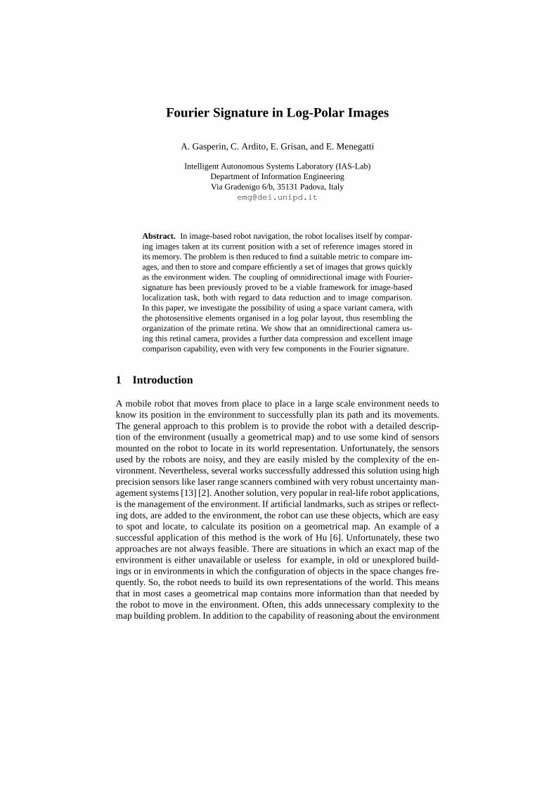
The retina-like sensor used in this work is the Giotto cameradeveloped by Lira-Lab atthe University of Genova [11] [12] and by the Unitek Consortium [4]. It is built usingthe 35µm CMOS technology, and arranging the photosensitive elements in a log-polargeometry. A constant number of elements is placed on concentric rings, so that the sizeof these elements necessarily decreases from the peripherytoward the center. This kindof geometric arrangement has a singularity in the origin, where the element dimensionwould shrink to zero. Since this dimension is constrained bythe building technologyused, there is a ring from which no dimension decrement is possible for accomodat-ing a constant number sensitive elements. Hence, the area inside this limiting ring doesnot show a log-polar geometry in the arrangement of the elements, but is neverthelessdesigned to preserve the polar structure of the sensor and atthe same time tessellatethe area with pixels of the same size. This internal region will be called thefoveaofthe sensor for its analogy with the fovea in the animal retina, whereas the region withconstant number of pixels per ring will be calledperiphery.The periphery is composed byNper = 110 rings withM = 252 pixels each, and the
Fig. 1. The central part of the electronic layout of the retinal sensor (from [4]).
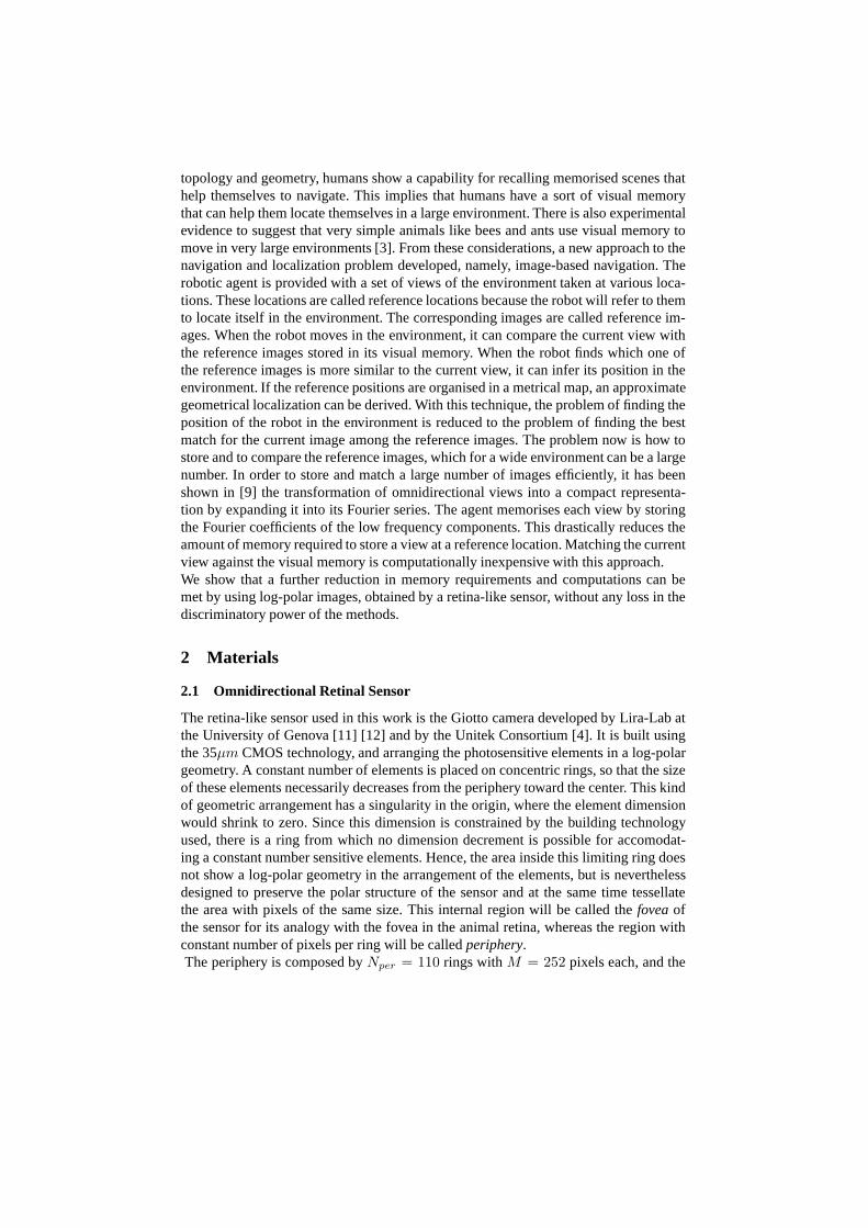
fovea is composed byNfov = 42 rings (see Fig. 1). This lead to a log-polar image hav-ing size ofMxN = 252x152, whereN = (Nper + Nfov), and the image is obtainedfrom a sensor with 38.304 photosensitive elements. It is claimed in [4] that given itsresolution, the log polar sensor yields an image equivalentto a1090x1090 image ac-quired with a usual CCD: a sample image acquired with this camera is shown in Fig. 2,together with its cartesianig:retina remapping in Fig. 3
Fig. 2. A sample252x152 image acquiredwith the retina-like camera.
Fig. 3. The sample image of Fig. 2 trans-formed in a1090x1090 cartesian image.
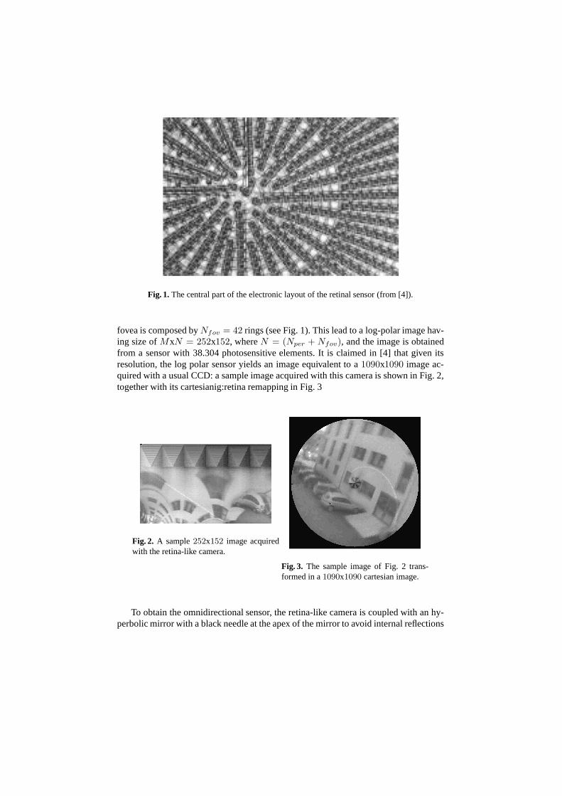
To obtain the omnidirectional sensor, the retina-like camera is coupled with an hy-perbolic mirror with a black needle at the apex of the mirror to avoid internal reflections
on the glass cylinder [7]: the sensor can be seen in Fig. 4(a).A single omnidirectionalimage gives a360o view of the environment, as can be seen in Fig. 4(b).
(a) (b)
Fig. 4. (a) The omnidirectional sensor composed by the retina-likecamera and the hyperbolicmirror. (b) A sample image acquired with the omnidirectional retinal sensor.
3 Methods
3.1 Log-Polar Omnidirectional Image
The pixel coordinates of the output image of the retinal sensor are polar coordinates(ρ, ϑ), that are related to the usual cartesian coordinates(x, y) via:
ρ = log(
√
x2 + y2)
ϑ = arctan(
y
x
)(1)
There are two main issues to be considered while dealing withlog-polar images. Thefirst is that there is a singularity in the transformation near the origin, where the pixeldimension tend to zero. The transformation can thus be considered exact only in the re-gion outside the fovea, whereas inside the fovea the mappingdepends on the particulararrangement of the retinal sensor.The second point is the consideration that given the sampling in polar coordinates in-duced by the sensor, moving from the center toward the periphery of the image, themapping is not bijective from(ρi, ϑi) → (xi, yi), but rather one point in the log polarimage correspond to a sector of annular ring:
This means that from the center of the image toward its outer boundary, the resolutiondecreases, as a pixel in the log-polar image gather information from a bigger area than
a pixel, e.g., in the fovea.An interesting property of the retinal sensor appears when it is coupled with an hyper-bolic mirror, so to provide an omnidirectional sensor. In fact the space-variant resolutionof the sensor, if matched with the hyperbolic projection provide an omnidirectional im-age of nearly constant resolution. Moreover, the image acquired by this omnidirectionalsensor is already in the form of a panoramic cylinder, without need of further transfor-mations [12, 10].
3.2 Fourier Signature
In image-based navigation the main problem is the storage ofreference images andthe comparison of these images with those acquired during the localization. In [9] wasshown the effectiveness of using a small number of Fourier coefficients to characterizean image: that method both reduce drastically the dimensionof the information to bestored and proved to be enough to discriminate different images, without the need ofimage alignment as in [1] [5] [8].The Fourier signature is computed in two steps. First, we calculate the 1-D Fouriertransform of every line of the log-polar image and we store ina matrix the Fouriercoefficients line by line. Then, we keep only a subset of the Fourier coefficients, thosecorresponding to the lower spatial frequencies, as signature for the image.To fully exploit the further dimensionality reduction imposed by the retina-like sensor,we have to recall that in the fovea the effective physical pixels (and therefore the amountof information) is 1 in the center, that is mapped in first lineof the log-polar image, 4in the second innermost ring, mapped in the second line, and so on until the numberof pixels in the ring match that of the periphery, where the amount of pixels per ring isconstant. A number of physical pixels smaller than the number of image pixels inducesa smaller band on the signal than it would be possible given the image dimension.This leads to the consideration that in the foveal region we need to retain less Fouriercoefficients than in the periphery to achieve a storage efficiency without loosing anyinformation. The choice is therefore to decrease linearly the number of coefficientsused to build the signature: from thekmax per line in the periphery (rowsNfov + 1 toN in the log-polar image), to the 1 coefficient of the first line of the image. Hence forthe rowy:
k(y) =
{
⌈kmax−1Nfov−1 · y +
kmax−Nfov
kmax−1 ⌉ if y ≤ Nfov
kmax if y > Nfov
(3)
with ⌈x⌉ meaning the ceiling ofx.
3.3 Dissimilarity measure
Given an imageI, and the discrete set of its Fourier coefficients for the liney, ay,k,with y = 1, . . . , N , we can define the Fourier signature as the vectorF containing thejuxtaposition of all Fourier coefficients of the signature for each line:
A distance between two imagesIi andIj can be evaluated as theL1 norm between thetwo vectors of their Fourier signature:
d(Ii, Ij) = |F(Ii) − F(Ii)|1 (5)
When a database of images is available, and a new image have tobe compared withthose in the database to find the best match, is often more intuitive to use a measure ofrelative distance of the image under examination from one inthe database, given all theimages in the database:
p(Ii, Ij) = 1 −d(Ii, Ij)
maxi,j(d(Ii, Ij))(6)
This is a normalized distance in the database, assuming values in the interval[0, 1], andcan therefore be viewed as a probabilitya posterioriof an imageIi to be equal to imageIj , with j = 1, . . . , N , and N the number of images in the database.
4 Results and Discussion
To test the proposed measure, an image database was built by acquiring a frame fromdifferent positions in an indoor environment, using the retinal omnidirectional cameradescribed previously. The acquisition sites were 15 locations 20cm apart.First of all, we made experimentations to evaluate which is the minimum number ofFourier coefficients necessary to construct a Fourier signature that retains all and onlythe necessary information. Hence, we calculated the similarity of each input imageagainst all the reference image of the dataset varying the number of coefficients per row(kmax) of the Fourier signature. Since the Nyquist frequency of each row isfNy = N
2 ,the maximum number of coefficients of the DFT which yield effective information isN2 . Therefore, we madekmax ∈ K = [1, . . . , N
2 ].
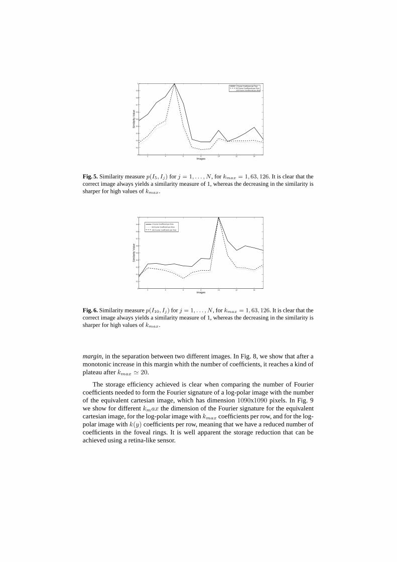
For eachkmax ∈ K we first evaluated the similarity measure Eq. (6) of each imagein the reference database from every other image in the reference database. By thismean, we show that Eq. (6) is an effective measure to distinguish different images, andcan therefore be used to provide a good localization performance in autonomous robotnavigation tasks. In Fig. 7 we show three successive sample images (relative distanceequal to 15cm) from the reference database, and the similarity value of an input imagetaken at a location corresponding to the second reference image. The similarity valueyields a correct match between input and reference.
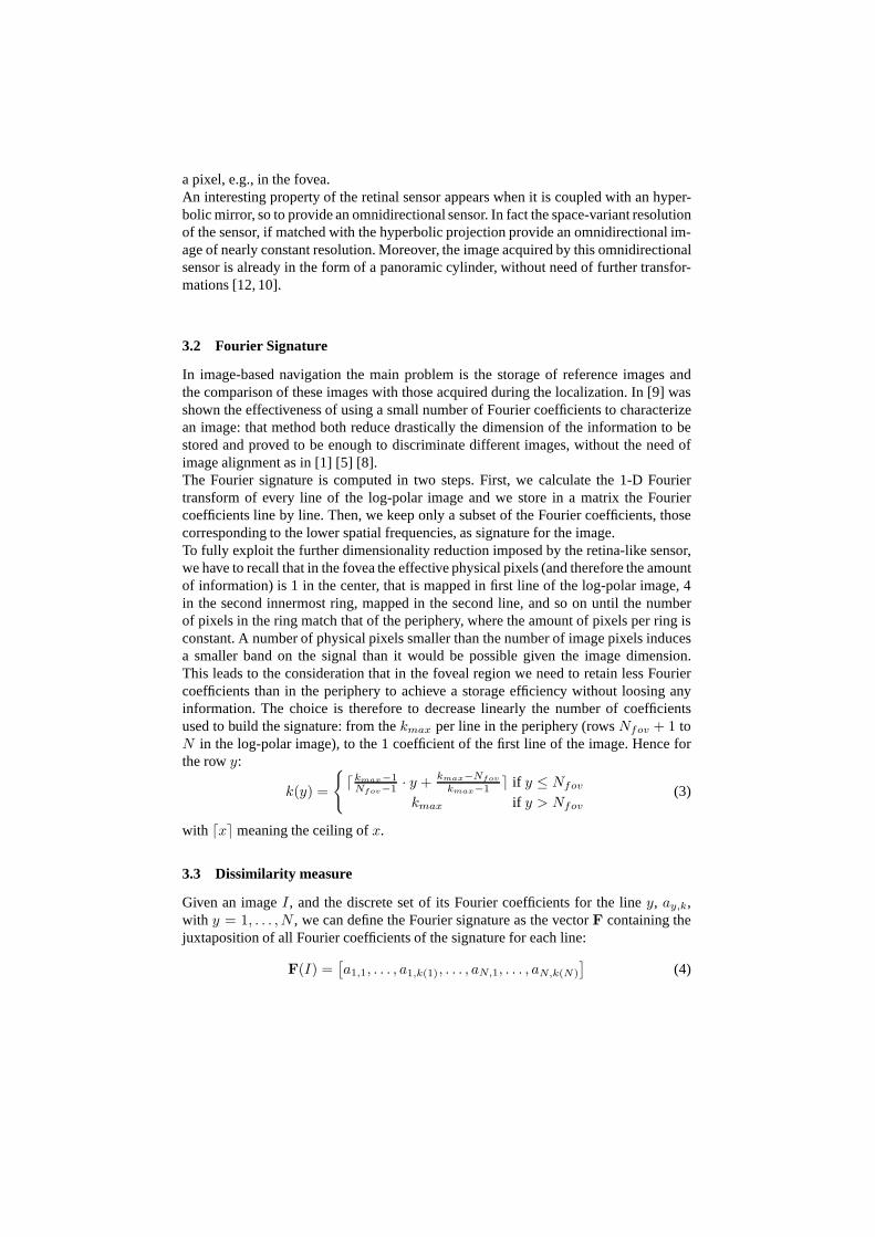
In Fig. 5 and Fig. 6, it is shown the values of the similarity value for different valuesof kmax of an image in the reference database with every other image.In both figures,the similarity peak corresponds to the correct image, and the similarity values decreasearound the peak, the higherkmax, the sharper the decrease.The choice ofkmax influences the trade off between dissimilarity accuracy andimagestorage efficiency. A good measure of the accuracy of the proposed measure is the mini-mum difference between1−d(Ii, Ij) for i 6= j. This is equivalent to evaluate aclassifier
2 4 6 8 10 12 140
0.1
0.2
0.3
0.4
0.5
0.6
0.7
0.8
0.9
1
Images
Sim
ilarit
y V
alue
1 Fourier Coefficient per Row63 Fourier Coefficients per Row126 Fourier Coefficients per Row
Fig. 5. Similarity measurep(I5, Ij) for j = 1, . . . , N , for kmax = 1, 63, 126. It is clear that thecorrect image always yields a similarity measure of 1, whereas the decreasing in the similarity issharper for high values ofkmax.
2 4 6 8 10 12 140
0.1
0.2
0.3
0.4
0.5
0.6
0.7
0.8
0.9
1
Images
Sim
ilarit
y V
alue
1 Fourier Coefficient per Row
63 Fourier Coefficient per Row
126 Fourier Coefficients per Row
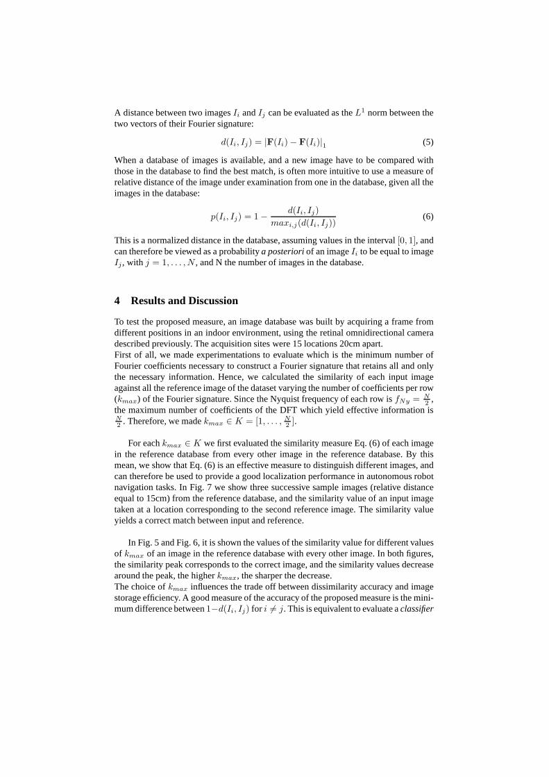
Fig. 6. Similarity measurep(I10, Ij) for j = 1, . . . , N , for kmax = 1, 63, 126. It is clear that thecorrect image always yields a similarity measure of 1, whereas the decreasing in the similarity issharper for high values ofkmax.
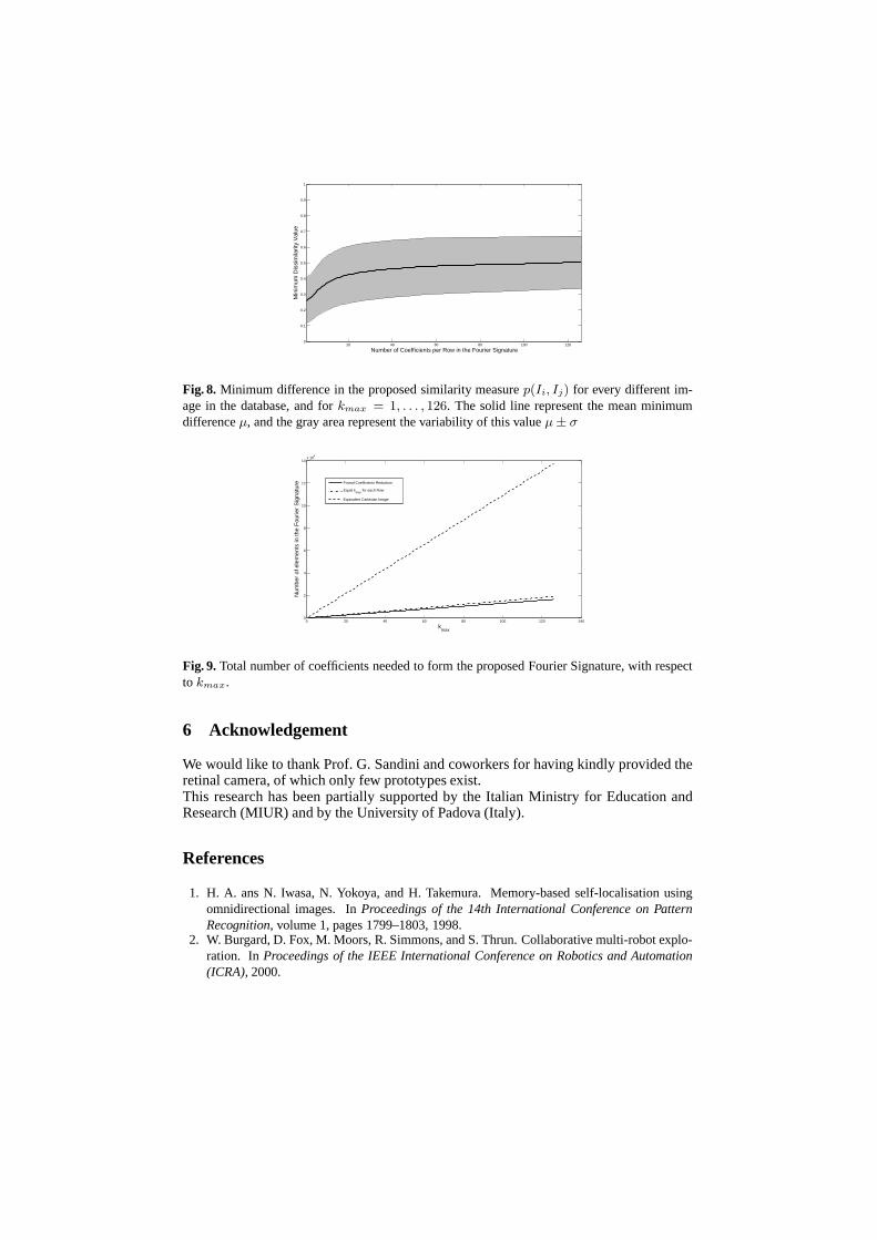
margin, in the separation between two different images. In Fig. 8, we show that after amonotonic increase in this margin whith the number of coefficients, it reaches a kind ofplateau afterkmax ≃ 20.
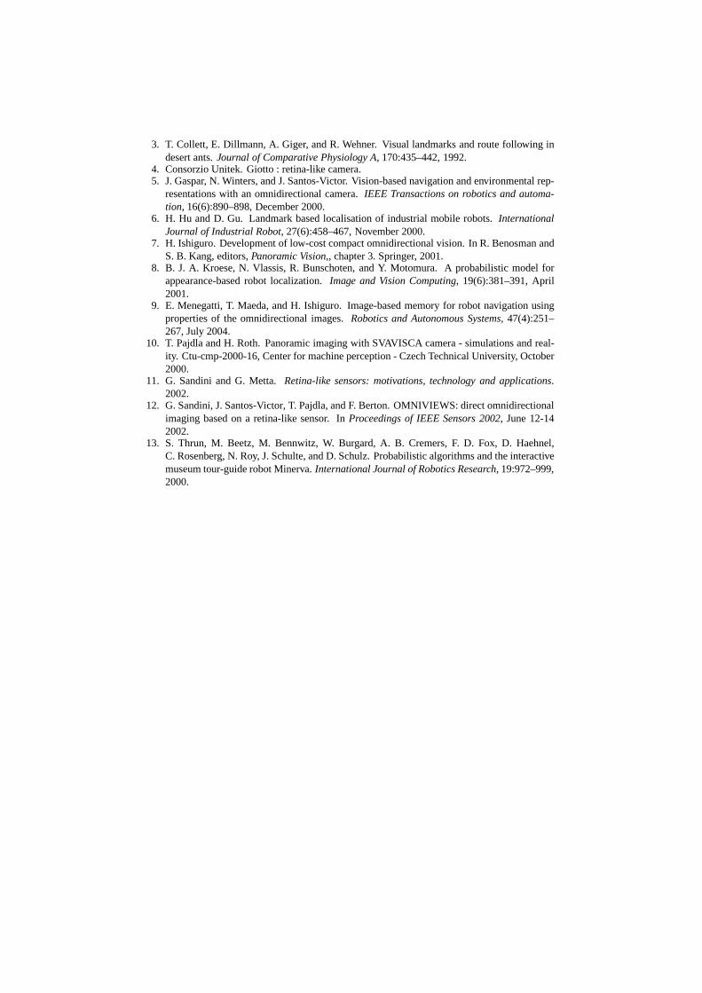
The storage efficiency achieved is clear when comparing the number of Fouriercoefficients needed to form the Fourier signature of a log-polar image with the numberof the equivalent cartesian image, which has dimension1090x1090 pixels. In Fig. 9we show for differentkmax the dimension of the Fourier signature for the equivalentcartesian image, for the log-polar image withkmax coefficients per row, and for the log-polar image withk(y) coefficients per row, meaning that we have a reduced number ofcoefficients in the foveal rings. It is well apparent the storage reduction that can beachieved using a retina-like sensor.
(a) Reference Image 1 (b) Reference Image 2
(c) Reference Image 3 (d) Input Image
Fig. 7. Three reference image taken 15 cm apart, to be confronted with an input image acquiredat location (b). Withkmax = 10, the similarity value of the input image with image (a) is 0.59,with (b) is 0.96, and with (c) is 0.54: the correct match has the highest similarity value.
5 Conclusions
In this paper we show that retinal omnidirectional images can be successfully used tolocalize an autonomous robot with the image-based navigation approach. Within thisapproach, the direct comparison of images is not robust, is too computationally cum-bersome, and the storage of the whole images requires an excessive memory space.Representing the images with their Fourier signature has been proved a viable way toovercome these problems. In this paper, we showed that coupling this technique withlog-polar sensor yields a further dimensionality reduction with sufficient accuracy.The reduction is achieved by exploiting the different bandwidth of each ring of theretina-like sensor with respect to the constant bandwidth of a cartesian sensor, whereeach row contains the same number of photosensitive element. This allows to keep adecreasing number of Fourier coefficients in the signature,moving from the peripherytoward the center of the sensor.Despite the storage requirement reduction, we show that using a simpleL1 norm ondifference of signature vectors have an excellent discriminatory power in distinguish-ing images taken at different sites.
20 40 60 80 100 1200
0.1
0.2
0.3
0.4
0.5
0.6
0.7
0.8
0.9
1
Number of Coefficients per Row in the Fourier Signature
Min
imum
Dis
sim
ilarit
y V
alue
Fig. 8. Minimum difference in the proposed similarity measurep(Ii, Ij) for every different im-age in the database, and forkmax = 1, . . . , 126. The solid line represent the mean minimumdifferenceµ, and the gray area represent the variability of this valueµ± σ
0 20 40 60 80 100 120 1400
2
4
6
8
10
12
14x 10
4
kmax
Num
ber
of e
lem
ents
in th
e F
ourie
r S
igna
ture Foveal Coefficients Reduction
Equal kmax
for each Row
Equivalent Cartesian Image
Fig. 9. Total number of coefficients needed to form the proposed Fourier Signature, with respectto kmax.
6 Acknowledgement
We would like to thank Prof. G. Sandini and coworkers for having kindly provided theretinal camera, of which only few prototypes exist.This research has been partially supported by the Italian Ministry for Education andResearch (MIUR) and by the University of Padova (Italy).
References
1. H. A. ans N. Iwasa, N. Yokoya, and H. Takemura. Memory-based self-localisation usingomnidirectional images. InProceedings of the 14th International Conference on PatternRecognition, volume 1, pages 1799–1803, 1998.
2. W. Burgard, D. Fox, M. Moors, R. Simmons, and S. Thrun. Collaborative multi-robot explo-ration. InProceedings of the IEEE International Conference on Robotics and Automation(ICRA), 2000.
3. T. Collett, E. Dillmann, A. Giger, and R. Wehner. Visual landmarks and route following indesert ants.Journal of Comparative Physiology A, 170:435–442, 1992.
4. Consorzio Unitek. Giotto : retina-like camera.5. J. Gaspar, N. Winters, and J. Santos-Victor. Vision-based navigation and environmental rep-
resentations with an omnidirectional camera.IEEE Transactions on robotics and automa-tion, 16(6):890–898, December 2000.
6. H. Hu and D. Gu. Landmark based localisation of industrialmobile robots. InternationalJournal of Industrial Robot, 27(6):458–467, November 2000.
7. H. Ishiguro. Development of low-cost compact omnidirectional vision. In R. Benosman andS. B. Kang, editors,Panoramic Vision,, chapter 3. Springer, 2001.
8. B. J. A. Kroese, N. Vlassis, R. Bunschoten, and Y. Motomura. A probabilistic model forappearance-based robot localization.Image and Vision Computing, 19(6):381–391, April2001.
9. E. Menegatti, T. Maeda, and H. Ishiguro. Image-based memory for robot navigation usingproperties of the omnidirectional images.Robotics and Autonomous Systems, 47(4):251–267, July 2004.
10. T. Pajdla and H. Roth. Panoramic imaging with SVAVISCA camera - simulations and real-ity. Ctu-cmp-2000-16, Center for machine perception - Czech Technical University, October2000.
11. G. Sandini and G. Metta.Retina-like sensors: motivations, technology and applications.2002.
12. G. Sandini, J. Santos-Victor, T. Pajdla, and F. Berton. OMNIVIEWS: direct omnidirectionalimaging based on a retina-like sensor. InProceedings of IEEE Sensors 2002, June 12-142002.
13. S. Thrun, M. Beetz, M. Bennwitz, W. Burgard, A. B. Cremers, F. D. Fox, D. Haehnel,C. Rosenberg, N. Roy, J. Schulte, and D. Schulz. Probabilistic algorithms and the interactivemuseum tour-guide robot Minerva.International Journal of Robotics Research, 19:972–999,2000.


![Reminder Fourier Basis: t [0,1] nZnZ Fourier Series: Fourier Coefficient:](https://static.documents.pub/doc/80x56/56649d395503460f94a13929/reminder-fourier-basis-t-01-nznz-fourier-series-fourier-coefficient.jpg)


