135
Non-Proprietary Version

Non-ProprietaryVersion
PSNN-2014-0869.US Safety-related
Docum ent No. j FPG-RQS-C5 1-000 1 Rev 7
The use of the information contained in this document b)snyone for any purpose other than that for which it is intended i,not authorized. In the event the information is used withoniauthorization from TOSHIBA CORPORATION, TOSHIBACORPORATION makes no representation or warranty andsassumes no liability as to the completeness, accuracy, oiusefulness of the information contained in this document.
TOSHIBA CORPORATIONNUCLEAR ENERGY SYSTEMS & SERVICES DIV.
NRW-FPGA-Based PRM System Qualification Project
Document Title Eciuipment Reauirement Specification of FPGA based Units
CUSTOMER NAME NonePROJECT NAME NRW-FPGA-Based PRM
_____________-System Qualification ProjectITEM NAME PRM EquipmentITEM NO. C51JOB NO. FPG
TOSHIBA NED verified this Design Document;Method:" Design VerificationVerification Report No.: • VI? Thi•- 2 ooYo o•
Verifed by
Group Name: Monitorin2 System Enzineerin• Groun
Date /Am-i/ -o, 2-Voo•
TOSHIBA CORPORATION Nuclear Energy Systems & Services Division
1/134

FPG-RQS-C51 -0001 Rev.7
Approved Reviewed Prepared
Rev No. Date History by by by
0 May.31.2005 The first issue N.Oda Y.Goto T.Miyazald
1 June.24.2005 Error correction and description review N.Oda Y.Goto T.Miyazaki
2 Nov.2 2005 E7rror correction and description review N.Oda Y.Goto T.Miyazaki
3 Jan.10.2006 Error correction and description review N.Oda Y.Goto T.Miyazaki
4 Mar.24, 06 Error correction and description review N.Oda Y.Goto T.Miyazaki
5 Jun. 1, 06 Description review N.Oda Y.Goto T.Miyazald
6 Feb. 16, 07 Description review N.Oda Y.Goto T.Miyazaki
7 : 1 t 2."IO, 60o Error correction and description review N.Oda Y.Goto T.Miyazaki
TOSHIBA CORPORATION Nuclear Energy Systems & Services Division
2/134
FPG-RQS-C51 -0001 Rev.7
Table of Contents
1. Scope ........................................................................................ 7
2. Applicable Documents...................................................................... 7
2.1. Supporting and Supplemental Documents .......................................... 7
2.1.1. Supporting Documents .......................................................... 7
3. Applicable Regulations, Codes and Standards .......................................... 8
3.1. Applicable Documents................................................................ 8
3.1.1. Electric Power Research Institute (EPRI).......................................
3.1.2. Institute of Electrical & Electronics Engineers (IEEE)....................... 8
3.1.3. Other Documents ................................................................ 9
3.2. Information Documents............................................................. 10
3.2.1. U.S. Nuclear Regulatory Commission (NRC) Regulatory Guides (RG) .. 10
3.2.2. Other Documents ............................................................... 11
4. System Overview ......................................................................... 12
4.1. Functions ............................................................................. 124.1.1. Design Basis Event.... ......................................................... 12
4.1.2. Safety-related Functions ....................................................... 13
4.1.3. Non Safety-related Functions ................................................. 13
4.2. Summary System Description...................................................... 13
4.3. Detailed System Description ....................................................... 14
4.3.1. System Equipment, Arrangement and Location ............................. 14
4.3.2. Safety Features.................................................................. 20
4.3.3. System Availability............................................................. 21
4.3.4. Environmental Consideration ................................................. 21
4.3.5. Maintenance Provisions........................................................ 21
4.3.6. Self-Testing ..................................................................... 22
4.3.7. Surveillance Testing ........................................................... 22
4.4. Operation............................................................................. 22
4.4.1. Operation........................................................................ 22
4.4.2. Operating Bypasses ............................................................ 22
4.4.3. Calibration ....................................................................... 22
4.4.4. Unit and Detector Bypass...................................................... 23
4.5. System Interface..................................................................... 24
4.5.1. Reactor Manual Control System (RMCS).................................... 24
4.5.2. Reactor Protection System (RPS) ............................................. 24
TOSHIBA CORPORATION Nuclear Energy Systems & Services Division
3/134

FPG-RQS-C51 -0001 Rev.7
4.5.3. Process Computer System (PCS).............................................. 24
4.5.4. Oscillation Power Range Monitor (OPRM)................................... 25
4.5.5. Main Operator Console (MOC) ............................................... 25
4.5.6. Annunciator (ANN) ............................................................ 26
4.5.7. Recorder ......................................................................... 26
5. Design Requirements..................................................................... 28
5.1. Functional Requirements ...................................... •....28
5.1.1. Basic Design Requirements.................................................... 28
5.1.2. System Initialization Requirements........................................... 28
5.1.3. Nominal System Setpoints..................................................... 29
5.1.4. Drift and Accuracy Requirements............................................. 35
5.1.5. Instrument Modes .............................................................. 36
5.1.6. Failure Detection and Self Test Requirements ............................... 38
5.1.7. Availability/Reliability Requirements ........................................ 39
5.1.8. Test Circuit Requirements ..................................................... 40
5.2. Hardware Requirements ............................................................ 40
5.2.1. Unit Configuration Requirements............................................. 40
5.2.2. Unit Input/Output Requirements.............................................. 41
5.2.3. Module Requirements.......................................................... 52
5.2.4. General Design ................................................................. 64
5.3 Software Requirements.............................................................. 66
5.4 Design Life........................................................................... 67
5.5 Environmental Conditions .......................................................... 69
5.5.1 Environmental Requirements ................................................. 69
5.5.2 Seismic Requirements ......................................................... 71
5.5.3 EMJI/RH Requirements ........................................................ 72
5.5.4 Surge Withstand Capability Requirements................................... 77
5.5.5 EFT/B Withstand Requirements .............................................. 78
5.5.6 ESD Withstand Requirements................................................. 79
5.5.7 Isolation Requirements......................................................... 80
5.5.8 Power Supply....................................... :............................ 80
5.5.9 (delete)........................................................................... 80
5.6 Classification ........................................................................ 80
5.7 (Delete)............................................................................... 81
5.8 Maintenance Requirements......................................................... 81
5.9 Design Method........................................................................ 81
TOSHIBA CORPORATION Nuclear Energy Systems & Services Division
4/134
FPG-RQS-051 -0001 Rev.7
5.10 Material requirements ............................................................ 815.11 Requirements for Third P~arty/Sub-Vendor Items................................. 81
6 Fabrication Requirements................................................................ 81
7 Test Requirements ......................... .............................................. 83
7.1 Unit and Module Test ............................................................... 83
7.2 Nre-Qualification Test Requirements............................................... 83
7.2.1 System Test......................................................................... 84
7.2.2 Operability Test Requirements ................................................... 85
7.2.3 Prudency Test Requirements...................................................... 86
7.2.4 Operability and Prudency Test Applicability.................................... 87
7.3 Qualification Tests................................................................... 87
7.3.1 Test Specimen Requirements ..................................................... 88
7.3.2 Qualification Tests and Analysis requirements.................................. 89
7.3.3 Requirements for Compliance to Specifications................................ 92
8 Packaging and Shipping ................................................................. 92
8.1 Packaging Requirements............................................................... 93
8.2 Shipping Requirements.............................................................. 93
8.3 Storage Requirements ............................................................... 93
9 Documentation Requirements........................................................... 94
9.1 Equipment Documentation Requirements......................................... 94
9.1.1 Equipment General Overview Documentation............................... 94
9.1.2 (Deleted)......................................................................... 94
9.1.3 Users Manual ................................................................... 94
9.2 Final Documentation Requirements ............................................... 95
9.2.1 Programmatic Documentation................................................. 95
9.2.2 Technical Items ................................................................. 96
9.2.3 Application Guide .............................................................. 96
9.2.4 Supporting Analyses Documentation......................................... 97
9.2.5 V&V Documentation..... ...................................................... 97
9.2.6 Test System Description ....................................................... 97
9.2.7 Critical Characteristics....................."..................................... 98
9.2.8 Test System Drawing ............................................................ 98
9.2.9 System Software/Hardware Configuration Document ...................... 98
9.2.10 System Setup/Calibration/Checkout Procedure.............................. 98
9.2.11 System Test Documentation................................................... 98
10 Abbreviations ............................................................................. 99
TOSHIBA CORPORATION Nuclear Energy Systems & Services Division
5/134

FPG-RQS-C51 -0001 Rev.7
Attachment A-l1: Compliance and Traceability Matrix of Chapter 4 with IEEE Std603-1991
Attachment A-2: Compliance and Traceability Matrix of Chapter 4 with IEEE Std
7-4.3.2-1993
Attachment B: Compliance and Traceability Matrix of Units Level Requirements with
EPRI TR- 107330 and System Level Requirements
TOSHIBA CORPORATION Nuclear Energy Systems & Services Division
6/134
FPG-RQS-C51 -0001 Rev.7
1. ScopeThis document describes the equipment requirements of the Non Rewritable(NRW)-Field Programmable Gate Array (FPGA) based units for the Power RangeMonitor (PRM).
The equipment requirements consist of specific functional and design requirements ofthe hardware and FPGA logic, including any detailed logic requirements. TheEquipment Requirements Specification (ERS) also specifies qualification requirements.
This ERS is prepared specifically for the NRW-FPGA-Based PRM SystemQualification Project.
The scope of the PRM System described in this specification includes units performingthe functions of the LPRM, APRM and flow measurement, plus the interconnectingcables between units. The scope does not include requirements for external interfacingcomponents such as the in-core detectors and differential pressure transmitters.
2. Applicable Documents2.1. Supporting and Supplemental Documents2.1.1. Supporting Documents
The latest revision is applicable about following documents.
2.1.1.1. EPRI TR-107330Generic Requirements Specification for Qualifying a Commercially AvailablePLC for Safety-Related Applications in Nuclear Power Plants
2.1.1.2. RS-5114010PRM System Design Specification for Japanese Plants
2.1.1.3. FPGA-based PRM Unit Equipment Design Specifications (for CommercialProduct):5G8HA385 PRM Unit Equipment Design Specification5G8HA386 LPRM/APRM Unit Design Equipment Specification5G8HA381 Flow Unit Design Equipment Specification
2.1.1.4. FPGA-based PRM Unit Equipment Users Manual (for Commercial Product):6E8H7301 Instructions for TOSDTA LPRM (HNU100)6E8H7302 Instructions for TOSDIA APRM (HNTJ200)6E8H7306 Instructions for TOSDIA FLOW (HNUJ300)
2.1.1.5. FPGA-based PRM Module Equipment Design Specification (forCommercial Product):5G8HA382 SQ-ROOT Module Equipment Design Specification5G8HA390 APRM Module Equipment Design Specification
TOSHIBA CORPORATION Nuclear Energy Systems & Services Division
7/134

FPG-RQS-C51 -0001 Rev.7
5G8HA391 LPRM Module Equipment Design Specification5G8HA393 TRN Module Equipment Design Specification5G8HA394 RCV Module Equipment Design Specification5G8HA395 DIO Module Equipment Design Specification5G8HA396 AO Module Equipment Design Specification5G8HA439 FLOW Module Equipment Design Specification5G8HA466 LVPS Module Equipment Design Specification5G8HA475 STATUS Module Equipment Design Specification
2.1.1.6. FPG-PLN-A70-O0001Project Quality Assurance Manual.
3. Applicable Regulations, Codes and Standards3.1. Applicable Documents3.1.1. Electric Power Research Institute (EPRI)3.1.1.1. TR-102323-R2
Guidelines for Electromagnetic Interference Testing in Power PlantEquipment, November 2000
3.1.1.2. TR-100516Equipment Qualification Reference Manual, November 1992
3.1.1.3. TR-107330Generic Requirements Specification for Qualifying a Commercially AvailablePLC for Safety related Applications in Nuclear Power Plants
3.1 .2. Institute of Electrical & Electronics Engineers (IEEE)3.1.2.1. IEEE Std7-4.3.2-1993
IEEE Standard Criteria for Digital Computers in Safety Systems of NuclearPower Generating Stations
3.1.2.2. IEEE Std 323-1983, Standard for Qualifying of Class 1E Equipment forNuclear Power Generating Stations
3.1.2.3. IEEE Std 344-1987, IEEE Recommended Practice for Seismic Qualificationof Class 1E Equipment for Nuclear Power Generating Stations
3.1.2.4. IEEE Std 379-2000Standard Application of the Single-Failure Criterion to Nuclear PowerGenerating Station Safety Systems
3.1.2.5. IEEE Std 383-1974IEEE Standard for Type Test of Class lE Electric Cables, Field Splices, andConnections for Nuclear Power Generating Stations
3.1.2.6. IEEE Std 384-1992IEEE Standard Criteria for Independence of Class lE Equipment and Circuits
3.1.2.7. IEEE Std 603-1991
TOSHIBA CORPORATION Nuclear Energy Systems & Services Division
8/134
FPG-RQS-C51 -0001 Rev.7
IEEE Standard for Safety Systems for Nuclear Power Generating Stations3.1.2.8. IEEE Std 730-2002
IEEE Standard for Software Quality Assurance Plans
3.1.2.9. IEEE Std 828-1990Standard for Software Configuration Management Plans
3.1.2.10. IEEE Std 1012-1998Standard for Software Verification and Validation Plans
3.1.2.11. IEEE Std 1074-1995IEEE Standard for Developing Software Life Cycle Processes
3.1.2.12. IEEE Std 352-1987Guide for General Principles of Reliability Analysis of Nuclear PowerGenerating Stations
3.1.2.13. IEEE Std 1050-1996Guide for Instrumentation Control Equipment Grounding in GeneratingStations
3.1.2.14. IEEE Std 338-1987IEEE Standard Criteria for the Periodic Surveillance Testing of NuclearPower Generating Station Safety System
3.1.2.15. IEEE Std 498-1990IEEE Standard Requirements for the Calibration and Control of Measuringand Test Equipment Used in Nuclear Facilities
3.1.3. Other Documents3.1.3.1. ISA-$67.04-1994
Setpoints for Nuclear Safety related Instrumentation Used in Nuclear PowerPlants
3.1.3.2. ANSI,N45.2.2-1982Packing, Shipping, Receiving, Storage and Handling of Items for NuclearPower Plants
3.1..3.3. MIL-I-DfBK 217FReliability Prediction of Electronic Equipment
3.1.3.4. MIL-STD-461ERequirements for the Control of Electromagnetic Interference Characteristicsof Subsystems and Equipment
3.1.3.5. IEC61000-4-2-1995Testing and measurement requirement techniques-Section 2: Electrostaticdischarge immunity test
3.1.3.6. IEC61000-4-4-1995Testing and measurement requirement techniques-Section 4:Electrical fasttransient/burst immunity test
3.1.3.7. IEC61000-4-5-1995
TOSHIBA CORPORATION Nuclear Energy Systems & Services Division
9/134

FPG-RQS-C51 -0001 Rev.7
Testing and measurement techniques-Section 5: Surge immunity test3.1.3.8. IIEC61000-4-12-1995
Testing and measurement techniques-Section 5: Oscillatory waves immunitytest, Basic EMC publication
3.1.3.9. Toshiba 440 1-4"Nuclear Energy QA Program Description" Rev. 1.
3.2. Information Documents3.2.1. U.S. Nuclear Regulatory Commission (NRC) RegulatoryGuides (RG)3.2.1.1. RG 1.22, Feb. 1972
Periodic Testing of Protection System Actuation Functions
3.2.1.2. RG 1.29, Rev 3, Sep. 1978Seismic Design Classification
3.2.1.3. RG 1.47, Rev 0, May. 1973Bypassed and Inoperable Status Indication for Nuclear Power Plant SafetySystems
3.2.1.4. RG 1.53,Rev 2, Nov. 2003Application of the Single-Failure Criterion to Nuclear Power Plant ProtectionSystems
3.2.1.5. RG 1.75,Rev 2, Sep. 1978Physical Independence of Electric Systems
3.2.1.6. RG 1.89, Rev l, Jun. 1984Environmental Qualification of Certain Electric Equipment Important toSafety for Nuclear Power Plants
3.2.1.7. RG 1.152, Rev 1, Jan. 1996Criteria for Programmable Digital Computer System Software in Safetyrelated Systems of Nuclear Power Plants
3.2.1.8. RG 1.153, Rev1, Jun. 1996Criteria for Safety Systems
3.2.1.9. RG 1.168, Rev.1, Feb. 2004Verification, Validation, Reviews and Audits for Digital Computer SoftwareUsed in Safety Systems of Nuclear Power Plants
3.2.1.10. RG 1.169, Sept 1997Configuration Management Plans for Digital Computer Software Used inSafety Systems of Nuclear Power Plants
3.2.1.11. RG 1.170, Sep. 1997Software Test Documentation for Digital Computer Software Used in SafetySystems of Nuclear Power Plants
3.2.1.12. RG 1.171, Sep. 1997Software Unit Testing for Digital Computer Software Used in Safety Systems
TOSHIBA CORPORATION Nuclear Energy Systems & Services Division
10/134

FPG-RQS-C51 -0001 Rev.7
of Nuclear Power Plants3.2.1.13. RG 1.172, Sep. 1997
Software Requirements Specifications for Digital Computer Software Used inSafety Systems of Nuclear Power Plants
3.2.1.14. RG 1.173, Sep. 1997Developing Software Life Cycle Processes for Digital Computer SoftwareUsed in Safety Systems of Nuclear Power Plants
3.2.1.15. RG 1.180 Rev 1, Oct. 2003Guidelines for Evaluating Electromagnetic and Radio-Frequency Interferencein Safety related Instrumentation and Control Systems
3.2.1.16. RG 1.100 Rev2, Jan. 1988Seismic Qualification of Electric Equipment for Nuclear Power Plants
3.2.2.3.2.2.1.
Other DocumentsNURiEG-0800Standard Review Plan for the Safety Analysis Reports for Nuclear PowerPlants
TOSHIBA CORPORATION Nuclear Energy Systems & Services Division
11/134
FPG-RQS-C51 -0001 Rev.7
4. System OverviewThis section describes the PRM System applied for existing typical US BWR nuclearpower plants having following system features:
• Input signal froml72 LPRM Detectors.* Six APRM channels, two LPRM channels.• Two RBM channels and four Flow channels.* The Reactor Protection System (RPS) logic is one out of two taken twice for
Locking Piston CRD system.* Interconnection to an OPRM System (a protection system for reactor power
oscillation).
Requirements for this system are obtained from the following sources:
a EPRI TR-107330* PRM System Design Specification for Japanese Nuclear Plant• IEEE Std 603-1991 and IEEE Std 7-4.3.2-1993
Section 5 of this document provides detailed design requirements for the units andinterfacing cables that make up the test specimen for the qualification project.
Requirements from the Japanese Nuclear Plant System Design Specification, and fromthe IEEE standards, are summarized in Section 4 of this ERS.
Compliance traceability matrixes are provided in Appendix A-i and A-2 to this ERS.These matrixes show how the requirements of IEEE Std 603-1991 and IEEE Std7-4.3.2-1993 are addressed in Section 4 of this ERS.
4.1. Functions4.1.1. Design Basis Event
Following design basis events that require safety functions of the PRM Systemspecified in Section 4.1.2 are postulated:
* Anticipated Operational Occurrences whose result might occur to exceed[ acceptable fuel design limits, specified in NUJREG-0800 Chapter 15* Plant Design Basis Accidents specified in NUREG-0800 Chapter 15* Reactor Power Oscillation specified in NUREG-0 800 Chapter 15.9
For design basis events, the postulated initial condition of these events is that reactorpower is at 100 % rated power plus power measurement uncertainty.
TOSHIBA CORPORATION Nuclear Energy Systems & Services Division
12/134
FPG-RQS-C51 -0001 Rev.7
4.1.2. Safety-related Functions
The PRM has the following safety-related functions:
1. Generate signals that represent:a. Local neutron fluxb. Spatially averaged neutron fluxc. Spatially averaged heat flux (Simulated Thermal Power Level)d. Recirculation flow
2. Proiide the following trips to the Reactor Protection System (RPS) - DivisionalAPRM trips shall be initiated by any of the following:a. APRM Upscale (High-High) Tripb. Simulated Thermal Power Upscale Tripc. APRM Inoperable Trip
4.1.3. Non Safety-related Functions
The PRM has the following non-safety-related functions:
1. Provide data signals, including recording transient data, and trip indications to theProcess Computer.
2. Provide a rod withdrawal block signal to the Reactor Manual Control System(RMCS), if any one of the following occurs:
a. APRM Upscale (High) Tripb. APRM Inoperable Tripc. APRM Downscale Tripd. Recirculation Flow Upscale / Inoperable Tripe. RBM upscale Tripf. RBM downscale Tripg. RBM Inoperable Triph. Recirculation Flow comparison Abnormal Trip
4.2. Summary System Description
The PRM is designed to provide information used for monitoring the average powerlevel of the reactor core, monitoring the local power density distribution associated withthe withdrawal or insertion of a control rod, and for protecting the core against local andfull-core power transients when the reactor power is in the power range, i.e., aboveapproximately 10 percent of rated power. It provides trip signals to initiate reactorscrams under excessive neutron flux conditions or fast increasing neutron fluxconditions. It provides alarms to the operator warning of the impending and actualoccurrence of these trips. It also provides power information to the operator andpefforms the rod block monitoring function.
TOSHIBA CORPORATION Nuclear Energy Systems & Services Division
13/134
FPG-RQS-C51 -0001 Rev.7
The PRM has following subsystems:
a. Local Power Range Monitor (LPRM) Subsystemb. Average Power Range Monitor (APRM) Subsystemc. Recirculation Flow Measurement Subsystemd. Rod Block Monitor (RBM) Subsystem
The LPRM Subsystem continuously monitors the local neutron flux distribution in thecore. In the PRM System considered in this project, the LPRM subsystem contains 172neutron detectors distributed throughout the reactor core. The LPRM Subsystemprovides LPRM levels indication and reading of this information to other systems foroperation and control. It also provides alarms when preset levels are reached. TheLPRM detectors provide measurement of core local power from 1% to above 100% ofthe rated power.
The APRM Subsystem provides APRM levels by averaging the output signals from theselected LPRM signal. Typically, the APRM Subsystem consists of six channels. TheLPRM signals are divided and assigned to the APRM channels. The APRM Subsystemissues trip signals for generating reactor trip and alarn functions.
Signals from the Recirculation Flow Measurement Subsystem are available for theAPRM Subsystem and RBM trip setpoint determination.
The LPRM, APRM and Recirculation Flow signals are displayed for operators at the]Main Operator Console (MOC).
The RBM Subsystem is not part of the qualification effort. Therefore, its functions arenot described in this document. However, the interfaces of the LPRM, the APRM andthe Recirculation Flow Measurement Subsystems with the RBM Subsystem aredescribed.
These subsystems include varistors and noise filters in power supply lines of each unitto prevent surge voltage. Specific requirements are described in Section 5.2.4.7.
4.3. Detailed System Description4.3.1. System Equipment, Arrangement and Location
This section provides a detailed explanation of the system configuration of the PRMSystem. Specific requirements for the PRM hardware components are described inSection 5.2.
The LPRM subsystem receives signals from the 43 LPRM detector assemblies, eachwith four fission chamber detectors (i.e. LPRM detectors) evenly spaced at four axialpositions along the fuel bundle in the vertical direction. These are called the A, B, C,and D detectors positions. The assemblies are distributed throughout the whole core inevenly spaced locations such that each assembly is located at every fourth intersection
TOSHIBA CORPORATION Nuclear Energy Systems & Services Division
14/134

FPG-RQS-C51 -0001 Rev.7
of the water channels around fuel bundles not containing a control rod. The LPRMsubsystem also includes cables, electrical penetrations and LPRM signal processing.
Each detector assemblies are housed in and fitted at the incore housing withpenetrations at the bottom of the RPV. "
Each LPRM signal is provided to either an APRM channel or an LPRM channel.
* LPRM detector signals provided to an LPRM channel. The LPRM subsystemconsists of two LPRM channels, one of which is connected to 21 detectors,and the other of which is connected to 22 detectors. The LPRM subsystemfunction is to provide indication and reading of the local neutron fluxinformation to other systems for operation and control. It also provides alarmswhen preset levels are reached.
* LPRM signals provided to an APRM channel. There are six APRM channelsthat monitor the average reactor power. Each APRM channel has twofunctions: the function of LPRM subsystem, as described above; and thefunction of APRM subsystem, to average the selected LPRM signals, providethe average reactor power to other systems for operation and control, andissue trip signals.
The APRM subsystem is designed to include redundancy in order to maintain thesystem safety functions in the event of a single failure.
Each APRM channel (Channel A through F) receives signals from two Flow channels.All flow channels (Channels A through D) are identical in design and independent ofeach other. The assignment of Flow channels to APRM channels is shown below:
Assignment of Flow Channelsto APRM Channels
F'LOW channel A B C D
APRM channel A,C,E B,D,F A,C,E B,D,F
The assignment of the APRM channels to the one out of two taken twice type RPS ispresented below.
TOSHIBA CORPORATION Nuclear Energy Systems & Services Division
15/134
FPG-RQS-C51 -0001 Rev.7
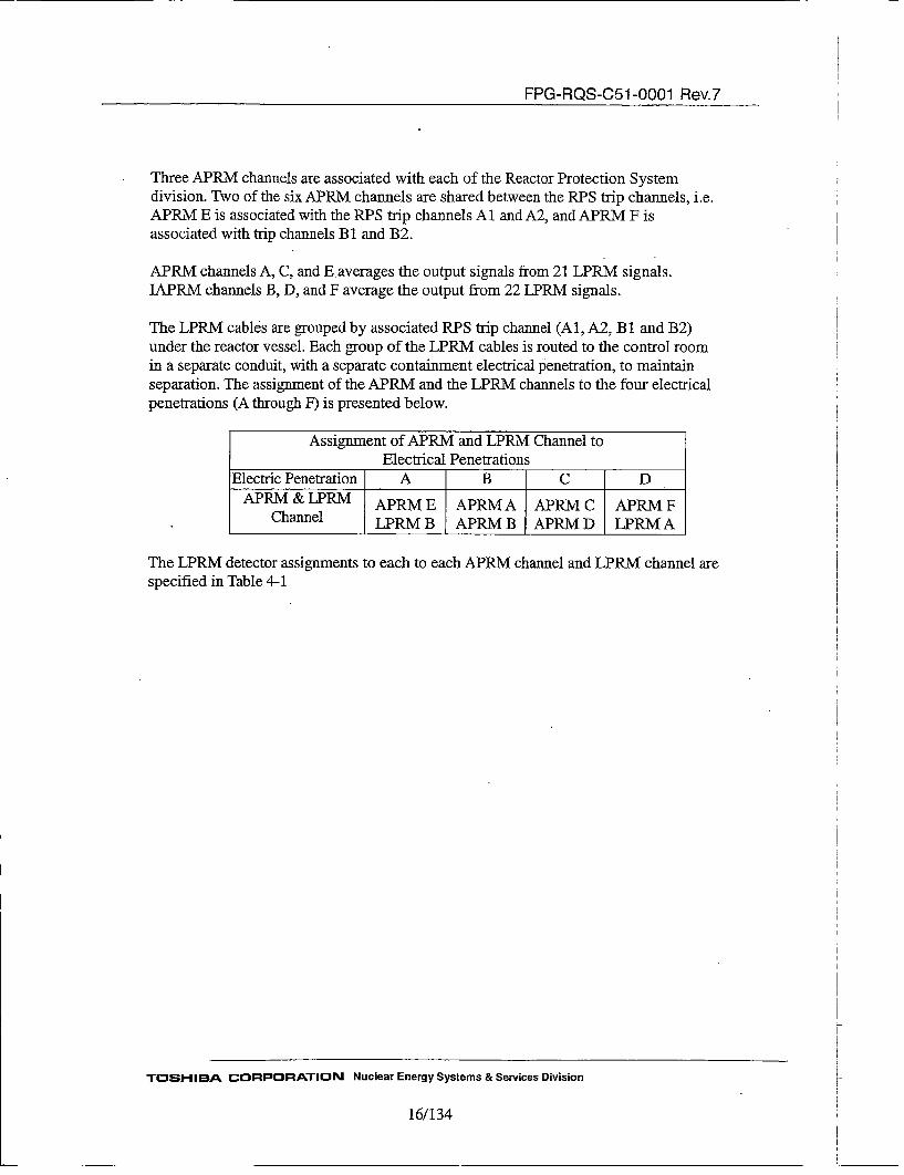
Three APRM channels are associated with each of the Reactor Protection Systemdivision. Two of the six APRM channels are shared between the RPS trip channels, i.e.APRM E is associated with the RPS trip channels Al and A2, and APRM F isassociated with trip channels B 1 and B2.
APRM channels A, C, and E averages the output signals from 21 LPRM signals.IAPRM channels B, D, and F average the output from 22 LPRM signals.
The LPRM cables are grouped by associated RPS trip channel (Al, A2, B1 and B2)under the reactor vessel. Each group of the LPRM cables is routed to the control roomin a separate conduit, with a separate containment electrical penetration, to maintainseparation. The assignment of the APRM and the LPRM channels to the four electricalpenetrations (A through F) is presented below.
Assignment of APRM and LPRM Channel toElectrical Penetrations
Electric Penetration A B C DAPRM & LPRM APRM E APRM A APRM C APRM F
Channel LPRM B APRM B APRM D LPRM A
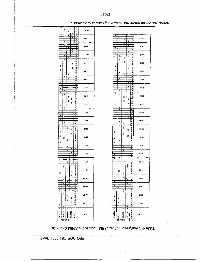
The LPRM detector assignments to each to each APRM channel and LPRM channel arespecified in Table 4-1
TOSHIBA CORPORATION Nuclear Energy Systems & Services Division
16/134
I7TI/LT
.7 uOIsiAIcI seoliues ~ swe~sA~ A5~au~ J9OPflN NOI±V~iOd~OO VUIHSOI
xx
x
xx
x __
xx
xx
xx
x __
xx
7-x
x
-- 7x
xx __
xx
xx
xx
x __
xx
x
xx
xx
xx
x
xx
x
x'C
'C
'C'C
'C __
'C'C
'C'C'C
'C'C
'C'C
'C'C
'C __
'C'C
'C
'C'C
'C __
'C'C
'C'C
7T5 v
~J vJ ~i 40U H U Ud d d d
Y V1ONNVHO
a06Vaa
60V
LL-St'
LL-9L
14'-90
L~0~
14'-90
6t'-Rt'
LS-Ot'
Ls-~
A01I
LOUdl
SIGUUBLj3 IAftIdV eq~ o~ s~nduI IAIUdi GLfl JO ~UeWU5!9SV L-t7 eIqeL
L'^eU 1-000- 1-SO-SOUl-Dd--
FPG-RQS-C51 -0001 Rev.7
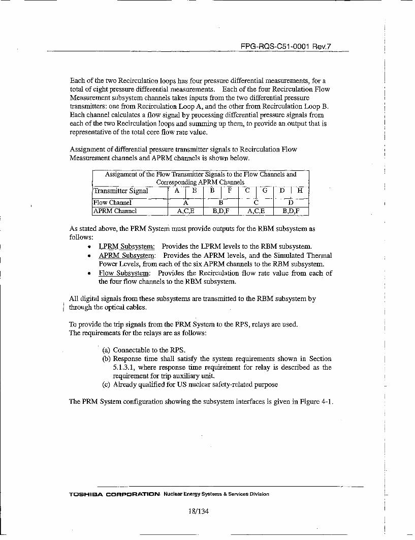
Each of the two Recirculation loops has four pressure differential measurements, for atotal of eight pressure differential measurements. Each of the four Recirculation FlowMeasurement subsystem channels takes inputs from the two differential pressuretransmitters: one from Recirculation Loop A, and the other from Recirculation Loop B.Each channel calculates a flow signal by processing differential pressure signals fromeach of the two Recirculation loops and summing up them, to provide an output that isrepresentative of the total core flow rate value.
Assignment of differential pressure transmitter signals to Recirculation FlowMeasurement channels and APRM channels is shown below.
Assignment of the Flow Transmitter Signals to the Flow Channels andCorresponding APRM Channels
Transmitter Signal A E B F C [G D H
Flow Channel A B C DAPRM Channel A,C,E B,D,F A,C,E B,D,F
As stated above, the PRM System must provide outputs for the RBM subsystem asfollows:
* LPRM Subsystem: Provides the LPRM levels to the RBM subsystem.* APRM Subsystem: Provides the APRM levels, and the Simulated Thermal
Power Levels, from each of the six APRM channels to the RBM subsystem.* Flow Subsystem: Provides the Recirculation flow rate value from each of
the four flow channels to the RBM subsystem.
All digital signals from these subsystems are transmitted to the RBM subsystem bythrough the optical cables.
To provide the trip signals from the PRM System to the RPS, relays are used.The requirements for the relays are as follows:
(a) Connectable to the RPS.(b) Response time shall satisfy the system requirements shown in Section
5.1.3.1, where response time requiremaent for relay is described as therequirement for trip auxiliary unit.
(c) Already qualified for US nuclear safety-related purpose
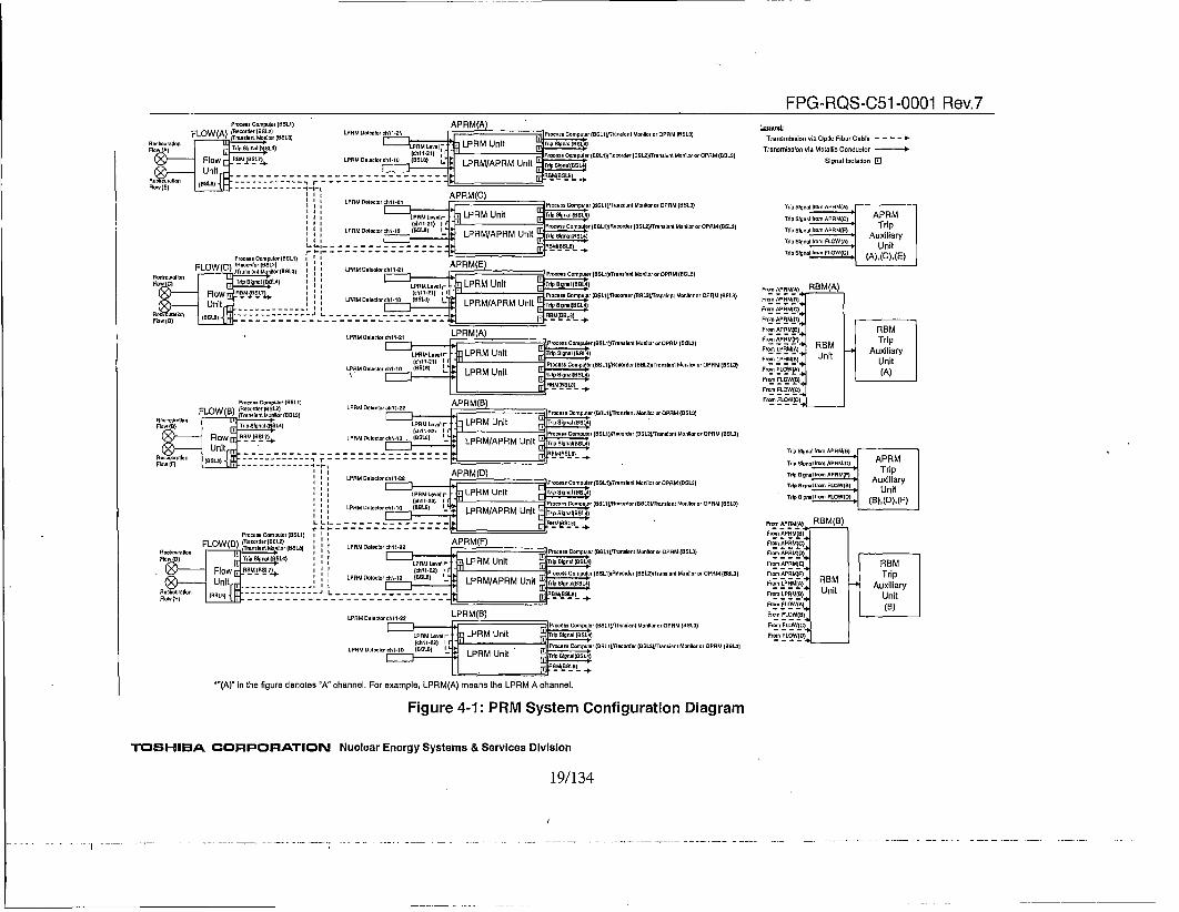
The PRM System configuration showing the subsystem interfaces is given in Figure 4-1.
TOSHIBA CORPORATION. Nuclear Energy Systems & Services Division
18/134
FPG-RQS-C51 -0001 Rev.7Pmo.sscompur (ADs) APRM(A)FLOW(A) .rr•t t
Mo~VD (BALD,) LFRM. Aeteol°roAhlOD' Poocooc Compoolon(BAL1,gre~nlonl MOAorOOPRB BOLD)
F• A),Top lon) )) ALO, LPRM Unit AA oI8 ,4(o , nittDBI) Pop.,e ODLpuLAC (BoL1)A Re dsr (BBLB)trorlonrle Mont[=ota OPAM (63L3)
IPOOor hiBDAPRM(C)PDODCmpoBBD(oieIBAAoFAOL(
I I (A)L ( LFFRM Unit ,TDpta(04(ch11-21) I 71lPj~op*g Carputr )BOLD))AoordoDOL)rproro2ero I Ont on~joroOPAL)(BALD)
'.I " LPAAOAB~or=r•0 (BALD) 1 LPRM/APRM Unit ' OBR BBLA
tB-I-.
FLOW(C) frro.ApLr(DBBLD APRM(E) Po.OA)(AD
I •l ;! '"° •" - LP RM/AR UnitFlow C) Trip omuOr BS1]Roorar(ns)( aOlLt D)l I O RM(IL3
LPRM (A)
J• LPRM Unit r.BeL•r~bZ•n~lLr oA OPrQPBA)AOL
Procce...p ConBrpol~coder(Br(BrBLDn) APFBrMPR IB)3
FLOW(B) o•. ~~j)(BuL( APA R M(B(LD
FeA B) Trip iRo)..BIB) LPRM UnRow JPt¢I•iIILPRM/APHMUnt P°• mpe BeRerr BL}rIn °toOPM(S)
' •' APRM(D)LPRM DatOPAMt (BOLD)
II I I ch112=)I ' [•P~asompter~SL1/Rerd~rBSL]mTemn) AOnllrororPRoM(BOLD)
014RI Deelrh-0 (•8 I LPRM P MUn t TrpSOPAL) (BALD
UntLRMARUnt
• LPR M(°h11"22) i . P~ee.Comlpoer (BBLDlIIR~osdnI Ap(~ BABGL•rnln (B~rrOLD) (BLLPPMMADADIF I -PRM Unit rl4 tm aIB$I(04)
*"A)" in tho figure danotes 0A" channel. For example, LPRM(A) meano the LPRM A channel.
Figure 4-1: PRM System Configuration Diagram
TOSHIBA CORPORATION Nuclear Energy Systems & Services Division
TransmisinvaOtcFbrCbe. .TrL)Osmiesson VIA O)M elADBllIo Conducto
TrIp Aignai From APAL))A)
TripnSoronamror APRSM)C")' - TrPRTrfpo81gnaoIfrm APRA)E) ATiiripTrip Signol Imor FLOW)A) UnitTAB~OIroP, FLA)C (A), (C),(E)
Frr APOL¶(A RBM(A)
Frrt APAL))BD)
Froml APAA)E)
For ,APRMF)FI0oIoLPRL)A) RBMFrrLPRL))B) UnitFr•n FLWA
Form FIOW(O(
Foom FLOW(C)
For FLBW(O)
REM
TripAuxiliary
Unit(A)
Trdo OorIs1ro APABM(B)•- APRM
AuxolliaryToOLInl, FO1• .owO() UnitTo,•,np~ PO.O)O) (B), (D),(F')
For APL)R)A) RBM(B)
Foor°'oAZPA-L{-)) REMIJ . [!
Fm..PRL).A)., REM - AuxiliaryFoooLPRAB).O-(.. Unit U itForoFO ()(B) I
19/134
FPG-RQS-C51 -0001 Rev.7
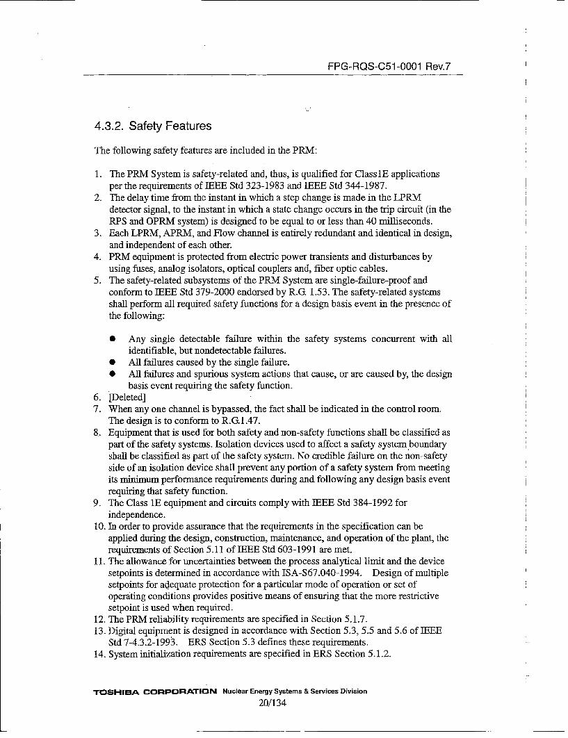
4.3.2. Safety Features
The following safety features are included in the PRM:
1. The PRM System is safety-related and, thus, is qualified for Class 1E applicationsper the requirements of IEEE Std 323-1983 and IEEE Std 344-1987.
2. The delay time from the instant in which a step change is made in the LPRMdetector signal, to the instant in which a state change occurs in the trip circuit (in theRPS and OPRM system) is designed to be equal to or less than 40 milliseconds.
3. Each LPRM, APRM, and Flow channel is entirely redundant and identical in design,and independent of each other.
4. PRM equipment is protected from electric power transients and disturbances byusing fuises, analog isolators, optical couplers and, fiber optic cables.
5. The safety-related subsystems of the PRM System are single-failure-proof andconform to IEEE Std 379-2000 endorsed by R.G. 1.53. The safety-related systemsshall perform all required safety functions for a design basis event in the presence ofthe following:
* Any single detectable failure within the safety systems concurrent with allidentifiable, but nondetectable failures.
* All failures caused by the single failure.* All failures and spurious system actions that cause, or are caused by, the design
basis event requiring the safety function.6. [Deleted]7. When any one channel is bypassed, the fact shall be indicated in the control room.
The design is to conform to R.G 1.47.8. Equipment that is used for both safety and non-safety functions shall be classified as
part of the safety systems. Isolation devices used to affect a safety system boundaryshall be classified as part of the safety system. No credible failure on the non-safetyside of an isolation device shall prevent any portion of a safety system from meetingits minimum performance requirements during and following any design basis eventrequiring that safety function.
9. The Class lE equipment and circuits comply with IEEE Std 384-1992 forindependence.
10. In order to provide assurance that the requirements in the specification can beapplied during the design, construction, maintenance, and operation of the plant, therequirements of Section 5.11 of IEEE Std 603-1991 are met.
11. The allowance for uncertainties between the process analytical limit and the devicesetpoints is determined in accordance with ISA-$67.040-1994. Design of multiplesetpoints for adlequate protection for a particular mode of operation or set ofoperating conditions provides positive means of ensuring that the more restrictivesetpoint is used when required.
12. The PRM reliability requirements are specified in Section 5.1.7.13. Digital equipment is designed in accordance with Section 5.3, 5.5 and 5.6 of IEEE
Std 7-4.3.2-1993. ERS Section 5.3 defines these requirements.14. System initialization requirements are specified in ERS Section 5.1.2.
TOSHIBA CORPORATION Nuclear Energy Systems & Services Division
20/134
FPG-RQS-C51 -0001 Rev.7
15. The points in time or the plant conditions for which the protective actions of thesafety system shall be initiated are specified in ERS Section 5.1.3.
16. The points in time or the plant conditions that allow returning a safety system tonormal are specified in ERS Section 5.1.4.
17. Auxiliary features (ex. Cooling fun, Power supply) comply with IEEE 603-1991.
4.3.3. System Availability
Loss of an APRM channel due to bypass or inoperability does not result in loss of thePRM System safety function, because the LPRM detectors are distributed throughoutthe core, at various distances from the core center, various azimuths, and variouselevations, and the LPRM detectors connected to each APRM channel are grouped sothat each APRM channel provides an average power level that is representative of thespatial average power throughout the core.
Loss of individual LPRM signals due to bypass or inoperability does not result in loss ofthe APRM safety function, because each APRM channel receives and averages 21 or 22LPRM signals. APRMs can function with loss of multiple LPRMs.
Any failure in the interconnection between units shall not defeat the ability of signaltransfer of information between the units.Loss of power in any units shall not defeat the ability of signal transfer between theunits.
4.3.4. Environmental Consideration
All safety-related PRM equipments have the ability to operate under the normal andaccident conditions specified in Section 5.5. These conditions must bound conditionunder the anticipated Operating Occurrences and the Design base accidents at the ratedpower operation.
All safety-related PRM equipments are qualified to minimize both susceptibility to, andgeneration of, electromagnetic interference (EMI) and radio frequency interference(RHI). The PRM Units are subjected to test for EMI, RFI, and surge conditions thatconform to guidelines given in RG-I .180 Revl1.
All safety-related PRM components are qualified to IEEE Std 323-1983 and IEEE Std344-1987.
4.3.5. Maintenance Provisions
The PRM equipment design provides the replacement capability of all modules. All
modules performance is readily measurable.
TOSHIBA CORPORATION Nuclear Energy Systems & Services Division
21/134

FPG-RQS-C51 -0001 Rev.7
4.3.6. Self-Testing
The self-test functions are described in the Section 5.1.6.
4.3.7. Surveillance Testing
The PRM System provides the following functions for surveillance testing:
a. LPRM gain adjustment. (See 4.4.3.)b. APRM gain adjustment. (See 4.4.3.)c. LPRM trip test.d. APRM trip test.e. Flow trip test.
4.4. Operation4.4.1. Operation
The PRM System operates continuously during reactor operation. The accuracy of theAPRM channels can be verified by cross-comparison of the each other redundantchannels within the two redundant divisions. The bypass of one channel of three APRMchannels for one RPS division is allowable, because of the one out of two taken twicetype RPS trip logic. The PRM System fully meets the requirements stated in R. G. 1.22.
4.4.2. Operating Bypasses
The PRM System uses an operational bypass that changes the reactor trip setpoint androd withdrawal setpoint depending on two inputs: reactor mode and recirculation flowrate. Specifically, the operational bypass functions as follows:
* When the reactor operating mode switch is in the "RUN", the APRM reactor tripand the rod withdrawal block setpoints are dependent upon the recirculation flowrate.
* When the reactor operating mode switch is NOT in the "RUN", the APRM is stillcapable of issuing trips and the rod withdrawal block signals, but at a lower fixedsetpoint.
4.4.3. Calibration
(1) LPRM gain adjustmentLPRM calibration is performed for each APRM channel and LPRM channel. Theoperator bypasses the APRM channel to be calibrated (this process is not executed forLPRM channel). The operator places the LPRM mode switch in the "CAL" position andenters a new gain adjustment value. After entering new gain adjustment value, theoperator places the LPRM mode switch in the "OP" position. The operator then
TOSHIBA CORPORATION Nuclear Energy Systems & Services Division
22/134
FPG-RQS-C51 -0001 Rev.7
removes the bypass of the channel. This process is repeated for each LPRM (except forchannel bypass process for LPRM channel), or APRM channel.
(2) APRM gain adjustmentAPRM calibration is performed for each APRM channel (this process is not executedfor LPRM channel). The operator bypasses the APRM channel to be calibrated andplaces the APRM mode switch in the "CAL" position and enters new gain adjustmentvalue. After entering new gain adjustment value, the operator places the APRM modeswitch in the "OP" position and remove the bypass.An analysis shall be prepared to provide the information needed to support anapplication specific setpoint analysis per ISA-RP 67.04. The analysis shall include:
a. Calibrated accuracy, including hysteresis and non-linearity, of the analoginputs.
b. Repeatability of the analog inputs.c. Temperature sensitivity of the analog inputs.d. Drift with time of the analog inputs.e. Power supply voltage fluctuation effects on the analog inputs.
In addition, the qualification process shall identify components, if any, on analog inputmodules as follow:
a. Components where vibration during seismic testing could affect accuracy.b. Components where radiation exposure could affect accuracy.c. Component where relative humidity over the range given in Section 5.5
could affect accuracy.
(3) Flow CalibrationFlow calibration is performed for each Flow channel. The operator bypasses the Flowchannel to be calibrated and adjust the output signal to test current input signal.
4.4.4. Unit and Detector Bypass
Each LPRM, APRM or Flow channel can be individually bypassed for maintenancebypass. Restrictions as to the total number and distribution of bypassed channels (at onetime) must be adhered rigidly to avoid reactor trip due to inoperable PRM channels.
The APRM equipment allows the operator to bypass any one of the 3 APRM channelsfor one RPS division during normal plant operation. The APRM channel bypassedstatus is displayed on the PRM front panel and provided to the MOC complying withR.G 1.47.
All PRM bypass logic control functions are located within the PRM, none are located inRPS.
Each LPRM modules allows to be bypassed within the permissive numbers to retain thePRM Safety function. The LPRM module (including LPRM detector) bypass status is
TOSHIBA CORPORATION Nuclear Energy Systems & Services Division
23/134
FPG-RQS-C51 -0001 Rev.7
displayed on PRM front panel.
4.5. System Interface
The PRM System has interfaces to other systems, described in the following. Of these
interfaces, Table 4.2 summarizes the PRM System discrete outputs.
4.5.1. Reactor Manual Control System (RMCS)
The PRM System provides discrete signals to RMCS as follows:
The discrete signals from the PRM to the RMCS through the trip auxiliary unit:
APRM Inoperable OR of all APRM channelsAPRM Upscale (High) OR of all APRM channelsAPRM Downscale OR of all APRM channelsRecirculation Flow Upscale OR of all FLOW channelsRecirculation Flow Inoperable OR of all FLOW channels
These discrete output signals are used as the rod withdrawal block signals.
4.5.2. Reactor Protection System (RPS)
Each APRM channel provides the trip signal to the RPS as described in Section 4.3.1.
The RPS provides the PRM System with the position and control information of thereactor mode switch, e.g. RPS provides the signal indicating if the mode switch is in the"RUN" position.
Discrete signals from the RPS to the PRM:
Reactor Mode signalAPRM Bypass signal
Discrete signals from the PRM to the RPS through the trip auxiliary unit:
APRM Upscale (High-High) Each APRM channelSimulated Thermal Power Upscale Each APRM channelAPRM Inoperable Each APRM channel
These signals are used to initiate the reactor scram.
4.5.3. Process Computer System (PCS)
PRM provides data signals, trip indications and operation status to the PCS.
TOSHIBA CORPORATION Nuclear Energy Systems & Services Division
24/134

FPG-RQS-C51 -0001 Rev.7
Analog signals from the PRM to the PCS:
LPRM levelsAPRM levelsAPRM Upscale (High) setpointsSimulated Thermal Power LevelsSimulated Thermal Power Upscale setpointsLoop Flow valuesDifferential Pressure valuesRecirculation Flow values
0Oto 160mY signal for 0to 125%0 to 160mV signal for 0 to 125%0 to l60mV signal for 0 to 125%0Oto 160mV signal for 0to 125%0 to 160mV signal for 0 to 125%0 to l60mV signal for 0 to 125 %32 to 160 mV signal for 4 to 20rmA0Oto l60mV signal for 0to125 %
Discrete signals from the PRM to the PCS through the trip auxiliary unit:
APRM Upscale (High-H~igh)Simulated Thermal Power UpscaleAPRM Upscale (High)APRM InoperableAPRM DownscaleAPRM BypassRecirculation Flow UpscaleRecirculation Flow Inoperable
Each APRM channelEach APRM channelEach APRM channelEach APRM channelOR of all APRM channelsEach APRM channelOR of all Flow channelsOR of all Flow channels
4.5.4. Oscillation Power Range Monitor (OPRM)
The PRM System can provide the analog signals of the LPRM levels to the OPRMsystem. The analog signals are identical to the signals that are provided to the transientmonitor.
If an LPRM module is bypassed or becomes inoperable, it continues sending the lastLPRM level to the OPRM, so the OPRM may identify the inoperable LPRM bydetecting the constancy of the LPRM levels.
I 4.5.5. Main Operator Console (MOO)
]Discrete signals from the PRM System to the MOC through the trip auxiliary unit:
LPRM Unit Minor failureLPRM/APRM Unit Minor failureAPRM Upscale (High-High)APRM InoperableAPRM Upscale (High)Simulated Thermal Power UpscaleAPRMv DownscaleAPRM Minor FailureAPRM BypassRecirculation Flow UpscaleRecirculation Flow Inoperable
Each LPRM UnitEach LPRM/APRM UnitEach APRM channelEach APRM channelEach APRM channelEach APRM channelEach APRM channelEach APRM channelEach APRM channelEach FLOW channelEach FLOW channel
TOSHIBA, CORPORATION Nuclear Energy Systems & Services Division25/134
FPG-RQS-C51 -0001 Rev.7
4.5.6. Annunciator (ANN)
Discrete output from the PRM System to the ANN through the trip auxiliary unit:
LPRM UpscaleLPRM DownscaleAPRM Upscale (High-High)Simulated Thermal Power UpscaleAPRM InoperableAPRM Upscale (High)APRM DowuscaleAPRM Minor Failure
Recirculation Flow UpscaleRecirculation Flow Inoperable
OR of all LPRM modules*OR of all LPRM modules*Each RPS trip systemEach RPS trip systemEach RPS trip systemOR of all APRM channelsOR of all AIPRM channelsOR of all LPRM Unit MinorFailure, APRM Minor Failure andFLOW Unit Minor FailureOR of all Flow channelsOR of all Flow channels
*See. Section 5.2.3.2 about LPRM module
4.5.7. Recorder
Analog output from PRM System to the Recorder:
APRM levelsAPRM Upscale (High) setpointsRecirculation Flow values
0 to 1V signal for 0 to full scale0Oto 1V signal for 0to 125%0Oto lV signal for 0to125%
TOSHIBA CORPORATION Nuclear Energy Systems & Services Division26/134

FPG-RQS-C51 -0001 Rev.7
Table4-2. Discrete Output from the PRM System
Destination of OutputType of Output IRMCS IRPSLPRM Upscale -- --
LPRM Downscale -- --
LPRM Unit Minor Failure
LPRM/APRM Unit Minor Failure -- --
APRM Upscale (High-High) -- 0Simulated Thermal Power Upscale -- 0
APRM Inoperable © 0APRM Upscale (High) © --
APRM Downscale © --
•APRM Minor Failure -- --
APRM Bypass -- --
Recirculation Flow Upscale © --
Reciculation Flow Inoperable _ --
FLOW Unit Minor Failure -}--] --
O:each channel *:each RPS trip system ©:or of all channels A~AhunitX: or of all LPRM modules (See Section 5.2.3.2 about LPRM module)* OR of all LPRM Unit Minor Failure, all LPRM/APRM Unit Minor Failure, all APRM
Minor Failure and FLOW Unit Minor Failure
TOSHIBA CORPORATION Nuclear Energy Systems & Services Division27/134

FPG-RQS-C51 -0001 Rev.7
5. Design RequirementsThis section specifies the detailed functional requirements for the hardware andsoftware components of the system (Section 5.1), the hardware requirements for eachhardware component (Section 5.2), and generic software requirements for all logic(Section 5.3).
5.1. Functional Requirements5.1.1. Basic Design Requirements
The PRM System shall be designed to provide adequate flux monitoring informationfr~om one percent through 125% reactor power. In order to allow this PRM systemmeasurement, the LPRM indication shall be adjusted not to exceed 86% at the ratedpower. Note that the PRM System can accept 13 8.9% flux value at maximum, and if theflux value exceeds the limit, it is clamped to the 138.9%.
The PRM System shall provide trip functions for required safety protection. It shall alsoprovide continuous and reliable reactor power performance data to the various outputinterfaces.
]The PRM System shall be able to compare the signal input to the setpoints, and generatealarms or trip signals.
The PRM System shall be capable of latching alarm conditions and resetting based onalarm reset conditions. The display for the PRM units (e.g., LPRM Display) shallprovide a manual reset button to perform this action.
The PRM System shall be capable of monitoring its operability and show it external tothe PRM System (i.e., using a discrete output to activate a LED), so that the operatorcan visually confirm the PRM System is currently operating.
These functions specified in this section shall be performed by logic in the equipment.
5.1.2. System Initialization Requirements
Whenever power is applied to the PRM equipment, the equipment shall be initialized bypower on reset function.
All trip and alarm outputs shall remain tripped until the initialization process hascompleted (about 470ms). After initialization, the trip and alarm outputs shall assumethe states indicated by calculations and bypass settings.
Power on reset function shall also be executed when the power supply low voltage isdetected.
L
TOSHIBA CORPORATION Nuclear Energy Systems & Services Division
28/134 !

FPG-RQS-C51 -0001 Rev.7
The module is provided with the power supply monitoring IC, and it executes about150ms reset action and initial startup of FPGA at the time when the module is energized.In addition, it executes a reset action also at the time when the power supply voltagelowers, i.e. if the power supply low voltage continues to be low, the module shallremain in initialization state, and keep all trip and alarm outputs tripped.
The PRM System shall be capable of performing run time diagnostics.
5.1.3. Nominal System Setpoints
The PRM trip setpoints shall be adjustable by a technician during equipmentmaintenance or an operator during periodical surveillance service. The PRM Systemshall support setpoint adjustments of equipment on the front panel. Adjustments shallinclude increase and decrease of the setpoint.
Table 5-1 and Table 5-2 show the recommended LPRM and APRM trip setpointsrespectively.
LPRM gain shall be adjusted 400p.A/100% or 2400k.A/100% as long as there is nospecial requirements in testing, and shipping.
TOSHIBA CORPORATION Nuclear Energy Systems & Services Division
29/134

FPG-RQS-C51 -0001 Rev.7
Table 5-1. Recommended LPRM trip setpoints
I REACTOR [CTIO SEP INT TIAGTRIP FUNCTION MODE ATO EPIT TI AG
LPRM Upscale -- Lgtandn{000ciatto12r/
LpMonc~-Light and 5 %t 0PR Donce -- annunciator 5/ 0 ot 0
TOSHIBA CORPORATION Nuclear Energy Systems & Services Division30/1 34
FPG-RQS-C51 -0001 Rev.7
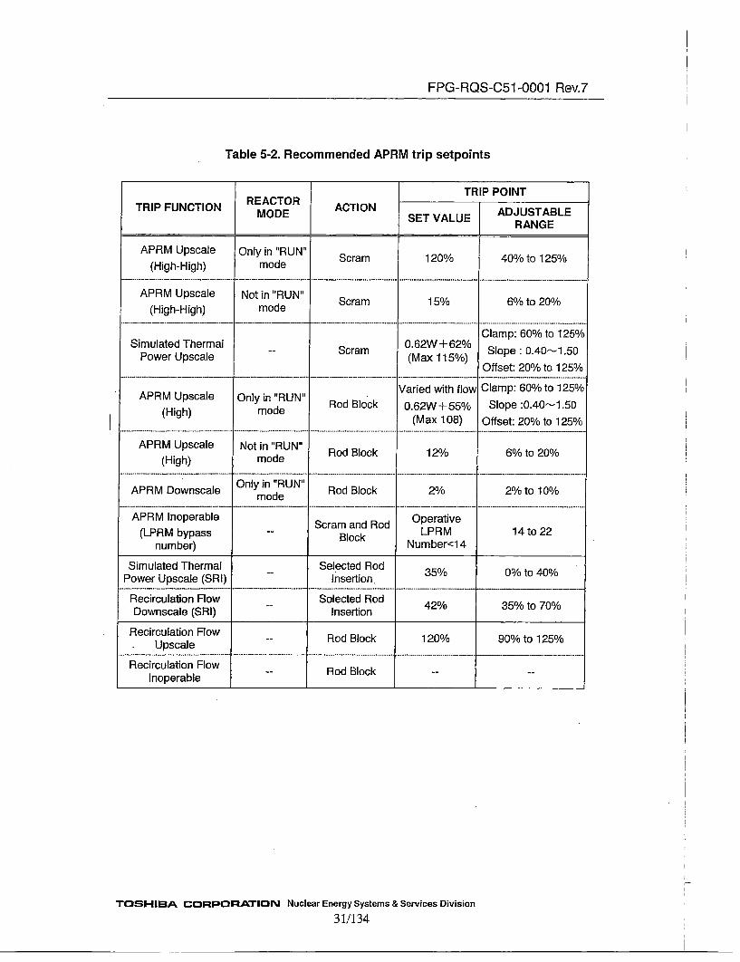
Table 5-2. Recommended APRM trip setpoints
TRIP POINTTRIP FUNCTION RECORE ACTION IADJUSTABLE
MODE ~SET VALUE RAG
APRM Upscale Only in "RUN" Sca12%4/to25o(High-High) mode
APRM Upscale Not in "RUN" Sca15/6%t20(High-High) mode
Clamp: 60% to 125%Simulated Thermal Srm 0.62W +62% Slp:.4--.5
Power Upscale -- (Max 115%)Offset: 20% to 125%
Varied with flow Clamp: 60% to 125%APRM Upscale Only in "RUN"' o lc .2+5% Soe:.015
(High) mode RoBlc o62ss Slp 04--15(Max 108) Offset: 20% to 125%/
APRM Upscale Not in "RUN" o lc 2 %t 0/(High) mode
APRM Downscale Only in "RUN" Rod Block 2% 2%/ to 10%
mode
APRM Inoperable Scram and Rod Operative(LPRM bypass -- Block LPRM 14 to 22
number) Number<14
Simulated Thermal Selected Rod 3%0 o4VPower Upscale (SRI) Insertion 3%0 t 0
Recirculation Flow Selected Rod 4003%t 0Downscale (SRI) Insertion
ecruainFo -Rod Block 120% 90% to 125%Upscale
Recirculation Flow - o lc --
Inoperable
TOSHIBA CORPORATION Nuclear Energy Systems & Services Division31/134

FPG-RQS-CSI -0001 Rev.7
5.1.3.1. Response Time Requirements
For the APRM trip signals, Rod withdrawal Block signals, and LPRM signals, theresponse times shall be measured as the delay time from an input signal change to thecorresponding output signal change.
~The PRM System shall be capable of transferring data between units'.The actual response time of each module in the PRM System shall be determined duringqualification testing.
I1. APRM Trip signal(1) APRM Upscale (High-High)The response time, which is measured as the total delay time from a step change ofthe LPRM input current to the change of the APRM trip auxiliary unit output, shallbe equal to or less than 40 milliseconds.
The step change shall be made in the following condition:
LPRM input: [ ]•o--). ] step changeLPRM gain" [ J/10APRM gain: [ Pd~though monitoring range of the APRM level
is 0 to 125%, the APRM module can acceptsignals up to 138.9%)
APRM Upscale (High-High) set value: 120%
An expected response time for modules and units shall be as follows:
Item TimeLPRM module [ ]•ts'z or lessTransmission between units -i [ Jhs.2 or lessAPRM module [ Yids~z or lessDIO module rI )]is"1 or less(APRM trip auxiliary unit) [ ]•f1s. or lessTotal 40 ms*2 or less
*1: Transmission from LPRM unit to the LPRM/APRM unit*2 "Minliseconds
(2) Simulated Thermal Power UpscaleSimulated Thermal Power Level is calculated from APRM output withi 6 secondstime constant delay.The response time shall be measured by either of the following methods:
a) Method 1The response time shall be measured as the total delay time from when a stepchange is made in the LPRM input current until the APRM trip auxiliary unit
TOSHIBA CORPORATION Nuclear Energy Systems & Services Division
32/134

FPG-RQS-C51 -0001 Rev.7
outputs the Simulated Thermal Power Upscale trip. The response time shall beequal to or less than[ ]•llseconds ([ )li'lliseconds* + 40miliseconds**) atthe following condition.
* Time that Simulated Thermal Power, which has [ fseconds time constant
delay reach TPM Upscale set value at the following condition.**Time from simulated thermal power reaches TPM Upscale set value to the
-change of state of the trip circuit (to RPS).
LPRM input:Time constant:LPRM gain:APRM gain:
TPM Upscale set value:
[ ]•--) ]• step change[ J conds[ ] /100%[ ]•Altho'ugh monitoring range of the APRM level
is 0 to 125%, the APRM module can acceptsignals up to 138.9%)115%
An expected response time for modules and units shall be as follows:Item Tune
LPRM module [ •. or lessTransmission between units *l ]nhs"2 or lessAPRM module [ ns.2 or lessDIO module [ •- or less(APRM trip auxiliary unit) [I ]ris. or lessTotal 40 ms. 2 or less
* 1: Transmission from the LPRM unit to the U'RM/APRM unit*2 :Milliseconds
b) Method 2The response time shall be measured by following 2 steps:
•SteplThe interval time is measured from when a step change is made in the LPRMinput current until the APRM trip auxiliary unit outputs the APRM Upscale(High-High) trip. The interval time shall be equal to or less than 40milliseconds at the following condition:
LPRM input:Time constant:LPRM gain:APRM gain:TPM Upscale set value
[ Ig--[ ]•.step changeFI )•'&ond
[ ]~
115%
ac]~A/l00%
* Step2The interval time is measured from when the Simulated Thermal Power Level
TOSHIBA CORPORATION Nuclear Energy Systems & Services Division33/134
FPG-RQS-C51 -0001 Rev.7
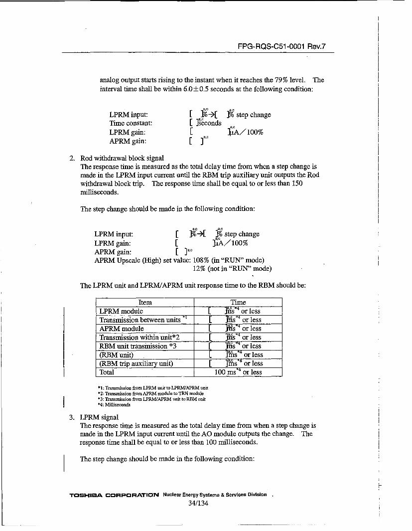
analog output starts rising to the instant when it reaches the 79 % level. Theinterval time shall be within 6.0_±+0.5 seconds at the following condition:
LPRM input:Time constant:LPRM gain:APRM gain:
[ i•--)[ ]% step change[ ]•'conds[ ]p.A/100%
ac°'
2. Rod withdrawal block signalThe response time is measured as the total delay time from when a step change ismade in the LPRM input current until the RBM trip auxiliary unit outputs the Rodwithdrawal block trip. The response time shall be equal to or less than 150milliseconds.
The step change should be made in the following condition:
LPRM input: [ ]%'-)[ ]7 step changeLPRM gain: [I ]LiA/100%APRM gain: [ ]a'cAPRM Upscale (High) set value: 108% (in "RUN" mode)
12% (not in "RUN" mode)
The LPRM unit and LPRM/APRM unit response time to the RBM should be:
Item TimeLPRM module [ J•ais. 4 or lessTransmission between units *• [ •iis•4 or lessAPRM module [1 jItes. or lessTransmission within unit*2 [ fts.4 or lessRBM unit transmission *3 -[ }nas.4 or less(RBM unit) [ ]i•as. 4 or less(RBM trip auxiliary unit) [ ]•as. 4 or lessTotal 100 msa4 or less
*1: Transmission from LPRM unit to LPRM/APRM unit*2: Transmission from APRM module to TRN module*3: Transmission from LPRM/APRM unit to RBM unit*4: Milliseconds
3. LPRM signalThe response time is measured as the total delay time from when a step change ismade in the LPRM input current until the AO module outputs the change. Theresponse time shall be equal to or less than 100 milliseconds.
The step change should be made in the following condition:
TOSHIBA CORPORATION Nuclear Energy Systems & Services Division
34/ 134
H

FPG-RQS-051 -0001 Rev.7
LPRM input: [ 1%- 1% step changeLPRM Gain: [I ]4A11 1%
[ LPRM analog output signal of the LPRM unit and the LPRM/APRM unit responsetime to LPRM analog output signal of Transient Monitor system should be:
Item TimeLPRM module [I ]Ytfs or lessAO module [ ]•As or lessTotal 2lnis or less
5.1.4. Drift and Accuracy Requirements
1. LPRM functiona. The LPRM drift over a period of two weeks shall not exceed ±-1.0 % full scale
(FS) at control room environmental conditions.b. The LPRM input-and-output linearity (inaccuracy) shall be within ±2.0% FS,
at control room environmental conditions.Note: 1. PS is from 0% to 125% reactor power.
2. The LPRM drift and linearity are measured from the LPRM input currentto the LPRM output through the AO module.
2. APRM functiona. The APRM drift over a period of two weeks shall not exceed +1.0 %FS at
control room conditions.b. The APRM input-and-output linearity (inaccuracy) shall be within ±-2.0% FS.c. The APRM function shall be so designed that, at control room environmental
conditions, trip accuracy shall be as follows:Scram signal:
Within ±-2.0% FSRod withdrawal signals:
Within ±-3.0% PS (FLOW: 0 to 50%)Within ±-2.0% FS (FLOW: 50 to 125%)
d. The trip reset point shall be- -. 25% FS below trip set point.
Note: 1. FS is from 0% to 125% reactor power.2. The APRM drift, linearity and trip accuracy are measured from the LPRMinput current to the APRM output through the AO module.
3. FLOW functiona. The FLOW function shall be so designed that, at control room environmental
conditions, the drift over a period of two weeks shall not exceed ±1.0 %FS.b. The FLOW function shall be so designed that the input-and-output linearity
(inaccuracy) and the trip accuracy at control room environmental conditions isas follows.
Within ±-3.0% FS (FLOW: 0 to 50%)Within ±-2.0% FS (FLOW: 50Oto 125%)
TOSHIBA CORPORATION Nuclear Energy Systems & Services Division3 5/134
FPG-RQS-C51 -0001 Rev.7
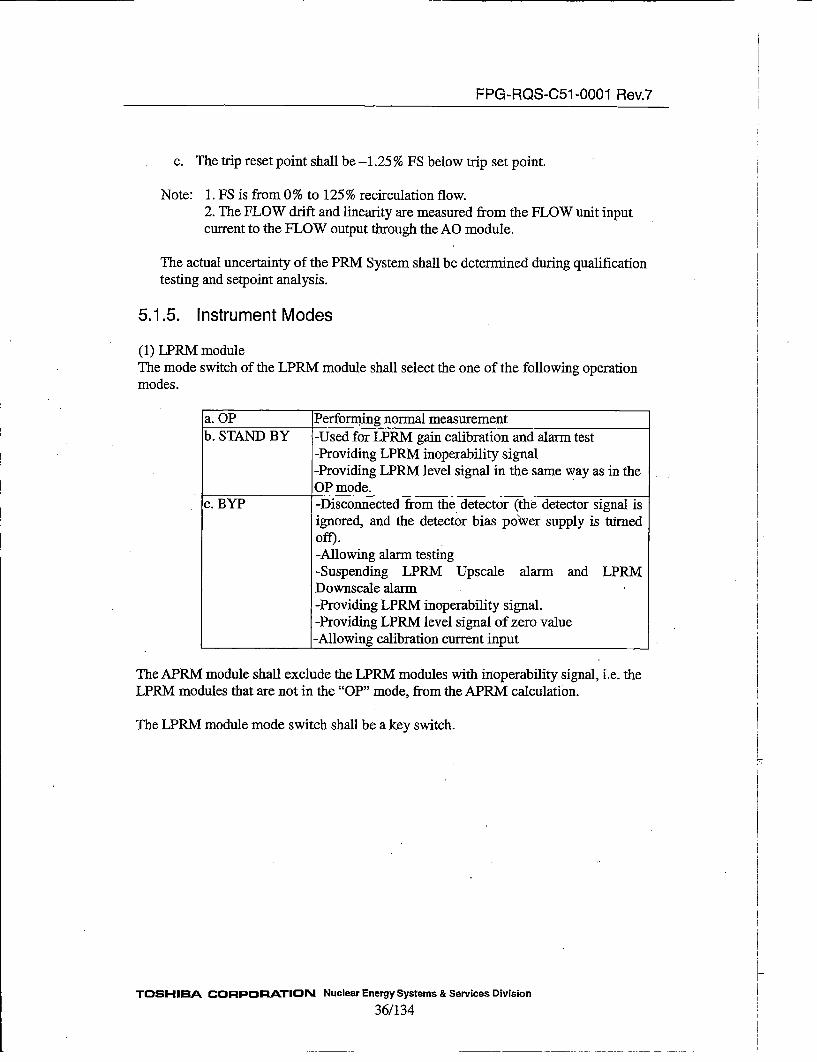
c. The trip reset point shall be -1.25% FS below trip set point.
Note: 1. FS is from 0% to 125% recirculation flow.2. The FLOW drift and linearity are measured from the FLOW unit inputcurrent to the FLOW output through the AO module.
The actual uncertainty of the PRM System shall be determined during qualificationtesting and setpoint analysis.
5.1.5. Instrument Modes
(1) LPRM moduleThe mode switch of the LPRM module shall select the one of the following operationmodes.
a. OP Performing normal measurementb. STAND BY -Used for LPRM gain calibration and alarm test
-Providing LPRM inoperability signal-Providing LPRM level signal in the same way as in theOP mode.
c. BYP -Disconnected from the detector (the detector signal isignored, and the detector bias po~wer supply is turedoff).-Allowing alarm testing-Suspending LPRM Upscale alarm and LPRMDownscale alarm-Providing LPRM inoperability signal.-Providing LPRM level signal of zero value
___________-Allowing calibration current input
The APRM module shall exclude the LPRM modules with inoperability signal, i.e. theLPRM modules that are not in the "OP" mode, from the APRM calculation.
The LPRM module mode switch shall be a key switch.
TOSHIBA CORPORATION Nuclear Energy Systems & Services Division
36/134

FPG-RQS-C51 -0001 Rev.7
(2) APRM moduleThe mode switch of the APRM module shall select the one of the following operationmodes.
a. OP Performing normal data processing
b. STANDBY Providing APRM inoperability signalData processing continues in the same way as in theOP mode.
c. CAL -Allowing APRM gain calibration-Allowing trip testing-Providing APRM inoperability signal
Data processing continues in the same way as in theOP mode using the injected calibration signal.
APRM inoperable signal shall be provided at the times other than "OP" mode.
The APRM module mode switch shall be a key switch.
(3) FLOW moduleThe mode switch of the FLOW module shall select the one of the following operationmodes.
a. OP Performing normal measurement
b. CALl FLOW -Allowing trip testing with the total recirculation-flow-ratevalues entered from the FLOW unit front panel-Providing inoperability signal to the LPRM/APRM unit andother external equipment-Providing the entered Flow value to the LPRM!APRM unitand other external equipment.
c. CAL2 LOOP -Allowing checking of the total-flow-rate values entered fromthe variable resister of the front panel of the SQ-ROOTmodule-Providing inoperability signal to the LPRM/APRM unit andother external equipment-Providing the entered Flow value to the LPRM/APRM unitand other external equipment.
The FLOW module inoperable signal shall be provided at the times other than 'COP,,
mode.
The FLOW module mode switch shall be a key switch.
TOSHIBA CORPORATION Nuclear Energy Systems & Services Division
3 7/134

FPG-RQS-C51 -0001 Rev.7
5.1.6. Failure Detection and Self Test RequirementsThe FPGA equipment shall have diagnostic functions as follows:
(a) Monitoring of the Low Voltage Power Supply moduleThe Low Voltage Power Supply (LVPS) module shall monitor its output voltage.If the voltage of the LVPS becomes lower than the setpoint[ 1]6[ •c in either of
the LVPS module, the STATUS module front panel shall provide the indication.
(b) Moni'toring Low Voltage Supply for each moduleThe LPRM, APRM, SQ-ROOT, FLOW, TRN, RCV, and STATUS modules shallmonitor the input voltage from the LVPS modiules. If the input voltage becomeslower than the setpoint, the module shall be reset.
(c) Monitoring of the FPGAs with a WatchdogA watchdog timer shall monitor each FPGA that operates periodically. A group ofFPGAs that operates serially may be monitored by[ ]watchdlog timer, as long asthe •tchdog timer can detect the[ ].•c if a[ ]'[ 1,'the module containing the FPGA shall generate an inoperable signal. Thefailure of theE ) s~hall not generate aninoperable signal, but a Minor Failure Alarm, except for the LPRM module. Thewatchdog timers shall be external, and not built into the FPGA logic, nor shall thewatchdog timer depend on the clock signal used by the FPGA.
(d) [Delete]
(e) Checking data transmission between units via fiber optic cablesThe module receiving data from the other unit shall verify the periodic occurrenceof the data transmissions, and the validity of transmitted data between units overfiber optic cables. The validity of data shall be verified by parity checks for each
[I •]t word in the transmitted data frame.
(f) Checking data transmission from the modules in a same unitThe APRM module shall check the periodic transmission of the data frame fromthe TRN modules and the RCV modules in the same unit. If a[]'occurs, a Minor Failure signal shall be generated.
(g) Checking constants stored in Rewritable ROMEvery Rewritable ROM storing constants used for the signal processing shallprotect its value with parity bits or dual storage. If an error is detected, a MinorFailure alarm shall be generated.
(h) Checking the voltage of the LPRM High Voltage Power SupplyThe LPRM module shall monitor the voltage of the High Voltage Power Supply.If the voltage becomes lower than the setpoint, the LPRM shall be inoperable.Inoperable of single LPRM module does not affect the Safety-Related function.
TrOSHI1A CORPORATION Nuclear Energy3813Systems & Services Division

FPG-RQS-051 -0001 Rev.7
(i) Checking the input value of the SQ-ROOT moduleThe SQ-ROOT module shall perform range check for the input current value afterdigital conversion. If the input current value meets either of the followingconditions, the SQ-ROOT module shal~Jcoutput failure si!nal:a
Input Current Value < Setpoint[ ]7 FS (FLOW: [ Jto [ ]•)Input Current Value < Setpoint[ ]%• FS (FLOW:[ ]•' [ I
Note: 1. FS is from 0% to 125% recirculation flow.2. The FLOW drift and linearity are measured from the FLOW unit input currentto the FLOW unit output through the AO module.
5.1.7. AvailabilitylReliability Requirements
1. The overall availability of the PRM units shall be 0.99. An availability calculationshall be prepared in the manner that conforms to IEEE 352-1987. The availabilityanalysis shall include random hardware failure rates only for the units andcomponents that constitute the PRM System.
2. The availability of the units shall be calculated for the combination of units to bepart of one channel, e.g., 1 LPRM/APRM unit, 2 FLOW units, cables, and thepower supplies.
3. Each unit shall have an availability goal of 0.99 on the condition that Mean Time ToRepair (MlTrR) is 24 hours.
The availability analysis shall include a calculation of the surveillance intervalrequired to support the availability goal for those failures that are only detectable byperiodic surveillance testing. In addition, the availability resulting from 6 monthssurveillance intervals shall be calculated.
4. The mean time between failure (MTBF) of each subcomponent shall be calculatedusing the reference given in MIL-I-DBK 217FE
5. A Failure Modes and Effects Analysis (FMEA) shall be performed in accordancewith IEEE Std 352-1987. For each component that constitutes the modules, theanalysis shall evaluate its failure modes and effects on the PRM unit performance.The FMEA shall also identify the following items:
a. Those faults that will be detected by the rmn-time diagnostics.
b. Faults that can only be detected by surveillance testing.c. For redundant components, e.g., LVPS modules
i) States that result from one or more failures where the system remainsoperable as well as where it is not operable.
i~i) States where undetected failures have occurred.
TOSHIBA CO)RPOR=ATION Nuclear Energy Systems & Services Division39/134
FPG-RQS-C51 -0001 Rev.7
iii) States where a failure in a single component has caused the PRM System tofail.
iv) State where failures reduce the effectiveness of self-diagnostics.
5.1.8. Test Circuit Requirements
Any built-in test circuits in a modules or FPGA shall not have adverse effects on thesafety functions of the PRM system.
5.2. Hardware Requirements5.2.1. Unit Configuration Requirements5.2.1.1. Assignment of Units for Subsystem
Each APRM channel contains one LPRM unit and one LPRM/APRM unit. Each LPRMChannel contains two LPRM units. Each Recirculation Flow Measurement channelcontains one FLOW unit. Therefore, the equipment specified in this .documentconsists of ten LPRM units, six LPRM/APRM units, and four FLOW units.
1. The LPRM/APRM unit has functions of the APRM subsystem, which are receivingtwo recirculation flow signals from the two FLOW units, averaging all the LPRMdetector signals in the division to provide the APRM level and the SimulatedThermal Power Level, and Providing appropriate readout and alarms for operatoraction or attention.
2. The LPRM unit and the LPRM/APRM unit have functions of the LPRM subsystem,which are providing local power level information of the reactor core and providingappropriate readout and alarms for operator action or attention.
3. Each LPRM detector shall be assigned to one LPRM module in an LPRM unit or anLPRMIAPRM unit.
4. The FLOW unit shall provide total recirculation flow information and provideappropriate readout and alarms .for operator action or attention.
The FLOW unit assignments are described in Section 4.3.
5.2.1.2. Unit Hardware Hierarchy
Modules are placed inside chassis, to form units. Each module contains one or morePrinted Circuit (PC) boards, which mounts FPGAs containing embedded logic. Thelogic of the FPGAs is performed by the functional elements, which are discreteprogramming elements containing simple logic.
TOSHIBA CORPORATION Nuclear Energy Systems & Services Division
40/134
FPG-RQS-C51 -0001 Rev.7
5.2.1.3. LPRM Unit and Module Configuration
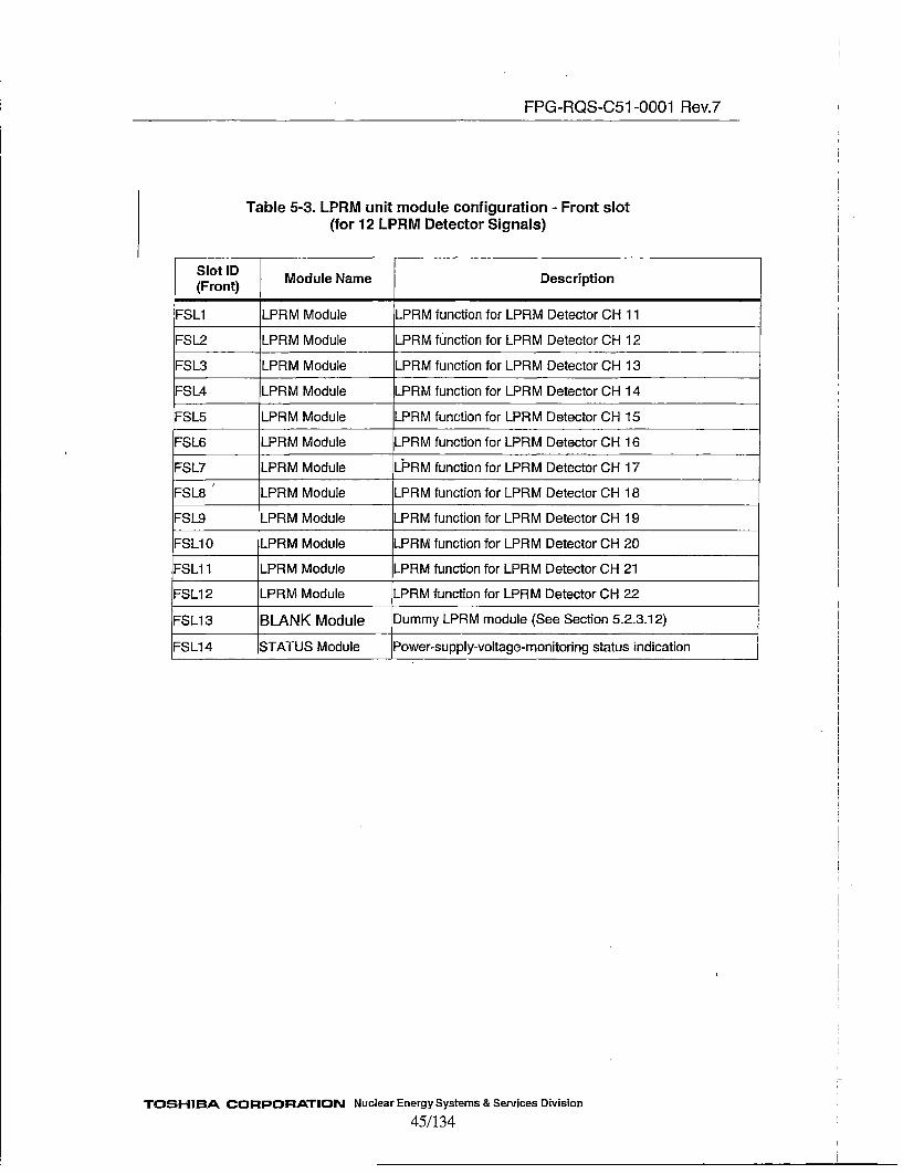
Table 5-3 and 5-4 show module configuration of the LPRM unit.
5.2.1.4. LPRMIAPRM Unit Module Configuration
Table 5-5 and 5-6 show module configuration of the LPRM/APRM unit.
5.2.1.5. FLOW Unit and Module Configuration
Table 5-7 and 5-8 show module configuration of the FLOW unit.
5.2.2. Unit Input/Output Requirements
The PRM System consists of the LPRM units, the LPRM/APRM units, and the FLOWunits. The input and output requirements for these units are described in the following.
5.2.2.1. LPRM Unit
The LPRM unit shall have following Analog inputs, Analog outputs, and Discreteoutputs:
Analog input:* From LPRM detector
11 LPRM signals12 LPRM signals
for division A:for division B:
Analog output:(a) To LPRM/APRM Unit digital optical data transmission
11 LPRM signals for APRM channels A, C, E:12 LPRM signals for APRM channels B, D, F:LPRM Inoperable information
(b) To Process ComputerLPRM level
(c) To Transient MonitorLPRM level
Discrete Output:•To trip auxiliary unit
LPRM UpscaleLPRM DownscaleLPRM Inoperable
o to 160mV signal for 0 to 125%
1 toS5Vsignal for 0to 125%
OR of 11 or 12 LPRM detector channelsOR of 11 or 12 LPRM detector channelsOR of 11 or 12 LPRM detector channels
TOSHIBA CORPORATION Nuclear Energy Systems & Services Division41/134

FPG-RQS-C51 -0001 Rev.7
5.2.2.2. LPRMIAPRM Unit
Analog input:
(a) From LPRM unit digital optical data reception11 LPRM signals for APRM channels A, C, E:12 LPRM signals for APRM channels B, D, F:LPRM Inoperable information
(b) From LPRM detector10 LPRM signals
(c) From FLOW unit digital optical data receptionIndividual Recirculation Flow values
Discrete input:
•From Trip Auxiliary unitThe Reactor Mode signalThe APRM bypass signal
Notice: APRM channels shall be designed to allow bypass one of threeAPRM channels that send the trip signals to one RPS division.
2 Flow bypass signalsAnalog output:
(a) To Rod Block MonitorLPRM levelAPRM level
digital optical data transmission
Simulated Thermal Power Level
(b) To Process Computer 0 to 1 60mV signal for 0 to 125%LPRM levelAPRM levelSimulated Thermal Power LevelAPRM Upscale (High) setpointSimulated Thermal Power Upscale setpointSelected Recirculation Flow value*
(c) To Transient Monitor i to 5V signal for 0 to 125%LPRM levelAPRM levelSelected Recirculation Flow value*
(d) To Recorder 0 to lV signal for 0 to 125%APRM levelAPRM Upscale (High) setpoint
TOSHIBA CORPORATION Nuclear Energy Systems & Services Division
42/134

FPG-RQS-C51 -0001 Rev.7
Selected Recirculation Flow value*
*The lower of the two Recirculation Flow values received from the Flow units.
Discrete output:
(a) To trip auxiliary unitLPRM Upscale OR of 10 LPRM detector channelsLPRM Downscale OR of 10 LPRM' detector channelsLPRM Inoperable OR of 10 LPRM detector channelsAPRM Upscale (High-High) Each APRM channelSimulated Thermal Power Upscale Each APRM channel
* APRM Inoperable Each APRM channelAPRM Upscale (High) Each APRM channelAPRM Downscale Each APRM channelLPRM/APRM Unit Minor Failure Each APRM channelSimulated Thermal Power Upscale Each APRM channelSimulated Thermal Power Upscale (for SRI)
Each APRM channelFlow Downscale (SRI) Each APRM channel
5.2.2.3. FLOW Unit
Analog input:
* From the differential pressure transmitters
Individual differential pressure transmitter signals
Discrete input:
*From FLOW bypass switchFLOW bypass signalNote: The FLOW unit allows bypassing one of channel A or C, and one ofchannel B or D.
Analog output:
(a) To Rod Block Monitor digital optical data transmissionRecirculation Flow value
(b) To RecorderLoop Flow value 0 to 1V signal for 0 to 125%Differential Pressure value 0.2 to 1V signal for 4 to 20nmARecirculation Flow value 0 to 1V signal for 0 to 125%
(c) To Process Computer 0 to 1 60mV signal for 0 to full scale
TOSHIBA CORPORATION Nuclear Energy Systems & Services Division
43/134

FPG-RQS-C51 -0001 Rev.7
Loop Flow valueDifferential Pressure valueRecirculation Flow value
(d) To LPRM/APRM unitRecirculation Flow value
(e) To Transient MonitorLoop Flow valueDifferential Pressure valueRecirculation Flow value
o to l60mV signal for 0 to 125%32 to 160mV signal for 4 to 2O0mA0 to 160mV signal for 0 to 125%
digital optical data transmission
0 to 5V signal for 0 to125%1 to 5V signal for 4 to 20mA0 to 5V signal for 0 to 125 %
Discrete output:
(a) To Trip auxiliary unitRecirculation Flow UpscaleRecirculation Flow InoperableFlow Unit Minor Failure
(b) To Rod Block Monitor (digital optical data transmission)Recirculation Flow inoperableFlow Bypass
(c) To APRMvRecirculation Flow inoperableFlow Bypass
digital optical data transmission
5.2.2.4 Data transmission through fiber optic cable
The units transmit data through fiber optic cables. The fiber optic transmission has thefollowing redundant configuration:
i) The LPRM unit has two optical serial transmission ports to the LPRM/APRMvunit to allow dual transmission.
ii) The LPRM/APRM unit has two optical serial transmission ports to two RBMunits, and two serial transmission ports from two FLOW units.
iii) The FLOW unit has five optical serial transmission ports to communicate tothree LPRM/APRM units and two RBM units.
5.2.2.5 Module Configuration of each Unit
The following tables provide the module configurations of each unit. Figure 5-1
shows the FLOW channel and APRM channel configuration of the PRM System.
TOSHIBA CORPORATION Nuclear Energy Systems & Services Division
44/134
FPG-RQS-C51 -0001 Rev.7
Table 5-3. LPRM unit module configuration - Front slot(for 12 LPRM Detector Signals)
Slot ID(rn) Module Name Description
(Front MMoue)R fnto orLR eeco H1
FSL1 LPRM Module LPRM function for LPRM Detector OH 12
FSL2 LPRM Module LPRM fu~nction for LPRM Detector OH 13
FSL3 LPRM Module LPRM function for LPRM Detector OH 14
FSL5 LPRM Module LPRM function for LPRM Detector OH 15
FSL5 LPRM Module LPRM function for LPRM Detector OH 16
FSL7 LPRM Module LPRM function for LPRM Detector OH 17
FSL7 LPRM Module L.PRM function for LPRM Detector OH 18
FSL9 LPRM Module LPRM function for LPRM Detector OH 19
ESL9 LPRM Module LPRM function for LPRM Detector OH 20
FSLIO1 LPRM Module LPRM function for LPRM Detector OH 21
FSL112 LPRM Module LPRM function for LPRM Detector OH 22
-SL13 BLANK Module Dummy LPRM module (See Section 5.2.3.1 2)
FSL1 4 STATUS Module Power-supply-voltage-monitoring status indication
TOSHIBA CORPORATION Nuclear Energy Systems & Services Division45/134

FPG-RQS-051 -0001 Rev.7
Table 5-4. LPRM unit module configuration - Back slot(for 12 LPRM Detector Signals)
SoID Module Name Description(Back)
-- LVPS Module +5V and +15V power supply to each module
BSL1 AO Module Analog output of LPRM levels (Ch. 11 to 22) to the processcomputer (0 to +1 60mV I 0 to 125%).
BSL2 -- Blank panel
BSL3 O Moule nalog output of LPRM levels (Oh. 11 to 22) to the Transient
BSL3 AOModuleMonitor (+1 to +5V1 0 to 12 50/).
BSL4 DIO Module Digital output of LPRM Upscale, Downscale, and Inoperablesignal by OR of Oh. 11-22 to the trip auxiliary unit
BSL5 --- Blank Panel
BSL6 --- Blank Panel
BSL7 --- Blank Panel
BSL8 TRN Module Optical data transmission of LPRM level (Ch.1 1-22),Inoperable and LVPS failure information to LPRMIAPRM unit
-- LVPS Module +5V and ±+15V power supply to each module
TOSHIBA CORPORATION Nuclear Energy Systems & Services Division46/134
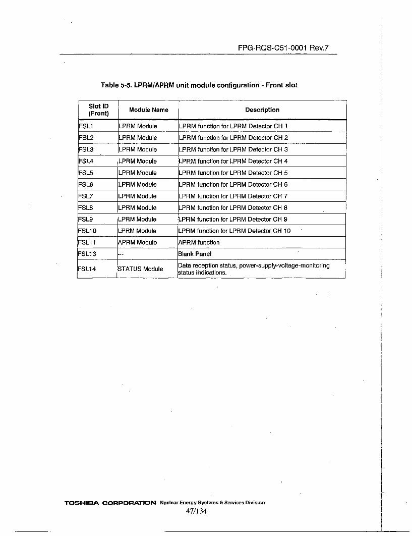
FPG-RQS-C51 -0001 Rev.7
Table 5-5. LPRM/APRM unit module configuration - Front slot
Slot ID(rn) Module Name Description
(FrontMdle LR)fnto frLRMDtctrC
FSL1 LPRM Module LPRM function for LPRM Detector CH 2
FSL3 LPRM Module LPRM function for LPRM Detector CH 3
FSL3 LPRM Module LPRM function for LPRM Detector CH 4
FSL5 LPRM Module LPRM function for LPRM Detector CH 5
FSL6 LPRM Module LPRM function for LPRM Detector CH 6
FSL7 LPRM Module LPRM function for LPRM Detector CH 7
FSL8 LPRM Module LPRM function for LPRM Detector CH 8
FSL8 LPRM Module LPRM function for LPRM Detector CH 9
ESL9 LPRM Module LPRM function for LPRM Detector CH 10
ESL1 1 APRM Module ,PRM function
FSL13 -- Blank Panel
-SL1 4 STATUS Module Data reception status, power-supply-voltage-monitoringstatus indications.
TOSHI-BA CORPORATION Nuclear En~ergy Systems & Services Division47/134

FPG-RQS-C51 -0001 Rev.7
Table 5-6. LPRMJAPRM unit module configuration - Back slot
SoID Module Name Description(Back) _________
.- LVPS Module +5V and ±1 5V power supply to each module
BSL1 AC Module Analog outputs of LPRM levels (Oh. i to 10), APRM level,APRM Upscale (High) setpoint, Simulated Thermal Power
level, and Simulated Thermal Power Upscale setpoint to theprocess computer (0 to 1 60mV / 0 to 125%)
BSL2 AC Module ,nalog outputs of APRM level and APRM Upscale (High)setpoint to the recorder (0 to + VIV/0 to 125%)
BSL3 AC Module &nalog outputs of LPRM levels (Oh. 1 to 10) and APRM level:o the Transient Monitor (1 to +5V / 0 to 1 250/)
BSL4 DIO Module !Digital outputs of LPRM Upscale, Downscale, Inoperable, and
various APRM trip signals to the trip auxiliary unit_______________Digital inputs of reactor mode and APRM bypass signal.
BSL5 RCV Module Optical data reception of the recirculation flow values from theFLOW units
Optical data reception of LPRM levels (Oh. 11 to 22),Inoperable, and LVPS failure information from the LPRM unit
BSL6 --- Blank panel
BSL7 -- Blank panel
B•SL8 TRN Module Optical data transmission of LPRM level (Oh. 1 to 22), APRMlevel, Recirculation FLOW values, Simulated Thermal Powerlevel, APRM Upscale (High) setpoint and Simulated ThermalPower Upscale setpoint to RBM unit
___ LVPS Module +5V and ±1 5V power supply to each module
TOSHIBA CORPORATION Nuclear Energy Systems & Services Division48/134
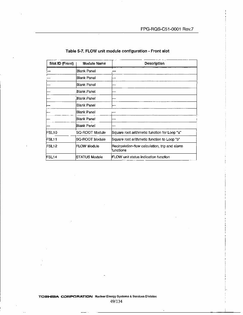
FPG-RQS-C51 -0001 Rev.7
Table 5-7. FLOW unit module configuration - Front slot
Slot ID (Front) Module Name Description
--- ~Blank Panel--
--- ~Blank Panel--
--- ~Blank Panel--
--- ~Blank Panel--
--- ~Blank Panel--
--- ~Blank Panel--
.-- ~Blank Panel--
--- ~Blank Panel--
--- ~Blank Panel--
!FSL1 0 SQ-ROOT Module Square root arithmetic function for Loop"a"
FSL1 1 SQ-ROOT Module Square root arithmetic function to Loop "b"
FSL1 2 FLOW Module Rlecirculation-flow calculation, trip and alarm•unctions
FSL14 STATUS Module JFLOW unit status indication function
TOSHIBA CORPORATION Nuclear Energy Systems & Services Division49/134

FPG-RQS-C51 -0001 Rev.7
Table 5-8. FLOW unit module configuration - Back slot
SoID Module Name Description(Back)
PSSL1 LVPS Module +5V and ±1 5V power supply to each module
BSL1 AO Module Analog outputs to the process computer.
BSL2 AO Module Analog outputs to the recorders.
BSL3 AO Module Analog outputs to the transient monitor.
BS4 DIO Module Digital. outputs of the trip signals to the trip auxiliary unit.
Digital input of Bypass signal.
BSL5 Blank --
BSL6 Blank ---
BSL7 TRN Module Optical serial transmission to RBM unit
BSL8 TRN Module Optical serial transmission to APRM unit
PSSL2 LVPS Module +5V and ±1 5V power supply each module
TOHIBA CORPORATION. Nuclear Energy Systems & Services Division
50/134

FPG-ROS-C51 -0001 Rev.6
Xj//////'At"Y'j'A Recorder
AObue Ccnpter/ • Trip
/ dul fflJlMode
LPRM/APRM Un it
Th" Module with safety function
Fi~qure 5-1 Flow channel & APRM channel Canficiuration
TRN Module: Transmit Optical SignalRCV Module: Receive Optical Signal
LVPS Module: Low Voltage Power
Supply.
DIO Module: Input/Output digital
signals
STATUS Module: Indicate status in
unit
ETOSHIBA CORPORATION Nuclear Energy Systeme & Servicee Divieiee
51/134

FPG-RQS-C51 -0001 Rev.7
5.2.3. Module Requirements5.2.3.1 General
All modules/units shall meet or support the general requirements described in Section5.2.1 and 5.2.2.
The following sections describe the requirements for each module type.
5.2.3.2 LPRM module
The LPRM module generates LPRM level, which is proportional to the neutron fluxlevel.
The LPRM module shall be capable of accepting a 0 to 3 mA current signal from thedetector, and convert the electric current signal to the voltage signal. Then, the LPRMmodule shall apply a low pass filter for anti-aliasing and high frequency noise rejectionto the voltage signal. The low pass filter has the following characteristics:
Type: [a]aStopband: [ ]A_+[ •
The filtered voltage signal is converted to a digital value, a moving average digital filtershall be applied to eliminate the power supply noise. The digital filter has thefollowing characteristics:
Passband: [ ]•izPassband Fluctuation: [ ]1dBStopband: above[ ]I14zStopband Attenuation: more thanE ]Th
more thanE ]dB for[ ]fNumber of Samples for averaged group: [ ]°'Sampling Cycle: [ ]iiiicrosecondsOutput Cycle: [ ]•Iiliseconds
LPRM gain compensations shall be provided for each LPRM input. It shall bepossible to enter simulated "LPRM gain" value manually from the LPRM module frontpanel, where LPRM gain is LPRM detector current at 100% power (40 to 2400p.A).
Full design input range of the LPRM current shall be 0 to 125%.
The LPRM module shall supply power to the LPRM detectors at least 3 mA at 100VDC.
The LPRM module shall be designed to generate the following signals:
(a) LPRM levelLPRM level signals are transmitted to the APRM module.
TOSHIBA CORPORATION Nuclear Energy Systems & Services Division
52/134

FPG-RQS-C51 -0001 Rev.7
(b) LPRM UpscaleThe LPRM module shall be designed to provide an upscale alarm when theLPRM level exceeds the user defined setpoint.The setpoint shall be adjustable over the range corresponding to the 5.0% upto 125.0% flux.
(c) LPRM DowuscaleThe LPRM module shall be designed to provide a downscale alarm when theLPRM level falls below user defined setpoint.The setpoint shall be adjustable over the range of 0.0 to 10.0% flux.
(d) LPRM inoperable signalThe LPRM module shall generate the LPRM inoperable signal if any of thefollowing occur:* The operation mode is not "OP"* The LPRM module is being initialized* One or more FPGAs halt* An error detected in the memory storing LPRM gain value* High voltage power supply fails
The LPRM module front panel shall display following signals:
0a LPRM levelb LPRM Upscalec LPRM Dowascaled LPRM Inoperable
When the LPRM module mode switch is in the "OP" position, the following, asminimum, shall be displayed when requested by the user:
a [Delete]b The LPRM gainc High Voltage monitoring value, Input current monitoring valued Alarm setpoints
When the LPRM module mode switch is not in the "OP" position, the following; asminimum, shall be displayed when requested by the user:
a Apply the LPRM gain adjustmentsb Alarm trip checks (LPRM alarm outputs)
The operation clock of LPRM module ist )-I~z.
TOSHIBA CORPORATION Nuclear Energy Systems & Services Division
53/134

FPG-RQS-C51 -0001 Rev.7
5.2.3.3 APRM module
The APRM module receives data from the LPRM modules mounted in the sameLPRM/APRM unit through the TRN module, and from the LPRM modules mounted in theLPRM unit, as well as the FLOW modules through the RCV module.
The dual electrical communication links are used in the data transmission from the TRNand RCV modules. The link consists of the primary link and the secondary link. TheAPRM module receives data though the primary link usually, and when the primary link ismarked as failed, the APRM module uses the secondary link.
The APRM module shall verify that the periodic data transmissions occur in the electricalcommunication links to determine if the links are failed. In addition, for each datatransmission over the fiber optic cables, the APRM module receives alarms from the RCVmodule if a failure occurs, and uses this alarm to determine if the links are failed.
The APRM module calculates the APRM level in the reactor core based on the LPRMlevels.
If the APRM level exceeds setpoints, the APRM module generates trip signalscorresponding to each seipoint.
APRM module shall be designed to generate the following signals:
(a) APRM level
The APRM module shall calculate the APRM level using the following formula:
- LPRM _level,
APRM _ level = - x APRM _GAINLPRM _COUNT
Where,APRM_level: Average power level 0.0 - 125.0%LPRM~level•: i-the LPRM level 0.0 - 125.0%APRM_GAIN: APRM gain 1.00 - 3.00LPRM_COUNT: Number of operable LPRM modules. The APRM
module calculates this value from each LPRMinoperable signal.
The APRM gain shall be adjusted by entering the APRM gain value manuallyfrom the APRM module front panel.The APRM level and the APRM_GAIN shall he displayed on the APRM modulefront panel if requested.
(b) Simulated Thermal Power LevelThe APRM module shall calculate the Simulated Thermal Power Level of thereactor core as the first order lag of the APRM level by applying 0.00 -. 9.99second time constant. The time constant can be set with a rotary switch andshall be stored in the dual storage.
TOSHIBA CORPORATION Nuclear Energy Systems & Services Division
54/134

FPG-RQS-C51 -0001 Rev.7
The Simulated Thermal Power Level and the time constant shall be displayed onthe APRM module front panel if requested.
(c) Average Power Level for APRM Upscale (High)The APRM module shall calculate the Average Neutron Flux for APRM Upscale(High) alarm as the first order lag of the APRM level by applying 0.00 - 9.99second time constant. The time constant can be set with a rotary switch andshall be stored in the dual storage.
(d) Flow biased Simulated Thermal Power Upscale SetpointThe flow biased Simulated Thermal Power Upscale setpoint shall be calculated asfollows:
Simulated Thermal Power Upscale Setpoint = (Slope X Flow) + Offset
Where,
Slope Slope of the Power/Flow level line, 0.40 - 1.50Flow Recirculation flow, 0.0 - 125.0% (The lower of the
two Flow values received from the two FLOW units.Offset flux offset at zero flow, 20.0 to 125.0%
When the calculated Simulated Thermal Power Upscale setpoint exceeds 115 %,the setpoint is clamped to 115%.
The slope, offset, and the clamp value shall, be displayed on the APRM modulefront panel if requested.
(e) Flow biased APRM Upscale (High) SetpointWhen the reactor mode switch is in the "RUN" position, the flow biased APRMUpscale (High) shall be calculated as follows:
APRMV Upscale (High) Setpoint = (Slope× Flow) + Offset
Where,
Slope Slope of the Power/Flow level line, 0.40 to 1.50Flow Recirculation flow, 0.0 - 125.0%Offset flux offset at zero flow 20.0 to 125.0%
When the calculated APRM Upscale (High) setpoint exceeds 108%, the setpoinatclamped to 108%.
TOSHIEBA CORPORATION Nuclear Energy Systems & Services Division
55/134
FPG-RQS-C51 -0001 Rev.7
The slope, offset, and the clamp value shall be displayed in the APRM modulefront panel if requested.
(f) APRM Upscale (High-High)The APRM module shall be designed to provide an APRM Upscale (High-High)trip signal to the RPS when the APRM level exceeds the user defined setpoint.There are two setpoints depending on the position of the reactor mode switch.One setpoint shall be adjustable over the range of 40.0 to 125.0% APRM levelwhen the reactor mode switch is in the "RUN" position.The other setpoint shall be adjustable over the range of 6.0 to 20.0% APRM level,when the reactor mode switch is not in the "RUN" position.
Both setpoints shall be displayed on the APRM module front panel if requested.
(g) Simulated Thermal Power UpscaleThe APRM module shall be designed to provide an Simulated Thermal PowerUpscale trip signal to the RPS when the Simulated Thermal Power Level exceedsthe setpoint described in (d) of this section.
(h) APRM Upscale (High)The APRM module shall be designed to generate an APRMv Upscale (High)alarmsignal intended to be used as a rod block when the APRMv level exceeds theAPRM Upscale (High) setpoint described in (e) and the reactor mode switch is inthe "RUN" position.
The APRM Upscale (High) alarm signal is generated when APRM level exceedsthe user defined setpoint and the reactor mode switch in not in the "RUN"position. The alarm setpoint shall be adjustable over the range of 6.0 to 20.0%APRM level.
(i) APRM DownscaleThe APRM module shall be designed to generate a downscale alarm signalintended to be used as a rod block when the APRM level falls below a userdefined setpoint.The alarm setpoint shall be adjustable over the range of 2.0 to 10.0% APRMlevel.
The setpoint shall be displayed on the APRM module front panel if requested.
(I) APRM InoperableThe APRM module shall provide an inoperable trip signal to the RPS when anyof the following conditions occur:
a. One or more signal processing FPGAs haltb. The APRM module's mode switch is not in the "OP" positionc. The APRM module is being initializedd. The number of operable LPRM modules is less than the set value
TOSHIBA CORPORATION Nuclear Energy Systems & Services Division
56/1 34
FPG-RQS-C51 -0001 Rev.7
"The minimum number of LPRM modules" set value shall be displayed on theAPRM module front panel if requested.
(k) SRI Simulated Thermal Power UpscaleThe APRM module shall be designed to generate a SRI Thermal Power UpscaleTrip signal intended to be used as a Selected Rod Insertion signal when theSimulated Thermal Power Level exceeds a user defined setpoint.The alarm setpoint shall be adjustable over the range of 0.0 to 40.0% thermal
power.
The setpoint shall be displayed on the APRM module front panel if requested.
(1) SRI Recirculation Flow DownscaleThe APRM module shall be designed to genereate a SRI Recirculation FlowDownscale Trip signal to be used as a Selected Rod Insertion signal when theRecirculation Flow value falls below a user defined setpoint.The alarm setpoint shall be adjustable over the range of 35.0 to 70.0% flow.
The setpoint shall be displayed on the APRMV module front panel if requested.
(in) APRM Minor FailureThe APRM module shall generate a Minor Failure alarm when any one of thefollowing conditions occur:
a. An error is detected in the EEROM storing the APRM gain.b. A time-out error is detected in the data transmission from the TRN
module.c. A time-out error is detected in the data transmission from the LPRM
units.d. A time-out error is detected in the data transmission from the FLOW
units.e. One or more Human Machine JInterface (HML) FPGAs halt.
The APRM module front panel shall display the following signals:
* Trip and Alarm signals of (f), (g), (h), (i), (j), (k), (1), and (in)
* Chronological order of an APRM Upscale (High-High) trip and a SimulatedThermal Power Upscale trip
* Reactor mode switch status, i.e. if the mode switch is in "RUN" position
When the APRM module mode switch is in the "CAL" position, the following, as aminimum, shall be made available when requested bY the user:
* APRM gain adjustment* Trip and Alarm checksK
TOSHIBA CORPORATION Nuclear Energy Systems & Services Division
57/ 134

FPG-RQS-C51 -0001 Rev.7
* Setting of trip setpoints
The operation clock of APRM module is[ 11H-z.
5.2.3.4 SQ-ROOT module
The SQ-ROOT module calculates the recirculation loop flow from the differentialpressure value obtained from the differential pressure transmitter.The SQ-ROOT module shall provide at least 20mA at 24 VDC to the differentialpressure transmitter.
The SQ-ROOT module shall be designed to generate the following signals:
(a) Differential Pressure ValueThe SQ-ROOT module shall receive a 4-20 mA differential pressure signal fromthe differential pressure transmitter, and applying the analog-to-digital converterand the first order lag filter. The time constant of the filter is adjustable in the range0.00 - 9.99 seconds.
(b0) Loop Flow ValueThe SQ-ROOT module shall calculate the recirculation loop flow from the filtereddifferential pressure value as follows:
Flow=125.0x (APlfb)
Where,Flow: Loop Flow Value. It is normalized in the range 0 to 125%zAP: Differential Pressure Value calculated in (a)Th Offset corresponding to 4mA input signalIf Constant corresponding to 16mA input signal
(c) Input signal low alarmThe SQ-ROOT module shall generate the input signal low alarm if the differentialpressure value calculated in (a) falls below the setpoint.
(d) SQ-ROOT inoperable signalThe SQ-ROOT module shall generate the inoperable signal if the following occur:* Input signal low alarm is generated* One or more signal processing FPGAs halt
(e) SQ-ROOT Minor Failure alarmThe SQ-ROOT module shall generate the Minor Failure alarm if the HMI FPGAhalts.
The SQ-ROOT module front panel shall display the following signals.
TOSHIBA CORPORATION Nuclear Energy Systems & Services Division
58/134
FPG-RQS-C51 -0001 Rev.7
• Differential pressure value* Loop Flow value* Operation mode* Inoperable signal* Minor failure signal alarm
It shall be possible to enter simulated differential pressure signals to the SQ-ROOTmodule for calibration.
The operation clock of SQ-ROOT module is [lI-Iz.
5.2.3.5 FLOW moduile
The FLOW module computes a recirculation flow value from the two SQ-ROOTmodules, one of which measures the recirculation loop A, and the other of whichmeasures the recirculation loop B. The range of the recirculation flow value is 0 to125%. The computed total recirculation flow value is transmitted to the LPRM/APRMunits and the RBM units. When the recirculation flow value exceeds the setpoint, theFLOW module shall generate the recirculation flow value high alarm.
(a) Recirculation flow valueThe FLOW module shall calculate the total recirculation flow value using thefollowing equation:
FLOW= (Flow-A + Flow-B) X FLOW GAIN
Where,
FLOW Recirculation flow valueFlow-A Loop-A flow valueFlow-B Loop-B flow valueFLOW GAIN Gain 0.5 to 2.0
(b) Recirculation Flow UpscaleThe Flow module generates the recirculation flow upscale alarm when the totalrecirculation flow rate exceeds the user defined setpoint.The setpoint shall be adjustable over the range of 90.0 to 125.0% flow.
(c) Recirculation Flow InoperableThe FLOW module shall provide the recircuration flow inoperable signal if anyof the following conditions occur:
* The FLOW module mode switch is not in the "OP" position.* Either of the SQ-ROOT modules is inoperable.* One or more signal processing FPGAs halt.
(d) FLOW module Minor Failure alarm
"TOSHIEBA CORPORATION Nuclear Energy Systems & Services Divsion
59/134
FPG-RQS-C51 -0001 Rev.7
The FLOW module shall provide the FLOW module Minor Failure alarm if anyof the following occur:
* HMI FPGA halts* Either of the S Q-ROOT modules emits the Minor Failure alarm* A time-out error is detected in the transmission from either of the
SQ-ROOT modules.
The FLOW module front panel display shall display the following signals:
* Total flow rate value ( see (a).)• Bypass status* Operation mode* Inoperable signal (see (c).)* Minor failure alarm ( see (d).)
a~c
The operation clock of the FLOW module is[ ]MHz.
5.2.3.6 AO module
The AO module has up to 16 analog output ports. The AO module receives digital datafrom the unit middle plane, converts the digital data to analog data. Photo couplers and
isoltedtypeD~iC coverersisolate the unit from the output ports.
There are eight types of AO modules:
5.2.3.6.1 AO module 1
This type of the AO module shall be mounted in the LPRM unit, and provide the analog
signals to Process Computer as described in Section 5.2.2.1.
5.2.3.6.2 A0 module 2
This type of the AO module shall be mounted in the LPRM/APRM unit, and provide theanalog signals to Process Computer as described in SectiOn 5.2.2.2.
5.2.3.6.3 AO module 3
This type of the AO module shall be mounted in the LPRM/APRM unit, and provide the
analog signals to Recorder as described in Section 5.2.2.2.
5.2.3.6.4 AO module4
This type of the AO module shall be mounted in. the LPRM Unit, and provide the analogsignals to Transient Monitor as described in Section 5.2.2.1.
TOSHIBA CORPORATION Nuclear Energy Systems & Services Division
60/134

FPG-RQS-C51 -0001 Rev.7
5.2.3.6.5 AO module5
This type of the AO module shall be mounted in the LPRMIAPRM unit, and provide the
analog signal to Transient Monitor as described in Section 5.2.2.2.
5.2.3.6.6 AO module6
This type of AO module shall be mounted in the FLOW unit, and provide the analogsignal to Process Computer as described in Section 5.2.2.3.
5 .2 .3 .6.7 AO module7
This type of AO module shall be mounted in the FLOW unit, and provide the analogsignal to Transient Monitor as described in Section 5.2.2.3.
5.2.3.6.8 AO module8
This type of AO module shall be mounted in the FLOW unit, and provide the analogsignal to Recorder as described in Section 5.2.2.3.
5.2.3.7 DIO module
The discrete input and output module has 16 output ports and 4 input ports. The DIOmodule receives discrete signals from the unit middle plane in the unit and transmitthem to external equipment, and receives discrete signals from external equipment.
Photo couplers isolate the unit and other modules from the output and input ports.
There are two types of the DIO module.
5.2.3.7.1 DIO module 1
This type of the DIO module is mounted in the LPRM unit, and provides the discreteI outputs described in Section 5.2.2.1 to the trip auxiliary unit.
5.2.3.7.2 DIO module 2
This type of the DJO module is mounted in the LPRM/APRM unit, and provides thediscrete outputs to the trip auxiliary unit, and receives discrete inputs as described inSection 5.2.2.2.
5.2.3.7.3 DIO module 3
This type of the DIO module is mounted in the FLOW unit, and provides the discreteoutputs to the trip auxiliary unit, and receives discrete inputs as described in Section5.2.2.3.
TOSHIBA CORPORATION Nuclear Energy Systems & Services Division
61/134

FPG-RQS-C51 -0001 Rev.7
5.2.3.8 TRN module
The TRN module collects digital signals from other modules in the unit, multiplexesthem in the defined frame format, and transmits the frame to the LPRM/APRM unit orexternal equipment through the fiber optical cables. The TRN modules are mounted inthe FLOW unit and APRM units.
Each TRN module has two separate, independent data processing paths. Each of thedata processing paths has two outward communication links, transmitting identical data.One of the links is used as the primary, and the other is used as the secondary.
The TRN module has the two watchdog timers that monitors the periodic operation ofthe FPGAs. If the watchdog timer detects the failure of the FPGAs, the front panelLED shall light for each data processing path.
The operation clock of TRN module is [ •I-z.
The TRN module has three operational modes corresponding to the unit type on whichit is mounted.
5.2.3.8.1 In the LPRM unit
The TRN module collects LPRM levels and the LPRM inoperable signals, andtransmits them to the LPRM/APRM unit as described in Section 5.2.2.1.
5.2.3.8.2 In the LPRM/APRM unit
When the TRN module is mounted in the LPRM/APRM unit, it has following two
functions:* The TRN module collects the LPRM levels and the LPRM inoperable signals
from the LPRM modules in the LPRM/'APRM unit, and transmits them to theAPRM module over the middle plane wiring.
* The TRN module collects signals and transmits them to the Rod Block Monitor asdescribed in Section 5.2.2.2.
5.2.3.8.3 In the FLOW Unit
The TRN module collects signals and transmits them to the LPRM/APRM unit as
described in Section 5.2.2.3.
5.2.3.9 RCV module
The RCV module is mounted in the LPRM/APRM unit. The RCV module receivesthe data from the TRN modules in the LPRM unit, and provides them to the APRMmodule.
"TIOSHIBA CORPORATION Nuclear Energy Systems & Services Division
62/134

FPG-RQS-C51 -0001 Rev.7
An RCV module has four separate, independent optical1receivers, each of which receivesserial data at 1 megabit per second (Mbps) every [ ]fi~lliseconds from a TRN module bya one way fiber optic cable. The RCV module sends the received data in the same frameformat over the copper lines inside the unit.
The RCV module checks for the periodic data transmission through each fiber optic cable.IIf the RCV module fails to receive the three consecutive data frame for[ ]fnllsecondper cycle ([ ]nfiillisecond cycle time plus some margin), the RCV module marks the linkfailed.
a,c
The RCV module checks for the parity bit on every[ ]bit word in the received data througheach fiber optic cable.
The RCV module has one watchdog timer that monitors the periodic operation of theFPGAs. The watchdog timer detects a failure of the FPGAs.
The operation clock of RCV module is[r ]R•Hz.
5.2.3.10 LVPS module
The LVPS module supplies +5VDC,+_ 15VDC to the other modules in the unit.
5.2.3.11 STATUS module
The STATUS module displays the status of other modules on the front panel. There aretwo types for LPRM unit, LPRM/APRM unit and FLOW unit.
The STATUS module has a watchdog timer that monitors the periodic operation of itsHMI FPGA. If the watchdog timer detects the failure of the FPGA, it shall beindicated on the front panel.
The operation clock of STATUS module is ['Nz.
5.2.3.11.1 STATUS module 1
This type of the STATUS module is mounted in the LPRMIAPRM unit and display thefollowings:
- LVPS alarm Indicate that either of the LVPS module fails- Fail Indicate if either of the LVPS module fails, or any one of the
LPRM or FLOW module fails, or the FPGA of the STATUSmodule halts.
-LINE status Status of the following data transmission:(a) From the TRN module in the LPRM/APRM unit to the
APRM module(b) From the LPRM unit to the LPRM/APRM unit(c) From the FLOW units to the LPRM/APRM unit
TOSHI-BA CO3RPORATIOIN Nuclear Energy Systems & Services Division
63/134

FPG-RQS-C51 -0001 Rev.7
(a) and (b) are dual transmission.
5.2.3.11.2 STATUS module 2
This type of the STATUS module is mounted in the LPRM or FLOW units, and displaythe followings:
-LVPS alarm- Fail
Indicate that either of LVPS module failsIndicate if the FPGA of the STATUS module halts, or both ofthe LVPS module fail.
5.2.3.12 BLANK Module
The BLANK module shall be mounted in the LPRM unit or the LPRM/APRM unit as adummy LPRM module. The BLANK module provides the mock normal signals forthe LPRM Inoperable signal, the LPRM Upscale alarm, and the LPRM Downscalealarm, in order to prevent false alarms, because the LPRM or LPRM/APRM unitgenerates an alarm by ORing all LPRM modules and the BLANK modules for thosealarms.
5.2.4. General Design5.2.4.1 Chassis Requirements
Chassis that are used as the enclosure of the units must be suitable for mounting in astandard 19 inch rack, and must have adequate strength and provide positive hold downfor the modules. Chassis are fixed in the rack with 4 screws in the front side and 8screws in the backside. The torque to tighten the screws in the front side is 2.6 - 3.4 N-
m, inthe backside is 1.3 - 1.7 N-m.
Outline dimension(Excluding protrusion)
Weight(Excluding built-in)Material
177 mm482.6 mm440.8 mm19 kg orlessAluminum
HeightWideDepth
The use of extender is permitted and, if needed, shall be included as part of thequalification testing.
The side plate of chassis must have sufficient strength and to meet seismic requirementsspecified in Section 5.5.2.
5.2.4.2 System Cables and Connectors
TOSHIBA CORPORATION Nuclear Energy Systems & Services Division
64/134

FPG-RQS-C51 -0001 Rev,7
1. The PRM System shall include all cabling and wiring necessary to connect andoperate the units (and the system).
2. All cables and connectors shall not contain any polyvinyichloride (PVC).
3. [Delete]4. All cables shall be suitable for UL Class 2 service. Specifically, withstand rating
shall be more than 3 times the signal level voltage or 150 volts.
5. Temperature rating shall be 60'C or greater.
5.2.4.3 Data Retention Capability Requirements
Any EEPROM used for field modifiable constants shall be capable of at least 100,000write cycles.
5.2.4.4 Transferring information between modules in the same unit
1. Each unit of the PRM System shall be capable of transferring information betweenmodules in the same unit.
2. Failures of other units shall not defeat the concerned unit's capability to transfer datain the concerned unit.
3. Loss of power to one module shall not defeat the capability of other modules in thesame unit.
4. [Delete]5. Surge withstand capability shall be included as given in Section 5.5.4.
5.2.4.5 Grounding/Shielding Requirements
The PRM System shall meet IEEE 1050 and EPRI TR-102323 grounding requirements.This includes supporting connection to single point, multi-point and floating groundsystems, and providing a ground connection point on each chassis.
The PRM System shall meet IEEE 1050 and R.G. 1.180 shielding requirements. Thisincludes providing shielding connection points for the 1I/0 module field terminations.
5.2.4.6 Termination Requirements
Features shall be provided to substitute test signals or monitoring instruments for field
connections.
Any connectors and terminations to the units shall be included in qualification testing.
5.2.4.7 Requirements for the power supply lines
TOSHIBA CORPORATION Nuclear Energy Systems & Services Division
65/134
FPG-RQS-C51 -0001 Rev.7
Varistors and noise filters shall be inserted in the power supply lines of each LP•RM,ILPRM/APRM, and FLOW unit as provisions for surge withstand. Following varistorsand noise filters shall be applied:
* Varistor (between line for AC connection and ground):[ ]'[ I or the equivalent one.
* Varistor (between neutral for AC connection and ground)Jj7'[ •rthe equivalent one.
• Varistor (between line and neutral for AC connection):[ I,'c[I ]r the equivalent one.
* Noise Filter (between line and neutral for AC connection).{]the equivalent one.
5.3 Software Requirements
1. The baseline configuration of the qualified units shall be controlled by NED itself.All modules and units shall be marked with an identifier that includes revision level.
2. The Software integrity level required for the safety-related functions of the unitsshall be integrity level 4.
3. FPGA based units application logic shall be designed in VHDL, which is a hardwaredescription language.
4. Application logic shall be modular in structure and shall employ structured[ programming.
5. The logic capacity of FPGA shall be sufficient to execute application logic.6. The application logic contained in the FPGA shall not be rewritable. Therefore,
non-rewritable FPGA type shall be used.7. As long as the system is normal, the non-rewritable FPGA shall retain the logic.
8. NICSD shall specify the FPGA availability.9. Functional Elements (FE) shall be used to program the FPGA. Only FEs that are[ completely tested (by exhaustive pattern testing), shall be used in the FPGA design.
10. Any memory used for field modifiable constants shall be capable of at least 100,000write cycles.
S11. The application logic shall provide the features required for the satisfactory systemperformance.
12. The self-test function shall determine the specific failures of any module within thesystem for its replacement.
13. Verification and Validation Requirements:
A. NICSD shall have a V&V Plan for the PRM logic design.B. NICSD shall take a life cycle approach to PRM logic design development, with
TOSHIBA CORPORATION Nuclear Energy Systems & Services Division
66/134
FPG-RQS-C51 -0001 Rev.7
V&V activities performed throughout the life cycle.S C. The PRM logic design requirements shall be documented to be reviewable for
completeness, correctness and consistency.S D. NICSD shall provide traceability of software requirements throughout the life
cycle.E. There shall be both functional and structural testing of the PRM logic design.
F. NED shall evaluate the NJCSD's V&V program plan against the followingdocuments:(1) Section 5.3.4 of IEEE Standard 7-4.3.2
(2) IEEE Standard 1012
(3) NED's V&V PlanG. If NICSD 's V&V processes do not meet requirements applicable to Nuclear
Power Plants, then compensatory measures shall be implemented.
14. Commercial digital equipment shall be controlled in accordance with applicablecommercial grade dedication process.
I 15. Software tools shall be identified within the logic design development process.V&V tasks of witnessing, reviewing, and testing are not required for software tools,
] but are provided for the software that is produced using the tools is subject to V&Vactivities that will detect flaws introduced by the tools. Software tools shall beidentified and controlled under configuration management.
16. Digital equipment qualification testing shall be performed with each requiredfunctions and each diagnostic functions as specified in Section 5.1.6.
17. The test and calibration as specified in Section 5.1.6 shall not adversely affect theability which the digital equipment performs its safety function as specified inSection 4.1.2.
18. Data communication between units or with other safety and non-safety systems shallnot inhibit the performance of the safety function as specified in 4.1.2.
19. The PRM System application logic shall be developed to meet all softwarestandards and codes in accordance with the design process specified in the SoftwareQuality Assurance Plan (SQAP).
20. NICSD shall ensure upward compatibility, maintain the same or enhanced level ofrigor in the processes.
21. NICSD shall ensure to maintain continuously the same versions of software tools, orcapability to reconstruct same functionality with the revised tools.
5.4 Design Life
SThe design goal of the qualified life for the system shall be 15 years, consideringThe material and equipment selection for the system components are based on a 15 yeardesign life, with appropriate provisions for maintenance and replacement. Reparabilityis enhanced by the modular design of PRM electronic equipment. Channel redundancy
Sand bypass capabilities are provided in PRM design; hence, failed components can bereplaced with little or no effect on system operation.
TOSHIBA CORPORATION Nuclear Energy Systems & Services Division
67/134

FPG-RQS-C51 -0001 Rev.7
The safety-related components are repaired or replaced as they fail but completed withinthe times allowed by the plant Technical Specifications. All PRM instruments (notincluding sensors) in the Main Control Room are designed such that they can bemaintained, tested and calibrated during normal plant operation without the adverseplant shutdown or scram.
SA periodic surveillance and maintenance interval shall be determined per IEEE Std 323to account for any significant aging mechanisms.
TOSHIBA CORPORATION Nuclear Energy Systems & Services Division
68/134

FPG-RQS-C51 -0001 Rev.7
5.5 Environmental Conditions5.5.1 Environmental Requirements
The PRM System shall not oniy operate within the normal environmental condition inthe located area, but also within the abnormal environmental conditions of anticipatedtransients and accidents, in order to preserve the safety system functions.
The PRM System will be located in a mild environment such as the main control room,so only mild environment condition is considered in this specification. Table 5-Ishows the environmental conditions.
Table 5-1 Environmental Conditions
Normal Environmental Abnormal Environmental
Temperature Range 16 to 40°C 4 to 50°CHumidity Range 40 to 95% 10 to 95 %
___________ (non-condensing) -(non-condensing)
Radiation Exposure* Up to lOGy Up to lOGyEPRI TR- 107330 requirements
* Section 6.3 (Table 6.6) of EPRI TR-1005 16, Nuclear Power Plant EquipmentQualification Reference Manual, provides a basis for the specified 1 kRAD or 10 Gyradiation exposure level. Section 6.3 of EPRI TR-100516 further defines the 1 kRADexposure level as the gamma 40-year dose from normal/abnormal service(approximately 2.9 millirem per hour). In this specification, SI units should be used.So here, 10 Gy radiatioii exposures is shown.Radiation exposure is a rate phenomena, so the difference of the exposure rate willcause the different aging effects on the test specimen even if the integral doses were thesame. However, the radiation exposure rate as shown in TR- 100516 is too low tosimulate the condition at the qualification testing.The higher-level exposure rate will cause the severer aging effects to the test specimen.So the higher level exposure rate will provide the safety side simulation of the radiationaging. Hence we provide only the integral exposure level here, because the exposuretimes in any realistic qualification tests are shorter than 40 year.
[.The environmental qualification shall follow the requirement of RG 1.89 and IEEE Std323 to assure that the instrument is able to complete its safety function under the those
]conditions of Table 5- 1.
PRM units shall operate for the temperature/humidity proffle given in Figure 5-2.
TOSHIBA CORPORATION Nuclear Energy Systems & Services Division
69/134
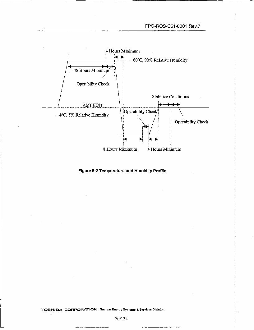
FPG-RQS-C51 -0001 Rev.7
4 Hours Minimum
600C, 90% Relative Humidity
Stabilize Conditions
40C, 5% Relative Humidity
Check
8 Hours Minimum 4 Hours Minimum
Figure 5-2 Temperature and Humidity Profile
TOSHIBA CORPORATION Nuclear Energy Systems & Services Division
70/134
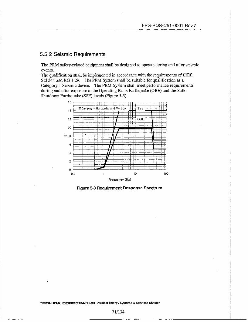
FPG-RQS-C51 -0001 Rev.7
5.5.2 Seismic Requirements
The PRM safety-related equipment shall be designed to operate during and after seismicevents.The qualification shall be implemented in accordance with the requirements of TREEEStd 344 and RG 1.29. The PRM System shall be suitable for qualification as aCategory 1 Seismic device. The PRM System shall meet performance requirementsduring and after exposure to the Operating Basis Earthquake (OBE) and the SafeShutdown Earthquake (SSE) levels (Figure 5-3).
16 -
5%Damping - Horizontal and Vertical SE14
.10
OBE __
1 10 100
Frequency (Hz)
Figure 5-3 Requirement Response Spectrum
V
TOSHIBA CORPORATION Nuclear Energy Systems & Services Division
71/1 34

FPG-RQS-C51 -0001 Rev.7
5.5.3 EMI/RFI Requirements
The PRM units shall be design to minimize susceptibility to, and generation of theelectromagnetic interference (EMIT) and radio frequency interference (RFI).The PRM units shall be subjected to test for EMI/RFI conditions that conform to theguidelines given in RG 1.180.
When subjected to this level of EMI/RFI, any PRM unit shall continue to function asfollows:
a. The transfer of 1/0 data shall not be disrupted.b. The emissions shall not cause the discrete I/O to change state.c. Analog I/O levels shall not vary more than 2 %.
For convenience, Figure 5-4 through 5-10 has been reproduced in this document fromoriginal RG 1.180 requirement, therefore it is required to consult the originals whenthese tests are executed.
5.5.3.1 Low-Frequency Conducted Susceptibility Testing got AC Power Leads(Cs 101)
The PRM units shall not be susceptible to a test signal with levels as specified in Figure5-4 that complies with RG. 1.180 Section 4.1.1. This test is performed for evaluating theconducted electromagnetic transients injected on power input leads over a frequencyrange from 30 Hz to 150 kHz. This test shall be perfonned in accordance withMIL-STD-461lE, CS 101.
140 j I l '
120
1111~
Ii Ii tlm
I I~4rirrii -ttI~- ~triiPt-t Kttfii
-3 110._-, o
10
-- JlilbLiili ~NL!tHi~_Voltage source:
• over 28V:#1• not over 28V:#2
!till tl N!lI~jiI 106!~llo.5
90 '.1 tHillil
Ii *~..d. 96.5
~80L : iT I H I e rl1 .00E+01 1 .00E+02 1 .00E+03 1.OOE+04 1.OOE+05 1.OOE+06
Frequency(Hz)
(R.G. 1.180 CS1 01)
TOSHIBA CORPORATION Nuclear Energy Systems & Services Division
72/134

FPG-RQS-C51 -0001 Rev.7
5.5.3.2 High-Frequency Conducted Susceptibility Testing for AC Power Leads(CSl114)
The PRM units shall not be susceptible to a test signal with levels as specified in. Figure5-5 that complies with R.G. 1.180 Section 4.1.2. This test is performed for evaluatingthe conducted electromagnetic transients injected on power input leads over a frequencyrange from 10 kI~z to 30 MiHz. This test shall be performed in accordance withMIL-STD-461E, CS114.
m
-J.4-,
E
120
110
100
90
80
70
60
50
4d,3
30
' (
II
I' IIIII I I
II
i~iI Ii''I. .1
97
1.00E+04 1.00E+05 1.00E+06 1.00E+07 1.00E+08 1.00E+09Frequency(Hz)
Figure 5-5 High-Frequency Conducted Susceptibility Operating Envelopes forPower Leads (R.G.1.180 CS114)
5.5.3.3 High Frequency Conducted Susceptibility Testing for Signal Cable (CSI 14,CSl15, CSl16)
The PRM units shall be designed to withstand radio frequency interference coupledonto the instrument cabling, and shall be tested by following the measurementprocedure CS 114, CS 115 and CS 116 of MIL-STD-461E to meet the requirement ofbeing subjected to a test signal levels 91ldBgiA (frequency range from 10 kHz to 30MHz) (C5l14), 2A (CSl15) and 5A(frequency range from 10kHz to 100Ml~z)(CS116).
5.5.3.4 Radiated Susceptibility, Magnetic Fields (RS 101)
The PRM instruments shall not be susceptible to the electromagnetic field levels asspecified in Figure5-6 that complies with R.&.1.180 Section 4.3.1. This test isperformed in the frequency range of 30 Hz to 100 kHz. This test shall be performed inaccordance with the MIL-STD-461E RS 1O1.
TOSHIBA CORPORATION Nuclear Energy Systems & Services Division
73/134

FPG-RQS-C51 -0001 Rev.7
pa.m-o4)
a,-a4-I
2
190180
170
160
150
140
130
120
110
100
116
1.00E+01 1.00E+'02 1.00E+03 1.00E+04Frequency(Hz)
1.OOE+05
Figure 5-6 Low-Frequency Radiated Susceptibility Envelopes (R.G.1.180 RS1O1)
5.5.3.5 Radiated Susceptibility, Electric Fields (RS 103)
The PRM instruments shall not be susceptible to the electromagnetic field strength of 10V/rn. This test shall be performed at frequency range of 30 MHz to 1 GHz. This testshall be performed in accordance with MIL.-STD-461E, RS 1O3.
5.5.3.6 Low-Frequency Conducted Emissions (CE 101)
The PRM units shall not be susceptible to the electromagnetic emissions specified inFigure5-7 that complies with R.G.-1 .180 Section 3.1. This test shall be performed at thefrequency from 30Hz to 10kHz. This test shall be performedin accordance withMIL-STD-461E, CE101.
TOSHIBA CORPORATION Nuclear Energy Systems & Services Division
74/134
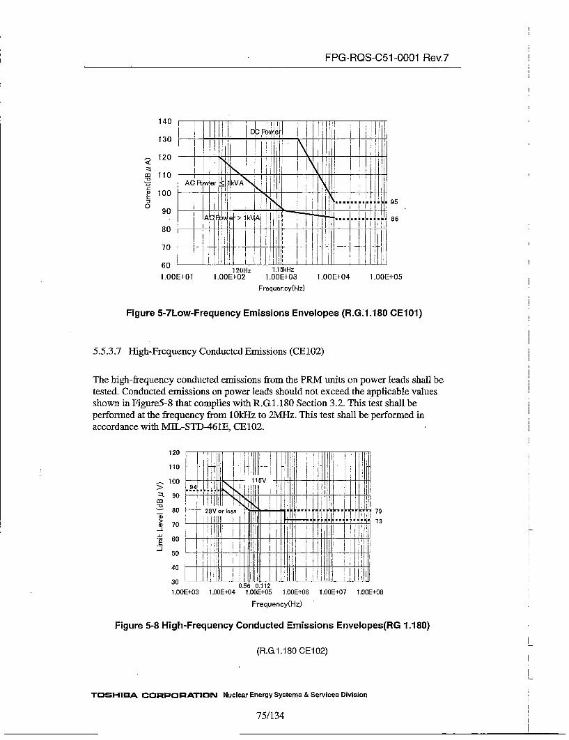
FPG-RQS-C51 -0001 Rev.7
140
130
120
110
100
-~ J~ ___ ~ _____
T'~m
a)
:30 90
80
70
iI
~I~J
I I
IN H~I'iI II
95
: r • f , • r l l , i r T I
A'd~i>ikVAI-~ i1I~~ ............................'.1i J
I, F I~II *1
1 .00E+01120Hz
1.00E+021.15kHz
1 .00E+03 1.00E+04 1.00E+05
Frequency(Hz)
Figure 5-7Low-Frequency Emissions Envelopes (R.G.1.180 CEl01)
5.5.3.7 High-Frequency Conducted Emissions (CE 102)
The high-frequency conducted emissions from the PRM units on power leads shall betested. Conducted emissions on power leads should not exceed the applicable valuesshown in Figure5-8 that complies with R.Gl.180 Section 3.2. This test shall beperformed at the frequency from 10kHz to 2MI-Hz. This test shall be performed inaccordance with MIL-STD-461E, CE102.
m
-o
-J
-4-
...
_..
120
110
100
90
80
70
60
50
40
30
1.00
I]! 115V
L Ii,! IH
28V or less
'III' ilIi I .J.1...4.t ii
Ii I[ I
Ii0.56 0.112
7973
'E+'03 1 .00E+04 1 .O0E+05 1 .00E+06 I .OOE+07 1 .00E+08
Frequency(Hz)
Figure 5-8 High-Frequency Conducted Emissions Envelopes(RG 1.180)
(R.G.1 .1 80 CE1 02)
TOSHIBA CORPORATION Nuclear Energy Systems & Services Division
75/134

FPG-RQS-C51 -0001 Rev.7
5.5.3.8 Radiated Emissions, Magnetic Field (RE101)
The radiated magnetic field emissions from the PRM units shall be tested. Magneticfield emissions should not be radiated in excess of the levels shown in Figure 5-9 thatcomplies with R.G.l.180 Section 3.3. This test shall be performed at the frequency from30Hz to 100kHz. This test shall be performed in accordance with MIL-STD-461E,REI101.
p0.m
C
C-J
E
140 jL t r! ~ 'L~130 li
120 p t110 r r I i i
1.00E+-01 1 .00E+02 1 .O0E+03 1.00E+04
Freq~uency(Hz)
1 .O0E+05 1 .00E+06
Figure 5-9 Magnetic-Field Radiated, Emissions Envelope (R.G.1.180 RE101)
5.5.3.9 Radiated Emissions, Electric Fields (RE102)
The radiated electric field emissions from PRM units shall be tested. Electric fieldemissions should not be radiated in excess of the rms values shown in Figure 5-10 thatcomplies with R.G.l.180 Section 3.4. This test shall be performed at the frequency from2MHz to 1000MHz. This test shall be performed in accordance with MIiL-STD-461E,RE102.
TOSHIBA• CORPORATION Nuclear Energy Systems & Services Division
76/134

FPG-RQS-051 -0001 Rev.7
Io i i ! i ImI
m , I!' I 72
60• H 1 1 F ii~-J I H
20 2 l5 i ! i i : !
1.OOE+04 1.0OE+05 1.DOE-+06 1.OOE+07 1.00E+08 1.OOE+'09 1.OOE+1O
Frequency(Hz)
Figure 5-l0Electric-Field Radiated Emissions Envelopes (RG 1.180 RE1O2)
5.5.4 Surge Withstand Capability Requirements
The PRM instruments shall be qualified to withstand surge voltages from switching andlightning effects as specified in LEC61000-4-5 and TEC61000-4-12. Low exposure levelof R.G 1.180 shall be applied.
The withstand level shall be as follows:
] A. Surge (Ring Wave) (RGI.180 rev. 1. --IEC 61000-4-12.)
Limits (Applied peak voltage)* Voltage = 2 kV: for secondary or derived power distribution systems• Voltage = 4 kV: for primary power connected to external tines* Voltage = 2 kV: for shields and ground leads connected to remote (> 30 m)
grounds
Pulse Shape* 100 kHz, ring wave (0.5 jis rise time, 10 •ts pulse width)
"Number of tests* At least five positive and five negative at the selected points
B. Surge (Combination Wave) (RGI.180 rev.l. -- JEC 61000-4-5, severity level:Level 3, Level 4 (Cables that connect to external))
Limits (Applied peak voltage)
TOSHIBA CORPORATION Nuclear Energy Systems & Services Division
77/134
FPG-RQS-C51 -0001 Rev.7
* Voltage = ±__2 kV :for secondary or derived power distribution systems* Voltage = ± 4 kV :for primary power connected to external lines• Voltage = ±_ 2 kV : for shields and ground leads connected to remote (> 30 m)
grounds
Pulse Shape* Impulse of 1.2 jis (±30 %) rise time, 50 jis pulse width, open circuit, double
exponential* Impulse of 8 jis (±__20 %) rise time, 20 gts pulse width, short circuit, double
exponential
Number of tests* At least five positive and five negative at the selected points
Surges withstand capability shall include surge applied to following points, if exist:A. Between line and neutral for AC connections to the power supplies.B. Between line and AC ground forAC connections to the power supplies.C. Between neutral and AC ground for AC connections to the power supplies.
Applying the specified level of surge to the specified points does not damage any othermodule or device or cause disruption of the operation that could result in a loss of thesafety-related function.If there is more than one module or input that are the same type of modules or inputs,surges can be applied to only one representative module for each type.
5.5.5 EFT/B Withstand Requirements
The PRM instruments shall be qualified to perform when they are subjected to repetitiveElectrically-Fast Transient/Burst(EFT/B) as specified in IEC6l000-4-4 on supply, signalor control lines.
The withstand level shall be as follows:
A. EFT/B Level (Section C 5.3 of RG 1.180 rev.l-- IEC 61000-4-4, severity level:
Level 3, Level4.)
Limits (Applied peak voltage)* Voltage = ±t-2 kV : for secondary or derived power distribution systems (Level
3)* Voltage = ±-+4 kV : for primary power connected to external lines (Level 4)* Voltage = -± 2 kV : for shields and ground leads connected to remote (> 30 m)
grounds (Level 3)
Pulse Shape* Impulse of 5 ns (±t30 %) rise time, 50 ns pulse width, double exponential
TOSHIBA CORPORATION Nuclear Energy Systems & Services Division
78/134
FPG-RQS-C51 -0001 Rev.7
Repetition* Repetition rate = 5 kdiz (±+ 2 kVp-p), 2.5 kHz (± 4 kVp-p)* Burst duration = 15 ms* Burst period = 300 ms
EFT/B pulses shall be applied to following points, if exist:
A. Between line and neutral for AC connections to the power supplies.B. Between line and AC ground for AC connections to the power supplies.C. Between neutral and AC ground for AC connections to the power supplies.
5.5.6 ESD Withstand Requirements
The PRM instruments shall be qualified to cope with electrostatic discharges at aseverity of Level 4 as specified in IEC 61000-4-2. (EPRI TR-l07330 Section 4.3.8. andEPRI TR-102323, Appendix B, Section 3.5).The withstand level shall be as follows:
A. ESD Level (IEC 61000-4-2 Level 4)
Pulse Wave Shape:
Pulse Rise Timae:
Pulse Decay Time:
Pulse Amplitude:
Air discharge:
Contact discharge:
Pulse repetition:
Relative Humidity:
Specified as current output from l5OpF storage capacitorthrough a 330 ohm discharge resistance into a specific loaddefined in each Referenced standard
Equal or less than 1 ns
Approximately 30 ns at 50% height
Specified as charge voltage to simulator. For uncontrolledambient temperature, pressure, and humidity
+15kV
±8kV
Apply minimum of ten simulations for each polarity ateach test point while the digital system is operating
Between 30%RH and 60%RH
Test Points should be selected on the basis of accessibility during operation.
Subjecting the PRM equipment to this level of ESD shall not disrupt operation or cause
any damage.
TOSHIBA CORPORATION Nuclear Energy Systems & Services Division
791134

FPG-RQS-C51 -0001 Rev.7
5.5.7 Isolation Requirements1. Isolation capability of Class lE/Non-Class lE is shown at least 600VAC and 250
VDC applied for 30 seconds. Applying a signal within the specified range for thetime shall not disrupt the operation of any other module. AO modules connected tonon-class 1E equipment shall be qualified under,,the condition specified in Section5.5.1.
2. The group-to-group isolation of DIO module shall be shown at least 40 volts peak,which means that applying this level to an input shall not disrupt operation or causeany damage of any other input channel on the module.
3. TRN modules shall be isolated to non-class 1E equipment through the one way fiberoptic cable.
5.5.8 Power Supply
The power supply to the PRM System shall be from 120VAC class 1E uninterruptedpower sources and Low Exposure levels described in R.G. 1.180 Section 5.
The PRM System shall oPerate for AC source range of 90 to 150 VAC and frequencyrange of 57 to 63 Hz (EPRI TR-107330 Section 4.6.1).Sources shall be capable of supplying 1.2 times bus loading for a fully loaded mainchassis.
The supply modules shall operate over the temperature and humidity range given inSection 5.5.1.
Each PRM unit has the two LVIPS modules that operate in parallel. Each LVPS modulehas enough capacity to supply power to all modules mounted in the chassis.
During Hold up time for AC power sources (40 msec), digital I/Os shall not change andthe change of analog I/Os shall be within 5% of full scale (EPRI TR-107330 Section4.6.1).
Failure of one of the redundant power supplies for more than 2 msec shall not cause thediscrete 110 to change state, the analog I/O signals shall not change more than 5 %, andthe application logic shall continue to operate.
Redundant power supply modules shall be protected so that undervoltage andovervoltage, shorts to ground, and other faults in one power supply do not preventoperation of the alternate power supply.
5.5.9 (delete)
5.6 Classification
TOSHIBA CORPORATION Nuclear Energy Systems & Services Division
80/ 134
FPG-RQS-C51 -0001 Rev,7
The PRM Units are classified as safety-related. The PRM units shall be designed tomeet all requirements of IEEE Std 603.
5.7 (Delete)
5.8 Maintenance, Requirements
1. Corrective maintenance of any hardware component shall not be required morefrequently than every 14 days over the entire design life.
2. Repair of equipment shall normally be accomplished by simple modularreplacement in the field as specified in Section 5.2.4.6.
3. No activity associated with expected maintenance or repair of the equipment shallprevent any plant safety or protection system from fulfilling its required function. Inaddition, the systems shall be designed to permit expected maintenance, to thegreatest extent practical, while the plant is on power.
4. The PRM safety-related instruments shall be designed to allow periodic testing andcalibration in accordance with the requirements of IEEE Std 338.
[5. The module shall be designed for easy access of removal and installation.
6. The design baseline of the qualified units shall be maintained as NED ownactivities.
7. The information necessary to fulfill tasks specified in Item 6 above shall be obtainedfrom NICSD.
5.9 Design Method
Equipment shall be designed accordance with this requirement specification.
5.10 Material requirements
If any hazardous materials are used as part of the system equipment, then Material Data
Sheets (MDSs) shall be provided for these materials.
5.11 Requirements for Third Party/Sub-Vendor Items
All items provided by sub-vendors or third parties shall be subjected to all applicablerequirements and tests. Compatibility of operation with the FPGA-based unit shall bedemonstrated through tests.
6 Fabrication Requirements
The PRM System is a safety-related system. Therefore, the design and fabrication of thePRM System shall satisfy this specification and the required codes and standards statedherein.
TOSHIBA CORPORATION Nuclear Energy Systems & Services Division
81/134
FPG-RQS-C51 -0001 Rev.7
The design and fabrication of the PRM System shall be made in accordance with therequirements of the US Nuclear Regulations and the Toshiba Corporation, PowerSystems Company, Nuclear Energy (PSNE) QA Program.
TOSHIBA CORPORATION Nuclear Energy Systems & Services Division
82/134

FPG-RQS-C51 -0001 Rev.7
7 Test RequirementsThis section describes the test requirements for the PRM System. The Test SpecimenRequirements are specified in 7.3.1.
The following tests shall be performed:
* Unit and Module Tests* Pre-Qualification Tests* Qualification Tests
Before performing the tests, detailed test procedures shall be issued.In addition to these tests, the system validation testing shall be performed. For thesystem validation testing, refer to the V&Y Plan.-
7.1 Unit and Module Test,Unit and Module test shall be performed by NICSD to provide evidence that the units
meet the design requirements.
Unit test shall include the following:
A. Visual and Dimensional InspectionThe dimension of the module and unit shall be inspected to verify that they arefabricated in accordance with the applicable drawings.
B. Insulation Resistance testInsulation resistance of the units shall be measured before the withstand voltage test.
C. [deleted]
D. FPGA TestsAll FPGAs shall be tested adequately to verify their functions.
E. Performance TestThe module and unit shall be tested to verify their performance which meets therequirements in the applicable requirements specification.
7.2 Pre-Qualification Test and Test Requirements
This section describes the requirements for the pre-qualification test that are performedas the first category of the qualification test, to demonstrate that the Test Specimen
Ioperates as intended, and provides a baseline for the qualification test.
TOSHIBA CORPORATION Nuclear Energy Systems & Services Division
83/134
FPG-RQS-C51 -0001 Rev.7
This test shall be perforned before the qualification test. in order to ensure thecorrect operation of the system and to provide baseline performance data onoperation of the Test Specimen.
The following tests are performed as pre-qualification test and generally describedin 7.2.1.
A. System Set-up and Check-out TestB. Bum-in TestC. Operability TestD. Prudency TestE. Power Quality Tolerance Test
7.2.1 Pre-Qualification Test
This test shall include the following items:More detail explanation for item D is shown in section 7.2.2 and for item E is shown in7.2.3.
A. System Set-up and Check-out Test
Wiring InspectionAll wiring shall be inspected through a point-to-point continuity check perElectrical Cable Wiring Diagram (ECWD). All errors or omissions shall becorrected before proceeding with further testing. Incorrect wiring shall becompletely removed from the test system.
Initial CalibrationUnits shall be calibrated to National Institute of Standards and Technology (NIST)traceable source. The AS LEFT data is used as a baseline for qualification testing.The acceptance criteria are that the equipment accuracy meets the requirementsspecified in Section 5.1.4.
System IntegrationThe system integration testing portion of the V&V phase in the digital system lifecycle shall be performed during system validation testing. The acceptance criteriafor these tests shall be based on the requirements specification for the test specimenspecified in Section 4.1.2.Setpoint variation test shall also be performed during system testing. Theacceptance criteria for setpoint variation shall be in accordance with Section 5.1.3.
B. Burn-in TestA minimum 352 hours bumn-in test shall be performed on the Test Specimen. Theobjective of this test is to detect any early hardware failures that might otherwiseimpact the subsequent qualification test activities. The acceptance criteria are that
TOSHIBA CORPORATION Nuclear Energy Systems & Services Division
84/134

FPG-RQS-C51 -0001 Rev.7
Test Specimen shall pass the operability test following the bumu-in test. if anyfailure occur, the failed component shall be replaced and the replaced, items shallbe burned in and retested.
C. Operability TestThe operability test and its requirement is described in Section 7.2.2. Theoperability test shall be performed during pre-qualification test, and duringqualification test as described in Section 7.2.4.This test establishes the Test Specimen baseline performance and verifies thesuitability of the operability test procedure to be used for later qualification test.
D. Prudency TestThe prudency test and its requirement is described in Section 7.2.3. Theprudency test shall be performed during pre-qualification test, and duringqualification test as described in Section 7.2.4.This test establishes the Test Specimen baseline performance and verifies thesuitability of the prudency test procedure to be used for later qualification test.
E. Power Quality Tolerance TestPower quality tolerance test to the given input voltage and frequency range shall beperformed during pre-qualification test, and during qualification test. The powersource requirements are given in Section 5.5.8.In addition, the testing shall include the decreasing the source voltage to meet theminimum voltage requirement specified in Section 5.5.8.
Redundant power supply module shall be tested with the same AC power supplyconnected to both modules during the testing in accordance with Section 5.5.8.
7.2.2 Operability Test Requirements
Operability test shall cover the following items:
A. AccuracyAccuracy checks shall be performed for safety-related functions defined inSection 4.1.2 for analog inputs and outputs.Minimum five point linearity checks shall be made on the analog inputs andoutputs. The test shall be performed on at least one channel of each type ofanalog inputs and /outputs in the qualification envelope.Trip accuracy and trip reset accuracy shall be checked on the DIO module. Thetest shall be performed on at least one channel of each type of DIO module in thequalification envelope.The acceptance criterion is to meet the requirements given in Section 5.1.4.
B. Response TimeThe response time between receiving an analog input and generating a digitaloutput for safety-related functions, and the response time between receiving a
TOSHIBA CORPORATION. Nuclear Energy Systems & Services Division
85/134
FPG-RQS-C51 -0001 Rev.7
digital input and gener-ating a digital output for safety-related functions definedin Section 4.1.2 shall be measured in such a way that the repeatable results canbe obtained. The acceptance criteria are that the measured response time for thebaseline testing shall be equal to or less than the response time given in 5.1.3.1.
C. Discrete Input OperabilityThe discrete inputs shall be tested for their ability to detect changes forsafety-related functions defined in Section 4.1.2. These tests shall beperformed on at least one channel of each type of discrete input module. Theacceptance criteria is that the operational modes of safety-related functionsshown in Section 4.1.2 shall be changed according to discrete input within theunit and module requirements given in Section 5.2.2.2 and 5.2.2.3.
D. Discrete Output OperabilityThe discrete output for safety-related functions defined in Section 4.1.2 shall betested for their ability. The test shall be performed, on at least one channel of eachtype of discrete output in the qualification envelope. The acceptance criteria arethat the discrete output of safety-related function which is shown in Section 4.1.2shall be changed within the unit and module requirements given in Section5.2.2.1, 5.2.2.2, and 5.2.2.3.
E. Failure Detection and Self TestThe functions to detect failures shall be tested. The acceptance criteria fordetecting the failure shall meet the requirements of Section 5.1.6 (except (e), (f),(g). These functions should be qualified by vendor.)
F. Loss of Power TestThe AC power source shall be shut off for at least 30 seconds and reapplied. Theacceptance criteria are that all output for safety-related functions shown inSection 4.1.2 shall turn to the power off default and power on default states andnormal operation shall resume after the restoration of power.
G.. Power Interruption TestThe AC power source shall be interrupted for 40ms.The acceptance criteria are that the Discrete Outputs for safety-related functionsas shown in Section 4.1.2 shall not change, and the PRM System shall not bereset.
7.2.3 Prudency Test Requirements
This test shall be applied as specified in Section 7.2.4. The prudency test shall includethe following tests:
A. Burst of Events TestThis test consists of simultaneous actions as follows:(1) Simultaneously toggling all +~24V discrete inputs at 1 second ± 10% interval
(if sampling interval of PRM modules is shorter than 0.1 sec, interval for
TOSHIBA CORPORATION Nuclear Energy Systems & Services Division
8 6/134
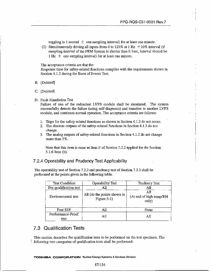
FPG-RQS-C51 -0001 Rev.7
toggling is 1 second ±_ one sampling interval) for at least one minute.(2) Simultaneously driving all inputs from 0 to 125% at 1 H-z ± 10% interval (if
sampling interval of the PRM System is shorter than 0.1isec, interval should be1 Hz ±- one sampling interval) for at least one minute.
The acceptance criteria are that the:Response time for safety-related functions complies with the requirements shown inSection 4.1.2 during the Burst of Events Test.
B. [Deleted]
C. [Deleted]
D. Fault Simulation TestFailure of one of the redundant LYPS module shall be simulated. The systemsuccessfully detects the failure (using self-diagnosis) and transfers to another LVPSmodule, and continues normal operation. The acceptance criteria are follows:
1. Trips for the safety-related functions as shown in Section 4.1.2 do not occur.2. The discrete outputs of the safety-related functions in Section 4.1.2 do not
change.3. The analog outputs of safety-related functions in Section 4.1.2 do not change
more than 5 %.
Note that this item is same as Item E of Section 7.2.2 applied for the Section.5.1.6 Item (b).
7.2.4 Operability and Prudency Test Applicability
The operability test of Section 7.2.2 and prudency test of Section 7.2.3 shall be
performed at the points given in the following table.
Test Condition Operability Test Pruriency TestPre-qualification test All All
AllEnvironmental test All (At the points shown in (At end of high temp/RH
Figure 5-1) only)
Post SSE All NonePerformance-ProofAlAl
test
7.3 Qualification Tests
This section describes the qualification tests to be performed on the test specimen. The
Sfollowing two categories of qualification tests shall be performed:
TOSHIBA CORPORATION Nuclear Energy Systems & Services Division
87/ 134
FPG-RQS-C51 -0001 Rev.7
(1) Qualification TestsQualification Tests for Environmental test and post SSE test shall be performed inorder to confirm that the Test Specimen meet the requirements provided in thisERS. In addition, these tests shall be performed to operate of the Test Specimenunder the subjected stress conditions.
Qualification Tests shall be performed on the Test Specimen after successfullyperforming the pre-qualification Test,
The following tests are performed as part of the Qualification Tests:
A. System Set-up and Check-out TestThis test is performed before the each step at B through H. If the test locationis changed, this test is performed prior to any new test.
B. Environmental TestC. Seismic Test
(Resonance Search Test and tri-axial Seismic Withstand Test)D. EMI / REITestE. Surge Withstand TestF. EFT/B TestG. ESD TestH. Class 1E to Non-Class 1E Isolation Test
(2) Performance-Proof TestThis test shall be performed on the qualification tested Test System as a finaldemonstration of acceptable system performance.
The following tests are performed as part of the performance-proof tests:
A. System Set-up and Check-out TestB. Operability TestC. Prudency Test
7.3.1 Test Specimen Requirements7.3.1.1 Test Specimen Hardware Configuration and Arrangement Requirements
The hardware configuration of the Test Specimen shall conform to the PRM Systemconfiguration specified in Section 5.2.1. The Test Specimen is a part of the PRMSystem; the Test Specimen includes one LPRM./APRM Unit, one LPRM Unit, and oneFLOW unit. LPRM unit shall include 12 LPRM modules.
7.3.1.2 Test Specimen Software Requirements
TOSHIBA CORPORATION Nuclear Energy Systems & Services Division
8 8/134
FPG-RQS-C51 -0001 Rev.7
The Test Specimen shall include the FPGAs in which the application logic have beenembedded.
7.3.1.3 Test Support Equipment Requirements
The test support equipment to support test shall be provided in accordance with EPRITR-107330 Section 6.2.3.The supporting equipment included is:
* Panels or other devices for connecting to the inputs and outputs, which containsprocedures for connecting, simulating inputs and monitoring outputs.
* Test and measurement equipment shall have the accuracy needed to support the testacceptance criteria.
* Any special tools and devices needed to support testing.* All test equipments shall be controlled per IEEE 498.
In addition, the following requirements shall be met.
* Relays used in the Test Equipment that generates the simulated output signals tothe RPS shall comply with the relay requirements shown in Section 4.3.1.
* Input signal specification for relays used in the Test Equipment that generates thesimulated Output signals to the RPS shall comply with the output signalspecification for DIO module shown in Section 5.2.3.1.
7.3.2 Qualification Tests and Analysis requirements
Qualification tests shall be performed as described in the following sections.All testing shall be performed on the calibrated PRM System with setpoint valuesadjusted to nominal values.
7.3.2.1 Aging Requirements
The following tests represent the aging factors that the PRM System will be exposed toduring qualification tests:
(1) Environmental (Abnormal Temperature and Humidity)(2) Seismic(3) EMI/REI(4) Surge Withstand(5) ESD(6) EFT/B Test
The environmental test must be performed before the other tests. The order of theother five tests is pernutable.
TOSHIBA CORPORATION Nuclear Energy Systems & Services Division
89/134
FPG-RQS-C51 -0001 Rev.7
7.3.2.2 EMI/REI Test Requirements
EMJ/RFI test shall be performed to the level and for the emission types specified inSection 5.5.3.
The acceptance criteria are specified in Section 5.5.3.If the Test Specimen does not satisfy the acceptance criteria for each test in theapplication of the specified level, the reduced susceptibility tests shall be additionallyperformed.
7.3.2.3 EMI/RFI Test Mounting Requirements
Test Specimen shall be connected to ground. The grounding used for these tests shall
meet 'grounding and shielding requirements specified in Section 5.2.4.5.
7.3.2.4 Environmental Test Requirements
Environmental test shall be performed to the environmental withstand requirementsIgiven in Section 5.5.1 to assure that the PRM System does not have fail its performancedue to service conditions of temperature and humidity.Abnormal environmental test shall be performed using the proffe given in Figure 5-2with power supply that maximum dissipate heat into the PRM System.
7.3.2.4.1 Environmental Test Mounting Requirements
The Test Specimen shall be mounted in the environmental chamber on a simplestructured rack that does not enclose the chassis. The environmental air shall bemonitored at the bottom of the chassis. No additional cooling fan should be includedin the chamber.
7.3.2.5 Seismic Test Requirements
The Test Specimen shall meet its performance requirements for the seismic loadsspecified in Section 5.5.2. All seismic tests shall conform to IEEE Std 344. Tri-axial,random, multi-frequency shaking table shall be used for seismic withstand capability.
The vibration aging shall use the five OBEs with the Required Response Spectrum(RRS) as shown in Figure 5-3 followed by an SSE with the RRS as shown in Figure5-3.
7.3.2.5.1 Seismic Test Mounting Requirements
The Test Specimen shall be mounted on a structure that shall be stiff enough so thatthere are no resonances below 100Hz with the Test Specimen mounted on it. Each unitshould be fixed to the shaking table.
TOSHIBA CORPORATION Nuclear Energy Systems & Services Division
90/134

FPG-RQS-C51 -0001 Rev.7
7.3.2.6 Seismic Test Measurement Requirements
The relay contact monitor shall be connected to all relay output channels in the TestSpecimen. During seismic test, the relay contacts should be capable of changing statefrom energized to de-energized and de-energized to energized. Any spurious changeof state should be not exceeding 2 milliseconds for both energized and de-energizedrelays.
In addition to the control accelerometer, one or more response accelerometer for TestSpecimen shall be mounted on each chassis (the Test Specimen consist of four chassis).The additional accelerometers shall be located to establish the maximum accelerationthat occurs in each chassis.
7.3.2.6.1 Seismic Test Performance Requirements
The following tests shall be performed in the order shown:
(1) Resonance Search(2) Five tri axial OBEs(3) A tri-axial SSE(4) Operability Test
7.3.2.6.2 Seismic Test Spectrum Analysis Requirements
In addition to reporting the test response spectrum from the control and specimenIresponse accelerometers at the damping given in Figure 5-3 (5%), the spectrum is alsoreported for 1/2, 1, 2 and 3 % damping.
7.3.2.7 Surge Withstand Capability Test Requirements
Surge withstand capability test shall be performed per the requirement of Section 5.5.4.The surge shall be applied to the points indicated in that section. For the AO moduleand the DIG module, the surge needs to be applied to representative points for a giventype of module. The test shall be conducted in accordance with IEC61000-4-5 andIEC6 1000-4-12.
7.3.2.7.1 Surge Withstand Capability Test Mounting Requirements
The Test Specimen shall be connected to ground. The grounding and shielding shallmeet requirements specified in Section 5.2.4.5.
7.3.2.8 Class 1E to Non-Class 1E Isolation Test Requirements
Class IE to Non-Class 1E isolation capability test shall be performed per requirementsspecified in Section 5.5.7. The test only needs to be applied to representative pointsfor AG modul, DIO module, and TRN modules.
TOSH-IBA CORPORATION Nuclear Energy Systems & Services Division
91/134
FPG-RQS-C51 -0001 Rev.7
7.3.2.8.1 Class 1E to Non-Class 1E Isolation Test Mounting RequirementsThe Test Specimen shall be connected to ground. The grounding and shielding shall
meet the requirements specified in Section 5.2.4.5.
7.3.2.9 EFT/B Test Requirements
EFT/B withstand capability test shall be performed per the requirements of Section5.5.5. For the AO module and the DIO module, the EFT/B test needs to be applied torepresentative points for a given type of module. The test shall be conducted inaccordance with JEC6 1000-44.
7.3 .2.10 ESD Test Requirements
ESD test shall be performed to assure that the Test Specimen does not fall due to servicecondition for the ESD level specified in Section 5.5.6. The Test Specimen shall beconnected to ground: The grounding and shielding shall meet requirements specifiedin Section 5.2.4.5.The acceptance criteria following application of the ESD are given in Section 5.5.6.
7.3.2.10.1 ESD Test Mounting Requirements
Test Specimen shall be connected to ground. The grounding and shielding shall meetthe requirements specified in Section 5.2.4.5.
7.3.2.11 Power Quality Tolerance Requirements
The power source requirements are listed in Section 5.5.8. Power Quality Tolerance testto the input voltage range given in Section 5.5.8 shall be performed (1) during thesystem validation test, (2) at the end of the elevated temperature in the environmentaltest while the Test Specimen is still at high temperature, and (3) after the Seismic test.The test shall include reducing the source to a level sufficient to test the requirement perSection 7.2.1.
Redundant power supply module shall be tested with the same AC power supplyconnected to both modules during the test.
7.3.3 Requirements for Compliance to Specifications
The Test Plan shall define the acceptance criteria of the Qualification Test conformingto the requirements in Section 6.4.4 of EPRI TR-107330.
8 Packaging and Shipping
Packaging and shipping shall be in accordance with ANSI N45.2.2 Level A.
TOSHIBA CORPORATION Nuclear Energy Systems & Services Division
92/134

FPG-RQS-C51 -0001 Rev.7
8.1 Packaging Requirements
Packing requirements shall be provided by NIC SD. Requirements shall include:
a. Items shall be packaged to avoid damage or degradation due to variousenvironmental and handling factors which may be encountered during shipping andstorage.
b. Packaging shall include desiccant materials as required.
c. Items shall be inspected for cleanliness prior to packaging. Items not immediatelypackaged shall be protected from contamination.
d. Cushioning shall be provided to protect against shock and vibration.
e. Items and containers shall be marked with appropriate identification.f. Copies of packing lists shall be included with each carton shipped.
g. ESD sensitive items shall be appropriately packaged, handled and marked.h. Packaging shall be suitable for movement using hand trucks.i. Special handling or storage requirements shall be marked on the containers.
8.2 Shipping Requirements
Shipping requirements shall be provided by NICSD. Requirements shall include use offully enclosed vehicles, special handling and stacking instructions as necessary, andcontainer markings and protective covers.
The means of transportation shall be consistent with the protection classification of theitem and with the packaging methods employed.
Transportation shall be by use of fully enclosed vehicles from reputable shipping firmsto minimize the possibility of theft and vandalism during shipment of items.
Where special care is deemed necessary to avert damage, written instructions coveringthe located and stacking limit of the crates or boxes on the transport vehicle shall bespecified; these shall be marked on the container.
Identification and marking on the outside of packages shall be maintained duringshipping.
8.3 Storage Requirements
Storage shall be in accordance with ANSI N45.2.2 Level A.IStorage requirements shall be provided for all items by the manufacturer. Requirementsfor storage shall include temperature, humidity, and any static control requirements.
TOSH-IBA CORPORATION Nuclear Energy Systems & Services Division
93/134

FPG-RQS-C51 -0001 Rev•7
9 Documentation Requirements9.1 Equipment Documentation Requirements
The following documents shall be prepared.
9.1.1 Equipment General Overview Documentation
The system documentation shall include an overview of the generally qualified thePRM System. The overview should include the Equipment Design Specification and theElectrical Cable Wiring Diagram.
The Equipment Design Specification shall include the following information:
A. Description of the equipment structureB. [Deleted]C. Installation information
1. Any variations in mounting.2. Information on torques to use for any mounting screws.3. Any requirements or limitations on the structure on which the PRM System
can be mounted on, including space and clearance requirements4. Any limitations on distance between the equipment and other components.5. Requirements and specification for any user-supplied hardware required for
mounting and connection to the PRM System.6. Any special handling restriction while installing the units and modules.7. Grounding and shielding requirements
D. Handling and storage requirementsE. A description of the self-diagnostics and redundancy features.
The Electrical Cable Wiring Diagram (ECWD) shall include information on the types ofthe interconnections to be used between units based on Figure4-1.
9.1.2 (Deleted)
9.1.3 Users Manual
The Users Manuals shall include the following information:
A. Information on the operation of the units• Significance of any status indication* Any special procedures that should be used for operation* The use of any switches or controls that are part of a module* Operation and use of any redundancy feature included in the units
B. Information on the maintenance of the modules and the unitsL* Any hardware configuration item for each module
TOSHIBA CORPORATION Nuclear Energy Systems & Services Division
94/134
FPG-RQS-C51 -0001 Rev.7
o Information for calibration* Information for troubleshooting* Information for maintenance
(Measuring and Test Equipment connection,)* Information for preventive maintenancb
(i.e. air ifilter cleanliness, terminations checks, power supply checks, andinstrument ground checks)
* [Deleted]* Trouble shooting, errors, and self-diagnostics messages
9.2 Final Documentation Requirements
All documentations supporting the qualification of the PRM System shall be provided.The requirements for documents to define and record the qualification process includeprogrammatic items to meet Sections 4 and 8 of IEEE Std 323 plus the technical itemsand acceptance criteria. The items that are to be covered in the documentation are givenin the following Subsections.
9.2.1 Programmatic Documentation.
The following items are required to document all aspects of the qualification process.
A. Master Test plan that include:
1. Pre-Qualification test plan2. Environmental qualification test plan3. Seismic qualification test plan4. Surge withstand capability qualification test plan5. Class 1E to Non-lE isolation qualification test plan6. EMI/RFI qualification test plan7. EFT/B test plan8. ESD test plan9. Test Performance proof test plan
B. Following test procedures :
1. System Set-up and Check-out test procedure2. Burn-in test procedure3. Operability Test procedure4. Prudency test procedure5. Environmental test procedure6. Seismic test procedure7. Surge withstand capability test procedure8. Class lE to Non-Class lE isolation test procedure9. EMJIRFI test procedure10. ESD test procedure
TOSHIBA CORPORATION Nuclear Energy Systems & Services Division
95/134
FPG-RQS-C51-0001 Rev.7
C. Test reportTest report shall include reports that correspond to each of the plans described initem A.
D. Report on all auditsReport on all audits shall include the findings and observations from the audits,and document the closure of any open issues resulting from the audits.
E. Reports on design evaluationsReports on design evaluations shall address requirements that cannot be reasonablyaddressed by test.
9.2.2 Technical Items
The documentation of technical items is used to establish and document the TestSpecimen, describe the environmental conditions to be tested, design life determination,and pre-aging requirement.
This ERS includes following technical items:
A. Test specimen requirementsB. Test specimen purchasing recordsC. Test specimen documentation, see Section 9.2.6, 9.2.7, 9.2.8, 9.2.9, 9.2.10D. Test document per Section 9.2.11
9.2.3 Application Guide
The Application Guide shall describe the qualification envelop in detail, and provide allof the configuration infonnation needed for guidance in applying the FPGA-based Unitsto the PRM System.
Application Guide shall include:
A. The results of the environmental operability tests shall be evaluated and theperformance measurements and other suitable information used to describe thequalification envelope for accuracy, response time, and etc. The sufficient detailinformation to permit comparing the test results to the needs of the particular safetysystem shall be described.
B. The applied seismic level from the test response spectrum where the PRM Systemmet the requirements per Section 5.5.2 shall be reported as the seismic withstandcapability. The seismic withstand capability shall be reported for all damping valueused in the test data analysis. The spectrum for the Test Specimen accelerometersas well as the control accelerometers shall be included.
IC. The Class 1E to Non-Class lE isolation level used in the test shall be reported as
the qualification value for this parameter.
TOSHIBA CORPORATION Nuclear Energy Systems & Services Division
96/134

FPG-RQS-C51 -0001 Rev.7
D. The surge withstand capability level used in the test shall be reported as thequalification value for this parameter.
E. The performance of the PRM System during EMI/RET test shall be reported for alltest levels including the performance of each unit.
F. The actual variation of the PRM System performance during power supply qualitytest shall be included.
G. A complete description of the PRM System configuration and detail testconfiguration of each module shall be provided.
H. The configuration information shall include mounting, grounding, and shieldingmethods used during the tests.
I. The summary of the FMvEA and availability analysis shall be included for each unitin the qualification shall be provided.
J. Setpoint analysis support information produced per Section 5.1.3.K. Information from the surveys and audits of the manufacturer's process that are
applicable to future purchasing shall be included.L. A description of the redundancy features included in the qualification.
IM. A description of external devices applied by the qualification or needed to meetany requirement applicable to the qualified equipment.
N. A description of the configuration management0. [Deleted]P. Any special practical mounting methods that were used to meet the seismic
requirements.Q. A definition of qualification envelops for specific modules that are different from
the overall envelope.R. A description of any application hardware or software features that are assumed in
order to meet qualification requirements.
9.2.4 Supporting Analyses Documentation
A. An FMEA report that is specific to the qualified PRM shall be provided.B. An Availability/Reliability Analyses report that is specific to the PRM
configuration shall be provided.The analysis includes the basis for values used in the analysis including the use ofoperating experience (if used).
9.2.5 V&V Documentation
The following documents are needed to support the V&V process and related softwarequality processes.A. Unit and Module specificationB. FPGA specificationsC. Software V&V planD. Software V&V reportE. Users Manuals
9.2.6 Test System Description
TOSHIBA CORPORATION Nuclear Energy Systems & Services Division
97/134

FPG-RQS-C51 -0001 Rev.7
The Equipment Design Specification describes the Test Specimen hardware andsoftware shall be provided. The contents should be similar to that of the hardwaredesign description.
9.2.7 Critical Characteristics
The Preliminary Technical Evaluation Report shall include a definition of the criticalcharacteristics covered by the qualification Test Specimen and qualification testincluding pre-qualification test.
9.2.8 Test System Drawing
As part of the generic qualification, a set of documents sufficient to define the TestSpecimen shall be provided.
The document shall include:
A. Electrical Cable Wiring Diagram containing a schematic of the Test Specimen,including the external devices to create inputs of the PRM and capture outputs ofthe PRM, and Test Specimen wiring, power distribution and grounding
B. Layout of Test Specimen chassis and qualification test fixturesC. Test Specimen mounting and mounting fixtures, including special installation
requirement.
9.2.9 System Software/Hardware Configuration Document
Software and hardware configuration used for pre-qualification and qualification test
shall be documented. This includes:
A. The identification and revision of the application logicB. The serial numbers of the hardware
9.2.10 System Setup/Calibration/Checkout Procedure
All of the system setup, calibration and checkout procedures for pre-qualification and
qualification test shall be included in the qualification document.
9.2.11 System Test Documentation
The System Validation Test Plan and the Test Report shall be provided. The documentsshall include:
A. Test requirementsB. Acceptance criteria for all acceptance, and qualification test. The acceptance
criteria are developed from the system requirements, configuration, and testinstrumentation
TOSHIBA CORPORATION Nuclear Energy Systems & Services Division
98/134
FPG-RQS-C51 -0001 Rev.7
C. Sequence of testD. Vehicles for recording the test resultsE. Requirements for Test Equipment, including the required instruments list and a
performance specification for each instrument. These requirements shall conformto IEEE Std 498.
A Test Report summarize the test results.
10OAbbreviationsAI Analog InputAO Analog OutputAPRM Average Power Range MonitorBWR Boiling Water ReactorDI Discrete InputDO Discrete OutputECWD Electrical Cable Wiring DiagramEEPROM Electrically Erasable Read Only MemoryEFT/B Electrically-Fast Transient/BurstEMI • Electro-Magnetic InterferenceEPRI Electric Power Research InstituteERS Equipment Requirements SpecificationESD Electrostatic Discharge
IFE Functional ElementEMI Electromagnetic InterferenceFMEA Failure Modes and Effects AnalysisFPGA Field-Programmable Gate Arry,FS Full ScaleEMIl Human Machine InterfaceIEEE Institute of Electrical and Electronic EngineersLED Light Emitting DiodeLPRM Local Power Range MonitorLVPS Low Voltage Power SupplyMDS Material Data SheetMTTR Mean Time To RepairNED Nuclear Energy systems & services DivisionNICSD Nuclear Instrumentation & Control Systems Department, Fuchu
ComplexNIST National Institute of Standard and TechnologyNRC Nuclear Regulatory CommissionNRW-FPGA Non-Rewritable Field Programmable Gate ArrayOBE Operating Basis EarthquakePRM Power Range MonitorPRS Problem Reporting SheetPSNE Toshiba Corporation, Power Systems Company, Nuclear EnergyRCV ReceiverRFI Radio Frequency InterferenceRPS Reactor Protection System
TOSHIBA CORPORATION Nuclear Energy Systems & Services Division
99/134
,FPG-RQS-C51 -0001 Rev.7
RRSSSESILSQAPSQ-ROOT
ITRNVHDLV&V
Requirement Response SpectrumSafe Shutdown EarthquakeSoftware Integrity LevelSoftware Quality Assurance PlanSquare RootTransmitVery high speed integrated circuit Hardware Description LanguageVerification and Validation
TOSHIBA CORPORATION Nuclear Energy Systems & Services Division
100/134

FPG-RQS-C51 -0001 Rev.7
Attachment A-i1Compliance and Traceability Matrix of Chapter 4 with IEEE Std 603-1991
TOSHIBA CORPORATION Nuclear Energy Systems & Services Division
101/134

FPG-ROS-C51 -0001 Rev.7 Attachment A-I
Attachment A-I: Compliance and Traceability Matrix of Chapter 4 with IEEE Std 603-1991
SECTION [ IEEE Std 603-1991 REQUIREMENTS I ERS Chapter 4 1COMPLIANCE COMMENTS
1 Scn. Description of IEEE scope. --- No requirements.2 Dlefinitions. List of definitions used in the IEEE. -- -- No requirements.
Reeec. List of documents referenced in the -- -- No requirements.3 IEEE.4 Safet system desimiation. - Section heading)
A specific basis shall be established for the designof each safety system of the nuclear powergenerating station. The design basis shall also beavailable as needed to facilitate the determinationof the adequacy of the safety system, includingdesign changes. The design basis shall beconsistent with the requirements of ANSI/ANS51 .1-1983 or ANSI/ANS 52.1-1983 and shalldocument as a minimum:
4.1 Safety systemn desienation. 4.1.1 Design Basis Event ComplyThe design basis events applicable to each modeof operation of the generating station along withthe initial condition and allowable limits of plantconditions for each such event.
4.2 Safety system designation. ;4.1.2 Safety- Related Functions ComplyThe safety functions and corresponding protectiveactions of the execute features for each designbasis event.
4.3 Safety system designation. 4.4.2. Operating Bypass ComplyThe permissive conditions for each operatingbypass capability that is to be provided.
4.4 Safety system declaration. 4.1.2 Safety-Related Functions 'ComplyThe variables or combinations of variables, or 4.2 Summary System Descriptionboth, that are to be monitored to manually orautomatically, or both, control each protectiveaction; the analytical limit associated with eachvariable. the ranges (normal, abnormal, andaccident conditions); and the rates of change ofthese variables to be accommodated until propercompletion of the protective action is ensured.
4.5 Safet systemn desienation. N/A The PRM system does notThe following minimum criteria for each action contain any safety actionidentified in 4.2 whose operation may be by manual means.controlled by controlled by manual means initallyor subsequently to initiation. See IEEE Std 494-1974 CR1990).
4.8 Safet system desienation. 4.3.1 System Equipment,. ComplyF-or those variables in 4.4 that have a spatial Arrangement and Locationdependence (that is, where the variable varies asa function of position in a particular region), theminimum number and locations of sensorsrequired for protective purposes.
4.7 Safet system designation. 4.3.4 Environmental Consideration ComplyThe range of transient and steady•-statecondirtions of both motive and conrrbol power andthe environment (for example, voltage, frequency.radiation, temperature, humidity, pressure, andvibration) during normal, abnormal, and accidentcircumstances throughout wh~ich the safetysystem shall perform.
4.8 Safety system designation. N/A Those events may dependThe conditions having the potential for functional ori the plant in which thedegradation of safety system performance and for PRM system will bewhich provisions shall be incorporated to retain installed.The capability for performing the safety functions(for example, missiles, pipe breaks, fires, loss ofventilation, spurious operation of fire suppressionsystems, operator error, failure in non-safety-related systems).
4.9 Safety system desig=nation. 4.3.2. Safety Features 12 Comply Section 5.1.7 adressesThe methods to be used to determine that the hardware reliability goal.reliability of the safety system design is And the method isappropriate for each safety system design and described in EPRI TR-any qualitative or quantitative reliability goals that 107330. Section 5.1.7 ismay be imposed on the system design. confirmed to comply with
EPRI TR-107330 inAttachment B.
102/1 34
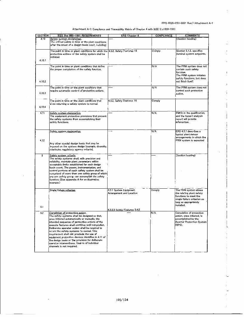
FPG-ROS-C51-O0001 Rev.7 Attachment A-i
Attachment A-i: Compliance and Traceability Matrix of Chapter 4 with IEEE Std 603-1 991
SECTION IEEE Std 803-1991 REQUIREMENTS ERS Chaoter 4 COMPLUANCE COMMENTS4.10 Safety system designation. -- (Section heading)
The critical points in time or the plant conditions,after the onset of a design basis event. including:
The point in time or plant conditions far which the 4.3.2. Safety Features 15 Comply Section 5.1.3. specifesprotective actions of the safety system shall be nominal system setpoints.initiated.
4.10.1
The point in time or plant conditions that define -N/A The PRM system does notthe proper completion of the safety fimotion, contain such safety
function.The PPM system initiatessafety functions, but does
4.10.2 not finish itself.
The point in time or the plant conditioos that -N/A The PPM system does notrequire automatic control of protective actions. control such protective
4.10.3 action.
The point in time or the plant conditions that 4.3.2- Safety Features 16 Complyallow returning a safety system to normal.
4.10.4
4.11 Safety system designation. N/A FMEA in the qualification,
The equipment protective provisions that prevent and the hazard analysisthe safety systems from accomplishing their report will providesafety functions. infomartion.
Safety system designation. N/A ERS 4.3.1 describes atypical plant sensorlarrangements in which the
4.12 PRM system is expectedAny other special design basis that may beimposed on the system design (example, diversity,interlocks, regulatory agency criteria).
S Safety system criteria. -(Section heading)The safety systems shalL with precision andreliability, maintain plant parameters withinacceptable limits established for each designbasin event_ The power, instrumenrtation, andcontrol portions of each safety system shall becomprised of more than one safety group of whichany one safety group can accomplish the safetyfunction. (See appendix A for an illustrativeexample.)
Single-failure criterion. '4.3.1 System Equipment, Comply The PPM system allowsArrangement and Location the relating plant safety
functions to meet thesingle-fai'lure criterion aslong as appropriately
5.1 installed.
4.3,2-5 Safety Features 3,4,55.2 Completion of orotective action. -- N/A Completion of protective
The safety systems shall be designed so that, action, once initiated, isonce initiated automatically or manually, the accomplished by theintended sequence of protective actions of the Reactor Protection Systemexecute features shall continue until completion. (RPS).Deliberate operator action shall be required toreturn the safety systems to normal. Thisrequirement shall nbt preclude the use ofequipment protective devices identified in 4.11 ofthe design basis or the provision for deliberateSoperator interventions. Seal-in of individualchannels is not required.
1-
103/1 34
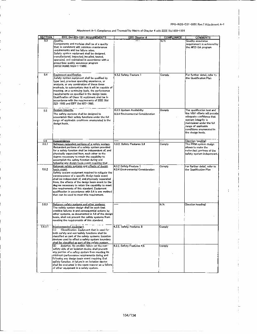
FPG-RCS-C5i-0001 Rev.7 Attachment A-i
Attachment A-i: Compliance and Traceability Matrix of Chapter 4 with IEEE Std 603-1991
SECTION IEEE Std 803-1991 REQUIREMENTS ERS Chapter 4 CCMPLJANCE COMMENTS5.3 Qualit. -- N/A Quality assurance
Components and modules shall be of a quality requirement is achieved bythat is consistent with minimum maintenance the NED GA programrequirements and low failure rates.Safety system equipment shall be designed,manufactured, inspected, installed, tested,operated, and maintained in accordance with aprescribed Quality asserance program(ANSI/ASME NQA-I-l1989).
5.4 Equioment cualification. 4.3.2 Safety Feature 1 'Comply. For further detail, refer toSafety system equipment shall be qualified by the Qualification Plantype test, previous operating experience, oranalysis, or any combination of these threemethods, to substantiate that it will be capable ofmeeting, on a continuing basis, the performancerequirements as specified in the design basis.Qualification of Class 1 E equipment shall be inaccordance with the requirements of IEEE Std323-1983 and IEEE Std 627-1980.
5. System inteeLit. 4.3.3 System Availability Comply The qualification test andThe safety systems shall be designed to 4.3.4 Environmental Consideration the V&V efforts will provideaccomplish Their safety functions under the full . adequate confidence thatrange of applicable conditions enumerated in The system integrity isdesign basis, maintained under the full
range of applicableconditions enumerated inthe design basis.
5.6 Tndeoendence. --- ~ Section heading)
5.6.1 9etween redundant oortions of a safety system. 4.3.2. Safety Features 3,4 Comply The PRM system designRedundant portions of a safety system provided allows to make Thefor a safety function shall be independent of, and redundant portions of thephysically separated from, each other to the safety system independent.degree necessary to retain the capability toaccomplish the safety function during and
______following; any desig~n basis event requiring that'Between safety systems and effects of design 4.3.2 Safety Feature 1 Comply For further detail, refer to
5.6.2 basis event 4.3.4 Environmental Consideration the Qualification PlanSafety system equipment required to mitigate theconsequences of a specific design basis eventshall be independent nf, and physically separatedfrom, the effects of the design basin event to thedegree necessary to retain the capability to meetthe requirements of this standard. Equipmentqualification in accordance with 5.4 is one methodthat can be used to meet this reqairement.
5.6.3 Between safety systems and other systems. -N/A CSection heading)The safety system design shall be such thatcredible failures in and consequential actions byother systems, as documented in 4.8 of the designbasis, shall not prevent the safety systems frommeeting the requirements of this standard.
5.6.3.1 Interconnected equipment,(1 ) Classification. Equipment that is used forboth safety and non-safety functions shall beclassified as part: oF the safety systems. Isolationdevices used to effect a safety system boundaryshall be classified as part of the safety system.
4.3.2. Safety Featares 8 3omply
)2) Isoiat'oo. Na credible failure on The non-safety side of an isolation device shall preventany portion of a safety system from meeting itsnminimum performance requirements during andFollowing any design basis event requiring Thatsafety function. A failure in an isolation deviceshall be evaluated in the same manner as a failureof other equipment in a safety system.
4.3.2. Safety Features 4,8 Comply
104/1 34

FPG-ROS-C51-C00Q1 Rev.7 Attachment A-i
Attachment A-I: Compliance and Traceability Matrix of Chapter 4 with IEEE Std 603-1991
SECTION IEEE Std 603-1991 REQUIREMENTS I ERS Chapter 4 ICOMPLIANCE COMMENTSEculoment in oroximitv. N/A Separation from other
equipment is achieved by5.6.3.2 the plant design
(1) Separation. Equipment in other systemsthat is in physical prosimity to safety systemequipment, but that is neither an associatedcircuit nor another Class 1 E circuit, shall bephysically separated from The safety bystemequipment to the degree necessary to retain thesafety systems' capability to accomplish Theirsafety functions in the event of The failure of non-safety equipment_ Physical separatien may beachieved by physical barriers or acceptableseparation distance. The separatien of Clans 1 Eequipment shall be in accordance with therequirements of IEEE Std 384-1981 [B3].
(2) Barrier. Physical barriers used to effect a -N/A Barriers are determined bysafety system boundary shall meet the The plant design.requirements of 5.3, 5.4 and 5.5 for the applicableconditions specified in 4.7 and 4.8 of The designb•asis.
5.6.3.3 -ffects of a sisele random failure. 4.3.1 System Equipment, Comply ,The PRM system allowsWhere a single random failure in a non-safety Arrangement and Lecation !the relating plant safetysystem can (1) result in a design basis event, and 4.32. Safety Features 3,4, 5 functions to meat the(2) also prevent proper action of a portion ef the single-failure criterion assafety system designed to protect against that long as appropriatelyevent, the remaining pertions of the safety installed.system shall be capable of providing the safetyfunction even when degraded by any separatesingle failure. See IEEE Std 379-1988 far theapplication of this requirement_
5.6.4 Dealdciei. 4.3.2.9 Safety Features ComplyIEEE Std 384-1981 provides detailed criteria forthe independence of Class I E equipment andcircuits.
.5.7 flaoahili for testine and calibration. 4.3.6 Self-Testing. ComplyCapability for testing and calibration of safety 4.4.3 Calibrationsystem equipment shall be provided whileretaining the capability of the safety systems toaccomplish their safety functions. The capabilityfor testing and calibration of safety systemequipment shall be provided during poweroperation and shall duplicate, as closely asp3racticable, performance of the safety function.!Testing of Class IE systems shall be inaccordance with the requirements of IEEE Std338-1987. Exceptions to testing and calibrationduring power operation are allowed where thiscapability cannot be provided without adverselyaffecting the safety or operability of thegenerating station. In this case:
(1) Appropriate justification shall be provided(for esample, demonstration that no practicaldesign exists).(2) Acceptable reliability of equipmentoperation shall be otherwise demonstrated, and(3) The capability shall be provided while theg~enerating station is shut down.
5.8 Information disolavs. --- (Section heading)
Displavs for manually controlled actions. -- N/A The PRM system does sotcontain any safety actien
5.8.1 by manual means.The display instrumentation provided for manuallycontrolled actions for which no automatic controlis provided and that are required for The safetysystems to accomplish their safety functions shallbe part of the safety systems and shall meet Therequirements of IEEE Std 497-1981. The designshall minimize The possibility of ambiguousindications that could be confusing to The
operator.
105/1 34

FPG-RQS-O5l -0001 Rev.7 Attachment A-I
Attachment A-i: Compliance and Traceability Matrix of Chapter 4 with IEEE Std 603-1991
SECTION IEEE Std 603-1991 REQUIREMENTS j ERS Chapter 4 COMPLIANCE COMMENTS5.8.2 System status Indication. 4.4.4 Unit and Detector Bypass Compy
:Display instrumentation shall provide accurate, 4.5.5 Main Control Roomcomplete, and timely information pertinent to 4.5.6 Annunciatorsafety system status. This information shallinclude indication and identification of protectiveactions of the sense and command features andexecute features. The design shall minimize thepossibility of ambiguous indications that could beconfusing to the operator The displayinstrumentation provided for safety system statusindication need not be part of the safety systems.
5.8.3 Indication of bypasses. 4.4.4 Unit and Detector Bypass ComplyIf the protective actions of some part of a safety 4.5.5 Main Control Roomsystem have been bypassed or deliberately 4.5.6 Annunciatorrendered inoperative for any purpose other thanan operating bypass, continued indication of thisfact for each affected safety group shall beprovided in the control room.
5.8.4 Location. 4.4.4 Unit and Detector Bypass ComplyInformation displays shall be located accessible to 4.5.5 Main Control Roomthe operator. Information displays provided formanually controlled protective actions shall bevisible from the location of the controls used toaffect the actions.
5.9 Control of access. N/A The administrative controlThe design shall permit the administrative control of access is depending onof access to safety system equipment. These plant designadministrative conrrbols shall be supported byprovisions within the safety systems, by provisionin the generating station design, or by acombination thereof.
5.10 Renair. 4.3.5 Maintenance Provisions ComplyT'he safety systems shall be designed to facilitatetimely recognition, location, replacement, repair,and adjustment of malfunctioning equipment.
Identification. N/A Identification will be metdepending on plant design
5.11 and installation.Inorder to provide assurance that therequirements given in this standard can be appliedduring the design, construction, maintenance, andoperation of the plant, indetifcation requirements
5.12 A~usiliary features. 4.32 Safety Features 17 Comply
Multi-unit stations. -- N/A The PRM is not sharedbetween units at multi-unit
5.13 generating stations.T-he sharing of structures, systems, andcomponents between units at multi-unitgenerating stations is permissible provided thatthe ability to simultaneously perform required;safety functions in all units is not impaired.,Guidance on thie sharing of electrical power:systems between units is contained in IEEE Std308-1 980: Guidance on the application of thesingle failure criterion to shared systems iscontained in IEEE Std 379-1988.
5.14 Human factors considerations. N/A ,Because the PRM Units areHuman factors shall be considered at the initial commercial grade:stages and throughout the design prbcess to e=quipment, the humanassure that the functions allocated in whole or in factors were qualified bypart to the human operator(s) and maintainer(s) ;cofirming the compliancecan be successfully accomplished to meet the =with EPRI TR-107330 insafety system design goals, in accordance with :Attachment B.IEEE Std 1023-1988.
I-
106/1 34

FPG-RQS-051-0001 Rev.7 Attachment A-I
Attachment A-I: Compliance and Traceability Matrix of Chapter 4 with IEEE Std 603-1991
SECTION IEEE Std 603-1991 REQUIREMENTS ERS Chapter 4 COMPLIANCE COMMENTS5.15 Reiblt. 4.3.2. Safety feature 12 Comply
For those systems for which either quantitative orqualitative reliability goals have been established,appropriate analysis of the design shall beperformed in order to confirm that such goalshave been achieved. IEEE Std 352-1987 and IEEEStd 577-1976 provide guidance for reliabilityanalysis.
Sense and command features-fbunctional and -- (Section heading)6 desien recuirements.
In addition so the functional and designrequirements in Section 5, The followingrequirements shall apply to the sense andcommand features:
6.1' Automatic control. 4.1.2 Safety- Related Functions ComplyMteans shall be provided to automatically initate 4.5.2 Reactor Protection Systemand control all protective actions except as (RPS)ustified in 4.5. The safety system design shall be
such that the operator is not required to take anyaction prior to the time and plant conditionsspecified in 4.5 following the onset of each designbasis event- At the option of the safety systemdesigner, means may be provided to automaticallyinitiate and control those protective actions of4.5.
6.2 Manual controL. --- (Section heading)Means shall be provided in The control room to -- N/A The PRM system does notimplement manual initiation at the division level of contain any safety actionthe automatically initiated protective actions. The by manual means.means provided shall minimize the number ofdiscrete operator manipulations and shall dependon the operation of a minimum of equipmentconsistent with the constraints of 5.6.1.
6.2.1Means shall be provided in the control room to -N/A The PRM system does notimplement manual initiation and control of the contain any safety actionprotective actions identified in 4.5 that have not by manual means.been selected for automatic control under 6.1.The displays provided for these actions shall meetthe requirements of 5.8.1.
6.2.2 ________________ __________ __
Means shall be provided to implement the manual 4.3.2. Safety Features Comply For the PRM system.actions necessary to maintain safe conditions reset'ting is the only manualafter the protective actions are completed as action that should be takenspecified in 4.1. The information provided to The after the protective actionsoperators, the actions required of these are completed.operators, and the quantity and location-ofassociated displays and controls shall beappropriate for the time period within which theactions shall be accomplished and the number ofavailable qualified operators. Such displays andcontrols shall be located in areas that areaccessible, located in an environment soitable forthe operator, and suitably arranged for operator
6.2.3 surveillance and action.
107/1 34
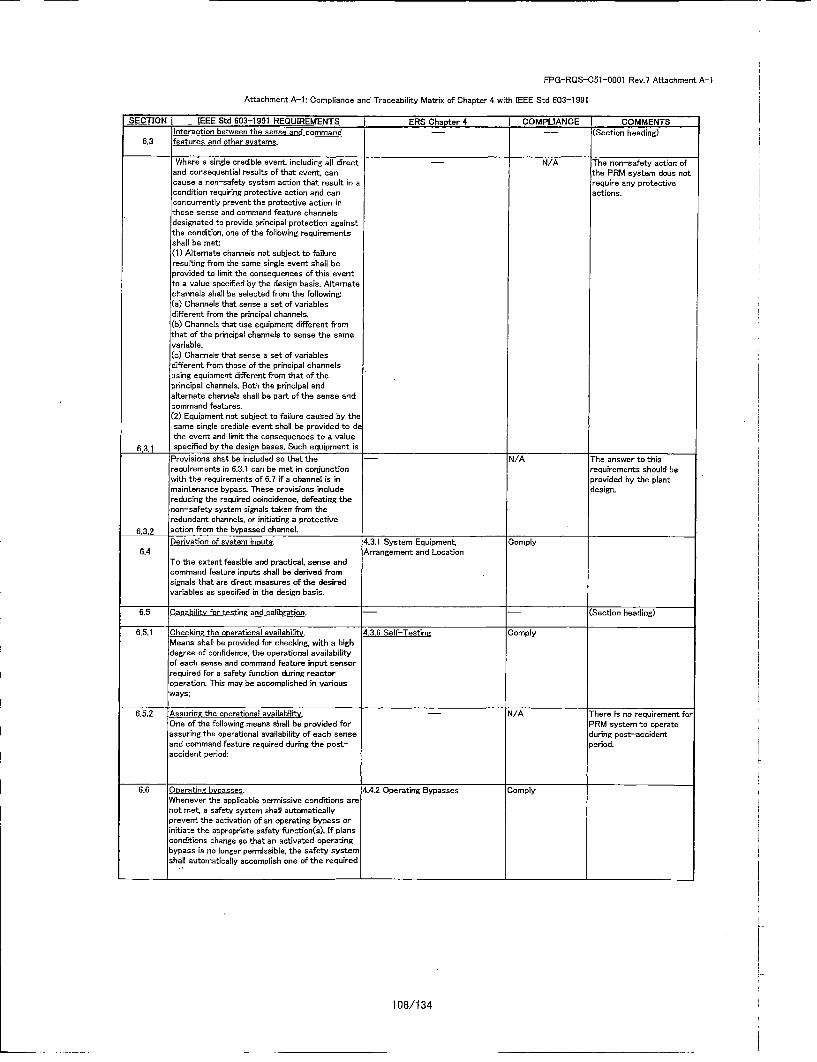
FPG-RCS-CSi -0001 Rev.? Attachment A-i
Attachment A-i: Compliance and Traceability Metrle of Chapter 4 with IEEE Std 603-1991
SECTION [ IEEE Std 803-1991 REQUIREMENTS I ERS Chapter 4 I COMPLIANCE COMMENTSInteraction between the sense and command -- -- (Section heading)
6.3 features and other systems.
Where a single credible event, including all direct -N/A The non-safety action ofand consequential results of that event, can The PRM system dous notcause a non-safety system action that result in a require soy protectivecondition reqairing protective action and can actions.concurrently prevent The protective action inThese sense and commend feature channelsdesignated to provide principal protection againstThe condition, one of The following requirementsshall be met(1) Aiternate channels net subject to failureresuiting from the same single event shall beprovided to limit The consequences of this eventto a value specified by the design basis. Alternatechannels shall be selected from The following:.(a) Channels that sense a set of variablesdifferent from The principal channels.(b) Channels that use equipment different fromthat of The principal channels to sense the samevariable.Cc) Channels that sense a set of variablesdifferent from those of The principal channelsusing equipment different from that of Theprincipal channels. Both The principal andalternate channels shall be part of The sense andcommand features.(2) Equipment not subjiect to failure caused by Thesame single credible event shall be provided to deThe event and limit The consequences to a value
6.3.1 specified by The design bases. Such equipment isProvisions shall be included so that the -N/A The answer to thisrequirements in 6.3.1 can be met in conjunction requirements should bewith the requirements of 6.? if a channel is in provided by The plantmaintenance bypass. These provisions include design.reducing The required coincidence, defeating thenon-safety system signals taken from Theredundant channels, or inititing a protective
6.3.2 action from The bypassed channel.
Derivation of system inosts. 4.3.1 System Equipment, Comply6.4 Arrangement and Location
To The extent feasible and practical, sense andcommand feature inputs shall be derived fromsignals that are direct measures of The desiredvariables as specified in The design basis.
6.5 fiapabilitv for testine and calibration. -- - (Section heading)
6.5.1 Checkine the operational availability. 4.3.6 Self-Testine ComplyMleans shall be provided for checking, with a high
:degree of confidence, the operational availabilityof each sense and command feature input sensorrequired for a safety function during reactoroperation. This may be accomplished in various
ways:
6.5.2 Assuring The operational availability. N/A There is no requirement forOne of The following means shall be provided for PRM system to operateassuning The operational availability of each sense during post-accidentand command feature required during the post- period.accident period:
6.6 COeratine bveasses. 4.4.2 Operating Bypasses ComplyWhenever the applicable permissive conditions orenot met a safety system shall automaticallyprevent The activation of an operating bypass orinitiate the appropriate safety function(s). If plansconditions change so that an activated operatingbypass is no longer permissible, the safety systemshall automatically accomplish one of The required
108/1 34

FPG-RQS-C51-O001 Rev.7 Attachment A-i
Attachment A-i: Compliance and Traceability Matrix of Chapter 4 with IEEE Std 603-1991
SECTION" IEEE Std 603-1991 REQUIREMENTS ERS Chapter 4 COMPLIANCE COMMENTS.7 Maintenance bvoass. 4.3.1 System Equipment Comely
Capability of a safety system to accomplish its Arrangement and Locationsafety function shall be retained while sense and 4.3.3 System Availabilitycommand features equipment is in maintenance 4.4.1 Operationbypass. During such operation, the sense and 4.4.4 Unit and Detector Bypasscommand features shall continue to meet therequirements of 5.1 and 5.3.
EXCEPTION: One-out-of-two portions of thesense and command features are not required to
•" meet 5.1 and 6.3 when one portion is renderedinoperable, provided that acceptable reliability ofequipment operation is otherwise demonstrated(tchat is, that the period allowed for removal from
service for maintenance bypass is sufficientlyshort to have no significanrtly detrimental effecton overall sense and command featuresavailability).
6.8 Setnonts.- (Section heading)
6.8.1 The allowance for uncertainties between the 4.3.2 Safety Features 11 Comply Section 4.3.2 states theprocess analytical limit documented in Section 4.4 expectation to utilitiesand the device setpoint shall be determined usinga documented methodology. Refer to ISA $67.04-1987
6.8.2 WVhere it is necessary to provide multiple N/A The multiple setpoints aresetyolots for adequate protection for a particular not applicable for the PRMmnode of operation or set of operating conditions, Units.!the design shall provide positive means of
ensuning that the more restrictive setpooint is usedwhen required. The devices used to preventimproper use of less restrictive setpoints shall beDart of the sense and command features.Executive f~eatures-functional and design N/A The PRM does not contain
7 requirements, execute features.In addition to the functional and designrequirements in Section 5. the followingrequirements shall apply to the execute features.
Tlhe design of= power source0
ower source requirements. NI/A is not included in PRM
design specification.
109/1 34
FPG-RQS-051 -0001 Rev.7
Attachment A-2
Compliance and Traceability Matrix of Chapter 4 with IEEE Std 7-4.3.2-1993
TOSHIBA CORPORATION Nuclear Energy Systems & Services Division
110/134

FPO-RQS-C51-0001 Rev.7 Attachment A-2
Attachment A-2: Compliance and Traceability Matrix of Chapter 4 with IEEE Std 7-4.3.2-1993
IEEE Std 7-4.3.2-1 993 ERS Chapter 4 JCOMPLIANCE COMMENTS1 Scone -- -- No requirements.2 Reference -- -- No requirements.3 Definitions and -- -- No requirements.abbreviatiorns
4. Safty System design the range of transient and steady state conditions 4.3.4 Environmental Complybasics shall include the electromagnetic environment. Consideration
includeing electrostatic discharge
51 Safety system criteria -- -- No requirements.5.1 Single Failure -- -- No requirements.IEEE Std 603 19915.2 Completion of --- No requirements.prooteotive action
iEEE Std 603 19915.3 Quality --- The requirements are
described in followingsubsections.
5.3.1 Software 4.3.2 Safety Featares 13 Comply SOAP is established for theIlevelopment requirements.15.3.2 Qualifoation of 4.3.2 Safety Features 13 Comply SOAP is established for theexisting commnercial requirements
csomuters5.3.3 Software tools 4.3.2 Safety Features 13 Comply SOAP and VVP are
established for ther~equirements
5.3.4 Verification and 4.32 Safety Features 13 Comply VWP is establised for thevalidation (V&V) requirements
5.3.5 Software 4.3.2 Safety Features 13 Comply SOAP includes the softwareconfiguration Managemenrt configuration management
5.4 Equipment qualification mEquipment qualification testing shall be performed -- N/A Executing equipmentwith the computer functioning with software and Qualification testing isdiagnostics described in Qualificationthat are representative of: those used in actual . Planoperation. All portions of the computer necessary taaccomplish the safety function, or those portionswhose operation or failure could impair the safety
function, shall be exercised during testing.
5.5 System integrity -- The requirements aredescribed in the following
subsections.
15.5.1 Design f~or computer the computer shall be designed ta perform its safety 4.3.4 Evironmental Consideration Comply
lintegrity function when subjected to all conditions, external or 4.3.5 Self-Testinginternal, that have significant potential for defeating 4.4.1 Operationthe safety function [e.g., input and output: processing 4.4.3 Calibration
failures, precision or roundoff problems, improperrecovery actions, electrical input, voltage and
frequency fluctuations, maximum credible number of:coincident signal changes, electromagnetic
interference (EM]), and others].
Ifthe design basis identifies a safety system 4.32 Safety Featares 14 Comply
preferred failure mode, failures of: the computer shallnot preciude the safety system from being placed inthat mode. Perfonoanoe of the computer restart
operations shailnot result in the safety system beinginhibited from perfonsing its function
5.5.2 Design for tent and The tent and calibration function shafi not adversely 4.4.3 Calibration Complycalibration affect the ability of: the computer to perform its
safety function. Appropriate bypass of one redundantchannel is not. considered an adverse effect in T.hiscontext_ It shall be verified that the tent andcalibration function does not affect any computerfunction not included in a calibratesn change (e.g.,
setpoint change).
V&V, configuration management, and OA ore not -N/A IThe calculation sf: ical" isrequired when the tent and calibration function, executed by the processresident en a separate computer, does nut provide computer. But the functi:onthe sole verifcation of: test and calibration data for of: the process computer isthe computer that is part of: the safety system, out: of scope of: this project
5.6 Independence Data communication between safety channels or 4.3.2. Safety Features 13 Comply
between safety and nonsaf~ety -systems shall nutinhibit the performance of: the safety function
Safety and nonsaf~ety portions of: computer softwareof: firmware may be difficult to separate.
5.7 Capability for testing --- No requirements.and calibration
IEEE Std 603 19515.8 Information displays -- -- No requirements.IEEE Std 603 1991 ___________5.5 Control of access -- -- No requirements.IEEE Std 603 1951 _____________________________________________
111/1 34
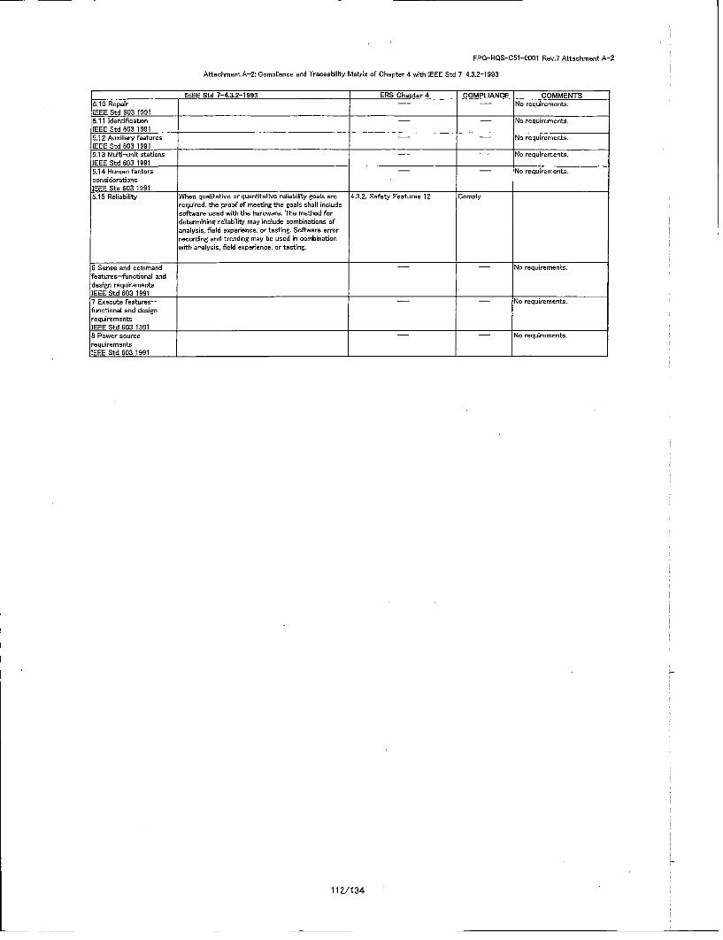
FPG-RQS-C51-0001 Rev.7 Attachment A-2
Attachment A-2: Compliance and Traceability Matrix of Chapter 4 with IEEE Std 7-4.3.2-1993
IEEE Std 7-4.3.2-1993 ERS Chapter 4 COMPLIANCE COMMENTS5.10 Repair -- -- No requirements.IEEE Std 603 19915.11 Identification -- -- No requirements.IEEE Std 603 19915.12 Auxiliary features -- -- No requirements.IEEE Std 603 1991 __________________
5.13 Multi-unit stations -- -- No requirements.TEEE Std 603 1991 ____________
5.14 Human f~acoers -- -- No requirements.considerationsIEEE Std 603 1991 __________________________5.15 Reliability When qualitative or quantitative reliability goals are 4.3.2. Safety Features 12 Comply
required, the proof of meeting the goals shall includesoftware used with the hardware. The method fordetennining reliability may include combinations ofanalysis, field experience, or testing. Software errorrecording and trending may be used in nombinationwihanalysis, field experience, or testing.
i6Sense and command -'-No raquirements.'featuras--functional anddesign requirementsIEEE Std 603 1961 ______________________7 Execute featuras-- -- -- No requirements.functional and designrequirementsIEEE Std 603 19916 Power source -- -- No requirements.requirementsIEEE Std 603 1991
112/134
FPG-RQS-C51 -0001 Rev.7
Attachment BCompliance and Traceability Matrix of Units Level requirements with EPRI TR-107330
and System Level Requirements.
TOSHIBA CORPORATION Nuclear Energy Systems & Services Division
113/134
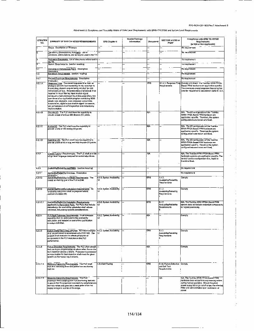
FPG-ROS-C5l-OO001Rnv.7 AttachmentSB
Attachment B: Compliance and Tracokility Matrio of Units Level Requirements with EPRI-TR107330 and System Level Requirements
Vender Package Compliance with EPRI TR-1007330IT•t SUMMARY OF EPRI TR-107330 REQUIREMENTS PRO Chapter 4 onformnutien Decament PETOAP (orENSAnn NotApplicable
1 Scope. Dnccrlption at TN Sope. --- - No requirement
3 letnitcs Ahhreviations. Acmn sr. Uist ao-f --- ,--- No requirementdefinitions, abbreviations. and acronyms used in the TR.
3 Neelemnce Documents. Ust cl docruments referenced In -- --- -- No reqoirement____thaeTRp
4 nm P oimreents. (nosesto heading) -- - - No rnqourerment
4.1 Overview of Pertoneranc Basis. Desctiptine ... - ..- No requirementintomtatiohn
4.2 Poectioval PRnuirments. (section heading) -...... .. No requirement
4.2.1 Ilenera Functional Pevrwements. Dencdptlve ...... -.. Na requirementhtnformton.
4.21.A PeoneTm. The overall responseltime tram no• -- -- PRO t.1.3.1.Response Tim oempty wlthlwnentmTe ToshiauNRW-FPPGA-enelog or discrete input exceeding Its tdp condition to Requirements Ba~sed PPM har'dwa re arc applIcation specific.hilecrsutngdisoress. Poutputws benga shall icldbie f 0 w aithSemeuirmoents described tine Romp.1.3.1thie redsutn dor t loutReputsbein set shall bnlue 100e •the mrecumroveratl responsed time comlis.1required for Input tilterng, input module signalIconversion, wale processor input data acquisition, twon
tcn imes oflan application program contanivng 3500)simple logic elements, male procesor output dataoutuaisnsilon, digital output modale signal convemsion!and parfoocance at soelf-ngnestica and redndancdyc
'implemenrtaf~n.
4.2.1.8 Dict I. The PLC shall have the capebilityto --- N/A N i/A. The I/C configuration of tire Toshiba.provide a tendl of ut least 400 discrete I/O points. NPW-FPSA-Rased PPM hardware are
application specific. Therelore, Ste systemconiq drations are known cnd fexed.
42,1 .C Anlo o_. 0. The PLC shall have lire capabilty to -- N/A -N/A. The I/C ronaiguralian al te Testribeprovide a total at 100 ea~laog I/O paints. NRW-FPPA-Based PPM hadrdware are
apptication opnvitlc. Therefore the systemconfigurations are known and toxed.
4?.1.0. Cobie liD Te PLCshail haveftht capability to --- N/A -N/A. The lIOrontitioraticoof ltheTeshitraprenide a, tended O00 analog and 400 discrete i/C points. NRW-FPPA- Based PPM hardware are
application specific, Therefore the systemnconfigurations are memow and toxed.
4.2.22 Control Ponchios Retuiremensts. The PLC shall proc/ido - - N/A - N/A. The Toshiba NPW-FPGA-Besed PPMa hrigirlsvel language designed for control altorilthms, hardware systems ace application specific. The
contnul function ocigaration (ILe., logic) Istiheretome fieet
4.2.3 Avaiuhibitei ehisifit and PFMPA. (section heading) -- -- -- No requirement
4.2231 AvtahilitifeiahhLbii DOvervewe. Destriptise .... .. - No requirementInformation.
4,.2.3.2 Avtahilbifnityeltsbiifto end Basic Recuiremeents. The 4.32. Sys'tem Anatiablipy - ERPS h.1,.7. Comnplyoverall avatiabliity goad at Ste PLC is 0.00. 12 Avn]atiatiiy/Reiiabtiity
R]eqairrerert
4.2.3.3 Antahtiitvieniahifit Cahcutation Rouahenents. An 4.32. SysrnAsotiabtilty -RSN 0.1.7. Complyovailability calculation shall be pmepored whichl 12 Anvallahifitp/Realiahilitycentfcrms to IEEE 3ti2, Requirements
,4.2.3.2.1 ,oalaoifch Pieiah~iit Caltudadain P~enanentees .3.2. Systeur Anailabnipi - ERS ,5.1.7. N/A. The Toolhia fNRW-FPSA-Bae PPMApplihable In Redundant pLns• Por PI.ts that irndado 12 ;Anailabtifiy/Relifbtiity systren does cat lotrdade redun~dant c~omponentsredundancy. the arailabitity catedahen shall edhenss Requirements far signet procesn.additifonal, redandaaoyspedlto ceeni~dwaltnw. S5
4.23.4 PLC Peuff Tlereoce Renirrmieto. PFaoltofeonmce 42.2 System1 Avaitsbtilty -N/A -- Comply.capabttipt shall be addressed einthe aemlubtitip 12calculaton, and included an part of lire quadilicationenvelope detinition.
4.23.0 Failure Sta diMEA Renudnmtents. An FtF-A analysis 4.32. Syse Aveaitbihfp ENS 0.1.7. Complyshall ke penrforted in acorndance edits IEEE 352. Tire 12 AweifabhitylRetiabilityanalyses shall evaluate tire effects at feiloem of Requirementscomponents In tire pLC modalon an the PLC5pertorroence.
42.3.6 Fallowe Dtete~to Renoirements. "irie PLC shall canoran - -N/A -Cornpip
features to pertit generating on alerm when Ste onrlicnefault detection detects a tallure. Pecesnoar-to-procem~orcommunisetion for fault deteciton shall mont Ste givenspecifiv pettrtortance requirements.
4.23.7.A Recovne Canohilit Pecarements. The PLC shall v.3.6 Sell-Testing --PRO 5.1.6. Pailare Detention Complyindiadn a wetohdog timer and power boo reoniteorig and SeoS Testfeotresw. Requirements
4.2.3.7.0 Recovery Cacahiliin Recuirements. Thre pLC - . N/A N/A. The Toohibo INRW-FPGA-based PPMprocessor shall contain power kss montitorig feetures hardware does vat perform any memory elitesto assure Sthat Ste processor suncestfully completes any durdng normal operation. Should the plantreonory writes and goes into a reset state when Ore p•ower sappy fall ortgo out cf range, Ste afqectedsupply voltage is outside ofthen range. PPM Unit will reinitiatize upon restoration at
power.
114/1 34
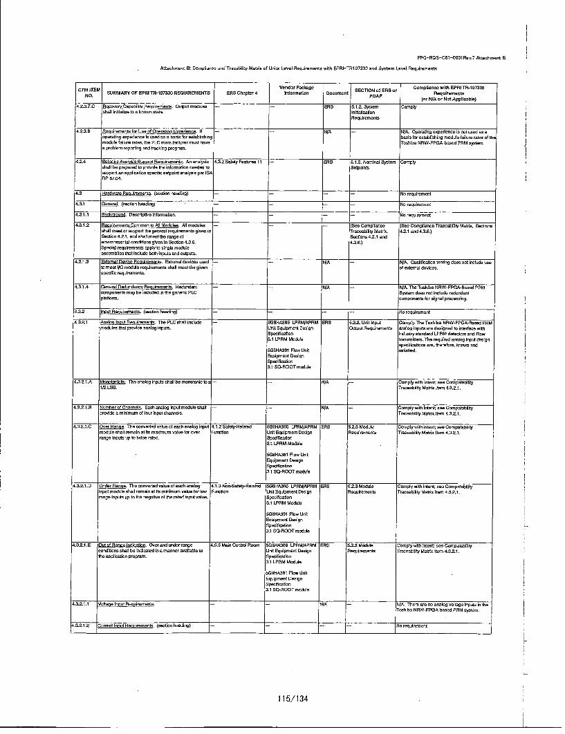
FPGI-ROS-C5t-Ot01Ren.7 Attachment. B
Attachment B: Compliance and Tracability Matrix of Units Level Requirements with EPRI-TR1 07330 and System Level Requirements
: TMo ITEM Vender Package SCINoESor Compliance with EPRI TN-1 07330N. SUMMARY OP EPR| TR-107330 REOUIREMENTS ENS Chapter 4 otheonnetion Document ECONfERorRequirements
(or N/A or Net Applicable)
4.23,7.0 Rneovery tunab~lity Rennlremento. Outpct modoles -- =RES 5.1.2- System Complyshell Inuldallae tooa known state, Inltaelizatien
RequIrements
4.S.3.E Renuirements for Use of Oeeitano Eeeetiance. It - - /A -N/A. Operaitng osperiencer is tot coed as aoperuiting eoyeritene is owed as a basis for establishing basis for estoblalloing module fallure rates of themeodole failure rates, the PLC munufacitwer most tune Tachiba NRW-FPPGA-basvd PRM systen.o problem reperting and tcacring prxgrmon.
4.2.4 Setoolot Anal nis 0/cooe Rosuirenents. An anelysis 4.3.2.Safety Peatures 11 -ENS 5.1.3. Nominal System Complyshall he prepared to preside the isicrmatuion needed to Setpointsnayport as spplicaiton epedgoi nelpoint asalysis per ISARP E7.04.
4.3 Hardware Renulrements. (section housing) -- - -- - No requiremnent
4.3.1 General. (section heading) -- - - - 0 requireoent
4.3.1.1 Eakroo. Descriptie informaiton. -- -- -- -No requirement
4.3.t1.2 flaoulrements Common to All Modolen. All modules -...... (See Camp/lance (See Compliance Traceabiity Matnic, Sect/onechalt meet or support Ste general roqcianmentc g~ven In Traceability Matrie. 4.2.1 and 4.3.E.)Section 4.2.0, cod shall meet the range of Sect/are 4.2.1 andeecimnrenental rand/tiaco given in Secotin 4.3.6. 4,3.6,)S/p~eil requirements apply to single moduleassreoblles that incded both lnpcts and outpats.
4.3.1.3 SEtemnal Danice Rancirements. External devices coed -- - NJA N/A. Qcalification tooting dean not include useto meet I/O meodale requiorenants shell meet the given of external dan/coo.opec/f/c requirements.
4.3,1.4 General Redundance Reculrmmento. Ret/sodant --- N/A -N/A. The Toshiba NRW-FPGtA-Bcsed PRMecerponents may be inoluded in the geneito PLC System does nut lox/ode reduodantplatorne ramyonents for aignal processing.
4.3.2 Iner Reccire•nrerts. (•colon beading) -- --- No reqelrement
4.3,2.1 Mnelon ner uR eoremento, The PLCanba/Iiola•de -- 5iGOHA386 LPRM/APRM :ENS 5.2.2. UnitlInput Comply. Th"e Toshiba NRW-FPGA-ttaset/PNMwe/otue 0/rot pronide analog lnpats. Unit Equipment Design Output Requirements analog inputs are designed to interface with
Specifcat/en inducstry standard LPRM defectors and Now3.1 LPRM Module transmicemr. The required analog Inpat design
opecitln•ationo are, therefore, known andSG0HA3SI Row Unit sat/c/iod.Eqcipment DesignSpecification2.1 SO-ROOT module
4.3.2.1,.A Meaorxt. The analog inputs shall be menutonic to -- -- N/A -Comply with Intent; see CormpatsblltyI/21LSB. Truceabtiity Mutix Item 4.32.1.
4,.3.2.1 .E Numbor xf Cf/annuls. Each analog inpot mdodue /ai -- -- N/A - lorply with Intent; oee Crenpatabtiitppreside a minimum of tour input channels, tracecbility Mutsic tem 4.3221.
4,321.0 , Over Ron ~e. The converted naax lue each aaelog inpct 4.1 .5 Safoty-Reaiaed 50BHA3e6 LPRM/APFRM ENS 5.2.3 Module Comply with intent; see Compatapilitymedt/oe sha/I rminen at/Bt masimant salon far oner Pucmtias Urnit Equipment Design Requitrnectnt Tracecbility Matric Item 4.32.1.range inputs op to twice rated. Specif/cation
2.1 LPRM Module
5iGuHA3el Nlow UnitEquipment DesignSpectilcetian3.1 So-ROOT met/ode
4.3.2.1.0 Under Range. The converted valuoeof eaeh analog, 4.1.3 Nen-Safetp-Relatnd 5G0/HA3S86 LPRM/APRM ENS 52?3 Module Complypwith inlxtosntasComnpatabitityinpot module shall remain ctolts re/a/mum value tar/w Pow unction Unit Equipment Design RequIrements Traxeability Matric Item 4.3.2.1range inputs op ts the negative of thre rated snpot vaube. Specif/cat/on
3.1 LPNM Met/ude
tlg8HA38l Ntow UritEquipment DesignSpeaif/cat/on2.1 SO-ROOT moducle
4.32.1.E 00000fRarmo:Lo~divait~or Oumrand otutrngerxe 4.5.5 MaelCostedReran 560HA355 I.PRM/APRIM ENS nf-3Module Uomply withmetht ctu;e Compatahbloiyc•enioSer shall be indicated inou macnn ersenuatle to Unit Equipment Design Requirements Traceability Matsx Item 4.32?1.the upplication program. Specification
3.1 LPRM Module
51GtHA361 Nlow UnitE=quipment DesignSpec/f/ca.t/on3.0 SO-ROOT moduie
43.2.1.1 V/oltue ynou Renairements. -- -- N/A - /A. Thare ore co analog voltage onputs in theToxhiba N RW-FPPSA based PRM system.
4.3.2.1.2 Current lne UReculrements. (nect/onheeding) -- --- 'go requiremoent
115/1 34

FPG-RQS-Ctt-05001Rev.? Attachment S
Attachment B: Compliance and Trocability Matrix of Units Level Requirements with EPRI-TRI 07330 and System Level Requirements
CTM ITEM Vendor Package SCONoESor Compliance with EPRI TR-157335NO. SUMMARY OF EPR! TR-107330 REQUIREMENTS ERS Chapter 4 Information Docotnent SEcTI~p 5 pf RS Requirements
(or N/A or Not Applicable)
4.3.2.1.2`A Asenal Currenttl Module Ron en. TheoPLC shelI -- 5GtHA386t LFRM/APRM ERS 5.2.3 Module Compy with intent.ThenTochibaeNRW-FPGA-include analog current inpst modules with ranges ci: 4 Unit Eqsipment Dodigy Reqoireweets •saed PRM seeing input range of 410o20 mA into 20 mA cad 10 Ito 5 mA cr 0 Is 50 mA. Speoitfiation designed ao Itetrace with indusnry Flow
3at LFRM Modide tranomittors. The Input range sf 01to3 mA indesigned to interfaece with the LPRM detectors.
5btHA381 Flew Unit The required oaineg input design specitcationsEquipment Design are. therefore, meawn and satiotied.Spesitoct/ev3.1 SO-ROOT module
4.3.2.1.2`B Anale Current Inest Module Accuracien. Overall -- it8HASB6 LPRM/APRM siRS 5.1.4. Ddntand Complymwith ivntentThenTochiba NRW-FPGA-occuraires nshell be ± 0.30% of the specliied range. Unit Equipment Design Acourocy Requirrernent itased FRM analog inpots are designed In
Syenoitaostn interlace with ihdusty' standard LFRM detnetors3.1 LPRM Module and Flow Ornsnoitnere. The required eneing
input desigy speocifictions are, therefore.uSgHA3gI Flow Unit bnown end caitisfied.Equipment DesignSyecitication3.1 SQ-ROOT module
4.3.21.2.0 Anaion CorredtnInputModure Resoruitco. Tihe minimum 4.3S2tSafeytyeatures -- ENS 5.2.3 Module Comply with inten The Tchiba NRW-FPGA-resolutnon shel he 12 bins. 11. Requiremeents gased PRM onsiog inputs ore designed Ino.
ntorrate with Industry standard LPRM detectorsand flow E~ancreittere. The required analoginput design sydesiflctone are. themafore,
known end cabtoiod.
4.3.2.1.20.t nalosComnt inoutModule CommontModeVoltaoe. -- - =S5 5.2.3 Module IN/A since the analog inputs ore not generalThe common mode voltage capability shall be at leant Rlequirements parpese cad aeo cerf-powenred,10 veins.
0.3.2`1.2.E eatne Currant moort Module Coenwos Mode Roeo..r -- -- :ES 5.2.3 Module N/A since the affront Inputs aSm not trantfooncaRoate..q. The nomione mode rejecton ratio ohall beeat Requirements to voitoge by extemai resistors, Ste'______ rat •tOS reo•frement in net onnnrefe~
4.3.21.12.F tmalon Cawnt ne out Mock/a Resrose lime. The -- -- (See Compliance (See Compliance Traceoblility Matoix itemcanere respoose tree clf cheaninog curent loyal Traceablility Moelo Item 4.2.1l.A. Response Tim e)mnodules mast soppoit the response thee requirement 4.2.1.A. ResponsegivenoinSecitonn42.1 .A. Ti3me)
'.3.2.1.2`G 'staes Current rout Module ttreuao-iwtreo asulatins. - - N/A - N/A. The Toshiba, NRW-FPPsA based FRMThe greuy-to-group isolatnon chal beeat least *:30 ccitt system analog current input wodoles (LPRMpeak Inri4 to 20 mA inputs. Module and SQ-Rest Module/ are not grouped.
4.3..2`.2`H tarles Current tout Module ClasltEto Non-iN --- N/A -N/A- The LFRM module cad the SO-ROOTlsolatfon. Thle Ceas• lE ts Non-ilE Lsolealn capability module are only aced for Cleans 1E inyuts. butshall west Sin reqloirernents 01 Section 4.6.4. riot for Non-1 E inputs.
4.3.21.2.1 mAles Current Inest Module Sawn Withsteedt Surge ---. (San Comyliance (See Crenpilen.ce Traneablitity Moult Item 4.0.2withstand shell be as gvene in Secdton 4.6.2. Traceablility Matrio Item: Sorge)
4.62? Surge)
4.3.2.1.2`J] AXeal CurrenttneattModulen cotlimnedance. Th~e -- -- ENS 52.3 Module Compli. The Toshiba. NRW-FFSA-BanedPFRMinput impedance shall be 200 ohmas macimwn. =Requirements enaing inputs owe designed In interlace withr
edasby standard LFRM detectors and Rlowt'r'e'mit tew . The reqoired aeelng Input designspesitesitora are, therefore, known and
4.32-1.3 RTfllnoutR Lesoeento. -- N/A -- N/A. Therewsno RTO loyalin theToshibaNRW-FPPA based PRM systren.
4.3.2.1. lnencacinolehut eurrements. --- N//A -N/A. Them senT/C inputin the ToshibeNRW-FPGA based PRM system.
4.3.2.2 DiscreteInput Resuiremeets. The pLC shall mhscdo 5-JgNHA3S6 LFRM/APRM ENS ir.2.3 Module Compdy withintent The design caty iholodesmodudes tht provide diraretininyts. E~achwmodule unitEquiyment Design Rleqoiremests feourinputochannses.shall pmovideew iniwmun ot B Input cbannels end Speciiatouon. The D10 module duet not include input chanonelinoiruein ldicatam that shore the ON/OFF otauLw of each 2.601 warbodle states ON/OFF indicatosw Inn each point.point Howaner. the APRMS module and FLOW
5/00NA381 FLOW unit module hrthdn ededicaiton oftan input signalEquipment Design ON/OFF status of each peed.Specfitcaion.3.20DO module
4.3.2.2`.1 Discrete ACInoat Resuirmentt. -- N/A -N/A. The Tehiba NRW-FPOA-Based PRMhadrdware danes nut Include Discrete AC Input.
4.3.2.22 Oiscrete DC Incut Resuiremnents. (sention heading) -- --- do requirement
4.3.2.22`A OscremteDC nesttModuleTones. The PLC siral -- 5ttiiHAit6 APNM/LPRM ENS 5.2.3 Module N/A. Quaelted relays will be coed to Interlace tsir~uade discrnete DO input woduies for nominal inputs ci call Design Equipment Requirements plant cysuts. San Compliance Traceability130 VDC. 24 VOC, 1it VDC and 12 hOC. Speciiatonec. Metric Item 4.0.
3.601I0 module
SGBHASS6 FLOW callDesign EqUipmentSpedifistion.3.200O module
42.2.,2.2.B Discrete DC neaut Module ON Transitbon. The input 4,5t System Interface -- ENS 5.2.3 Module N/A. OQualified relays mill be coed to ninterice towest tresiteton toON at gg VDC wan. (l2t VDC input) Requirements plant inputs. San Compliance Traceabilitycr320 VDC wan. (24 VDC input). Maloic Item 4,.0
116/1 34
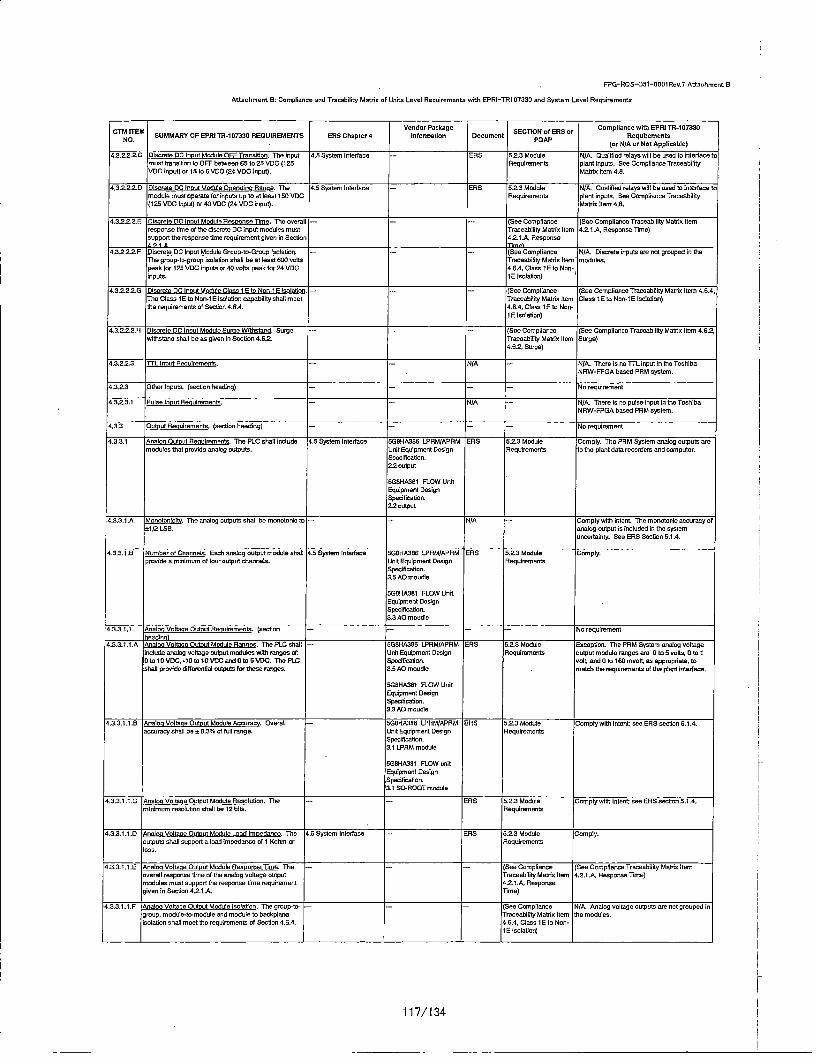
F-PG-ROS-C5t-O001lRev.7 AttachmentSB
Attachment. B: Compliance and Tracahility Matrix of: Units Level Requirements with EPRI-TR1 07330 and System Level Requirements
SCTM rsiVemiduroafg E~O fESorCopinewIth EPRI TR-i107330No.TM SUMMARY CF EPPJ TN-107330 RECUIREtMENTS ERS Chapter 4 tnformatioe Docament (oTO f R rRequAiremeAnpicale
4.3.2.2.2.C Discrete D Ineut Module OFF Transition. The input 4.0 System Interfuse -ENS 0.2.3 Module N/A. Cualifilad relays will be used to interface tmost tnonalton to OFF between 65 to SO VDC (1 25 Requlremcento plant inputs. See Compliance TreceabilityVDC input) orb1 to 6 VDC (24 VDC Input). Mtnic Itaco 4.0.
4.3.2.2.2.D1 !tscrete DO coput Module Operattno Renqe. The 4.0 System inttrfane -- ENS 0.23 Module N/A. Cualified inlays wilt beansed to interface tamodule must operete tot inputs spnto et least 1S0 VrDC Requimements plant inputs. See Cotmpianne Truceobility(125 VDC Input) cr 40 VOC (24 VDC input). Malels Item 4.0.
4.3.2.2.2.E 9iscrete DC to ut Module Resenone time. The onerait ----- (See Compliance (See Compliance Traceabiity Matein Itemrespanse itme of the disctete DC input modules must Traceability MuostoxItm 4,2.1.A, Response Thee)support toe response thee reqaitement given in Section 4.2.1 .. Response
4.3.22.2. Discnete DC Inest Module Groun-to-DGc Isolaiton. -- (See Compliance N/A. Disctete inputs aem cot grouped ita hThe group-to-groop isolation shall be at least 600 volts Traceability Manicx Item" modules.peak far 125 VDC inputs or 40 volts yeah far 2h VDC 4.6,4, Clans l tto Non-inputs. 15 Iselalioc)
4.3.2.2.2.G Dtscvate DC neatMndsaleClons iFto asI-F Iselatior,- --- See Compliance (SinCompliecce Traceability MontuxItem 4.0.4T"he Clans lo ts Non-IF isalanon capability shall meet Traceability Mai ahx tem Clans lE ts Non-IF inlutnon)the raquiretments of Section 4.6.4. 4.0.4. Clans IE ta Nis-
10E Iselation)
4.3.2.2.2.H (tincrote DC Inot Modole Same Withstood. Surge -- -- -- (Ses Compliance (See Compliance Traceability Moatrn Itom 4.6.2,withstand shall be as given in Section 4.6.2. Traceability Manzic item Samge)
4.6.2. Singe)
4.3.22.3 ntLn cotR Puirements. -- f//A ,- N/A. Theme intoTT-Linput into ToshibaNRW-FPGA besed PRM system.
4.3.2.3 Ote et. (seetion beading) --- -- -- No mequirement
4.3.2.3.1 Pulse bo ut Recuimments. -- NJA -- N/A. Theme ic ns pulse input In toe ToshibaNRW-FPGA based PRM system,
4,3,3 O Ult Resuirmments. (section heading) -- -- Na requirement
4.3.2.1 Analco OUtot Resuimments, The PLC shall include 4.5 System Inlterace 5G8OHA38S LFRM/APRM ENS 0.2.3 Module Comply. Tha PRM System analog outputs aremodules that pronide inalog outputs. Unit Equipment Design Reqoiremants Io ta plant dato recordiem and computer.
Specification,22 output
SI$8HASO1 FLOW UnitEquipment DesignSpenilication.22 output
4.3.3.1 .A Monotsnicits, The analog outputs shall beamonotonicto -- -- N/A -CmnTply Witl ntnt.t The monotoeicaccuraoy of*:1/2 ISO. analog output is Included in the system
uncertaisty. Sea ENS Section 5.1.4.
4.3.3.1 .B Number of Channels. Each analog aatput motile shall 4-.5 System Intenfaue 5Gs01A306 LPRM/APRM ENS 5.2.3 Module Comply.pravidna minhmum oftfouraoutput channels. Unit Equipment Design Reqalremoets
Specification.3.50AO mou~e
5ts0HA38l PLOW UnitEquipment DesignSpecifcation.3.3 AO macdie
4.3.3.1.1 A.naln Voltase O utt Renirmeonts. (section -- -- No rogalreToent
4.33.it.1.A PtmalnsVoltaseO utosModsle Rannes. Tha PLC shall -- 51BHA350 LPRM/APRM tiNS 52.3 Module E.ucepiton. The PRM System analog voltageicuade analog voltoge output modules with ranges of: Unit Equlpmant Design Nlequitemeets output module ranges ate 0 toO 5 vlts, oral0 to10 VDC, -i0tolO0VDCwet 0tfo05DC. ThteFPC Specificagon. voIt and 0 toi16timsolt as pproprate, tonhag provide dtitferetiat outputs fer the ranges. 3.0 AD moudle . atch toe meqalmmeeta of thoplant interface.
51G8HA381 PLOW UItt/.Equipment DesignSpenification.3.3 AD macdie
4.2.3.1.1,B ;nolsnVoltote~utoutModuieAccurac . Dverali bG8tHA300 LPRM/APNM aRS 5.2.3Module Complywithintent see ENS cenion5.1A.4accuracy shatl be * 0.3qio at foil range. Unit Eqidyment Design Nequirements
Specification.3.1 I.PRM module
5GgH140201 PLOW unitEquipment DesignSycufitcaiton.3.1 SO-ROOT module
4.3.3.1.l .C Aoaluo Volrasa Output Motile Resoludon. "The --- ENS 5.223 Module Comply with inlent, see ENS secmon 5.1.4.minimemresoiution shall be 12 hIts. Requtremmnts
4.3.3.1 .. D An• aln otssta e Meduie LisadlImeedanom, Ths 4.5 System Interface -- ENS 5.2.3 Module Comply.outputs shall sopport a. load nmopedalcue ofli Kohim or Requlirmectsloes.s
4.3.3.1.1.,E Anamnstoitase OutssModule RennornscTimo. The - - (See Compliance (See Compliance Traceabiiity Metric Itemunerall response Oweofttoecnalog voltoge output Traceabllity Metric item 4.21 A, Response Thea)modules minst support the response time reqalrement 4.2.1 .. Nesyssn.egiven in Sociton 4.2.1 .A. Time)
4,3.31.1 .F Anaal Voltate Dulct Module Isefl~oin. The group~to-- --- (See Complianme Nt/A. Analog noltoge outputs ren not grouiped ingmsup. module-to-module and module to bachplene Traceabiltity Matrix Item toe modules.isolation shall meet the requirements of Section 4.8.4. 4.6.4, Clans 10 to Non-
10 iselaition)
117/1 34

FPG-AOS-C51"-OSO0Rev.7 Attachmrent B
Attachment B: Compliance and Tracub[iity Mate/a of Un/ta Level Requirements with EPRt-TR1 07330 and System Level Requirements
CTM flM SUMMARY OF EPRI TR-107330 REQUIREMENTS ENS Veptr ndormPackage cuen SECTION of ERS or Ctptneib~~~l173NOPCete lfrtalc ocmntequirements
(or N/A or Not Applicabln)
4.3.3.1.1.6 An~f oluccleofutcut Medulo Surcetoirthsrcd. Surge- -- (See Cottplionce (See Compliance Traceability Matalo Item 4.6.3withstand nhail be an green In Senitaen 4.6.2. Traceobillty Mac/c Item Sorgn)
4.6.2, Surge)
4.33.1.2 Current C at A ulremnrnsr. -- I-- N/A -- N/A. The Toahiba NRW-FPI3A-hasod PAMI system does vat incoluda curoent coutpot
4.3.32- Dlscrete Outoul Nooairements. The PLC chatl include 4.5 Systoer Interface -- ENS 5.2-3 Module Complymoodules that provide discrete outputs. Reqairmetnets
4.3.3.2-A Numbher of Channeln. Eadh moedule shall provide o 4.5 System Ithoeacs -- ENS 5.2.3 Module Comeply.minimum of 0 output uhntolnes. Requirements
4.3.3.2.B Lehs Crot. Leohage current In the OFF stote of 4.5 Systeme Interface --- ERS 5.2.3 Module Comnply.non-nuporvised (no Intoeral itnghoch) modules shell be Reqoirementsleoo than 80¾ of the micim mas current vneded to tornON aoy digital input module.
4.3.3.2-C O utormCircuitlInterctar. Outputs must tncudena 4.5 System Interfoce - tiS n.2_.SModale touepfion. The Toshiba NRW-FPGA-busedicirocit intetroruter. Aeqoirements PRM systree dues not inclode output drcitot
interrupter.
4.3.32.D Stts ,ict Modules must iculude indcators trot - - - N/A -Excopton. fire DID module does ntt includeshoe the ON/OFF statne of eac point, output channe~l status ON/OFF indicators for
each point
4.3.3.2-1 Clscrele AC Outout Aesirenvets. -- N/A -- N/A. Theme is no discreta AC output in theToshiba NAW-FPGA booed PAM system.
4.3.3.2.2 Discrers DC Cutout Ralccrenrents. (colon heoding) --- --- No repsirement
4.3252.2.A Discrete DC Cotut Modu/n Tuces. The PLC shall '4.5 System Interface -- ENS .5,2.3 Module Comply with intent. The PAM System Output isincude discrete DC ourput modules for nominal oatputs Nequimements used ton/hp a qualitied relay thot is selected tootl12tVDC,d48VDC, 2dVDC,t15tVDCcndt12VCC. meet the specific plant apptlioano needs (e.g.,
voltage). Sen alsoe Cepospface Traceab iityMao/o Item 4.6.
4.3.3.2.2.B DiscretelC OUtout Module utouCurrent. The 4.5 System Interface -- ENS 5.2.3 Mdodle Comnplymwithl[taont Tho PAM System output isootputs most operate with an output curennt between SO Aeqoiremonta utsed toP 0h qualitied relay that is selected tomA cud 0.5 amps with an inoush capability of at isast 2 meet the spocific plant applisaiton needs (e.g..amps, current). See also Complianae Traceabtilty
lei tore"It 4,04,.3.3.2.2.0 Discrete CC Cutout Module ON State Volte Doto. 4.5 Systemo Interface -ENS 5.2.3 Modoie Comply with intent. The PAM System output is
The 0N/state voltage drop shall not osceed 2 VOC at Neqoirrements used lto nip a qoalified relay that is selected to0.5 amnps. mneet the specific plant appiloleion needs (e.g..
voltage). Sen alsoe Cornptfance Traceeblsnty4..332.22D 3omtcesDC Ostoot Module OFF Stats Leatrooe. The 4.5 System Ineroface -ENS 6.2.3 Module Comnply withnintent The PAM System output is
OFF state leahag emamoet shal oetoexceed 2mA. Nequilrementa used ta nip a qualified relay that is selected to"on t tire spec/to plant appiloaton rneds. Seer r•no Cnnltsn "r'm n+ hnlsc• Maiss Ite, 40R
s.3.32.2-.5 Discrete DC outaut Modolo Opoeratne Rnese. The 4.5 System loterfaen ENS 52.23 Moduto NI/A. Cualilted relays will be used te interface tomodule points mast operate for csoure inputs of P9t to Naquirementa plant inputs. See Compliance Traceability146 VDC rein. (125 VOC output), 35 toE60 VOC mis. (48 MoOath Item 4.8.VoCaoutput). and 2Otoa26VDC min. (S4 VDCootput).
4.3.32_2.F Discrete DC Cruat Module Nesonse Terre. The - See COmoptanne (See Coerpliance Traceability Mania Itemoserall response tim e of the Scr~•ete DC outpot Traceabiltty M aO/a Item 4.2.A. Aesponse Time)modules most sopport the resporse demo requirmenet 4.2tIA Aespanseegiven in Section 4.21.A. lime)
4.3.3.2.2.6 Discrete DC Cuou MedMul~ou lm-to-trcou isolation. 4.5 System Interface ENS 5.2.3 Module N/A. The PAM System Discrete DC outputTho group-ta-grap isolalton shall besat leant twece Nteqoimremnts module in cut grouped.nominal output.
4.3.3221H Dtiscrete DC Cutout Module Class lE to Nov-iE S - - [Sen Compliance (Seu Comnptosnce Traceability Malt/a Item 4.6A.4Isolas~on. The Class 15 to Nos-1ES isoladon oapability Traneability Man/ax Item Claus fE te Non-iE to mealon)shall erect the requirements of Secdon 4,6.4. 4.6,4, ClasscltotaNos-
tO lsisfionlc)
4.33.2-2-1 Discrote DC COtat Modute Sene Wihsotacnd. Surge • - - - ('Sen Compteanme (See Comnplincue Trameability Manic Item 4.6.3,wy'letood shralt be us given in Sectus 4.62. Traoeabn/tp Muo fsee Surge)
4.0.2-. Samge)4.3.3.2.3 Flelay CuOut Renulremento. -- -- N/A -N/A. The relays ore net in the scope of suppiy
far qualificeton or cronerercial sales.
43.3,.2.4 ITTL Cutut Neoairements. --- N/A -N/A. There in no iTL output module in troToshiba NRW-FPGA bused PAM system.
4.3A4 proessor/Other semn Cnrenenest Aeuairentents. -- - -- Ns requierement(sectaon heading)
4.3.4.1 Procemsor Loon lime Rcusirernonts. processor loop --- - See Compliance ISes Ceopliance Traceability Metric Itemlimo shall support the respocue dme requirement given Traceability Muach Item 4.2.1.A. Response lime)in Secton 4.2.1.A. 4.2-.t.A. Respocue
lime)
Alsoe, processor Ioop tree shall be fasterttsan the Enager /3.2.2 Safety Featoves - ENS 5.1.3.1. Nesponsc rme Comply.ot the analog input cunsers/an tI/mn or the peodd Requiremenvtsa ssociat ed with 2.5 trees the analog Ottier cutsoffrequency.
118/1 34

FPG-RQOS-C51i--0001Rev.? Attachment B
Att~achment B: Comptornce cod Troocaility Macrio of Unito Level Pequiremrents with EPRi-TRi107330 and System Level Reqairerenets
CT TMVendor Pockoge SECTION ofERS or Compliance with EPRI TR-i107330SN JMPVPEOT-.33B JPPANS BSCtatr efretoADcmnPeqieet
NO. POAP(or N/A or Not Appllcoible)
4.3.4.2 MemooryvCvpacityvndflatafReteniton Capability -- - ERS 0.24.,3.Mereory N/A. There iv rnoremory used to contain thePeomet. Tho momory copavity ot the main Copaitoy cod Data program in the Toshiba NPW-PPGA bacadprocessorcshail provide sufficient memory to excutae a Retention Capability PPM system.single application pevrogra with the numnber of progrorm Requiremnents,elemeots given.
The meorory osed to contain the program ohall be -- BPRS i.2.4.3.Memory N/A. There is to memory aced to contain thecapable of rtoatioig the iniotroalion fora minimumcen c6 Capacity and Data program in the Toshiba NRW-FpPGA bosedmonths with cv power applied. Retention Capability PPM system.
Peqoitemoerts.
Any memory coed for tiaid modifiable corrotanta shalt be -- ERBS ti.4.3,Memory Complycapable of at leant 100,000 write cycles. Capacity and Data
Pletentico CapabilityRertairementt.
4.3.4.3 Data Aauisition Peeuiremonls. Thre PLC shall be -ERBS 5.24.4., Transferring Compiycapable of transfeciog inlormaiton botreenr the main inlfornation betweenproceocor and I/O m odules moonted in the name or medcies and modulesospanaion chassis. The data trarrsfer roat shall supportthe response dine requirement given In Section 4.2f1.A.
4.3.4.3.A Vein Chossio Intrcannect Device Otrerution. Devices - - ERS 5.24.4,4 Transferring Complyaced ta interf ate remote or eepanmion crassis to tire inforiation betweenmain chassis shall meet the range of environmentai modules and modulescondifions titan in Sectioe 4,.26. Pailures of the is the come chassis,chaossoisnterconnect deviceo chall not debear tho ability cnltsta trocster data on the malt chassiw.
4.3A.4.B0 doltCheoass ilterocvonnet ovine FolalLr. Pa/ouem of - =RBS 502.4.4, Translerring 'Complythe chassis interoonnect devices shall cot affect informration betweenmemory capacity or malt processor data retention. modules and modales
in the sceeto cihassis,undta
4.3.4.3.C Main Chass;is itlterctnect Datvie Loss ot Power. Loan -- - RS 5.2.4.4. Tronsferring Complyol power ta chassis inremonnect devioc shalt not informnation betweendeteot the ability ta transfer dota on the mdin chtassis er modales and moduesslI/Don any other chassis, in the ~name chasosis,
anits
4.3.4.3.D Main Chrassis Intermoneect Datvce Cleans fit to Non-iE ER BS 5i.24.4. Trearserring Comply,. Non-conductlve fiber optic cableisolation. The Clove iS to Non-fE BIsolaiteon capabitity Infoermation between Inherently provides Cleans t to Nov-f Eshahl meet the weqairements ot Seotion 4,6.4. modules and modales isoliation.
in the same checcsis.anits
4.4.3.4,0 M ain Chaseis intaemovoeor Device Sunre Withstand. -- N/A - Comply. Non-ocondauitve tiber optic cabinSurge withstanod ohall be an given in Sectiton 4.6.2 inhorentiy provides cargo protection.
4.3.4.3.P aide Chassis InterconnectDevice DoateAcoaisnin 4,3.2.2Satety Features -ENS b.1,3.i. Response Time ComplyTime. Data oacquisition time thall be detenninistlo or Plequiromenttmnanutactarer shahl provide Information to establishitming effect
4.3.4,3. to edandant Inter-Proesr DecoAwouisigon Bavirpiane --- N/A -N/A. Tire Toshiba NRW-FPPA booed PPMBusses. Descriptve Iniormafirer system hardware does not need redundact
baobplure bassos.
4.34.4 flomunm aonwo Port Reoudremerrts. The mod -n N/A - Exception. Themrevae no cemmunication portsplrecessor shdll provide at least one cammaunicadon in the Toshibo NPW-PPGA bated PBM tystemo.pan.
4,3,4.5l Cocre-eswor ModoleR Buiremeett. Detodled - N/A -N/A. Them is no Coprocessor intfie Test/lbarequirements for coprocessors that may be installed in NRW-FPPA booed PPM sysrem,I/O aiota bat contain loval processing capopiuiltyindependent cf the mdin p roovovor.
4..3.4.6 Chassis Peeuirements, Chrassis mast be antale tar -5GBIAS8S PPM Uolt ERS it2.4.1. Chassis Coinpty
mounting le a standard tO inch roh and most have Equipmoest Devitn Reqidrementseadequate strength and provide poshiSve hold down ot Spedificationmodides sofcln to meei sehantawlithstand 3.2 Chassisreuiremnents.
4.3.4.7 fachup Davises/Redcodano/RPevairtements. -- -I No requirementDesoriptove information.
4.3.4.7.A Retadonct Devive Peeuiremetts. Transfer moa -- tiGBHA3a PPM Uinit --ERS 0.5.8 Power Supply Complyredundant device ohall eoar witino the larger ci the Eiquiprennt Destgnmalt processor scan cycle or three data coversiton Specilicationcycles ol the fidled module. 2.3 Unit Power Sapply
4,3.4.7.B Pedvodant Device Penuirewents. Undetected tailures I - - N/A -N/A. The tailure ot one LYPS module isiv redundant components ohdi be detestable doding indicated in STATUIS Miodule. So theme ame noperiodic surmeiliance. undetected failures in redundant comnponetsr.
4.2,4.7,C Pedattdant Devive Revoirementa. Diegrostics shall net -- - /A -N/A. The redandanth LVPS muoules popratemcciv lc Ideterminate faillow states and repetiftve parallel. So repetitive sw, itching between LVPSswitching between redandant componenis, modules does not 0OcCr.
119/1 34
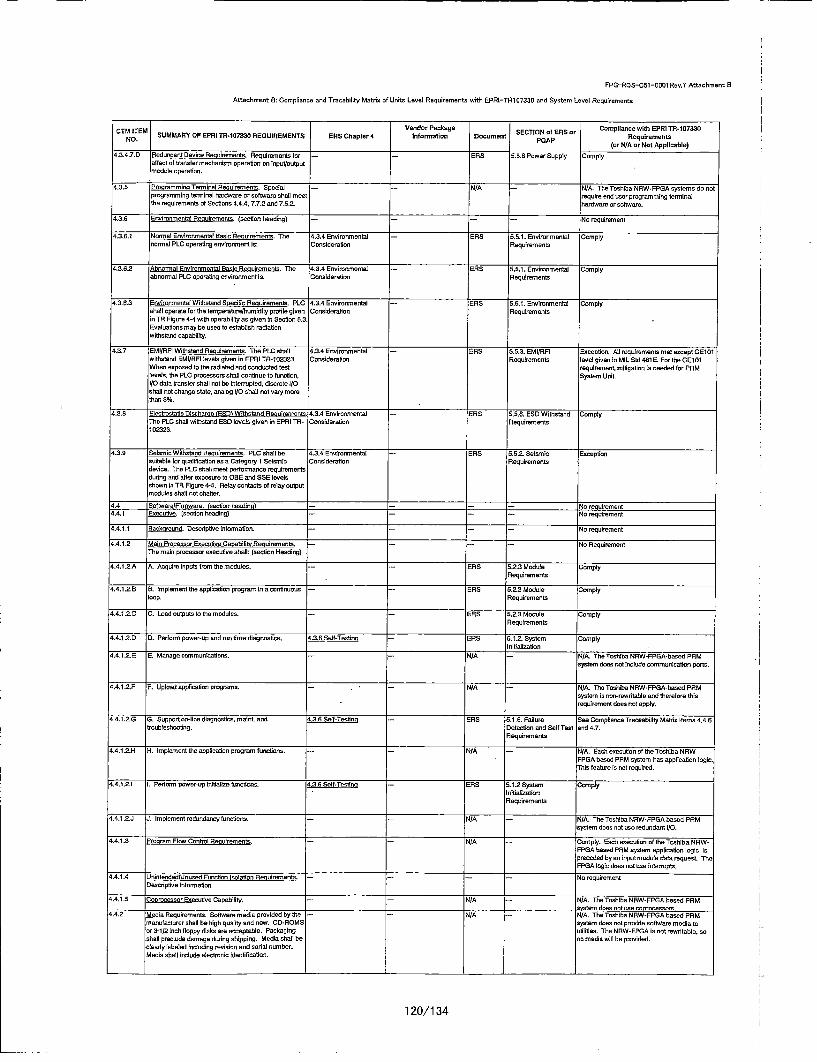
FPG-ROS-C51-S001 Reay. Atsaslvmnnt: B
Attachment: E: Compliance and Tracohtiity Mantlex of Unity Level Requiremnentslwit, EPRI-TRi107330 and Systemn Level Requirements
Cm TEM SMARoPEPIT-073rEQIEETS ESChpe Vendor Pactnage ElONo25or Compliance with EPRI TP-1 07330NO. totMR FoPI"R1030RQIRMNS ES hpe nfnlation Document SETOp~~ R rRequirements
(or N/A or Not Applicable)4.3.4.7.0 Redundant Device Reouirereontu. Reopuireroents for --- ENS 5.5.8 Power Supply Comply
affeot of travefer mechanism operation on hpaft/outputmodule operation.
4.3.5 'rooravmmlnu Terminal Revuiremnents. Spevial --- N/A -- N/A. The Toshiba. NRW-FPPA systamo do notprogramming terminal hardware or software shall went require end over programming terrninalthe reqoiremeots of -Setions 4.4.4, 7.7.2 and 7.5.2. hardware or software.
4.3.6 Ennironmental Reouirmnents. (socton heading) ....- Na requireeato
4.3.6.1 Normal Envlronmenta Easlo Reouirements. The 4.3.4 Eovimraorentul -ERS 5.5.1. Environmental Comply
normal PLC operating ernvirornment is: Consideration Requirements
4,3,6.2 hoononal Envimonmental Basin Roeuiremeents. Th1e 4.3.4 Enviromnrlental ENS 5.5.1. Environmental Comply
ahenorml PLC operating environment is: Conslderation Requtemnents
4.3.6.3 fnvironmental Withrstand Speciofic Rqiremenots. PLC =4.2.4 Eovironmental -ENS 5,.5.1. Enviroronental Complyshall operate tar the teorpaoturellrumidily profile given Consideration R•equirementsin TR Figare 4-4 with oparability au given is Sec-tion 5.3.Evaluations may be eyed to establish radiationwithstand cap abiliy.
4.3.7 LMIIRFI Withstand Renulrementa. The PLC shall 4.3.4 Environmental - OR 5.5.3. EMIIRRl Exception, All areuirements met eacept Ctr10withutsod EMPRRPI levels given in OPRl TR-1g5233. Consideretion Requiremeots level given In MIL Old 4616-- For the CE101When exposed ta the radiated end canducted test requlnrement, mitigation to needed for PPMlevels, the PL-C processors shall continua to fonction, System Unit.IO data transfer shall not be interrupted, discrete i/Oshall net obange state, analog I/0 shall eat nary morethan 3%.
4.,3.5 ittantostutio Diocharsa 10001 Withs'tand Renuirements 4.3. Enviromeantal - tRR .5.56. ESO Withstand ComplyThe PLC shall withstand ESO land~s given in EPRI TR- Consideration Requirementa1023333
4.l.9 Selsorin Woithtand Renairneonro. PLC shall be 4.3.4 Environmental -ENS 5.5.2. Seismilc Eaceptionsuitabla tar qoalitrcation an a Category 1 •seliuc Corsideration Requviraementsdevioe. The PLC shall meet pertormance requirementsdudng end after exposare to 060 and SEE landlsshown it TR Figure 4-ti. Relay sontacts af noisy ostpotmodulas shall cot chatter.
,4. taftwsarofironware. loection headinol ... .- No requairement4.4.1 Evocative. (santion beading) .....- Ru requirement
4.4.1.1 dah ud. Dreodrptive inlonmsatlon, -- ... . No requiremere
4,4,.t2 Mdan Processor Esecstive C anailit Reeriremeets. -- ... . No RequirementThe main procesoor esenulive shall: (seticn Heading)
4.4.1 .A A. Acquire inputs tram the modities. - - ENS 5.2.3 Module ComplyReqoirements
4,4.1.2.B 8, Implement the application program ina continuous --- OER 5.2.3 Module ComplyIoop. Requirements
4.4.1.2.C C. Loaud outputs to the modules. --- ENS 5,2.3 Modole ComplyR•equtrements
4.4.12.0, 0. perform power-op and run tme diagnostics, 4.3.6ESalf-Testine ENS bt.,2. System ,ComplyInitialization
4.4.1.2.2 6-.. Manage a•-moms otine. - - N/A - N/A. The Toshiba NRW-FPPA-besedI PPMapostom does net irrotde comemenication parts.
4.4.1.2.P P. Upload applicaflan programns. N -r/A - WA. The Toshaba NRW-FPGA-based PPMsystem is non-raordteble and therelore thesrequirement does not apply.
4.4.1.2-G 0. Support on-lice diognostirs, mardo. end 4.36 Salt-Tesfino -ENS 5.1.6. Pallure See Compliance Traneshility Matio Items 4.4.6troubteuhocting. Dete-cdon and Self Test and 4.7.
R oqalremeants
4A.41 .- H H(. implement the application progrran hodtionrs. - - N/A - N/A. Eavh eceoution ol the Toshiba NR1W-FPPGA based PPM system ban applivation logic.This lfeatre is rat required.
4A4.1.2.I Pentotn pemer-op ounelame lhocuces. 4236 Sell-osofno ENS 5.1.2 Epste CoplylIratiuiza~onRequirements
4.4.1.2.J .J. Implement redundancy tunctions'. -- -- N/A -N/A. The Toshiba NRW-FPPGA based PPMsystem does sot ume redundant h/O.
4.4,1.3 Proram Plow Control Renirements, -- -- N/A -- Comply. Eaob eueouton ofthe Toshiba NRWh-FPPEA based PRM system application logic ispreeed by an inpat module data request TheFPGA login does not uye intemrrpts.
4.4.1.4 UJnitntendodbnsed Fona-ion Isolation tRequirements. -- --- -- ho requirementDeuntdptive hiforreation.
4,4.1.5 Coorovessor Enecutive Canabtlita -- -- N/A - P1/A. The Teshiha NRW-FPGiA hosed PPMsystem does not mse noprcoessors.
;.4.2 Media Penauiremento. troftnare media providec op miemenulantarer shall he high qualitp end near. CD-ROMEor 3-1/2 Inch floppy disks are avoeptabte, Packagingshall preclude damoge tiudog shipping. Media shall becteadly labeled inaluding revision and oatal ncether.Media shalt incude eteotronin identifcotion.
N/A N/A. The Toshiba NRW-PPGA bused PRMsystem doens not provide software media teutiltites. The NRW-FPGA is not rewritable, soono reeds will be provided.
120/1 34
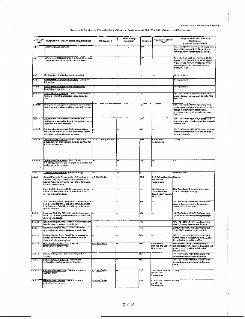
FPG-ROS-C51-0001Rev.7 Attachment B
Attachment B: Compliance and Tracability Matrix of Units Level Requirements with EFRI-TRi 07330 and System Level Requirements
ST Vendor Footage Campllance mwlt EPRI TR.-107T-30Cm PtM SUMMARY OF EFRI TR-107330 REOUIREMEN4TS ERS Chopter 4 lnforrmatfon Document SBCTION of ERS or RequiremeotsND. FDAF(or N/A er Net Applisebte)
4.4.3 Ladder tonic Poaciremonto. - -- Ni/A -.- NI/A. The FPPIA-bosed PPM system apptocatiorlogic mill be designod in VHDL, which Is aspecifc herdwmeo programming language.
4.4.4 Software Toxic Requiremonts. A tooi shall be provided -- N/A - /A. Th Toshiba NRW-FPGIA baxed FRMfor prograbmming. debogging end doxousootation. system is provided with an application specific
logic. Toshiba doean not teed to provide end
user software toxin. Theretor sulilty can rotmodify this logic.
4.4.5 Confqnaforlcn idsnfnalfictio. (section heeding) --- N ro requirmaent
4.4.nt sClonxi rwtion identilicotion Bachoround, Descriptive --- N ao requirementInfonnation.
4.4.52? Tontigcnatien Maneneroent Aide R uciremento. --- -- rNo requirementDescriplivo informtation.
4.4.ti2-A Confi uneti en Moria ement The PLC enecutive shtall - - h/A -NJ/A. The Toshiba NRW-FPIIA based PRMinciode a retnieable, embedded elect-cnic revision system deoe not have en equixalent of e PLCleveL cexeutire.
4.4.5.2.B Confinuration Mananemero. Configurotion intormstion -.- N/A -N/A. The To~shibs NRW-PPGA hosed PPMci contigurobte modules shall be ret~ovable in the field, system reconlfigorations ore onip accomplished
through mechandool decices (switches,pxxhbuttonc. etc.) Frovided on the hardwarechances.
4..4.5.2.C Conoiourotion Moanaemeno. Software nods for - N/A -N/A. TheaTosdhobNRW-FPGA basedFPRMmod ifying devico configurotdons shall provide measotrs system can vet modlfy device COnftiguratioss viat0 prevent enauthorized access, softwaere lost.
4.4.5.2-D Cosfiouraticn Manenement. PLC end support tools -- N/A -N/A. Thle Toshiba NPW-FPGA systems do cotshalt procidescapablility to expecot end record datebase need no implemoent data bases and modihiableintotrmation, inctuding program constants. program constants.
,4.4.S.S.E Centiocratice Masasement. All PLC devices that ri3.2ta Safetp Featurms -- R68 0.3. Software Complyinclude firmnware chal he martadwith anidenftiier that Peqoimm entsincludes revision lened
4.4.5.2.F Confiounetion Mdaneaoemotent FrpLfs with - N/A -- N/A.nedondancy. tools shall provide capability to costive thetcontiguraltoros eam consistenit
4.4.6 Cleonosties PRuimernento. /sevcon heading) .. .. - No nequoirement
4.A.6.1 Generot Diannesho Renuirements. pLC roast taco 4.3.6 Sait-Testtha ENS 5.1.6. Pailure Detactian Compltysufticient diagooslies end test repability to detect at end Salt Testfailures that couid prevest the PLC lross penfontiog ito Peotgemtentsintended safely fcoction.
Items 4.4.6.1.1 throughd4,4.6.l.6Omastbe covered by --- (Sec Compliance (Sec Compliance Traceabitity Meetlo; itemssn-line sell test, Items 4.4.6.t.7 end 4.4.6.1.fi most he Traceability M aiti 4.4.6.1.1 through 4.4.6.1.8.)covered is lesser-up tesns. Itwos 4.4.6.1.1 through
4.4.6.1.8.)
Stant team cbagnrasbos chacqnlo e ai dale ead/uts stat N/A -N/A. The Tashib. NRW-PPGA bused PPMbe Snnseocc lass for DC outputs and I/S optic or less systems does not animneset diagnosticter AC outputs. CapabTity to di~sables these diognoslios chang es in module eutputs.shall he provided.
4.4.6.1.1 Frocessor Stall. PorFPLCnwith redusdant pnm:oes s. - N/A -N/A. The Toshiba NRW-FPGiA-Beoed PPMthe PLC shall detect proeso stat acd hubt operation system do not inciuda redundant procssors.of the tolled procensor.
4..4.6.1.2 Poecutiee Proorem Error. Chest of eneculfee Obsmwure -- - ri/A -- N/A. The Tashiba NRW-FPGiA based PPMintegrity using a chectasun or similar lest. systemn does nst ase exesatie firmware.
4.4.6.1.3 Anshcstion Freoraro finer. Chech ot aeptasicaon -- -- N/A -- Complp wtith intent. A shectauro Is verifiedprogram integrity asiog a checksums or shmtiar test during FPGA fusernsp implementotion.
4.4.6.1.4 Variable MamoroyErrr. Read/W/rite memory tes by -- -- N/A -- N/A. Thle Toshribo NRtW-FPPA based PRMwriting ansi roadiog hash bitf patterns that test both . system doex sot ass wead/write memory, andstales of all bdes, or siml~an test. the appicatben caxnot be wedgfed.
F4.4.6.1.h Module Commonicoticn Error. Chech of 4.36 Seti-Tesfeq -EtiS 0.1.6. Failure N/A. The PPM system does sat include aseomounication data lstegrity. Detection asd Self Test communication port. However, the system will
Pequiremecto m osior optical serial treesmixolon data
4.4.8.1.6 Memory gallery tow. Chech of memory battery -- -- N/A -- N/A. The Toshiba NRW-FPG3A based PPMcapacity. system does rot use oeroery buttaedos.
4.4.6.1.7 Module toss ot Corstouroai~n. Per software -- -- N/A .- N/A. The Toshiba NRW-PPGA bened PPMconfigurahie rondoles. validate conhigoration. system does set one seftware configurable
moodules.
4.4.8.1.8 FaioureelfWatthdseTimer. Chech ofopeamtioneof 4+3.6 tielf-Tentinca E bS 5.1.6. Faillow Defeconlo Complywutohdog timer, and Salt Test
Requirements
4.4.6.1.9 Anlfcadsn not F~eecarno. Foillow no completeapplication program scan.
63.6 iaif-Teolnra EiRS 5.1.6. Pallune Detectionand Sell TautRequirements
Comply
121 /134

FPPI-ROS-Cgt51-00tRev.? Attachment B
Attachment B: Compliance and Tracafility Macnix of Units Level Requirements with EPRI-TP101335 end System Level Requirermeets
CTM ITEM SUMNOBRTIIh0EURMNBVender Package SCINoERor Compltaco mItts EPRI fTR-l07330NO. SUMRBPERIT-030REURMNS ES Chapteri4 Infornnation Docement Pleolemet
(or Nf/A or Not Applicable)
4.4.6.l.1O Analog Cutut not Pollowlng. Failureootaealog outpat 4.3.6 Solf-Tostios -- EPS 5.1.6. Palilure Exception. The Toshiba NPW-P'PGA-BasndIs follow commanded value. Cotootios cod Bolt Tost PRM system does not hove function to dotedt
Peqcircmntost filuom ol analog output follow commandedvalue.
4.4.6.1.11 AnoaloxInact not Rescoodno~n. Failure of aoalog input to 4.3.6 Solt-Tosino -- RER 0.1.6. Failure Exception. The Tcxhiba NRW-FPGA-Basodrespond to snpot signal. Detevtion and Salt Tool PPM system doex noct have function to dotedt
Pequirements failure of analog input to respond to input signal
4.4.6.1.iS Disvmste Inmd Oot vtotl Poondioc. Paltsre of 4.. efetn -- ENS 5.1.6. Failure E-xception. The Toxhiba NRW-PPSAhbaseddisxorete Inpuitoutyut to operate correctly. Doteottonacod Self Toot PPM system rioes not have futoniu to detect
Rfequirements the alouvre ot discrete lnpulyoatput.
4.4.6.1.13 Anvb.ellout of Calbrction. Analog inputor output 4.3.6 Self-Too_.n -.- ENS 5.1.6. FaIlure Comply. Thesa diagnostio feotures are onlypoint cut cI calibration. Detection cod Salt Toot input signalc.
Requirmmente
-4.4.6.1.14 PowerScpplyoutofroleranco. Powersupplyto PLC 5s4.3.6 Seif-Texttnq 5GOBHAS35PPM System ERS v.1.6. F011um Detection Cwnplyixtetrrpted or a cttassis power supply module fails. Equipment Coolgo and Salt Tedt
Spailetiicabo Requlrementsu3.3 Unit Power Supply
4.4.6.3 Os-LUne SoSf-Toot Pevolrent. Ox-tene seti-toots -- - {See Cempliance fSee Compliance Traceatidlity Matrix Itemsshall covcr of least items 4.4.6.1.1 thrcugh 4.4.6.1.6 Traoeability Matx 4.4.6.1.1 through 4.4.6.1,6.1above. Pasuita shall be made ovallable te the Items 4.4.6.1.1 throughappliration progress. 4.4.6.1.6.)
4A4.6.3 ouwer U Dianostira Ranuiremente. power up .- - ERS 5.1.2 System Complydiageostics shalt include all ox-tine self texts. loitalizationcontiguradcn noritication, and tact of failure to complete Plequlrmmeotea scan. Appficcatin programs eoecition shall beinhibited it power up diagnootise dtctat a failure.
4.4.7 Date and Dots Base. --- N/A -- N/A. The Toshiba NRW-FPPSA based PPMcystem user deicOnod program conelests are notsupported. The system does cot have a
resident data base.
4A.6. Other Nox-Ledder toic Psorammia Lenuases. -- -- N/A ,- N/A. The FP'GA-bcxed PPM system applioahorlogic mfil be designed lo VHDL, which iso•speolic hardwore progrrammng banguage.
4.4.9 3 uencen of Events Proesalno Pouirerante. - - NIA -- N/tA. The Toshiba NiRW-PPGA based PPMsystem it provided with an applicationt specific
legal. Seqoece of events logic ixsentanecssary.
4.4.10 systemn lotoratlsn Roalxemeuts. Ao appropriate level -- (See Comptiance (See Compliance Traceability Mantris itemof system intacgraiton and integration tooting shall he Traceability M atix tam 5.2.C.)epplied to the toot spedimen and TSAP. 5ZC.C)
4.0 HeedaohinelInterfacetf-MII. (seitioobheadiog) ---- - No resfuiretoent
4.5.1 -fuemetathine Inletoed IhM Banhk und. -- No -h requirementDescriptive lnformation.
4.0.2 Pcutaaroeoets for HemerdMachise Inteetface Funotions. --- - - tic reqcirementD esotiptine Infornation.
4.5.2.A HIMI Ponctioss_. PL-C shell coppedrtswitohing caslop -- -- N/A -- NfA. The Toshiba NPW-PPGA booed PPMcontholler between manual andi eucatio nia seitch system aypt icaticon dcox inotnlude loopnspote. Per crtrutm coops switht iotagral acin tonhotieos lsgico.,etnm c treevtn,Ndentsctt-ense,nntad
4.52-B hMIFvnofex. PLC shallisappcetsetpoteofcaustmenta -- -RlS ti.1.3 NantinalSystert Corspty,siaowith onputs. Adjasbnoens sthait ined le ilecreasa, Satpotntedenreasec end rote tdna ofrtoce setewe nt_________
.,5OZC HtMI Punotions. PL-C shutl suppedt manual inttraboe at - - N/A -- NlI. The Tashiba NRPW-FPGA based PPMequipment eta seltoth inputs. PLC shait support system appltistion 1ogic dccncl require manualIdstecion ot manually Inditiated equipmoent. initiation of equipment.
45.6.3. HMI Functions. PLC shall suppodt disploy of stoles ot -- -RbS 0.2.3 Module Comply'discrete and continuous naive p'arooetems vie Requirementsconnected devivc.
4.52.E HMI Punctions. PLC shall xuppordsending inforration -- N /A -- Exception. The Tsehdba NRW-FPPA boxedta a seia pert device. loformantio sentsshatt solace PPM system does not sappedt sendinginput, Output and hoe eadtable exis co-rare intarrnaton teea serial pert devise.:diagtmstico, seqoence of events (SB-E) data, cod
4.0.3 Rfesuiremests far Isteroative Peetures. The pLO shall -- -Nc/A - NlIA. The Toshibe NPW-PFGA Saved PPMptaside mechaenisms to prevect unvuthoriced acomess 5 harcdware it pravided with an ayppolicstoor Inadvertent as of ox-line funotiovs, specitic logic that tassel be modified. This
texture ic not requIred.
4.5.4 Rqcuirements far Operatur Mitesn System PRvnonse --- ERS 5.1.1 Easlo ComplyJ3rues. For any operator aetion that requires PLC Peetormancetontinmation, tire PL.C shall include teaturem to enable Rtequirementetony arnation wliehi 0.5 sesends.
4.5.6 DIstor Rooalremente. Status shall he easilynitslble. -- -- RS 52.3 Module CemplyRequiselenote
v.0.6 Alarm Provesuine Poviremenso. Descriptive .... . No requirementinfornaitosr
s.5.6.A Alear ptoexo. pPLcshatllhcveability tecompcar -- -- EPO 0.1.1 BasIc Comsplyenpvts or derived oararesters to setevinte. Performnene
4.B.6.B diane Procsrains. PLC shail have oboity to eatch an -- - ERS 0.1.1 BasIc Complyrlerm condition and reset boxed on valam reset perormane~v
4.5.6.C die roess. PLC shalt have ability to hush an -- -- N/A -- Saceytion. The PPM Syxtem provides vices____ output indicator.,___________________ signals to the plant annunciatcr system, which
122/1 34
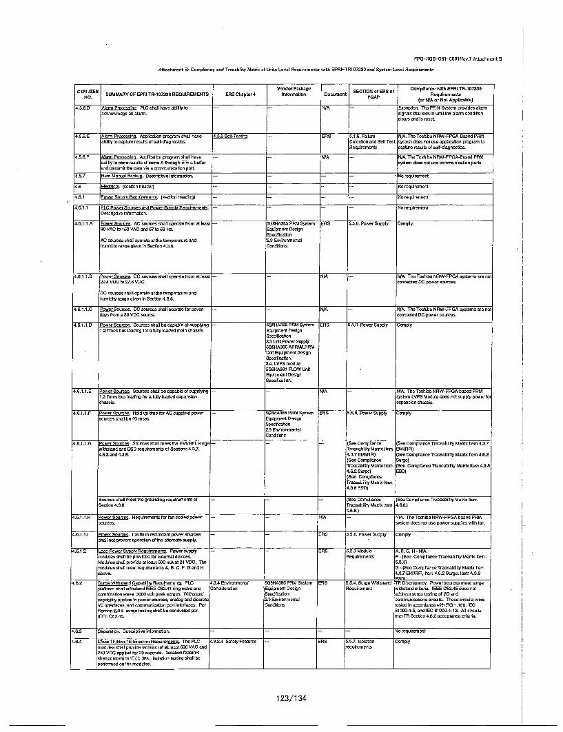
FPG-t3S-C51-0001 Rev.? Attach ment B
Attachment B: Compliance and Tranohility Matrie of Univs Level Requirements With EPRI-TRi107330 and System Level Requirements
CsIEMVendor Package SCINaS5or Compliance with EPRi TR-1B733I1NTM ITM SUMMARYVOBPERI TR-107330 REQUIREMENTS ERlS Chapterd Intformation Document SETO fESo Reqalrerments
(or N/A or Not Applicable)
4.5.6.D Alr mnvn. PLCschatlhave ability to --- N/A -- =Excptioc. The PPM System provides alarmnacknrowledge av alarm., signals that lock in until the alarm condition
clearn anid Is meset.
4.5.6. •alone Processvng. Application pmrogram sholl have 4.3.6 Se~l-Taetine -- ERiS 5.1.6. Failare N/A. The Tonbihba NRW-PPGA-Baoed PPMability to capture results of calf-diagnostico. Detection anqd Self Test system does riut use application prcgram to
Poequiremeets capture recuits of celf-diaqnonfce.
d,.t6.F Alanni Processing. Appilcatian programn ohail have -- -- N/A -- N/A. The Toshiba NRW-FPPA-Boned PPMability to otere esutiho of Sawn A through Rina hattufer syslem does eat con ccmmcnicadion potty.and zacomiti the dato via a cammuLoiatice port,
4.6i.7 Hland Manual Bechua. Deocriptive information., - -... . No requirement
!4.6 Electrcal. (unction header) ......- No requirement
4.6.1 Power tati Retnirenments. (scandor heanding) -- -- .I .. . Na requirement
4.6.1.1 PLC Power Sources and Power Sonnle Reouirements. -- -- - -- No requirementDescriptive informotgon.
4.6.t1 .. A Power Soucews. AC sauoure shall aperate fnrom at leant -- 4lG8H4A85SPRMSystem EPS 5,5.8. Power Supply Comepiy.86 VAC to 1580 VAC and 57 to 63 Hz. E~qudpmect Design
Spedf/caadonAC souroes chatl operate atthe temperature and t9 Eanvironmentalhumidity range given in Section 4.3.6. Coed/loan
4.6.1,1. ,B poer Soorces. DC sucrcen shall operate dfmn at aeont -- -r/A -Nr/A. Tha Toshibia NRW-FPGA systems are nol20.4 VDC to 27.6 VDC. connected DC power sources.
DC nources shail operate at the temperature and
humidity range divan In Section 4.3.6.
4.t.1.1.C Power Soomes. DCcacrcensshatlaoperatetforseven N/A -- N/A. TheToshiba NRW-FPSA systemn are nutdays from a 30 VOC scarce, c-onnected DC power souares.
4.6.1.1 .D Power Seames. Sourmesohatibe capabieaofesppinirg --. 5GeHA38tdPRM System ERlS 5.5.6. Power Supply Comply1-2/tlesn b us loading tare ta lly loaded main olsassin. Equipment Danlgn
Specificotian3.3 UnIt Power Supply5G8HA366 APPM/LPPMUaot Equipmenet DesignSpecifiation.3.d. LVPS moduletOBHA3dt FLOW UnitEqalpmect DesignSpedlication.
4,.6.1.1 .6 Pumowe omrce. Soumes shatllbe capabte ofsopplyng --- N/A -N/A. The Toshiba NRW-FPGtA based PPM!1.2 tOmes ban loadng tar a fully loadedf eapanaton system LVPS Modute doean nrot supply power fa•
cihasoin, expansion chensis,
,4.6.1,1 .P Power tvurmes. Hold upt6mefor AC supplied panar -- 5StHAS85PPRMSystem ENS 5.5.8, Power Supply Complynources shall be 40 moan. Equipment Design
Speciticaagn2.9 EonironmenralConditions
4.6.1.1 .0 Power Saumae. Soaownn ha~limeetfthe EMI/RPI, surge- -- (See Compliance (See Compliance Traceability Manly from 4.3.7withstand and ESD reqahremeets ef Sefc~ons 4.3.7. Traceability Matriu Item EMI/RFI)4.6.2 end 4.3.8. 4.3.7 EMI/RRt) (See Comptiance Traceabildty Ma~im Item 4.62.
[Sec Comptiance Surge)Traceabitity Manxia Item (See Can•pl/unmTraceabtidy Mar/u Rem 4.3.64.6.2 Sarge) E5D)(Sae ComplianceTraceabildfy Mat/ax Item4.3.8 ROD)
Sources shall meat the ground/ug requirem ents at .- --- (See Compliance (San Compliance Traceability M at/nx ItemSectioc 4.6.6. Traceability Meat/c Item 4.6.6.)
4.6.8.)
4.6.1.1,.H Power Soumces. Requirements tar fan catted power -- N/A -- N/A. The Tech/la NRW-FPGiA hosed PPMsources, system done nut ace power supplies with tan.
4.6.1.1 .1 Pewer Sources. Faults is redorotant power sources -- ERlS 5.5,8. Power Supply Complyshall nout prevent apertaion t ri treceattse supply.
a.6.l.2 beoo Power Sect Re lrmerns. Pawersapply -- ERS 52.,3 Module r, B, C. H - N/'A.modules chatl be pint/dad far external udenics. Requirements P- (See Compliance Traceability Matim ItemModules shall provide at least 500 mA at 34 VOC. The 5.3lt)modules shall want requirements A. B. C.E S.Gand H 0 - (See Compliance Traceabtlity Met/vx Itemabove. 4.3.7 EMIIRF'I, Itom 4.6.2 Surge, item 4.3.6
4.62 'tame Withstand C ablyhRilr~eoments. pLC v.3.4 Envirortmentat LGOHA385 PPM System UPS b&5.4.thurge Withstand tRtDiscrepancy. Powersoaurcesmeet surgeplatorm shall mfthstand IEEE C62S.41 ring wave and Conslderation .Equipment Design R~equirement withstood criteria. IEEE CES.4t dues not:combinatdon owove 3000) volt peck surges. Witnstand Spedlicatdon addiesn outgo tesdthg at I/O andcapabtity apptes tupower socroes. anatog and disarete 3.9 Earvinonm entai cemmunications cimrcuts. These ciroif were/1 interteces, and cammunicadan port interfaces. Per C.oeditons tested in accordance with PG 1,180. IECSection 6.3.5. cargo testing shall be corducted per 81000-4-5, and IEC 61000-4-12. Alt circuitsIEEE C62.45, met TR Section 4.8.2 acceptance criteria.
4.6.3 Seaato. Descriptive inflormration. -- --- -- Na requirement
4.6.4 /)tus 1 E/Non-1E 0Isolation Ranvirements, The PLC 4.3±24 Safety Features - ERS t.d.7, tsoiadion •Complymnodules shall promide isolation of at leant 600 VAC and requlrementsS_50 VOC applied tar30t seconde. tsolation teaterenshall cartoon to lESS 384. nsotation testing shall beperformed an the modules.
123/134

FPG-RQS-C51-000f Rev.? Attachment S
Attachment B: Ceorpliance and Tracakility Mutely of Units Level Requirements with EPRI-TR1 07330 and System Level Requirements
CTMenformPcatgo Douet SOtNo B r Compliance with EPRt TR-157"33t
C, NEM• rl. SUMMARY OF E'PRI TR-10733t REQUIREMENTS ERS Chapter 4 Ifrain Dcmn ETOp~o R rRqieet
(or N/A or Net Applltable)
4.6.5 Cablelhiino Reocirewente. Manuteuturer shall supply - -ER/S 5.2.4.2 System Cotilet Complyall PLC hardware Intevconnecting neabling. All cabling und Connectersshell be suctble fur UL Clout 2 serv~ce. Speslficolly.withstood toting shall tie larger sf 3 times the signallevel sulftge cr 150 eu/Is, Temperature rating shall he60=C or gmeatet. Vender shall identity the quantities efPVC type aime and cable used in the systemt.
4.6.6 ersivotion Reouirewents, Modules shall he able to he -- -- N/A -- Euception. Suck Facet modules ar'e cable-remoVed withovut disuonnectirrg hield wiring, connected, so module removal requires cable
lier~snnscltlvFeatures shall be provided to substitute test sfignals or -- -- -RS 5-2-4.5. Terminationr Complymonirtoring iesttrunents tor field conetetione. RequirementsConnectors to the PLC shall have poultice hold deowmechunisms.
Coacactom and terminutioes to the PLC shall be -- -- ES ti.24.6. Termrinution Comply
q ua•Shd with the genetic PLC. Requirements
4.6.7 Bobn oe. Descritiv~e istormation. -- -- -- . - No requirement
4.6.6 UmucdisnlShieldino Retuiremesis. The PLC -- -- ERS 5024.5. Comeplyequipment shall west 5EE61050 and EPRI TR-1 02323 Graundlng/Shieldlnggrouvdsig requIrements. Thi incoludes supporting Requinementsonnctrtlon to single point, mutio-paint and fileatngground systems, and pmovidrng separate gmoundconnection points con each chassis for AC ground. DCgraced. end signal ground.
Thu PLC equipment shall meat IEEE 1050 and EPRI ERS 52.4.5. ComplyTB-1602323 shieldisg requirements. Thin inludes GroundlnglShieiringpmouidlng nhleldisg cassaction points for thaI/f modale Requirenentsfield tesninatioes.
4.7 Maintoennca. (section heading) - --- -- Na requirervest
4.7.1 Mealntenasra geukoround. Descriptive informetion. -- -- -- No requirement
4.7.2 lannnosisthuli-ln Testabtit Beutmments. --- --- - Na requiramentDesuriptive inolrtatius.
4,.7.3 Mednln Ree laewent Benurweents. Thle PLC shall 4,.3.5 Maletenecc ERBS 5.8 Malrrtenance Complycastais features to aid in madule replecemouf. Preisioslr Requiremenis
The malntenance manual staalcontoainadesuriptancof - - ERS gt,3. Users Manual Complyany hardware aconfguraticn item for each m edals.
the medula busd domes shall be easily aoneeslble and 4,.3.5 Mbaintenance -- RBS 5.8. Maistenance tnmplypmslde euas of rmocval and rienstolltisfo. Pomisimrs Requirements
4.7,4 PreeentiveManeisrncnr Reouresserts. Equipment - rRS et1.. Users ManlUal Lemplymacuals shall caches provetnce mainteneanceinfarmetias. Pveevaniu malntrenanoe strati else hnlude
4,7.5 derveillanee Testieg Resuirernents. The PLC shall - ErRS hB Measnteance Comply with erecnt Ailthough the Toshibasupport I1E5 338 suwneilianus testing. R•equirermeoto NRW-FPPA based PAM system does out
4. support the listed abilities, the herdmaee cartsupport IEEE 330 Surcellanue Testing.Including Chancel Checks, CalibrationrVotihicutios, Punetlosal Tests, Timrne RespanseeTasts, and Aualcg Trip Signal Tests.
14.7.6 Olut SanasslControl Decices. Descriptive -..... .. Na requirement
:4.7.7 r •tBnlraa~t. Thu PLC strat napport intecheing -- - rI/A -- dicepilcn. The Teshdba NBRW-FPGA basedgO moidues edth be-hplarm pawer applied. Low powen PRM systwe doss not support as-luse removalmedudas shell support rretoval wigs fist d power apphed. or insthelation ot components.When Outpu modules ame rereoved fmom the hactrplarmthe stae• ci the outputs should he heoms.
4.7.6 Maurratctorer Systew Ufe Cucie Maletenaeca. (seutiar -.. . . No requirementheeding)
4.7.6.1 parstR Alanewest Uife Ced Reoudrenects. The 4.35B Masntesancre -- ERS 5.0 Malntesance Complybaealine consfigourtior of the quaatthed PLC shell he Provrisios Requiremensf
Records shall be mahrhened for resisn/c history and 4.2.5 Mshsarwre a,' -- ENS 5.8 Maintenance Complycheoges. Prev/s~ces Aeqairemests
Recasts shall be malntoined far tracking toifases. 4.3.5 MantlereraCe -- ENIS 5.6 Meintenartce Complyprovisioss Requirements
7,Testing shall be performed an necesary to maletois a 4.3.B Mainfenancae -- ERS 5.8 Mahrtenance Complyqualified platfues basad an future revisonys ur Previsions Requiremensf
The intormatiun necssary tufih thene task shall be 4.3.5 Mainrtenanrce -- ERS 5.8 Maintenanra Complyubtained from manfctunumr. Provisions Requiroesets
4.7.g.2 tCornanent Acino Anuasi Bs Rairmnents. A periodic - .- inNS 5.A. Desigs Life ComplysurvellanJce and mainissance interval shall bedetermined yen I1655323 to accoust lun acy significantaging weuhanisms.
4.7.8 Malntaenare Homes Peutors. Desudtipvecinforsatiun. --.- -Na recqulrement
ti.7.9J.A Speie/a PLC Menu/acturer Ecuiement. The - - . /A -. N/A. Na special toois inquired isr inutimemanufactumreshall precide danumentutios for PLC malntenanue.support equiprnerr
124/1 34

FPG-R05-C51-0001Rev.7 Attachment• B
Attachment 9: Compliance and Tracability Matrix of Ueitn Level Requirements with EPRI-TRI 07330 and Systere Level Requirements
Cu TM SMAYVendor Package SETO tES~Campliance rath EPRI TR-197330NO. ITM SMAYOF EPRI TR-I9733O REQUIREMENTS ERS Chapter 4 Information Docamentg ETO of2A (aSorReNqAirenotsApicbe
4.7.e.R Tool gcciment Connectieon. Test equiproont -- -- tiffS 9.1.3. Usern Maccal Complyconnectiono sholl be nupported by dounantation codharriwaro, including iolerconnoction devices. The;manufacturer shall provide any special ionstrution farcoo of test equipmentl connectices.
w.7.9.C lob Aids. Aids for operoting the Pit eqalpment shall - -FkS 9.1.3. Users Manual •Complytoeprovided.
4.7.9.0 Hal cres Neip screens for software coed to - N/A - ri/A. The Tankibs NRW-FPPA systernsdo notsupport mainotenacce shall be provided. loirode software to support tnalntenance.
4.9 ReooirernentstforThindParvfStb-VandvrlItems, All --- ENS 5.11. Requirements for Coreplyitems provided by soft-vendors or bhird parties shall be Tird party/Sub-Veedorsubjected to all applicable requiremeets and tests, ItemsComp abbibitiy of operation with the pLC shall bedemonstratad through tests.
4.9 Ote. (section heading) -- -- -- No requirement
4.9.1 lets Handlien and Cromounicaffon Interface Overview. -- ---.-- . No requirementDescriptive intormatkon.
4.9.1.1 e.iheral Communicotion Reeuirements. The PLC --- -N/A --. N/A. Toshiba NRW-FPPGA booed PPM oystersexecutise con/o r application software tools shall provida does eat once aperipheral comnmucicatlon port.featores to prevent coo• of serial communibcotian fromdegrading tire epplioction prograre. Communicationoverhead time shall be deterministic. Peripheral•ranmuaicalions shall support at least WOO0 charactar
communication buffers. (Nate: 1 character-i byte. Areal vadiabla ones 9 bytan or eight ohrarnctrs). Serialcommunications shall support checksum (or eqolvalent)data quality checks. Reqaireroonro for redundantcommoniocton hardware.
4.9.1.2 PLC Peer-tc-Pear Commoubatic'on Ranulrements, - N/A -N/A. TheTonhiba NRW-FPSA boned PPMPeer-to-peer linb shall meet requimremets of Section sysfam does net one poern-ta-peer4.3.4.4, eocept item B. Cormaluniaton time shall be commuoicatico links.daetenninioto, Conrmunicution errors oftall ant affectother podtios of the abppIcatbon progrnam or Inh~iti the=PLC noon cyele, Ocuone for cemmunluated data shallbe supported and queuc status shall be avatiable to thecomreuaicatioo program. Loss of cuenmuaicbatin shallbe detected and made avallable to the applicationprogram. Use of the peer-ta-peer caommubctioan lobkshall support the response time requirement given leSectien 4.2.1 A.
4.9.3 Overall Stnem Senorit Peire-nents. Swritching the 4.4.3. Calibration -ENS 5.1.5. lrstrument Mode Comnplymain processorfrom RUN mde•teoether meods shallbe by haylock owitsh.
Features skall ensure that redundant caomponants -- -- NA -N/A. t•n Toshibe, NRW-FPPA bonedf PPMoperate in the name mode, and that program changes systemn dses not one redundant preoesors.are loaded into all redundant preosesso.
Prevlstons shati prevent modification of the apprioatian -- -- rN/A -N/A. The Toshiba NRW-FPGA based PPMprogram and operating oysters while the pLC in an-lioe, system doees not treed m odification of the
application logic, cod da not use an operatingsystem softtware or firooware.
4.9.3 Heorthect RP uls~enata;. The PLC shall preside --- N/A -Edceptios. The Toshiba PPM hardware doescapability to antimate a hbea~rtbear" aeternal to the PLC. set inclade an atailable output point to operate
an eseal hbeatheat indicator.
4.9.4 lazardous Motedais Peechernet. Material data -- -- ENS si.10 Mater/st Coreplysheets shall be prmlebid for all haaarousw reatertials I requiremeents
si10 Sh ihinno end Handline Reeuire•mnnte. packaging end -- - ENS b, Packaging and Comply .shippieg shall be in accordance with ANSI N45.2.2. Shipping
4.10.1 p'aoaninn Reeairementm. Descriptive infoneotion. ---...... .. Na requirement
4.1 0.1,.A news Shinn Shall be packsaged to avoid damoge or --- ENS 9.1. packogieg Complydogrodatioe due to various environmental cod handling Rlequirementsfactors which may be enon•tened daring shipping and
4.10.1-.B Itm hir paclargiog salicdeeact - - ENS 8.1. Packaging ComplyI ateralsatonas nidrd. Requirements
4.10.1,.C rasSroo Itrns shallbehwpacted for decntiteso - - ENS 8.i. Pacitgn r.larnplyprior to packaging. bores net ironediatefy pactraged Requmnnettt•hail he eseteeed heom eenwwinn ____________
4.10.1 .0 Itemns kioe Ccohioning shallbe providedto protect -- -- ERS 8.1. Pankoging Comnplycaboint shock and nibration. Resuirements
4.10.1 .E Itm h ,nd Items and containe~rs shall be marked -- -- ENS 8.i. packaging ComplySbt acaropatea identification. Requirements
4.10.1. ,F oo hice. Copies of packing lists skati be -- -- ENS 9.1. packaging Complyi ciuded with each canon shinned. Reeuirements
4.10.1 .G h ems Shi~oed. ESD sensitiveaitwns shall be -- -- ENS 9.1. Packaging Complyappomonatelo pneok ,e hordlod cod marked. Reeuirements
4.10.1 .H Itm•hce. packaging shall be suitable for -- - RSo 8,1. packaging Ccemplynovement coina hand toruks. Recuiremnents
4.10.1.1 Items Shicoe. Special handling er storage -- -- -RS 8.1. Packaging Complyareuirements shell be marked non the cantainers. Recairem enta
4.1O.1.4 Itm hoe. Seenteotian4.ti.2forrequinemantsfnr -- -- N/A -- N/A. TheTehsbabNRW-FPOA based PRMsoftware stoag~e media. system dons net provide software media to
utilities. The NRW-FPPA Is cot rewritable. sono moedi will be provided.
4.1 0.2 Shiooins NRcirements. Requirements for made of -- - ENS 9.2. Shipping Complyshippivg, one of fully enclosed vehicles, special Rlequirementshandling cnd stacking instructions on necessar, and
___ nt_ .n moicrm~irnna nnl n~rntw.O,,annam4.10.3 Sterene Recalnementa. Storage and shelf life --- ENS 8,3, Storage Comply
req___ uiremeants shall be provided ton all PLC tiems. R__________ ____ enuirenments -_________________
125/1 34
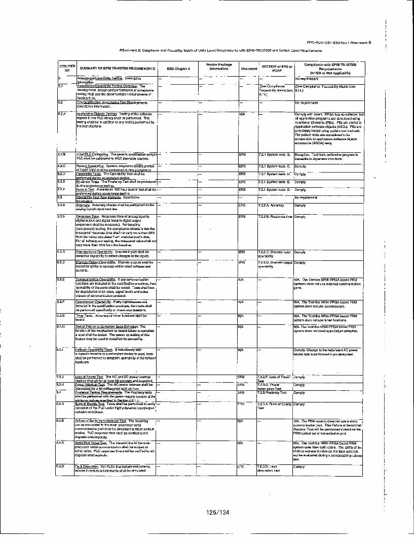
FPG-RQS--C51-50001Rev.7 Attachment B
Attachment 8: Compliance and Tracabilicy Matrix of Units Level Requirements with EPRi-TRI 07330 and System Level Requirements
C-tiTEM Vendor Package SCINo Sor Compliance with SPRI TR-153330C .M SUMMARY OP EPRI TR-107330 REQUIREMENTS ERS Chapter 4 Ifaormatioo Document PE'O~pApofES Requirements
(or N/A or Not Applicable)5 Ancconfucelo]oerabilrcTestia. Descriptive --- - Na requiretment
intormation.5.1 nccenlancelOcerahiiitnTesgin Overview. The - -- (See Compliance (See Compliance Traceability Maitri Item
develtyment, design and performance of acceptance Traceability Mutric Item 8.14.)tenting shall one the rioumentation requirements of 0.14.)Section 8.14.
5.2 t're-OuatlinctionnAcceotote -cTent Rouirrements. --- - -- NeorequirementDescriptive Information.
5.2A Aolinotion Obinorn Tenton. Testing of the software -- N/A Comply with Intent. FP5A han no software, butnb/note in the PLC library shall be perfconmd. Thi all appllcation prograrrs are developed acingtenting chall be In eddltiov to any testing perfomled by Punctional Eloments (PEn). PEn are stinior tothe reanofactorar. Application software objects (ASOn). P55 are
complotefy tested using paoem tent methadm.The pattern tests ear considered ts becomparable ta application software objectsacmeptonce (ASOA) tensS.
52.B Inta L eirta. Thle generic qualifhcatone canplo - - ERiS 1.2.1 System tests S. Excception. Tonshibacs calIbration program isPLC shati be catihrated to NI ST traceable souresn. trceable to Japanese standards.
5.2.0 System tntenratcnq. Systent integration tenting pntfoo -- -- ERn 7.2.1 System tents C. Complyof TSAP V&V shall be nertormed duties anco-ntonce
5.2D Oorhlisat. The CperabiltityTest shafllbe -- -- ERS 72.1 System Iestc 0. Complpperfarmed donne acceptance testens.
h2hE tieeo et. The Pradrreny Test shalt he pertormed -- -- ERS 72.1 Systeem ntest E. Complyaumino eccanotnc-e tectnv.
.2.F tomn-In Tent. A minimem 352 hour bum-In test chaRl he -..... bBS 7.2.1 System tents 6. Complyoerfonmed dudeno aconotare tendonq.
5.3 teorabllt Test Reulimments. Descriptive .....- No requirementinfnormtionn
5.3.A Accuracy. Accuracy chreche ahall be peortened an the -- -- bRS 7.2.2A Accurocy Complyavatog inpct/nutput medides.
5.3.B Renns• m. Renponsetime otanalog input to -- - Ens 72.25B. Response time Complyd~gitel ostpot and digital input to dlgirof oatputsequnenes nhetl be measored. Par baneline(acceptance) tenting, the acceptance cierida Is that themeasored response lime shall not very mome than 20%Yfram the value calculated from rneaufetmr's data.Per all subsequent testing, the meanared value shall notnary more than 10% tram thm baselne.
i.3.C Discrete Inest Ooercbliti . Discrete Inputs shalt he -- - EnS 7.2.2 C. Discrete input Comrptytected for capability to detect cbanges in the inputs, operability
5.3.0 Discrete Ocuto Onerabitlyc. Discrete octputs shall he -- -- ERS 7.2.2.D. Discrete natput Complyrested tot abitiy to operate mitste coted voltages and Operabilitycorrects.
5.3.E CemoveuicationeOnerabilite. If any communication --- N/A -NIA. Th esbhiba NRW-FPPAbooed PRMfunctions are iholuded in tire qelaliftcation envefope. Phrc systrers does neon slemaxtera communIcationcperahility of the pores shalt be tested. Tents shall look ports.far degradation In bit rates, slgeat levels and pose•shapes of coromunccotion protocol.
ti.3.P Coernoncsor Onerebilit. Ifoany cnproaess are -- -- Ni/A -N/A. ThteTeshibaNntW-FPGsAbesed PRMlincludod in Pro qualification enoelope. thee tests shalt I system does not ace coprocesors.bde periormed specIfically an these coprocessors.
5.3.G Timer Tests. Acouracy/offtimer funcioensshaitbe ,- -- N/A -- N/A. The Toshiba NRWt-FPGAbased PRM.tested. system does not ace timer funtcens.
5.3.H Test of Pallure to Coreglee Scon Detectoen. The -- -- ri/A -- N/A. The Toshiba NRW-FPGIA based PPMfunchaon of the modethanil to detect fedorae to comeptete systemn does not sned scan failuro detection.a scan shalt be tested. The power op testie of tidet eatuare m ay be toed to ectoitsish its operabftty.
5.3.1 Fallsoer COerahfitt Tests. If redunatrwith - N/A -Comply. Change to the redundant AC powerautomatic transeferto a redanderrt device Is snor, tests sourme test is performed in prurlency tent,shall be performed to establish operability of Pro taitaovehardware.
0.3.J Lose of Power Test. ThneAC and DCponersoomes -- -- EBS 7._2.F.. Lass of Poweer Complyshaolt be shot off tor at least 311 seconds and meaonlind. Test _________________
0.3.K Powerlvntemsit Test. The ACpower sournes shtlbe -- -- tEB 7.22.G. Power Comply'rnterrsofed for 0 40 millisecornd fold-ce time. Interruontin Tent _________________
5.4 Prade Testi uremmento. Tire Prdency taste - -- tenS 7.23 Pisiderroy Tes-t Complyshalt he performed with the power supply seances at the
5.4.A Burst of Events Test Tents shat he performed to nerify --- EBS 7.2.3.A Surst of Events Complyoperativ of the PLC coder highly dynamic irpotnoutput Testnotation conditions.
P.4.8 Peilure nt Serial Port Receiver Test. The receiviog --- NM N/A. The PRM system does nst use asetialdevice connected to the main processor serial communication port. This Pallure cf Setial Podonmmrunlcation pcrt shalt be simulated ta toll in nedoes Receiner Test will he perfooned insead for tire
meden. PLC response timo shall be verified to not PRM optical serial P~anseebsiseo port.degrade uaecoeptably.
P.4i.C Semia Pcrt Noise Test. The trano•nit line to the male -- - NA -N/A. The ToshibaNIrRW-FPPA based PPMprscessor serial communication shall be sob/not to system toes fiber aptie cable. The ability of thewhite noise. PLC response time shall be ventfed to not PPM to withstood noise on Pro fiber optic lickdegrada onacceptably. mil be evaluated doting a comparable prodenny
0.4.D Feult Simolation. Fcr PL~s that Immclude redandanoy -- -- Ego 72.3.0. Feolt Jomplyfailures In redundant elements shall ho sim ulsted. Simulation Test
126/1 34
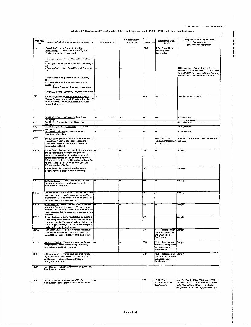
FPG-RQS-Cttl-0001Rex.7 Attachment B
Attachments,: Compliance and Tracahility Matrix of Units Level Reqairemente with EPRI-TR107330 and System Level Requirements
CM EMVendor Package SCONnESor Compliance with EPRI TN-107330
NOM r[M SUMMARY OP EPRI TR-1 07330 REGUIRE•MENTS ENS Chapter 4 Informatien Docament PETOAPf RSo Reqairtements(or N/lA cr Not Applicable)
5.5 Onerabilitvlude eov gnse Anelcabiite ENS 7.2.4. Operability andNeoRerurt. As a minimem, Operabtity and Prudenoy TestsPruriency tests shell ho perforered: Applicability
- During aeceptance testing: Operability- All. Prudency-Atl- Ocring environ. tesiting: Operability-All. Prodency-All- During seiuwin testing: Operability- All, Porudnny- -- TN Dlscrepaxoly. Doe to short donation ofAll coimmIt SSE tools, and special not-op requited
for the EMI/RI oests, Operability cod PrudenoyToots cannot be certoernod at these fec es.
- Alter seismmn testing: Opeabt{loy -All, Pnodency-None- During EMIIRN touting: Operability- All exceptanalos 11O
chechs, Pnjdcncy - Only banat xl events lest
- After 650 tentng: Operability - ASi. Prsdencp - None
5.6 tXoclatiee Softwcre Obiecto Ac~enterru lASOAt -- -- N/A -Comply, vee Section 5.2.ATestec. Reeuirements for ASOA teesfn. Based on NiAtre ASOA tostino Sonrion 5.6r ureoreneot wre not
O "Oualtilnoton Tesgne ond Anoleis. Descriptine -- -- -- No reqalrement
0.1 txaltficaiton _recess Overmiew. Descoiptnve --- - -- No reqoiremrentn formetion.
6.1.1 PLC Systemn Ocalillcaoxnx Overuiow. Descriptive - -- -- No requirementirlormaiton.
0.2 1s ipiJLC Systernnom atoTest Ccnfituaoxstn Roxuirewents. -- -- --- No requirement
0.2.1 ouet Snecimen Herdwroem Contiourotion Resulremeon s- - J- tSoeCompltance (SeeComplianve Trxoeabltity Matrix Iton 6.5Hordware contigrastion shall he deneloped and Traceability Matnic Item and 0.6.2/documnented consistent with the retairemeots of 6.5 and 8.6.2)Sections 6.5 and 8.6.2.
6.2.1.A Moue oe. The test specimen shall include at least -- -i/A -- Comply.one type ol module needed to encompas•s therequirements ot Section 4.3. Mulople sareples cfcontigurable moriudes shall be lectuded to cover tiediflerent ontonfiuationo. For TIC medales, only one TICtype needs lo be rested unless different types uLeodifferent signal conditionmnt.
6.2.1.6 Mooe oe. The tout specimen shall include --- N/A -Comply.
modales needed to support Operability testing.
6.2.1.0 Anilrveie. The testlspecimen chall edcode at --- NM A Comply.least one ol each type ci ancoillary device needed tomeet themT reqlremnents.
652.1 .D Choi ce. Tho test specboen ohall inclade et least -- N/LA -Compty.
one xl each type ot chassis needed to meet the TNreqalnirents. Connecitoco between chassis shall usnmaximum permissible cable leeigtlrs.
6.21.2 PasrSucis The test spedheen shell brhirae the -- N i/A -Compty.
power sspptiee receded to meet the TR reoimerto.Additonal resistve loas chall he planed 00 cads powercapply cotput so tha the power suppty operate at raterondltiorn.
0.21 .F LlmoMoue. Dommy modries chat he used to fitl --- N/A - omply.all remalnlng slots In the male chassis and at least Ocoonpacslon nirassis. The dommy medules sholl provideo. power supyty and weight lead appmoximatoy eqaal toanl eigle point diecreto input module.
0.21.2 Terminm~ntinevlres. Thetestspcdmenshaltinniudo -- riS 7.3.1.1. Testcspecimcen Comptya.t lea~st ooe ci each type ci termination dovixe and Hardware Configurationassacratad cabling used to prourric tield counnecons, and Arrang ement
Requdmreante
5.2.1.H Hedondant Desoes. The testl elreeeshet{ lueeo - -- 1RS 7.3.1.1. Testsp enme Complyony danroes needed to imploetect any reludotency Hardware Configurtlononbluded in the qualitication enoxelope. and Arranoement
Anqairomolent
0.2.1 ,I ddlonal Modules. Theltesstrseoimenoshaillrinlude - --RES 7.3.1.t. Teotcspecimen Complycoy odditiocal rodules needed to support Oporabthty Hardware Configurationand Pmudency tesitng and t2 rapport module and Arrangementavngtemcentlv aiations. Requirements
8.2.1.1 Test Snodmen Hardware Arorn-rnqeot Necuirements. - - N/A -
Descriptive Infornation.
6.2,2 Test Specimen tiptication Proorum I-SAPl --- ENS 7.321.2. Test N/A. The Toshibx NNW-FPISA hosed PRMConfiouraiton Nesuiremenlo. Desodptxve inormuition. Specimen Software system is provided with as appticuiton specific
Nequirements ogin. Operability and Prmdency tesitog indesigned around the exlsttng applloalioc ogic.
127/1 34
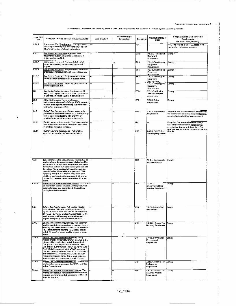
FPG3-ROS-C51 -0001 Rev.7 Attachment B
Attachment: B: Cormplianse and Trasahiitty Matrie of Units Level Requirements with EI'RI-TR1057330 and System Level Requirements
CrloITEM Vender Pachage ECONoESer Cemptiance with EPRI TR-107331fNO. M SUMMARYVOF EPRI TR-167330 REOUIREMUENTS 50RS Chapter 4 laformetlee Document SETOp~~ R rRequirements
(er N/A en Net Applicable)
6.22.1 CopomcessorTitAP Remdrenments. If ucoprocenson - - N/A -- N/A. TheToshiba NAW-FPSA based PAMsans a high-level language, then it shali have ite own systeto does nut use coprocessors.TSAP which implemrents the given laundoos.
6.2.3 Test aooortEouivmentgauuiremennt. Test - RtiS 7.3.I.3. Tevt Support Complyequipment to supporttAcceptacnceand Operability Equipmenttesting shall be provided. Requirements
62-3.A ITsat s ovotlinulorent. Equipmetnt salilnthlade ..-.. 60R 7.3.1.3. Testitopport Complypanals for connecting aed simulating onpals end Equipmentoulputs. Requiremeets
6.2.3.0 Test lutoovn Eculoment. Equipment shall inolude test -- - ERiS 7.2.1.3. Test Support Complyand measurmeant equipment wath mequfred accuracy. Equipment
resuirewevts62.,3.0 Tent Sunoort Foulorrent Equipment chall lnclude ..-.. RRS 7.3.1.3. Test Euppont Comply
=special tvolt cud devices ceeded to support testing. EquipmentRequirements
6.2-3.0 rest Sucovrt Eouiomevt. All test equipment shall ha -- -- ENS 7.3.1.3. Test Support Complycvoatrlled per IEEE 49B, Equipment
Requirements6.3 Oualffinution Tents cod Anvinos Raunheresten. Aln -- - alAS 7.3.2 Oualthaction Comply
testiog chatl be performed an a calibrated system wit Taste and Analysisall user setalnto values adjasted to default values. requinements
6.2.1 Anino Anuirmeetss. Testing shall lnclude - hS 7.32.1. Aging Complyenvuiromnental, alcucatosth duchaurge (ESD), ueismic, RequirementEMtI/RFI cod surge wtibstand testing. Environmenteltesting shall be pertouted thatt
6.3.2 siMIIRFI Test AR uirmoente. EMI/RFI testing to be - RhS 7.32?2. EMI/RRt Test Eaceptioe. Th EMI/RPI Test wan performed atpaeifored as described it SEclcon 4.3.7. Sasceptibitity Requiremeot the maximum oevals and the equipment passed.teals to be perlionmed alti25%, 5th/ cod 75% of so cc furter Ithreshald testivg was inquired.specified levela an addition te the specified levels.
6.32?1 iMIlAR Macnt~ne ARuitemente. Test specimen shall - /A -Excaption. Due Ia space limitatiens al Wylebe mounted one ecnon-neteilvi suratte sic teat abova Labs EMI/AFI chamnben, last specimen waestcoor with ne secondary ennceosur. mounted lass Ecun six feet shove floor. Test
•euemenvaes mnv~r mt ceec ,ncn vlrekrth-d,3.21 EMII FI Mountint Recuirements. PLC shall be - ERE 1.3.2.3. EMI/APR Test Comply
grounded per manuacuturer's recommendations. Mounting Requirement
6i.3.3 J vrtentol Testio Resuiremento. Tenting shall be -- - RS 7.324.4 Environmental Complypadeam~ed using the temper'ature cod relative humidity Test Requirementprotiae given in TR Figure 4-4. Margln shall he appliedto mealmom cud minimum specited rereperotouas endhumidtities. Power suorces shall be sat to masimizeheal disaipation. PLC shall be energizmd with TSAPupetating. Late-half Oi all disurelea, ed ede ayaotputoshall be on cud energized to reted current. All asalo gealputo shall be set ta cnn-halt to twoa-thirds fall scaleoutput.
6.3.2.1 Invironmental Test ounetirn Resulre-nents. PLO shtali - - RS 7.3.24.1. Complybe mouuvted un a simple structore. Air remspenatore of Saviroomental Testhanaom al chassis shall ha eraritored Na edditional Mouatieg Requirementceoling fanm shagl be Included.
6.3.4 SaismiuresftRsuimreents. PLCshallbenibration - ERS 7.3.25.tiSeismluTest Complyaged using tine OtiEs with the RAS as shame in TA AiequirmmentFigure 4-ti followed by an SEE with the RAE shown inTA Figune 4-ti. Testing shall cantons to IEEE 344. TO-ausal, rendcwn. muto-hrequensy taste shagl be used.Repairs dudng testing shall contarmn to IEEE 344.
6.3.4.1 7etsroTest Macutin Raaaienraet. Test specimen -- --. AS 17.3.2.51. SeisminTest Ccmnsplyshag be escJnted per maesaters rewemendatiorraiMoua'tieg RequlerneetMounting shvtore sthol hace en rimonaeces below 100Ha. Mest susceptihie mousntng canfiguradion shall betented. All mounting strains ohall be torqoad to kneown
ti.3,4.S 'teismolo Test Measurement Resairemento. Relay --- --AS 7.326.-6 Selnsmic Test Cumplycunteuts shall he monitored fon chatter. One hell of the Measuremeentrelays dhall be energiced and on half deencerglzecl. RequirementOne quarter of the relays shall transitiun from ON toOFF cod one quarter from OFF to ON Outing the teals.Tma PLC shall ha powered with gre TEAP operating.One hulaft oftihe digitol ustputs shall be Old cud loaded totheir rated currant Powuercsueroes shall be at lowervoltage and frequency limts, One or more responseaccelonrometerm shall ho macunted on each chassis.
ti.3A4.3 Seismin Test Performance Resuirements. Seinrolo test -- -ERS 7.3.26.1. Seismico Test Complyshall include a resanano racsearnh, live OB ita. ova 500 performencecud an Operability teal. Reqahrameat
6.3.4A4 Seisnmio Test Soeoo Analyss Resuiremmens. The --- EAS 7.32,62, Se~smnic Test Comeplytest resporae cpevnvm~ from the control and specimen Epectreir Analysisresponse ucueleromelero chad] he reported at 1/2, 1,2, Requirement3 cad 5% damping.
128/1 34
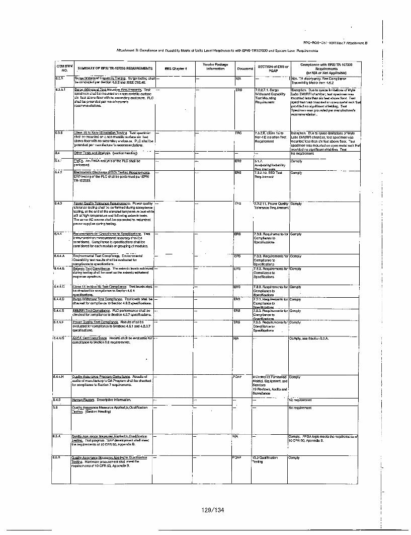
FPG-ROS-C51-StiDlRev.7 Attachment B
Attachment A: Compliance and Tracehility Matrix ci Units Level Requirements with EPRI-TR107330E and System Level Requirements
C7OE~tIE Vender Package SCINoESer Ceomplnce with EPRi TR-167330NO M SUMMARY OF EPRl TR-107330 REQUIREMENTS ENS Chapter 4 Informeation Dacament SETONfESo eqairemeents
(er N/A er Net Applicable)
6.3.5 Some Withstand Cexabilit Testing. Surge testing shall -- -r/A - I N/A. TA discripancy. See Compliancebe conducted per Secflon 4.6.2 and IEEE C62.45. Truceabiltity MatIxs Item 4.6.2
6.3.5.1 Surge Withstand Tent Mouantine Recuirements. Test --- ENS 7.3227.l. Surge Euception. Duselo spane Iiwltalions oiWyiespecimen shall he recanted onue on-mxetellltisurlace Witstand Capability tabs EMI/RFI chamber, test opectinon wancax test abonse floor with no secondany enulosune. PLO Test Macsting mournted less than cal test asove floo. Testshall be grounded per monutuacturer's Nequirement specimen wes moanted on open meta tech thereccmmendeflnstn prnoded ono significant shielding. Test
Specimen man grounded per mecufauanor'srecsxmnendaflon..
ti.3.e Gloss 1 Etc Non-iP latsotl•~n Testes. Test specimen - ENS 7.3.28. Cleans 16 te Eaceylion. Quoe tospace rtmitetiono of Wylechatl ho mounted ens• non-metallic scriace sal test 'Non-iS Isalutfon Test Lobs EMI/Rfi chambher, test specimen wanabove floor with no secondary escloscre. PLC shall be Aequirement mo0unted lean thus six feet abase gloor. Testgreunded per manufaauteret's recmommendations. speclmen wan mounted cc open metal rach the
•rosided no cigaoilcant shseldisa. Test6.4 Other Tests and Anuisi. (section heeding) -- -- - N requirement
6.4.1 EM2A. An FME-A analyisiscifthe PLC shall be -- ENS 5.1.7. ICompflypertormed. AoallabiiltyjRetiabllfly
6.42 _-lectreostaflc Dinshena ISiTsig Alsrerenta. --- ENS 7,3.2,10. ESO Test Comply-SEQ testing at the PLC shall be poerormred per EPRI Requirement
ITR-1 0323.
0.4.3 Power Osulit Tolerance AR airrenta. Power quL~ity -- - alS 7.3.211. Pwowr Cluelily Complyteleranue tecting ehall be pertormed during acceptance Tolerance Requirementtesting, at the end at the etecated temperatune test whilesoill at high terepenstur and flollowing seimenc lestsThe some AC source shall be connecte to redundantpower usupylios during testing.
6.4.4 9ecxdrements for Crnoianne to Snecilfcations. Test -- ENS 7.3.3. Requitemeote tar Complylnstxsunentation measurement eccurecy shall be Comptiance teconsidered. Comytiance te specifcatians shall ha Specificationsconsidered for each module or grouping at modales.
6.4.4.A Environmental Test Compliance. Enoiromnental - - ENS '.3.3. Rexluimements ton ComplyOperablily test results shall be evaluated tar Comnptiexice tecamplianue to specifications. -. Spealfications
6,.4A.B Seicric Test Cmo lisnce. The seismic locals achieced - - ENS 7'.3.3. Nequiremente for Complydadong testing shald beansed an the seisnral withstand Compliance: toresponse spectrue. . pecificaflons
6.4.4.C plain is toNan-isETest Coreeliance. Testtlevels shell -- - ENS 7,3.3. Ftequiremente for Complyhe cheched for oampfilancne toSection 4,6.4 Compllarwe tospecifications. .Specdficettons
6.4A.Q. Same Withstand Test Compltance. Test levels shell be -- - ENS 7.3.3. Aequirementa for Complychecked for compliance te Section 4.6.2 specificetion~s. Compliance te
6.4.4,5 EMIIRFI Test Comn liance. PLC penfonoance shall On -- - ENS 7.3,3. Aequiremeentsofr Complycheched tar campliance ta Secflon 4.3.7 specfiucatmens. Compliance to
Sneegfm:firanrs6.4.4.F Power Ouatit Test Comnallanna. ResalE shallb ho - -- ENS 7.3,3. Nequhremecls tor Com~ply
avaluatod tar compliance te Sections 4.6.1 and 4.23.7 Compliance tospeothuations. Specricelions
6.4A4.G !ASQA Test Comtriasre. Resolts shodl be esaluated tar --. N/A -Compiy, see Section 5.2A.carnptianam te Section 5.6 requirements.
6A.4.4H flual" Assurance Poram Cornalienca. Nesflt at .- -POAP 6 Control ci Purchased Complyoudits at mecufactuner's Oh Program shall be cheched Mutea, •qu'pment, andfor complirnce te Section 7 reqalnomenta. Sernices
19 Reslems, Audits analSuruealtsce
6.4.5 Hulmec Fac•tos. Qesciptive tnformetaxo -- - - No requirement
6.5 3uality Assuranne Measures Aspfied In Ouatitication -- - - No requirementTesting. (Section Heeding)
6.5.A . Iate Assrure Measures Aglied to Quatificetion --- N/A - Cmply. FPEA lgig meets the reqalrements atTesting. Test program TSAA deoelnpment shall meet 15 CPR 5O. Appendal B.the requirements at 15 CPA1SO. Appendis S.
6.5i.B ClualitAssuraaue MeasurescAoclied ta Qalifcation --- PQdAP 13.3 Quaflificatian ComplyTes. e. Hxndmare precurementshadl meet the Testingrequirementa of 10 CPR S0, Apperdla B.
129/1 34

PPG-ROS-C51-O001Rev.7 Attachmyent B
Attachment B: Compliance and Trucahblity Mab:in of Units Level Requirements with EPRI-TRJ 07330 and System Level Requirements
CTht ITEM Vendor Package S flNaESor Comopliaecrlcewth EPRI TR-107330tN. SUMMARY OP EPRI TR-107330 REQUIREMENTS ENS Chapter 4 Intenonatfon Document RequirementsD o
(or NWA or Net Applicable)6.S.C Quality .Assurance Meoasres Aeplied to Ocalification -- PQ'AP 13.3 Oualietlcs, o Comply
Testng. Test spachoan chain of custody ohull meet She Testingrequirementa etiti CFR 50, Appendlo B.
6.5.D Quality.Assurasce Meascres Acplied to Ouaiificuicon POAP 13.3 Qjualification ComlyTanhy. Taste and date analysis shall meet the Testingrequiremente at 10 CER 50, Appeodix B.
1 Quality Assurance. Descriptive ltnnarmalon. -- - - -- Nio requirement
7.1 Q3A Overview. Descriptive Infoemation. ...... - Nie requirement
7.2 I:O CPR SO tiendirt B Reslreonente tar Surtye - -- I- - ro requirement
Reae ytm. Descripive informautien.
7.2.A 110 CFR 50-Aelicablilv . Regultiurns apply to all 4.3.2 Safetypfeatsres - RS e.G. Clausitfication Complyqualification aunvtisfen. 1.
10.
0.0. Design Method ComplI6. Publication ComplyRequirements
1.2.B r0C~fFlISAnelicahility. Regulationsaupplyfo -- POAP 0.1 Software Control Complyepplicatisn specife antiaties. 13.2 Syst em Integration
Testing
12.C sO CPR 50 Annllcabilite. Regula.tions apply So PLC --- POAP 6.3 Commercial Sr-ude Complydedicetiun autivlties. Dedication
0 Central of PurchasedMaterial. Equipmentand Services
7.2.D 1f CFR 50 Comp liance. Quality procenses uther than - pOAP 9 Canneol of Purchased Comply101 CEE SD shall be shown te bo commensurate with 10 M aterial, Equipm entCR1 50. and Services
7.2.0 10CRQ 0omgianes~. Uualflter shafl perftennauciro -- POAP t19Resie/s.s Audits an'd Complyte contirmr rear manutucturersn qualty process has hueen Survailaeupplied te the PLC praduct.
72.F t0l Cap SO Cormellunca. Astute perforsed agalnst - POAP 6.4 Crihfoal Digital Complym1anufacturer programs other dhan 10 Cap 50O shall Reniewdemonstrate that the program process is 9Control of Purchasedcomnmensurate with 10 CFR 50. Material,Eqolpment
and Services
7.2.G V&V rem Enaalubati OsaJlher shunana eaire thu 4.32?13 Safety Peatrson -ERS 0.3Softteare Complymlanufacture/s V&V program te the anteda, in Seeten Reqidrensents7.4.
7.2.H Q:)aaificatiun Ten Wityssnin. The qualifier shall hare -- -- POAP 103,3Cualification Cromplythe tight te witynes qualification tents. Testing
p.3 t1l Cap at Cornellauce Resuirerneete. Section lfste 10 -- -- POAP 16 Nennanfoimnieg C-omplyCap at complias~ce caquhrem ente of a utility mwld Materials. Parts orapplies the PLC in a safety-refated application. PLC Componenteimanufacturer shall sopport problem inputting and
P.4 i'edtlcatim:n aend V~lidaT~on Reeruiremants. Qualif~er 4.32-13 Safety Features - ERS h.3 Seftware Complyshall eanauate the moanufansurer's V&V process for Ptequinnennteeshftare, Pirmwame and softwa•re rodes against POETE-4.3.2usd IEEIE 1 012. The qualifier shall conlirm thefollowing basic requiremnente ame met: af theree is aV&VPlan far the PLC prodant. h) software denet opmeard shallhe dune is acenrdance with a life cycle approach (seeI EEEPDd 1074-tfffl), and c) thensoftwamereqsirementsdocument shall ho reviewabhle.
IS Manufacturer Duatiticativn Maintenance Throunhout -- --- o i requirementProduct UeCyl. (suction heading)
i'.5.1 Overview or Manutacturer Qan~fitcatisn MaintenanceThroschout Product Life Cycle. Denonipptiae information. Jo requireente
130/1 34
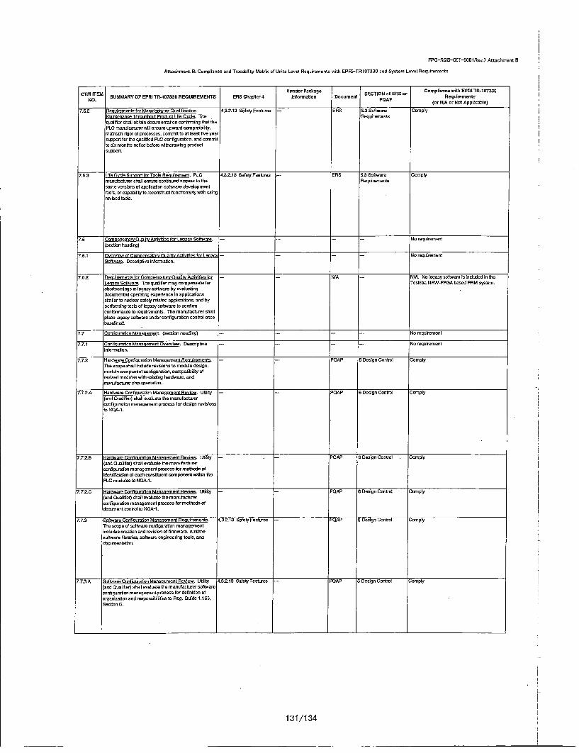
FPG-ROS-Cft1-001Reu.7 Attachment B
Attachment B: Compliance and Trocability Matrix of Union Level Requirements with EPRI-TRtiO7335 and System Lnuol Requirements
Vendr PakageCompliance with EPRI TR-107330CTM flTEM~ SUMMARYOFPEPRi TR-1S7330OREOUIREMfENTS BRS Chapter 4 toformoation Dnooment SECTnrN oorRS orpRluireme et
NO. PA
7.5.2 lecueimmento for Mauvfactsurer Cualifooiatin 4,3.2.13 Solely Features -- aRS 5.3 Software ComplyIfaintnarnce Thiruoehout Product Uife Cucle. The IReqoirernentsquelifior shall obtain dcouowentation contirmriog that toePLC marnuiaeterer will ensere upward crenpaithilily,mlaintain rigor of proceonno, commit te at leant fia year•upport tor te qeaitiled PLC configuration, end comemitto o months notice belowe withdrawing productsupport.
7.5.3 Lite Cycle SupportforrnTols Reatairreent. PLC 4.3.2.13 Safely Peaturos fiRS 5.3 Software Complymanofacturer ohall ensure continued access te the Reqoiremoentssome versions of application software developarenttools, or capability te recotnstact forntonatoy with usingrevised tools.
7.6 Cnooresatory Duality Arctiuities for Lenacn Softwsare. --.. ... No requiremennt(section heading)
7,6,1 tOvrniew of Ceorpenocthry Coaltty Activities for Lesacr -- -- No requirementSoftware. Descriptive informnation.
1.6.2 Recuirements for Comnensatory Onullity Activities for -N/ iA -NIA. No legacy software in included In theLeen otwr. The qualifier may compensate for Toohiba NRW-FPGA based PRM systero.ohortoomirgs in legacy software by evaluatingdocumented operating ecperience In applicationssimilar to nuoleeroeafely related applinations, and byperforming tents of legacy software to confinecoolformanne to requirenoento, The reanufactorer shallplace legacy software undarocontigoration control concebanclined.
/.7 Longi motion Manaeoment. (section heading) ---- -- No requiromeot
/7.71 ucnrihoration Meanaqmont Onermiew. Den.-liptive -.- -- No requiremoentIcernnation.
7.7.2 -aritwar Confieuration Mananoment Reequirenents. -- POAP 6 Design Control ComplyThe scope shall include revisions to module desIgn.noduinenomponent configuration, conmpatibllty ofreufoed mdodhoe withil isting hardware. andaranufactater docounentotion.
'o7.2,A Hardware Conflquretien Mananomen~t Review. Utility - PAP 6 Design Control Comply(and Coarlifier) shall nucleate the manufacturerconfiguration menagomoet process for design reelniowsto NOA-I.
7.7.2.6 Hardware Confleuration Meaneqennent Review. US - .ty PCAP 6 Design Control . Comnply(red Qualifier) shall evahuote the mnaufacturercerfigar-laon managesment process• for meothods ofidentifiratice of each anotioo cesporemtmwithin thePLC modulhs to NQA-1.
!7.7.2.C Hardware Confinoretirn Moanaemrentf Renew. Ufl~ty -- POAP 6 Design Contoot Crompty(end Doalifiet) shall enatoate the manulefactrerconyigoration maenagoment process for methods ofdoumetrnthontultofNOA-1.
7.7.3 Sftiware Conflocration Menecement Renuiremants. v,3.2-13 Safely Featores -PO'AP oDes~gn Contcui ComplyThe scope of software configuration managementincludes creation and revision of firmware. rontimesoftware libraries, software engineetdeg techs, anddecom'enltilon.
.7.73.A Software Confhouration Manacoment Rfeviow. Utility 4.3.2.13 Safety Peatores -POAP S DesIgn Control Comply(and Qualifier) shall evaluate the manufacturer software
configuration management process hor definition oforgenizton end renpensthllities to Req. Guide 1,16fi.Section C.
r.
131/1 34

PPG-R13S-C5l-fltOltfen.7 Attachment B
Attachment B: Compliance and Tracatiflity Matrix of: Unite Level Requirements with EPRI-TRi107330 and System Level Reguiremnente
CTM ITEM Vendor Package S tONoESor Compliance with EPRI TR9-107330NO. SUMMARY OF EPRI TR-1 07330 REQUIREMENTS ERS Chopter 4 tefoermatione Doosment PDAt' Requirements
(or N/A or Not Applicable)
7.7.3.0 Ne wrnOeoration Mananement Rnvinw. Ut/ilty 4.3.2.13 Safely Features -POAP 0 Design Conboel Comply(and Qualifier) shell evaluate the manutanturer softwareconfiguration management precess for methods ofcniguration Identification, canneol, statue and audIts tu
Reg. Guide 1.169, Section C.
7.7.3.C fetar efinuration Macno mecf Review. Ufilty 4.3.2.13 Sofety Features -- POAP 6 Design Control Comply(and Qualifier) obal evaluate the mecufauturertoefiguretuon management peoosss to oenure sub-Ocer,supplieos maintain comparable mobel of configurationmanagement par Rag. Guide 1.1609, Sectiun C.
7. Problem Reoertnelrckino Rcaeiremente. PLC - - POAP to Nonconforming Cramplymonufactarer uhall maintainsa problem reporting and Mutellals, Parts orteethIng system that includen claeelfication of problems. Componentsdesctiption of problems, identification of attestedhardware, typo of application. dancriptinon ofcontigurafion, came of reporting site and moans tocontact site, type of stite, and osmulatino operating limoof PLC whet problem occarred. Mocufocturer shallprovlde a meohunism tvt making thls lnfunnationancilattle te a/I nuclear atily users.
o Dvcurnentation. Dancdipt/vo information. -- -- - - No requirement
0.1 Nauiement Geteral Overmiew Document Renuiremoents -- -- - -- No requirementD esvdtipfve Intuonnafion.I
0.1.,A ManufavturerfDocumentatgon. Dnoumentationtehall -- '--RS9 9.1.1. Equipment Cumplyincludo o descriptiun ef the PLC. general overvewe
document
8.t .B Manufanturer Documontemioc. Documentaticn shall - - N/A -IN/A. Toehiba NRW-PPGA based PRM systeminclude a description of the cfhassis lnfteconneutno.• 'do cot sue multipita obauseeo. Instead, the
system conteins UntI intercanceutions,
O.1.C M•anufactremr Documentation, Documoentatone shall - - N./A -- N/A. utety dte not need tune/reft Toshibainuudo a module overvewoa and saloction guide. NRW-FPGA based PRM system modules.
O.1.D Mtsnufocturer Danumentatine. Dnonomnteionesbaf] --- ERS 0.1.1. Equipment ComplyInclude a description of the oveacal I/O capacity and ganaral ovetviewprocessing upeeds. document
0I.1. Manufacturer Documentation. Documentation shall .- - ERS 90.1.3. Usero Manual Complyinclude luetallatiun infennation.
0.1 ,F Manufantaer Dooumentation. Decumentatron shall -- - RS 9.1.1. Eqaipmeont Comply* inelude handlthqo and steraeo remulm/!erers, roneral overview
0.1 .G Manufacturer Docuentation t ooteanntatimn shall -- E19S 9.1.1. Equipment Complyinclud a description 0f the soft-,-ag nosvticsand general oveediewe~rO rnotnrv teen ne wc flf
0.2 aioltrent Goerat Soeciticatices Renlremeonts. --- ERS d.1.1. Equlpment ComplyManufactuemr docarveantetion shall preside genetad general overm/owupecificatinons for the PLC. document
0.3 Operatores Manual Requiremoents. Munutacturer ....-. ERS 9.1.3. Usero Manual Complydocumeontatione shall include informoation on oporaf/un of'ho Pl C
0.4 Prnoermmerms Manual Recqdrana'ents. Manufauturer -- -- rN/A -- N/A. Toshibadoesnoct provide the utility wit, astall providc detadoed infonmagion on the use of the Programmer's Manual of the NRW-PPGAtunct/ues avaiteble vi the PLC prooeesors, based PPM system.
0.ti 'eulomont Matirancc Mannal Ronienrnt. -- - EPO 9.1.3. Users Manuel ComplyManufantuemr dnceoenntation shall cmta1in ortumationfur calibration, frouble shooting. mahrenr ,o reqshedspecuad tonic or software, and crroan~icatico protet.Movnutacturer documentation shall indtude remults ofcrompanent aging anciysin.
0.6 "tuaiticamion Cocranentation Rocirements. (Seotiun .-- - No requnrmoentHeading)
0.0.1 0
racm agc Docomeetafion ueniremeonts. - - - Na requirementDoom/pt/sn infonnatior.
0.6,1 .A P ramermaflo Docem'enrtiuro. A test p/on shall be ---RtiS 9.3.1 Programmotic Complyprepared which includes test plans fur environmental, Documentationseismic, surge, Class 1 ft to Non-1fE, EMI/P F'. Requirementsavailab/flty/reiallabl y, FMEA and ASDA qualification A.activites.
132/1 34
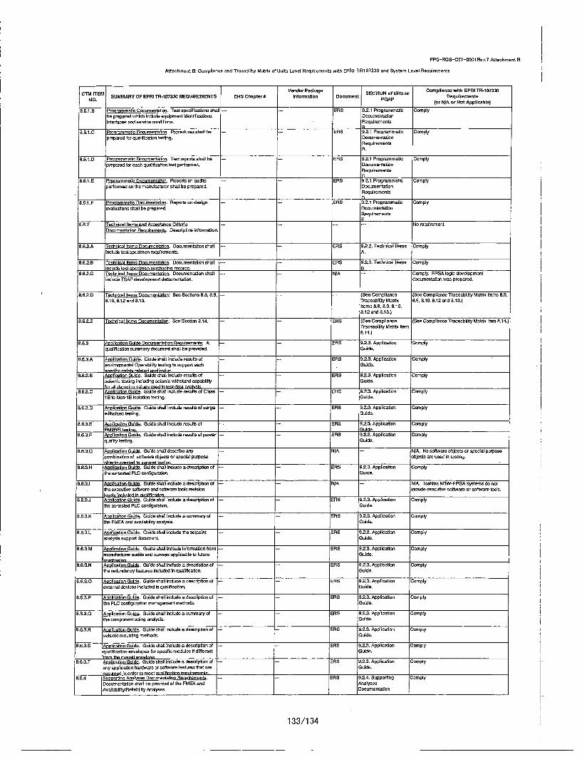
FPG-ROS-Cft-Si-060Rev.? Attachment B
Attachment B: Compliance and Trucability Matria of Unito Level Requirements with EPPRI-TR107330 and System Level Requirements
~ TMVeedor Package SCONoESor Comopllence with EPRI TR-1907330NTM ITM SUMMARY OF E]PRI TB-i 0733 REQUIREMENTS PBS Chapter 4 Informatioe Docement SCONoES rReqoirements
(or N/A or Not Applicable)
0.6.1 .B Prsamratio Documentation. Test specifications shall -- - P=RO 9.2.1 Programmatic Complyhe prepared which include equipment identifications, Documentationinterfaces cand cornice coeiliuons. .Requirernents
8,6.1 .C PrnqrammaticioDocaumentigon. Procedoursshall be -- -- ENS 9.2. 1 progroammatio Complyprepuord for qualifcation testng. ocaumentotion
RequiremeentsB.
g.6.1.D Prourammolin Cocumontatine. Test reports skull be -- ENS 9.2.1 Programmatic Complyprepared for neack qoalihoaic•n test pertorcmedt. CDomentation
Requirements
8.8.1 .0 P rermmatic Documeetotion. Roports on audhots ERS g.2.1 Programmatic Complyperformed en tire manutocturer chatl be prepared. Duconmentationt
Requirements
.6.1tF Procm ot tcumonltiaon. Rleports on design i- - ERS n.2.i programmatic Complyevaluations skull be prepared. Dnoumenteotion
Requirements
8.6.2 'ecknical Items cad Acceptance Cditeriua- - -- -- No requiremeontCeoumentation Resoir eaels. Cosodptiae infornnaliec.
6.62.A Technical itows Cecureentotien. Cocareesaticeo skull --- NRS h.2.2. Technical Items Complyirclude test specimen requireements. IA.
8.8.2.8 Tecknlcal Items Deomentation. Danomentatiun skull --- ERtiS 9.2.2. Technical Items Comrplyinclatic test specimen eourchaulenq recortis. ___________
8.6.2.C Technrical trees Documeetatione. Cocumentsutin skull --- N/A -- Comply. PPGA login devetopreentenlude TOAP development dooenetation. documeetatiec woo prepared.
6.682. Technical lows Deomentation: See Sections 9.8.89.9. .---- (Sea Complicatce (Sec Complicatce Traceabiulity Muldo Items 8.8,0.10. 8.12 cad 8.13. Troceub itity Moolof 8.9. 8.10. Si2cand 8.13.)
Itown 8.8, 8..9 8.10.8.12 and 8.13.)
0.6.2.0 Tecknical lows CGocureetatine. Sec Section 8.14, -- --. ES (See Cetmp~liece (Sec Complcanca Traceability Matrix Item 8+14.)Traceability Metrix Item6.14.)
8,6.3 ADHol nto Guide Domcorentution Recuiremeste. A -- -- PRO 9.2.3.3 Application Complyqualification seminary deaumnont skull be provided. Guide,
8.6.3.A Anolic~akoc Guide. Guide shut include toothts of -- -- ENS 9.22. Apphicatiun C.omplyenoireomcental Operahiiity touting to coppert each Guide.sodTflr soloN related aen~lireine
8.8.3,8 AclntceGlo Guide shah bnlade results of -- -- ENS 0.2.3. Application ,Complyseismics testing Incuding seiranic weitihstund capability Guide.
enrl1 dormnin losvt e mcd*' in tos.t ,dotr' onenniwo8.63.C wolcto Guide. Guido shall include results of Clarm I - -- ENS n2.3. Afpplication Comply
tE ts Nun-i P isolation testing. Guide.
8+6.3.C renolication Guide. Guide shall irnohda reset of sorge -- -- ERS 9.2.3. Application Complywithstood tooting. Guide.
8.8.3.6 liaie od. Guide shall include reut of -- fiRS 9.2.3. Application Comply-MIIRN festive. ," uide.
8.6.3.P Anlai ud. Guide shall include result of pomer -- -- PRO 9.2.3. Appfication Complyquality testing. Guide.
8.6.3.G _Aponcaticn Guide. Guido shahl descriha any -- -- N/A -- h/A. No sotftwure objects on special purposecombination of software nbobjeto crupeclul porpesa objects ame used In tooting.rhiocts emnated to sunnort renti rm
8.6.3.H Aclnta ud. Guide shal lesiede a desciptieon o -- -- PRO 8.2.3. Application Complytire es-tested PLC canFhgurotica. Guide.
&8.6.3 .__AcohoeaionGuide. Guide shutloinde a descrptonaof -- - N/A -- NIX. Toshiba NRW-FPGA systemsdoenottoe excoutise soutwatoreant su•twaem thou 'revision include esecutice software or softwreat tools.I___ .v_ erm inetledd In rndraifirutinn
8.8.3.J Apsfication Guide. GuIde shall include a description of --- PRO 8.2.3. Application Comptythe us-tooted PLC canfigomaton G•uide.
8.6.3.K Apptuahaon Guide. Guidie shall include a seminary of --- ENS 9.2.3. Application Complytoe PFMA cand anailability analysis. Guide.
8.8.3.L Afiplication Guido. Guide ohall incduda thu surpuint -- E RO 9.2.3, Apphccadon Complyanalysis support daceent. ,Guide.
B,6,3.M Anonc~tion Guide. Guide shall inobede intormatioe (romn- - ENS 9.2.3. Application Comply,nuanuoae-er audIts and surveys applicabte to future Golda.
8.P.3.N Appticatiec Guide. Guide shall iredade a descriptionl of -- --. NS 9.2-3. Appliceatio ComrplyThe redundancy teuturms included is qualification. Golda.
8.6.3.0 Anlcto od. Golda skull include a description at -- -- RS 8.2.3. Application Complyextemnal devcoes included In quatifiation. Guide.
8.ti.3.P Antcto ud. Guide chel] brnlude a descrdption of -- -- h-.S 0.2.3. Application Complytoe PLC configuration munugecent methods. Golda.
8.fi.3.Q Achoisod. Suideashall includooecasmutayuof -- -. PRO 9.23.2Appiicaticn ComplyThe camponeot aging anabysis. Golda.
e.6.3.R molctonGtl. Guide chatl include a dencription of -- -- EN5S 9.2.3. Apylicahion Complyseismic mounting mathodo. Guide.
fl8.3.+S AnOtilcahon Guide. Guide shall tincludo a description at -- -- ENJS 92?3. Applica.tion Complyqualofcation envelopesoor spnecificnomeduoidsifdffoemnt Guside.'rem the nwerei enueinre
8.8.3.T Gonlication Guide. Guide shalt atolode a description at -- -- -ENS 9.2.3. Application Complyan~y application hardware orsoftteare features toataem Suide.vs. reed in rdnt ner eset ntrei[roation rentuiremoenf __________
8.6.4 fu notto Anules Gecanreototion Reouirements. -- -- RS 9.2.4. Supporting ComplyDcumenototion shall ko provided of toe PMEA and AnalysesAnvtuhiaihty/fletollatity Analyses. Cocumnentetion
133/1 34

FPG-RDS-CSI-000l Rev.? Attuchmeent B
Attochmeet B: Compliance and Travabilicy, Metris of Colts Level Requirements with EPRI-TR1il07330 and System Level Requiretments
Vendr PakageCompliance wIth EPRI Tfl-107330CTM ITEM VeMR FER R173 EQIEET R hpe nderrnPackage cuen SECTION of ERS or Rqieet
NO. PASUMMRY P ERI R-1733 REQIREENT ER Chpte 4 Iforat~n Dcumnt OAP(or NWA or Not Applicable)
8.6.5 Clasn IE to Non-IS Isolation Test Plan. A Class1E ta -- - RS 9.21. Prgrarnmaftc ComplyNon-Ilf Isolation test plan and report shall ho provided. Dsocmeotation.yetnt e~lann shall he rvilewed and onnmn o ho Iho
8.7 V/&V Documeetation Reaoitmeonta. Dasotip]vo -- -- - No requirement
8.7.A V'&V Dsocunentotlon. Documenfti~on shalt inolode 5 -- -- PAP 6.1 Software Control Complysoftware quality aossurance ylen.
8.7.B =V&V Ososlmentation. Daounrestafion shall inolude a -- -RS 9.2.S. V&V Compylysoftwate requiremenots specitication. socumentation
A.
8.7.C V&V Doocteentah~on. Domentution shall includes a - -- ENS 8.2.5. V&V Complysoftware design desotlytion. Docuentartuion
8.6.7.D V&V Documentation. Dnoumentabton shalllinclude a -- -- tiRS fotee Compliance ISea Compliance Traceability Matrix Items7A.)
software V&V plan. Tracability MotrixItemns 7.4.)
5.7.E V&V Documentation. Dnoumentation shall Incldo a, t.3.2.t3 Safety Features -ENS 8.25. V&V Complyso ftwa VVre por wytt Dacumentation
8.7.F VEM Doosmentation. Doctenentetion shall include ..... (See Complianca (See Compliance Traceability Mutria Items 8.3)software user ducumentation. Truceshbifiy Matixs
Items 8.3)
8.7.0 V&M Docornentation. Dsoranestation shall incude a -- FDAP 6.1 Solhware Complysoftware nonfiqunction management plen. Rensiremeonts
0.8 Stiesre Desca"nhlon Reaimmeol. A test specimen -- -- tiRS 9.26. TestSystem Comply
hardware sod software desotiption document shall be Desotiptionprovided.
8.8 fdtitial Characteristics LUstinoResirenteni A otitical -- -- ERS 9.2.7. CdftnaJ Complyobharactetistire Imistig document shall be provided. Chanacteristics
0.10 sstem Crawlno Reotimemes'ts. (Section Needing) -- - -- - No requireents.
o.10.A Sestem Crawlno Renuirementa. Drawings shall irchuda-- -- EFNS 9.26. Test System Complyal functonel dencdiption of the test spedimen. Drawing 4.
8.10.6 SystemDrawin Renuirornents. Drawings shall include - -- El -R .2.8. Test System Complya sohematic ofth taent specimen. Crowing A.
8.1lD.C Sstem Drewir Resuirmentn. Drawings sha~llinclude-- -- NM - Comply.dIagrams Stat define toe TSAP.
0.10.0 Syse Drowien Reulremenfs. Dramings shall shom -- -. RS 9.28. Test System Camplytest specimen wiring, psawer dls-ttitiufln and grecudtng. Drawing A.
6.10.8 Susem Drawie uaniterents. Drawingsshaf show --- ERS 9.28. Test System Complylaysut of test spedimen chassis. modules end Drawing B.
'8.1S.F Sfem Drawien Resuireenwst. Drawings shall show -- -EifS 9.28. Test System Complytest specimen mnounftng and mowartng fixufres DrawIng C.ledrdg special installtion reqtirenen ts.
8.11 'vroSefhwaresaada C "forle Docawrnlt -- ERS 9)2.9. System CromplyRerdreens Software and hardiware ononigoration Softwonr/Hatdwareusand for qua~fication testing shraJt be doraunesfed. Contiguronindaiung identiftcaoon and revision of executne socumestsoftware, modsle Stnewaere so ftware tools,downbsodable PLC executive packages, and Ste TSAP(indouding printout). The Identiftnafon. revisiot leveland seodal number of hardmaem shall be documnented.
8.12 'lse Database Documentation Renuiremeents. The ~- -- NIA - NA. The PRM system does notouse aTSAP?T/SP? database aced for qualifioation testing shsfll be tahebse.documented.
8.13 Syt11em So Calibrairl em becoot Fe dr -- -- ERS. 9.210. System ComplyR iromeris All setup. setha~btio andl shebeout etoplCahhbratrtCbec
proodures aced during qseatflceltin sledho heost Pruedadocumented.
8.14 System Test Documentation Rlenuirements. A test plan --- ERS 9.2.11. System Test Complyend test repent shall ha provided rovering qualiftuation D)ocumentationOperability testing. The documenets shell include testrequinementa. auceptance critetia, sequence of testing,date. recording meteods, lest equipment tequiremeotsand a test data summary.
8.15 fanafeafcrens Duolir Documentation Resalermeena.-.P-rAP 9.Ccentmi of Purmhased ComplyThe manufacbtuer shall provide Its Duality tissuranue Material. Etquipment,Ples, and Services
8.16 Manofacturern Certifiratons Resimns POAP g.Cono'ol at Purmhaued ComplyMacofacturer shall previda certftoates ot contoemnoce Material. Equipment.for all test specbnen hardware. acd Sewvices
134/1 34

![PSNN-2014-0869I US Safety-Related · 2015-09-28 · PSNN-2014-0869I US Safety-Related] [Document No. j FPG-PLN-C51-0002 7 Rev 2 rhe use of the information contained in this document](https://static.documents.pub/doc/80x56/5e692c8f9bd5e10e6c0b3383/psnn-2014-0869i-us-safety-related-2015-09-28-psnn-2014-0869i-us-safety-related.jpg)


