advanced encryption standard was accepted as a Federal Information Processing Standard (FIPS) standard. In order to reduce the area consumption and to increase the speed mix and inverse mix column transformation can be used as a single module .This paper contains design of new architecture, its simulation and implementation results and comparison with previous architecture.
4
IJSRD - International Journal for Scientific Research & Development| Vol. 1, Issue 9, 2013 | ISSN (online): 2321-0613 All rights reserved by www.ijsrd.com 1981 FPGA Implementation of Mix and Inverse Mix Column for AES Algorithm Neethan Elizabeth Abraham 1 Tibin Thomas 2 1 Dept. of Electronics and Communication Engg. 2 Dept of Computer Science & Engg. 1, 2 Federal Institute of Science and Technology (FISAT), Angamaly, India Abstract—advanced encryption standard was accepted as a Federal Information Processing Standard (FIPS) standard. In order to reduce the area consumption and to increase the speed mix and inverse mix column transformation can be used as a single module .This paper contains design of new architecture, its simulation and implementation results and comparison with previous architecture. Key words: mix column, inverse mix column I. INTRODUCTION The rapidly growing Internet and wireless communication users has led to increasing demand for security measures and devices to protect user data transmitted over channels. Two types of cryptographic systems have been developed for that purpose: symmetric (secret key) and asymmetric (public key) cryptosystems. Symmetric cryptography, such as in the Data Encryption Standard (DES), and Advanced Encryption Standard (AES) uses an identical key for the sender and receiver, for encryption and decryption. Asymmetric cryptography, such as in the Rivest-Shamir- Adleman (RSA) and Elliptic Curve algorithms, uses different keys for encryption and decryption. Symmetric cryptography is best suitable for the encryption of a large amount of data. The AES algorithm defined by the National Institute of Standards and Technology (NIST) of the United States has been widely accepted to replace DES as the new symmetric encryption algorithm. AES encryption is an efficient scheme for both hardware and software implementation. Much work has been presented on hardware implementations of AES using field programmable gate arrays (FPGAs) [2–5], and comprehensive analyses of the performance of the AES finalists was presented based on FPGA implementations, before Rijndael was selected as the AES algorithm. II. THE AES ALGORITHM The AES algorithm is a symmetric block cipher that processes data blocks of 128 bits using a cipher key of length 128, 192, or 256 bits. Each data block consists of a 4 × 4 array of bytes called the state, on which the basic operations of the AES algorithm are performed. After an initial round key addition, a round function consisting of four different transformations — SubBytes(), ShiftRows(), MixColumns(), and AddRoundKey() — is applied to the data block (i.e., the state array). The round function is performed iteratively 10, 12, or 14 times, depending on the key length. During last round MixColumns() is not applied. The four transformations are described briefly as follows: 1) SubBytes(): it is a nonlinear byte substitution that operates independently on each byte of the state using a substitution table (the SBox) 2) ShiftRows():it is a circular shifting operation on the rows of the state with different numbers of bytes (offsets) 3) MixColumns(): it is the operation that mixes the bytes in each column by the multiplication of the state with a fixed polynomial modulo x 4 + 1 4) AddRoundKey(): it is an XOR operation that adds a round key to the state in each iteration, where the round keys are generated during the key expansion phase. The decryption procedure of the AES is normally the inverse of each transformation (InvSub-Bytes, InvShiftRows, InvMixColumns, and AddRoundKey) in reverse order. However, the order of InvSubBytes() and InvShiftRows is indifferent. The decryption procedure has to be rearranged as, where the InvRoundKey is obtained by applying InvMixColumns() to the respective original Round Key. Such a structural similarity in both the encryption and decryption procedures makes hardware implementation easier. III. MIX AND INVERSE MIX COLUMN TRANSFORMATION The Mix column transformation performs a linear operation on the columns of the state matrix. It operates on the columns of the state matrix i.e., 32 bits. It causes every byte in a column to affect every other byte. The state matrix is represented as column polynomials over GF (2 8 ) and the transformation consists of matrix multiplication of the state with a polynomial over a finite field. The mix column transformation step is the only place in Rijndael’s round transformation where the columns are mixed. This step works with the Shift Row step to ensure that all parts of the block affect each other. For a data block of 128 bits, the state matrix has 4 rows. Therefore, the columns of the state matrix are each viewed as the polynomial of degree 8 over GF (2 8 ). The forward mix column transformation, called MixColumns, operates on each column individually. Each byte of a column is mapped into a new value that is a function of all four bytes in that column. The transformation can be defined by the following matrix multiplication on State. The MixColumns transformation operates on the State column-by-column, treating each column as a four-term polynomial. The columns are considered as polynomials over GF (2 8 ) and multiplied modulo x4 + 1 with a fixed polynomial a(x), given by C(x) = (03x 3 +01x 2 +01x+02) moduli x 4 +1 The coefficients of the fixed polynomial are in hexadecimal and are the elements of GF (2 8 ).The Mix Column transformation for encryption and decryption is represented as in Figures 1, 2 respectively. This can be
Transcript
IJSRD - International Journal for Scientific Research & Development| Vol. 1, Issue 9, 2013 | ISSN (online): 2321-0613
All rights reserved by www.ijsrd.com 1981
FPGA Implementation of Mix and Inverse Mix Column for AES Algorithm
Neethan Elizabeth Abraham1 Tibin Thomas2
1Dept. of Electronics and Communication Engg.
2Dept of Computer Science & Engg.
1, 2Federal Institute of Science and Technology (FISAT), Angamaly, India
Abstract—advanced encryption standard was accepted as a
Federal Information Processing Standard (FIPS) standard. In
order to reduce the area consumption and to increase the
speed mix and inverse mix column transformation can be
used as a single module .This paper contains design of new
architecture, its simulation and implementation results and
comparison with previous architecture.
Key words: mix column, inverse mix column
I. INTRODUCTION
The rapidly growing Internet and wireless communication
users has led to increasing demand for security measures
and devices to protect user data transmitted over channels.
Two types of cryptographic systems have been developed
for that purpose: symmetric (secret key) and asymmetric
(public key) cryptosystems. Symmetric cryptography, such
as in the Data Encryption Standard (DES), and Advanced
Encryption Standard (AES) uses an identical key for the
sender and receiver, for encryption and decryption.
Asymmetric cryptography, such as in the Rivest-Shamir-
Adleman (RSA) and Elliptic Curve algorithms, uses
different keys for encryption and decryption. Symmetric
cryptography is best suitable for the encryption of a large
amount of data. The AES algorithm defined by the National
Institute of Standards and Technology (NIST) of the United
States has been widely accepted to replace DES as the new
symmetric encryption algorithm. AES encryption is an
efficient scheme for both hardware and software
implementation. Much work has been presented on
hardware implementations of AES using field
programmable gate arrays (FPGAs) [2–5], and
comprehensive analyses of the performance of the AES
finalists was presented based on FPGA implementations,
before Rijndael was selected as the AES algorithm.
II. THE AES ALGORITHM
The AES algorithm is a symmetric block cipher that
processes data blocks of 128 bits using a cipher key of
length 128, 192, or 256 bits. Each data block consists of a 4
× 4 array of bytes called the state, on which the basic
operations of the AES algorithm are performed. After an
initial round key addition, a round function consisting of
four different transformations — SubBytes(), ShiftRows(),
MixColumns(), and AddRoundKey() — is applied to the data
block (i.e., the state array). The round function is performed
iteratively 10, 12, or 14 times, depending on the key length.
During last round MixColumns() is not applied. The four
transformations are described briefly as follows:
1) SubBytes(): it is a nonlinear byte substitution that
operates independently on each byte of the state using
a substitution table (the SBox)
2) ShiftRows():it is a circular shifting operation on the
rows of the state with different numbers of bytes
(offsets)
3) MixColumns(): it is the operation that mixes the bytes
in each column by the multiplication of the state with a
fixed polynomial modulo x4 + 1
4) AddRoundKey(): it is an XOR operation that adds a
round key to the state in each iteration, where the
round keys are generated during the key expansion
phase.
The decryption procedure of the AES is normally
the inverse of each transformation (InvSub-Bytes,
InvShiftRows, InvMixColumns, and AddRoundKey) in
reverse order. However, the order of InvSubBytes() and
InvShiftRows is indifferent. The decryption procedure has
to be rearranged as, where the InvRoundKey is obtained by
applying InvMixColumns() to the respective original Round
Key. Such a structural similarity in both the encryption and
decryption procedures makes hardware implementation
easier.
III. MIX AND INVERSE MIX COLUMN
TRANSFORMATION
The Mix column transformation performs a linear operation
on the columns of the state matrix. It operates on the
columns of the state matrix i.e., 32 bits. It causes every byte
in a column to affect every other byte. The state matrix is
represented as column polynomials over GF (28) and the
transformation consists of matrix multiplication of the state
with a polynomial over a finite field. The mix column
transformation step is the only place in Rijndael’s round
transformation where the columns are mixed. This step
works with the Shift Row step to ensure that all parts of the
block affect each other. For a data block of 128 bits, the
state matrix has 4 rows. Therefore, the columns of the state
matrix are each viewed as the polynomial of degree 8 over
GF (28).
The forward mix column transformation, called
MixColumns, operates on each column individually. Each
byte of a column is mapped into a new value that is a
function of all four bytes in that column. The transformation
can be defined by the following matrix multiplication on
State. The MixColumns transformation operates on the State
column-by-column, treating each column as a four-term
polynomial. The columns are considered as polynomials
over GF (28) and multiplied modulo x4 + 1 with a fixed
polynomial a(x), given by
C(x) = (03x3+01x
2+01x+02) moduli x
4+1
The coefficients of the fixed polynomial are in
hexadecimal and are the elements of GF (28).The Mix
Column transformation for encryption and decryption is
represented as in Figures 1, 2 respectively. This can be
FPGA Implementation of Mix and Inverse Mix Column for AES Algorithm
(IJSRD/Vol. 1/Issue 9/2013/0071)
All rights reserved by www.ijsrd.com 1982
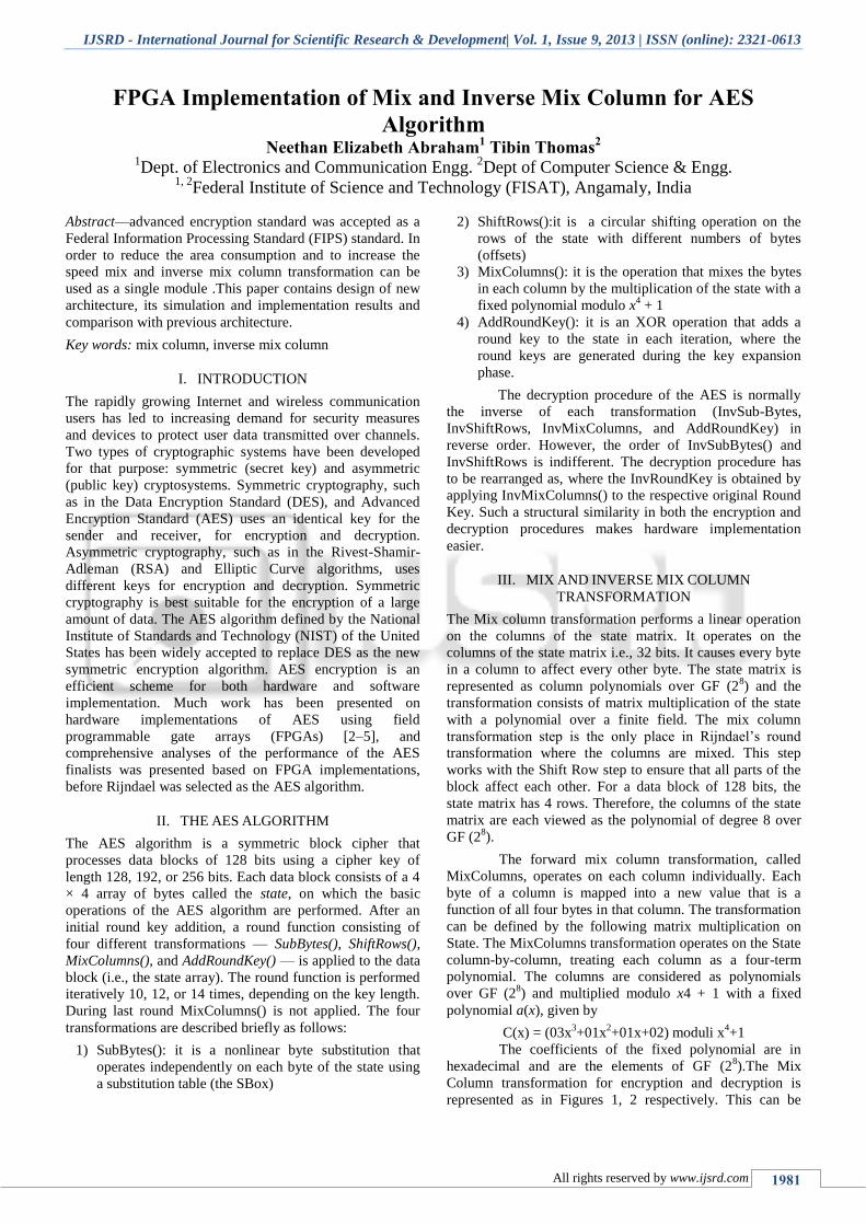
represented in algebraic form as a matrix multiplication. Let
B(x) = C(x) *A(x).
[
] [
] [
]
The multiplication of a fixed polynomial over GF
(28) is calculated using shifts and exclusive OR operations.
The resulting equations for each byte in the column are as
follows
( ) ( )
( ) ( )
( ) ( )
( ) ( )
Fig. 1: Mix Column Transformation for Encryption
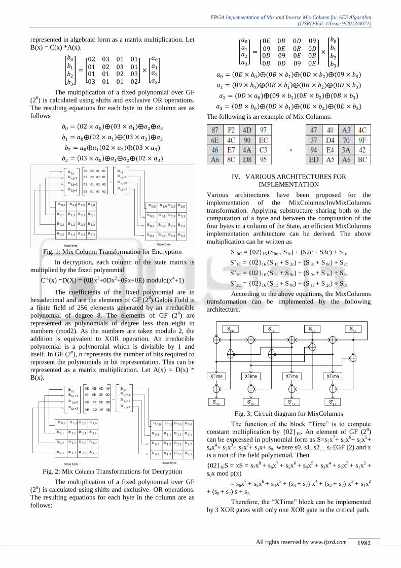
In decryption, each column of the state matrix is
multiplied by the fixed polynomial
C-1
(x) =D(X) = (0Bx3+0Dx
2+09x+0E) modulo(x
4+1)
The coefficients of the fixed polynomial are in
hexadecimal and are the elements of GF (28).Galois Field is
a finite field of 256 elements generated by an irreducible
polynomial of degree 8. The elements of GF (28) are
represented as polynomials of degree less than eight in
numbers (mod2). As the numbers are taken modulo 2, the
addition is equivalent to XOR operation. An irreducible
polynomial is a polynomial which is divisible by 1 and
itself. In GF (2n), n represents the number of bits required to
represent the polynomials in bit representation. This can be
represented as a matrix multiplication. Let A(x) = D(x) *
B(x).
Fig. 2: Mix Column Transformations for Decryption
The multiplication of a fixed polynomial over GF
(28) is calculated using shifts and exclusive- OR operations.
The resulting equations for each byte in the column are as
follows:
[
] [
] [
]
( ) ( ) ( ) ( )
( ) ( ) ( ) ( )
( ) ( )( ) ( )
( ) ( ) ( ) ( )
The following is an example of Mix Columns:
IV. VARIOUS ARCHITECTURES FOR
IMPLEMENTATION
Various architectures have been proposed for the
implementation of the MixColumns/InvMixColumns
transformation. Applying substructure sharing both to the
computation of a byte and between the computation of the
four bytes in a column of the State, an efficient MixColumns
implementation architecture can be derived. The above
multiplication can be written as
S’0C = {02}16 (S0c + S1c) + (S2c + S3c) + S1c
S’1C = {02}16 (S 1c + S 2c) + (S 3c + S 0c) + S2c
S’2C = {02}16 (S 2c + S 3c) + (S 0c + S 1c) + S3c
S’3C = {02}16 (S 3c + S 0c) + (S 1c + S 2c) + S0c
According to the above equations, the MixColumns
transformation can be implemented by the following
architecture.
Fig. 3: Circuit diagram for MixColumns
The function of the block “Time” is to compute
constant multiplication by {02}16. An element of GF (28)
can be expressed in polynomial form as S=s7x7+ s6x
6+ s5x
5+
s4x4+ s3x
3+ s2x
2+ s1x+ s0, where s0, s1, s2…. s7 £GF (2) and x
is a root of the field polynomial. Then
{02}16S = xS = s7x8
+ s6x7
+ s5x6
+ s4x5
+ s3x4
+ s2x3
+ s1x2
+
s0x mod p(x)
= s6x7
+ s5x6
+ s4x5
+ (s3 + s7) x4
+ (s2 + s7) x3
+ s1x2
+ (s0 + s7) s + s7.
Therefore, the “XTime” block can be implemented
by 3 XOR gates with only one XOR gate in the critical path.
FPGA Implementation of Mix and Inverse Mix Column for AES Algorithm