17
| Date post: | 21-May-2018 |
| Category: |
Documents |
| Upload: | truongcong |
| View: | 241 times |
| Download: | 1 times |

NanoCAD Lab
Outline
• Overview of FPGA
• FPGA Architecture
• FPGA CAD Flow
• Clustering and Placement
– Simulated Annealing-based method
• Physical Synthesis Optimization
• Routing
2

NanoCAD Lab
FPGA Overview
• Field-Programmable Gate Arrays
– Pre-fabricated silicon devices that comprise of an array of
uncommitted circuit elements (logic blocks) and
interconnect resources
– An IC designed to be configured by end-user after
manufacturing
• Implement any logical function that ASIC can perform
• Applications:
– DSP
– Device controllers
– Medical imaging
3
NanoCAD Lab
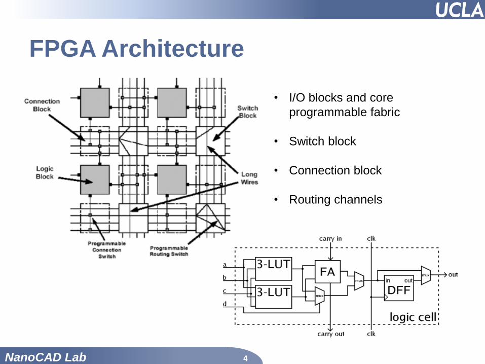
FPGA Architecture
4
• I/O blocks and core
programmable fabric
• Switch block
• Connection block
• Routing channels
NanoCAD Lab
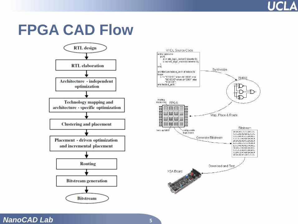
FPGA CAD Flow
5

NanoCAD Lab
Clustering
• Group logic elements into logic blocks
• Separate clustering step may be performed
prior to placement
• Reduce the number of logic blocks to be
placed
• Simplify legality checking for main placement
• Algorithm: greedily packs LE with the highest
attraction to the current cluster
6

NanoCAD Lab
Placement
• Slot assignment problem
• Placement has significant impact on the
performance and routability of circuit design
• Existing approaches to FPGA placement:
1. Simulated Annealing-based placement
2. Partitioning-based placement
3. Analytical method-based placement
7

NanoCAD Lab
Simulated Annealing-based Placement
• Placement optimization engine for placement used
in the well-known VPR package for FPGA
8
NanoCAD Lab
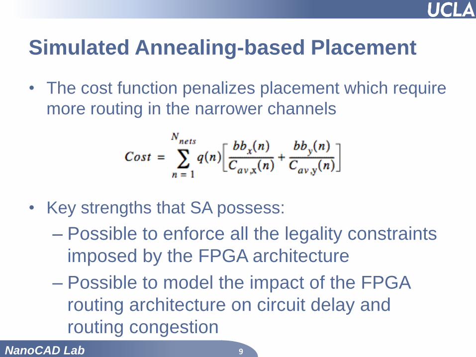
Simulated Annealing-based Placement
• The cost function penalizes placement which require
more routing in the narrower channels
• Key strengths that SA possess:
– Possible to enforce all the legality constraints
imposed by the FPGA architecture
– Possible to model the impact of the FPGA
routing architecture on circuit delay and
routing congestion 9

NanoCAD Lab
Physical Synthesis Optimizations
10

NanoCAD Lab
Routing
• FPGA routing consists of pre-fabricated metal wires
and programmable switches
• Interconnect between wire and CLB I/O blocks
• FPGA routing typically goes through:
– Routing-resource graph generation
– Global routing
– Detailed routing
• Two-Step Routing
• Single-Step Routers
11

NanoCAD Lab
Routing-resource graph
• An abstract data representation for global and
detailed routers
• Vertices: I/O pins of logic blocks and wire segment in
the routing channels
• Edges: programmable switches that connect two
vertices
12

NanoCAD Lab
Global Routing
• Uses a simplified routing resource graph
• To determine the routing of each net on the graph such
that all the channel capacity constraints are met1. Each connection is initially routed using minimum cost with little
regards to congestion
2. Routing iterations to reduce wire overuse
13

NanoCAD Lab
Detailed Routing
• Given a global routing solution, the detailed router step
implements each step in the coarse routing-resource graph to
eliminate resource conflict
• Two phases:
1. Enumerate all the possible detailed routes and add to
expansion graph
2. Iteratively refine route with lowest cost
– Essential routes
14

NanoCAD Lab
Single-step router
• Avoid possible mismatch between global and
detailed routing
• These routers differ primarily in their costing of
various routing alternatives, search techniques, and
congestion resolution
• Various single-step routers yield better result than
two-step routing
15

NanoCAD Lab
Future Challenges
• Need for more scalable and efficient placement and
routing algorithm
• Novel PD algorithms with considerations of process
variability and be able to perform statistical
optimization
16

NanoCAD Lab
References
• D. Chen, J. Cong and P. Pan, "FPGA Design Automation: A
Survey," Foundations and Trends in Electronic Design Automation, vol. 1,
no. 3, pp. 195-330, Nov 2006.
• V. Betz and J. Rose. VPR: a new packing, placement and routing tool for
• FPGA research. In International Workshop on Field-Programmable Logic
and
• Applications, pages 213–222, 1997.
• M. Hutton and V. Betz, “FPGA Synthesis and Physical Design”, Chapter 13
in CRC Press “Electronic Design Automation for Integrated Circuits”, 2006.
• J. Cong, T. Kong, J. Shinnerl, M. Xie, and X. Yuan, "Large Scale Circuit
Placement," ACM Transaction on Design Automation of Electronic
Systems, vol. 10, no. 2, pp. 389-430, April 2005.
• http://www.eecg.toronto.edu/~jayar/pubs/brown/survey.pdf
• http://www.xess.com/appnotes/fpga_tut.php
17