367

ENGINEERING DEPARTMENT AND OFFICE OF THE CHIEF OPERATING OFFICERJanuary 2012
Inspection, Testing and Maintenance Requirements for Fire Protection and Life Safety Systems

Inspection, Testing, and Maintenance Requirements for Fire Protection and Life Safety Systems
11-05-2012
Fire Protection & Life Safety (FPLS) System Manual and Inspection, Testing, and Maintenance (ITM) Forms
(11-05-2012) Manual and Form Update Instructions: This update replaces the FPLS Manual pages identified below and all ITM Forms initially provided in the Manual with new Forms. Please replace each ITM Form in your Manual according to its Form number found on the upper right hand corner and dispose of the old Forms. Please visit the Port Authority Internet webpage to view the updated Manual. (http://www.panynj.gov/about/pdf/ITM-Manual.pdf) The FPLS Manual and ITM Form updates are as described below.
A. FPLS Manual Updates
1. Section II. Page V of X - Roles and Responsibilities
2. Appendix A – List of Valid Pages
B. FPLS Manual ITM Form Updates
1. Chapter 4 – Forms 4036 and 4037 were combined into Form 4036 - Pages 1 & 2 titled “Fire Pumps-Annual Inspection.” Form 4037 will be an unassigned Form number.
2. Chapter 9 – The title of Forms 4080 through 4086 is changed to “Dry and Wet Chemical Fire Extinguishing Systems,” to reflect the title of the Chapter.
3. Chapter 11 – Forms 4102 and 4103 were combined into Form 4102 - Pages 1 & 2 titled “Fire Detection and Alarm Systems – Semi-Annual Inspection.” Form 4103 will be an unassigned Form number.
4. Chapter 11 – Forms 4106 and 4107 were combined into Form 4106 - Pages 1 & 2 titled “Fire Detection and Alarm Systems – Annual Test.” Form 4107 will be an unassigned Form number.
5. Chapter 17 – Form 4144 incorrectly referenced Form 17E in the text below the header. The reference was changed to Form 4145.
6. Chapter 17 – Form 4145 incorrectly referenced Form 17D in the text below the header. The reference was changed to Form 4144.
Inspection, Testing, and Maintenance Requirements for Fire Protection and Life Safety Systems
I of X
Table of Contents I – Introduction II – Roles and Responsibilities Line Departments Engineering Department
III – How to Use This Manual Program Initiation Coordination of Inspections and Testing
IV – Records and Reports ITM Documentation
V – Definitions VI – References Chapter 1 – Sprinkler Systems
A. All Sprinkler Systems B. Automatic Wet Sprinkler Systems C. Automatic Dry Pipe Sprinkler Systems D. Automatic Pre-Action Sprinkler Systems E. Automatic Deluge Sprinkler Systems
Chapter 2 – Standpipe and Hose Systems
A. All Standpipe and Hose Systems B. Combination Sprinkler and Standpipe Systems C. Dry Standpipe Systems
Chapter 3 – Fire Service Mains
Chapter 4 – Fire Pump Systems
A. All Fire Pumps B. Electric Driven Fire Pumps C. Diesel Driven Fire Pumps D. Controllers

Inspection, Testing, and Maintenance Requirements for Fire Protection and Life Safety Systems
II of X
Table of Contents (Continued)
Chapter 5 – Water Storage Tanks Used for Fire Protection A. All Water Storage Tanks B. Pressure Tanks
Chapter 6 – Foam Fire Suppression Systems
A. All Foam Fire Suppression Systems B. Foam-Water Sprinkler and Foam-Water Spray Systems C. Foam Suppression Systems in Aircraft Hangars D. Low-, Medium- and High-Expansion Foam Systems
Chapter 7 – Carbon Dioxide Extinguishing Systems Chapter 8 – Halon Fire Extinguishing Systems Chapter 9 – Dry and Wet Chemical Fire Suppression Systems
A. Dry Chemical Systems B. Wet Chemical Systems
Chapter 10 – Clean Agent Fire Extinguishing Systems Chapter 11 – Fire Detection and Alarm Systems
A. All Fire Detection and Alarm Systems B. Alarm Notification Appliances C. Alarm Initiation Devices and Equipment D. Batteries-Fire Alarm Systems E. Control Equipment
Chapter 12 – Emergency and Standby Power Systems
A. Emergency and Standby Power Systems B. Stored Electrical Energy Emergency and Standby Power Systems
Chapter 13 – Means of Egress Chapter 14 – Fire Doors and Other Opening Protectives
A. All Fire Doors and Opening Protectives B. Aircraft Hangars
Inspection, Testing, and Maintenance Requirements for Fire Protection and Life Safety Systems
III of X
Table of Contents (Continued) Chapter 15 – Smoke Management Systems
A. All Smoke Management Systems B. Smoke Management Systems in Malls, Atria, and Large Spaces C. Smoke Management Systems for Aircraft Hangars D. Recommended Practices for All Air Conditioning and Ventilating
Systems
Chapter 16 – Portable Fire Extinguishers A. All Portable Fire Extinguishers B. Stored-Pressure Portable Fire Extinguishers C. Pump Tank Portable Fire Extinguishers D. Dry Chemical Portable Fire Extinguishers E. Dry Powder Portable Fire Extinguishers F. Foam Portable Fire Extinguishers G. Carbon Dioxide Portable Fire Extinguishers H. Wetting Agent Portable Fire Extinguishers I. Halogenated Agent Portable Fire Extinguishers J. Wheeled Type Portable Fire Extinguishers K. Wet Chemical Portable Fire Extinguishers
Chapter 17 – Valves and Fire Department Connections
A. All Valves and Fire Department Connections B. Control Valves C. Check Valves D. Pressure Reducing & Relief Valves E. Backflow Prevention Assemblies F. Fire Department Connections
Appendix A
List of Valid Pages

Inspection, Testing, and Maintenance Requirements for Fire Protection and Life Safety Systems
IV of X
I. INTRODUCTION
This Manual defines the requirements for inspection, testing, and maintenance of Fire Protection and Life Safety (FPLS) systems for all Port Authority of NY and NJ (PANYNJ) facilities. FPLS systems include but are not limited to fire sprinkler systems, fire detection systems, fire alarm systems, smoke management systems, emergency lighting systems, and fire rated doors. FPLS systems provide protection of life and property for the general public, patrons, and employees throughout PANYNJ facilities. To sustain a fire safe environment, all FPLS systems must be inspected, tested, and maintained to assure proper performance in emergencies. The tasks identified in this Manual for inspection, testing, and maintenance are designed to conform with national, state, and local Code requirements for FPLS systems. These tasks, as defined herein, shall be completed at all PANYNJ facilities.

Inspection, Testing, and Maintenance Requirements for Fire Protection and Life Safety Systems
V of X (11-05-12)
II. ROLES AND RESPONSIBILITIES Line Departments
All work performed on Fire Protection and Life Safety (FPLS) systems by PA maintenance, operations staff, and third party contractors, must be documented on the Inspection, Testing, and Maintenance (ITM) Forms provided in this Manual. Facility management has oversight rights for tenant compliance with the same requirements for FPLS systems and equipment regulations as accepted by each tenant through signed lease and/or occupancy agreements. For the purpose of this FPLS Manual, “tenant” refers to either a tenant, licensee or permittee. Line Department Directors will report on FPLS Inspection, Testing, and Maintenance activities to the Office of the Chief Operating Officer, commencing in 2013 at bi-monthly performance briefings.
Engineering Department The Quality Assurance Division of the Engineering Department conducts annual fire inspections at all buildings throughout the Agency. The fire inspections will continue to include an audit of the documentation for the required Inspection, Testing, and Maintenance of Fire Protection and Life Safety systems and equipment as identified in this Manual. All deficiencies will continue to be reported to Facility Managers. Effective 2013, schedules and results of FPLS code compliance audits will be communicated by the Engineering Department on a bi-monthly basis to Line Department Directors with copy to the Office of the Chief Operating Officer, Assistant Directors for Asset Management, Facility Managers, and Maintenance Managers. In addition to annual fire inspections and document compliance audits, Engineering will update the FPLS Manual and ITM Forms as required to reflect current regulations and code changes. As regulations change and code required updates are made to the Manual and Forms, the Engineering Department will circulate the updates and provide all of the necessary technical support to Facility Managers with copy to the office of the Chief Operating Officer, Line Department Directors, Assistant Directors for Asset Management, and Maintenance Managers.
Inspection, Testing, and Maintenance Requirements for Fire Protection and Life Safety Systems
VI of X
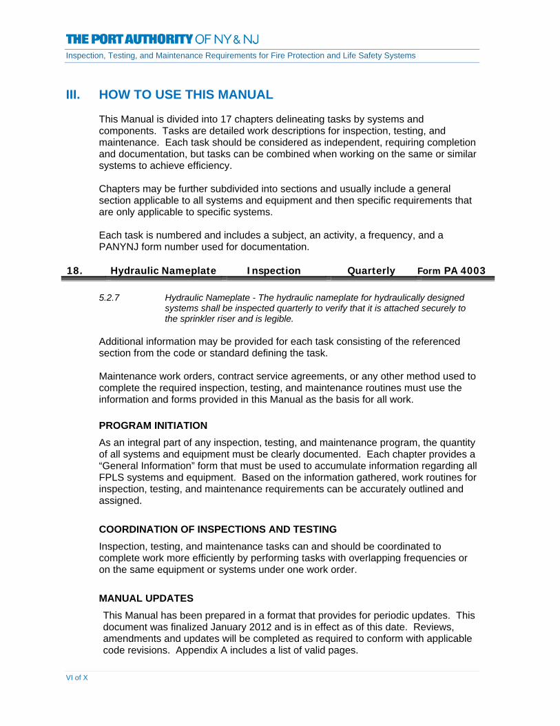
III. HOW TO USE THIS MANUAL
This Manual is divided into 17 chapters delineating tasks by systems and
components. Tasks are detailed work descriptions for inspection, testing, and maintenance. Each task should be considered as independent, requiring completion and documentation, but tasks can be combined when working on the same or similar systems to achieve efficiency.
Chapters may be further subdivided into sections and usually include a general section applicable to all systems and equipment and then specific requirements that are only applicable to specific systems.
Each task is numbered and includes a subject, an activity, a frequency, and a
PANYNJ form number used for documentation.
18. Hydraulic Nameplate Inspection Quarterly Form PA 4003
5.2.7 Hydraulic Nameplate - The hydraulic nameplate for hydraulically designed
systems shall be inspected quarterly to verify that it is attached securely to the sprinkler riser and is legible.
Additional information may be provided for each task consisting of the referenced section from the code or standard defining the task.
Maintenance work orders, contract service agreements, or any other method used to
complete the required inspection, testing, and maintenance routines must use the information and forms provided in this Manual as the basis for all work.
PROGRAM INITIATION As an integral part of any inspection, testing, and maintenance program, the quantity
of all systems and equipment must be clearly documented. Each chapter provides a “General Information” form that must be used to accumulate information regarding all FPLS systems and equipment. Based on the information gathered, work routines for inspection, testing, and maintenance requirements can be accurately outlined and assigned.
COORDINATION OF INSPECTIONS AND TESTING Inspection, testing, and maintenance tasks can and should be coordinated to
complete work more efficiently by performing tasks with overlapping frequencies or on the same equipment or systems under one work order.
MANUAL UPDATES This Manual has been prepared in a format that provides for periodic updates. This
document was finalized January 2012 and is in effect as of this date. Reviews, amendments and updates will be completed as required to conform with applicable code revisions. Appendix A includes a list of valid pages.
Inspection, Testing, and Maintenance Requirements for Fire Protection and Life Safety Systems
VII of X
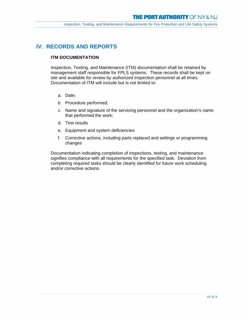
IV. RECORDS AND REPORTS ITM DOCUMENTATION
Inspection, Testing, and Maintenance (ITM) documentation shall be retained by management staff responsible for FPLS systems. These records shall be kept on site and available for review by authorized inspection personnel at all times. Documentation of ITM will include but is not limited to:
a. Date;
b. Procedure performed;
c. Name and signature of the servicing personnel and the organization’s name that performed the work;
d. Test results
e. Equipment and system deficiencies
f. Corrective actions, including parts replaced and settings or programming changes
Documentation indicating completion of inspections, testing, and maintenance signifies compliance with all requirements for the specified task. Deviation from completing required tasks should be clearly identified for future work scheduling and/or corrective actions.

Inspection, Testing, and Maintenance Requirements for Fire Protection and Life Safety Systems
VIII of X
V. DEFINITIONS
Fire Protection Systems: Approved devices, equipment and systems or combinations of systems used to
detect fire, activate an alarm, extinguish or control a fire, control or manage smoke and product of a fire or any combination thereof, including fire extinguishing systems, fire alarm systems, sprinkler systems and standpipe systems.
Inspection: A visual examination of a system or portion thereof to verify that it appears in an
operating condition and is free of physical damages.
Inspection, Testing, and Maintenance Service: A service program provided by a qualified contractor or qualified owner’s representative in which all components unique to the property’s systems are inspected and tested at the required times and necessary maintenance is provided. This program includes logging and retention of relevant records.
Life Safety Systems: Life Safety systems include fire protection devices, occupancy features, and building/floor designs that facilitate occupancy safety from fire emergencies including smoke and heat, and other non-fire related emergencies such as earthquakes and electric power failures. Life Safety systems include fire alarm notification devices, means of egress plans, areas of refuge, emergency lighting, exit signs, and smoke control systems.
Maintenance: Work performed to keep equipment operable or to make repairs.
Testing: A procedure used to determine the status of a system as intended by conducting periodic physical checks on water based fire systems such as water flow tests, fire pump tests, alarm tests, and trip tests of dry pipe, deluge or pre-action valves. These tests follow up on the original acceptance test at intervals specified in the appropriate chapter.

Inspection, Testing, and Maintenance Requirements for Fire Protection and Life Safety Systems
IX of X
VI. REFERENCES
New York City Building Code – 2008 Edition
New York City Fire Code – 2008 Edition
International Building Code – 2006 New Jersey Edition
New Jersey Fire Code – 2006 Edition
NATIONAL FIRE PROTECTION ASSOCIATION
NFPA 10 (2007): Standard for Portable Fire Extinguishers
NFPA 11 (2002): Low, Medium and High Expansion Foam
NFPA 12 (2002): Carbon Dioxide Extinguishing Systems
NFPA 12A (1997): Standard on Halon 1301 Fire Extinguishing Systems
NFPA 13 (2002): Standard for the Installation of Sprinkler Systems
NFPA 14 (2003): Standard for the Installation of Standpipe and Hose Systems
NFPA 16 (2003): Standard for the Installation of Foam-Water and Foam-Water Spray systems
NFPA 17 (2002): Dry Chemical Extinguishing Systems
NFPA 17A (2002): Wet Chemical Extinguishing Systems
NFPA 20 (1999): Standard for the Installation of Centrifugal Fire Pumps
NFPA 22 (1998): Water Tanks for Private Fire Protection
NFPA 24 (2007): Installation of Private Fire Service Mains and Their Appurtenances
NFPA 25 (2002): Standard for the Inspection, Testing and Maintenance of Water Based Fire Protection Systems
NFPA 33 (2000): Standard for Spray Application Using Flammable or Combustible Materials
NFPA 70 (2002): National Electrical Code
NFPA 72 (2002): National Fire Alarm Code
NFPA 80 (1999): Standard for Fire Doors and Other Opening Protectives

Inspection, Testing, and Maintenance Requirements for Fire Protection and Life Safety Systems
X of X
NFPA 90A (2002): Standard for the Installation of Air-Conditioning and Ventilating Systems
NFPA 92A (2006): Standard for Smoke-Control Systems Utilizing Barriers and Pressure Differences
NFPA 96 (2004): Standard for Ventilation Control and Fire Protection of Commercial Cooking Operations
NFPA 101 (2003): Life Safety Code
NFPA 110 (2002): Standard for Emergency and Standby Power Systems
NFPA 111 (2001) Standard on Stored Electrical Energy Emergency and Standby Power Systems
NFPA 409 (2001): Standard for Aircraft Hangars
NFPA 1962 (2003): Standard for the Inspection, Care, and Use of Fire Hose, Couplings, and Nozzles and the Service Testing of Fire Hose
NFPA 2001 (2004): Standard on Clean Agent Fire Extinguishing System
Inspection, Testing, and Maintenance Requirements for Fire Protection and Life Safety Systems
CHAPTER 1 – SPRINKLER SYSTEMS 9/30/2011 | Page 1-1
CHAPTER 1 – SPRINKLER SYSTEMS
DEFINITIONS Antifreeze Sprinkler System A wet pipe sprinkler system employing automatic sprinklers
that are attached to a piping system that contains an antifreeze solution and that are connected to a water supply. The antifreeze solution is discharged, followed by water, immediately upon operation of sprinklers opened by heat from a fire.
Branch Lines The pipes in which the sprinklers are placed, either directly
or through risers. Circulating Closed-Loop A wet pipe sprinkler system having non–fire protection
connections to automatic sprinkler systems in a closed-loop piping arrangement for the purpose of utilizing sprinkler piping to conduct water for heating or cooling, where water is not removed or used from the system but only circulated through the piping system.
Combined Dry Pipe-Preaction A sprinkler system employing automatic sprinklers attached Sprinkler System to a piping system containing air under pressure with a
supplemental detection system installed in the same areas as the sprinklers. Operation of the detection system actuates tripping devices that open dry pipe valves simultaneously and without loss of air pressure in the system. Operation of the detection system also opens listed air exhaust valves at the end of the feed main, which usually precedes the opening of sprinklers. The detection system also serves as an automatic fire alarm system.
Combined Standpipe and Sprinkler A system where the water piping services both 65-mm (21 2- System. in.) outlets for fire department use and outlets for automatic
sprinklers. Concealed Sprinkler A recessed sprinkler with cover plates. Control Valve A valve controlling flow to water-based fire protection
systems. Control valves do not include hose valves, inspector’s test valves, drain valves, trim valves for dry pipe, preaction and deluge valves, check valves, or relief valves.
Corrosion-Resistant Sprinkler A sprinkler fabricated with corrosion-resistant material, or
with special coatings or platings, to be used in an atmosphere that would normally corrode sprinklers.
Cross Mains The pipes supplying the branch lines, either directly or
through risers.

Inspection, Testing, and Maintenance Requirements for Fire Protection and Life Safety Systems
CHAPTER 1 – SPRINKLER SYSTEMS 9/30/2011 | Page 1-2
Deluge Sprinkler System. A sprinkler system employing open sprinklers that are
attached to a piping system that is connected to a water supply through a valve that is opened by the operation of a detection system installed in the same areas as the sprinklers. When this valve opens, water flows into the piping system and discharges from all sprinklers attached thereto.
Dry Pipe Sprinkler System. A sprinkler system employing automatic sprinklers that are
attached to a piping system containing air or nitrogen under pressure, the release of which (as from the opening of a sprinkler) permits the water pressure to open a valve known as a dry pipe valve, and the water then flows into the piping system and out the opened sprinklers.
Dry Sprinkler. A sprinkler secured in an extension nipple that has a seal at
the inlet end to prevent water from entering the nipple until the sprinkler operates.
Early Suppression Fast-Response A type of fast-response sprinkler that meets the criteria of (ESFR) Sprinkler 1.4.5.1(a)(1) of NFPA 13-1999 and is listed for its capability
to provide fire suppression of specific high-challenge fire hazards.
Extended Coverage Sprinkler. A type of spray sprinkler with maximum coverage areas as
specified in Sections 5.8 and 5.9 of NFPA 13-1999. Feed Mains The pipes supplying cross mains, either directly or through
risers. Flush Sprinkler A sprinkler in which all or part of the body, including the
shank thread, is mounted above the lower plane of the ceiling.
Gridded Sprinkler System. A sprinkler system in which parallel cross mains are
connected by multiple branch lines. An operating sprinkler will receive water from both ends of its branch line while other branch lines help transfer water between cross mains.
Hydraulically Designed System A calculated sprinkler system in which pipe sizes are
selected on a pressure loss basis to provide a prescribed water density, in gallons per minute per square foot (mm/min), or a prescribed minimum discharge pressure or flow per sprinkler, distributed with a reasonable degree of uniformity over a specified area.
Intermediate Level Sprinkler/Rack A sprinkler equipped with integral shields to protect its Storage Sprinkler operating elements from the discharge of sprinklers installed
at higher elevations. Large Drop Sprinkler A type of sprinkler that is capable of producing characteristic
large water droplets and that is listed for its capability to provide fire control of specific high-challenge fire hazards.
Inspection, Testing, and Maintenance Requirements for Fire Protection and Life Safety Systems
CHAPTER 1 – SPRINKLER SYSTEMS 9/30/2011 | Page 1-3
Looped Sprinkler System A sprinkler system in which multiple cross mains are tied
together so as to provide more than one path for water to flow to an operating sprinkler and branch lines are not tied together.
Main Drain. The primary drain connection located on the system riser
and also utilized as a flow test connection. Nozzles. A device for use in applications requiring special water
discharge patterns, directional spray, or other unusual discharge characteristics.
Old-Style/Conventional Sprinkler. A sprinkler that directs from 40 percent to 60 percent of the
total water initially in a downward direction and that is designed to be installed with the deflector either upright or pendent.
Open Sprinkler. A sprinkler that does not have actuators or heat-responsive elements.
Ornamental/Decorative Sprinkler. A sprinkler that has been painted or plated by the
manufacturer. Pendent Sprinkler A sprinkler designed to be installed in such a way that the
water stream is directed downward against the deflector. Pipe Schedule System A sprinkler system in which the pipe sizing is selected from a
schedule that is determined by the occupancy classification and in which a given number of sprinklers are allowed to be supplied from specific sizes of pipe.
Preaction Sprinkler System A sprinkler system employing automatic sprinklers that are
attached to a piping system that contains air that might or might not be under pressure, with a supplemental detection system installed in the same areas as the sprinklers.
Pressure Relief Valve A type of pressure relief device designed to both open and
close to maintain internal fluid pressure. Pressure-Reducing Valve A valve designed for the purpose of reducing the
downstream water pressure under both flowing (residual) and nonflowing (static) conditions.
Quick-Response Early Suppression A type of quick-response sprinkler that meets the criteria of (QRES) Sprinkler 1.4.5.1(a)(1) of NFPA 13-1999 and is listed for its capability
to provide fire suppression of specific fire hazards. Quick-Response Extended Coverage A type of quick-response sprinkler that meets the criteria of Sprinkler. 1.4.5.1(a)(1) of NFPA 13-1999 and complies with the
extended protection areas defined in Chapter 5 of NFPA 13- 1999.

Inspection, Testing, and Maintenance Requirements for Fire Protection and Life Safety Systems
CHAPTER 1 – SPRINKLER SYSTEMS 9/30/2011 | Page 1-4
Quick-Response (QR) Sprinkler. A type of spray sprinkler that meets the criteria of 1.4.5.1(a)(1) of NFPA 13- 1999 and is listed as a quick-response sprinkler for its intended use.
Recessed Sprinkler A sprinkler in which all or part of the body, other than the
shank thread, is mounted within a recessed housing. Risers The vertical supply pipes in a sprinkler system. Sectional Drain. A drain located beyond a sectional control valve that drains
only a portion of the system (e.g., a drain located beyond a floor control valve on a multi-story building).
Sidewall Sprinkler A sprinkler having special deflectors that are designed to
discharge most of the water away from the nearby wall in a pattern resembling one-quarter of a sphere, with a small portion of the discharge directed at the wall behind the sprinkler.
Special Sprinkler. A sprinkler that has been tested and listed as prescribed in
5.4.9 of NFPA 13-1999. Spray Sprinkler. A type of sprinkler listed for its capability to provide fire
control for a wide range of fire hazards. Sprinkler System For fire protection purposes, an integrated system of
underground and overhead piping designed in accordance with fire protection engineering standards. The installation includes one or more automatic water supplies. The portion of the sprinkler system aboveground is a network of specially sized or hydraulically designed piping installed in a building, structure, or area, generally overhead, and to which sprinklers are attached in a systematic pattern. The valve controlling each system riser is located in the system riser or its supply piping. Each sprinkler system riser includes a device for actuating an alarm when the system is in operation. The system is usually activated by heat from a fire and discharges water over the fire area.
Standard Spray Sprinkler. A spray sprinkler with maximum coverage areas as specified
in Sections 5.6 and 5.7 of NFPA 13-1999. Supervisory Device A device arranged to supervise the operative condition of
automatic sprinkler systems. System Riser The aboveground horizontal or vertical pipe between the
water supply and the mains (cross or feed) that contains a control valve (either directly or within its supply pipe) and a waterflow alarm device.
System Working Pressure The maximum anticipated static (nonflowing) or flowing
pressure applied to sprinkler system components exclusive of surge pressures.

Inspection, Testing, and Maintenance Requirements for Fire Protection and Life Safety Systems
CHAPTER 1 – SPRINKLER SYSTEMS 9/30/2011 | Page 1-5
Upright Sprinkler A sprinkler designed to be installed in such a way that the
water spray is directed upwards against the deflector. Water Spray. The use of water in a form having a predetermined pattern,
particle size, velocity, and density discharged from specially designed nozzles or devices. Water spray fixed systems are usually applied to special fire protection problems, since the protection can be specifically designed to provide for fire control, extinguishment, or exposure protection. Water spray fixed systems shall be permitted to be independent of, or supplementary to, other forms of protection.
Water Spray Fixed System. A special fixed pipe system connected to a reliable fire
protection water supply and equipped with water spray nozzles for specific water discharge and distribution over the surface or area to be protected. The piping system is connected to the water supply through an automatically or manually actuated valve that initiates the flow of water. An automatic valve is actuated by operation of automatic detection equipment installed in the same areas as the water spray nozzles. (In special cases, the automatic detection system also is located in another area.)
Wet Pipe Sprinkler System A sprinkler system employing automatic sprinklers attached
to a piping system containing water and connected to a water supply so that water discharges immediately from sprinklers opened by heat from a fire.
Inspection, Testing, and Maintenance Requirements for Fire Protection and Life Safety Systems
CHAPTER 1 – SPRINKLER SYSTEMS 9/30/2011 | Page 1-6
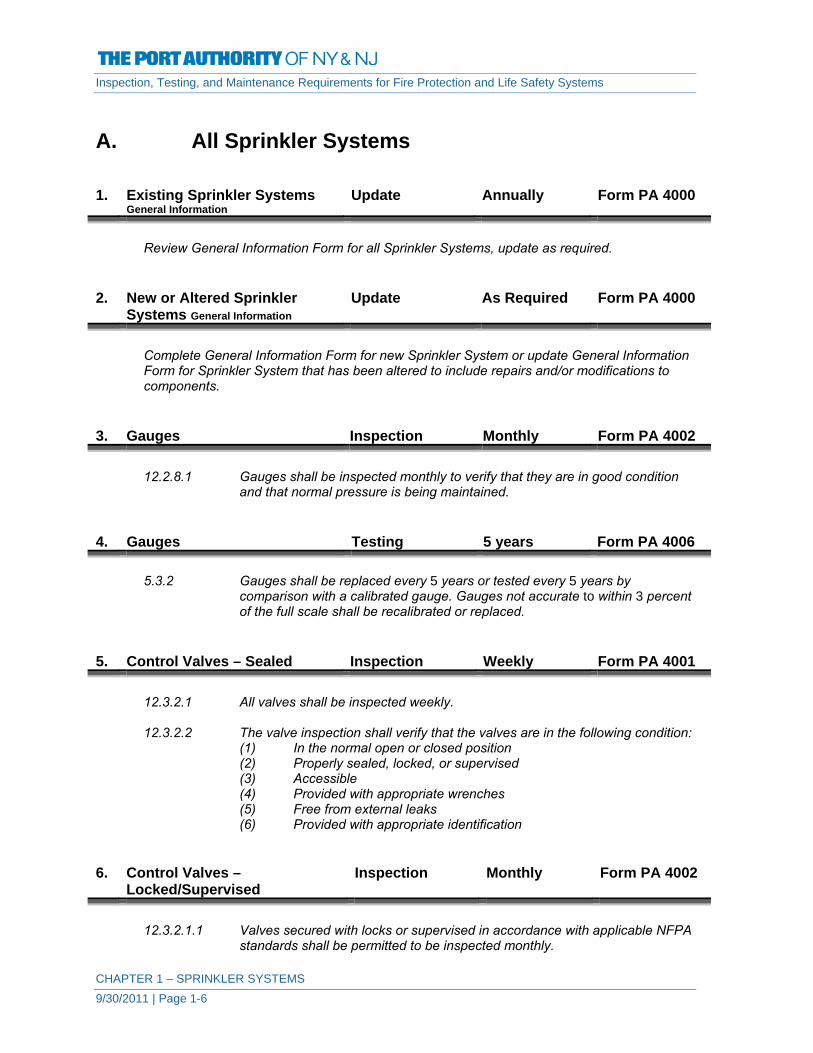
A. All Sprinkler Systems 1. Existing Sprinkler Systems
General Information Update Annually Form PA 4000
Review General Information Form for all Sprinkler Systems, update as required.
2. New or Altered Sprinkler
Systems General Information Update As Required Form PA 4000
Complete General Information Form for new Sprinkler System or update General Information Form for Sprinkler System that has been altered to include repairs and/or modifications to components.
3. Gauges Inspection Monthly Form PA 4002
12.2.8.1 Gauges shall be inspected monthly to verify that they are in good condition and that normal pressure is being maintained.
4. Gauges Testing 5 years Form PA 4006
5.3.2 Gauges shall be replaced every 5 years or tested every 5 years by comparison with a calibrated gauge. Gauges not accurate to within 3 percent of the full scale shall be recalibrated or replaced.
5. Control Valves – Sealed Inspection Weekly Form PA 4001
12.3.2.1 All valves shall be inspected weekly. 12.3.2.2 The valve inspection shall verify that the valves are in the following condition:
(1) In the normal open or closed position (2) Properly sealed, locked, or supervised (3) Accessible (4) Provided with appropriate wrenches (5) Free from external leaks (6) Provided with appropriate identification
6. Control Valves –
Locked/Supervised Inspection Monthly Form PA 4002
12.3.2.1.1 Valves secured with locks or supervised in accordance with applicable NFPA
standards shall be permitted to be inspected monthly.

Inspection, Testing, and Maintenance Requirements for Fire Protection and Life Safety Systems
CHAPTER 1 – SPRINKLER SYSTEMS 9/30/2011 | Page 1-7
12.3.2.2 The valve inspection shall verify that the valves are in the following condition:
(1) In the normal open or closed position (2) Properly sealed, locked, or supervised (3) Accessible (4) Provided with appropriate wrenches (5) Free from external leaks (6) Provided with appropriate identification
7. Control Valves Testing Annually Form PA 4005
12.3.3.1 Each control valve shall be operated annually through its full range and returned to its normal position. The testing required by 12.3.3.1 should include counting the number of turns needed to fully close and open the valve. Also, the valve stem should be lubricated before opening and closing.
12.3.3.2 Post indicator valves shall be opened until spring or torsion is felt in the rod,
indicating that the rod has not become detached from the valve. 8. Control Valves Testing Semi-Annually Form PA 4004
12.3.3.5.1 Valve supervisory switches shall be tested semiannually.
12.3.3.5.2 A distinctive signal shall indicate movement from the valve’s normal position during either the first two revolutions of a hand wheel or when the stem of the valve has moved one-fifth of the distance from its normal position.
12.3.3.5.3 The signal shall not be restored at any valve position except the normal
position.
9. Control Valves Maintenance Annually Form PA 4011
12.3.4.1 The operating stems of outside screw and yoke valves shall be lubricated annually.
12.3.4.2 The valve then shall be completely closed and reopened to test its operation
and distribute the lubricant. 10. Alarm Valves – Exterior Inspection Monthly Form PA 4002
12.4.1.1 Alarm valves shall be externally inspected monthly and shall verify the
following: (1) The gauges indicate normal supply water pressure is being
maintained. (2) The valve is free of physical damage. (3) All valves are in the appropriate open or closed position. (4) The retarding chamber or alarm drains are not leaking.

Inspection, Testing, and Maintenance Requirements for Fire Protection and Life Safety Systems
CHAPTER 1 – SPRINKLER SYSTEMS 9/30/2011 | Page 1-8
11. Alarm Valves – Interior
Strainers/Filters/Orifices Inspection 5 Years Form PA 4006
12.4.1.2 Alarm valves and their associated strainers, filters, and restriction orifices
shall be inspected internally every 5 years unless tests indicate a greater frequency is necessary.
12. Alarm Valves Maintenance As Necessary Form PA 4006
12.4.1.3.1 Internal components shall be cleaned/repaired as necessary in accordance
with the manufacturer’s instructions.
Document maintenance completed in Notes on Form 4006. 13. Pressure Reducing & Relief
Valves – Sprinkler System Inspection Quarterly Form PA 4150
12.5.1.1 All valves shall be inspected quarterly to verify that the valves are in the
following condition: (1) In the open position (2) Not leaking (3) Maintaining downstream pressures in accordance with the design
criteria (4) In good condition, with handwheels installed and unbroken
14. Pressure Reducing & Relief
Valves – Sprinkler Systems Testing Annually Form PA 4150
12.5.1.3 A partial flow test adequate to move the valve from its seat shall be
conducted annually. 15. Pressure Reducing & Relief
Valves – Sprinkler System Testing 5 Years Form PA 4150
12.5.1.2 A full flow test shall be conducted on each valve at 5-year intervals and shall
be compared to previous test results.
Document results of test in Notes on Form 4150.

Inspection, Testing, and Maintenance Requirements for Fire Protection and Life Safety Systems
CHAPTER 1 – SPRINKLER SYSTEMS 9/30/2011 | Page 1-9
16. Alarm Devices Inspection Quarterly Form PA 4003
5.2.6 Alarm devices shall be inspected quarterly to verify that they are free of
physical damage. 17. Alarm Devices Testing Quarterly Form PA 4003
5.3.3.1 Water-flow devices including, but not limited to, mechanical water motor
gongs and pressure switch type shall be tested quarterly.
5.3.3.3 Testing the water-flow alarms on wet pipe systems shall be accomplished by opening the inspector’s test connection.
5.3.3.3.1 Where freezing weather conditions or other circumstances prohibit use of the
inspector’s test connection, the bypass connection shall be permitted to be used.
18. Hydraulic Nameplate Inspection Quarterly Form PA 4003
5.2.7 Hydraulic Nameplate - The hydraulic nameplate for hydraulically designed
systems shall be inspected quarterly to verify that it is attached securely to the sprinkler riser and is legible.
19. Hanger/Seismic Bracing Inspection Annually Form PA 4005
5.2.3 Hangers and Seismic Braces. Sprinkler pipe hangers and seismic braces shall be inspected annually from the floor level.
5.2.3.1 Hangers and seismic braces shall not be damaged or loose.
5.2.3.2 Hangers and seismic braces that are damaged or loose shall be replaced or
refastened.
5.2.3.3 Hangers and seismic braces installed in concealed spaces such as above suspended ceilings shall not require inspection.
5.2.3.4 Hangers installed in areas that are inaccessible for safety considerations due
to process operations shall be inspected during each scheduled shutdown. 20. Sprinklers Inspection Annually Form PA 4005
5.2.1.1 Sprinklers shall be inspected from the floor level annually.
5.2.1.1.1 Sprinklers shall not show signs of leakage; shall be free of corrosion, foreign
materials, paint, and physical damage; and shall be installed in the proper orientation (e.g., upright, pendent, or sidewall).

Inspection, Testing, and Maintenance Requirements for Fire Protection and Life Safety Systems
CHAPTER 1 – SPRINKLER SYSTEMS 9/30/2011 | Page 1-10
5.2.1.1.2 Any sprinkler shall be replaced that has signs of leakage; is painted,
corroded, damaged, or loaded; or in the improper orientation.
5.2.1.1.3 Glass bulb sprinklers shall be replaced if the bulbs have emptied.
5.2.1.1.4 Sprinklers installed in concealed spaces such as above suspended ceilings shall not require inspection.
5.2.1.1.5 Sprinklers installed in areas that are inaccessible for safety considerations
due to process operations shall be inspected during each scheduled shutdown.
5.2.1.2 Unacceptable obstructions to spray patterns shall be corrected.
5.2.1.3 The supply of spare sprinklers shall be inspected annually for the following:
(1) The proper number and type of sprinklers (2) A sprinkler wrench for each type of sprinkler
21. Sprinklers Testing As Identified Form PA 4008
5.3.1.1.1 Where sprinklers have been in service for 50 years, they shall be replaced or
representative samples from one or more sample areas shall be tested. Test procedures shall be repeated at 10-year intervals.
5.3.1.1.1.1 Sprinklers manufactured prior to 1920 shall be replaced.
5.3.1.1.1.2 Sprinklers manufactured using fast-response elements that have been in
service for 20 years shall be tested. They shall be retested at 10-year intervals.
5.3.1.1.1.3 Representative samples of solder-type sprinklers with a temperature
classification of extra high 163°C (325°F) or greater that is exposed to semi-continuous to continuous maximum allowable ambient temperature conditions shall be tested at 5-year intervals.
5.3.1.1.1.4 Where sprinklers have been in service for 75 years, they shall be replaced or
representative samples from one or more sample areas shall be submitted to a recognized testing laboratory acceptable to the authority having jurisdiction for field service testing. Test procedures shall be repeated at 5-year intervals.
5.3.1.1.1.5 Dry sprinklers that have been in service for 10 years shall be tested or
replaced. If maintained and serviced, they shall be retested at 10-year intervals.
5.3.1.1.2 Where sprinklers are subjected to harsh environments, including corrosive
atmospheres and corrosive water supplies, on a 5-year basis, sprinklers shall either be replaced or representative sprinkler samples shall be tested.
5.3.1.1.3 Where historical data indicates, longer intervals between testing shall be
permitted.

Inspection, Testing, and Maintenance Requirements for Fire Protection and Life Safety Systems
CHAPTER 1 – SPRINKLER SYSTEMS 9/30/2011 | Page 1-11
5.3.1.2 A representative sample of sprinklers for testing per 5.3.1.1.1 shall consist of
a minimum of not less than 4 sprinklers or 1 percent of the number of sprinklers per individual sprinkler sample, whichever is greater.
5.3.1.3 Where one sprinkler within a representative sample fails to meet the test
requirement, all sprinklers represented by that sample shall be replaced.
5.3.1.3.1 Manufacturers shall be permitted to make modifications to their own sprinklers in the field with listed devices that restore the original performance as intended by the listing, where acceptable to the authority having jurisdiction.
22. Pipe and Fittings Inspection Annually Form PA 4005
5.2.2 Pipe and Fittings. Sprinkler pipe and fittings shall be inspected annually from the floor level.
5.2.2.1 Pipe and fittings shall be in good condition and free of mechanical damage,
leakage, corrosion, and misalignment.
5.2.2.2 Sprinkler piping shall not be subjected to external loads by materials either resting on the pipe or hung from the pipe.
5.2.2.3 Pipe and fittings installed in concealed spaces such as above suspended
ceilings shall not require inspection.
5.2.2.4 Pipe installed in areas that are inaccessible for safety considerations due to process operations shall be inspected during each scheduled shutdown.
23. Main Drain Testing Annually Form PA 4005
12.2.6 Main Drain Test. A main drain test shall be conducted annually at each water-based fire protection system riser to determine whether there has been a change in the condition of the water supply piping and control valves. (See also 12.3.4.2. under Item Number A– 9 above).
12.3.3.4 A main drain test shall be conducted annually at each system riser and any
time the valve is closed at each system riser or feed main after the control valve has been closed to determine whether there has been a change in the condition of the water supply piping and control valves.
24. Main Drain Testing Quarterly Form PA 4003
12.2.6.1 Systems where the sole water supply is through a backflow preventer and/or
pressure reducing valves, the main drain test of at least one system downstream of the device shall be conducted on a quarterly basis.
Inspection, Testing, and Maintenance Requirements for Fire Protection and Life Safety Systems
CHAPTER 1 – SPRINKLER SYSTEMS 9/30/2011 | Page 1-12
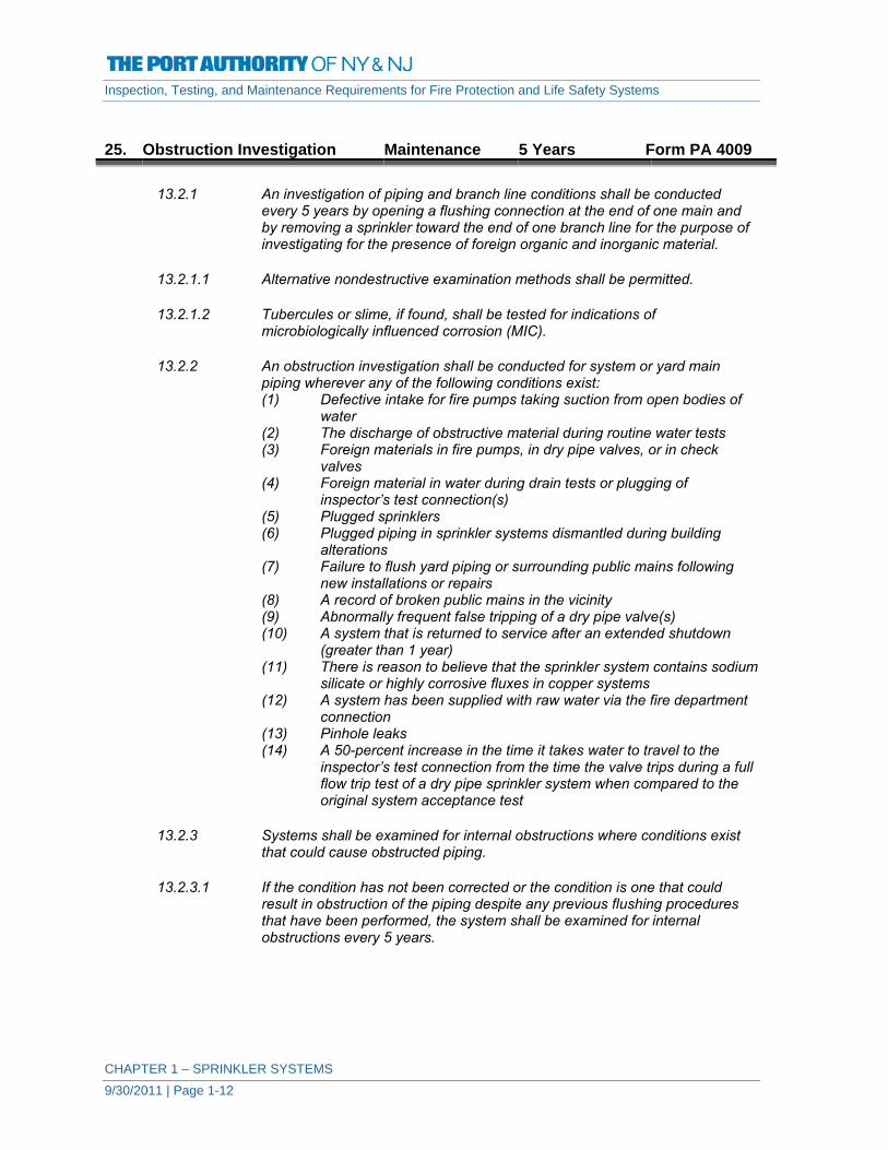
25. Obstruction Investigation Maintenance 5 Years Form PA 4009
13.2.1 An investigation of piping and branch line conditions shall be conducted
every 5 years by opening a flushing connection at the end of one main and by removing a sprinkler toward the end of one branch line for the purpose of investigating for the presence of foreign organic and inorganic material.
13.2.1.1 Alternative nondestructive examination methods shall be permitted.
13.2.1.2 Tubercules or slime, if found, shall be tested for indications of
microbiologically influenced corrosion (MIC).
13.2.2 An obstruction investigation shall be conducted for system or yard main piping wherever any of the following conditions exist: (1) Defective intake for fire pumps taking suction from open bodies of
water (2) The discharge of obstructive material during routine water tests (3) Foreign materials in fire pumps, in dry pipe valves, or in check
valves (4) Foreign material in water during drain tests or plugging of
inspector’s test connection(s) (5) Plugged sprinklers (6) Plugged piping in sprinkler systems dismantled during building
alterations (7) Failure to flush yard piping or surrounding public mains following
new installations or repairs (8) A record of broken public mains in the vicinity (9) Abnormally frequent false tripping of a dry pipe valve(s) (10) A system that is returned to service after an extended shutdown
(greater than 1 year) (11) There is reason to believe that the sprinkler system contains sodium
silicate or highly corrosive fluxes in copper systems (12) A system has been supplied with raw water via the fire department
connection (13) Pinhole leaks (14) A 50-percent increase in the time it takes water to travel to the
inspector’s test connection from the time the valve trips during a full flow trip test of a dry pipe sprinkler system when compared to the original system acceptance test
13.2.3 Systems shall be examined for internal obstructions where conditions exist
that could cause obstructed piping.
13.2.3.1 If the condition has not been corrected or the condition is one that could result in obstruction of the piping despite any previous flushing procedures that have been performed, the system shall be examined for internal obstructions every 5 years.

Inspection, Testing, and Maintenance Requirements for Fire Protection and Life Safety Systems
CHAPTER 1 – SPRINKLER SYSTEMS 9/30/2011 | Page 1-13
B. Automatic Wet Sprinkler Systems In addition to A above, the following is required for wet sprinkler systems. 1. Alarm Devices Testing Semi-Annually Form PA 4004
5.3.3.2 Vane-type water-flow devices shall be tested semiannually.
2. Building Heating System Inspection Annually Form PA 4005
5.2.5 Annually, prior to the onset of freezing weather, buildings with wet pipe
systems shall be inspected to verify that windows, skylights, doors, ventilators, other openings and closures, blind spaces, unused attics, stair towers, roof houses, and low spaces under buildings do not expose waterfilled sprinkler piping to freezing and to verify that adequate heat [minimum 4.4°C (40°F)] is available.
C. Automatic Dry Pipe Sprinkler Systems In addition to A above, the following is required for dry-pipe sprinkler systems. 1. Heating System Inspection Daily Form PA 4010
12.4.4.1.1 Valve enclosure heating equipment shall be inspected daily during cold
weather for its ability to maintain a minimum temperature of at least 4°C (40°F).
2. Heating System Inspection Weekly Form PA 4001
12.4.4.1.1.1 Valve enclosures equipped with low temperature alarms shall be inspected
weekly. 3. Alarm Devices Inspection Annually Form PA 4005
12.4.4.1.1.2 Low temperature alarms, if installed in valve enclosures, shall be inspected
annually at the beginning of the heating season.

Inspection, Testing, and Maintenance Requirements for Fire Protection and Life Safety Systems
CHAPTER 1 – SPRINKLER SYSTEMS 9/30/2011 | Page 1-14
4. Alarm Devices Testing Annually Form PA 4005
12.4.4.2.7 Low temperature alarms, if installed in valve enclosures, shall be tested
annually at the beginning of the heating season. 5. Alarm Devices Testing Quarterly Form PA 4003
5.3.3.5 Testing the water-flow alarm on dry pipe, pre-action, or deluge systems shall
be accomplished by using the bypass connection.
12.4.4.2.6 Low air pressure alarms, if provided, shall be tested quarterly in accordance with the manufacturer’s instructions.
NFPA 72 High-or low-air pressure switch – Switch shall be operated. Receipt of signal Table obtained where the required pressure is increased or decreased a maximum 10.4.2.2-13(h) 70 kPa (10 psi) from the required pressure level shall be verified.
6. Gauges Inspection Weekly Form PA 4001
12.4.4.1.2 Gauges shall be inspected weekly.
(A) The gauge on the supply side of the dry pipe valve shall indicate that the normal supply water pressure is being maintained.
(B) The gauge on the system side of the dry pipe valve shall indicate that the proper ratio of air or nitrogen pressure to water supply pressure is being maintained in accordance with the manufacturer’s instructions.
(C) The gauge on the quick-opening device, if provided, shall indicate the same pressure as the gauge on the system side of the dry pipe valve.
7. Gauges Inspection Monthly Form PA 4002
12.4.4.1.3 Systems equipped with low air or nitrogen pressure alarms shall be
inspected monthly. 8. Alarm Valves – Exterior Inspection Monthly Form PA 4002
12.4.4.1.4 The dry pipe valve shall be externally inspected monthly to verify the
following: (1) The valve is free of physical damage. (2) All trim valves are in the appropriate open or closed position. (3) The intermediate chamber is not leaking.

Inspection, Testing, and Maintenance Requirements for Fire Protection and Life Safety Systems
CHAPTER 1 – SPRINKLER SYSTEMS 9/30/2011 | Page 1-15
9. Alarm Valves – Interior Inspection Annually Form PA 4005
12.4.4.1.5 The interior of the dry pipe valve shall be inspected annually when the trip
test is conducted. 10. Alarm Valves Testing Quarterly Form PA 4003
12.4.4.2.1 The priming water level shall be tested quarterly.
11. Alarm Valves Testing Annually Form PA 4005
12.4.4.2.2 Each dry pipe valve shall be trip tested annually during warm weather.
12.4.4.2.2.1 Dry pipe valves protecting freezers shall be trip tested in a manner that does
not introduce moisture into the piping in the freezers.
12.4.4.2.2.3 During those years when full flow testing in accordance with 12.4.4.2.2.2 is not required, each dry pipe valve shall be trip tested with the control valve partially open.
12.4.4.2.5 A tag or card that shows the date on which the dry pipe valve was last
tripped and the name of the person and organization conducting the test shall be attached to the valve.
12.4.4.2.5.1 Separate records of initial air and water pressure, tripping air pressure, and
dry pipe valve operating conditions shall be maintained on the premises for comparison with previous test results.
12.4.4.2.8 Automatic air pressure maintenance devices, if provided, shall be tested
annually during the dry pipe valve trip test in accordance with the manufacturer’s instructions.
12. Alarm Valves Testing 3 Years Form PA 4007
12.4.4.2.2.2 Every 3 years and whenever the system is altered, the dry pipe valve shall
be trip tested with the control valve fully open and the quick-opening device, if provided, in service.
12.4.4.2.5.2 Records of tripping time shall be maintained for full flow trip tests.
13. Quick Opening Devices Testing Quarterly Form PA 4003
12.4.4.2.4 Quick-opening devices, if provided, shall be tested quarterly.

Inspection, Testing, and Maintenance Requirements for Fire Protection and Life Safety Systems
CHAPTER 1 – SPRINKLER SYSTEMS 9/30/2011 | Page 1-16
14. Dry-Pipe System Maintenance Annually or
As Needed Form PA 4011
12.4.4.3.1 Leaks resulting in air pressure losses greater than 0.7 bar (10 psi) per week
shall be located and repaired. 12.4.4.3.2 During the annual trip test, the interior of the dry pipe valve shall be cleaned
thoroughly and parts replaced or repaired as necessary.
5.4.2.2 Air driers shall be maintained in accordance with the manufacturer’s instructions.
5.4.2.3 Compressors used in conjunction with dry pipe sprinkler systems shall be
maintained in accordance with the manufacturer’s instructions. 15. Dry-Pipe System Maintenance Semi-Annually
or As Needed Form PA 4007
12.4.4.3.3 Low points in dry pipe sprinkler systems shall be drained after each operation
and before the onset of freezing weather conditions.
Note: Depending on the condition and history of the system, increased frequencies may be required. Document all dates in the Notes section.
D. Automatic Pre-Action Sprinkler Systems In addition to A above, the following is required for Pre-Action sprinkler systems. 1. Gauges Inspection Monthly Form PA 4002
12.4.3.1.4 The gauge monitoring the pre-action system supervisory air pressure, if
provided, shall be inspected monthly to verify that it indicates that normal pressure is being maintained.
2. Gauges Testing Monthly Form PA 4002
12.4.3.1.5 The gauge monitoring the detection system pressure, if provided, shall be
tested monthly to verify that it indicates that normal pressure is being maintained.
Document testing completed in Notes on Form 4002.

Inspection, Testing, and Maintenance Requirements for Fire Protection and Life Safety Systems
CHAPTER 1 – SPRINKLER SYSTEMS 9/30/2011 | Page 1-17
3. Heating System Inspection Daily Form PA 4010
12.4.3.1 Valve enclosure heating equipment for pre-action and deluge valves subject
to freezing shall be inspected daily during cold weather for its ability to maintain a minimum temperature of at least 4°C (40°F).
4. Heating System Inspection Weekly Form PA 4001
12.4.3.1.1 Valve enclosures (subject to freezing) equipped with low temperature alarms shall be inspected weekly.
5. Alarm Devices Testing Annually Form PA 4005
12.4.3.1.2 Low temperature alarms, if installed in valve enclosures, shall be inspected
annually at the beginning of the heating season. 6. Alarm Devices Testing Quarterly Form PA 4003
12.4.3.2.10 Low air pressure alarms, if provided, shall be tested quarterly in accordance
with the manufacturer’s instructions. 7. Alarm Valves – Exterior Inspection Monthly Form PA 4002
12.4.3.1.6 The pre-action or deluge valve shall be externally inspected monthly to verify
the following: (1) The valve is free from physical damage. (2) All trim valves are in the appropriate open or closed position. (3) The valve seat is not leaking. (4) Electrical components are in service.
8. Alarm Valves – Interior Inspection Annually Form PA 4005
12.4.3.1.7 The interior of the pre-action or deluge valve and the condition of detection
devices shall be inspected annually when the trip test is conducted. 9. Alarm Valves – Interior Inspection 5 Years Form PA 4006
12.4.3.1.7.1 Internal inspection of valves that can be reset without removal of a faceplate
shall be permitted to be conducted every 5 years.
Inspection, Testing, and Maintenance Requirements for Fire Protection and Life Safety Systems
CHAPTER 1 – SPRINKLER SYSTEMS 9/30/2011 | Page 1-18
10. Alarm Valves Testing Quarterly Form PA 4003
12.4.3.2.1 The priming water level in supervised pre-action systems shall be tested
quarterly for compliance with the manufacturer’s instructions. 11. Alarm Valves Testing Annually Form PA 4005
12.4.3.2.2 Each deluge or pre-action valve shall be trip tested annually at full flow in
warm weather and in accordance with the manufacturer’s instructions. Protection shall be provided for any devices or equipment subject to damage by system discharge during tests.
12.4.3.2.2.1 Where the nature of the protected property is such that water cannot be
discharged for test purposes, the trip test shall be conducted in a manner that does not necessitate discharge in the protected area.
12.4.3.2.2.2 Where the nature of the protected property is such that water cannot be
discharged unless protected equipment is shut down (e.g., energized electrical equipment), a full flow system test shall be conducted at the next scheduled shutdown. In all cases, the test frequency shall not exceed 3 years.
12.4.3.2.2.3 Pre-action or deluge valves protecting freezers shall be trip tested in a
manner that does not introduce moisture into the piping in the freezer.
12.4.3.2.3 The water discharge patterns from all open sprinklers or spray nozzles shall be observed to ensure that patterns are not impeded by plugging and to ensure that they are correctly positioned and that obstructions do not prevent discharge patterns from wetting surfaces to be protected.
12.4.3.2.3.1 Where obstructions occur, the piping and sprinklers or nozzles shall be
cleaned and the system retested.
12.4.3.2.5 Multiple Systems. The maximum number of systems expected to operate in case of fire shall be tested simultaneously to check the adequacy of the water supply.
12.4.3.2.6 Manual Operation. Manual actuation devices shall be operated annually.
12.4.3.2.12 Automatic air pressure maintenance devices, if provided, shall be tested
yearly at the time of the annual pre-action or deluge valve trip test, in accordance with the manufacturer’s instructions.

Inspection, Testing, and Maintenance Requirements for Fire Protection and Life Safety Systems
CHAPTER 1 – SPRINKLER SYSTEMS 9/30/2011 | Page 1-19
12. Pre-action System Maintenance Annually or
As Needed Form PA 4011
12.4.3.3.1 Leaks causing drops in supervisory pressure sufficient to sound warning
alarms and electrical malfunctions causing alarms to sound shall be located and repaired.
12.4.3.3.2 During the annual trip test, the interior of the pre-action or deluge valve shall
be cleaned thoroughly and the parts replaced or repaired as necessary.
12.4.3.3.2.1 Interior cleaning and parts replacement or repair shall be permitted every 5 years for valves that can be reset without removal of a faceplate.
12.4.3.3.3 Low points in pre-action or deluge systems shall be drained after each
operation and before the onset of freezing weather conditions.
12.4.3.3.4 Additional maintenance as required by the manufacturer’s instructions shall be provided.
E. Automatic Deluge Sprinkler Systems In addition to A above, the following is required for deluge sprinkler systems. 1. Gauges Testing Monthly Form PA 4002
12.4.3.1.5 The gauge monitoring the detection system pressure, if provided, shall be
tested monthly to verify that it indicates that normal pressure is being maintained.
Document testing completed in Notes on Form 4002.
2. Heating System Inspection Daily Form PA 4010
12.4.3.1 Valve enclosure heating equipment for pre-action and deluge valves subject
to freezing shall be inspected daily during cold weather for its ability to maintain a minimum temperature of at least 4°C (40°F).
3. Heating System Inspection Weekly Form PA 4001
12.4.3.1.1 Valve enclosures (subject to freezing) equipped with low temperature alarms shall be inspected weekly.
Inspection, Testing, and Maintenance Requirements for Fire Protection and Life Safety Systems
CHAPTER 1 – SPRINKLER SYSTEMS 9/30/2011 | Page 1-20
4. Alarm Devices Testing Annually Form PA 4005
12.4.3.1.2 Low temperature alarms, if installed in valve enclosures, shall be inspected
annually at the beginning of the heating season. 5. Alarm Valves – Exterior Inspection Monthly Form PA 4002
12.4.3.1.6 The pre-action or deluge valve shall be externally inspected monthly to verify
the following: (1) The valve is free from physical damage. (2) All trim valves are in the appropriate open or closed position. (3) The valve seat is not leaking. (4) Electrical components are in service.
6. Alarm Valves – Interior Inspection Annually Form PA 4005
12.4.3.1.7 The interior of the pre-action or deluge valve and the condition of detection
devices shall be inspected annually when the trip test is conducted. 7. Alarm Valves – Interior Inspection 5 Years Form PA 4006
12.4.3.1.7.1 Internal inspection of valves that can be reset without removal of a faceplate
shall be permitted to be conducted every 5 years. 8. Alarm Valves Testing Annually Form PA 4005
12.4.3.2.2 Each deluge or pre-action valve shall be trip tested annually at full flow in
warm weather and in accordance with the manufacturer’s instructions. Protection shall be provided for any devices or equipment subject to damage by system discharge during tests.
12.4.3.2.2.1 Where the nature of the protected property is such that water cannot be
discharged for test purposes, the trip test shall be conducted in a manner that does not necessitate discharge in the protected area.
12.4.3.2.2.2 Where the nature of the protected property is such that water cannot be
discharged unless protected equipment is shut down (e.g., energized electrical equipment), a full flow system test shall be conducted at the next scheduled shutdown. In all cases, the test frequency shall not exceed 3 years.
12.4.3.2.2.3 Pre-action or deluge valves protecting freezers shall be trip tested in a
manner that does not introduce moisture into the piping in the freezer.
Inspection, Testing, and Maintenance Requirements for Fire Protection and Life Safety Systems
CHAPTER 1 – SPRINKLER SYSTEMS 9/30/2011 | Page 1-21
12.4.3.2.3 The water discharge patterns from all open sprinklers or spray nozzles shall be observed to ensure that patterns are not impeded by plugging and to ensure that they are correctly positioned and that obstructions do not prevent discharge patterns from wetting surfaces to be protected.
12.4.3.2.3.1 Where obstructions occur, the piping and sprinklers or nozzles shall be
cleaned and the system retested.
12.4.3.2.5 Multiple Systems. The maximum number of systems expected to operate in case of fire shall be tested simultaneously to check the adequacy of the water supply.
12.4.3.2.6 Manual Operation. Manual actuation devices shall be operated annually.
9. Deluge System Maintenance Annually or
As Needed Form PA 4011
12.4.3.3.2 During the annual trip test, the interior of the pre-action or deluge valve shall
be cleaned thoroughly and the parts replaced or repaired as necessary.
12.4.3.3.2.1 Interior cleaning and parts replacement or repair shall be permitted every 5 years for valves that can be reset without removal of a faceplate.
12.4.3.3.3 Low points in pre-action or deluge systems shall be drained after each
operation and before the onset of freezing weather conditions.
12.4.3.3.4 Additional maintenance as required by the manufacturer’s instructions shall be provided.

.
SPRINKLER SYSTEMS - GENERAL INFORMATION PA 4000 / 03-12
Original Installation Date: U.E.I. (Unique Element Identification):
Building ID: System ID: Date: Description of Protected Area:
General
Type of sprinkler system Wet Dry Deluge Preaction Make and model of sprinkler valve
Location of sprinkler valve
Is the valve room in heated? Yes No
Does heated room have low-temperature alarm? Yes No
Is system hydraulically calculated? Yes No
If yes, is hydraulic information sign provided at valve? Yes No
Control Valves Number of Control Valves in Alarm Valve Enclosure
How are valves supervised? Seated Locked Tamper Switch
Are valves indentified with signs? Yes No
Fire Department Connections Number and location of connections
Are identification signs provided? Yes No Water Supply Water supplied from Municipal System Fire Pump Supply Pressure If provided by Fire Pump Fire Pump ID Location Fire Pump maintained by
Wet Systems
Is building adequately heated? Yes No
Location of Inspector's Test Point
Dry Systems
Air Pressure on System
Manufacturer and Model of Quick Opening Device (if provided)
Location of Inspector's Test Point
PreAction/Deluge System Number and Type of Initiating Devices Location of Manual Release
Notes:

SPRINKLER SYSTEMS - WEEKLY INSPECTION PA 4001 / 03-12
Building ID: System ID / U.E.I.:
1. If valves are sealed, note “yes” in this block. If any are not sealed, reseal and note “resealed” in this block.
2.
If all sprinklers are in good condition and storage is maintained at least 18 in. (46 cm) below the sprinklers, note “yes” in block. If not, see that corrections are made and briefly describe under “notes.”
3. - 6. Record pressure readings in psi (bar). A loss of more than 10% should be investigated. 7. Gauges shall be inspected weekly.
8. Valve enclosure (subject to freezing) shall be inspected weekly.
9.
Record any notes about the system that the inspector believes to be significant. Place a number in this box and number the corresponding note on reverse.
Date Inspector Valves Sealed
(1)
Sprinklers OK (2)
Sprinkler Alarm Valve
(3)
Dry Pipe Valve
(4)
Preaction Valve
(5)
Deluge Valve Water
Pressure (6)
Notes (9) Gauges
(7)
HeatingSystem
(8) Air
Press. Water Press
Air Press.
Water Press

SPRINKLER SYSTEMS - MONTHLY INSPECTION PA 4002 / 03-12
Building ID: System ID / U.E.I.:
Y = Satisfactory N = Unsatisfactory (explain below) N/A = Not applicable
Date
Inspector
Valves Open, Locked or Tamper Confirm valves are open. If valves are locked, note "yes" in this block. If any are not locked, relock and note "relocked" in this block.
Alarm Valves - Exterior Inspect alarm valves to assure that the valve in not leaking, free of physical damage, trim valves are in appropriate open or closed positions, and electrical components are in service.
Spare Sprinklers Assure there is proper number and type of sprinklers and a sprinkler wrench.
Alarm Devices Check for physical damage and that electrical connections are secure.
Water Pressure Record pressure readings in psi (bar). A loss of more than 10% should be investigated.
Gauges Gauges shall be inspected monthly to verify that they are in good condition.
Supervisory Air Gauges Verify that the pre-action supervisory air indicated that normal pressure is maintained.
Notes:

SPRINKLER SYSTEMS - QUARTERLY INSPECTION AND TESTS PA 4003 / 03-12
Building ID: System ID / U.E.I.:
Y = Satisfactory N = Unsatisfactory (explain below) N/A = Not Applicable
Date
Inspector
Main Drain Test Record the static water supply pressure in psi (bar) as indicated on the lower pressure gauge. Open the main drain and allow water flow to stabilize.
Record the residual water supply pressure while water is flowing from the 2-in. (51-mm) main drain as indicated on the lower pressure gauge in psi (bar). Close the main drain (slowly).
Fire Department Connections Verify connection is visible and accessible, not damaged, caps or plugs are in place, identification sign is in place, and automatic drain is working properly.
Wet Pipe System Flow Alarm Test water-flow alarms by opening the inspector’s test valve. (Notify alarm company to avoid false alarms.)
Dry Pipe/Pre-Action Priming Level Check priming water level by opening the test valve and checking for a small amount of water to discharge. If no water flows out of the test line, add priming water to bottom of handhole.
Dry Pipe System High and Low-Air-Pressure Alarm Confirm operation of high and low pressure alarms, record air pressure at which high and low pressure alarms activate.
System Air Pressure: High Set Point
Low Set Point
Dry Pipe System Flow Alarm Open the alarm bypass valve. (Notify alarm company to avoid false alarms.)
Quick-Opening Device Test in accordance with manufacturer’s instructions.
Preaction System Flow Alarm Open the alarm bypass valve. Prime system to bottom of hand hole. (Notify alarm company to avoid false alarms.)
Deluge System Flow Alarm Open the alarm bypass valve. (Notify alarm company to avoid false alarms.)
Control Valves Close valves and reopen until spring or tension is felt—back valve 1/4 turn.
Hydraulic Nameplate If system was hydraulically calculated, assure nameplate is legible and securely attached to riser.
Alarm Devices: Verify that devices are free of physical damages
Notes: Record any notes about the system that the inspector believes to be significant. Place a number in this block and number the corresponding note on the reverse of this form.

AUTOMATIC SPRINKLER SYSTEMS - SEMI-ANNUAL INSPECTION AND TESTS PA 4004 / 03-12
Building ID: System ID / U.E.I.:
Y = Satisfactory N = Unsatisfactory (explain below) N/A = Not applicable
Date
Inspector
Cold-Weather Valves
Cold-weather valve, if used, should be closed before freezing weather, and piping drained. Valve should be opened in Spring. Use “O” for open—”C” for closed.
Dry Pipe Systems
Test quick-opening devices and accelerators, if provided.
Low-point drains should be drained thoroughly before cold weather and after any system trip.
Deluge System
Test fire detection system for proper operation.
Preaction System
Test fire detection system for proper operation.
Control Valves
Test Supervisory switch.
Wet Pipe System
Test Vane Type water flow devices.
Notes:

SPRINKLER SYSTEMS - ANNUAL INSPECTION, TESTING & MAINTENANCE PA 4005 / 03-12
Building ID: System ID / U.E.I.:
Y = Satisfactory N = Unsatisfactory (explain below) N/A = Not applicable
Date
Inspector
General Condition Inspect sprinklers, sprinkler piping, pipe, hangers, and seismic braces to make sure they are in good condition and free of leaks.
Verify supply of spare sprinklers.
Inspect/test low-temperature alarm in valve room (if provided).
Freezing (Building Heating System) Before freezing weather, inspect building to assure exterior wall openings will not expose sprinkler piping to freezing temperatures.
Test Antifreeze Wet pipe systems with antifreeze solution should have the solution checked for proper freeze level. Record freezing point.
Test / Maintain Valves All Valves, including Control Valves should be tested and maintained, including exercising each valve and lubricating each valve stem.
Clean Strainers Shut the water supply valve and remove the strainer for thorough cleaning.
Dry Pipe System
Trip test the dry pipe valve. Record the time from opening the inspector’s test valve until the dry pipe valve trips.
Internally inspect dry pipe valve.
Test air pressure maintenance device.
Date of last full flow trip test.
Preaction Sprinkler System Trip test the preaction system at full flow. (Refer to manufacturer’s instructions.)
Internally inspect preaction valve.
Test automatic air pressure maintenance device (if provided) at time of trip test.
Deluge Sprinkler System Trip test the deluge system at full flow. (Refer to manufacturer’s instructions.)
Record time from activation of detector until water is discharged.
Check to see that water discharge pattern is adequate.
Record water pressure at hydraulically most remote sprinkler.
Record water pressure at deluge valve.
Internally inspect deluge valve.
Cooking Equipment Sprinklers Record water pressure at deluge valve.
Main Drain Test Record the static water supply pressure in psi (bar) as indicated on the lower pressure gauge. Open the main drain and allow water flow to stabilize.
Record the residual water supply pressure while water is flowing from the 2-in. (51-mm) main drain as indicated on the lower pressure gauge in psi (bar). Close the main drain (slowly)

SPRINKLER SYSTEMS - 5-YEAR INSPECTION AND TESTING PA 4006 / 03-12
Building ID: System ID / U.E.I.:
Date: Inspector:
Date of Previous 5-Year Inspection and Testing:
Y = Satisfactory N = Unsatisfactory (explain below) N/A = Not Applicable
Alarm Valve Internal Inspection Verify that all components operate properly, move freely, and are in good condition.
Check Valve Internal Inspection Verify that all components operate properly, move freely, and are in good condition.
Pressure Reducing and Relief Valves Previous Test Results: PSI
Full flow test and results shall be compared to above test: PSI
Gauges
Gauges shall be replaced every 5 years or tested every 5 years by comparison with a calibrated gauge. Gauges not accurate to within 3% shall be recalibrated or replaced.
Notes:

SPRINKLER SYSTEMS - 3-YEAR TEST PA 4007 / 03-12
Building ID: System ID / U.E.I.:
Date: Inspector:
Date of Previous 3-Year Test:
Make and Model No
Valve Size
Areas Protected
Pressures Air Pressure (psi) Water pressure (psi)
Before Test
Trip Test
Valve Trip Time
System Flood Time
QOD (if provided) Make and Model
Trip Pressure Trip Time
Low Air Alarm Provided Satisfactorily tested Setting
High Air Alarm Provided Satisfactorily tested Setting
Waterflow Alarm Satisfactorily tested
Dry Pipe Valve Full Flow Trip Test
Trip test the dry pipe valve by opening the inspector's test valve. Allow water to flow until clean water flows from the inspector's test connection. Record time from opening inspector's test valve until water flows from test outlet.
Notes:
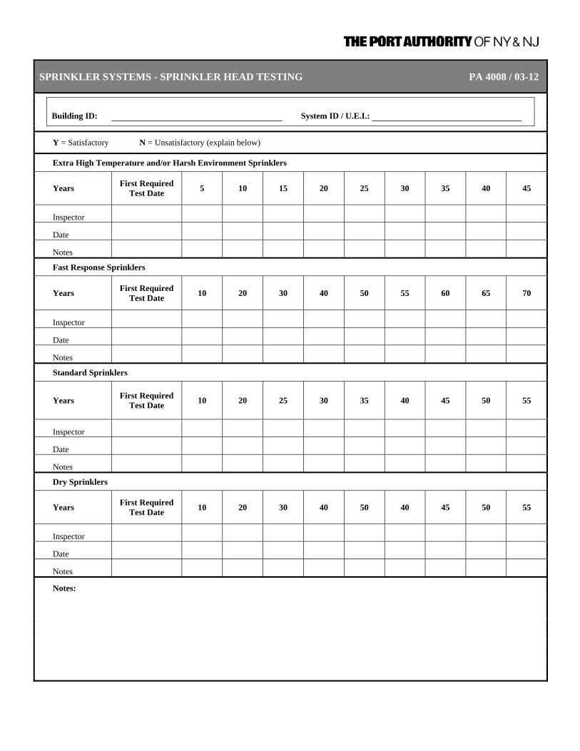
SPRINKLER SYSTEMS - SPRINKLER HEAD TESTING PA 4008 / 03-12
Building ID: System ID / U.E.I.:
Y = Satisfactory N = Unsatisfactory (explain below)
Extra High Temperature and/or Harsh Environment Sprinklers
Years First Required Test Date 5 10 15 20 25 30 35 40 45
Inspector
Date
Notes
Fast Response Sprinklers
Years First Required Test Date 10 20 30 40 50 55 60 65 70
Inspector
Date
Notes
Standard Sprinklers
Years First Required Test Date 10 20 25 30 35 40 45 50 55
Inspector
Date
Notes
Dry Sprinklers
Years First Required Test Date 10 20 30 40 50 40 45 50 55
Inspector
Date
Notes
Notes:

SPRINKLER SYSTEMS - SPRINKLER SYSTEM OBSTRUCTION INVESTIGATION PA 4009 / 03-12
Building ID: System ID / U.E.I.:
Y = Satisfactory N = Unsatisfactory (explain below)
Years First Required Test Date 5 10 15 20 25 30 35 40 45
Every 5 Years
Obstruction Investigation (every 5 years or as needed)
Inspector
Date
Notes: (List and provide details on how obstruction investigation was conducted and findings for each year conducted.)

SPRINKLER SYSTEMS - DAILY INSPECTION OF VALVE ENCLOSURE HEATING PA 4010 / 03-12
Building ID: Valve Enclosure ID:
1. Valve enclosure heating equipment for dry-pipe, pre-action, and deluge valves subject to freezing shall be inspected daily during cold weather for its ability to maintain a minimum temperature of at least 4°C (40°F).
Y = Satisfactory N = Unsatisfactory (explain below)
Date Inspector Heating Equipment (1) Notes

SPRINKLER SYSTEMS - ANNUAL MAINTENANCE PA 4011 / 03-12
Building ID: System ID / U.E.I.:
Y = Satisfactory N = Unsatisfactory (explain below) N/A = Not applicable
Date
Inspector
Control Valves Lubricate screw or yoke valve, complete close and re-open to test operation and distribute lubricant.
Alarm Valves Clean and repair internal components as necessary in accordance with manufacturer's instructions.
Dry Pipe System Clean and repair dry-pipe valves and leaks along with other appurtenances associated with air pressure drain at low points.
Pre-Action System Repair and clean pre-action or deluge valves and leaks draining at low points before freezing weather.
Deluge System Repair and clean pre-action or deluge valves and leaks draining at low points before freezing weather.
Notes:

Inspection, Testing, and Maintenance Requirements for Fire Protection and Life Safety Systems
CHAPTER 2 – STANDPIPE AND HOSE SYSTEMS 9/30/2011 | Page 2-1
CHAPTER 2 – STANDPIPE AND HOSE SYSTEMS
DEFINITIONS Automatic Standpipe System A standpipe system that is attached to a water supply
capable of supplying the system demand at all times and that requires no action other than opening a hose valve to provide water at hose connections.
Branch Line A piping system, generally in a horizontal plane, connecting
not more than one hose connection with a standpipe. Combined Standpipe and Sprinkler A system where the water piping services both 65-mm (21 2- System in.) outlets for fire department use and outlets for automatic
sprinklers. Control Valve A valve controlling flow to water-based fire protection
systems. Control valves do not include hose valves, inspector’s test valves, drain valves, trim valves for dry pipe, preaction and deluge valves, check valves, or relief valves.
Conventional Pin Rack. A hose rack where the hose is folded vertically and attached
over the pins. Dry Standpipe A standpipe system designed to have piping contain water
only when the system is being utilized. Dry Standpipe System. A system that shall be arranged as follows: (1) includes
devices to admit water to the system automatically by opening a hose valve; (2) admits water to the system through manual operation of remote control devices located at each hose station; (3) has no permanent water supply (a filled standpipe having a small water supply connection to keep the piping filled by requiring water to be pumped into the system shall be considered to be a dry standpipe).
Fire Department Connection A connection through which the fire department can pump
supplemental water into the sprinkler system, standpipe, or other system furnishing water for fire extinguishment to supplemental existing water supplies.
Hose Connection A combination of equipment provided for connection of a
hose to the standpipe system that includes a hose valve with a threaded outlet.
Horizontal Rack. A hose rack where the hose is connected to the valve, then
stack-folded horizontally to the top of the rack. Hose Reel. A circular device used to store hose.

Inspection, Testing, and Maintenance Requirements for Fire Protection and Life Safety Systems
CHAPTER 2 – STANDPIPE AND HOSE SYSTEMS 9/30/2011 | Page 2-2
Hose Station A combination of a hose rack, hose nozzle, hose, and hose
connection. Hose Valve The valve to an individual hose connection. Manual Standpipe System A standpipe system that relies exclusively on the fire
department connection to supply the system demand. Nozzle Pressure Pressure required at the inlet of a nozzle to produce the
desired water discharge characteristics. Pressure Control Valve A pilot-operated pressure reducing valve designed for the
purpose of reducing the downstream water pressure to a specific value under both flowing (residual) and nonflowing (static) conditions.
Pressure-Reducing Valve A valve designed for the purpose of reducing the
downstream water pressure under both flowing (residual) and nonflowing (static) conditions.
Pressure-Regulating Device A device designed for the purpose of reducing, regulating,
controlling, or restricting water pressure. Examples include pressure-reducing valves, pressure control valves, and pressure-restricting devices.
Pressure-Restricting Device A valve or device designed for the purpose of reducing the
downstream water pressure under flowing (residual) conditions only.
Semiautomatic Hose Rack Assembly The same as a “conventional” pin rack or hose reel except
that, after the valve is opened, a retaining device holds the hose and water until the last few feet are removed.
Semiautomatic Standpipe System A standpipe system that is attached to a water supply
capable of supplying the system demand at all times and that requires activation of a control device to provide water at hose connections.
Standpipe The vertical portion of the system piping that delivers the
water supply for hose connections, and sprinklers on combined systems, vertically from floor to floor. The term standpipe can also refer to the horizontal portion of the system piping that delivers the water supply for two or more hose connections, and sprinklers on combined systems, on a single level.

Inspection, Testing, and Maintenance Requirements for Fire Protection and Life Safety Systems
CHAPTER 2 – STANDPIPE AND HOSE SYSTEMS 9/30/2011 | Page 2-3
Standpipe System An arrangement of piping, valves, hose connections, and
allied equipment installed in a building or structure, with the hose connections located in such a manner that water can be discharged in streams or spray patterns through attached hose and nozzles, for the purpose of extinguishing a fire, thereby protecting a building or structure and its contents in addition to protecting the occupants. This is accomplished by means of connections to water supply systems or by means of pumps, tanks, and other equipment necessary to provide an adequate supply of water to the hose connections.
Wet Standpipe A standpipe system having piping containing water at all
times.
Inspection, Testing, and Maintenance Requirements for Fire Protection and Life Safety Systems
CHAPTER 2 – STANDPIPE AND HOSE SYSTEMS 9/30/2011 | Page 2-4
A. All Standpipe and Hose Systems 1. Existing Standpipe and Hose
Systems – General Information Update Annually Form PA 4013
Review General Information Form for all Fire Standpipe and Hose Systems, update as required.
2. New or Altered Standpipe
and Hose Systems General Information
Update As Required Form PA 4013
Complete General Information Form for new Fire Standpipe Systems or update General Information Form for Fire Standpipe Systems that has been altered to include repairs and/or modifications to components..
3. Control Valves Inspection Weekly Form PA 4015
12.3.2.1 All valves shall be inspected weekly.
4. Control Valves Inspection Monthly Form PA 4016
12.3.2.1.1 Valves secured with locks or supervised in accordance with applicable NFPA standards shall be permitted to be inspected monthly.
5. Control Valves Testing Annually Form PA 4018
12.3.3.1 Each control valve shall be operated annually through its full range and
returned to its normal position. 6. Control Valves Maintenance Annually Form PA 4018
12.3.4.1 The operating stems of outside screw and yoke valves shall be lubricated
annually.
12.3.4.2 The valve then shall be completely closed and reopened to test its operation and distribute the lubricant.

Inspection, Testing, and Maintenance Requirements for Fire Protection and Life Safety Systems
CHAPTER 2 – STANDPIPE AND HOSE SYSTEMS 9/30/2011 | Page 2-5
7. Pressure Reducing & Relief
Valves – Hose Connection/Hose Rack Assembly
Inspection Quarterly Form PA 4150
12.5.2 Hose Connection Pressure Reducing Valves.
12.5.2.1 All valves shall be inspected quarterly to verify the following:
(1) The handwheel is not broken or missing (2) The outlet hose threads are not damaged (3) No leaks are present (4) The reducer and the cap are not missing
12.5.3 Hose Rack Assembly Pressure Reducing Valves.
12.5.3.1 All valves shall be inspected quarterly to verify the following:
(1) The handwheel is not broken or missing (2) No leaks are present
8. Pressure Reducing & Relief
Valves – Hose Connection/Hose Rack Assembly
Testing Annually Form PA 4150
12.5.2 Hose Connection Pressure Reducing Valves.
12.5.2.3 A partial flow test adequate to move the valve from its seat shall be
conducted annually.
12.5.3 Hose Rack Assembly Pressure Reducing Valves.
12.5.3.3 A partial flow test adequate to move the valve from its seat shall be conducted annually. (1) No leaks are present
9. Pressure Reducing & Relief
Valves - Hose Connection/Hose Rack Assembly
Testing 5 Years Form PA 4150
12.5.2 Hose Connection Pressure Reducing Valves.
12.5.2.2 A full flow test shall be conducted on each valve at 5-year intervals and shall
be compared to the previous test results.
12.5.3 Hose Rack assembly Pressure Reducing Valves.
12.5.3.2 A full flow test shall be conducted on each valve at 5-year intervals and shall be compared to the previous test results.

Inspection, Testing, and Maintenance Requirements for Fire Protection and Life Safety Systems
CHAPTER 2 – STANDPIPE AND HOSE SYSTEMS 9/30/2011 | Page 2-6
10. Piping Inspection,
Maintenance Quarterly Form PA 4017
6.2.1 Components of standpipe and hose systems shall be visually inspected
quarterly or as specified in this section.
Damaged piping Repair
Control valves damaged Repair or Replace
Missing or damaged pipe support device
Repair or Replace
Damaged supervisory devices Repair or Replace
11. All Hose Connections Inspection,
MaintenanceAnnually Form PA 4018
Cap missing Replace
Fire hose connection damaged
Repair
Valve handles missing Replace
Cap gaskets missing or deteriorated
Replace
Valve leaking Close or Repair
Visible obstructions Remove
Restricting device missing Replace
Manual, semiautomatic, or dry standpipe – valve does not operate smoothly
Lubricate or Repair

Inspection, Testing, and Maintenance Requirements for Fire Protection and Life Safety Systems
CHAPTER 2 – STANDPIPE AND HOSE SYSTEMS 9/30/2011 | Page 2-7
12. Cabinet Inspection,
Maintenance Annually Form PA 4018
Check overall condition for corroded or damaged parts
Repair or replace parts; replace entire cabinet if necessary
Difficult to open Repair
Cabinet door will not open fully
Repair or move obstructions
Door glazing cracked or broken
Replace
If cabinet is break-glass type, is lock functioning properly?
Repair or replace
Glass break device missing or not attached
Replace or attach
Not properly identified as containing fire equipment
Provide identification
Visible obstructions Remove
All valves, hose, nozzles fire extinguisher, etc., easily accessible
Remove any material not related
13. Hose Inspection,
Maintenance Annually Form PA 4018
Inspect Remove and inspect the hose,
including gaskets, and rerack or rereel at intervals in accordance with NFPA 1962, Standard for the Care, Use, and Service Testing of Fire Hose Including Couplings and Nozzles
Mildew, cuts abrasions, and deterioration evident
Replace with listed, lined, jacketed hose
Coupling damaged Replace or repair
Gaskets missing or deteriorated
Replace
Inspection, Testing, and Maintenance Requirements for Fire Protection and Life Safety Systems
CHAPTER 2 – STANDPIPE AND HOSE SYSTEMS 9/30/2011 | Page 2-8
Incompatible threads on coupling
Replace or provide thread adapter
Hose not connected to hose rack nipple or valve
Connect
Hose test outdated Retest or replace in accordance with NFPA 1962, Standard for the Care, Use, And Service Testing of Fire Hose Including Couplings and Nozzles
14. Hose Nozzle Inspection,
Maintenance Annually Form PA 4018
Hose nozzle missing Replace with listed nozzle
Gasket missing or deteriorated
Replace
Obstructions Remove
Nozzle does not operate smoothly
Repair or replace
15. Hose Storage Device Inspection,
Maintenance Annually Form PA 4018
Difficult to operate Repair or replace
Damaged Repair or replace
Obstruction Remove
Hose improperly racked or rolled
Remove
Nozzle clip in place and nozzle correctly contained?
Replace if necessary
If enclosed in cabinet, will hose rack swing out at least 90 degrees?
Repair or remove any obstructions

Inspection, Testing, and Maintenance Requirements for Fire Protection and Life Safety Systems
CHAPTER 2 – STANDPIPE AND HOSE SYSTEMS 9/30/2011 | Page 2-9
16. Alarm Device Testing Quarterly Form PA 4019
12.2.7 Water-Flow Alarm. All water-flow alarms shall be tested quarterly in
accordance with the manufacturer’s instructions. 17. Alarm Device Testing Semi-Annually Form PA 4019
12.3.3.5.1 Valve supervisory switches shall be tested semiannually.
12.3.3.5.2 A distinctive signal shall indicate movement from the valve’s normal position
during either the first two revolutions of a hand wheel or when the stem of the valve has moved one-fifth of the distance from its normal position.
12.3.3.5.3 The signal shall not be restored at any valve position except the normal position.
18. Hose Testing 5 Year/
3 Year Cycle Form PA 4020
Replace or service pressure test hose 5 years after date of manufacture. Subsequently, perform service pressure test every three years thereafter.
19. Hydrostatic Test Testing 5 Years Form PA 4014
6.3.2.1 Hydrostatic tests at not less than 13.8-bar (200-psi) pressure for 2 hours, or
at 3.4-bar (50-psi) in excess of the maximum pressure, where maximum pressure is in excess of 10.3-bar (150-psi), shall be conducted every 5 years on dry standpipe systems and dry portions of wet standpipe systems.
6.3.2.2 Hydrostatic tests shall be conducted in manual standpipe systems in
accordance with 6.3.2.1 or on any system that has been modified or repaired.
6.3.2.2.1 Manual wet standpipes that are part of a combined sprinkler/standpipe
system shall not be required to be tested in accordance with 6.3.2.2.
6.3.2.3 The hydrostatic test pressure shall be measured at the low elevation point of the individual system or zone being tested. The inside standpipe piping shall show no leakage.
Inspection, Testing, and Maintenance Requirements for Fire Protection and Life Safety Systems
CHAPTER 2 – STANDPIPE AND HOSE SYSTEMS 9/30/2011 | Page 2-10
20. Flow Test Testing 5 Years Form PA 4014
6.3.1.1 A flow test shall be conducted every 5 years at the hydraulically most remote
hose connection of each zone of an automatic standpipe system to verify the water supply still provides the design pressure at the require flow.
6.3.1.2 Where a flow test of the hydraulically most remote outlet(s) is not practical,
the authority having jurisdiction shall be consulted for the appropriate location for the test.
6.3.1.3 All systems shall be flow tested and pressure tested at the requirements in
effect at the time of installation.
6.3.1.3.1 The actual test method(s) and performance criteria shall be discussed in advance with the authority having jurisdiction.
21. Main Drain Test Testing Annually Form PA 4018
12.2.6 Main Drain Test. A main drain test shall be conducted annually at each water-based fire protection system riser to determine whether there has been a change in the condition of the water supply piping and control valves. (See also 12.3.4.2).
12.3.3.4 A main drain test shall be conducted annually at each system riser and any
time the valve is closed at each system riser or feed main after the control valve has been closed to determine whether there has been a change in the condition of the water supply piping and control valves.
6.3.1.5.1 The test shall be performed at the low pipe drain for each standpipe or the
main drain test connection where the supply main enters the building (when provided).
12.3.4.2 The valve then shall be completely closed and reopened to test its operation
and distribute the lubricant. 22. Main Drain Test (For systems with
sole supply through backflow preventer and/or pressure reducing valves)
Testing Quarterly Form PA 4017
12.2.6.1 Systems where the sole water supply is through a backflow preventer and/or
pressure reducing valves, the main drain test of at least one system downstream of the device shall be conducted on a quarterly basis.
6.3.1.5.1 The test shall be performed at the low pipe drain for each standpipe or the
main drain test connection where the supply main enters the building (when provided).
12.3.4.2 The valve then shall be completely closed and reopened to test its operation
and distribute the lubricant.
Inspection, Testing, and Maintenance Requirements for Fire Protection and Life Safety Systems
CHAPTER 2 – STANDPIPE AND HOSE SYSTEMS 9/30/2011 | Page 2-11
B. Combination Sprinkler and Standpipe Systems
All components of the standpipe system are required to comply with Section A of this Chapter “All Standpipe and Hose Systems.”
All components of the sprinkler system are required to comply with Chapter 1 – Sprinkler Systems.
C. Dry Standpipe Systems
Pre-Action, Deluge, and Dry valves assemblies used in dry standpipe systems shall be inspected, tested, and maintained following requirements for these valves identified in Chapter 1 – Sprinkler Systems.
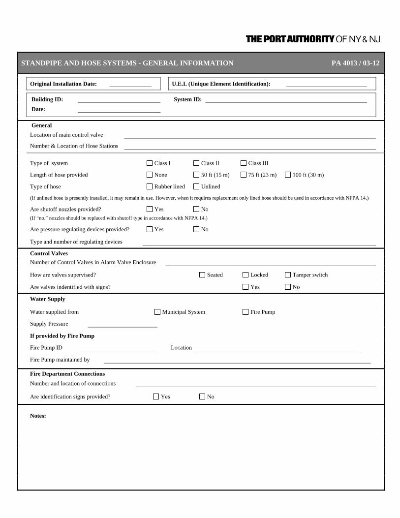
STANDPIPE AND HOSE SYSTEMS - GENERAL INFORMATION PA 4013 / 03-12
Original Installation Date: U.E.I. (Unique Element Identification):
Building ID: System ID: Date:
General
Location of main control valve
Number & Location of Hose Stations
Type of system Class I Class II Class III
Length of hose provided None 50 ft (15 m) 75 ft (23 m) 100 ft (30 m)
Type of hose Rubber lined Unlined
(If unlined hose is presently installed, it may remain in use. However, when it requires replacement only lined hose should be used in accordance with NFPA 14.)
Are shutoff nozzles provided? Yes No
(If “no,” nozzles should be replaced with shutoff type in accordance with NFPA 14.)
Are pressure regulating devices provided? Yes No
Type and number of regulating devices
Control Valves Number of Control Valves in Alarm Valve Enclosure How are valves supervised? Seated Locked Tamper switch Are valves indentified with signs? Yes No
Water Supply Water supplied from Municipal System Fire Pump
Supply Pressure
If provided by Fire Pump
Fire Pump ID Location
Fire Pump maintained by
Fire Department Connections
Number and location of connections Are identification signs provided? Yes No
Notes:

STANDPIPE AND HOSE SYSTEMS - PA 4014 / 03-12STANDPIPE HYDROSTATIC AND FLOW TEST - 5 YEARS
Building ID: System ID / U.E.I.:
Date: Inspector:
Standpipe System
Initial Test Pressure
Record the hydrostatic test pressure at the start of the test. Test pressure should be 200 psi (13.8 bar) or 50 psi (3.4 bar) above normal pressure if normal pressure exceeds 150 psi (10.3 bar).
Start Time
Record the time at the start of the test after the test pressure is reached.
End Time
Record the time at the conclusion of the hydrostatic test. The system should hold the pressure for at least 2 hours.
End Test Pressure
Record the hydrostatic pressure at the conclusion of the test.
Flow Test
Flow water from the hydraulically most remote standpipe outlet. Record: Static pressure: psi (bar)
Residual pressure: psi (bar)
Nozzle diameter: in. (cm) Pitot pressure: psi (bar)
Flow: gpm (L/min)
Notes

STANDPIPE AND HOSE SYSTEMS - WEEKLY INSPECTION PA 4015 / 03-12
Building ID: System ID / U.E.I.:
Date: Inspector:
1. If valves are sealed, note “yes” in this block. If any are not sealed, reseal and note “resealed” in this block.
2. Record any notes about the system that the inspector believes to be significant.
Date Inspector Valve(s) Sealed (1) Notes (2)

STANDPIPE AND HOSE SYSTEMS - MONTHLY INSPECTION PA 4016 / 03-12
Building ID: System ID / U.E.I.:
Date: Inspector:
1. Identify control valve location or other identification.
2. If valve is open and visually appears in good condition, note “OK” in block.
3. Record any notes about the standpipe valves that the inspector believes to be significant.
Valve ID Location Chained, Locked, Tampered Open & OK (2) Notes
Notes:

STANDPIPE AND HOSE SYSTEMS - QUARTERLY INSPECTION AND TESTS PA 4017 / 03-12
Building ID: System ID / U.E.I.:
Date: Inspector:
Y = Satisfactory N = Unsatisfactory (explain below)
Date
Inspector
Main Drain Test Performed on one standpipe system down steam of backflow preventer/pressure reducing valves. Test is performed at the low pipe drain for each standpipe or the main drain test connection where the supply main enters the building. Record the static and residual water supply pressures as indicated on the lower pressure gauge. Open the main drain and allow water flow to stabilize and then close observing return to starting static pressure.
Piping Visually inspect all standpipe and hose piping for damages to piping, valves, supports and related devices.
Pressure Reducing/Relief Valves Verify that valve handwheels are not broken or missing, no leaks, outlet hose threads are not damaged and reducer and cap are not missing.
Notes:

STANDPIPE AND HOSE SYSTEMS - PA 4018 / 03-12 ANNUAL INSPECTION, TESTING AND MAINTENANCE
Building ID: System ID / U.E.I.:
Date: Inspector:
Y = Acceptable N = Not Acceptable N/A = Not Applicable
Number of Hose Stations
Hose Cabinets - Inspection, Maintenance Inspection and maintenance includes but is not limited to check for overall condition, visible obstructions, and valves, hose, and nozzle are easily accessible.
Hose Rack/Storage Device - Inspection, Maintenance Inspection and maintenance includes but is not limited to check if difficult to operate, damaged, or obstructed.
Hose - Inspection, Maintenance Remove and rerack hose so that different parts of hose are located at bends. Check gaskets for deterioration and replace if necessary.
Hose Nozzles - Inspection, Maintenance Inspection and maintenance includes but is not limited to nozzle in place and operates smoothly.
Hose Connections Inspection and maintenance includes but is not limited to caps and valve handles are not missing and connection is not leaking.
Pressure Reducing/Relief Valves - Testing A partial flow test adequate to move the valve from its seat is required. Note if leaks are present. Number of Pressure Reducing / Relief Valves
Confirm that all pressure reducing /relief valves have been satisfactorily tested.
Control Valves Testing and maintenance involves operation of the valve through its full range and return to normal position. OS&Y valves are lubricated prior to operation through its full range. Conduct Main Drain Test Test is performed at each system riser. Record the static and residual water supply pressures as indicated on the lower pressure gauge. Open the main drain and allow water flow to stabilize and then close observing return to starting static pressure.
Notes:
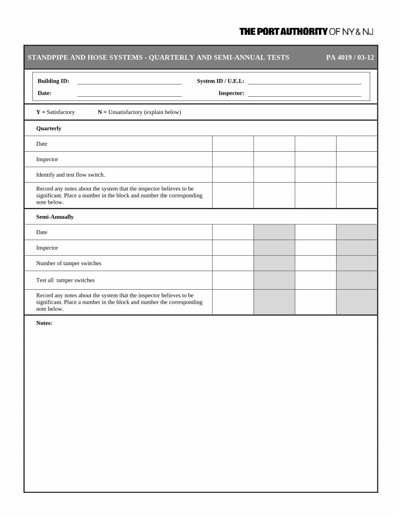
STANDPIPE AND HOSE SYSTEMS - QUARTERLY AND SEMI-ANNUAL TESTS PA 4019 / 03-12
Building ID:
System ID / U.E.I.: Date: Inspector:
Y = Satisfactory N = Unsatisfactory (explain below)
Quarterly
Date
Inspector
Identify and test flow switch.
Record any notes about the system that the inspector believes to be significant. Place a number in the block and number the corresponding note below.
Semi-Annually
Date
Inspector
Number of tamper switches
Test all tamper switches
Record any notes about the system that the inspector believes to be significant. Place a number in the block and number the corresponding note below.
Notes:

STANDPIPE AND HOSE SYSTEMS - 5-YEAR / 3-YEAR HOSE TEST PA 4020 / 03-12
Building ID: System ID / U.E.I.:
Date: Inspector:
Date of Last Test:
Y = Satisfactory N = Unsatisfactory (explain below)
Hose Station Hose Length Replaced or Tested Notes

STANDPIPE AND HOSE SYSTEMS - PA 4021 / 03-12 5-YEAR TEST PRESSURE REDUCING / RELIEF VALVES
Building ID: System ID / U.E.I.:
Date: Inspector:
Date of Last Test:
Y = Satisfactory N = Unsatisfactory (explain below) N/A = Not Applicable
1. Hose connection pressure reducing valve - full flow test compared to previous test results. 2. Hose rack assembly pressure reducing valves - full flow test compared to previous test results.
Hose Station Valve ID Pressure Reducing/Relief Valve
Flow Test Results Notes
Notes:

Inspection, Testing, and Maintenance Requirements for Fire Protection and Life Safety Systems
CHAPTER 3 – FIRE SERVICE MAINS 9/30/2011 | Page 3-1
CHAPTER 3 – FIRE SERVICE MAINS
DEFINITIONS Control Valve A valve controlling flow to water-based fire protection
systems. Control valves do not include hose valves, inspector’s test valves, drain valves, trim valves for dry pipe, preaction and deluge valves, check valves, or relief valves.
Hose House An enclosure located over or adjacent to a hydrant or other
water supply designed to contain the necessary hose nozzles, hose wrenches, gaskets, and spanners to be used in fire fighting in conjunction with and to provide aid to the local fire department.
Hydrant An exterior valved connection to a water supply system that
provides hose connections. Main Lines The piping that connects the source (pumps, receivers, etc.)
to the risers or branches, or both. (PIP) Monitor Nozzle A device specifically designed with large, clear waterways to
provide a powerful, far-reaching stream for the protection of large amounts of combustible materials, aircraft, tank farms, and any other special hazard locations where large amounts of water need to be instantly available without the delay of laying hose lines. The nozzle is normally fitted with one of three interchangeable tips that measure 11 2 in., 13 4 in., and 2 in. (40 mm, 45 mm, and 50 mm) in diameter.
Monitor Nozzle Hydrant A hydrant equipped with a monitor nozzle capable of
delivering more than 250 gpm (946 L/min). Private Fire Service Main Private fire service main, as used in this standard, is that
pipe and its appurtenances on private property (1) between a source of water and the base of the system riser for water-based fire protection systems, (2) between a source of water and inlets to foam-making systems, (3) between a source of water and the base elbow of private hydrants or monitor nozzles, and (4) used as fire pump suction and discharge piping, (5) beginning at the inlet side of the check valve on a gravity or pressure tank.

Inspection, Testing, and Maintenance Requirements for Fire Protection and Life Safety Systems
CHAPTER 3 – FIRE SERVICE MAINS 9/30/2011 | Page 3-2
Private Fire Service Main The pipe and its appurtenances located on private property between a source of water and the base of the riser (i.e., the flange, the flange and spigot piece, or the base tee) for automatic sprinkler systems, open sprinkler systems, water spray fixed systems, standpipe systems, inlets to foam-making systems, or the base elbow of private hydrants or monitor nozzles. Where connected to a public water system, the private service main begins at a point designated by the public water utility, usually at a manually operated valve near the property line. Where connected to fire pumps, the main begins at the fire-protection-system side of the pump discharge valve. Where connected to a gravity or pressure tank, the main begins at the inlet side of the tank’s check valve. Private fire service mains can include supply and distribution piping installed above ground, in trenches, and inside or outside of buildings. The provisions of this definition also apply to pipeline strainers.
Strainer A device capable of removing from the water all solids of
sufficient size that are obstructing water spray nozzles. Fire Hydrant A valved connection on a water main for the purpose of
supplying water to fire hose or other fire protection apparatus.
Dry Barrel Hydrant (Frostproof This is the most common type of hydrant; it has a control Hydrant) valve below the frost line between the footpiece and the
barrel. A drain is located at the bottom of the barrel above the control valve seat for proper drainage after operation.
Monitor Nozzle Hydrant A hydrant equipped with a monitor nozzle capable of
delivering more than 946 L/min (250 gpm). Wall Hydrant A hydrant mounted on the outside of a wall of a building, fed
from interior piping, and equipped with control valves located inside the building that normally are key-operated from the building’s exterior.
Water Supply Asource of water that provides the flows (L/min) and
pressures (bar) required by the water-based fire protection system.
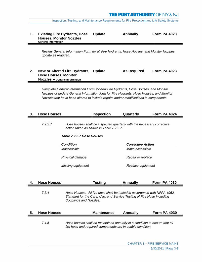
Inspection, Testing, and Maintenance Requirements for Fire Protection and Life Safety Systems
CHAPTER 3 – FIRE SERVICE MAINS 9/30/2011 | Page 3-3
1. Existing Fire Hydrants, Hose
Houses, Monitor Nozzles General Information
Update Annually Form PA 4023
Review General Information Form for all Fire Hydrants, Hose Houses, and Monitor Nozzles, update as required.
2. New or Altered Fire Hydrants,
Hose Houses, Monitor Nozzles – General Information
Update As Required Form PA 4023
Complete General Information Form for new Fire Hydrants, Hose Houses, and Monitor Nozzles or update General Information form for Fire Hydrants, Hose Houses, and Monitor Nozzles that have been altered to include repairs and/or modifications to components.
3. Hose Houses Inspection Quarterly Form PA 4024
7.2.2.7 Hose houses shall be inspected quarterly with the necessary corrective
action taken as shown in Table 7.2.2.7.
Table 7.2.2.7 Hose Houses
Condition Corrective Action Inaccessible Make accessible
Physical damage Repair or replace
Missing equipment Replace equipment
4. Hose Houses Testing Annually Form PA 4030
7.3.4 Hose Houses. All fire hose shall be tested in accordance with NFPA 1962,
Standard for the Care, Use, and Service Testing of Fire Hose Including Couplings and Nozzles.
5. Hose Houses Maintenance Annually Form PA 4030
7.4.5 Hose houses shall be maintained annually in a condition to ensure that all
fire hose and required components are in usable condition.
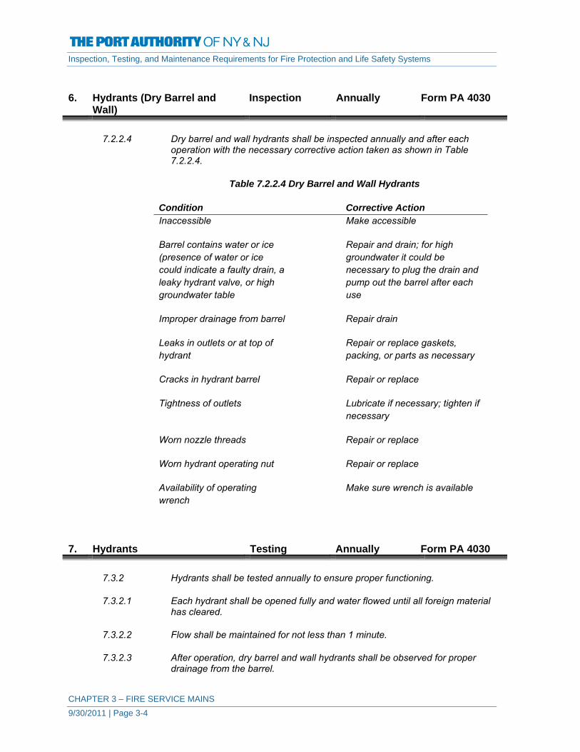
Inspection, Testing, and Maintenance Requirements for Fire Protection and Life Safety Systems
CHAPTER 3 – FIRE SERVICE MAINS 9/30/2011 | Page 3-4
6. Hydrants (Dry Barrel and
Wall) Inspection Annually Form PA 4030
7.2.2.4 Dry barrel and wall hydrants shall be inspected annually and after each
operation with the necessary corrective action taken as shown in Table 7.2.2.4.
Table 7.2.2.4 Dry Barrel and Wall Hydrants
Condition Corrective Action Inaccessible Make accessible
Barrel contains water or ice (presence of water or ice could indicate a faulty drain, a leaky hydrant valve, or high groundwater table
Repair and drain; for high groundwater it could be necessary to plug the drain and pump out the barrel after each use
Improper drainage from barrel Repair drain
Leaks in outlets or at top of hydrant
Repair or replace gaskets, packing, or parts as necessary
Cracks in hydrant barrel Repair or replace
Tightness of outlets Lubricate if necessary; tighten if necessary
Worn nozzle threads Repair or replace
Worn hydrant operating nut Repair or replace
Availability of operating wrench
Make sure wrench is available
7. Hydrants Testing Annually Form PA 4030
7.3.2 Hydrants shall be tested annually to ensure proper functioning.
7.3.2.1 Each hydrant shall be opened fully and water flowed until all foreign material
has cleared.
7.3.2.2 Flow shall be maintained for not less than 1 minute.
7.3.2.3 After operation, dry barrel and wall hydrants shall be observed for proper drainage from the barrel.

Inspection, Testing, and Maintenance Requirements for Fire Protection and Life Safety Systems
CHAPTER 3 – FIRE SERVICE MAINS 9/30/2011 | Page 3-5
7.3.2.4 Full drainage shall take no longer than 60 minutes.
8. Hydrants Maintenance Annually Form PA 4030
7.4.3.1 Hydrants shall be lubricated annually to ensure that all stems, caps, plugs
and threads are in proper operating condition.
7.4.3.2 Hydrants shall be kept free of snow, ice, or other materials and protected against mechanical damage so that free access is ensured.
9. Monitor Nozzles Inspection Semi-Annually Form PA 4025
7.2.2.6 Monitor nozzles shall be inspected semiannually with the necessary corrective action taken as shown in Table 7.2.2.6.
Table 7.2.2.6 Monitor Nozzles
Condition Corrective Action Leakage Repair
Physical damage Repair or replace
Corrosion Clean or replace, and lubricate or protect as necessary
10. Monitor Nozzles
(Range & Operation) Testing Annually Form PA 4030
7.3.3.1 Monitor nozzles that are mounted on hydrants shall be tested as specified in
7.3.2.
7.3.2.1 Each hydrant shall be opened fully and water flowed until all foreign material has cleared.
7.3.2.2 Flow shall be maintained for not less than 1 minute.
7.3.3.2 All monitor nozzles shall be oscillated and moved throughout their full range
annually to ensure proper operability.
A monitor nozzle may be a fixed position device or a directional device capable of being manually or automatically rotated either from side to side or up and down. Paragraph 7.3.3.2 addresses the fact that it is necessary to ensure that the device maintains full movement in all directions.
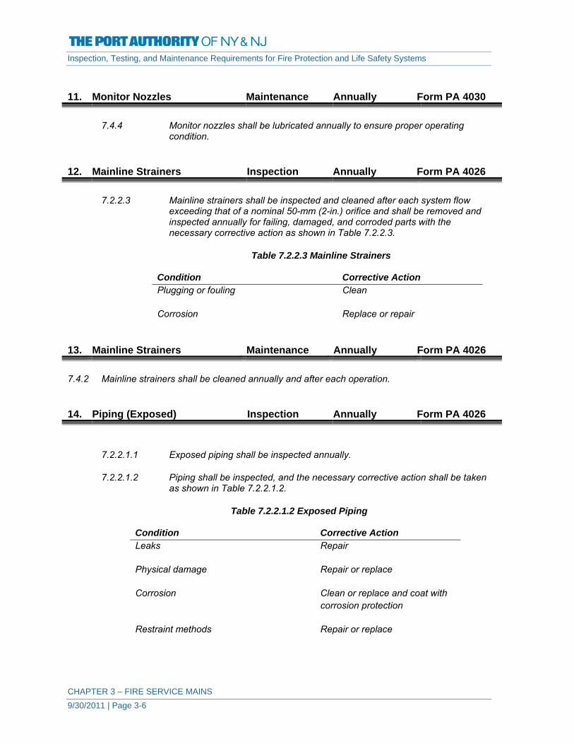
Inspection, Testing, and Maintenance Requirements for Fire Protection and Life Safety Systems
CHAPTER 3 – FIRE SERVICE MAINS 9/30/2011 | Page 3-6
11. Monitor Nozzles Maintenance Annually Form PA 4030
7.4.4 Monitor nozzles shall be lubricated annually to ensure proper operating
condition. 12. Mainline Strainers Inspection Annually Form PA 4026
7.2.2.3 Mainline strainers shall be inspected and cleaned after each system flow
exceeding that of a nominal 50-mm (2-in.) orifice and shall be removed and inspected annually for failing, damaged, and corroded parts with the necessary corrective action as shown in Table 7.2.2.3.
Table 7.2.2.3 Mainline Strainers
Condition Corrective Action Plugging or fouling Clean
Corrosion Replace or repair
13. Mainline Strainers Maintenance Annually Form PA 4026
7.4.2 Mainline strainers shall be cleaned annually and after each operation. 14. Piping (Exposed) Inspection Annually Form PA 4026
7.2.2.1.1 Exposed piping shall be inspected annually.
7.2.2.1.2 Piping shall be inspected, and the necessary corrective action shall be taken as shown in Table 7.2.2.1.2.
Table 7.2.2.1.2 Exposed Piping
Condition Corrective Action Leaks Repair
Physical damage Repair or replace
Corrosion Clean or replace and coat with corrosion protection
Restraint methods Repair or replace

Inspection, Testing, and Maintenance Requirements for Fire Protection and Life Safety Systems
CHAPTER 3 – FIRE SERVICE MAINS 9/30/2011 | Page 3-7
7.2.2.1.3 Piping installed in areas that are inaccessible for safety considerations due to process operations shall be inspected during each scheduled shutdown.
15. Piping (Underground) Inspection 5 Years Form PA 4027
7.2.2.2 Underground Piping. Generally, underground piping cannot be inspected on a routine basis. However, flow testing can reveal the condition of underground piping and shall be conducted in accordance with Number 16 below.
16. Piping (Exposed and
Underground) Testing 5 Years Forms PA 4027
& PA 4028
7.3.1 Underground and exposed piping shall be flow tested to determine the
internal condition of the piping at minimum 5-year intervals.
7.3.1.1 Flow tests shall be made at flow representative of those expected during a fire for the purpose of comparing the friction loss characteristics of the pipe with those expected for the particular type of pipe involved, with due consideration given to the age of the pipe and to the results of previous flow tests.
7.3.1.2 Any flow test results that indicate deterioration of available water flow and
pressure shall be investigated to the complete satisfaction of the authority having jurisdiction to ensure that the required flow and pressure are available for fire protection.
7.3.1.3 Where underground piping supplies individual fire sprinkler, standpipe, water
spray, or foam-water sprinkler systems and there are no means to conduct full flow tests, tests generating the maximum available flows shall be permitted.
17. Piping Repair Record Maintenance As Necessary Form PA 4029
Complete Form G for fire service main piping that has been altered, repaired, or replaced.

FIRE SERVICE MAINS - FIRE HYDRANTS, HOSE HOUSES, PA 4023 / 03-12 MONITOR NOZZLES - GENERAL INFORMATION
Original Installation Date: U.E.I. (Unique Element Identification) :
Building ID: System ID:
Date: Description of Protected Area:
Fire Hydrants
Hydrant ID:
Hydrant Manufacturer and Model No.:
Number and Size of Outlets
Thread Type
Operating Direction and Number of Turns
Normal Operating Pressure:
Location of Shutoff Valve
Other Hydrant Information - Impact Protection, Wall Hydrant, etc.
Hose Houses
Hose House ID
Type of Hose, Length , and Size
Thread Type
Other Information
Monitor Nozzles
Nozzle Manufacturer and Model No.:
Thread Type Size of Nozzle
Other Information - Oscillating, Automatic/Manual, etc.
Notes:

FIRE SERVICE MAINS - FIRE HYDRANTS, HOSE HOUSES, PA 4024 / 03-12MONITOR NOZZLES - QUARTERLY INSPECTION
Building ID: System ID / U.E.I.:
Date: Inspector:
Y = Satisfactory N = Unsatisfactory (explain below)
Check hose houses to make sure they are accessible, not damaged, and all equipment is present.
Date
Inspector
Hose House ID / U.E.I.
Notes:

FIRE SERVICE MAINS - FIRE HYDRANTS, HOSE HOUSES, PA 4025 / 03-12 MONITOR NOZZLES - SEMI-ANNUAL INSPECTION
Building ID: System ID:
Y = Satisfactory N = Unsatisfactory (explain below)
Date
Inspector
Monitor Nozzle ID / U.E.I. Leakage Physical Damage Corrosion
Notes:

FIRE SERVICE MAINS - FIRE HYDRANTS, HOSE HOUSES, PA 4026 / 03-12MONITOR NOZZLES - ANNUAL INSPECTION & MAINTENANCE
Building ID: System ID / U.E.I.:
Date: Inspector:
Y = Satisfactory N = Unsatisfactory (explain below)
Main Line Strainers
Inspect and clean annually for failings, damage and corrosion.
Exposed Piping
Physical Damage
Corrosion
Restraint Methods
Notes:

FIRE SERVICE MAINS - FIRE HYDRANTS, HOSE HOUSES, MONITOR NOZZLES - PA 4027 / 03-125-YEAR FLOW TEST & UNDERGROUND PIPING INSPECTION
Building ID: System ID / U.E.I.: Date: Inspector:
Water Distribution Systems
Annual test is accomplished during fire hydrant annual tests. For each test, record the following:
Residual hydrant location :
Flow hydrant location:
Static pressure (residual hydrant): psi (bar)
Residual pressure (residual hydrant): psi (bar)
Pitot pressure (flow hydrant): psi (bar)
Nozzle size (flow hydrant): in. (mm)
Nozzle coefficient (flow hydrant): 0.9; other
Available water flow: gpm (L/min) at psi (bar)
Y = Satisfactory N = Unsatisfactory (explain below)
Condition of underground piping
Notes:

Date: Location:
FIRE SERVICE MAINS - FIRE HYDRANTS, HOSE HOUSES, MONITOR NOZZLES - FLOW AND PRESSURE RECORD PA 4028 / 02-12
140
130
100
90
120
110
N 1.85
in. (
psi)
150
9 10Flow - gal. per min (gpm)
12 13 14 15 16 171 2 3 4 5 6 7 8 11 18 19 20
20
10
40
30
60
50
80
70
Pres
sure
- lb
. per
sq. i

FIRE SERVICE MAINS - FIRE HYDRANTS, HOSE HOUSES, PA 4029 / 03-12 MONITOR NOZZLES - PIPING REPAIR RECORD
Building ID: System ID / U.E.I.:
Y = Satisfactory N = Unsatisfactory (explain below)
Description of Fire Service Main (Size, Pipe Material, Valves, etc.):
Description of Work - Include Details:
Date Work Performed:
Work Performed by Contractor:
Facility:
List of Control Valves Operated:
Confirm that all control valves have been returned to normal condition:
Hydrostatic Test:
Flushing:
Notes:
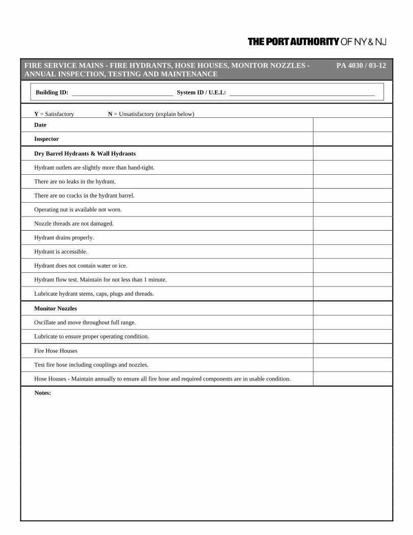
FIRE SERVICE MAINS - FIRE HYDRANTS, HOSE HOUSES, MONITOR NOZZLES - PA 4030 / 03-12 ANNUAL INSPECTION, TESTING AND MAINTENANCE
Building ID: System ID / U.E.I.:
Y = Satisfactory N = Unsatisfactory (explain below)
Date
Inspector
Dry Barrel Hydrants & Wall Hydrants
Hydrant outlets are slightly more than hand-tight.
There are no leaks in the hydrant.
There are no cracks in the hydrant barrel.
Operating nut is available not worn.
Nozzle threads are not damaged.
Hydrant drains properly.
Hydrant is accessible.
Hydrant does not contain water or ice.
Hydrant flow test. Maintain for not less than 1 minute.
Lubricate hydrant stems, caps, plugs and threads.
Monitor Nozzles
Oscillate and move throughout full range.
Lubricate to ensure proper operating condition.
Fire Hose Houses
Test fire hose including couplings and nozzles.
Hose Houses - Maintain annually to ensure all fire hose and required components are in usable condition.
Notes:

Inspection, Testing, and Maintenance Requirements for Fire Protection and Life Safety Systems
CHAPTER 4 – FIRE PUMP SYSTEMS 9/30/2011 | Page 4-1
CHAPTER 4 – FIRE PUMP SYSTEMS
DEFINITIONS Automatic Transfer Switch Self-acting equipment for transferring one or more load
conductor connections from one power source to another. Centrifugal Pump A pump in which the pressure is developed principally by the
action of centrifugal force. Control Valve A valve controlling flow to water-based fire protection
systems. Control valves do not include hose valves, inspector’s test valves, drain valves, trim valves for dry pipe, preaction and deluge valves, check valves, or relief valves.
Diesel Engine An internal combustion engine in which the fuel is ignited
entirely by the heat resulting from the compression of the air supplied for combustion. The oil-diesel engine, which operates on fuel oil injected after compression is practically completed, is the type usually used as a fire pump driver.
Dump Valve An automatic valve installed on the discharge side of a
positive displacement pump to relieve pressure prior to the pump driver reaching operating speed.
Engine Speed The speed indicated on the engine nameplate. Fire Pump A pump supplying water at the flow and pressure required by
water-based fire protection systems. Fire Pump Controller A group of devices that serve to govern, in some
predetermined manner, the starting and stopping of the fire pump driver and to monitor and signal the status and condition of the fire pump unit.
Fire Pump Unit An assembled unit consisting of a fire pump, driver,
controller, and accessories. Head A quantity used to express a form (or combination of forms)
of the energy content of water per unit weight of the water referred to any arbitrary datum.
Horizontal Pump A pump with the shaft normally in a horizontal position. Horizontal Split-Case Pump A centrifugal pump characterized by a housing that is split
parallel to the shaft.

Inspection, Testing, and Maintenance Requirements for Fire Protection and Life Safety Systems
CHAPTER 4 – FIRE PUMP SYSTEMS 9/30/2011 | Page 4-2
Isolating Switch A switch intended for isolating an electric circuit from its
source of power. It has no interrupting rating, and it is intended to be operated only after the circuit has been opened by some other means.
Loss of Phase The loss of one or more, but not all, phases of the polyphase
power source. Low Suction Throttling Valve A pilot-operated valve installed in discharge piping that
maintains positive pressure in the suction piping, while monitoring pressure in the suction piping through a sensing line.
Manual Transfer Switch A switch operated by direct manpower for transferring one or
more load conductor connections from one power source to another.
Motor Speed The speed indicated on the motor nameplate. Positive Displacement Pump A pump that is characterized by a method of producing flow
by capturing a specific volume of fluid per pump revolution and reducing the fluid void by a mechanical means to displace the pumping fluid.
Pressure Control Valve A pilot-operated pressure reducing valve designed for the
purpose of reducing the downstream water pressure to a specific value under both flowing (residual) and nonflowing (static) conditions.
Pressure-Reducing Valve A valve designed for the purpose of reducing the
downstream water pressure under both flowing (residual) and nonflowing (static) conditions.
Pressure-Regulating Device A device designed for the purpose of reducing, regulating,
controlling, or restricting water pressure. Examples include pressure-reducing valves, pressure control valves, and pressure-restricting devices.
Rated Speed The speed for which the fire pump is listed and appears on
the fire pump nameplate. Relief Valve A device that allows the diversion of liquid to limit excess
pressure in a system. Unloader Valve A valve that is designed to relieve excess flow below pump
capacity at set pump pressure. Variable Speed Pressure Limiting A speed control system used to limit the total discharge Control pressure by reducing the pump driver speed from rated
speed.

Inspection, Testing, and Maintenance Requirements for Fire Protection and Life Safety Systems
CHAPTER 4 – FIRE PUMP SYSTEMS 9/30/2011 | Page 4-3
Vertical Lineshaft Turbine Pump A vertical shaft centrifugal pump with rotating impeller or impellers and with discharge from the pumping element coaxial with the shaft. The pumping element is suspended by the conductor system, which encloses a system of vertical shafting used to transmit power to the impellers, the prime mover being external to the flow stream.
A. ALL FIRE PUMPS 1. Existing Fire Pumps
General Information Update Annually Form PA 4031
Review General Information Form for all Fire Pump Systems, update as required.
2. New or Altered Fire Pumps
General Information Update As Required Form PA 4031
Complete General Information Form for new Fire Pump Systems or update General Information form for Fire Pump Systems that have been altered to include repairs and/or modifications to components.
3. Pump House, Heating
Ventilating Louvers Inspection Weekly Form PA 4032
8.2.2 (1) Pump House Conditions.
a) Heat is adequate, not less than 40° or 70°F for pump rooms with diesel pumps without engine heaters.
b) Ventilation louvers are free to operate. 4. Fire Pump System Inspection Weekly Form PA 4032
8.2.2 (2) Pump System Conditions.
a) Pump suction and discharge and bypass valves are fully open b) Piping is free of leaks c) Suction line pressure reading normal d) System line pressure gauge reading is normal e) Suction reservoir is full f) Wet pit suction screens are unobstructed and in place

Inspection, Testing, and Maintenance Requirements for Fire Protection and Life Safety Systems
CHAPTER 4 – FIRE PUMP SYSTEMS 9/30/2011 | Page 4-4
5. Pump Operation
Flow Condition Testing Annually Forms PA 4042
and PA 4043
8.3.3.1 An annual test of each pump assembly shall be conducted under minimum,
rated, and peak flows of the fire pump by controlling the quantity of water discharged through approved test devices.
8.3.3.1.2.1 Use of the Pump Discharge Via the Hose Streams. Pump suction and
discharge pressures and the flow measurements of each hose stream shall determine the total pump output. Care shall be taken to prevent water damage by verifying there is adequate drainage for the high-pressure water discharge from hoses.
8.3.3.1.2.2 Use of the Pump Discharge Via the Bypass Flowmeter to Drain or Suction
the Reservoir. Pump suction and discharge pressures and the flowmeter measurements shall determine to total pump output.
8.3.3.1.2.3 Use of the Pump Discharge Via the Bypass Flowmeter to Pump Suction
(Closed-Loop Metering). Pump suction and discharge pressures and the flowmeter measurements shall determine the total pump output.
8.3.3.1.3 Where the annual test is conducted periodically in accordance with
8.3.3.1.2.3, a test shall be conducted every 3 years in accordance with 8.3.3.1.2.1 or 8.3.3.1.2.2 in lieu of the method described in 8.3.3.1.2.3.
8.3.3.1.4 Where 8.3.3.1.2.2 or 8.3.3.1.2.3 is used, the flow meter shall be adjusted
immediately prior to conducting the test in accordance with the manufacturer’s instructions. If the test results are not consistent with the previous annual test, 8.3.3.1.2.1 shall be used. If testing in accordance with 8.3.3.1.2.1 is not possible, a flowmeter calibration shall be performed and the test shall be repeated.
8.3.3.2 The pertinent visual observations, measurements, and adjustments specified
in the following checklists shall be conducted annually while the pump is running and flowing water under the specified output condition:
1) At no-flow condition (churn):
a) Check the circulation relief valve for operation to discharge water b) Check the pressure relief valve (if installed) for proper operation c) Continue the test for 1⁄2 hour
2) At each flow condition:
a) Record the electric motor voltage and current (all lines) b) Record the pump speed in rpm c) Record the simultaneous (approximately) readings of pump suction
and discharge pressures and pump discharge flow
8.3.3.3 For installations having a pressure relief valve, the operation of the relief valve shall be closely observed during each flow condition to determine if the pump discharge pressure exceeds the normal operating pressure of the system components.

Inspection, Testing, and Maintenance Requirements for Fire Protection and Life Safety Systems
CHAPTER 4 – FIRE PUMP SYSTEMS 9/30/2011 | Page 4-5
8.3.3.3.1 The pressure relief valve shall also be observed during each flow condition to determine if the pressure relief valve closes at the proper pressure.
8.3.3.3.2 A pressure relief valve that is open during a flow condition will affect test
results.
8.3.3.7 Suction Screens. After the water-flow portions of the annual test or fire protection system activations, the suction screens shall be inspected and cleared of any debris or obstructions.
6. Fire Pump Maintenance Maintenance As Required Forms PA 4032,
4033, 4035, 4036, 4037, 4038, 4039, 4041, 4043
8.5.1 A preventive maintenance program shall be established on all components of
the pump assembly in accordance with the manufacturer’s recommendations.
8.5.2 Records shall be maintained on all work performed on the pump, driver,
controller, and auxiliary equipment.
8.5.3 In the absence of manufacturer’s recommendations for preventive maintenance, Table 8.5.3 shall be used for alternative requirements.
8.5.4 The preventive maintenance program shall be initiated immediately after the
pump assembly has passed acceptance tests.

Inspection, Testing, and Maintenance Requirements for Fire Protection and Life Safety Systems
CHAPTER 4 – FIRE PUMP SYSTEMS 9/30/2011 | Page 4-6
Visual Inspection
Check Change Clean Test Frequency Form
A.
1. Lubricate pump bearings X Annually 4039
2. Check pump shaft end play X Annually 4036
3. X X Annually (change or recalibrate when 5% out of calibration)
4036
4. Check pump coupling alignment X Annually 4037
5. Wet pit suction screens X X After each pump operation
4039
B.
1. Lubricate coupling X Annually 4039
2. Lubricate right‐angle gear drive X Annually 4039
C.
1. X Monthly 4034, 4041, 4043
2. X Annually 4034
3. X Semi‐annually 4041
4. X X Annually 4042
5. X Annually 4039
6. X Annually 4039
7. X Annually 4039
8. X Annually 4039
D.
1.
(a) Tank level X X Weekly 4033
(b) Tank float switch X X Weekly 4033
(c) Solenoid valve operation X X Weekly 4033
(d)X Quarterly 4038
(e) Water and foreign material in tank X Annually 4039
(f) Water in system X X Weekly 4033
(g) Flexible hoses and connectors X Weekly 4033
(h)X X Annually 4036
(i) Piping X Annually 4036
Grease motor bearings
Diesel Engine System
Fuel
Strainer, filter, or dirt leg, or combination thereof
Table 8.5.3 Fire Pump Maintenance ‐ Alternative Requirements
Tank vents and overflow pipingunobstructed
Calibrate pressure switch settings
Complete as Applicable
Pump System
Check accuracy of pressure gauges and sensor gauges
Mechanical Transmission
Tighten electrical connections as necessary
Lubricate mechanical moving parts
Electrical System
Exercise isolating switch and circuit breaker
Trip circuit breaker (if mechanism provided)
Operate manual starting means (electrical)
Inspect and operate emergency manual

Inspection, Testing, and Maintenance Requirements for Fire Protection and Life Safety Systems
CHAPTER 4 – FIRE PUMP SYSTEMS 9/30/2011 | Page 4-7
Visual
InspectionCheck Change Clean Test Frequency Form
2. Lubrication System
(a) Oil level X X Weekly 4033
(b) Oil change X 50 hours or Annually
4039
(c) Oil filter(s) X 50 hours or Annually
4039
(d) Lube oil heater X Weekly 4033
(e) Crankcase breather X X X Quarterly 4038
3. Cooling System
(a) Level X X Weekly 4033
(b) Antifreeze protection level X Semi‐annually 4041
(c) Antifreeze X Annually 4039
(d) Adequate cooling water to heat exchanger X Weekly 4033
(e) Rod out heat exchanger X Annually 4039
(f) Water pump(s) X Weekly 4033
(g)X X Weekly 4033
(h) Jacket water heater X Weekly 4033
(i)X X Annually 4039
(j) Water strainer X Quarterly 4038
4. Exhaust System(a) Leakage X X Weekly 4033
(b) Drain condensate trap X Weekly 4033
(c) Insulation and fire hazards X Quarterly 4038
(d) Excessive back pressure X Annually 4043
(e) Exhaust system hanger and supports X Annually 4037
(f) Flexible exhaust section X Semi‐annually 4038
5. Battery System(a) Electrolyte level X Weekly 4033
(b) Terminals clean and tight X X Quarterly 4035
(c) X X Monthly 4034
(d) Specific gravity or state of charge X Monthly 4034
(e) Charger and charge rate X Monthly 4034
(f) Equalize charge X Monthly 4034
6. Electrical System(a) General inspection X Weekly 4033
(b) X Annually 4039
(c) Wire chafing where subject to movement X X Quarterly 4035
(d) Operation of safeties and alarms X X Semi‐annually 4038
(e) Boxes, panels, and cabinets X Semi‐annually 4038
(f) Circuit breakers or fuses X X Monthly 4034
(g) Circuit breakers or fuses X Biennially 4038
Table 8.5.3 Fire Pump Maintenance ‐ Alternative Requirements (Continued)
Inspect ductwork, clean louvers (combustion air)
Remove corrosion, case exterior clean and dry
Tighten control & power wiring
Complete as Applicable
Condition of Flexible water hoses and connections

Inspection, Testing, and Maintenance Requirements for Fire Protection and Life Safety Systems
CHAPTER 4 – FIRE PUMP SYSTEMS 9/30/2011 | Page 4-8
B. ELECTRIC DRIVEN FIRE PUMPS In addition to A above, the following is required for electric driven fire pumps. 1. Pump Operation No Flow Testing Weekly Form PA 4040
8.3.1 A weekly test of fire pump assemblies shall be conducted without flowing
water.
8.3.1.1 This test shall be conducted by starting the pump automatically.
8.3.1.2 The electric pump shall run a minimum of 10 minutes.
8.3.1.4 A valve installed to open as a safety feature shall be permitted to discharge water.
8.3.1.5 The automatic weekly test times shall be permitted to be substituted for the
starting procedure.
8.3.2.2 The pertinent visual observations or adjustments specified in the following checklists shall be conducted while the pump is running.
1) Pump System Procedure:
a) Record the system suction and discharge pressure gauge readings. b) Check pump packing glands for flight discharge c) Adjust gland nuts, if necessary d) Check for unusual noise or vibration e) Check packing boxes, bearings or pump casing for overheating f) Record the pump starting pressure
2) Electrical System Procedure:
a) Observe the time for motor to accelerate to full speed b) Record the time controller is on first step (for reduced voltage or
reduce current) c) Record the time pump runs after starting (for automatic stop
controller).

Inspection, Testing, and Maintenance Requirements for Fire Protection and Life Safety Systems
CHAPTER 4 – FIRE PUMP SYSTEMS 9/30/2011 | Page 4-9
2. Pump Operation Flow
Condition Testing Annually Forms PA 4042,
PA 4043
In addition to Number A. 5., perform the following:
8.3.3.4 For installations having an automatic transfer switch, the following test shall be performed to ensure that the overcurrent protective devices (i.e., fuses or circuit breakers) do not open: 1) Simulate a power failure condition while the pump is operating at
peak load 2) Verify that the transfer switch transfers power to the alternate power
source 3) Verify that the pump continues to perform at peak load 4) Remove the power failure condition and verify that after a time
delay, the pump is reconnected to the normal power source C. DIESEL DRIVEN FIRE PUMPS In addition to A above, the following is required for diesel driven fire pumps. 1. Diesel Engine System Inspection Weekly Form PA 4033
a) Fuel tank is two-thirds full b) Controller selector switch is in auto position c) Battery (2) voltage readings are normal d) Battery (2) charging current readings are normal e) Battery (2) pilot lights are on or battery failure (2) pilot lights are off f) All alarm pilot lights are off g) Engine running time meter is reading h) Oil level in right angle gear drive is normal i) Crank case oil level is normal j) Cooling water level is normal k) Electrolyte level in batteries is normal l) Battery terminals are free of corrosion m) Water-jacket heater is operating
2. Pump Operation No Flow Testing Weekly Form PA 4040
8.3.1 A weekly test of fire pump assemblies shall be conducted without flowing
water. 8.3.1.1 This test shall be conducted by starting the pump automatically.
8.3.1.3 The diesel pump shall run a minimum of 30 minutes.

Inspection, Testing, and Maintenance Requirements for Fire Protection and Life Safety Systems
CHAPTER 4 – FIRE PUMP SYSTEMS 9/30/2011 | Page 4-10
8.3.1.4 A valve installed to open as a safety feature shall be permitted to discharge water.
8.3.1.5 The automatic weekly test times shall be permitted to be substituted for the
starting procedure.
8.3.2.2 The pertinent visual observations or adjustments specified in the following checklists shall be conducted while the pump is running.
1) Pump System Procedure:
a) Record the system suction and discharge pressure gauge readings b) Check the pump packing glands for slight discharge c) Adjust gland nuts if necessary d) Check for unusual noise or vibration e) Check packing boxes, bearings, or pump casing for overheating f) Record the pump starting pressure
2) Diesel Engine System Procedure:
a) Observe the time for engine to crank b) Observe the time for engine to reach running speed c) Observe the engine oil pressure gauge, speed indicator water, and
oil temperature indicators periodically while engine is running d) Record any abnormalities e) Check the heat exchanger for cooling water flow
D. CONTROLLERS 1. Electrical System Condition Inspection Annually Form PA 4036
a) Controller pilot light (power on ) is illuminated b) Transfer switch normal pilot light is illuminated c) Isolating switch is closed – Standby (emergency) source d) Reverse phase alarm pilot light is off or normal phase rotating pilot
light is on e) Oil level in vertical motor sight is normal

FIRE PUMP SYSTEMS - GENERAL INFORMATION PA 4031 / 03-12
Original Installation Date: U.E.I. (Unique Element Identification) :
Dates Reviewed: Fire Pump Identification
Location:
Pump Provides Supply to:
Fire Pump Information Rating GPM: Head (psi): Speed (rpm):
Manufacturer: Serial Number: Impeller Diameter (in):
Fire Pump Driver Manufacturer: Serial Number: Speed (rpm): Horse Power: Electric Volts: Amps at Full Load: Phase: Cycle Diesel Number of Cylinders: Diesel Fuel Supply Amount (gal):
Fire Pump Controller Manufacturer: Serial Number:
Cut in Pressure (psi): Cut out Pressure (psi): Auto/Manual Start: Auto/Manual Stop:
Emergency Power Source: Transfer Switch Manufacturer: Serial Number:
Jockey Pump Manufacturer: Serial Number: Cut in Pressure (psi): Cut out Pressure (psi):
Water Supply Source City Supply (Name of Utility) Storage Tank (No. & Size)
Main Relief Valve Yes No Manufacturer: Size: Pressure Setting for Relief:
Notes:

FIRE PUMP SYSTEMS - WEEKLY INSPECTION - ELECTRIC MOTOR FIRE PUMPS PA 4032 / 03-12
Building ID: Pump ID / U.E.I.: Year:
Y = Satisfactory N = Unsatisfactory (explain on reverse) N/A = Not applicable
Date
Inspector
Heat in pump room is not less than 40°F.
Pump suction, discharge, and bypass valves are open.
No piping or hoses leak.
Fire pump leaking one drop of water per second at seals.
Suction line pressure is normal.
System line pressure is normal.
Suction reservoir is full.
Controller pilot light (power on) is illuminated.
Transfer switch normal power light is illuminated.
Isolating switch for standby power is closed.
Reverse-phase alarm light is not illuminated.
Normal-phase rotation light is illuminated.
Oil level in vertical motor sight glass is normal.
Wet pit suction screens are unobstructed and in place.
Notes:

FIRE PUMP SYSTEMS - WEEKLY INSPECTION - DIESEL ENGINE FIRE PUMPS PA 4033 / 03-12
Building ID: Pump ID / U.E.I.: Year:
Y = Satisfactory N = Unsatisfactory N/A = Not applicable
Date
Inspector
Heat in pump room is not less than 40°F or 70°F for pump rooms with diesel pumps without engine heaters.
Intake air louvers in pump room appear operational.
Pump suction, discharge, and bypass valves are open.
No piping or hoses leak.
Fire pump leaking one drop of water per second at seals.
Suction line pressure is normal.
System line pressure is normal.
Suction reservoir is full.
Controller pilot light (power on) is illuminated.
Diesel fuel tank is at least 2/3 full.
Controller selector switch is in “auto” position.
Voltage readings for batteries (2) are normal.
Charging current readings are normal for batteries.
Pilot lights for batteries are on or battery failure pilot lights are “off.”
All alarm pilot lights are “off.”
Record engine running time from meter:
Oil level is normal in right-angle gear-drive pumps.
Crankcase oil level is normal.
Cooling water level is normal.
Electrolyte level in batteries is normal.
Battery terminals are free of corrosion.
Water-jacket heater is operational.
Fuel System - Flexible hose connectors.
Examine exhaust system for leaks.
Check lube oil heater for operation (diesel pumps).
Drain condensate trap of cooling system.
Check for water in diesel fuel system.
Wet pit suction screens are unobstructed and in place.
Cooling System Water Pumps
Adequate cooling water to Heat Exchanger
Cooling System Flexible Water Hoses and Connections
Jacket Water Heater
All Notes to be recorded on the back of this form

FIRE PUMP SYSTEMS - MONTHLY INSPECTION - DIESEL ENGINE FIRE PUMPS PA 4034 / 03-12
Building ID: Pump ID / U.E.I.: Year:
Y = Satisfactory N = Unsatisfactory (explain below) N/A = Not applicable
Date
Inspector
Check Battery Case Exterior, clean and dry
Check Battery charger and charge rate.
Check Equalize charge in battery system.
Check Electrical System circuit breakers & fuses
Notes:

FIRE PUMP SYSTEMS - QUARTERLY INSPECTION - DIESEL ENGINE FIRE PUMPS PA 4035 / 03-12
Building ID: Pump ID / U.E.I.: Year:
Y = Satisfactory N = Unsatisfactory (explain below) N/A = Not applicable
Date
Inspector
Check exhaust system insulation for integrity.
Check exhaust system clearance to combustibles to prevent fire hazard.
Check battery terminals to assure they are clean and tight.
Check electrical wiring for chafing where subject to movement.
Inspect Flexible exhaust section. (Semi-Annually)
Notes:

FIRE PUMP SYSTEMS - ANNUAL INSPECTION (Page 1 of 2) PA 4036 / 03-12
Building ID: Pump ID / U.E.I.:
Date: Inspector:
Y = Satisfactory N = Unsatisfactory (explain on reverse) N/A = Not applicable
All Pumps—Hydraulic System
Suction pressure gauge: psi
Discharge pressure gauge: psi
Pump starting pressure from pressure switch in controller: psi
Pump run time from controller: min Suction line control valves are sealed open. Discharge line control valves are sealed open. Bypass line control valves are sealed open. All control valves are accessible. Suction reservoir is full. Pump shaft seals dripping water (1 drop per second). System is free of vibration or unusual noise when running. Packing boxes, bearings, and pump casing are free of overheating. Check pump shaft end play
Electric Fire Pumps Only Isolating switch is monitoring abnormal power. Normal-phase rotation pilot light is “on.” Reverse-phase pilot light is “off.” Oil level in vertical motor sight glass is in normal range.
Diesel Fire Pumps Only Diesel tank is 2/3 full. Batteries are fully charged. Battery charger is operating properly. Battery terminals are clean. Battery state of charge is checked. Battery pilot lights are “on.” Battery-failure pilot lights are “off.” Engine-running-time meter is recording pump operation properly. Oil level in right-angle gear drive is normal. Diesel engine oil level is full. Tank vents and overflow piping unobstructed. Inspect Fuel Piping.
PAGE 1 OF 2

FIRE PUMP SYSTEMS - ANNUAL INSPECTION (Page 2 of 2) PA 4036 / 03-12
Building ID: Pump ID / U.E.I.: Date: Inspector:
Diesel Fire Pumps Only Diesel engine water level is full. Water-jacket heater appears to be working properly. Water-jacket piping is drip tight. Diesel engine water hose is in good condition. Tighten control and power wiring - Diesel Engine Electric System. Cooling line strainer is clean. Solenoid valve is operating correctly. Bearings and valves are lubricated. Inspect Exhaust system hangers and supports. All pumps—controls Casing relief valve is free of damage. Pressure-relief valve is free of damage. All valves, fittings, and pipe are leak tight. Condensate drain trap is clean. Fire pump controller power is “on.” Transfer-switch normal pilot light is “on.” Jockey pump is operational. Jockey pump controller power is “on.” Jockey pump controller is set on “auto.” Fire pump shaft coupling appears properly aligned. Packing glands appear properly adjusted. Test header control valve is closed. Test header is in good condition. Test header valves and caps are in good condition. Test header valve handles are in good condition. Test header valve swivel rotation is nonbinding. Bypass control valves are open. Control valves are sealed / not tampered. Control valves are locked / tampered. Control valves are properly tagged and identified. Flow meter control valves are closed. Relief valve and cone are operational. Relief-valve pressure appears properly adjusted.
Notes:
Continue on reverse if necessary. PAGE 2 OF 2

FIRE PUMP SYSTEMS - QUARTERLY AND SEMI-ANNUAL PA 4038 / 02-12 MAINTENANCE - DIESEL ENGINE FIRE PUMPS
Building ID: Pump ID / U.E.I.: Year:
Y = Satisfactory N = Unsatisfactory (explain below) N/A = Not applicable
Quarterly
Date
Inspector
Clean strainer.
Clean filter.
Clean dirt leg.
Clean/Inspect crankcase breather. Change if necessary.
Clean water strainer of cooling system.
Semi-Annually
Date
Inspector
Clean boxes, panels, and cabinets.
Notes:
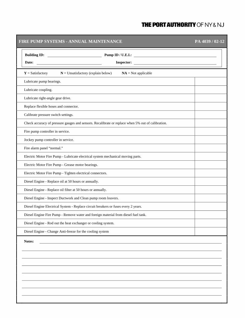
FIRE PUMP SYSTEMS - ANNUAL MAINTENANCE PA 4039 / 02-12
Building ID: Pump ID / U.E.I.:
Date: Inspector:
Y = Satisfactory N = Unsatisfactory (explain below) NA = Not applicable
Lubricate pump bearings.
Lubricate coupling.
Lubricate right-angle gear drive.
Replace flexible hoses and connector.
Calibrate pressure switch settings.
Check accuracy of pressure gauges and sensors. Recalibrate or replace when 5% out of calibration.
Fire pump controller in service.
Jockey pump controller in service.
Fire alarm panel “normal.”
Electric Motor Fire Pump - Lubricate electrical system mechanical moving parts.
Electric Motor Fire Pump - Grease motor bearings.
Electric Motor Fire Pump - Tighten electrical connectors.
Diesel Engine - Replace oil at 50 hours or annually.
Diesel Engine - Replace oil filter at 50 hours or annually.
Diesel Engine - Inspect Ductwork and Clean pump room louvers.
Diesel Engine Electrical System - Replace circuit breakers or fuses every 2 years.
Diesel Engine Fire Pump - Remove water and foreign material from diesel fuel tank.
Diesel Engine - Rod out the heat exchanger or cooling system.
Diesel Engine - Change Anti-freeze for the cooling system
Notes:
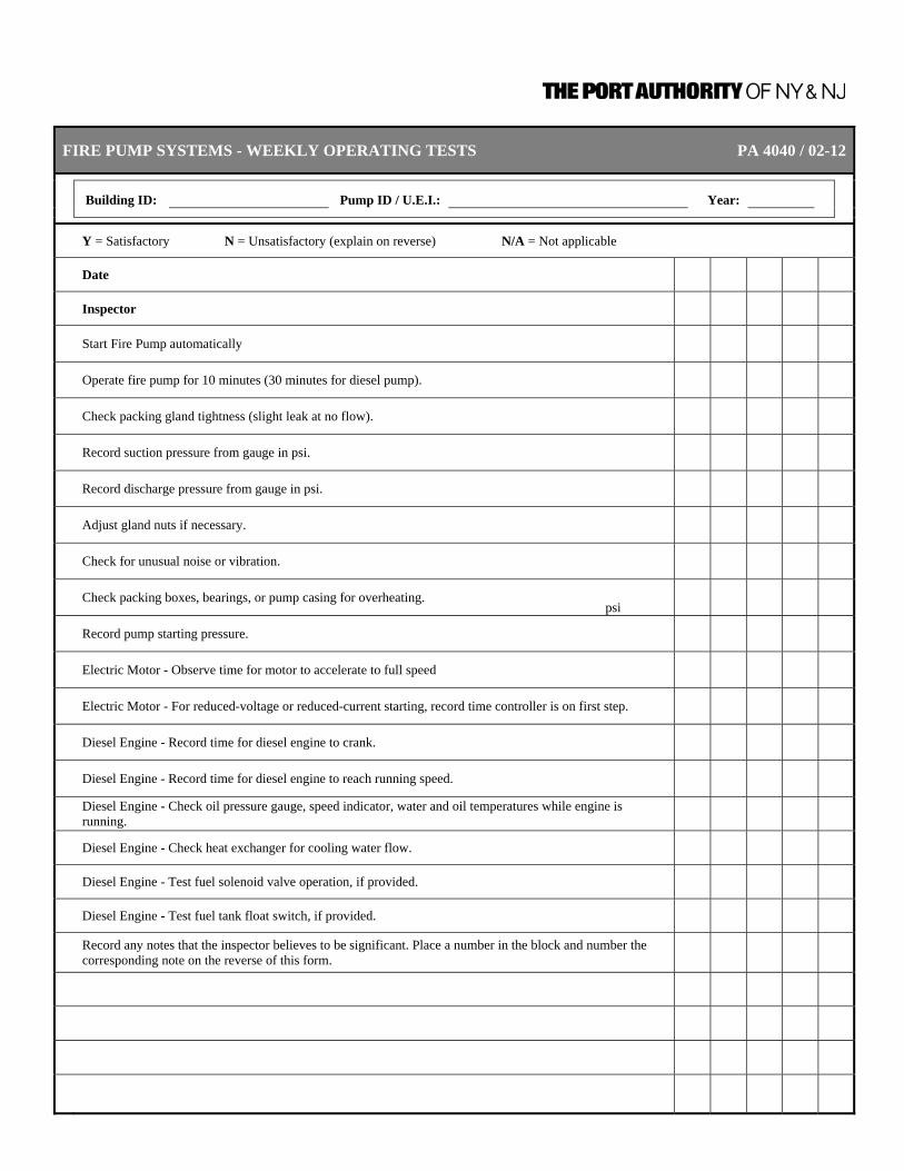
FIRE PUMP SYSTEMS - WEEKLY OPERATING TESTS PA 4040 / 02-12
Building ID: Pump ID / U.E.I.: Year:
Y = Satisfactory N = Unsatisfactory (explain on reverse) N/A = Not applicable
Date
Inspector
Start Fire Pump automatically
Operate fire pump for 10 minutes (30 minutes for diesel pump).
Check packing gland tightness (slight leak at no flow).
Record suction pressure from gauge in psi.
Record discharge pressure from gauge in psi.
Adjust gland nuts if necessary.
Check for unusual noise or vibration.
Check packing boxes, bearings, or pump casing for overheating. psi
Record pump starting pressure.
Electric Motor - Observe time for motor to accelerate to full speed
Electric Motor - For reduced-voltage or reduced-current starting, record time controller is on first step.
Diesel Engine - Record time for diesel engine to crank.
Diesel Engine - Record time for diesel engine to reach running speed.
Diesel Engine - Check oil pressure gauge, speed indicator, water and oil temperatures while engine is running.
Diesel Engine - Check heat exchanger for cooling water flow.
Diesel Engine - Test fuel solenoid valve operation, if provided.
Diesel Engine - Test fuel tank float switch, if provided.
Record any notes that the inspector believes to be significant. Place a number in the block and number the corresponding note on the reverse of this form.

FIRE PUMP SYSTEMS - MONTHLY AND SEMI-ANNUAL TESTS PA 4041 / 02-12
Building ID: Pump ID / U.E.I.: Year:
Y = Satisfactory N = Unsatisfactory (explain below) N/A = Not applicable
Monthly
Date
Inspector
Exercise isolating switch and circuit breaker.
Test batteries for specific gravity or state of charge.
Semi-Annually
Date
Inspector
Test antifreeze to determine protection level.
Operate manual starting means.
Operate safety devices and alarms.
Notes:

FIRE PUMP SYSTEMS - ANNUAL PERFORMANCE TESTS PA 4042 / 02-12
Building ID: Pump ID / U.E.I.:
Date: Inspector:
Y = Satisfactory N = Unsatisfactory (explain below) NA = Not Applicable
Inspect and Operate Emergency Manual Start Electric Motor - Check operation of circulation relief
valve
Automatic start functions properly. Check operation of Main Pressure Relief Valve
Automatic stop functions properly. Timer reset and graph paper changed?
Automatic start:
psi Timer indicates total run time:
Min
Manual start functions properly.
Electric Motor Pumps - Simulate power failure while pump is operating at peak load.
Manual stop functions properly. Electric Motor Pumps - Verify that Transfer Switch
transfers power to alternate power source.
Remote start functions properly.
Electric Motor Pumps - Verify performance of pump at peak load on emergency power source.
Jockey pump operational. Electric Motor Pumps - Remove power failure condition
and verify pump reconnects to normal power source.
Jockey pump “turn-on” pressure:
psi Jockey pump appears properly aligned.
Jockey pump “turn-off” pressure:
psi Jockey pump valves open.
Test data and flow charts completed. (Attach all water-flow charts, electrical power charts, performance curves, etc.)
Notes:
Continue on reverse if necessary.

FIRE PUMP SYSTEMS - ANNUAL TEST SUMMARY PAGE PA 4043 / 02-12
Building ID: Pump ID / U.E.I.:
Date: Inspector:
Test 1 Test 2 Test 3
Approximate percent of rated pump discharge (gpm)/(L/min) 0 100% 150%
Nozzle size in inches (mm) No flow
Pitot pressure in psi (bar) None
Flow in gpm (L/min) None
Pump suction in psi (bar)
Pump discharge in psi (bar)
Net pump head (discharge pressure minus suction pressure)
Pump speed (rpm)
Electric Motor - Record electrical voltage
Electric Motor - Record current (all lines)
Electric Motor - Operate electric circuit breaker.
Diesel Engine - Check for excessive back pressure in exhaust system.
Notes:

Inspection, Testing, and Maintenance Requirements for Fire Protection and Life Safety Systems
CHAPTER 5 – WATER STORAGE TANKS 9/30/2011 | Page 5-1
CHAPTER 5 – WATER STORAGE TANKS
A. ALL WATER STORAGE TANKS 1. Existing Water Storage Tanks
General Information Update Annually Form PA 4045
Review General Information Form for all Water Storage Tanks, update as required.
2. New or Altered Water Storage
Tanks – General Information Update As Required Form PA 4045
Complete General Information Form for new Water Storage Tanks or update General Information Form for Water Storage Tanks that have been altered to include repairs and/or modifications to components.
3. Water Level Inspection Monthly Form PA 4046
9.2.1.2 Tanks not equipped with supervised water level alarms that are connected to a constantly attended location shall be inspected monthly.
4. Water Level Inspection Quarterly Form PA 4046
9.2.1.1 Tanks equipped with supervised water level alarms that are connected to a constantly attended location shall be inspected quarterly.
5. Water Level Testing 5 Years Form PA 4048
9.3.1 Level indicators shall be tested every 5 years for accuracy and freedom of movement.

Inspection, Testing, and Maintenance Requirements for Fire Protection and Life Safety Systems
CHAPTER 5 – WATER STORAGE TANKS 9/30/2011 | Page 5-2
6. Water Level Maintenance As Needed Form PA 4046
9.4.1 The tank shall be maintained full or at the designed water level.
The water level should never be lower than 76 mm to 102 mm (3 in. to 4 in.) below the designated fire service level.
7. Water Level Alarms Testing Semi-Annually Form PA 4050
9.3.5 High and low water level alarms shall be tested semiannually.
8. Water Temperature Inspection Daily Form PA 4047
9.2.4.1 The temperature of water tanks shall not be less than 4°C (40°F). 9.2.4.3 The temperature of water in tanks without low temperature alarms connected
to a constantly attended location shall be inspected and recorded daily during the heating season.
9. Water Temperature Inspection Weekly Form PA 4046
9.2.4.2 The temperature of water in tanks with low temperature alarms connected to a constantly attended location shall be inspected and recorded weekly during the heating season.
10. Heating System Inspection Daily Form PA 4047
9.2.3.2 Tank heating systems without a supervised low temperature alarm connected to a constantly attended location shall be inspected daily during the heating season.
11. Heating System Inspection Weekly Form PA 4046
9.2.3.1 Tank heating systems installed on tanks equipped with a supervised low water temperature alarm that are connected to a constantly attended location shall be inspected weekly.

Inspection, Testing, and Maintenance Requirements for Fire Protection and Life Safety Systems
CHAPTER 5 – WATER STORAGE TANKS 9/30/2011 | Page 5-3
12. High Water Temperature Limit
Switches Testing Monthly Form PA 4049
9.3.4 High water temperature limit switches on tank heating systems, where
provided, shall be tested monthly whenever the heating system is in service. 13. Pressure Gauges Testing 5 Years Form PA 4048
9.3.6 Pressure gauges shall be tested every 5 years with a calibrated gauge in accordance with the manufacturer’s instructions. Gauges not accurate to within 3 percent of the scale of the gauge being tested shall be recalibrated or replaced.
14. Control Valves – Sealed Inspection Weekly Form PA 4046
12.3.2.1 All valves shall be inspected weekly.
12.3.2.2 The valve inspection shall verify that the valves are in the following condition: 1) In the normal open or closed position 2) Properly sealed, locked, or supervised 3) Accessible 4) Provided with appropriate wrenches 5) Free from external leaks 6) Provided with appropriate identification
15. Control Valves –
Locked/Supervised Inspection Monthly Form PA 4046
12.3.2.1.1 Valves secured with locks or supervised in accordance with applicable NFPA
standards shall be permitted to be inspected monthly.
12.3.2.2 The valve inspection shall verify that the valves are in the following condition: 1) In the normal open or closed position 2) Properly sealed, locked, or supervised 3) Accessible 4) Provided with appropriate wrenches 5) Free from external leaks 6) Provided with appropriate identification

Inspection, Testing, and Maintenance Requirements for Fire Protection and Life Safety Systems
CHAPTER 5 – WATER STORAGE TANKS 9/30/2011 | Page 5-4
16. Control Valves Testing Annually Form PA 4005
12.3.3.1 Each control valve shall be operated annually through its full range and returned to its normal position. The testing required by 12.3.3.1 should include counting the number of turns needed to fully close and open the valve. Also, the valve stem should be lubricated before opening and closing.
12.3.3.2 Post indicator valves shall be opened until spring or torsion is felt in the rod,
indicating that the rod has not become detached from the valve. 17. Control Valves Testing Semi-Annually Form PA 4004
12.3.3.5.1 Valve supervisory switches shall be tested semiannually.
12.3.3.5.2 A distinctive signal shall indicate movement from the valve’s normal position during either the first two revolutions of a hand wheel or when the stem of the valve has moved one-fifth of the distance from its normal position.
12.3.3.5.3 The signal shall not be restored at any valve position except the normal
position. 18. Control Valves Maintenance Annually Form PA 4005
12.3.4.1 The operating stems of outside screw and yoke valves shall be lubricated annually.
12.3.4.2 The valve then shall be completely closed and reopened to test its operation
and distribute the lubricant. 19. Tank – Exterior Inspection Quarterly Form PA 4046
9.2.5.1 The exterior of the tank, supporting structure, vents, foundation, and catwalks or ladders, where provided, shall be inspected quarterly for signs of obvious damage or weakening.

Inspection, Testing, and Maintenance Requirements for Fire Protection and Life Safety Systems
CHAPTER 5 – WATER STORAGE TANKS 9/30/2011 | Page 5-5
20. Tank – Exterior Inspection Quarterly Form PA 4046
9.2.5.2 The area surrounding the tank and supporting structure, where provided, shall be inspected quarterly to ensure that the following conditions are met: 1) The area is free of combustible storage, trash, debris, brush, or
material that could present a fire exposure hazard. 2) The area is free of the accumulation of material on or near parts
that could result in accelerated corrosion or rot. 3) The tank and support are free of ice buildup. 4) The exterior sides and top of embankments supporting coated
fabric tanks are free of erosion. 21. Tank – Exterior Inspection Annually Form PA 4046
9.2.5.3 Expansion joints, where provided, shall be inspected annually for leaks and cracks.
9.2.5.4 The hoops and grillage of wooden tanks shall be inspected annually
9.2.5.5 Exterior paint coated, or insulated surfaces of the tank and supporting
structure, where provided, shall be inspected annually for signs of degradation.
22. Tank – Interior Inspection 3 Years Form PA 4048
9.2.6 When an interior inspection of a tank is performed, it is critical to comply with proper safety precautions, including confined space entry requirements.
9.2.6.1.1 The interior of steel tanks without corrosion protection shall be inspected
every 3 years. 23. Tank – Interior Inspection 5 Years Form PA 4048
9.2.6.1.2 The interior of all other types of tanks shall be inspected every 5 years.
9.2.6.2 Where interior inspection is made my means of underwater evaluation, silt shall first be removed from the tank floor.
9.2.6.3 The tank interior shall be inspected for signs of pitting, corrosion, spalling,
rot, other forms of deterioration, waste materials and debris, aquatic growth, and local or general failure of interior coating.
9.2.6.4 Steel tanks exhibiting signs of interior pitting, corrosion, or failure of coating
shall be tested in accordance with 9.2.7.

Inspection, Testing, and Maintenance Requirements for Fire Protection and Life Safety Systems
CHAPTER 5 – WATER STORAGE TANKS 9/30/2011 | Page 5-6
9.2.6.5 Tanks on ring-type foundations with sand in the middle shall be inspected for
evidence of voids beneath the floor.
9.2.6.7 The anti-vortex plate shall be inspected for deterioration or blockage.
9.2.7 Interior Inspection. Where a drained interior inspection of a steel tank is conducted in accordance with 9.2.6.4, the following tests shall be conducted:
1) Evaluation of tank coatings shall be made in accordance with the
adhesion test of ASTM D 3359, Standard Test Methods for Measuring Adhesion by Tape Test, generally referred to as the “cross-hatch test.”
2) Dry film thickness measurements shall be taken at random
locations to determine the overall coating thickness.
3) Nondestructive ultrasonic readings shall be taken to evaluate the wall thickness where there is evidence of pitting or corrosion.
4) Interior surfaces shall be spot wet-sponge tested to detect pinholes,
cracks, or other compromises in the coating. Special attention shall be given to sharp edges such as ladder rungs, nuts, and bolts.
5) Tank bottoms shall be tested for metal loss and/or rust on the
underside by use of ultrasonic testing where there is evidence of pitting or corrosion. Removal, visual inspection, and replacement of random floor coupons shall be an acceptable alternative to ultrasonic testing.
6) Tanks with flat bottoms shall be vacuum-box tested at bottom
seams in accordance with test procedures found in NFPA 22, Standard for Water Tanks for Private Fire Protection.
24. Drain Silt Maintenance As Required Form PA 4048
9.4.5 Silt shall be removed during interior inspections or more frequently as needed to avoid accumulation to the level of the tank outlet.

Inspection, Testing, and Maintenance Requirements for Fire Protection and Life Safety Systems
CHAPTER 5 – WATER STORAGE TANKS 9/30/2011 | Page 5-7
B. PRESSURE TANKS In addition to A above, the following is required for Pressure Tanks. 1. Air Pressure Inspection Monthly Form PA 4046
9.2.2.2 The air pressure in pressure tanks with a non-supervised air pressure source shall be inspected monthly.
2. Air Pressure Inspection Quarterly Form PA 4046
9.2.2.1 Pressure tanks that have their air pressure source supervised shall be inspected quarterly.

WATER STORAGE TANKS - GENERAL INFORMATION PA 4045 / 02-12
Original Installation Date: U.E.I. (Unique Element Identification) :
Dates Reviewed:
Storage Tank ID:
Location:
Tank Provides Supply to:
Storage Tank Information Tank Capacity Tank Construction Tank Protection Heating System Description (if provided) Automatic Refill Yes No Define automatic refill operation
Storage Tank Alarms High Level Alarm Low Level Alarm Water Temperature Alarms Transmit To:
Pressure Tanks Tank Capacity Volume of water Air Pressure Air Compressor Rating Air Pressure supervised
Control Valves
Number of Control Valves
How are valves supervised? Seated Locked Tamper switch
Are valves indentified with signs? Yes No
Notes:

WATER STORAGE TANKS - WEEKLY, MONTHLY AND QUARTERLY INSPECTIONS PA 4046 / 02-12
Building ID: System ID / U.E.I.:
Y = Satisfactory N = Unsatisfactory (explain below)
Weekly
Date
Inspector
Control valves are properly arranged.
Inspect and record water temperature in tanks with low temperature alarms.
Inspect heating system.
Monthly
Date
Inspector
Check air pressure in pressure tanks with a non-supervised air pressure source.
Water level is at normal height.
Verify that control valves are secured.
Quarterly
Date
Inspector
Tank exterior condition is satisfactory.
Tank support structure is satisfactory.
Tank catwalks and ladders are satisfactory.
Area around tank is free of debris; there are no signs of leakage.
Check air pressure in pressure tanks with a supervised air pressure source.
Water level is at normal height.
Area surrounding the tank and supporting structure.
Notes:

WATER STORAGE TANKS - DAILY INSPECTIONS PA 4047 / 02-12
Building ID: System ID / U.E.I.:
1. Tank heating systems without a supervised low temperature alarm connected to a constantly attended location shall be inspected daily during the heating season.
2. The temperature of water in tanks without low temperature alarms connected to a constantly attended location shall be inspected and recorded daily during the heating season.
Y = Satisfactory N = Unsatisfactory (explain below)
Date Inspector Heating System (1)
Water Temperature (2) Notes

WATER STORAGE TANKS - 3 AND 5 YEAR INSPECTIONS & TESTS PA 4048 / 02-12
Building ID: System ID / U.E.I.:
Y = Satisfactory N = Unsatisfactory (explain below)
3-Year Inspection
Date
Inspector
Inspect the tank interior of steel tanks without corrosion protection.
Remove silt to avoid accumulation to the level of the tank outlet.
5-Year Inspection
Date
Inspector
Tank interior shows no signs of rust, corrosion, or collection of debris.
Remove silt to avoid accumulation to the level of the tank outlet.
Test water storage tank level indicators for accuracy.
Pressure gauges calibration.
Notes:

WATER STORAGE TANKS - MONTHLY TESTS DURING PA 4049 / 02-12 COLD WEATHER / HEATING SEASON
Building ID: System ID / U.E.I.:
Y = Satisfactory N = Unsatisfactory (explain below) N/A = Not applicable
Date Inspector
High-temperature limit switches operate properly.
Notes:

WATER STORAGE TANKS - SEMI-ANNUAL/ANNUAL TESTS AND MAINTENANCE PA 4050 / 02-12
Building ID: System ID / U.E.I.:
Y = Satisfactory N = Unsatisfactory (explain below)
Date
Inspector
Test high and low water-level alarms operate properly.
Inspect expansion joints for leaks and cracks.
Inspect hoops and grillage of wooden tanks.
Inspect exterior painted, coated, or insulated surfaces of tanks and supporting structure for signs of degradation.
Notes:
Inspection, Testing, and Maintenance Requirements for Fire Protection and Life Safety Systems
CHAPTER 6 – FOAM FIRE SUPPRESSION SYSTEMS 9/30/2011 | Page 6-1
CHAPTER 6 – FOAM FIRE SUPPRESSION SYSTEMS
DEFINITIONS
Control Valve A valve controlling flow to water-based fire protection systems. Control valves do not include hose valves, inspector’s test valves, drain valves, trim valves for dry pipe, preaction and deluge valves, check valves, or relief valves.
Discharge Device. A device designed to discharge water or foam-water solution
in a predetermined, fixed, or adjustable pattern. Examples include, but are not limited to, sprinklers, spray nozzles, and hose nozzles.
Foam Concentrate. A liquid that is stored in a containment vessel and is metered
into a flowing water stream at a specified concentration by the proportioning system.
Foam Discharge Device. Any device that, when fed with a foam-water solution,
produces foam. These devices shall be permitted to be non-air-aspirating (e.g., sprinklers, water nozzles) or air-aspirating (e.g., foam-water sprinklers, directional foam-water nozzles, foam nozzles). All discharge devices have a special pattern of distribution peculiar to the particular device.
Orifice Plate Proportioning. This system utilizes an orifice plate(s) through which passes
a specific amount of foam concentrate at a specific pressure drop across the orifice plate(s).
Bladder Tank Proportioner. This system is similar to a standard pressure proportioner,
except the foam concentrate is contained inside a diaphragm bag that is contained inside a pressure vessel. Operation is the same as a standard pressure proportioner, except that, because of the separation of the foam concentrate and water, this system can be used with all foam concentrates, regardless of specific gravity.
In-Line Balanced Pressure This system is similar to a standard balanced pressure Proportioner. system, except the pumped concentrate pressure is
maintained at a fixed preset value. Balancing of water and liquid takes place at individual proportioners located in the system riser or in segments of multiple systems.
Line Proportioner. This system uses a venture pickup-type device where water
passing through the unit creates a vacuum, thereby allowing foam concentrate to be picked up from an atmospheric storage container.
Inspection, Testing, and Maintenance Requirements for Fire Protection and Life Safety Systems
CHAPTER 6 – FOAM FIRE SUPPRESSION SYSTEMS 9/30/2011 | Page 6-2
Foam. Fire-fighting foam, within the scope of this standard, is a
stable aggregation of small bubbles of lower density than oil or water that exhibits a tenacity for covering horizontal surfaces. Air foam is made by mixing air into a water solution, containing a foam concentrate, by means of suitably designed equipment. It flows freely over a burning liquid surface and forms a tough, air-excluding, continuous blanket that seals volatile combustible vapors from access to air. It resists disruption from wind and draft or heat and flame attack and is capable of resealing in case of mechanical rupture. Fire-fighting foams retain these properties for relatively long periods of time. Foams also are defined by expansion and are arbitrarily subdivided into three ranges of expansion. These ranges correspond broadly to certain types of usage described below. The three ranges are as follows: (1) Low-expansion foam — expansion up to 20; (2) Medium-expansion foam—expansion from 20 to 200; (3) High-expansion foam—expansion from 200 to 1000.
Standard Balanced Pressure This system utilizes a foam concentrate pump. Foam Proportioner. concentrate is drawn from an atmospheric storage tank, is
pressurized by the pump, and passes back through a diaphragm balancing valve to the storage tank. Water- and foam concentrate-sensing lines are directed to the balancing valve and maintain the foam liquid at a pressure equal to that of the water pressure. The two equal pressures are fed to the proportioner proper and are mixed at a predetermined rate.
Standard Pressure Proportioner. This system uses a pressure vessel containing foam
concentrate. Water is supplied to the proportioner, which directs an amount of the supply downward onto the contained concentrate, thereby pressurizing the tank. Pressurized concentrate then is forced through an orifice back into the flowing water stream. This type of system is applicable for use with foam concentrates having a specific gravity substantially higher than water. It is not applicable for use with foam concentrates with a specific gravity at or near that of water.
Foam-Water Spray System. A special system that is pipe connected to a source of foam
concentrate and to a water supply. The system is equipped with foam-water spray nozzles for extinguishing agent discharge (foam followed by water or in reverse order) and for distribution over the area to be protected. System operation arrangements parallel those for foam-water sprinkler systems as described in the definition of Foam-Water Sprinkler System. [16:1.3]
Foam-Water Sprinkler System. A special system pipe connected to a source of foam
concentrate and to a water supply and equipped with appropriate discharge devices for fire protection agent discharge and for distribution over the area to be protected.
Inspection, Testing, and Maintenance Requirements for Fire Protection and Life Safety Systems
CHAPTER 6 – FOAM FIRE SUPPRESSION SYSTEMS 9/30/2011 | Page 6-3
The piping system is connected to the water supply through a control valve that usually is actuated by operation of automatic detection equipment installed in the same areas as the sprinklers. When this valve opens, water flows into the piping system and foam concentrate is injected into the water. The resulting foam solution discharging through the discharge devices generates and distributes foam. Upon exhaustion of the foam concentrate supply, water discharge follows and continues until shut off manually. Systems also can be used for discharge of water first, followed by discharge of foam for a specific period, and then followed by water until manually shut off. Existing deluge sprinkler systems that have been converted to the use of aqueous film forming foam are classed as foam-water sprinkler systems.
Alcohol-Resistant Foam Concentrate. This concentrate is used for fighting fires on water-soluble
materials and other fuels destructive to regular, AFFF, or FFFP foams, as well as for fires involving hydrocarbons. There are three general types. One is based on water-soluble natural polymers, such as protein or fluoroprotein concentrates, and also contains alcohol-insoluble materials that precipitate as an insoluble barrier in the bubble structure. The second type is based on synthetic concentrates and contains a gelling agent that surrounds the foam bubbles and forms a protective raft on the surface of water-soluble fuels; these foams can also have film forming characteristics on hydrocarbon fuels. The third type is based on both water-soluble natural polymers, such as fluoroprotein, and contains a gelling agent that protects the foam from water-soluble fuels. This foam can also have film forming and fluoroprotein characteristics on hydrocarbon fuels. Alcohol-resistant foam concentrates are generally used in concentrations of 3 percent to 10 percent solutions, depending on the nature of the hazard to be protected and the type of concentrate.
Aqueous Film-Forming Foam (AFFF) This concentrate is based on fluorinated surfactants plus Concentrate. foam stabilizers and usually diluted with water to a 1 percent,
3 percent, or 6 percent solution. The foam formed acts as a barrier both to exclude air or oxygen and to develop an aqueous film on the fuel surface capable of suppressing the evolution of fuel vapors. The foam produced with AFFF concentrate is dry chemical compatible and thus is suitable for combined use with dry chemicals.
Film-Forming Fluoroprotein (FFFP) This concentrate uses fluorinated surfactants to produce a Foam Concentrate. fluid aqueous film for suppressing hydrocarbon fuel vapors.
This type of foam utilizes a protein base plus stabilizing additives and inhibitors to protect against freezing, corrosion, and bacterial decomposition, and it also resists fuel pickup. The foam is usually diluted with water to a 3 percent or 6 percent solution and is dry chemical compatible.

Inspection, Testing, and Maintenance Requirements for Fire Protection and Life Safety Systems
CHAPTER 6 – FOAM FIRE SUPPRESSION SYSTEMS 9/30/2011 | Page 6-4
Fluoroprotein Foam Concentrate. Fluoroprotein foam concentrate is very similar to protein-foam concentrate but has a synthetic fluorinated surfactant additive. In addition to an air-excluding foam blanket, they also can deposit a vaporization-preventing film on the surface of a liquid fuel. It is diluted with water to form 3 percent to 6 percent solutions depending on the type. This concentrate is compatible with certain dry chemicals. [11:3.3]
Medium- and High-Expansion This concentrate, which is usually derived from hydrocarbon Foam Concentrate. surfactants, is used in specially designed equipment to
produce foams having foam-to-solution volume ratios of 20:1 to approximately 1000:1. This equipment can be air aspirating or blower-fan type. [11:3.3]
Other Synthetic Foam Concentrate. Other synthetic foam concentrate is based on hydrocarbon
surface active agents and is listed as a wetting agent, foaming agent, or both. In general, its use is limited to portable nozzle foam application for spill fires within the scope of their listings. The appropriate listings shall be consulted to determine proper application rates and methods. [11:3.3]
Protein Foam Concentrate. Protein-foam concentrate consists primarily of products from
a protein hydrolysate, plus stabilizing additives and inhibitors to protect against freezing, to prevent corrosion of equipment and containers, to resist bacterial decomposition, to control viscosity, and to otherwise ensure readiness for use under emergency conditions. They are diluted with water to form 3 percent to 6 percent solutions depending on the type. These concentrates are compatible with certain dry chemicals.
Synthetic Foam Concentrate. Synthetic foam concentrate is based on foaming agents
other than hydrolyzed proteins and include aqueous film-forming foam (AFFF) concentrates, medium- and high-expansion foam concentrates, and other synthetic foam concentrates.
Foam Solution. A homogeneous mixture of water and foam concentrate in
the proper proportions. For the purpose of this document, “foam solution” and “solution” are used interchangeably. [11:3.3]
Foam-Water Sprinkler System. A special system that is pipe-connected to a source of foam
concentrate and to a water supply. The system is equipped with appropriate discharge devices for extinguishing agent discharge and for distribution over the area to be protected. The piping system is connected to the water supply through a control valve that usually is actuated by operation of automatic detection equipment that is installed in the same areas as the sprinklers. When this valve opens, water flows into the piping system, foam concentrate is injected into the water, and the resulting foam solution discharging through the discharge devices generates and distributes foam. Upon exhaustion of the foam concentrate supply, water discharge follows and continues until shut off manually.

Inspection, Testing, and Maintenance Requirements for Fire Protection and Life Safety Systems
CHAPTER 6 – FOAM FIRE SUPPRESSION SYSTEMS 9/30/2011 | Page 6-5
Systems can be used for discharge of water first, followed by discharge of foam for a specified period, and then followed by water until manually shut off. Existing deluge sprinkler systems that have been converted to the use of aqueous film-forming foam or film-forming fluoroprotein foam are classified as foam-water sprinkler systems.
Foam-Water Deluge System A foam-water sprinkler system employing open discharge
devices, which are attached to a piping system that is connected to a water supply through a valve that is opened by the operation of a detection system, which is installed in the same areas as the discharge devices. When this valve opens, water flows into the piping system and discharges from all discharge devices attached thereto.
Foam-Water Dry Pipe System A sprinkler system employing automatic sprinklers or
nozzles that are attached to a piping system that contains air or nitrogen under pressure, the release of which (as from the opening of a sprinkler) permits the water pressure to open a valve known as a dry pipe valve. The water then flows into the piping system and out the opened sprinklers.
Foam-Water Preaction System. A sprinkler system employing automatic sprinklers or
nozzles attached to a piping system containing air that might or might not be under pressure, with a supplemental detection system installed in the same area as the sprinklers. Actuation of the detection system opens a valve that permits water to flow into the sprinkler piping system and to be discharged from any sprinklers that have activated.
Foam-Water Spray System. A special system that is pipe-connected to a source of foam
concentrate and to a water supply. The system is equipped with foam–water spray nozzles for extinguishing agent discharge (foam followed by water or in reverse order) and for distribution over the area to be protected. System operation arrangements parallel those for foam-water sprinkler systems as described in the definition of Foam-Water Sprinkler System.
Preprimed System. A wet pipe system containing foam solution. Proportioning. Proportioning is the continuous introduction of foam
concentrate at the recommended ratio into the water stream to form foam solution.

Inspection, Testing, and Maintenance Requirements for Fire Protection and Life Safety Systems
CHAPTER 6 – FOAM FIRE SUPPRESSION SYSTEMS 9/30/2011 | Page 6-6
A. All Foam Fire Suppression Systems 1. Existing Foam Water Systems
General Information Update Annually Form PA 4054
Review General Information Form for all Foam Fire Suppression Systems, update as required.
Confirm that operating and maintenance instructions, maintenance manuals, and a full set of drawings are provided as required. Additionally, confirm that staff working on the foam fire suppression systems are trained and knowledgeable.
11.7.1 Operating and maintenance instructions and layouts shall be posted at
control equipment with a second copy on file.
11.7.2 All persons who are expected to inspect, test, maintain, or operate foam-generating apparatus shall be thoroughly trained and training shall be kept current over time.
2. New or Altered Foam Water
Systems – General Information Update As Required Form PA 4054
Complete General Information Form for new Foam Fire Suppression Systems or update General Information Form for Foam Fire Suppression Systems that have been altered to include repairs and/or modifications to components. Confirm that operating and maintenance instructions, maintenance manuals, and a full set of drawings are provided as required. Additionally, confirm that staff working on the foam fire suppression systems are trained and knowledgeable.
11.7.1 Operating and maintenance instructions and layouts shall be posted at
control equipment with a second copy on file.
11.7.2 All persons who are expected to inspect, test, maintain, or operate foam-generating apparatus shall be thoroughly trained and training shall be kept current over time.

Inspection, Testing, and Maintenance Requirements for Fire Protection and Life Safety Systems
CHAPTER 6 – FOAM FIRE SUPPRESSION SYSTEMS 9/30/2011 | Page 6-7
B. Foam-Water Sprinkler and Foam-Water Spray
Systems
This section provides the requirements for inspection, testing, and maintenance for Foam-Water systems as specified in NFPA 16, Standard for the Installation of Foam-Water Sprinkler and Foam-Water Spray Systems. This section does not include all of the requirements for Foam Fire Suppression Systems for Aircraft Hangars or other Low-, Medium-, and High- Expansion Foam Fire Suppression Systems identified in Sections B and C below. Examples of Foam Water systems covered by this section are systems designed to protect transformers, building property, and storage tanks that utilize sprinkler or spray nozzle heads. Foam-Water Sprinkler and Foam-Water Spray Systems in Aircraft Hangars must comply with the requirements of this section and Section C of this Chapter.
1. Discharge Device (Sprinkler)
Location and Position Inspection Annually Form PA 4058
2. Discharge Device (Spray
Nozzle) Location and Position Inspection Monthly Form PA 4056
11.2.5 Discharge devices for foam-water spray systems can be either aspirating or
non-aspirating. Discharge devices for foam-water sprinkler systems, such as wet, dry, or pre-action systems are automatic in operation and must be non-air aspirating.
11.2.5.1 Foam-water discharge devices shall be inspected visually and maintained to
ensure that they are in place, continue to be aimed or pointed in the direction intended in the system design, and are free from external loading and corrosion.
11.2.5.2 Where caps or plugs are required, the inspection shall confirm they are in
place and free to operate as intended.
11.2.5.3 Misaligned discharge devices shall be adjusted (aimed) by visual means, and the discharge patterns shall be checked at the next scheduled flow test.
11.2.5.4 Discharge devices are listed or approved for particular foam concentrates.
Inspection shall verify that unlisted combinations of discharge devices and foam concentrate have not been substituted.

Inspection, Testing, and Maintenance Requirements for Fire Protection and Life Safety Systems
CHAPTER 6 – FOAM FIRE SUPPRESSION SYSTEMS 9/30/2011 | Page 6-8
3. Discharge Device Location
Location, Position, Obstruction
Testing Annually Form PA 4060
11.3.3.6.1 The discharge patterns from all of the open spray devices shall be observed
to ensure that patterns are not impeded by plugged discharge devices and to ensure that discharge devices are correctly positioned and that obstructions do not prevent discharge patterns from covering surfaces to be protected.
11.3.3.6.2 Where obstructions occur, the piping and discharge devices shall be cleaned
and the system retested.
11.3.3.6.3 Discharge devices shall be permitted to be of different orifice sizes and types.
4. Foam Concentrate Strainer(s) Inspection Quarterly Form PA 4057
11.2.7.2 Foam concentrate strainers shall be inspected visually to ensure the blow-down valve is closed and plugged.
5. Foam Concentrate Strainer(s) Testing Annually Form PA 4060
11.2.7.2.1 Baskets or screens shall be removed and inspected after each operation or flow test.
6. Strainer(s) – Mainline Testing Annually Form PA 4060
11.2.7.1 Mainline and individual discharge device strainers (basket or screen) shall be inspected in accordance with the provisions of Chapter 10 of NFPA 25®, 2002.
10.2.7.1 Mainline strainers (basket or screen) shall be flushed until clear after each
operation or flow test.
10.2.7.2 Individual water spray nozzle strainers shall be removed, cleaned, and inspected after each operation or flow test.
10.2.7.3 All strainers shall be inspected and cleaned in accordance with the
manufacturer’s instructions.
10.2.7.44 Damaged or corroded parts shall be replaced or repaired.
Inspection, Testing, and Maintenance Requirements for Fire Protection and Life Safety Systems
CHAPTER 6 – FOAM FIRE SUPPRESSION SYSTEMS 9/30/2011 | Page 6-9
7. Drainage in System Area Inspection Quarterly Form PA 4057
11.2.8 Drainage. The area beneath and surrounding a foam-water spray system shall be inspected to ensure that drainage facilities, such as trap sumps and drainage trenches, are not blocked and retention embankments or dikes are in good repair.
8. Proportioning System(s) – All Inspection Monthly Form PA 4056
11.2.9.2 Valves specified to be checked shall be permitted to be open or closed, depending upon specific functions within each foam-water system.
11.2.9.3 The position (open or closed) of valves shall be verified in accordance with
specific operating conditions.
11.2.9.4 Inspection of the concentrate tank shall include verification that the quantity of foam concentrate satisfies the requirements of the original design.
11.2.9.5 Additional inspection requirements shall be performed as detailed for the
proportioning systems specified in 11.2.9.
11.2.9.5.1 Standard Pressure Proportioner. This is a pressure vessel. The pressure shall be removed before the inspection to prevent injury. The inspection shall verify the following:
1) Ball drip valves (automatic drains) are free and opened 2) External corrosion on foam concentrate storage tanks is not present
11.2.9.5.2 Bladder Tank Proportioner. This is a pressure vessel. The pressure shall
be removed before the inspection of present injury. The inspection shall include the following: 1) Water control valves to foam concentrate tank 2) A check for external corrosion on foam concentrate storage tanks 3) A check for the presence of foam in the water surrounding the
bladder (annual)
11.2.9.5.3 Line Proportioner. The inspection shall include the following: 1) Strainers 2) Verification that pressure vacuum vent is operating freely 3) A check for external corrosion on foam concentrate storage tanks
11.2.9.5.4 Standard Balanced Pressure Proportioner. The inspection shall include
the following: 1) Strainers 2) Verification that pressure vacuum vent is operating freely 3) Verification that gauges are in good operating condition 4) Verification that sensing line valves are open 5) Verification that power is available to foam liquid pump

Inspection, Testing, and Maintenance Requirements for Fire Protection and Life Safety Systems
CHAPTER 6 – FOAM FIRE SUPPRESSION SYSTEMS 9/30/2011 | Page 6-10
11.2.9.5.5 In-Line Balanced Pressure Proportioner. The inspection shall include the
following: 1) Strainers 2) Verification that pressure vacuum vent is operating freely 3) Verification that gauges are in good working condition 4) Verification that sensing line valves at pump unit and individual
proportioner stations are open 5) Verification that power is available to foam liquid pump
11.2.9.5.6 Orifice Plate Proportioner. The inspection shall include the following:
1) Strainers 2) Verification that pressure vacuum vent is operating freely 3) Verification that gauges are in good working condition 4) Verification that power is available to foam liquid pump
9. Pipe and Fittings
(Corrosion and Damage) Inspection Quarterly Form PA 4057
11.2.3 System piping and fittings shall be inspected for the following:
1) Mechanical Damage (e.g., broken piping or cracked fittings) 2) External conditions (e.g., missing or damaged paint or coatings, rust
and corrosion) 3) Misalignment or trapped sections 4) Low point drains (automatic or manual) 5) Location and condition of rubber-gasket fittings
10. Hangers/Supports Inspection Quarterly Form PA 4057
11.2.4 Hangers and supports shall be inspected for the following:
Condition (e.g., missing or damaged paint or coating, rust, and corrosion) Secure attachment to structural supports and piping Damaged or missing hangers
11. Control Valves – Sealed Inspection Weekly Form PA 4055
12.3.2.1 All valves shall be inspected weekly. 12.3.2.2 The valve inspection shall verify that the valves are in the following condition:
1) In the normal open or closed position 2) Properly sealed, locked, or supervised 3) Accessible 4) Provided with appropriate wrenches 5) Free from external leaks 6) Provided with appropriate identification

Inspection, Testing, and Maintenance Requirements for Fire Protection and Life Safety Systems
CHAPTER 6 – FOAM FIRE SUPPRESSION SYSTEMS 9/30/2011 | Page 6-11
12. Control Valves –
Locked/Supervised Inspection Monthly Form PA 4056
12.3.2.1.1 Valves secured with locks or supervised in accordance with applicable NFPA
standards shall be permitted to be inspected monthly.
12.3.2.2 The valve inspection shall verify that the valves are in the following condition: 1) In the normal open or closed position 2) Properly sealed, locked, or supervised 3) Accessible 4) Provided with appropriate wrenches 5) Free from external leaks 6) Provided with appropriate identification
13. Control Valves Testing Annually Form PA 4060
12.3.3.1 Each control valve shall be operated annually through its full range and returned to its normal position. The testing required by 12.3.3.1 should include counting the number of turns needed to fully close and open the valve. Also, the valve stem should be lubricated before opening and closing.
12.3.3.2 Post indicator valves shall be opened until spring or torsion is felt in the rod,
indicating that the rod has not become detached from the valve. 14. Control Valves Testing Semi-Annually Form PA 4105
12.3.3.5.1 Valve supervisory switches shall be tested semiannually.
12.3.3.5.2 A distinctive signal shall indicate movement from the valve’s normal position during either the first two revolutions of a hand wheel or when the stem of the valve has moved one-fifth of the distance from its normal position.
12.3.3.5.3 The signal shall not be restored at any valve position except the normal
position. 15. Control Valves Maintenance Annually Form PA 4061
12.3.4.1 The operating stems of outside screw and yoke valves shall be lubricated annually.
12.3.4.2 The valve then shall be completely closed and reopened to test its operation
and distribute the lubricant.

Inspection, Testing, and Maintenance Requirements for Fire Protection and Life Safety Systems
CHAPTER 6 – FOAM FIRE SUPPRESSION SYSTEMS 9/30/2011 | Page 6-12
16. Pre-Action / Deluge Valves
Exterior Inspection Monthly Form PA 4002
12.4.3.1.6 The pre-action or deluge valve shall be externally inspected monthly to verify
the following: (1) The valve is free from physical damage. (2) All trim valves are in the appropriate open or closed position. (3) The valve seat is not leaking. (4) Electrical components are in service.
17. Pre-Action / Deluge Valves
Interior Inspection Annually Form PA 4058
12.4.3.1.7 The interior of the pre-action or deluge valve and the condition of detection
devices shall be inspected annually when the trip test is conducted. 18. Pre-Action / Deluge Valves
Interior Inspection 5 Years Form PA 4006
12.4.3.1.7.1 Internal inspection of valves that can be reset without removal of a faceplate
shall be permitted to be conducted every 5 years. 19. Pre-Action Valves Testing Quarterly Form PA 4003
12.4.3.2.1 The priming water level in supervised pre-action systems shall be tested quarterly for compliance with the manufacturer’s instructions.
20. Pre-Action / Deluge Valves Testing Annually Form PA 4005
12.4.3.2.2 Each deluge or pre-action valve shall be trip tested annually at full flow in warm weather and in accordance with the manufacturer’s instructions. Protection shall be provided for any devices or equipment subject to damage by system discharge during tests.
12.4.3.2.2.1 Where the nature of the protected property is such that water cannot be
discharged for test purposes, the trip test shall be conducted in a manner that does not necessitate discharge in the protected area.
12.4.3.2.2.2 Where the nature of the protected property is such that water cannot be
discharged unless protected equipment is shut down (e.g., energized electrical equipment), a full flow system test shall be conducted at the next scheduled shutdown. In all cases, the test frequency shall not exceed 3 years.
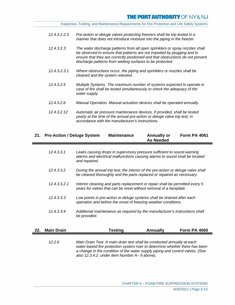
Inspection, Testing, and Maintenance Requirements for Fire Protection and Life Safety Systems
CHAPTER 6 – FOAM FIRE SUPPRESSION SYSTEMS 9/30/2011 | Page 6-13
12.4.3.2.2.3 Pre-action or deluge valves protecting freezers shall be trip tested in a manner that does not introduce moisture into the piping in the freezer.
12.4.3.2.3 The water discharge patterns from all open sprinklers or spray nozzles shall
be observed to ensure that patterns are not impeded by plugging and to ensure that they are correctly positioned and that obstructions do not prevent discharge patterns from wetting surfaces to be protected.
12.4.3.2.3.1 Where obstructions occur, the piping and sprinklers or nozzles shall be
cleaned and the system retested.
12.4.3.2.5 Multiple Systems. The maximum number of systems expected to operate in case of fire shall be tested simultaneously to check the adequacy of the water supply.
12.4.3.2.6 Manual Operation. Manual actuation devices shall be operated annually.
12.4.3.2.12 Automatic air pressure maintenance devices, if provided, shall be tested
yearly at the time of the annual pre-action or deluge valve trip test, in accordance with the manufacturer’s instructions.
21. Pre-Action / Deluge System Maintenance Annually or
As Needed Form PA 4061
12.4.3.3.1 Leaks causing drops in supervisory pressure sufficient to sound warning
alarms and electrical malfunctions causing alarms to sound shall be located and repaired.
12.4.3.3.2 During the annual trip test, the interior of the pre-action or deluge valve shall
be cleaned thoroughly and the parts replaced or repaired as necessary.
12.4.3.3.2.1 Interior cleaning and parts replacement or repair shall be permitted every 5 years for valves that can be reset without removal of a faceplate.
12.4.3.3.3 Low points in pre-action or deluge systems shall be drained after each
operation and before the onset of freezing weather conditions.
12.4.3.3.4 Additional maintenance as required by the manufacturer’s instructions shall be provided.
22. Main Drain Testing Annually Form PA 4060
12.2.6 Main Drain Test. A main drain test shall be conducted annually at each water-based fire protection system riser to determine whether there has been a change in the condition of the water supply piping and control valves. (See also 12.3.4.2. under Item Number A– 9 above).

Inspection, Testing, and Maintenance Requirements for Fire Protection and Life Safety Systems
CHAPTER 6 – FOAM FIRE SUPPRESSION SYSTEMS 9/30/2011 | Page 6-14
12.3.3.4 A main drain test shall be conducted annually at each system riser and any
time the valve is closed at each system riser or feed main after the control valve has been closed to determine whether there has been a change in the condition of the water supply piping and control valves.
23. Main Drain Testing Quarterly Form PA 4059
12.2.6.1 Systems where the sole water supply is through a backflow preventer and/or pressure reducing valves, the main drain test of at least one system downstream of the device shall be conducted on a quarterly basis.
24. Detection System Inspection,
Testing, Maintenance
As Required See Chapter 11
11.2.2 Automatic detection equipment shall be inspected, tested, and maintained in
accordance with NFPA 72®, National Fire Alarm Code®, to ensure that the detectors are in place, securely fastened, and protected from corrosion, weather, and mechanical damage and that the communication wiring, control panels, or pneumatic tubing system is functional.
25. Proportioning System(s) – All Testing Annually Form PA 4060
A 11.2.9 Proportioning systems might or might not include foam concentrate pumps. If pumps are a part of the proportioning system, the driver, pump, and gear reducer should be checked in accordance with the manufacturer's recommendations, and the check can include items such as lubrication, fuel, filters, oil levels, and clutches.
11.2.9.2 Valves specified to be checked shall include verification that the quantity of
foam concentrate satisfies the requirements of the original design.
11.2.9.3 The position (open or closed) of valves shall be verified in accordance with specified operating conditions.
11.2.9.4 Inspection of the concentrate tank shall include verification that the quantity
of foam concentrate satisfies the requirements of the original design. 26. Foam-Water System(s) Testing Annually Form PA 4060
11.3.3.1 Operation tests shall be conducted to ensure that the foam-water system(s) responds as designed, both automatically and manually.
11.3.3.2 The test procedure shall simulate anticipated emergency events so the
response of the foam-water system(s) can be evaluated.

Inspection, Testing, and Maintenance Requirements for Fire Protection and Life Safety Systems
CHAPTER 6 – FOAM FIRE SUPPRESSION SYSTEMS 9/30/2011 | Page 6-15
11.3.3.3 Where discharge from the system, discharge devices would create a
hazardous condition or conflict with local requirements, an approved alternate method to achieve full flow conditions shall be permitted.
11.3.3.4 Response Time. Under test conditions, the automatic fire detection systems,
when exposed to a test source, shall operate within the requirements of NFPA 72, National Fire Alarm Code, for the type of detector provided and the response time shall be recorded.
11.3.3.5 Discharge Time. The time lapse between operation of detection systems
and water delivery time to the protected area shall be recorded for open discharge devices.
11.3.3.7.1 Pressure readings shall be recorded at the highest, most remote discharge
device.
11.3.3.7.2 A second pressure reading shall be recorded at the main control valve.
11.3.3.7.3 Readings shall be compared to the hydraulic design pressures to ensure the original system design requirements are met.
11.3.4 Multiple Systems. The maximum number of systems expected to operate in
case of fire shall be tested simultaneously to check the adequacy of the water supply and concentrate pump.
27. Foam-Water Solution Testing Annually Form PA 4060
11.3.6 During the full flow foam test, a foam sample shall be taken.
11.3.6.2 This sample shall be checked by refractometric or other methods to verify concentration of the solution.
11.3.6.3 Concentration shall be within 10 percent of the acceptance test results but in
no case more than 10 percent below minimum design standards. 28. Manual Actuation Device(s) Testing Annually Form PA 4060 11.3.5 Manual actuation devices shall be tested annually. 29. Foam Concentrate Pump
Operation Maintenance Monthly Form PA 4062
11.4.6 Standard Balanced Pressure Proportioner.
(A) The foam concentrate pump shall be operated. Foam concentrate shall be circulated back to the tank.
11.4.7 In-Line Balanced Pressure Proportioner.

Inspection, Testing, and Maintenance Requirements for Fire Protection and Life Safety Systems
CHAPTER 6 – FOAM FIRE SUPPRESSION SYSTEMS 9/30/2011 | Page 6-16
(A) The foam concentrate pump shall be operated. Foam concentrate
shall be circulated back to the tank. 30. Foam Concentrate Samples Maintenance Annually Form PA 4061
11.2.10 Foam Concentrate Samples. Samples shall be submitted in accordance with the manufacturer’s recommended sampling procedures.
31. Proportioning System(s)
Standard Pressure Type Maintenance 5 Years Form PA 4063
Ball Drip (Automatic Type) Drain Valves
11.4.3 (A) The ball drip (automatic type) drain valves shall be disassembled, cleaned,
and re-assembled. 32. Proportioning System(s)
Standard Pressure Type Maintenance 10 Years Form PA 4064
Foam Concentrate Tank – Drain and Flush
11.4.3 (B) The foam liquid storage tank shall be drained of foam liquid and flushed.
(Foam liquid shall be permitted to be salvaged and reused).
Corrosion and Hydrostatic Test
11.4.3 (C) The foam liquid tank shall be inspected for internal and external corrosion and hydrostatically tested to the specified working pressure.
33. Proportioning System(s)
Bladder Tank Type Maintenance 10 Years Form PA 4064
Sight Glass
11.4.4 (A) Sight glass, where provided, shall be removed and cleaned.
Foam Concentrate Tank – Hydrostatic Test
11.4.4 (B) The foam concentrate tank shall be hydrostatically tested to the specified
working pressure.

Inspection, Testing, and Maintenance Requirements for Fire Protection and Life Safety Systems
CHAPTER 6 – FOAM FIRE SUPPRESSION SYSTEMS 9/30/2011 | Page 6-17
34. Proportioning System(s)
Line Type Maintenance 10 Years Form PA 4064
Foam Concentrate Tank – Corrosion and Pickup Pipes
11.4.5 (A) The foam concentrate tank shall be inspected for internal corrosion. Pickup
pipes inside the tank shall be inspected for corrosion, separation, or plugging.
Foam Concentrate Tank – Drain and Flush
11.4.5 (B) The foam concentrate tank shall be drained and flushed. (Foam concentrate
shall be permitted to be salvaged and reused. 35. Proportioning System(s)
Standard Balanced Pressure TypeMaintenance 5 Years Form PA 4063
Foam Concentrate Pump(s)
11.4.6 (B) Foam pumps, drive train, and drivers shall be serviced in accordance with
the manufacturer’s instructions and frequency, but not at intervals of more than 5 years.
Balancing Valve Diaphragm
11.4.6 (C) The diaphragm balancing valve shall be flushed through the diaphragm
section with water or foam concentrate until fluid appears clear or new. 36. Proportioning System(s)
Standard Balanced Pressure Type Maintenance 10 Years Form PA 4064
Foam Concentrate Tank
11.4.6 (D) The foam concentrate tank shall be inspected internally for corrosion and
sediment. Excessive sediment shall require draining and flushing of the tank. 37. Proportioning System(s)
In-Line Balanced Pressure Type Maintenance 5 Years Form PA 4063
Foam Concentrate Pump(s)
11.4.7 (B) Foam pumps, drive train, and drivers shall be serviced in accordance with
the manufacturer’s instructions and frequency, but not at intervals of more than 5 years.

Inspection, Testing, and Maintenance Requirements for Fire Protection and Life Safety Systems
CHAPTER 6 – FOAM FIRE SUPPRESSION SYSTEMS 9/30/2011 | Page 6-18
Balancing Valve Diaphragm
11.4.7 (C) The diaphragm balancing valve shall be flushed through the diaphragm
section with water of foam concentrate until fluid appears clear or new. 38. Proportioning System(s)
In-Line Balanced Pressure Type Maintenance 10 Years Form PA 4064
Foam Concentrate Tank
11.4.7 (D) The foam concentrate tank shall be inspected internally for corrosion and
sediment. Excessive sediment shall require draining and flushing of the tank. 39. Pressure Vacuum Vents Maintenance 5 Years Form PA 4063
11.4.8 Pressure Vacuum Vents.
The procedures specified below shall be performed every 5 Years. (A) The vent shall be removed from the expansion dome. While the
vent is removed, it shall be ensured that the opening is not blocked and that dirt or other foreign objects do not enter the tank.
(B) The vent bonnet shall be removed. The vacuum valve and pressure valve shall be lifted out.
(C) The vent body shall be flushed internally and the vacuum valve and the pressure valve shall be washed thoroughly. It shall be ensured that the screen is not clogged, and the use of any hard, pointed objects to clear the screen shall be avoided.
(D) If the liquid has become excessively gummy or solidified, the vent body and parts shall be soaked in hot soapy water.
(E) The vent body shall be turned upside down and drained thoroughly. Parts shall be dried by placing them in a warm and dry area or by using an air hose.
(F) Parts shall be sprayed with a light Teflon® coating, and the vent shall be reassembled. The use of any type of oil for lubrication purposes shall be avoided, as oil is harmful to the foam liquid.
(G) The vent bonnet shall be replaced, and the vent shall be turned upside down slowly a few times to ensure proper freedom of the movable parts.
(H) The vent shall be attached to the liquid storage tank expansion dome.
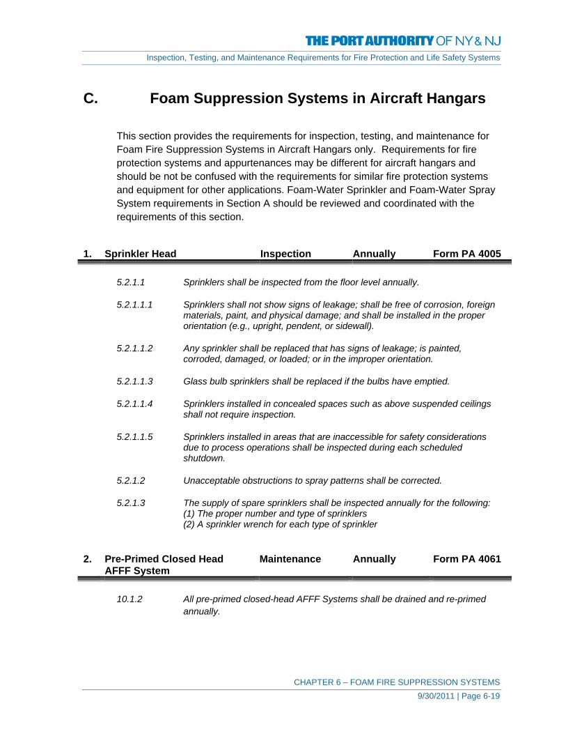
Inspection, Testing, and Maintenance Requirements for Fire Protection and Life Safety Systems
CHAPTER 6 – FOAM FIRE SUPPRESSION SYSTEMS 9/30/2011 | Page 6-19
C. Foam Suppression Systems in Aircraft Hangars
This section provides the requirements for inspection, testing, and maintenance for Foam Fire Suppression Systems in Aircraft Hangars only. Requirements for fire protection systems and appurtenances may be different for aircraft hangars and should be not be confused with the requirements for similar fire protection systems and equipment for other applications. Foam-Water Sprinkler and Foam-Water Spray System requirements in Section A should be reviewed and coordinated with the requirements of this section.
1. Sprinkler Head Inspection Annually Form PA 4005
5.2.1.1 Sprinklers shall be inspected from the floor level annually.
5.2.1.1.1 Sprinklers shall not show signs of leakage; shall be free of corrosion, foreign materials, paint, and physical damage; and shall be installed in the proper orientation (e.g., upright, pendent, or sidewall).
5.2.1.1.2 Any sprinkler shall be replaced that has signs of leakage; is painted,
corroded, damaged, or loaded; or in the improper orientation.
5.2.1.1.3 Glass bulb sprinklers shall be replaced if the bulbs have emptied.
5.2.1.1.4 Sprinklers installed in concealed spaces such as above suspended ceilings shall not require inspection.
5.2.1.1.5 Sprinklers installed in areas that are inaccessible for safety considerations
due to process operations shall be inspected during each scheduled shutdown.
5.2.1.2 Unacceptable obstructions to spray patterns shall be corrected.
5.2.1.3 The supply of spare sprinklers shall be inspected annually for the following:
(1) The proper number and type of sprinklers (2) A sprinkler wrench for each type of sprinkler
2. Pre-Primed Closed Head
AFFF System Maintenance Annually Form PA 4061
10.1.2 All pre-primed closed-head AFFF Systems shall be drained and re-primed
annually.

Inspection, Testing, and Maintenance Requirements for Fire Protection and Life Safety Systems
CHAPTER 6 – FOAM FIRE SUPPRESSION SYSTEMS 9/30/2011 | Page 6-20
3. Piping / Piping Hangers Inspection Annually Form PA 4005
5.2.2 Pipe and Fittings. Sprinkler pipe and fittings shall be inspected annually from the floor level.
5.2.2.1 Pipe and fittings shall be in good condition and free of mechanical damage,
leakage, corrosion, and misalignment.
5.2.2.2 Sprinkler piping shall not be subjected to external loads by materials either resting on the pipe or hung from the pipe.
5.2.2.3 Pipe and fittings installed in concealed spaces such as above suspended
ceilings shall not require inspection.
5.2.2.4 Pipe installed in areas that are inaccessible for safety considerations due to process operations shall be inspected during each scheduled shutdown.
4. Piping Testing 5 Years Form PA 4063
The operational test with actual discharge conducted is in conjunction with full discharge test of the system.
5. Sprinkler Alarm Valve –
Exterior Inspection Monthly Form PA 4002
12.4.1.1 Alarm valves shall be externally inspected monthly and shall verify the
following: (1) The gauges indicate normal supply water pressure is being
maintained. (2) The valve is free of physical damage. (3) All valves are in the appropriate open or closed position. (4) The retarding chamber or alarm drains are not leaking.
6. Sprinkler Alarm Valve Testing Quarterly Form PA 4003
The operational test conducted is the same as for wet sprinkler system alarm valves listed below. As identified, for the purposes of this test, the inspector’s flow valve is acceptable.
5.3.3.1 Water-flow devices including, but not limited to, mechanical water motor
gongs and pressure switch type shall be tested quarterly.
5.3.3.3 Testing the water-flow alarms on wet pipe systems shall be accomplished by opening the inspector’s test connection.
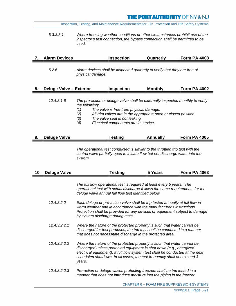
Inspection, Testing, and Maintenance Requirements for Fire Protection and Life Safety Systems
CHAPTER 6 – FOAM FIRE SUPPRESSION SYSTEMS 9/30/2011 | Page 6-21
5.3.3.3.1 Where freezing weather conditions or other circumstances prohibit use of the inspector’s test connection, the bypass connection shall be permitted to be used.
7. Alarm Devices Inspection Quarterly Form PA 4003
5.2.6 Alarm devices shall be inspected quarterly to verify that they are free of physical damage.
8. Deluge Valve – Exterior Inspection Monthly Form PA 4002
12.4.3.1.6 The pre-action or deluge valve shall be externally inspected monthly to verify the following: (1) The valve is free from physical damage. (2) All trim valves are in the appropriate open or closed position. (3) The valve seat is not leaking. (4) Electrical components are in service.
9. Deluge Valve Testing Annually Form PA 4005
The operational test conducted is similar to the throttled trip test with the control valve partially open to initiate flow but not discharge water into the system.
10. Deluge Valve Testing 5 Years Form PA 4063
The full flow operational test is required at least every 5 years. The operational test with actual discharge follows the same requirements for the deluge valve annual full flow test identified below.
12.4.3.2.2 Each deluge or pre-action valve shall be trip tested annually at full flow in
warm weather and in accordance with the manufacturer’s instructions. Protection shall be provided for any devices or equipment subject to damage by system discharge during tests.
12.4.3.2.2.1 Where the nature of the protected property is such that water cannot be
discharged for test purposes, the trip test shall be conducted in a manner that does not necessitate discharge in the protected area.
12.4.3.2.2.2 Where the nature of the protected property is such that water cannot be
discharged unless protected equipment is shut down (e.g., energized electrical equipment), a full flow system test shall be conducted at the next scheduled shutdown. In all cases, the test frequency shall not exceed 3 years.
12.4.3.2.2.3 Pre-action or deluge valves protecting freezers shall be trip tested in a
manner that does not introduce moisture into the piping in the freezer.
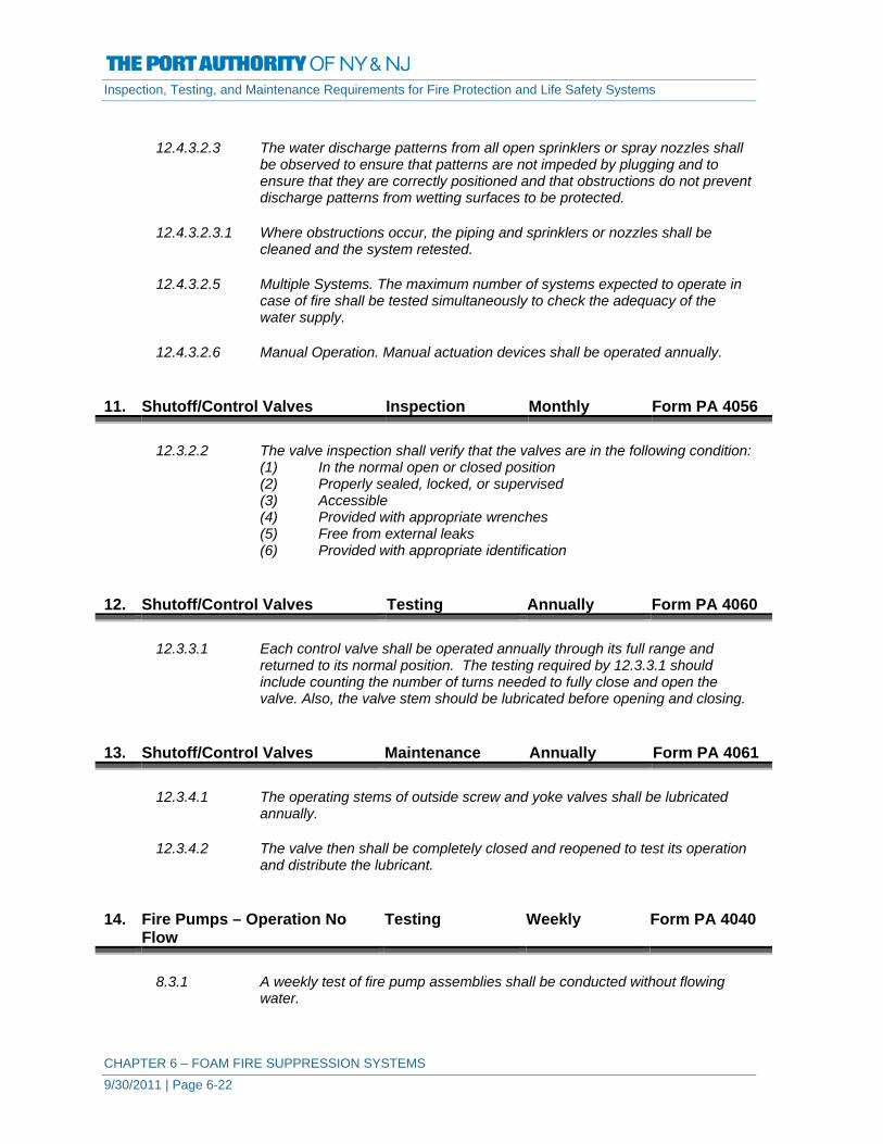
Inspection, Testing, and Maintenance Requirements for Fire Protection and Life Safety Systems
CHAPTER 6 – FOAM FIRE SUPPRESSION SYSTEMS 9/30/2011 | Page 6-22
12.4.3.2.3 The water discharge patterns from all open sprinklers or spray nozzles shall
be observed to ensure that patterns are not impeded by plugging and to ensure that they are correctly positioned and that obstructions do not prevent discharge patterns from wetting surfaces to be protected.
12.4.3.2.3.1 Where obstructions occur, the piping and sprinklers or nozzles shall be
cleaned and the system retested.
12.4.3.2.5 Multiple Systems. The maximum number of systems expected to operate in case of fire shall be tested simultaneously to check the adequacy of the water supply.
12.4.3.2.6 Manual Operation. Manual actuation devices shall be operated annually.
11. Shutoff/Control Valves Inspection Monthly Form PA 4056
12.3.2.2 The valve inspection shall verify that the valves are in the following condition: (1) In the normal open or closed position (2) Properly sealed, locked, or supervised (3) Accessible (4) Provided with appropriate wrenches (5) Free from external leaks (6) Provided with appropriate identification
12. Shutoff/Control Valves Testing Annually Form PA 4060
12.3.3.1 Each control valve shall be operated annually through its full range and returned to its normal position. The testing required by 12.3.3.1 should include counting the number of turns needed to fully close and open the valve. Also, the valve stem should be lubricated before opening and closing.
13. Shutoff/Control Valves Maintenance Annually Form PA 4061
12.3.4.1 The operating stems of outside screw and yoke valves shall be lubricated annually.
12.3.4.2 The valve then shall be completely closed and reopened to test its operation
and distribute the lubricant. 14. Fire Pumps – Operation No
Flow Testing Weekly Form PA 4040
8.3.1 A weekly test of fire pump assemblies shall be conducted without flowing
water.

Inspection, Testing, and Maintenance Requirements for Fire Protection and Life Safety Systems
CHAPTER 6 – FOAM FIRE SUPPRESSION SYSTEMS 9/30/2011 | Page 6-23
8.3.1.1 This test shall be conducted by starting the pump automatically.
8.3.1.2 The electric pump shall run a minimum of 10 minutes.
8.3.1.3 The diesel pump shall run a minimum of 30 minutes.
8.3.1.4 A valve installed to open as a safety feature shall be permitted to discharge
water.
8.3.1.5 The automatic weekly test times shall be permitted to be substituted for the starting procedure.
8.3.2.2 The pertinent visual observations or adjustments specified in the following
checklists shall be conducted while the pump is running.
1) Pump System Procedure: a) Record the system suction and discharge pressure gauge readings. b) Check pump packing glands for flight discharge c) Adjust gland nuts, if necessary d) Check for unusual noise or vibration e) Check packing boxes, bearings or pump casing for overheating f) Record the pump starting pressure
2) Electrical System Procedure:
a) Observe the time for motor to accelerate to full speed b) Record the time controller is on first step (for reduced voltage or
reduce current) c) Record the time pump runs after starting (for automatic stop
controller).
1) Diesel Engine System Procedure: a) Observe the time for engine to crank b) Observe the time for engine to reach running speed c) Observe the engine oil pressure gauge, speed indicator water, and oil
temperature indicators periodically while engine is running d) Record any abnormalities e) Check the heat exchanger for cooling water flow
15. Fire Pumps – Operation Flow
Condition Testing Annually Forms PA
4042, 4043
8.3.3.1 An annual test of each pump assembly shall be conducted under minimum, rated, and peak flows of the fire pump by controlling the quantity of water discharged through approved test devices.
8.3.3.1.2.1 Use of the Pump Discharge Via the Hose Streams. Pump suction and
discharge pressures and the flow measurements of each hose stream shall determine the total pump output. Care shall be taken to prevent water damage by verifying there is adequate drainage for the high-pressure water discharge from hoses.

Inspection, Testing, and Maintenance Requirements for Fire Protection and Life Safety Systems
CHAPTER 6 – FOAM FIRE SUPPRESSION SYSTEMS 9/30/2011 | Page 6-24
8.3.3.1.2.2 Use of the Pump Discharge Via the Bypass Flowmeter to Drain or Suction
the Reservoir. Pump suction and discharge pressures and the flowmeter measurements shall determine to total pump output.
8.3.3.1.2.3 Use of the Pump Discharge Via the Bypass Flowmeter to Pump Suction
(Closed-Loop Metering). Pump suction and discharge pressures and the flowmeter measurements shall determine the total pump output.
8.3.3.1.3 Where the annual test is conducted periodically in accordance with
8.3.3.1.2.3, a test shall be conducted every 3 years in accordance with 8.3.3.1.2.1 or 8.3.3.1.2.2 in lieu of the method described in 8.3.3.1.2.3.
8.3.3.1.4 Where 8.3.3.1.2.2 or 8.3.3.1.2.3 is used, the flow meter shall be adjusted
immediately prior to conducting the test in accordance with the manufacturer’s instructions. If the test results are not consistent with the previous annual test, 8.3.3.1.2.1 shall be used. If testing in accordance with 8.3.3.1.2.1 is not possible, a flowmeter calibration shall be performed and the test shall be repeated.
8.3.3.2 The pertinent visual observations, measurements, and adjustments specified
in the following checklists shall be conducted annually while the pump is running and flowing water under the specified output condition:
1) At no-flow condition (churn):
a) Check the circulation relief valve for operation to discharge water b) Check the pressure relief valve (if installed) for proper operation c) Continue the test for ½ hour
2) At each flow condition:
a) Record the electric motor voltage and current (all lines) b) Record the pump speed in rpm c) Record the simultaneous (approximately) readings of pump
suction and discharge pressures and pump discharge flow
8.3.3.3 For installations having a pressure relief valve, the operation of the relief valve shall be closely observed during each flow condition to determine if the pump discharge pressure exceeds the normal operating pressure of the system components.
8.3.3.3.1 The pressure relief valve shall also be observed during each flow condition to
determine if the pressure relief valve closes at the proper pressure.
8.3.3.3.2 A pressure relief valve that is open during a flow condition will affect test results.
8.3.3.7 Suction Screens. After the water-flow portions of the annual test or fire
protection system activations, the suction screens shall be inspected and cleared of any debris or obstructions.

Inspection, Testing, and Maintenance Requirements for Fire Protection and Life Safety Systems
CHAPTER 6 – FOAM FIRE SUPPRESSION SYSTEMS 9/30/2011 | Page 6-25
16. Water Reservoirs Inspection Monthly Form PA 4046
9.2.1.2 Tanks not equipped with supervised water level alarms that are connected to a constantly attended location shall be inspected monthly.
9.4.1 The tank shall be maintained full or at the designed water level.
The water level should never be lower than 76 mm to 102 mm (3 in. to 4 in.) below the designated fire service level.
17. Hose Stations Inspection Monthly Form PA 4062 Cap missing Replace Fire hose connection damaged Repair Valve handles missing Replace Cap gaskets missing or deteriorated Replace Valve leaking Close or Repair Visible obstructions Remove Restricting device missing Replace 18. Hand Hose Stations Testing 5 Years Form PA 4063
An operational test with actual discharge is required for all hose stations and may be conducted is in conjunction with full discharge test of the system..
19. Strainers Inspection Annually Form PA 4058 20. Foam Concentrate Maintenance Annually Form PA 4061
11.2.10 Samples shall be submitted in accordance with the manufacturer’s recommended sampling procedures.
21. Concentrate Storage Tanks Inspection Monthly Form PA 4056
11.2.9.4 Inspection of the concentrate tank shall include verification that the quantity of foam concentrate satisfies the requirements of the original design.

Inspection, Testing, and Maintenance Requirements for Fire Protection and Life Safety Systems
CHAPTER 6 – FOAM FIRE SUPPRESSION SYSTEMS 9/30/2011 | Page 6-26
22. Concentrate Pump Testing Weekly Form PA 4055
A functional test without discharge is required. 23. Concentrate Pump Testing Annually Form PA 4060
An operational test with flow but not discharging into the system is conducted.
24. Concentrate Pump Testing 5 Years Form PA 4063
The operational test with actual discharge conducted is in conjunction with full discharge test of the system.
25. Concentrate Control Valve
(Automatic) Inspection Monthly Form PA 4056
11.2.9.3 The position (open or closed) of valves shall be verified in accordance with
specified operating conditions. 26. Concentrate Control Valve
(Automatic) Testing Annually Form PA 4060
An operational test with flow but not discharging into the system is conducted where the automatic concentrate control valve is operated through its full range and returned to its normal position.
27. Concentrate Control Valve
(Automatic) Testing 5 Years Form PA 4063
The operational test with actual discharge conducted is in conjunction with full discharge test of the system.
28. Concentrate Shutoff/
Control Valve Inspection Monthly Form PA 4056
11.2.9.3 The position (open or closed) of valves shall be verified in accordance with
specified operating conditions.

Inspection, Testing, and Maintenance Requirements for Fire Protection and Life Safety Systems
CHAPTER 6 – FOAM FIRE SUPPRESSION SYSTEMS 9/30/2011 | Page 6-27
29. Concentrate Shutoff/ Control Valve
Testing Annually Form PA 4060
An functional test without discharge into the system is conducted where the concentrate shutoff valve is operated through its full range and returned to its normal position.
30. Foam Proportioning Device Inspection Monthly Form PA 4056
11.2.9.5.1 Standard Pressure Proportioner. This is a pressure vessel. The pressure shall be removed before the inspection to prevent injury. The inspection shall verify the following:
1) Ball drip valves (automatic drains) are free and opened 2) External corrosion on foam concentrate storage tanks is not present
11.2.9.5.2 Bladder Tank Proportioner. This is a pressure vessel. The pressure shall
be removed before the inspection of present injury. The inspection shall include the following: 1) Water control valves to foam concentrate tank 2) A check for external corrosion on foam concentrate storage tanks 3) A check for the presence of foam in the water surrounding the
bladder (annual)
11.2.9.5.3 Line Proportioner. The inspection shall include the following: 1) Strainers 2) Verification that pressure vacuum vent is operating freely 3) A check for external corrosion on foam concentrate storage tanks
11.2.9.5.4 Standard Balanced Pressure Proportioner. The inspection shall include
the following: 1) Strainers 2) Verification that pressure vacuum vent is operating freely 3) Verification that gauges are in good operating condition 4) Verification that sensing line valves are open 5) Verification that power is available to foam liquid pump
11.2.9.5.5 In-Line Balanced Pressure Proportioner. The inspection shall include the
following: 1) Strainers 2) Verification that pressure vacuum vent is operating freely 3) Verification that gauges are in good working condition 4) Verification that sensing line valves at pump unit and individual
proportioner stations are open 5) Verification that power is available to foam liquid pump
11.2.9.5.6 Orifice Plate Proportioner. The inspection shall include the following:
1) Strainers 2) Verification that pressure vacuum vent is operating freely 3) Verification that gauges are in good working condition 4) Verification that power is available to foam liquid pump

Inspection, Testing, and Maintenance Requirements for Fire Protection and Life Safety Systems
CHAPTER 6 – FOAM FIRE SUPPRESSION SYSTEMS 9/30/2011 | Page 6-28
31. Foam Proportioning Device Testing 5 Years Form PA 4063
The operational test with actual discharge conducted is in conjunction with full discharge test of the system.
32. Water Powered Monitor
Nozzle Inspection Monthly Form PA 4062
33. Water Powered Monitor
Nozzle Testing Annually Form PA 4060
The operational test with actual discharge conducted demonstrates the full motion of the nozzle.
34. Electric Powered Manual
Nozzle Inspection Monthly Form PA 4062
35. Electric Powered Manual
Nozzle Testing Annually Form PA 4060
The functional test without discharge conducted demonstrates the full motion of the nozzle.
36. Electric Powered Manual
Nozzle Testing 5 Years Form PA 4063
The operational test with actual discharge required can be done in conjunction with full discharge test of the system.
37. Water Powered High
Expansion Foam Generator Inspection Monthly Form PA 4056

Inspection, Testing, and Maintenance Requirements for Fire Protection and Life Safety Systems
CHAPTER 6 – FOAM FIRE SUPPRESSION SYSTEMS 9/30/2011 | Page 6-29
38. Water Powered High
Expansion Foam Generator Testing Annually Form PA 4060
An operational test with flow but not discharging is conducted from each foam generator.
39. Water Powered High
Expansion Foam Generator Testing 5 Years Form PA 4063
The operational test with actual discharge required is in conjunction with full discharge test of the system.
40. Electric Powered High
Expansion Foam Generator Inspection Monthly Form PA 4056
41. Electric Powered High
Expansion Foam Generator Testing Annually Form PA 4060
A functional test without discharge is required for each foam generator.
42. Electric Powered High
Expansion Foam Generator Testing 5 Years Form PA 4063
The operational test with actual discharge required is in conjunction with full discharge test of the system.
43. Pneumatic Detector Testing Semi-
Annually Form PA 4065
A test demonstrating satisfactory pneumatic detector system operation is required.
44. Pneumatic Detector Testing Annually Form PA 4065
A satisfactory test of the pneumatic detector system is required demonstrating operation of all fire protection system functions including activation of the deluge valve with flow but not discharging into the system. This test can be conducted in conjunction with the annual test required in B.9 above.

Inspection, Testing, and Maintenance Requirements for Fire Protection and Life Safety Systems
CHAPTER 6 – FOAM FIRE SUPPRESSION SYSTEMS 9/30/2011 | Page 6-30
Check that the set points are the same as the original. 45. Electric Detector Testing Semi-
Annually Form PA 4065
A test demonstrating satisfactory electric detector system operation is required.
46. Electric Detector Testing Annually Form PA 4065
A satisfactory test of the electric detector system is required demonstrating operation of all fire protection system functions including activation of the deluge valve with flow but not discharging into the system. This test can be conducted in conjunction with the annual test required in #9 above.
Check that the set points are the same as the original.
47. Optical Detector Inspection Weekly Form PA 4055 48. Optical Detector Testing Semi-
Annually Form PA 4065
A test demonstrating satisfactory optical detector system operation is required.
49. Optical Detector Testing Annually Form PA 4065
A satisfactory test of the optical detector system is required demonstrating operation of all fire protection system functions including activation of the deluge valve with flow but not discharging into the system. This test can be conducted in conjunction with the annual test required in #9 above.
Check that the set points are the same as the original.
50. Control Panels Inspection Monthly Form PA 4062

Inspection, Testing, and Maintenance Requirements for Fire Protection and Life Safety Systems
CHAPTER 6 – FOAM FIRE SUPPRESSION SYSTEMS 9/30/2011 | Page 6-31
51. Control Panels Testing Semi-
Annually Form PA 4065
The functional test without flow or discharge is intended to show operation of all fire protection system functions.
52. Control Panels Testing Annually Form PA 4065
A satisfactory test demonstrates operation of all fire protection system functions including activation of the deluge valve with flow but not discharging into the system. This test can be conducted in conjunction with the annual test required in #9 above.
53. Alarm Transmission (Local
and Remote) Testing Monthly Form PA 4062
The functional test without discharge conducted is intended to show transmission of selected circuits demonstrating continued operation of the system. Testing should be planned to include all circuits on an annual basis.
At a minimum, control equipment shall be tested to verify correct receipt of alarm, supervisory, and trouble signals (inputs), operation of evacuation signals and auxiliary functions (outputs), circuit supervision including detection of open circuits and ground faults, and power supply supervision for detection of loss of ac power and disconnection of secondary batteries.
54. Tamper Switch Testing Quarterly Form PA 4059
The functional test without discharge conducted is in conformance with the requirements below with the exception that the test is conducted quarterly and not semi-annually.
12.3.3.5.1 Valve supervisory switches shall be tested semiannually.
12.3.3.5.2 A distinctive signal shall indicate movement from the valve’s normal position
during either the first two revolutions of a hand wheel or when the stem of the valve has moved one-fifth of the distance from its normal position.
12.3.3.5.3 The signal shall not be restored at any valve position except the normal
position. 55. Flow Indication Switch Testing Annually Form PA 4065
With the exception of the waterflow switch for the sprinkler alarm valve, any other device intended to indicate flow through the system shall be operationally tested with flow but not discharging into the system.

Inspection, Testing, and Maintenance Requirements for Fire Protection and Life Safety Systems
CHAPTER 6 – FOAM FIRE SUPPRESSION SYSTEMS 9/30/2011 | Page 6-32
56. Supervisory Alarms Testing Semi-
Annually Form PA 4065
With the exception of the valve tamper switch requirement identified above, all other supervisory alarms shall be functionally tested without discharging the system including but not limited to high and low air pressure switches, room temperature switches, water level switches, Primary (main) power supply, etc.
57. Manual Actuation Stations Testing Semi-
Annually Form PA 4065
A functional test without discharge is required for all fire suppression system manual activation stations.
58. Hangar Floor Drain Sys. &
Separators Inspection Monthly Form PA 4062
The inspection must include all components of the hangar floor drainage system and separators. Floor trench drainage systems may be installed to effectively dispose of water used for cleaning aircraft and hangar floor surfaces and water accumulation from possible flooding due to high groundwater tables, and to drain away water discharged from the fire protection equipment provided within the structure.
59. Hangar Floor Drain Sys. &
Separators Testing 5 Years Form PA 4063
The operational test with actual discharge required is in conjunction with full discharge test of the system.
60. Gas Detectors Inspection Monthly Form PA 4062
The inspection must include all components of the gas detection system. 61. Gas Detectors Testing Semi-
Annually Form PA 4065
The functional test without discharging the system is conducted as prescribed by the manufacturer and as necessary for the application.
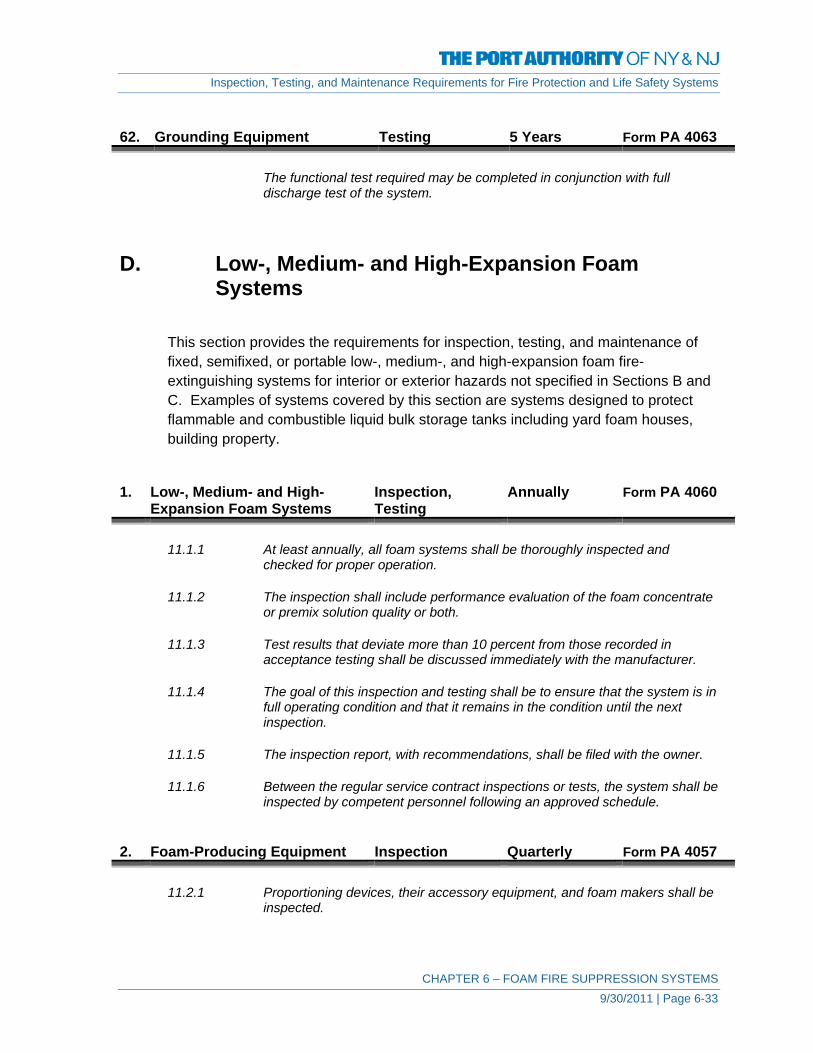
Inspection, Testing, and Maintenance Requirements for Fire Protection and Life Safety Systems
CHAPTER 6 – FOAM FIRE SUPPRESSION SYSTEMS 9/30/2011 | Page 6-33
62. Grounding Equipment Testing 5 Years Form PA 4063
The functional test required may be completed in conjunction with full discharge test of the system.
D. Low-, Medium- and High-Expansion Foam
Systems
This section provides the requirements for inspection, testing, and maintenance of fixed, semifixed, or portable low-, medium-, and high-expansion foam fire-extinguishing systems for interior or exterior hazards not specified in Sections B and C. Examples of systems covered by this section are systems designed to protect flammable and combustible liquid bulk storage tanks including yard foam houses, building property.
1. Low-, Medium- and High-
Expansion Foam Systems Inspection, Testing
Annually Form PA 4060
11.1.1 At least annually, all foam systems shall be thoroughly inspected and
checked for proper operation.
11.1.2 The inspection shall include performance evaluation of the foam concentrate or premix solution quality or both.
11.1.3 Test results that deviate more than 10 percent from those recorded in
acceptance testing shall be discussed immediately with the manufacturer.
11.1.4 The goal of this inspection and testing shall be to ensure that the system is in full operating condition and that it remains in the condition until the next inspection.
11.1.5 The inspection report, with recommendations, shall be filed with the owner.
11.1.6 Between the regular service contract inspections or tests, the system shall be
inspected by competent personnel following an approved schedule. 2. Foam-Producing Equipment Inspection Quarterly Form PA 4057
11.2.1 Proportioning devices, their accessory equipment, and foam makers shall be inspected.

Inspection, Testing, and Maintenance Requirements for Fire Protection and Life Safety Systems
CHAPTER 6 – FOAM FIRE SUPPRESSION SYSTEMS 9/30/2011 | Page 6-34
11.2.1.1 Fixed discharge outlets equipped with frangible seals shall be provided with suitable inspection means to permit proper maintenance and for inspection and replacement of vapor seals.
3. Piping – Aboveground Inspection Annually Form PA 4058
11.3.1 Aboveground piping shall be examined to determine its condition and to verify that proper drainage pitch is maintained.
11.3.2 Pressure tests of normally dry piping shall be made when visual inspection
indicates questionable strength due to corrosion or mechanical damage. 4. Piping – Underground Inspection 5 Years Form PA 4063
11.3.3 Underground piping shall be spot-checked for deterioration at least every 5 years.
5. Strainers Inspection,
Maintenance Annually Form PA 4060
11.4 Strainers shall be inspected periodically and shall be cleaned after each use
and flow test. 6. Control Valves – Sealed Inspection Weekly Form PA 4055
12.3.2.1 All valves shall be inspected weekly.
12.3.2.2 The valve inspection shall verify that the valves are in the following condition: 1) In the normal open or closed position 2) Properly sealed, locked, or supervised 3) Accessible 4) Provided with appropriate wrenches 5) Free from external leaks 6) Provided with appropriate identification
7. Control Valves –
Locked/Supervised Inspection Monthly Form PA 4056
12.3.2.1.1 Valves secured with locks or supervised in accordance with applicable NFPA
standards shall be permitted to be inspected monthly.
12.3.2.2 The valve inspection shall verify that the valves are in the following condition: 1) In the normal open or closed position 2) Properly sealed, locked, or supervised 3) Accessible
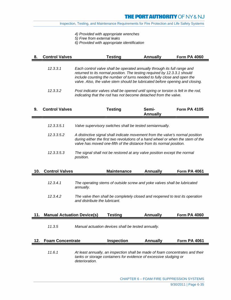
Inspection, Testing, and Maintenance Requirements for Fire Protection and Life Safety Systems
CHAPTER 6 – FOAM FIRE SUPPRESSION SYSTEMS 9/30/2011 | Page 6-35
4) Provided with appropriate wrenches 5) Free from external leaks 6) Provided with appropriate identification
8. Control Valves Testing Annually Form PA 4060
12.3.3.1 Each control valve shall be operated annually through its full range and returned to its normal position. The testing required by 12.3.3.1 should include counting the number of turns needed to fully close and open the valve. Also, the valve stem should be lubricated before opening and closing.
12.3.3.2 Post indicator valves shall be opened until spring or torsion is felt in the rod,
indicating that the rod has not become detached from the valve. 9. Control Valves Testing Semi-
Annually Form PA 4105
12.3.3.5.1 Valve supervisory switches shall be tested semiannually.
12.3.3.5.2 A distinctive signal shall indicate movement from the valve’s normal position
during either the first two revolutions of a hand wheel or when the stem of the valve has moved one-fifth of the distance from its normal position.
12.3.3.5.3 The signal shall not be restored at any valve position except the normal
position. 10. Control Valves Maintenance Annually Form PA 4061
12.3.4.1 The operating stems of outside screw and yoke valves shall be lubricated annually.
12.3.4.2 The valve then shall be completely closed and reopened to test its operation
and distribute the lubricant. 11. Manual Actuation Device(s) Testing Annually Form PA 4060
11.3.5 Manual actuation devices shall be tested annually. 12. Foam Concentrate Inspection Annually Form PA 4061
11.6.1 At least annually, an inspection shall be made of foam concentrates and their tanks or storage containers for evidence of excessive sludging or deterioration.

Inspection, Testing, and Maintenance Requirements for Fire Protection and Life Safety Systems
CHAPTER 6 – FOAM FIRE SUPPRESSION SYSTEMS 9/30/2011 | Page 6-36
11.6.2 Samples of concentrates shall be sent to the manufacturer or qualified laboratory for quality condition testing.
11.6.3 Quantity of concentrate in storage shall meet design requirements, and tanks
or containers shall normally be kept full, with space allowed for expansion.
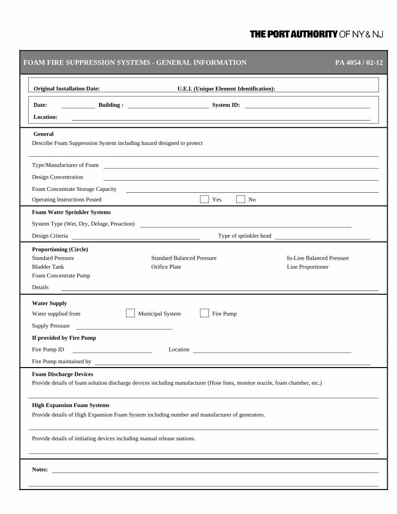
FOAM FIRE SUPPRESSION SYSTEMS - GENERAL INFORMATION PA 4054 / 02-12
Original Installation Date: U.E.I. (Unique Element Identification):
Date: Building : System ID:
Location:
General Describe Foam Suppression System including hazard designed to protect
Type/Manufacturer of Foam
Design Concentration
Foam Concentrate Storage Capacity
Operating Instructions Posted Yes No
Foam Water Sprinkler Systems
System Type (Wet, Dry, Deluge, Preaction)
Design Criteria Type of sprinkler head
Proportioning (Circle) Standard Pressure Standard Balanced Pressure In-Line Balanced Pressure Bladder Tank Orifice Plate Line Proportioner Foam Concentrate Pump
Details
Water Supply
Water supplied from Municipal System Fire Pump
Supply Pressure
If provided by Fire Pump
Fire Pump ID Location
Fire Pump maintained by
Foam Discharge Devices Provide details of foam solution discharge devices including manufacturer (Hose lines, monitor nozzle, foam chamber, etc.)
High Expansion Foam Systems Provide details of High Expansion Foam System including number and manufacturer of generators.
Provide details of initiating devices including manual release stations.
Notes:

FOAM FIRE SUPPRESSION SYSTEMS - WEEKLY INSPECTION PA 4055 / 02-12
Year: System:
Location:
1. If valves are sealed, note “yes” in this block. If any are not sealed, reseal and note “resealed” in this block.
2. Record any notes about the system that the inspector believes to be significant. Continue on reverse if necessary.
Date Inspector Valve(s) Sealed (1) Notes (2)
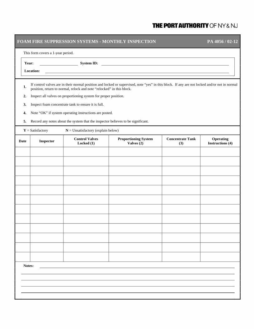
FOAM FIRE SUPPRESSION SYSTEMS - MONTHLY INSPECTION PA 4056 / 02-12
This form covers a 1-year period.
Year: System ID:
Location:
1. If control valves are in their normal position and locked or supervised, note “yes” in this block. If any are not locked and/or not in normal position, return to normal, relock and note “relocked” in this block.
2. Inspect all valves on proportioning system for proper position.
3. Inspect foam concentrate tank to ensure it is full.
4. Note “OK” if system operating instructions are posted.
5. Record any notes about the system that the inspector believes to be significant.
Y = Satisfactory N = Unsatisfactory (explain below)
Date Inspector Control Valves Locked (1)
Proportioning System Valves (2)
Concentrate Tank (3)
Operating Instructions (4)
Notes:

FOAM FIRE SUPPRESSION SYSTEMS - QUARTERLY INSPECTION PA 4057 / 02-12
This form covers a 1-year period.
Year: System ID: Location:
Y = Satisfactory N = Unsatisfactory (explain below)
Date
Inspector
Inspect foam concentrate strainers.
Inspect area beneath and surrounding foam system to assure adequate drainage.
Inspect system piping and fittings for corrosion, misalignment, trapped sections, low-point drains, condition of rubber-gasketed fittings.
Inspect hangers and supports for damage or missing parts, secure attachment to structural supports and piping, rust, corrosion, and missing or damaged protective coatings.
Deluge/Pre-action Valves Heating enclosure, heating equipment; low temperature alarms.
Notes:

FOAM FIRE SUPPRESSION SYSTEMS - ANNUAL INSPECTION PA 4058 / 02-12
Year: System:
Location:
Y = Satisfactory N = Unsatisfactory (explain below)
Date
Inspector
Foam Water Sprinklers
Assure they are free of corrosion, obstruction, foreign materials and physical damage.
Sprinkler Piping
Assure it is in good condition, free of damage, not corroded, not misaligned, and not subject to internal leaks.
Pipe Hangers and Seismic Braces
Assure they are neither damaged nor corroded.
Gauges
Assure they are in good condition and normal water pressures are maintained.
Deluge/Pre-action Valves
Inspect valves and condition of detection.
Notes:

FOAM FIRE SUPPRESSION SYSTEMS - QUARTERLY TESTS PA 4059 / 02-12
This form covers a 1-year period.
Year: System:
Location:
Date
Inspector
Main Drain Test
Record the static water supply pressure.
Open the main drain and allow water flow to stabilize.
Record the residual water supply pressure.
Close the main drain (slowly).
Flow Alarm
Test flow alarm by opening the test valve. Note “OK” in box if alarm operated properly.
Exercise Valves
Exercise all valves by fully closing and reopening. Replace locks or seals. Note “OK” in block if there are no problems.
Control Valves
Open all control valves until spring or tension is felt in the operating rod. Back valve 1/4 turn to prevent jamming.
Note: Outside screw and yoke (OS&Y) valves or gear-operated indicating butterfly valves do not require quarterly testing.
Notes
Record any notes about the system that the inspector believes to be significant. Place a number in this block and number the corresponding note below.
Notes:

FOAM FIRE SUPPRESSION SYSTEMS - ANNUAL TESTS AND MAINTENANCE PA 4060 / 02-12
Date: Inspector: System:
Location:
Y = Satisfactory N = Unsatisfactory (explain below)
Clean Strainer Ensure blow-down valve is closed and plugged.
Check Foam Concentration Take sample during trip test. Concentration should be within 10% of acceptance test results. Discharge Device Location and Position The discharge pattern from all of the open spray devices shall be observed to ensure that patterns are not impeded by plugged discharge devices and to ensure that discharge devices are correctly positioned.
Proportioning System(s)
Complete Foam-Water System
Foam-Water Solution - Concentration Testing
Manual Actuation Device Test
Control Valves
1. Operate through its full range and return to its normal position
2. Posts indicator valve shall be open until spring or torsion is felt in the rod, indicating that the rod has not
become detached from the valve. Note: Conduct this test every time the valve is closed.
3. Posts indicator and outside screw and yoke shall be backed a one-quarter turn from the fully open position to
prevent jamming.
4. A main drain test shall be conducted to verify that the control valve is in the open position after conducting the
above test.
Notes:

FOAM FIRE SUPPRESSION SYSTEMS - ANNUAL MAINTENANCE PA 4061 / 02-12
Date: Inspector: System:
Location:
Y = Satisfactory N = Unsatisfactory (explain below)
Exercise Valves Operate each control valve through its full range and return it to its normal position. Reseal or relock valves as appropriate.
Lubricate Valves Lubricate all valves with graphite or a mixture of light oil and graphite.
Foam Concentrate Samples Sample shall be submitted in accordance with manufacturer's recommended sampling procedures
Notes:

FOAM FIRE SUPPRESSION SYSTEMS - MONTHLY MAINTENANCE PA 4062 / 02-12
Date: Inspector: System:
Location:
Y = Satisfactory N = Unsatisfactory (explain below)
Foam Concentrate Pump Operation 1. Standard balanced pressure proportioner The foam concentrate pump shall be operated. Foam concentrate shall be circulated back to the tank
Foam Concentrate Pump Operation 1. In-line Balance pressure proportioner The foam concentrate pump shall be operated. Foam concentrate shall be circulated back to the tank
Notes:
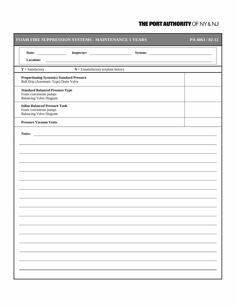
FOAM FIRE SUPPRESSION SYSTEMS - MAINTENANCE 5 YEARS PA 4063 / 02-12
Date: Inspector: System:
Location:
Y = Satisfactory N = Unsatisfactory (explain below)
Proportioning System(s) Standard Pressure Ball Drip (Automatic Type) Drain Valve
Standard Balanced Pressure Type Foam concentrate pumps Balancing Valve Diagram
Inline Balanced Pressure Tank Foam concentrate pumps Balancing Valve Diagram
Pressure Vacuum Vents
Notes:

FOAM FIRE SUPPRESSION SYSTEMS - MAINTENANCE 10- YEARS PA 4064 / 02-12
Date: Inspector: System:
Location:
Y = Satisfactory N = Unsatisfactory (explain below)
Proportioning System(s) Standard Pressure Type Foam Concentrate Tank - Drain and Flush Corrosion and Hydrostatic Test
Bladder Type Site Glass Foam Concentrate Tank-Hydrostatic Test
Line Type Foam Concentrate Tank - Corrosion and Pickup Pipes Foam Concentrate - Drain and Flush
Inline Balanced Pressure Tank Foam concentrate pumps
Notes:

Inspection, Testing, and Maintenance Requirements for Fire Protection and Life Safety Systems
CHAPTER 7 – CARBON DIOXIDE EXTINGUISHING SYSTEMS 9/30/2011 | Page 7-1
CHAPTER 7 – CARBON DIOXIDE EXTINGUISHING
SYSTEMS
DEFINITIONS Alarms and Indicators. Any device capable of providing audible, visual, or olfactory
indication. Cargo Space. A space for the carriage or storage of items or products that
are transported by the vessel. Electrical Equipment Space. A space containing electrical propulsion, power generating,
or power distribution equipment. Hand Hose Line System. A hose and nozzle assembly connected by fixed piping or
connected directly to a supply of extinguishing agent High Pressure. Indicates that the carbon dioxide is stored in pressure
containers at ambient temperatures. Inspection. A visual examination of a system or portion thereof to verify
that it appears to be in operating condition and is free of physical damage.
Local Application System. A system consisting of a supply of extinguishing agent
arranged to discharge directly on the burning material. Lock-Out. A manually operated valve in the discharge pipe between
the nozzles and the supply, which can be locked in the closed position to prevent flow of carbon dioxide to the protected area.
Low Pressure. Indicates that the carbon dioxide is stored in pressure
containers at a controlled low temperature of 0°F (−18°C). Machinery Space. A space that contains mechanical equipment for handling,
pumping, or transferring flammable or combustible liquids as a fuel.
Normally Occupied. An enclosure where, under normal circumstances, persons
are present. Normally Unoccupied. An area or space not normally occupied by people but could
be entered occasionally for brief periods.

Inspection, Testing, and Maintenance Requirements for Fire Protection and Life Safety Systems
CHAPTER 7 – CARBON DIOXIDE EXTINGUISHING SYSTEMS 9/30/2011 | Page 7-2
Pre-Engineered System. A system that has predetermined flow rates, nozzle
placement, and quantities of carbon dioxide and that incorporates specific nozzles and methods of application that can differ from those detailed elsewhere in this standard and those that are listed by a testing laboratory.
Standpipe System and Mobile Supply. A system consisting of a mobile supply of carbon dioxide,
designed to be quickly moved into position and connected to a system of fixed piping, supplying fixed nozzles or hose lines or both that are designed for either total flooding or local application.
Total Flooding System. A system consisting of a supply of carbon dioxide arranged
to discharge into, and fill to the proper concentration, an enclosed space or enclosure around the hazard.
Unoccupiable. An enclosure that cannot be occupied due to dimensional or
other physical constraints. Vehicle Space. A space that is designed for the carriage of automobiles or
other self-propelled vehicles.

Inspection, Testing, and Maintenance Requirements for Fire Protection and Life Safety Systems
CHAPTER 7 – CARBON DIOXIDE EXTINGUISHING SYSTEMS 9/30/2011 | Page 7-3
1. Existing Carbon Dioxide
Systems – General Information Update Annually Form PA 4066
Review General Information Form for all Carbon Dioxide Systems, update as required.
2. New or Altered Carbon
Dioxide Systems General Information
Update As Required Form PA 4066
Complete General Information Form for new Carbon Dioxide System or update General Information Form for Carbon Dioxide System that has been altered.
3. Carbon Dioxide System Inspection Monthly Form PA 4068
A-1-11.1 At least every 30 days an inspection shall be conducted to access the system’s operating condition.
An inspection is a “quick check” to give reasonable assurance that the
extinguishing system is fully charged and operable is done by seeing that the system is in place, that it has not been activated or tampered with, and that there is no obvious physical damage or condition to prevent operation. As a minimum, the inspection should determine the following: 1) High-pressure cylinders are in place and properly secured. 2) For low-pressure storage unit, that pressure gauge shows normal
pressure, that tank shutoff valve is open, and that pilot pressure supply valve is open. Liquid level gauge should be observed. If at any time a container shows a loss of more than 10 percent, it should be refilled, unless the minimum gas requirements are still provided.
3) Carbon dioxide storage is connected to discharge piping and actuators. 4) All manual actuators are in place and tamper seals are intact. 5) Nozzles are connected, properly aligned, and free from obstructions and
foreign matter. 6) Detectors are in place and free from foreign matter and obstructions. 7) System control panel is connected and showing “normal-ready”
condition. 4. Hose Testing Testing 5 Years Form PA 4071
1-11.2 All system hose, including those used as flexible connectors shall be tested at 2500 psi (17,239 kPa) for high-pressure systems, and at 900 psi (6205 kPa) for low-pressure systems. Hose shall be tested as follows: 1) The hose shall be removed from any attachment. 2) Hose for hand lines shall be checked for electrical continuity between
couplings. 3) The hose assembly shall then be placed in a protective enclosure
designed to permit visual observation of the test.

Inspection, Testing, and Maintenance Requirements for Fire Protection and Life Safety Systems
CHAPTER 7 – CARBON DIOXIDE EXTINGUISHING SYSTEMS 9/30/2011 | Page 7-4
4) The hose shall be completely filled with water before testing. 5) Pressure shall then be applied at a rate-of-pressure rise to reach the test
pressure within 1 minute. The test pressure shall be maintained for 1 full minute. Observations shall then be made to note any distortion or leakage.
6) If the test pressure has not dropped and if the couplings have not moved, the pressure shall be released. The hose assembly shall then be considered to have passed the hydrostatic test if no permanent distortion has taken place.
7) Hose assembly passing the test shall be completely dried internally. If heat is used for drying, the temperature shall not exceed 150°F (66°C).
8) Hose assemblies failing this test shall be marked and destroyed. They shall be replaced with new assemblies.
9) Hose assemblies passing this test shall be suitably marked with the date of the test on the hose.
5. Carbon Dioxide System Testing,
Maintenance Annually Form PA 4070
A-1-11.3 Regular service contracts with the manufacturer or installing company are
recommended. Work should be performed by personnel thoroughly trained and regularly engaged in providing such service.
1-11.3.1 A manufacturer’s test and maintenance procedure shall be provided to the
owner for testing and maintenance of the system. This procedure shall provide for the initial testing of the equipment as well as for periodic test inspection and maintenance of the system.
1-11.3.2 1) Check and test the carbon dioxide system for proper operation.
2) Check that there have been no changes to the size, type, and configuration of the hazard and system.
1-11.3.2.1 The goal of this maintenance and testing shall be not only to ensure that the
system is in full operating condition, but shall indicate the probable continuance of that condition until the next inspection.
1-11.3.2.2 Suitable discharge tests shall be made when any maintenance indicates their
advisability.
1-11.3.3 A maintenance report with recommendations shall be filed with the owner.
1-7.2.6 The system owner shall maintain an instruction and maintenance manual that includes a full sequence of operation, and a full set of system drawings and calculations shall be maintained in a protective enclosure.

Inspection, Testing, and Maintenance Requirements for Fire Protection and Life Safety Systems
CHAPTER 7 – CARBON DIOXIDE EXTINGUISHING SYSTEMS 9/30/2011 | Page 7-5
6. High Pressure Cylinders
Weighed Maintenance Semi-
Annually Form PA 4069
1-11.3.5 At least semiannually, all high-pressure cylinders shall be weighed and the
date of the last hydrostatic test noted (see1.9.5.1). If, at any time, a container shows a loss in net content of more than 10 percent, it shall be refilled or replaced.
1-9.5.1 High-pressure cylinders used in fire-extinguishing systems shall not be
recharged without a hydrostatic test (and remarking) if more than 5 years have elapsed from the date of the last test. Cylinders continuously in service without discharging shall be permitted to be retained in service for a maximum of 12 years from the date of the last hydrostatic test. At the end of 12 years, they shall be discharged and retested before being returned to service.
7. Gauges of Low-Pressure
Containers Inspection Weekly Form PA 4067
1-11.3.6 At least weekly, the liquid level gauges of low-pressure containers shall be
observed. If at any time a container shows a loss of more than 10 percent, it shall be refilled, unless the minimum gas requirements are still provided.
8. Heat, Smoke and Flame
Detectors Testing Forms PA 4070
& PA 4071
1-11.3.7 Automatic detection equipment shall be inspected, tested, and maintained in accordance with NFPA 72, National Fire Alarm Code, to ensure that the detectors are in place, securely fastened, and protected from corrosion, weather, and mechanical damage and that the communication wiring, control panels, or pneumatic tubing system is functional.
9. High Pressure Cylinder
Hydrostatic Test Testing 12 Year Form PA 4072
1-9.5.1 High-pressure cylinders used in fire-extinguishing systems shall not be
recharged without a hydrostatic test (and remarking) if more than 5 years have elapsed from the date of the last test. Cylinders continuously in service without discharging shall be permitted to be retained in service for a maximum of 12 years from the date of the last hydrostatic test. At the end of 12 years, they shall be discharged and retested before being returned to service.

CARBON DIOXIDE EXTINGUISHING SYSTEMS - GENERAL INFORMATION PA 4066 / 02-12
Original Installation Date: U.E.I. (Unique Element Identification):
Building ID: System ID / U.E.I.:
Date: Inspector:
General
CO2 System Make/Model/Manufacturer:
Control Panel Location/Make/Manufacturer:
Design CO2 Concentration:
Describe Areas Protected - Above Suspended Ceiling and/or Below Raised Floors:
Number of CO2 Cylinders Installed:
Number of CO2 Cylinders required for Discharge:
Document Weights of all Cylinders with CO2 Agent:
CO2 Agent Pressure:
System Initiation
Number and Type of Fire Detection Devices:
Location of Manual Release Station:
Sequence of Operation:
Notes:

CARBON DIOXIDE EXTINGUISHING SYSTEMS - WEEKLY INSPECTION PA 4067 / 02-12
Building ID: System ID / U.E.I.:
Y = Satisfactory N = Unsatisfactory (explain below)
Note: Pressures are satisfactory if they are within 10% of normal system pressure (listed in Form A).
Date
Inspector
Observe liquid level gauges of low-pressure containers.
Notes:

CARBON DIOXIDE EXTINGUISHING SYSTEMS - MONTHLY INSPECTIONS PA 4068 / 02-12
Building ID: System ID / U.E.I.:
Y = Satisfactory N = Unsatisfactory (explain below)
Date
Inspector
High-pressure cylinders in place and properly secured.
Low-Pressure Storage Units a) Pressure gauge shows normal pressure.
b) Tank shutoff valve is open.
c) Pilot pressure supply valve is open.
Carbon dioxide storage is connected to discharge piping and actuators.
All manual actuators are in place and tamper seals are intact.
Nozzles are connected, properly aligned, and free from obstructions and foreign matter.
Detectors are in place and free from foreign matter and obstructions.
System control panel is connected and showing “normal-ready” condition.
Notes:

CARBON DIOXIDE EXTINGUISHING SYSTEMS - SEMI-ANNUAL MAINTENANCE PA 4069 / 02-12
Building ID: System ID / U.E.I.:
Y = Satisfactory N = Unsatisfactory (explain below)
Note: Weigh carbon dioxide cylinders with discharge control valve. Loss in net content of more than 10% shall be refilled or replaced.
High-pressure cylinders used in fire-extinguishing systems shall not be recharged without a hydrostatic test (and remarking) if more than 5 years have lapsed from the date of the last test.
Date
Inspector
Weight of High Pressure Cylinder with Agent
Date of last hydrostatic test as noted on container.
Notes:

CARBON DIOXIDE EXTINGUISHING SYSTEMS - PA 4070 / 02-12ANNUAL TESTS AND MAINTENANCE
Building ID: System ID / U.E.I.:
Y = Satisfactory N = Unsatisfactory (explain below)
Date
Inspector
Check and test the system for proper operation.
Check that there have been no changes to the size, type, and configuration of the hazard and system.
Notes:

CARBON DIOXIDE EXTINGUISHING SYSTEMS - PA 4071 / 02-12 5-YEAR TESTS AND MAINTENANCE
Building ID: System ID / U.E.I.:
Y = Satisfactory N = Unsatisfactory (explain below)
Date
Inspector
Perform hydrostatic test of system hoses.
Notes:

CARBON DIOXIDE EXTINGUISHING SYSTEMS - PA 4072 / 02-12 HIGH PRESSURE CYLINDER HYDROSTATIC TEST
Building ID: System ID / U.E.I.:
Date: Inspector:
If more than 5 years have elapsed from the date of the last test, and the cylinder shows a loss in net content of more than 10 percent, the cylinder shall not be recharged without a hydrostatic test (and remarking). Cylinders continuously in service without discharging shall be permitted to be retained in service for a maximum of 12 years from the date of the last hydrostatic test. At the end of 12 years, they shall be discharged and retested before being returned to service.
Cylinder ID: Notes:

Inspection, Testing, and Maintenance Requirements for Fire Protection and Life Safety Systems
CHAPTER 8 – HALON FIRE EXTINGUISHING SYSTEMS 9/30/2011 | Page 8-1
CHAPTER 8 – HALON FIRE EXTINGUISHING SYSTEMS
1. Existing Halon Systems
General Information Update Annually Form PA 4074
Review General Information Form for all Halon Systems, update as required.
Confirm that the as-built instruction, maintenance manual, and a full set of drawings are provided as required:
3.1.2.5 An as-built instruction and maintenance manual that includes a full sequence
of operation and a full set of drawings and calculations shall be maintained in a clearly identified protective enclosure at or near the system control panel.
2. New or Altered Halon
Systems – General Information Update As Required Form PA 4074
Complete General Information Form for new Halon System or update General Information Form for Halon System that has been altered to include repairs and/or modifications to components. Confirm that the as-built instruction, maintenance manual, and a full set of drawings are provided as required: 3.1.2.5 An as-built instruction and maintenance manual that includes a full sequence
of operation and a full set of drawings and calculations shall be maintained in a clearly identified protective enclosure at or near the system control panel.
3. Halon System Inspection Monthly Form PA 4075
904.9.1 At least once a month, an inspection shall be conducted by a trained and knowledgeable person to assess whether the system is in good working order.
4. Halon System Inspection,
Testing Semi-Annually
Form PA 4076
4-1.1 At least semiannually, all systems shall be thoroughly inspected, tested, and
documented for proper operation by trained competent personnel. Tests shall be in accordance with the appropriate NFPA standard.
4-1.2 The documented report with recommendations shall be filed with the owner.

Inspection, Testing, and Maintenance Requirements for Fire Protection and Life Safety Systems
CHAPTER 8 – HALON FIRE EXTINGUISHING SYSTEMS 9/30/2011 | Page 8-2
4-1.3 The agent quantity and pressure of refillable containers shall be checked. If
a container shows a loss in net weight of more than 5 percent or a loss in pressure (adjusted for temperature) of more than 10 percent, it shall be refilled or replaced. When the amount of agent in the container is determined by special measuring devices in lieu of weighing, these devices shall be listed.
4-1.4 All halon removed from refillable containers during service or maintenance
procedures shall be collected for recycling.
4-1.5 Factory-charged non-refillable containers that do not have a means of pressure indication shall be weighed at least semiannually. If a container shows a loss in net weight of more than 5 percent, it shall be replaced. All factory-charged non-refillable containers removed from useful service shall be returned for recycling of the agent.
4-1.6 The weight and pressure of the container shall be recorded on a tag attached
to the container.
A-4-1 Some protected area conditions could require inspections more frequent than semiannually. A service contract with an approved fire protection contractor is recommended. The inspection and test is to be conducted in accordance with the manufacturer’s recommendations and procedures and appropriate NFPA standards and guide. Inspection criteria include but are not limited to the following: a) Detection – All detectors are to be checked for proper alarm,
supervision, and trouble functions. b) Actuation
1) Remove automatic actuation controls from agent containers. Test detection system to operate the necessary circuit(s) to simulate agent release.
2) Operate all manual devices to simulate agent release. 3) After testing, reset and reinstall all actuation controls.
c) Containers 1) Examine all containers for evidence of corrosion or mechanical
damage. 2) Check container bracketing and supports to determine that their
condition is satisfactory. d) Piping and Nozzles
1) Examine piping for any evidence of corrosion. 2) Examine pipe hangers and straps to see that the piping is securely
supported. 3) Check nozzles for proper position and alignment and determine that
the orifices are clear and unobstructed. 4) Check nozzle seals, if applicable, for signs of deterioration and
replace if necessary.

Inspection, Testing, and Maintenance Requirements for Fire Protection and Life Safety Systems
CHAPTER 8 – HALON FIRE EXTINGUISHING SYSTEMS 9/30/2011 | Page 8-3
5. Container Inspection,
Testing 5 Years Form PA 4078
4-2.1 DOT, CTC, or similar design Halon 1301 cylinders shall not be recharged
without a retest if more than five years have elapsed since the date of the last test and inspection.
4-2.2 Cylinders continuously in service without discharging shall be given a
complete external visual inspection every five years, in accordance with Compressed Gas Association pamphlet C-6, Section 3, except that the cylinders need not be emptied or stamped while under pressure.
Visual inspection defined by the Compressed Gas Association Pamphlet C-6, Section 3:
3.1 Corrosion or pitting – Loss of wall thickness in a cylinder by
corrosive media.
3.1.1 Crevice corrosion – Corrosion that occurs in the area of the intersection of the footring or headring with the cylinder.
3.1.2 Isolated pitting – Isolated pits of small diameter that do not
effectively weaken a cylinder.
3.1.3 Line corrosion – Corrosion that results in a continuous patter or when pits are connected to others in a narrow band or line. This condition is more serious than isolated pitting.
3.1.4 General corrosion – Corrosion that covers considerable surface
areas of the cylinder.
3.2 Cuts, gouges, or digs – Deformations in a cylinder caused by contact with a sharp object so as to cut into or upset the metal of the cylinder, decreasing the wall thickness at that point.
3.3 Cylinder, high and low pressure – High pressure cylinders are those
with a marked service pressure of 900 psi (6210 kPa) or greater; low pressure cylinders are those with a marked service pressure less than 900 psi (6210 kPa).
3.4 Cylinder disposition – The following definitions apply to terms for the
disposition of cylinders failing visual inspection.
3.4.1 Condemned – Scrap, no longer fit for service.
3.4.2 Rejected – Not fit for service in present condition.
Note – Rejected cylinders may be requalified by either additional testing to verify adequacy of cylinder for continued service or by reheat treatment, repair, or rebuilding to correct the defect as specified in 49 CFR 180 Subpart C.
Inspection, Testing, and Maintenance Requirements for Fire Protection and Life Safety Systems
CHAPTER 8 – HALON FIRE EXTINGUISHING SYSTEMS 9/30/2011 | Page 8-4
3.5 Dents – Deformations in a cylinder caused by its coming in contact with a blunt object so the thickness of metal is not materially impaired.
3.6 Minimum allowable design thickness – Minimum design thickness
required by the specification under which the cylinder was manufactured.
3.7 Weld defects – Cracks or flaws in weld areas that reduce the
structural strength of metal, which can cause separation when pressurized.
4-2.3 Where external visual inspection indicates that the container has been
damaged, additional strength tests shall be required.
CAUTION: If additional tests used include hydrostatic testing, containers should be thoroughly dried before refilling.
4-2.4 Before recharging a container, a visual inspection of its interior shall be
performed. 6. Hose Inspection Annually Form PA 4077
4-3 All system hoses shall be examined annually for damage. If visual examination shows any deficiency, the hose shall be immediately replaced or tested as specified in 4-3.1 as identified in Number 7 below.
7. Hose Testing 5 Years Form PA 4078
4-3.1 All hoses shall be tested at 1500 psi (10342 kPa) for 600-psi (4137-kPA) charging pressure systems, and at 900 psi (6205 kPa) for 360-psi (2482-kPa) charging pressure systems. The test shall be performed as follows: a) Remove the hose from any attachment. b) The hose assembly is then to be placed in a protective enclosure
designed to permit visual observation of the test. c) The hose must be completely filled with water before testing. d) Pressure then is applied at a rate-of-pressure rise to reach the test
pressure within a minimum of one minute. The test pressure is to be maintained for one full minute. Observations are then made to note any distortion or leakage.
e) If the test pressure has not dropped or if the couplings have not moved, the pressure is released. The hose assembly is then considered to have passed the hydrostatic test if no permanent distortion has taken place.
f) Hose assembly passing the test must be completely dried internally. If heat is sued for drying, the temperature must not exceed 150°F (66°C).
g) Hose assemblies failing a hydrostatic test must be destroyed. They shall be replaced with new assemblies.

Inspection, Testing, and Maintenance Requirements for Fire Protection and Life Safety Systems
CHAPTER 8 – HALON FIRE EXTINGUISHING SYSTEMS 9/30/2011 | Page 8-5
h) Each hose assembly passing the hydrostatic test shall be marked to
show the date of test.
4-3.2 All hoses shall be tested every 5 years in accordance with 4.3.1. 8. Room Enclosure Inspection Semi-
Annually Form PA 4076
4-4 Enclosure Inspection. At least every 6 months the halon-protected enclosure
shall be thoroughly inspected to determine if penetrations or other changes have occurred that could adversely affect halon leakage.
Where the inspection indicates that conditions that could result in inability to maintain the halon concentration, they shall be corrected. If uncertainty still exists, the enclosures shall be retested for integrity.
4-5.3 Any penetrations made through the halon-protected enclosure shall be
sealed immediately. The method of sealing shall restore the original fire resistance rating and tightness of the enclosure.
9. Auxiliary Equipment Testing Annually Form PA 4077
904.9.4 Auxiliary and supplementary components, such as switches, door and window releases, interconnected valves, damper releases and supplementary alarms, shall be manually operated at 12-month intervals to ensure such components are in proper operating condition.
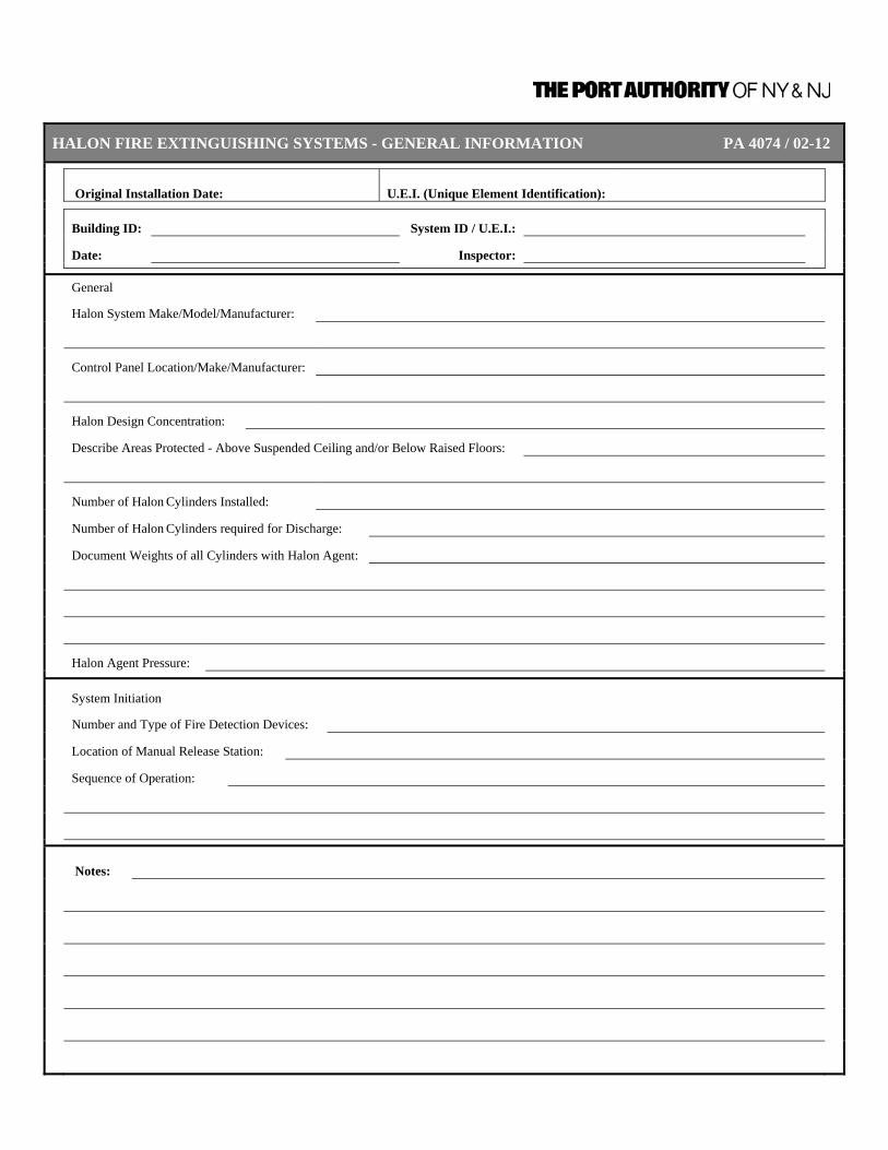
HALON FIRE EXTINGUISHING SYSTEMS - GENERAL INFORMATION PA 4074 / 02-12
Original Installation Date: U.E.I. (Unique Element Identification):
Building ID: System ID / U.E.I.:
Date: Inspector:
General
Halon System Make/Model/Manufacturer:
Control Panel Location/Make/Manufacturer:
Halon Design Concentration:
Describe Areas Protected - Above Suspended Ceiling and/or Below Raised Floors:
Number of Halon Cylinders Installed:
Number of Halon Cylinders required for Discharge:
Document Weights of all Cylinders with Halon Agent:
Halon Agent Pressure:
System Initiation
Number and Type of Fire Detection Devices:
Location of Manual Release Station:
Sequence of Operation:
Notes:
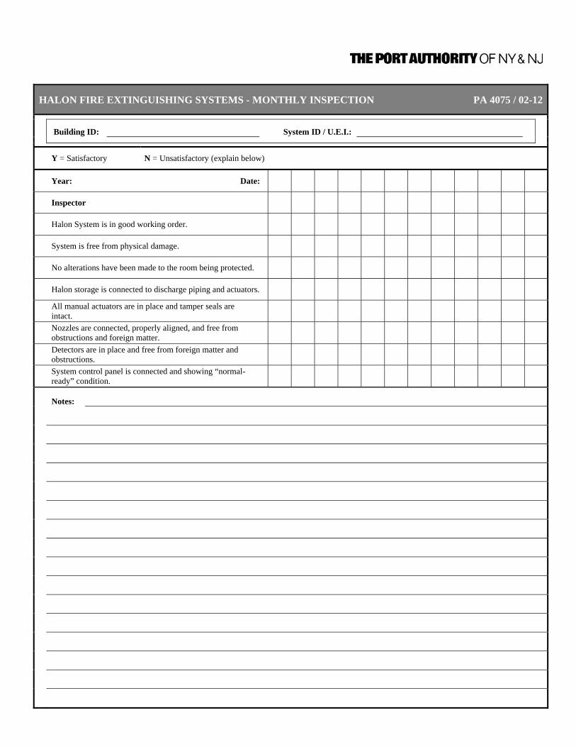
HALON FIRE EXTINGUISHING SYSTEMS - MONTHLY INSPECTION PA 4075 / 02-12
Building ID: System ID / U.E.I.:
Y = Satisfactory N = Unsatisfactory (explain below)
Year: Date:
Inspector
Halon System is in good working order.
System is free from physical damage.
No alterations have been made to the room being protected.
Halon storage is connected to discharge piping and actuators.
All manual actuators are in place and tamper seals are intact.
Nozzles are connected, properly aligned, and free from obstructions and foreign matter.
Detectors are in place and free from foreign matter and obstructions.
System control panel is connected and showing “normal-ready” condition.
Notes:

HALON FIRE EXTINGUISHING SYSTEMS - SEMI-ANNUAL INSPECTION AND TEST PA 4076 / 02-12
Building ID: System ID / U.E.I.:
Y = Satisfactory N = Unsatisfactory (explain below) N/A = Not applicable
Note: Test of system shall be done with automatic actuation controls from agent containers removed.
Year: Date
Inspector
Halon containers are free from physical damage.
Container pressure: (Pressure loss greater than 10% requires container refill or replacement.)
Container weight: (Weight loss greater than 5% requires container refill or replacement.)
Container pressure and weight are recorded on tag attached to container.
Test all detectors for proper alarm, supervision, and trouble functions.
Test detection system to operate the necessary circuit(s) to simulate agent release.
Operate all manual devices to simulate agent release.
Examine all containers for evidence of corrosion or mechanical damage.
Check container bracketing and supports to determine that their condition is satisfactory.
Examine piping for any evidence of corrosion.
Examine pipe hangers and straps to see that the piping is securely supported.
Check nozzles for proper position and alignment and determine that the orifices are clear and unobstructed.
Check nozzle seals, if applicable, for signs of deterioration.
Examine protected enclosure to determine if penetrations or other changes have occurred that could adversely affect halon leakage.
Notes:

HALON FIRE EXTINGUISHING SYSTEMS - ANNUAL INSPECTION AND TEST PA 4077 / 02-12
Building ID: System ID / U.E.I.:
Y = Satisfactory N = Unsatisfactory (explain below)
Year: Date:
Inspector
Examine all system hoses.
Operate all auxiliary and supplementary components such as switches, door and window releases, interconnected valves, damper releases, air handling equipment shutdown, and supplementary alarms to ensure that they are in proper operating condition.
Notes:
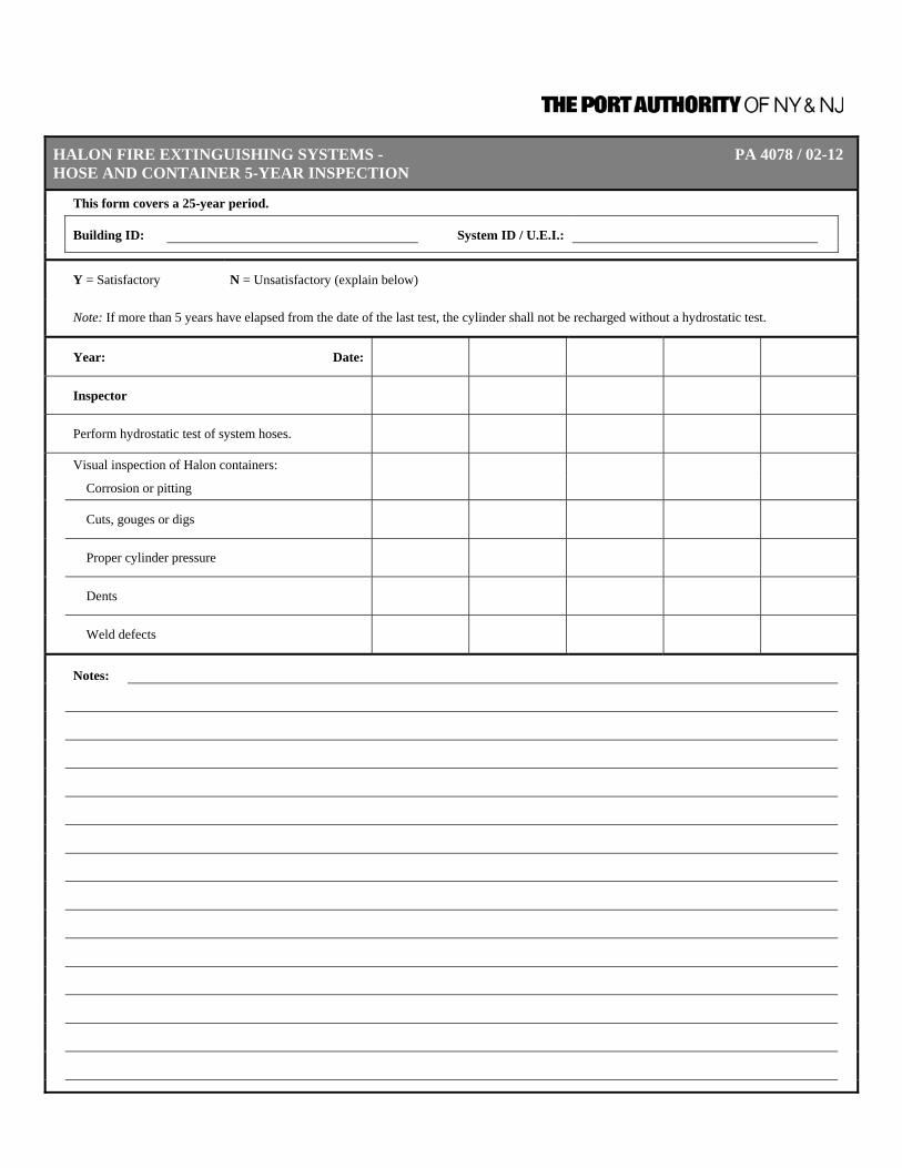
HALON FIRE EXTINGUISHING SYSTEMS - PA 4078 / 02-12 HOSE AND CONTAINER 5-YEAR INSPECTION
This form covers a 25-year period.
Building ID: System ID / U.E.I.:
Y = Satisfactory N = Unsatisfactory (explain below)
Note: If more than 5 years have elapsed from the date of the last test, the cylinder shall not be recharged without a hydrostatic test.
Year: Date:
Inspector
Perform hydrostatic test of system hoses.
Visual inspection of Halon containers:
Corrosion or pitting
Cuts, gouges or digs
Proper cylinder pressure
Dents
Weld defects
Notes:

Inspection, Testing, and Maintenance Requirements for Fire Protection and Life Safety Systems
CHAPTER 9 – DRY AND WET CHEMICAL FIRE EXTINGUISHING SYSTEMS 9/30/2011 | Page 9-1
CHAPTER 9 – DRY AND WET CHEMICAL FIRE
EXTINGUISHING SYSTEMS
DEFINITIONS Automatic Operation. Operation without human intervention. This operation
includes, but is not limited to, heat, rate of heat rise, smoke, or pressure change. [25:3.3]
Branch Duct. The duct work that contains the exhaust air from a single
hood or hazard area. Caking. A phenomenon that occurs when moisture chemically reacts
with a dry chemical fire-extinguishing agent. This reaction results in materials that, being hydrated by moisture, stick together to form a large agglomerate, or what is more commonly referred to as lumps.
Clearance. The air distance between extinguishing system equipment,
including piping and nozzles, and unenclosed or uninsulated live electrical components not at ground potential.
Common Duct. The duct work containing the exhaust air from two or more
branch ducts. Discharge Nozzle. Device from which the dry chemical is discharged to provide
for suppression of a fire in the designated hazard. Dry Chemical. A powder composed of very small particles, usually sodium
bicarbonate-, potassium bicarbonate-, or ammonium phosphate-based with added particulate material supplemented by special treatment to provide resistance to packing, resistance to moisture absorption (caking), and the proper flow capabilities.
Dry Chemical System. A means of applying dry chemical that can be automatically
or manually activated to discharge through a distribution system onto or into the protected hazard. The system includes auxiliary equipment.
Engineered System. Those requiring individual calculation and design to
determine the flow rates, nozzle pressures, pipe size, area or volume protected by each nozzle, quantities of dry chemical, number and types of nozzles, and their placement in a specific system.
Expellant Gas. The medium used to discharge dry chemical from its
container.

Inspection, Testing, and Maintenance Requirements for Fire Protection and Life Safety Systems
CHAPTER 9 – DRY AND WET CHEMICAL FIRE EXTINGUISHING SYSTEMS 9/30/2011 | Page 9-2
Hand Hose Line System. A hose and nozzle assembly connected by fixed piping or connected directly to a supply of extinguishing agent. [122:1.4]
Indicator. A mechanical or electrical device that shows when an
extinguishing system or a critical component of it is ready to operate, or if it has already operated.
Local Application System. A supply of dry chemical permanently connected to fixed
piping with nozzles arranged to discharge directly onto the fire.
Lumps. Agglomerations of dry chemical that do not crumble into
particles when dropped from a height of 4 in. (101 mm) onto a hard surface.
Manual Operation. Operation of a system or its components through human
action. Manufacturer’s Listed Installation and The pamphlet referenced as part of the listing of the wet or
dry Maintenance Manual. chemical extinguishing system. Multipurpose Dry Chemical. Ammonium phosphatebased extinguishing agent that is
effective on fires involving both ordinary combustibles, such as wood or paper, and fires involving flammable liquids.
Owner’s Manual. A pamphlet containing the manufacturer’s recommendations
for the proper inspection and operation of the extinguishing system.
Operating Devices. Mechanical, electrical, or pneumatic devices involved in the
operation of a system whether “actuating devices” initiating operation (e.g., automatic detection devices or systems and manual actuation devices, such as manual pulls or strike buttons) or “operated devices” responding to the actuation (e.g., release mechanisms, shutoff devices, alarms, and auxiliary equipment).
Pre-Engineered Systems. Those having predetermined flow rates, nozzle pressures,
and quantities of extinguishing agent. These systems have the specific pipe size, maximum and minimum pipe lengths, flexible hose specifications, number of fittings, and number and types of nozzles prescribed by a testing laboratory. The maximum and minimum pipe lengths and the number of fittings shall be permitted to be expressed in equivalent feet of pipe. The hazards protected by these systems are specifically limited as to type and size by a testing laboratory, based on actual fire tests. Limitations on hazards that are permitted to be protected by these systems and piping and nozzle configurations are contained in the

Inspection, Testing, and Maintenance Requirements for Fire Protection and Life Safety Systems
CHAPTER 9 – DRY AND WET CHEMICAL FIRE EXTINGUISHING SYSTEMS 9/30/2011 | Page 9-3
manufacturer’s listed installation and maintenance manual, which is part of the listing of the system.
Selector Valve. Adevice used to direct dry chemical to the hazard being
protected. Shutoff Devices. Devices that operate simultaneously with the extinguishing
system to shut off fuel and power to appliances protected by the system and other appliances required to be shut off upon operation of the system.
Total Flooding System. A supply of dry chemical permanently connected to fixed
piping and nozzles that are arranged to discharge dry chemical into an enclosure surrounding the hazard.
Wet Chemical. Normally an aqueous solution of organic or inorganic salts or
a combination thereof that forms an extinguishing agent.

Inspection, Testing, and Maintenance Requirements for Fire Protection and Life Safety Systems
CHAPTER 9 – DRY AND WET CHEMICAL FIRE EXTINGUISHING SYSTEMS 9/30/2011 | Page 9-4
A. DRY CHEMICAL SYSTEMS 1. Existing Dry Chemical
Systems General Information
Update Annually Form PA 4080
Review General Information Form for all Dry Chemical Systems, update as required.
2. New or Altered Dry Chemical
Systems – General Information Update As Required Form PA 4080
Complete General Information Form for new Dry Chemical System or update General Information Form for Dry Chemical System that has been altered to include repairs and/or modifications to components.
3. Dry Chemical Systems Inspection Monthly Form PA 4081
11.2.1 On a monthly basis, inspection shall be conducted in accordance with the manufacturer’s listed installation and maintenance manual or owner’s manual.
11.2.1.1 As a minimum, this “quick check” or inspection shall include verification of the
following:
1) The extinguishing system is in its proper location. 2) The manual actuators are unobstructed. 3) The tamper indicators and seals are intact. 4) The maintenance tag or certificate is in place. 5) The system shows no physical damage or condition that might
prevent operation. 6) The pressure gauge(s), if provided, is in operable range. 7) The nozzle blowoff caps, where provided, are intact and
undamaged. 8) Neither the protected equipment nor the hazard has been replaced,
modified, or relocated.
11.2.2 If any deficiencies are found, appropriate corrective action shall be taken immediately.
11.2.3 Personnel making inspections shall keep records for those extinguishing
systems that were found to require corrective actions.
11.2.4 At least monthly, the date the inspection is performed and the initials of the person performing the inspection shall be recorded. The records shall be retained until the next semi-annual maintenance.

Inspection, Testing, and Maintenance Requirements for Fire Protection and Life Safety Systems
CHAPTER 9 – DRY AND WET CHEMICAL FIRE EXTINGUISHING SYSTEMS 9/30/2011 | Page 9-5
4. Dry Chemical Systems Testing Semi-Annual Form PA 4083
11.3.1.4 All dry chemical systems shall be tested, which shall include the operation of the detection system, signals, and releasing devices, including manual stations and other associated equipment.
A.11.3.1.4 A discharge of the dry chemical normally is not part of this test.
5. Dry Chemical Systems Maintenance Semi-Annual Form PA 4082
11.3.1 At least semiannually, maintenance shall be conducted in accordance with the manufacturer’s listed installation and maintenance manual.
11.3.1.1 As a minimum, such maintenance shall include the following:
1) A check to see that the hazard has not changed 2) An examination of all detectors, expellant gas container(s), agent
container(s), releasing devices, piping, hose assemblies, nozzles, signals, and all auxiliary equipment
3) Verification that the agent distribution piping is not obstructed. A.11.3.1.1(3) The following methods can be used for verifying
that the piping is not obstructed: a) Disassembly of all piping b) Purging of piping with nitrogen or dry air c) Conducting a full or partial discharge test d) Utilizing methods recommended by the manufacturer
4) Examination of the dry chemical (If there is evidence of caking, the dry chemical shall be discarded and the system shall be recharged in accordance with the manufacturer’s instructions.)
11.3.1.3 Where semiannual maintenance of any dry chemical containers or system
components reveals conditions such as, but not limited to, corrosion or pitting in excess of the manufacturer’s limits, structural damage or fire damage, or repairs by soldering, welding, or brazing, the affected part(s) shall be replaced or hydrostatically tested in accordance with the recommendations of the manufacturer or the listing agency.
11.3.1.5 Where the maintenance of the system(s) reveals defective parts that could
cause an impairment or failure of proper operation of the system(s), the affected parts shall be replaced or repaired in accordance with the manufacturer’s recommendations.
11.3.1.6 The maintenance report, including any recommendations, shall be filed with
the owner or with the designated party responsible for the system.
11.3.1.7 Each dry chemical system shall have a tag or label indicating the month and year the maintenance is performed and identifying the person performing the service. Only the current tag or label shall remain in place.
A.11.3.1.7 Under special circumstance or when local requirements are in effect,
additional information can be desirable or required.

Inspection, Testing, and Maintenance Requirements for Fire Protection and Life Safety Systems
CHAPTER 9 – DRY AND WET CHEMICAL FIRE EXTINGUISHING SYSTEMS 9/30/2011 | Page 9-6
6. Dry Chemical Maintenance 6 Years Form PA 4082
11.3.1.2 Dry chemical in stored pressure systems shall not require semiannual examination but shall be examined at least every 6 years as identified in 5 above [11.3.1.1 4) and 11.3.1.3].
7. Fixed Temperature – Sensing
Elements Maintenance Annually Form PA 4084
11.3.2 Fixed temperature-sensing elements of the fusible metal alloy type shall be
replaced at least annually from the date of installation.
11.3.2.1 Upon removal the links shall be destroyed.
11.3.2.2 The year of manufacture and the date of installation of the fixed temperature-sensing element shall be marked on the system inspection tag.
11.3.2.3 The tag shall be signed or initialed by the installer.
11.3.3 Fixed temperature-sensing elements other than the fusible metal alloy type
shall be permitted to remain continuously in service, provided they are inspected and cleaned or replaced if necessary in accordance with the manufacturer’s instructions every 12 months or more frequently to ensure proper operation of the system.
8. Recharging Maintenance As Needed Form PA 4084
11.4.1 All extinguishing systems shall be recharged after use or as indicated by an inspection or a maintenance check.
11.4.2 Systems shall be recharged in accordance with the manufacturer’s listed
installation and maintenance manual. 9. Hydrostatic Testing Testing 12 Years Form PA 4085
11.5 Hydrostatic Testing. Hydrostatic testing shall be performed by persons trained in pressure-testing procedures and safeguards and having available suitable testing equipment, facilities, and an appropriate service manual(s).
11.5.1 The following parts of dry chemical extinguishing systems shall be subjected
to a hydrostatic pressure test at intervals not exceeding 12 years: 1) Dry chemical containers 2) Auxiliary pressure containers 3) Hose assemblies

Inspection, Testing, and Maintenance Requirements for Fire Protection and Life Safety Systems
CHAPTER 9 – DRY AND WET CHEMICAL FIRE EXTINGUISHING SYSTEMS 9/30/2011 | Page 9-7
Exception No. 1: Dry chemical containers that are part of extinguishing systems having an agent capacity exceeding 150 lb. (68 kg).
Exception No. 2: Auxiliary pressure containers not exceeding 2 in. (0.05m) outside diameter and less than 2 ft. (0.6m) in length.
Exception No. 3: Auxiliary pressure containers bearing the DOT “3E” marking.
11.5.2 Dry chemical containers, auxiliary pressure containers, and hose assemblies
shall be subjected to a hydrostatic test pressure equal to the marked factory test pressure or the test pressure specified in the manufacturer’s listed installation and maintenance manual.
11.5.2.1 No leakage, rupture, or movement of hose couplings shall be permitted.
11.5.2.2 The test procedures shall be in accordance with the manufacturer’s detailed
written hydrostatic test instructions.
11.5.2.3 Prior to being refilled or transported, in accordance with DOT or TC requirements, containers bearing DOT or TC markings shall be retested or replaced in accordance with the appropriate DOT or TC requirements.
11.5.3 Dry chemical agent removed from the containers prior to hydrostatic testing
shall be discarded.
11.5.4 Care shall be taken to ensure that all tested equipment is thoroughly dried prior to reuse.
11.5.5 To protect the hazard during hydrostatic testing, if there is no connected
reserve, alternate protection acceptable to the authority having jurisdiction shall be provided.
A.11.5.2.3 DOT or TC marked containers installed in a system that is not under the
jurisdiction of DOT or TC are not required to follow DOT or TC requirements as long as they remain in operation.
B. Wet Chemical Systems 1. Existing Wet Chemical
Systems – General Information Update Annually Form PA 4086
Review General Information Form for all Wet Chemical Systems, update as required.

Inspection, Testing, and Maintenance Requirements for Fire Protection and Life Safety Systems
CHAPTER 9 – DRY AND WET CHEMICAL FIRE EXTINGUISHING SYSTEMS 9/30/2011 | Page 9-8
2. New or Altered Wet Chemical
Systems – General Information Update As Required Form PA 4086
Complete General Information Form for new Wet Chemical System or update General Information Form for Wet Chemical System that has been altered to include repairs and/or modifications to components.
3. Wet Chemical System Inspection Monthly Form PA 4081
7.2.1 Inspection shall be conducted on a monthly basis in accordance with the manufacturer’s listed installation and maintenance manual or the owner’s manual.
7.2.2 Inspections shall include verification of the following:
1) The extinguishing system is in its proper location. 2) The manual actuators are unobstructed. 3) The tamper indicators and seals are intact. 4) The maintenance tag or certificate is in place. 5) No obvious physical damage or condition exists that might prevent
operation. 6) The pressure gauge(s), if provided, is in operable range. 7) The nozzle blowoff caps are intact and undamaged. 8) The hood, duct, and protected cooking appliances have not been
replaced, modified, or relocated.
7.2.3 If any deficiencies are found, appropriate corrective action shall be taken immediately.
7.2.4 Personnel making inspections shall keep records for those extinguishing
systems that were found to require corrective actions.
7.2.5 At least monthly, the date the inspection is performed and the initials of the person performing the inspection shall be recorded.
4. Wet Chemical System Testing Semi-Annual Form PA 4083
7.3.2.3 All wet chemical systems shall be tested, which shall include the operation of the detection system signals and releasing devices, including manual stations and other associated equipment.
A.7.3.2.3 A discharge of the wet chemical normally is not part of this test.

Inspection, Testing, and Maintenance Requirements for Fire Protection and Life Safety Systems
CHAPTER 9 – DRY AND WET CHEMICAL FIRE EXTINGUISHING SYSTEMS 9/30/2011 | Page 9-9
5. Wet Chemical System Maintenance Semi-Annual Form PA 4082
7.3.1 A trained person who has undergone the instructions necessary to perform the maintenance and recharge service reliably and has the applicable manufacturer’s listed installation and maintenance manual land service bulletins shall service the wet chemical fire-extinguishing system 6 months apart as outlined in 7.3.2.
7.3.2 At least semiannually, maintenance shall be conducted in accordance with
the manufacturer’s listed installation and maintenance manual.
7.3.2.1 Maintenance shall include the following: 1) A check to see that the hazard has not changed. 2) An examination of all detectors, the expellant gas container(s), the
agent container(s), releasing devices, piping, hose assemblies, nozzles, signals, all auxiliary equipment, and the liquid level of all non-pressurized wet chemical containers.
3) Verification that the agent distribution piping is not obstructed.
A.7.3.2.1(3) The following methods can be used to verify that piping is not obstructed: 1) Disassembly of all piping 2) Conducting a full or partial discharge test 3) Utilizing other methods recommended by the manufacturer
7.3.2.2 Where semiannual maintenance of any wet chemical containers or system
components reveals conditions such as, but not limited to, corrosion or pitting in excess of the manufacturer’s limits; structural damage or fire damage; or repairs by soldering, welding, or brazing; the affected part(s) shall be replaced or hydrostatically tested in accordance with the recommendations of the manufacturer or the listing agency.
7.3.2.4 Where the maintenance of the system(s) reveals defective parts that could
cause an impairment or failure of proper operation of the system(s), the affected parts shall be replaced or repaired in accordance with the manufacturer’s recommendations.
7.3.2.5 The maintenance report, with recommendations, if any, shall be filed with the
owner or with the designated party responsible for the system.
7.3.2.6 Each wet chemical system shall have a tag or label securely attached, indicating the month and year the maintenance is performed and identifying the person performing the service. Only the current tag or label shall remain in place.
7.3.3 Fixed temperature-sensing elements of the fusible metal alloy type shall be
replaced at least annually from the date of installation. They shall be destroyed when removed.
7.3.3.1 The year of manufacture and the date of installation of the fixed temperature-
sensing element shall be marked on the system inspection tag. The tag shall be signed or initialed by the installer.

Inspection, Testing, and Maintenance Requirements for Fire Protection and Life Safety Systems
CHAPTER 9 – DRY AND WET CHEMICAL FIRE EXTINGUISHING SYSTEMS 9/30/2011 | Page 9-10
6. Fixed Temperature – Sensing
Elements Maintenance Annually Form PA 4084
7.3.4 Fixed temperature-sensing elements other than the fusible metal alloy type
shall be permitted to remain continuously in service, provided they are inspected and cleaned or replaced, if necessary, in accordance with the manufacturer’s instructions every 12 months or more frequently to ensure proper operation of the system.
7. Recharging Maintenance As Needed Form PA 4084
7.4.1 All extinguishing systems shall be recharged after use or as indicated by an inspection or maintenance procedure.
7.4.2 Systems shall be recharged in accordance with the manufacturer’s listed
installation and maintenance manual. 8. Hydrostatic Testing Testing 12 Years Form PA 4085
7.5.1 The following parts of wet chemical extinguishing systems shall be subjected to a hydrostatic pressure test at intervals not exceeding 12 years: 1) Wet chemical containers 2) Auxiliary pressure containers 3) Hose assemblies
Exception No. 1: Auxiliary pressure containers not exceeding 2-in. (0.05-m) outside diameter and less than 2 ft. (0.6m) in length.
Exception No. 2: Auxiliary pressure containers bearing the DOT “3E” marking.
7.5.2 Wet chemical containers, auxiliary pressure containers, and hose assemblies
shall be subjected to a hydrostatic test pressure equal to the marked factory test pressure or the test pressure specified by the manufacturer.
7.5.2.1 No leakage, rupture, or movement of hose couplings shall be permitted.
7.5.2.2 The test procedures shall be in accordance with the manufacturer’s detailed
written hydrostatic test instructions.
7.5.2.3 Prior to being refilled or transported, in accordance with DOT or TC requirements, containers bearing DOT or TC markings shall be retested or replaced in accordance with the appropriate DOT or TC requirements.
7.5.3 Wet chemical agent removed from the containers prior to hydrostatic testing
shall be discarded.
Inspection, Testing, and Maintenance Requirements for Fire Protection and Life Safety Systems
CHAPTER 9 – DRY AND WET CHEMICAL FIRE EXTINGUISHING SYSTEMS 9/30/2011 | Page 9-11
7.5.4 To protect the hazard during hydrostatic testing, if there is no connected reserve, alternate protection acceptable to the authority having jurisdiction shall be provided.

DRY AND WET CHEMICAL FIRE EXTINGUISHING SYSTEMS - PA 4080 / 02-12 GENERAL INFORMATION (FIXED DRY CHEMICAL)
Original Installation Date: U.E.I. (Unique Element Identification) :
Building ID: System ID / U.E.I.:
Date: Inspector:
Manufacturer:
Date Installed:
Service Contractor:
Type of extinguishing agent
Dry chemical cylinder Normal pressure psi (bar)
Manufacturer's minimum pressure psi (bar)
Normal weight lbs (kg)
Manufacturer's minimum weight lbs (kg)
Equipment Protected Deep-fat fryer(s) Upright broiler(s) Fuel Island
Grill(s) Griddle(s) Other
Charbroiler(s) Range top(s)
Expellant gas cartridge - any provided? Yes No
If yes, normal weight (if carbon dioxide) lbs (kg)
normal pressure (if nitrogen) psi (bar)
Connected to main base building fire alarm system? Yes No
Automatic shutdown of cooking equipment? Yes No
If yes, Gas Electric
Notes:
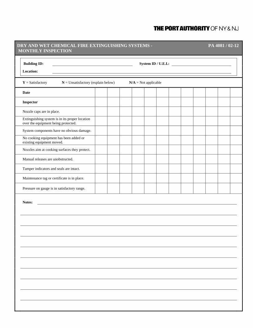
DRY AND WET CHEMICAL FIRE EXTINGUISHING SYSTEMS - PA 4081 / 02-12 MONTHLY INSPECTION
Building ID: System ID / U.E.I.:
Location:
Y = Satisfactory N = Unsatisfactory (explain below) N/A = Not applicable
Date
Inspector
Nozzle caps are in place.
Extinguishing system is in its proper location over the equipment being protected.
System components have no obvious damage.
No cooking equipment has been added or existing equipment moved.
Nozzles aim at cooking surfaces they protect.
Manual releases are unobstructed.
Tamper indicators and seals are intact.
Maintenance tag or certificate is in place.
Pressure on gauge is in satisfactory range.
Notes:

DRY AND WET CHEMICAL FIRE EXTINGUISHING SYSTEMS - PA 4082 / 02-12 SEMI-ANNUAL OR 6-YEAR MAINTENANCE
Building ID: System ID / U.E.I.:
Location:
Y = Satisfactory N = Unsatisfactory (explain below) N/A = Not applicable Note: Dry chemical in stored pressure system shall only need to be examined every 6 years.
Date
Inspector
Record pressure (psi):
Expellant gas cartridge: Pressure of nitrogen in psi (bar)
Weight of carbon dioxide in lb (kg)
Examine dry chemical agent for lumping or caking in cartridge-operated-type systems.
Check to assure that hazard has not changed.
Examine detectors for damage or changes.
Examine expellant gas containers for damage or changes.
Examine agent containers for damage or changes.
Examine manual releases for damage or changes.
Examine piping for damage, changes or obstructions.
Examine hose assemblies for damage or changes.
Examine discharge nozzles for damage or changes.
Notes:

DRY AND WET CHEMICAL FIRE EXTINGUISHING SYSTEMS - PA 4083 / 02-12SEMI-ANNUAL TEST
Building ID: System ID / U.E.I.:
Date: Inspector:
Location:
Y = Satisfactory N = Unsatisfactory (explain below)
Actuating Test Manual Release
Fusible Link
Alarm connection to main base building fire alarm system.
Connection to shut off power to cooking equipment.
Connection to shut down make-up air to exhaust hood.
Grease exhaust fan. Indicate if fan continues to run (C) or shuts down (S).
Notes:

DRY AND WET CHEMICAL FIRE EXTINGUISHING SYSTEMS - PA 4084 / 02-12 ANNUAL MAINTENANCE
Building ID: System ID / U.E.I.:
Date: Inspector:
Location:
Y = Yes N = No
Replace fixed temperature elements
Destroy replaced links
Fixed temperature-sensing elements other than the fusible metal alloy may remain in service if inspected and cleaned. Indicate Yes if inspected and cleaned, or No if replaced.
Recharging Document recharge of extinguishing systems either after use, as indicated by inspection, by maintenance check, or as per manufacturer’s instructions. Recharging is not required annually but as needed.
Notes:

DRY AND WET CHEMICAL FIRE EXTINGUISHING SYSTEMS - PA 4085 / 02-12 12-YEAR HYDROSTATIC TEST
Building ID: System ID / U.E.I.:
Date: Inspector:
Location:
Y = Satisfactory N = Unsatisfactory (explain below)
Hydrostatic test performed on: Agent containers Auxiliary pressure containers Hose assemblies
Notes:

DRY AND WET CHEMICAL FIRE EXTINGUISHING SYSTEMS - PA 4086 / 02-12 GENERAL INFORMATION (FIXED WET CHEMICAL)
Building ID: System ID / U.E.I.:
Date: Inspector:
Location:
Manufacturer: Date Installed: Service Contractor:
Type of extinguishing agent:
Wet chemical cylinder Normal pressure psi (bar) Manufacturer's minimum pressure psi (bar) Normal weight lbs (kg) Manufacturer's minimum weight lbs (kg)
Equipment Protected Deep-fat fryer(s) Upright broiler(s) Other
Grill(s) Griddle(s)
Charbroiler(s) Range top(s)
Expellant gas cartridge - any provided? Yes No
If yes, normal weight (if carbon dioxide) lbs (kg)
normal pressure (if nitrogen) psi (bar)
Connected to main base building fire alarm system? Yes No
Automatic shutdown of cooking equipment? Yes No
If yes, Gas Electric
Notes:

Inspection, Testing, and Maintenance Requirements for Fire Protection and Life Safety Systems
CHAPTER 10 – CLEAN AGENT FIRE EXTINGUISHING SYSTEMS 9/30/2011 | Page 10-1
CHAPTER 10 – CLEAN AGENT FIRE
EXTINGUISHING SYSTEMS
DEFINITIONS Clean Agent. Electrically nonconducting, volatile, or gaseous fire
extinguishant that does not leave a residue upon evaporation. The word agent as used in this document means clean agent unless otherwise indicated.
Clearance. The air distance between extinguishing system equipment,
including piping and nozzles, and unenclosed or uninsulated live electrical components not at ground potential.
Design Factor (DF). A fraction of the agent minimum design quantity (MDQ)
added thereto deemed appropriate due to a specific feature of the protection application or design of the suppression system.
Electric Control Equipment. The control equipment shall supervise the actuating devices
and associated wiring and, as required, cause actuation. The control equipment shall be specifically listed for the number and type of actuating devices utilized, and their compatibility shall have been listed.
Engineered System. Asystem requiring individual calculation and design to
determine the flow rates, nozzle pressures, pipe size, area or volume protected by each nozzle, quantity of agent, and the number and types of nozzles and their placement in a specific system.
Halocarbon Agent. An agent that contains as primary components one or more
organic compounds containing one or more of the elements fluorine, chlorine, bromine, or iodine.
Inert Gas Agent. An agent that contains as primary components one or more
of the gases helium, neon, argon, or nitrogen. Inert gas agents that are blends of gases can also contain carbon dioxide as a secondary component.
Minimum Design Quantity (MDQ). The quantity of agent required to achieve the minimum
design concentration as calculated using the method in 5.5.1 or 5.5.2, as appropriate.
Normally Occupied Area. One that is intended for occupancy.

Inspection, Testing, and Maintenance Requirements for Fire Protection and Life Safety Systems
CHAPTER 10 – CLEAN AGENT FIRE EXTINGUISHING SYSTEMS 9/30/2011 | Page 10-2
Pneumatic Control Equipment. Where pneumatic control equipment is used, the lines shall be protected against crimping and mechanical damage. Where installations could be exposed to conditions that could lead to loss of integrity of the pneumatic lines, special precautions shall be taken to ensure that no loss of integrity will occur. The control equipment shall be specifically listed for the number and type of actuating devices utilized, and their compatibility shall have been listed.
Pre-Engineered System. A system having predetermined flow rates, nozzle
pressures, and quantities of agent. These systems have the specific pipe size, maximum and minimum pipe lengths, flexible hose specifications, number of fittings, and number and types of nozzles prescribed by a testing laboratory. The hazards protected by these systems are specifically limited as to type and size by a testing laboratory based upon actual fire tests. Limitations on hazards that can be protected by these systems are contained in the manufacturer’s installation manual, which is referenced as part of the listing.
Primary Agent Supply. The amount of agent in the system primary agent supply
shall be at least sufficient for the largest single hazard protected or group of hazards to be protected simultaneously.
Reserve Agent Supply. Where required, a reserve agent supply shall consist of as
many multiples of the primary agent supply as the authority having jurisdiction considers necessary.
Safety Factor (SF). A multiplier of the agent flame extinguishing or inerting
concentration to determine the agent minimum design concentration.
Storage Containers. Agent shall be stored in containers designed to hold that
specific agent at ambient temperatures. Containers shall be charged to a fill density or superpressurization level within the range specified in the manufacturer’s listed manual.
Superpressurization. The addition of gas to a fire extinguishing agent container to
achieve a specified pressure therein. Total Flooding. The act and manner of discharging an agent for the purpose
of achieving a specified minimum agent concentration throughout a hazard volume.
Total Flooding System. A system consisting of an agent supply and distribution
network designed to achieve a total flooding condition in a hazard volume.
Uninterrupted Protection. Where uninterrupted protection is required, both the primary
and the reserve agent supplies shall be permanently connected to the distribution piping and arranged for easy changeover.

Inspection, Testing, and Maintenance Requirements for Fire Protection and Life Safety Systems
CHAPTER 10 – CLEAN AGENT FIRE EXTINGUISHING SYSTEMS 9/30/2011 | Page 10-3
1. Existing Clean Agent
Systems – General Information Update Annually Form PA 4091
Review General Information Form for all Clean Agent Fire Extinguishing Systems, update as required. Confirm that the as-built instruction, maintenance manual, and a full set of drawings is provided as required: 5.1.2.4 An as-built instruction and maintenance manual that includes a full sequence
of operations and a full set of drawings and calculations shall be maintained on site.
2. New or Altered Clean Agent
Systems – General Information Update As Required Form PA 4091
Complete General Information Form for new Clean Agent Fire Extinguishing System or update General Information Form for Clean Agent Fire Extinguishing System that has been altered to include repairs and/or modifications to components. Confirm that the as-built instruction, maintenance manual, and full set of drawings is provided as required: 5.1.2.4 An as-built instruction and maintenance manual that includes a full sequence
of operations and a full set of drawings and calculations shall be maintained on site.
3. Clean Agent System Inspection Monthly Form PA 4092
904.10.1 At least once a month, an inspection shall be conducted by a trained and
knowledgeable person as assess whether the system is in good working order.
4. Clean Agent System Inspection,
Testing Annually Form PA 4094
6.1.1 At least annually, all systems shall be thoroughly inspected and tested for
proper operation by competent personnel. Discharge tests are not required.
6.1.2 The inspection report with recommendations shall be filed with the owner.

Inspection, Testing, and Maintenance Requirements for Fire Protection and Life Safety Systems
CHAPTER 10 – CLEAN AGENT FIRE EXTINGUISHING SYSTEMS 9/30/2011 | Page 10-4
5. Clean Agent System Inspection,
Testing Semi-Annually
Form PA 4093
6.1.3 At least semiannually, the agent quantity and pressure of refillable containers
shall be checked.
6.1.3.1 For halocarbon clean agents, if a container shows a loss in agent quantity of more than 5 percent or a loss in pressure (adjusted for temperature) of more than 10 percent, it shall be refilled or replaced.
6.1.3.2 For inert gas clean agents that are not liquefied, pressure is an indication of
agent quantity. If an inert gas clean agent container shows a loss in pressure (adjusted for temperature) of more than 5 percent, it shall be refilled or replaced. Where container pressure gauges are used for this purpose, they shall be compared to a separate calibrated device at least annually.
6.1.3.3 Where the amount of agent in the container is determined by special
measuring devices, these devices shall be listed.
6.1.4 All halocarbon clean agents removed from refillable containers during service or maintenance procedures shall be collected and recycled or disposed of in an environmentally sound manner and in accordance with existing laws and regulations.
6.1.5 Factory-charged, non-refillable containers that do not have a means of
pressure indication shall have the agent quantity checked at least semiannually. If a container shows a loss in agent quantity of more than 5 percent, it shall be replaced. All factory-charged, non-refillable containers removed from useful service shall be returned for recycling of the agent or disposed of in and environmentally sound manner and in accordance with existing laws and regulations.
6.1.6 For halocarbon clean agents, the date of inspection, gross weight of cylinder
plus agent or net weight of agent, type of agent, person performing the inspection, and, where applicable, the pressure at a recorded temperature shall be recorded on a tag attached to the container. For inert gas clean agents, the date of inspection, type of agent, person performing the inspection, and the pressure at a recorded temperature shall be recorded on the tag attached to the container.

Inspection, Testing, and Maintenance Requirements for Fire Protection and Life Safety Systems
CHAPTER 10 – CLEAN AGENT FIRE EXTINGUISHING SYSTEMS 9/30/2011 | Page 10-5
6. Container Inspection,
Testing 5 Years Form PA 4095
6.2.2 Cylinders continuously in service without discharging shall be given a
complete external visual inspection every 5 years or more frequently if required. The visual inspection shall be in accordance with Section 3 of CGA C-6, Standard for Visual Inspection of Steel Compressed Gas Cylinders, except that the cylinders need not be emptied or stamped while under pressure. Inspections shall be made only by competent personnel, and the results recorded on both of the following: 1) A record tag permanently attached to each cylinder 2) A suitable inspection report
The following is the visual inspection defined by the Compressed Gas Association Pamphlet C-6, Section 3:
3.1 Corrosion or pitting – Loss of wall thickness in a cylinder by corrosive media.
3.1.1 Crevice corrosion – Corrosion that occurs in the area of the intersection of
the footring or headring with the cylinder.
3.1.2 Isolated pitting – Isolated pits of small diameter that do not effectively weaken a cylinder.
3.1.3 Line corrosion – Corrosion that results in a continuous patter or when pits are
connected to others in a narrow band or line. This condition is more serious than isolated pitting.
3.1.4 General corrosion – Corrosion that covers considerable surface areas of the
cylinder.
3.2 Cuts, gouges, or digs – Deformations in a cylinder caused by contact with a sharp object so as to cut into or upset the metal of the cylinder, decreasing the wall thickness at that point.
3.3 Cylinder, high and low pressure – High pressure cylinders are those with a
marked service pressure of 900 psi (6210 kPa) or greater; low pressure cylinders are those with a marked service pressure less than 900 psi (6210 kPa).
3.4 Cylinder disposition – The following definitions apply to terms for the
disposition of cylinders failing visual inspection.
3.4.1 Condemned – Scrap, no longer fit for service.
3.4.2 Rejected – Not fit for service in present condition.
Note – Rejected cylinders may be requalified by either additional testing to verify adequacy of cylinder for continued service or by reheat treatment, repair, or rebuilding to correct the defect as specified in 49 CFR 180 Subpart C.

Inspection, Testing, and Maintenance Requirements for Fire Protection and Life Safety Systems
CHAPTER 10 – CLEAN AGENT FIRE EXTINGUISHING SYSTEMS 9/30/2011 | Page 10-6
3.5 Dents – Deformations in a cylinder caused by its coming in contact with a blunt object so the thickness of metal is not materially impaired.
3.6 Minimum allowable design thickness – Minimum design thickness required
by the specification under which the cylinder was manufactured.
3.7 Weld defects – Cracks or flaws in weld areas that reduce the structural strength of metal, which can cause separation when pressurized.
6.2.2.1 A completed copy of the inspection report shall be furnished to the owner of
the system or an authorized representative. These records shall be retained by the owner for the life of the system.
6.2.3 Where external visual inspection indicates that the container has been
damaged, additional strength tests shall be required. 7. Hose Inspection Annually Form PA 4094
6.3.1 General. All system hose shall be examined annually for damage. If visual
examination shows any deficiency, the hose shall be immediately replaced or tested as specified in 6.3.2 as identified in Number 8 below.
8. Hose Testing 5 Years Form PA 4095
6.3.2.1 All hose shall be tested every 5 years.
6.3.2.2 All hose shall be tested at 1 1⁄2 times the maximum container pressure at
130°F (54.4°C). The testing procedure shall be as follows: 1) The hose is removed from any attachment. 2) The hose assembly is then placed in a protective enclosure
designed to permit visual observation of the test. 3) The hose must be completely filled with water before testing. 4) Pressure then is applied at a rate-of-pressure rise to reach the test
pressure within a minimum of 1 minute. The test pressure is maintained for 1 full minute. Observations are then made to note nay distortion or leakage.
5) If the test pressure has not dropped or if the couplings have not moved, the pressure is released. The hose assembly is then considered to have passed the hydrostatic test if no permanent distortion has taken place.
6) Hose assembly passing the test must be completely dried internally. If heat is used for drying, the temperature must not exceed the manufacturer’s specifications.
7) Hose assemblies failing a hydrostatic test must be marked and destroyed and be replaced with new assemblies.
8) Each hose assembly passing the hydrostatic test is marked to show the date of test.

Inspection, Testing, and Maintenance Requirements for Fire Protection and Life Safety Systems
CHAPTER 10 – CLEAN AGENT FIRE EXTINGUISHING SYSTEMS 9/30/2011 | Page 10-7
9. Room Enclosure Inspection Annually Form PA 4094
6.4 Enclosure Inspection. Other than as identified in 6.4.1, the enclosure
protected by the clean agent shall be thoroughly inspected at least every 12 months to determine if penetrations or other changes have occurred that could adversely affect agent leakage or change volume of hazard, or both. Where the inspection indicated conditions that could result in the inability to maintain the clean agent concentration, the conditions shall be corrected. If uncertainty still exists, the enclosures shall be retested for integrity in accordance with 6.7.2.3.
6.7.2.3 Review Enclosure Integrity. All total flooding systems shall have the
enclosure examined and tested to locate and then effectively seal any significant air leaks that could result in a failure of the enclosure to hold the specified agent concentration level for the specified holding period. The currently preferred method is using a blower door fan unit and smoke pencil. Quantitative results shall be obtained and recorded to indicate that the specified agent concentration for the specified duration of protection is in compliance with Section 5.6, using an approved blower fan unit or other means as approved by the authority having jurisdiction.
6.4.1 An enclosure inspection shall not be required every 12 months if a
documented administrative control program exists that addresses barrier integrity.
6.5.3 Any penetrations made through the enclosure protected by the clean agent
shall be sealed immediately. The method of sealing shall restore the original fire resistance rating of the enclosure.

CLEAN AGENT FIRE EXTINGUISHING SYSTEMS - GENERAL INFORMATION PA 4091 / 02-12
Original Installation Date: U.E.I. (Unique Element Identification) :
Building ID: System ID / U.E.I.:
Date: Inspector:
General
Clean Agent System Make/Model/Manufacturer:
Control Panel Location/Make/Manufacturer:
Clean Agent Design Concentration:
Describe Areas Protected - Above Suspended Ceiling and/or Below Raised Floors:
Number of Clean Agent Cylinders Installed:
Number of Clean Agent Cylinders required for Discharge:
Document Weights of all Cylinders with Clean Agent:
Clean Agent Pressure:
System Initiation
Number and Type of Fire Detection Devices:
Location of Manual Release Station:
Sequence of Operation:
Notes:

CLEAN AGENT FIRE EXTINGUISHING SYSTEMS - MONTHLY INSPECTION PA 4092 / 02-12
Building ID: System ID / U.E.I.:
Y = Satisfactory N = Unsatisfactory (explain below)
Date
Inspector
Inspect to assess whether system is in good working order.
Notes:

CLEAN AGENT FIRE EXTINGUISHING SYSTEMS - PA 4093 / 02-12SEMI-ANNUAL INSPECTION AND TEST
Building ID: System ID / U.E.I.:
Y = Satisfactory N = Unsatisfactory (explain below) N/A = Not applicable
Date
Inspector
Clean agent containers are free from physical damage.
Container pressure: ____________ psi (bar)
(Pressure loss greater than 5% requires container refill or replacement.)
Container weight: ____________ lb (kg) (Weight loss greater than 5% requires container refill or replacement.)
Container pressure and weight are recorded on tag attached to container.
Control heads are operational. (Remove heads from containers.)
Notes:

CLEAN AGENT FIRE EXTINGUISHING SYSTEMS - PA 4094 / 02-12ANNUAL INSPECTION AND TEST
Building ID: System ID / U.E.I.:
Y = Satisfactory N = Unsatisfactory (explain below)
Date
Inspector
Thoroughly inspect and test system for proper operation.
Examine all hoses for damage.
Enclosure Inspection
Confirm that inspection is conducted and that report of inspection is on file.
Notes:

CLEAN AGENT FIRE EXTINGUISHING SYSTEMS - HOSE AND CONTAINER PA 4095 / 02-12 5-YEAR INSPECTION AND TEST
Building ID: System ID / U.E.I.:
Y = Satisfactory N = Unsatisfactory (explain below)
Date
Inspector
Perform hydrostatic test of system hoses.
Complete visual inspection of all containers in accordance with Compressed Gas Association (CGA) C-6.
Notes:

Inspection, Testing, and Maintenance Requirements for Fire Protection and Life Safety Systems
CHAPTER 11 – FIRE DETECTION AND ALARM SYSTEMS 9/30/2011 | Page 11-1
CHAPTER 11 – FIRE DETECTION AND ALARM SYSTEMS
DEFINITIONS Addressable Device A fire alarm system component with discrete identification
that can have its status individually identified or that is used to individually control other functions.
Air Sampling–Type Detector A detector that consists of a piping or tubing distribution
network that runs from the detector to the area(s) to be protected. An aspiration fan in the detector housing draws air from the protected area back to the detector through air sampling ports, piping, or tubing. At the detector, the air is analyzed for fire products.
Alarm A warning of fire danger. Alarm Signal A signal indicating an emergency that requires immediate
action, such as a signal indicative of fire. Alarm Verification Feature A feature of automatic fire detection and alarm systems to
reduce unwanted alarms wherein smoke detectors report alarm conditions for a minimum period of time, or confirm alarm conditions within a given time period after being reset, in order to be accepted as a valid alarm initiation signal.
Alert Tone An attention-getting signal to alert occupants of the pending
transmission of a voice message. Analog Initiating Device (Sensor) An initiating device that transmits a signal indicating varying
degrees of condition as contrasted with a conventional initiating device, which can only indicate an on–off condition.
Annunciator A unit containing one or more indicator lamps, alphanumeric
displays, or other equivalent means in which each indication provides status information about a circuit, condition, or location.
Audible Notification Appliance A notification appliance that alerts by the sense of hearing. Automatic Extinguishing System A device that responds to abnormal conditions that could Supervisory Device affect the proper operation of an automatic sprinkler system
or other fire extinguishing system(s) or suppression system(s), including, but not limited to, control valves, pressure levels, liquid agent levels and temperatures, pump power and running, engine temperature and overspeed, and room temperature.

Inspection, Testing, and Maintenance Requirements for Fire Protection and Life Safety Systems
CHAPTER 11 – FIRE DETECTION AND ALARM SYSTEMS 9/30/2011 | Page 11-2
Automatic Fire Detector A device designed to detect the presence of a fire signature
and to initiate action. For the purpose of this Code, automatic fire detectors are classified as follows: Automatic Fire Extinguishing or Suppression System Operation Detector, Fire–Gas Detector, Heat Detector, Other Fire Detectors, Radiant Energy–Sensing Fire Detector, Smoke Detector.
Automatic Fire Extinguishing or A device that automatically detects the operation of a fire Suppression System Operation extinguishing or suppression system by means appropriate Detector to the system employed. Auxiliary Fire Alarm System A system connected to a municipal fire alarm system for
transmitting an alarm of fire to the public fire service communications center. Fire alarms from an auxiliary fire alarm system are received at the public fire service communications center on the same equipment and by the same methods as alarms transmitted manually from municipal fire alarm boxes located on streets.
Central Station A supervising station that is listed for central station service. Central Station Fire Alarm System A system or group of systems in which the operations of
circuits and devices are transmitted automatically to, recorded in, maintained by, and supervised from a listed central station that has competent and experienced servers and operators who, upon receipt of a signal, take such action as required by this Code. Such service is to be controlled and operated by a person, firm, or corporation whose business is the furnishing, maintaining, or monitoring of supervised fire alarm systems.
Central Station Service The use of a system or a group of systems in which the
operations of circuits and devices at a protected property are signaled to, recorded in, and supervised from a listed central station that has competent and experienced operators who, upon receipt of a signal, take such action as required by this Code. Related activities at the protected property, such as equipment installation, inspection, testing, maintenance, and runner service, are the responsibility of the central station or a listed fire alarm service local company. Central station service is controlled and operated by a person, firm, or corporation whose business is the furnishing of such contracted services or whose properties are the protected premises.
Channel A path for voice or signal transmission that uses modulation
of light or alternating current within a frequency band.
Inspection, Testing, and Maintenance Requirements for Fire Protection and Life Safety Systems
CHAPTER 11 – FIRE DETECTION AND ALARM SYSTEMS 9/30/2011 | Page 11-3
Cloud Chamber Smoke Detection The principle of using an air sample drawn from the
protected area into a high-humidity chamber combined with a lowering of chamber pressure to create an environment in which the resultant moisture in the air condenses on any smoke particles present, forming a cloud. The cloud density is measured by a photoelectric principle. The density signal is processed and used to convey an alarm condition when it meets preset criteria.
Combination Detector A device that either responds to more than one of the fire
phenomenon or employs more than one operating principle to sense one of these phenomenon. Typical examples are a combination of a heat detector with a smoke detector or a combination rate-of-rise and fixed-temperature heat detector.
Communications Channel A circuit or path connecting a subsidiary station(s) to a
supervising station(s) over which signals are carried. Derived Channel A signaling line circuit that uses the local leg of the public
switched network as an active multiplex channel while simultaneously allowing that leg’s use for normal telephone communications.
Digital Alarm Communicator A system component that accepts and displays signals from Receiver (DACR) digital alarm communicator transmitters (DACTs) sent over
the public switched telephone network. Digital Alarm Communicator A system in which signals are transmitted from a digital System (DACS) alarm communicator transmitter (DACT) located at the
protected premises through the public switched telephone network to a digital alarm communicator receiver (DACR).
Digital Alarm Communicator A system component at the protected premises to which Transmitter (DACT) initiating devices or groups of devices are connected. The
DACT seizes the connected telephone line, dials a preselected number to connect to a DACR, and transmits signals indicating a status change of the initiating device
Digital Alarm Radio Receiver (DARR) A system component composed of two subcomponents: one
that receives and decodes radio signals, the other that annunciates the decoded data. These two subcomponents can be coresident at the central station or separated by means of a data transmission channel.
Digital Alarm Radio System (DARS) A system in which signals are transmitted from a digital
alarm radio transmitter (DART) located at a protected premises through a radio channel to a digital alarm radio receiver (DARR).
Digital Alarm Radio Transmitter A system component that is connected to or an integral part (DART) of a digital alarm communicator transmitter (DACT) that is
used to provide an alternate radio transmission channel.

Inspection, Testing, and Maintenance Requirements for Fire Protection and Life Safety Systems
CHAPTER 11 – FIRE DETECTION AND ALARM SYSTEMS 9/30/2011 | Page 11-4
Display The visual representation of output data, other than printed
copy. Electrical Conductivity Heat Detector A line-type or spot-type sensing element in which resistance
varies as a function of temperature. Emergency Voice/Alarm Dedicated manual or automatic facilities for originating and Communications distributing voice instructions, as well as alert and
evacuation signals pertaining to a fire emergency, to the occupants of a building.
Evacuation The withdrawal of occupants from a building. Evacuation Signal A distinctive signal intended to be recognized by the
occupants as requiring evacuation of the building. Exit Plan A plan for the emergency evacuation of the premises. Fire Alarm Control Unit (Panel) A system component that receives inputs from automatic
and manual fire alarm devices and might supply power to detection devices and to a transponder(s) or off-premises transmitter(s). The control unit might also provide transfer of power to the notification appliances and transfer of condition to relays or devices connected to the control unit. The fire alarm control unit can be a local fire alarm control unit or a master control unit.
Fire Alarm Signal A signal initiated by a fire alarm-initiating device such as a
manual fire alarm box, automatic fire detector, waterflow switch, or other device in which activation is indicative of the presence of a fire or fire signature.
Fire Alarm System A system or portion of a combination system that consists of
components and circuits arranged to monitor and annunciate the status of fire alarm or supervisory signal-initiating devices and to initiate the appropriate response to those signals.
Fire Alarm/Evacuation Signal A device that produces a fire alarm/evacuation tone upon Tone Generator command. Fire Command Center The principal attended or unattended location where the
status of the detection, alarm communications, and control systems is displayed and from which the system(s) can be manually controlled.
Fire Safety Function Control Device The fire alarm system component that directly interfaces with
the control system that controls the fire safety function. Fire Safety Functions Building and fire control functions that are intended to
increase the level of life safety for occupants or to control the spread of the harmful effects of fire.

Inspection, Testing, and Maintenance Requirements for Fire Protection and Life Safety Systems
CHAPTER 11 – FIRE DETECTION AND ALARM SYSTEMS 9/30/2011 | Page 11-5
Fire Warning Equipment Any detector, alarm, device, or material related to single-
and multiple-station alarms or household fire alarm systems. Fire–Gas Detector A device that detects gases produced by a fire. Fixed-Temperature Detector A device that responds when its operating element becomes
heated to a predetermined level. Flame Detector A radiant energy–sensing fire detector that detects the
radiant energy emitted by a flame. Flame Detector Sensitivity The distance along the optical axis of the detector at which
the detector can detect a fire of specified size and fuel within a given time frame
Heat Detector A fire detector that detects either abnormally high
temperature or rate of temperature rise, or both. Initiating Device A system component that originates transmission of a
change-of-state condition, such as in a smoke detector, manual fire alarm box, or supervisory switch.
Initiating Device Circuit A circuit to which automatic or manual initiating devices are
connected where the signal received does not identify the individual device operated.
Intermediate Fire Alarm or A control unit used to provide area fire alarm or area fire Fire Supervisory Control Unit supervisory service that, where connected to the proprietary
fire alarm system, becomes a part of that system. Ionization Smoke Detection The principle of using a small amount of radioactive material
to ionize the air between two differentially charged electrodes to sense the presence of smoke particles. Smoke particles entering the ionization volume decrease the conductance of the air by reducing ion mobility. The reduced conductance signal is processed and used to convey an alarm condition when it meets preset criteria.
Line-Type Detector A device in which detection is continuous along a path.
Typical examples are rate-of-rise pneumatic tubing detectors, projected beam smoke detectors, and heat-sensitive cable.
Loss of Power The reduction of available voltage at the load below the point
at which equipment can function as designed. Low-Power Radio Transmitter Any device that communicates with associated
control/receiving equipment by low-power radio signals. Maintenance Work, including, but not limited to, repair, replacement, and
service, performed to ensure that equipment operates properly.
Inspection, Testing, and Maintenance Requirements for Fire Protection and Life Safety Systems
CHAPTER 11 – FIRE DETECTION AND ALARM SYSTEMS 9/30/2011 | Page 11-6
Manual Fire Alarm Box A manually operated device used to initiate an alarm signal. Master Control Unit (Panel) A control unit that serves the protected premises or portion
of the protected premises as a local control unit and accepts inputs from other fire alarm control units.
Multiplexing A signaling method characterized by simultaneous or
sequential transmission, or both, and reception of multiple signals on a signaling line circuit, a transmission channel, or a communications channel, including means for positively identifying each signal.
Municipal Fire Alarm Box (Street Box) An enclosure housing a manually operated transmitter used
to send an alarm to the public fire service communications center.
Municipal Fire Alarm System A system of alarm initiating devices, receiving equipment,
and connecting circuits (other than a public telephone network) used to transmit alarms from street locations to the public fire service communications center.
Nonrequired (Voluntary) System A fire alarm system component or group of components that
is installed at the option of the owner, and is not installed due to a building or fire code requirement.
Nonrestorable Initiating Device A device in which the sensing element is designed to be
destroyed in the process of operation. Notification Appliance A fire alarm system component such as a bell, horn,
speaker, light, or text display that provides audible, tactile, or visible outputs, or any combination thereof.
Nuisance Alarm Any alarm caused by mechanical failure, malfunction,
improper installation, or lack of proper maintenance, or any alarm activated by a cause that cannot be determined.
Other Fire Detectors Devices that detect a phenomenon other than heat, smoke,
flame, or gases produced by a fire. Paging System A system intended to page one or more persons by such
means as voice over loudspeaker, coded audible signals or visible signals, or lamp annunciators.
Photoelectric Light Obscuration The principle of using a light source and a photosensitive Smoke Detection sensor onto which the principal portion of the source
emissions is focused. When smoke particles enter the light path, some of the light is scattered and some is absorbed, thereby reducing the light reaching the receiving sensor. The light reduction signal is processed and used to convey an alarm condition when it meets preset criteria.

Inspection, Testing, and Maintenance Requirements for Fire Protection and Life Safety Systems
CHAPTER 11 – FIRE DETECTION AND ALARM SYSTEMS 9/30/2011 | Page 11-7
Photoelectric Light-Scattering The principle of using a light source and a photosensitive Smoke Detection sensor arranged so that the rays from the light source do not
normally fall onto the photosensitive sensor. When smoke particles enter the light path, some of the light is scattered by reflection and refraction onto the sensor. The light signal is processed and used to convey an alarm condition when it meets preset criteria.
Pneumatic Rate-of-Rise Tubing A line-type detector comprising small-diameter tubing, Heat Detector usually copper, that is installed on the ceiling or high on the
walls throughout the protected area. The tubing is terminated in a detector unit containing diaphragms and associated contacts set to actuate at a predetermined pressure. The system is sealed except for calibrated vents that compensate for normal changes in temperature.
Projected Beam–Type Detector A type of photoelectric light obscuration smoke detector
wherein the beam spans the protected area. Proprietary Supervising Station A location to which alarm or supervisory signaling devices on
proprietary fire alarm systems are connected and where personnel are in attendance at all times to supervise operation and investigate signals.
Proprietary Supervising Station An installation of fire alarm systems that serves contiguous Fire Alarm System and noncontiguous properties, under one ownership, from a
proprietary supervising station located at the protected property, or at one of multiple non-contiguous protected properties, at which trained, competent personnel are in constant attendance. This includes the proprietary supervising station; power supplies; signal-initiating devices; initiating device circuits; signal notification appliances; equipment for the automatic, permanent visual recording of signals; and equipment for initiating the operation of emergency building control services.
Protected Premises (Local) A control unit that serves the protected premises or a portion Control Unit (Panel) of the protected premises and indicates the alarm via
notification appliances inside the protected premises. Protected Premises (Local) A protected premises system that sounds an alarm at the Fire Alarm System protected premises as the result of the manual operation of a
fire alarm box or the operation of protection equipment or systems, such as water flowing in a sprinkler system, the discharge of carbon dioxide, the detection of smoke, or the detection of heat.
Public Fire Alarm Reporting System A system of fire alarm-initiating devices, receiving
equipment, and connecting circuits used to transmit alarms from street locations to the communications center.

Inspection, Testing, and Maintenance Requirements for Fire Protection and Life Safety Systems
CHAPTER 11 – FIRE DETECTION AND ALARM SYSTEMS 9/30/2011 | Page 11-8
Radiant Energy–Sensing Fire A device that detects radiant energy, such as ultraviolet, Detector visible, or infrared, that is emitted as a product of combustion
reaction and obeys the laws of optics. Radio Alarm Repeater Station A system component that receives radio signals and resides Receiver (RARSR) at a repeater station that is located at a remote receiving
location. Radio Alarm Supervising Station A system component that receives data and annunciates Receiver (RASSR) that data at the supervising station. Radio Alarm System (RAS) A system in which signals are transmitted from a radio alarm
transmitter (RAT) located at a protected premises through a radio channel to two or more radio alarm repeater station receivers (RARSR) and that are annunciated by a radio alarm supervising station receiver (RASSR) located at the central station.
Radio Alarm Transmitter (RAT) A system component at the protected premises to which
initiating devices or groups of devices are connected that transmits signals indicating a status change of the initiating devices.
Radio Channel A band of frequencies of a width sufficient to allow its use for
radio communications. Rate Compensation Detector A device that responds when the temperature of the air
surrounding the device reaches a predetermined level, regardless of the rate of temperature rise.
Rate-of-Rise Detector A device that responds when the temperature rises at a rate
exceeding a predetermined value. Remote Supervising Station A system installed in accordance with this Code to transmit Fire Alarm System alarm, supervisory, and trouble signals from one or more
protected premises to a remote location where appropriate action is taken.
Repeater Station The location of the equipment needed to relay signals
between supervising stations, subsidiary stations, and protected premises.
Restorable Initiating Device A device in which the sensing element is not ordinarily
destroyed in the process of operation, whose restoration can be manual or automatic.
Runner A person other than the required number of operators on
duty at central, supervising, or runner stations (or otherwise in contact with these stations) available for prompt dispatching, when necessary, to the protected premises.
Runner Service The service provided by a runner at the protected premises,
including resetting and silencing of all equipment transmitting fire alarm or supervisory signals to an off-premises location.

Inspection, Testing, and Maintenance Requirements for Fire Protection and Life Safety Systems
CHAPTER 11 – FIRE DETECTION AND ALARM SYSTEMS 9/30/2011 | Page 11-9
Signaling Line Circuit A circuit or path between any combination of circuit
interfaces, control units, or transmitters over which multiple system input signals or output signals, or both, are carried.
Signaling Line Circuit Interface A system component that connects a signaling line circuit to
any combination of initiating devices, initiating device circuits, notification appliances, notification appliance circuits, system control outputs, and other signaling line circuits.
Site-Specific Software Software that defines the specific operation and
configuration of a particular system. Typically, it defines the type and quantity of hardware modules, customized labels, and specific operating features of a system.
Smoke Detector A device that detects visible or invisible particles of
combustion. Spark/Ember Detector A radiant energy–sensing fire detector that is designed to
detect sparks or embers, or both. These devices are normally intended to operate in dark environments and in the infrared part of the spectrum.
Spot-Type Detector A device in which the detecting element is concentrated at a
particular location. Typical examples are bimetallic detectors, fusible alloy detectors, certain pneumatic rate-of-rise detectors, certain smoke detectors, and thermoelectric detectors.
Supervision A means of monitoring system status and indicating
abnormal conditions. Supervising Station A facility that receives signals and at which personnel are in
attendance at all times to respond to these signals. Supervisory Service The service required to monitor performance of guard tours
and the operative condition of fixed suppression systems or other systems for the protection of life and property.
Supervisory Signal A signal indicating the need for action in connection with the
supervision of guard tours, the fire suppression systems or equipment, or the maintenance features of related systems.
Supervisory Signal-Initiating Device An initiating device such as a valve supervisory switch, water
level indicator, or low air pressure switch on a dry-pipe sprinkler system in which the change of state signals an off-normal condition and its restoration to normal of a fire protection or life safety system; or a need for action in connection with guard tours, fire suppression systems or equipment, or maintenance features of related systems.
Inspection, Testing, and Maintenance Requirements for Fire Protection and Life Safety Systems
CHAPTER 11 – FIRE DETECTION AND ALARM SYSTEMS 9/30/2011 | Page 11-10
Tactile Notification Appliance A notification appliance that alerts by the sense of touch or vibration.
Textual Audible Notification A notification appliance that conveys a stream of audible Appliance information. An example of a textual audible notification
appliance is a speaker that reproduces a voice message. Textual Visible Notification A notification appliance that conveys a stream of visible Appliance information that displays an alphanumeric or pictorial
message. Textual visible notification appliances providetemporary text, permanent text, or symbols. Textual visible notification appliances include, but are not limited to, annunciators, monitors, CRTs, displays, and printers.
Transmission Channel A circuit or path connecting transmitters to supervising
stations or subsidiary stations on which signals are carried. Trouble Signal A signal initiated by the fire alarm system or device indicative
of a fault in a monitored circuit or component. Visible Notification Appliance A notification appliance that alerts by the sense of sight. Wireless Protection System A system or a part of a system that can transmit and receive
signals without the aid of wire. It can consist of either a wireless control panel or a wireless repeater.
Wireless Repeater A component used to relay signals between wireless
receivers or wireless control panels, or both.

Inspection, Testing, and Maintenance Requirements for Fire Protection and Life Safety Systems
CHAPTER 11 – FIRE DETECTION AND ALARM SYSTEMS 9/30/2011 | Page 11-11
A. ALL FIRE DETECTION AND ALARM SYSTEMS 1. Existing Fire Detection and
Alarm Systems General Information
Update Annually Forms PA 4097, 4098, 4099
Review General Information Form for all Fire Detection and Alarm Systems, update as required.
2. New or Altered Fire Detection
and Alarm Systems General Information
Update As Required Forms PA 4097, 4098, 4099
Complete General Information Form for new Fire Detection and Alarm Systems or update General Information Form for Fire Detection and Alarm Systems that have been altered to include repairs and/or modifications to components.
B. ALARM NOTIFICATION APPLIANCES 1. Alarm Notification Appliances Inspection Semi-
Annually Form PA 4102
2. Alarm Notification Appliances Testing Annually Form PA 4107 (a) Audible Sound pressure level shall be measured with sound
level meter meeting ANSI S1.4a, Specifications for Sound Level Meters, Type 2 requirements. Levels throughout protected area shall be measured and recorded. The sound level meter shall be set in accordance with ANSI S3.41, American National Standard Audible Evacuation Signal, using the time-weighted characteristic F (FAST). Record the maximum output when the audible emergency evacuation signal is on.

Inspection, Testing, and Maintenance Requirements for Fire Protection and Life Safety Systems
CHAPTER 11 – FIRE DETECTION AND ALARM SYSTEMS 9/30/2011 | Page 11-12
(b) Audible textural notification Sound pressure level shall be measured with sound appliances (speakers and level meter meeting ANSI S1.4a, Specifications for other appliances to convey Sound Level Meters, Type 2 requirements. Levels voice messages) throughout protected area shall be measured and
recorded. The sound level meter shall be set in accordance with ANSI S3.41, American National Standard Audible Evacuation Signal, using the time-weighted characteristic F (FAST). Record the maximum output when the audible emergency evacuation signal is on. 4Audible information shall be verified to be distinguishable and understandable.
(c) Visible Test shall be performed in accordance with the
manufacturer’s instructions. Appliance locations shall be verified to be per approved layout and it shall be confirmed that no floor plan changes affect the approved layout. Verify that the candela rating marking agrees with the approved drawings. It shall be confirmed that each appliance flashes.
C. ALARM INITIATION DEVICES AND EQUIPMENT 1. Initiation Devices Inspection Quarterly Form PA 4101 (a) Radiant energy fire detectors (b) Supervisory signal devices (c) Waterflow devices 2. Initiation Devices Inspection Semi-
Annually Form PA 4102
(a) Air sampling (b) Duct detectors (c) Electromechanical releasing devices (d) Fire extinguishing system(s) or suppression system(s) switches (e) Fire alarm boxes (f) Heat detectors (g) Smoke detectors

Inspection, Testing, and Maintenance Requirements for Fire Protection and Life Safety Systems
CHAPTER 11 – FIRE DETECTION AND ALARM SYSTEMS 9/30/2011 | Page 11-13
3. Initiation Devices –
Smoke Detectors Testing Annually Form PA 4106
(a) Duct Type Air duct detectors shall be tested or inspected to
ensure that the device will sample the airstream. The test shall be made in accordance with the manufacturer’s instructions.
(b) System detectors and The detectors shall be tested in place to ensure single-station smoke alarms smoke entry into the sensing chamber and an alarm used in other than one and response. Testing with smoke or listed aerosol two family dwellings approved by the manufacturer shall be permitted as
acceptable test methods. Other methods approved by the manufacturer that ensure smoke entry into the sensing chamber shall be permitted. Any of the following tests shall be performed to ensure that each smoke detector is within its listed and marked sensitivity range:
(1) Calibrated test method (2) Manufacturer’s calibrated sensitivity test
instrument (3) Listed control equipment arranged for the
purpose (4) Smoke detector/control unit arrangement
whereby the detector causes a signal at the control unit when its sensitivity is outside its listed sensitivity range
(5) Other calibrated sensitivity test method approved by the authority having jurisdiction
(c) Single- and multiple Functional tests shall be conducted according to station smoke alarms manufacturer’s instructions. (d) Air Sampling Per manufacturer’s recommended test methods,
detector alarm response shall be verified through the end sampling port on each pipe run; airflow through all other ports shall be verified as well.
(e) Projected beam type The detector shall be tested by introducing smoke,
other aerosol, or an optical filter into the beam path. (f) Smoke detector with Both portions of the detector shall be operated built-in thermal element independently as described for the respective
devices. (g) Smoke detectors with It shall be verified that the control capability shall control output functions remain operable even if all of the initiating devices
connected to the same initiating device circuit or signaling line circuit are in an alarm state.

Inspection, Testing, and Maintenance Requirements for Fire Protection and Life Safety Systems
CHAPTER 11 – FIRE DETECTION AND ALARM SYSTEMS 9/30/2011 | Page 11-14
4. Initiation Devices –
Electromechanical Releasing Device
Testing Annually Form PA 4106
(a) Nonrestorable-type link Correct operation shall be verified by removal of the
fusible link and operation of the associated device. Any moving parts shall be lubricated as necessary.
(b) Restorable-type link Correct operation shall be verified by removal of the
fusible link and operation of the associated device. Any moving parts shall be lubricated as necessary.
Fusible thermal link detectors are commonly used to
close fire doors and fire dampers. They are actuated by the presence of external heat, which causes a solder element in the link to fuse, or by an electric thermal device, which, when energized, generates heat within the body of the link, causing the link to fuse and separate.
5. Initiation Devices – Fire
extinguishing system(s) or suppression system(s) alarm switch
Testing Annually Form PA 4106
The switch shall be mechanically or electrically
operated and receipt of signal by the control panel shall be verified.
6. Initiation Devices – Fire–Gas
and Other Detectors Testing Annually Form PA 4106
Fire–gas detectors and other fire detectors shall be
tested as prescribed by the manufacturer and as necessary for the application.
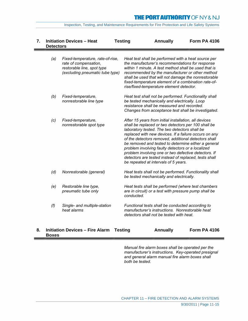
Inspection, Testing, and Maintenance Requirements for Fire Protection and Life Safety Systems
CHAPTER 11 – FIRE DETECTION AND ALARM SYSTEMS 9/30/2011 | Page 11-15
7. Initiation Devices – Heat
Detectors Testing Annually Form PA 4106
(a) Fixed-temperature, rate-of-rise, Heat test shall be performed with a heat source per rate of compensation, the manufacturer’s recommendations for response restorable line, spot type within 1 minute. A test method shall be used that is (excluding pneumatic tube type) recommended by the manufacturer or other method
shall be used that will not damage the nonrestorable fixed-temperature element of a combination rate-of-rise/fixed-temperature element detector.
(b) Fixed-temperature, Heat test shall not be performed. Functionality shall nonrestorable line type be tested mechanically and electrically. Loop
resistance shall be measured and recorded. Changes from acceptance test shall be investigated.
(c) Fixed-temperature, After 15 years from initial installation, all devices nonrestorable spot type shall be replaced or two detectors per 100 shall be
laboratory tested. The two detectors shall be replaced with new devices. If a failure occurs on any of the detectors removed, additional detectors shall be removed and tested to determine either a general problem involving faulty detectors or a localized problem involving one or two defective detectors. If detectors are tested instead of replaced, tests shall be repeated at intervals of 5 years.
(d) Nonrestorable (general) Heat tests shall not be performed. Functionality shall
be tested mechanically and electrically. (e) Restorable line type, Heat tests shall be performed (where test chambers pneumatic tube only are in circuit) or a test with pressure pump shall be
conducted. (f) Single- and multiple-station Functional tests shall be conducted according to heat alarms manufacturer’s instructions. Nonrestorable heat
detectors shall not be tested with heat. 8. Initiation Devices – Fire Alarm
Boxes Testing Annually Form PA 4106
Manual fire alarm boxes shall be operated per the
manufacturer’s instructions. Key-operated presignal and general alarm manual fire alarm boxes shall both be tested.

Inspection, Testing, and Maintenance Requirements for Fire Protection and Life Safety Systems
CHAPTER 11 – FIRE DETECTION AND ALARM SYSTEMS 9/30/2011 | Page 11-16
9. Initiation Devices – Radiant
Energy Fire Detectors Testing Semi-
Annually Form PA 4105
Flame detectors and spark/ember detectors shall be
tested in accordance with the manufacturer’s instructions to determine that each detector is operative. Flame detector and spark/ember detector sensitivity shall be determined using any of the following:
(1) Calibrated test method (2) Manufacturer’s calibrated sensitivity test
instrument (3) Listed control unit arranged for the purpose (4) Other approved calibrated sensitivity test
method that is directly proportional to the input signal from a fire, consistent with the detector listing or approval.
If designed to be field adjustable, detectors found to
be outside of the approved range of sensitivity shall be replaced or adjusted to bring them into the approved range.
Flame detector and spark/ember detector sensitivity
shall not be determined using a light source that administers an unmeasured quantity of radiation at an undefined distance from the detector.
10. Initiation Devices
Supervisory Testing Quarterly Form PA 4104
(a) High- or low-air pressure switch Switch shall be operated. Receipt of signal obtained
where the required pressure is increased or decreased a maximum 70 kPa (10 psi) from the required pressure level shall be verified.
(b) Room temperature switch Switch shall be operated. Receipt of signal to
indicate the decrease in room temperature to 4.4°C (40°F) and its restoration to above 4.4°C (40°F) shall be verified.
(c) Water level switch Switch shall be operated. Receipt of signal indicating
the water level raised or lowered 76.2 mm (3 in.) from the required level within a pressure tank, or 305 mm (12 in.) from the required level of a nonpressure tank, shall be verified, as shall its restoral to required level.

Inspection, Testing, and Maintenance Requirements for Fire Protection and Life Safety Systems
CHAPTER 11 – FIRE DETECTION AND ALARM SYSTEMS 9/30/2011 | Page 11-17
(d) Water temperature switch Switch shall be operated. Receipt of signal to indicate the decrease in water temperature to 4.4°C (40°F) and its restoration to above 4.4°C (40°F) shall be verified.
11. Initiation Devices
Supervisory Testing Semi-
Annually Form PA 4105
(a) Control valve switch Valve shall be operated and signal receipt shall be
verified to be within the first two revolutions of the hand wheel or within one-fifth of the travel distance, or per the manufacturer’s specifications.
(b) Mechanical, electrosonic, Water shall be flowed through an inspector’s test or pressure-type waterflow connection indicating the flow of water equal to that device from a single sprinkler of the smallest orifice size
installed in the system for wet-pipe systems, or an alarm test bypass connection for dry-pipe, pre-action, or deluge systems in accordance with NFPA 25, Standard for the Inspection, Testing, and Maintenance of Water-Based Fire Protection Systems.
12. Emergency Voice/Alarm
Communications Equipment Inspection Semi-
Annually Form PA 4102
Two-way communications include all systems that responders or occupants may use in the event of an emergency
1028.11 Communication systems for areas of refuge,
907.2.12.3 Fire Department Communication Systems
403.12.1 Stairway Communications Systems
13. Emergency Voice/Alarm
Communications Equipment Testing Annually Form PA 4106
(a) Amplifier/tone generators Correct switching and operation of backup
equipment shall be verified. (b) Call-in signal silence Function shall be operated and receipt of correct
visual and audible signals at control panel shall be verified.
(c) Off-hook indicator (ring down) Phone set shall be installed or phone shall be
removed from hook and receipt of signal at control panel shall be verified.

Inspection, Testing, and Maintenance Requirements for Fire Protection and Life Safety Systems
CHAPTER 11 – FIRE DETECTION AND ALARM SYSTEMS 9/30/2011 | Page 11-18
(d) Phone jacks Phone jack shall be visually inspected and communications path through jack shall be initiated.
(e) Phone set Each phone set shall be activated and correct
operation shall be verified. (f) System performance System shall be operated with a minimum of any five
handsets simultaneously. Voice quality and clarity shall be verified.
14. Special Procedures Inspection Semi-
Annually Form PA 4103
15. Special Procedures Testing Annually Form PA 4107 (a) Alarm verification Time delay and alarm response for smoke detector
circuits identified as having alarm verification shall be verified.
(b) Multiplex systems Communications between sending and receiving
units under both primary and secondary power shall be verified.
Communications between sending and receiving
units under open circuit and short circuit trouble conditions shall be verified.
Communications between sending and receiving
units in all directions where multiple communications pathways are provided shall be verified.
If redundant central control equipment is provided,
switchover and all required functions and operations of secondary control equipment shall be verified.
All system functions and features shall be verified in
accordance with manufacturer’s instructions. 16. Special Hazard Equipment Testing Annually Form PA 4107 (a) Abort switch (IRI type) Abort switch shall be operated. Correct sequence
and operation shall be verified. (b) Abort switch (recycle type) Abort switch shall be operated. Development of
correct matrix with each sensor operated shall be verified.
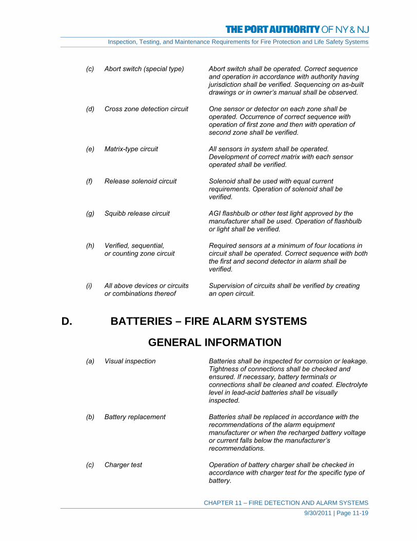
Inspection, Testing, and Maintenance Requirements for Fire Protection and Life Safety Systems
CHAPTER 11 – FIRE DETECTION AND ALARM SYSTEMS 9/30/2011 | Page 11-19
(c) Abort switch (special type) Abort switch shall be operated. Correct sequence
and operation in accordance with authority having jurisdiction shall be verified. Sequencing on as-built drawings or in owner’s manual shall be observed.
(d) Cross zone detection circuit One sensor or detector on each zone shall be
operated. Occurrence of correct sequence with operation of first zone and then with operation of second zone shall be verified.
(e) Matrix-type circuit All sensors in system shall be operated.
Development of correct matrix with each sensor operated shall be verified.
(f) Release solenoid circuit Solenoid shall be used with equal current
requirements. Operation of solenoid shall be verified.
(g) Squibb release circuit AGI flashbulb or other test light approved by the
manufacturer shall be used. Operation of flashbulb or light shall be verified.
(h) Verified, sequential, Required sensors at a minimum of four locations in or counting zone circuit circuit shall be operated. Correct sequence with both
the first and second detector in alarm shall be verified.
(i) All above devices or circuits Supervision of circuits shall be verified by creating or combinations thereof an open circuit. D. BATTERIES – FIRE ALARM SYSTEMS
GENERAL INFORMATION (a) Visual inspection Batteries shall be inspected for corrosion or leakage.
Tightness of connections shall be checked and ensured. If necessary, battery terminals or connections shall be cleaned and coated. Electrolyte level in lead-acid batteries shall be visually inspected.
(b) Battery replacement Batteries shall be replaced in accordance with the
recommendations of the alarm equipment manufacturer or when the recharged battery voltage or current falls below the manufacturer’s recommendations.
(c) Charger test Operation of battery charger shall be checked in
accordance with charger test for the specific type of battery.

Inspection, Testing, and Maintenance Requirements for Fire Protection and Life Safety Systems
CHAPTER 11 – FIRE DETECTION AND ALARM SYSTEMS 9/30/2011 | Page 11-20
(d) Discharge test With the battery charger disconnected, the batteries
shall be load tested following the manufacturer’s recommendations. The voltage level shall not fall below the levels specified.
Exception: An artificial load equal to the full fire alarm load connected to the battery shall be permitted to be used in conducting this test.
(e) Load voltage test With the battery charger disconnected, the terminal
voltage shall be measured while supplying the maximum load required by its application. The voltage level shall not fall below the levels specified for the specific type of battery. If the voltage falls below the level specified, corrective action shall be taken and the batteries shall be retested.
Exception: An artificial load equal to the full fire alarm load connected to the battery shall be permitted to be used in conducting this test.
1. Batteries Inspection Monthly Form PA 4101 Lead-acid Type Primary Type (Dry Cell) 2. Batteries Inspection Semi-
Annually Form PA 4102
Nickel-Cadmium Type Sealed-lead Acid Type 3. Batteries (Lead-acid Type) Testing Semi-
Annually Form PA 4105
1. Discharge test (30 minutes) 2. Load voltage test Under load, the battery shall not fall below 2.05 volts
per cell.
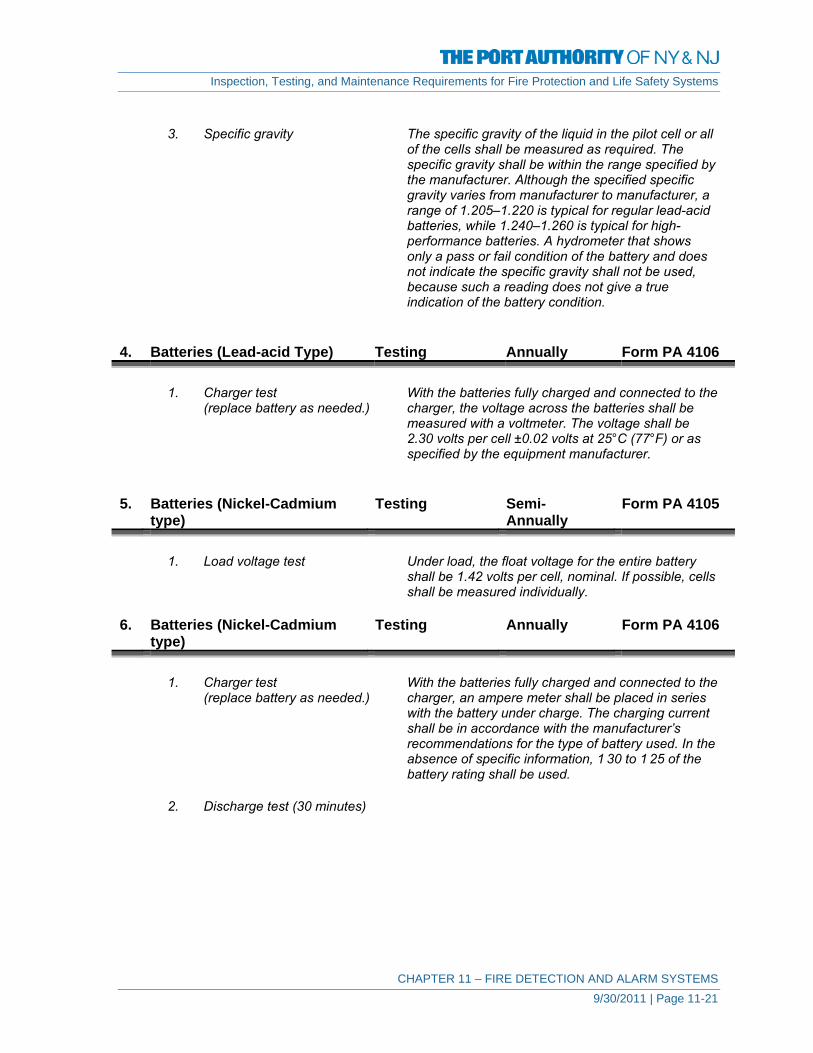
Inspection, Testing, and Maintenance Requirements for Fire Protection and Life Safety Systems
CHAPTER 11 – FIRE DETECTION AND ALARM SYSTEMS 9/30/2011 | Page 11-21
3. Specific gravity The specific gravity of the liquid in the pilot cell or all
of the cells shall be measured as required. The specific gravity shall be within the range specified by the manufacturer. Although the specified specific gravity varies from manufacturer to manufacturer, a range of 1.205–1.220 is typical for regular lead-acid batteries, while 1.240–1.260 is typical for high-performance batteries. A hydrometer that shows only a pass or fail condition of the battery and does not indicate the specific gravity shall not be used, because such a reading does not give a true indication of the battery condition.
4. Batteries (Lead-acid Type) Testing Annually Form PA 4106 1. Charger test With the batteries fully charged and connected to the (replace battery as needed.) charger, the voltage across the batteries shall be
measured with a voltmeter. The voltage shall be 2.30 volts per cell ±0.02 volts at 25°C (77°F) or as specified by the equipment manufacturer.
5. Batteries (Nickel-Cadmium
type) Testing Semi-
Annually Form PA 4105
1. Load voltage test Under load, the float voltage for the entire battery
shall be 1.42 volts per cell, nominal. If possible, cells shall be measured individually.
6. Batteries (Nickel-Cadmium
type) Testing Annually Form PA 4106
1. Charger test With the batteries fully charged and connected to the (replace battery as needed.) charger, an ampere meter shall be placed in series
with the battery under charge. The charging current shall be in accordance with the manufacturer’s recommendations for the type of battery used. In the absence of specific information, 1 30 to 1 25 of the battery rating shall be used.
2. Discharge test (30 minutes)

Inspection, Testing, and Maintenance Requirements for Fire Protection and Life Safety Systems
CHAPTER 11 – FIRE DETECTION AND ALARM SYSTEMS 9/30/2011 | Page 11-22
7. Batteries (Primary type – dry
cell) Testing Monthly Form PA 4104
1. Load voltage test The maximum load for a No. 6 primary battery shall
not be more than 2 amperes per cell. An individual (1.5-volt) cell shall be replaced when a load of 1 ohm reduces the voltage below 1 volt. A 6-volt assembly shall be replaced when a test load of 4 ohms reduces the voltage below 4 volts.
8. Batteries (Sealed lead-acid
type) Testing Semi-
Annually Form PA 4105
1. Load voltage test Under load, the battery shall perform in accordance
with the battery manufacturer’s specifications. 9. Batteries (Sealed lead-acid
type) Testing Annually Form PA 4106
1. Charger test (replace battery With the batteries fully charged and connected to the within 5 years after manufacture charger, the voltage across the batteries shall be or more frequently as needed.) measured with a voltmeter. The voltage shall be
2.30 volts per cell ±0.02 volts at 25°C (77°F) or as specified by the equipment manufacturer.
2. Discharge test (30 minutes) E. CONTROL EQUIPMENT 1. Control Equipment: Fire
Alarm Systems Un-Monitored for Alarm, Supervisory, and Trouble Signals
Inspection Weekly Form PA 4100
(a) Fuses (b) Interfaced equipment (c) Lamps and LEDs (d) Primary (main) power supply
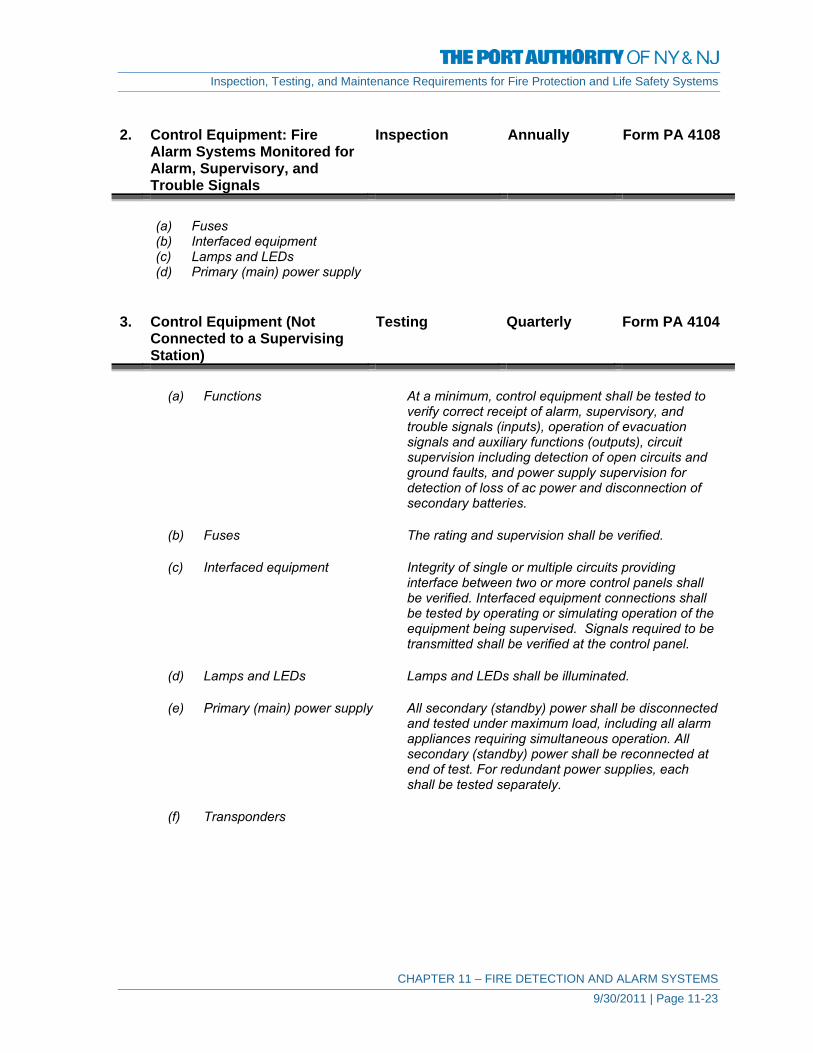
Inspection, Testing, and Maintenance Requirements for Fire Protection and Life Safety Systems
CHAPTER 11 – FIRE DETECTION AND ALARM SYSTEMS 9/30/2011 | Page 11-23
2. Control Equipment: Fire
Alarm Systems Monitored for Alarm, Supervisory, and Trouble Signals
Inspection Annually Form PA 4108
(a) Fuses (b) Interfaced equipment (c) Lamps and LEDs (d) Primary (main) power supply 3. Control Equipment (Not
Connected to a Supervising Station)
Testing Quarterly Form PA 4104
(a) Functions At a minimum, control equipment shall be tested to
verify correct receipt of alarm, supervisory, and trouble signals (inputs), operation of evacuation signals and auxiliary functions (outputs), circuit supervision including detection of open circuits and ground faults, and power supply supervision for detection of loss of ac power and disconnection of secondary batteries.
(b) Fuses The rating and supervision shall be verified. (c) Interfaced equipment Integrity of single or multiple circuits providing
interface between two or more control panels shall be verified. Interfaced equipment connections shall be tested by operating or simulating operation of the equipment being supervised. Signals required to be transmitted shall be verified at the control panel.
(d) Lamps and LEDs Lamps and LEDs shall be illuminated. (e) Primary (main) power supply All secondary (standby) power shall be disconnected
and tested under maximum load, including all alarm appliances requiring simultaneous operation. All secondary (standby) power shall be reconnected at end of test. For redundant power supplies, each shall be tested separately.
(f) Transponders
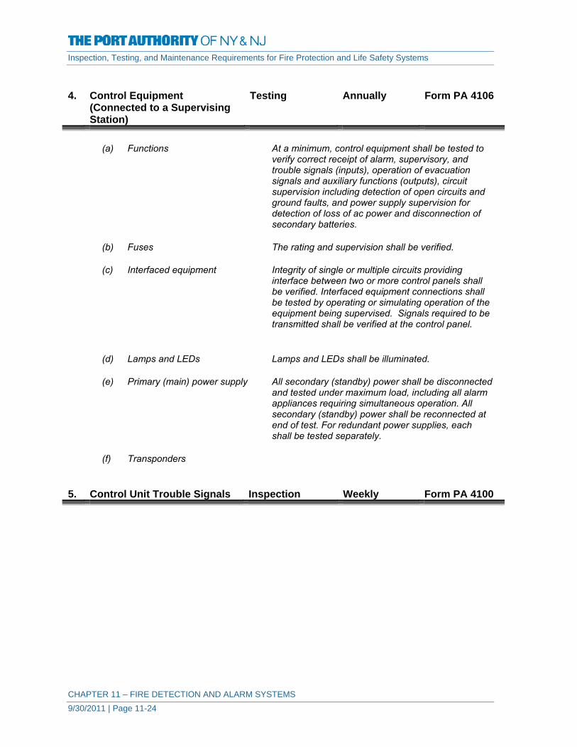
Inspection, Testing, and Maintenance Requirements for Fire Protection and Life Safety Systems
CHAPTER 11 – FIRE DETECTION AND ALARM SYSTEMS 9/30/2011 | Page 11-24
4. Control Equipment
(Connected to a Supervising Station)
Testing Annually Form PA 4106
(a) Functions At a minimum, control equipment shall be tested to
verify correct receipt of alarm, supervisory, and trouble signals (inputs), operation of evacuation signals and auxiliary functions (outputs), circuit supervision including detection of open circuits and ground faults, and power supply supervision for detection of loss of ac power and disconnection of secondary batteries.
(b) Fuses The rating and supervision shall be verified. (c) Interfaced equipment Integrity of single or multiple circuits providing
interface between two or more control panels shall be verified. Interfaced equipment connections shall be tested by operating or simulating operation of the equipment being supervised. Signals required to be transmitted shall be verified at the control panel.
(d) Lamps and LEDs Lamps and LEDs shall be illuminated. (e) Primary (main) power supply All secondary (standby) power shall be disconnected
and tested under maximum load, including all alarm appliances requiring simultaneous operation. All secondary (standby) power shall be reconnected at end of test. For redundant power supplies, each shall be tested separately.
(f) Transponders 5. Control Unit Trouble Signals Inspection Weekly Form PA 4100

Inspection, Testing, and Maintenance Requirements for Fire Protection and Life Safety Systems
CHAPTER 11 – FIRE DETECTION AND ALARM SYSTEMS 9/30/2011 | Page 11-25
6. Control Unit Trouble Signals Testing Annually Form PA 4106 (a) Audible and visual Operation of panel trouble signals shall be verified
as well as ring-back feature for systems using a trouble-silencing switch that requires resetting.
(b) Disconnect switches If control unit has disconnect or isolating switches,
performance of intended function of each switch shall be verified and receipt of trouble signal when a supervised function is disconnected shall also be verified.
(c) Ground-fault monitoring circuit If the system has a ground detection feature, the
occurrence of ground-fault indication shall be verified whenever any installation conductor is grounded.
(d) Transmission of signals to off- An initiating device shall be actuated and receipt of premises location alarm signal at the off-premises location shall be
verified. A trouble condition shall be created and receipt of a trouble signal at the off-premises location shall be verified. A supervisory device shall be actuated and receipt of a supervisory signal at the off-premises location shall be verified. If a transmission carrier is capable of operation under a single- or multiple-fault condition, an initiating device shall be activated during such fault condition and receipt of a trouble signal at the off-premises location shall be verified, in addition to the alarm signal.
7. Remote Annunciators Inspection Semi-
Annually Form PA 4102
8. Remote Annunciators Testing Annually Form PA 4106 Remote Annunciators The correct operation and identification of
annunciators shall be verified. If provided, the correct operation of annunciator under a fault condition shall be verified.
9. Interface Equipment Inspection Semi-
Annually Form PA 4102

Inspection, Testing, and Maintenance Requirements for Fire Protection and Life Safety Systems
CHAPTER 11 – FIRE DETECTION AND ALARM SYSTEMS 9/30/2011 | Page 11-26
10. Interface Equipment Testing Annually Form PA 4107 Interface Equipment Interface equipment connections shall be tested by
operating or simulating the equipment being supervised. Signals required to be transmitted shall be verified at the control panel. Test frequency for interface equipment shall be the same as the frequency required by the applicable NFPA standard(s) for the equipment being supervised.
11. Fiber-Optic Cable
Connections Inspection Annually Form PA 4108
12. Fiber-Optic Cable Power Testing Annually Form PA 4106 Fiber optics The fiber-optic transmission line shall be tested in
accordance with the manufacturer’s instructions by the use of an optical power meter or by an optical time domain reflectometer used to measure the relative power loss of the line. This relative figure for each fiber-optic line shall be recorded in the fire alarm control panel. If the power level drops 2 percent or more from the value recorded during the initial acceptance test, the transmission line, section thereof, or connectors shall be repaired or replaced by a qualified technician to bring the line back into compliance with the accepted transmission level per the manufacturer’s recommendations.
13. Off-Premises Transmission
Equipment Testing Quarterly Form PA 4104
6.12.1 Systems requiring transmission of signals to continuously attended locations
providing supervising station service (e.g., central station, proprietary supervising station, remote supervising station) shall also comply with the applicable requirements of Chapter 8.
6.12.2 Relays or modules providing transmission of trouble signals to a supervising
station shall be arranged to provide fail-safe operation.
6.12.3 Means provided to transmit trouble signals to supervising stations shall be arranged so as to transmit a trouble signal to the supervising station for any trouble condition received at the protected premises control unit, including loss of primary or secondary power.
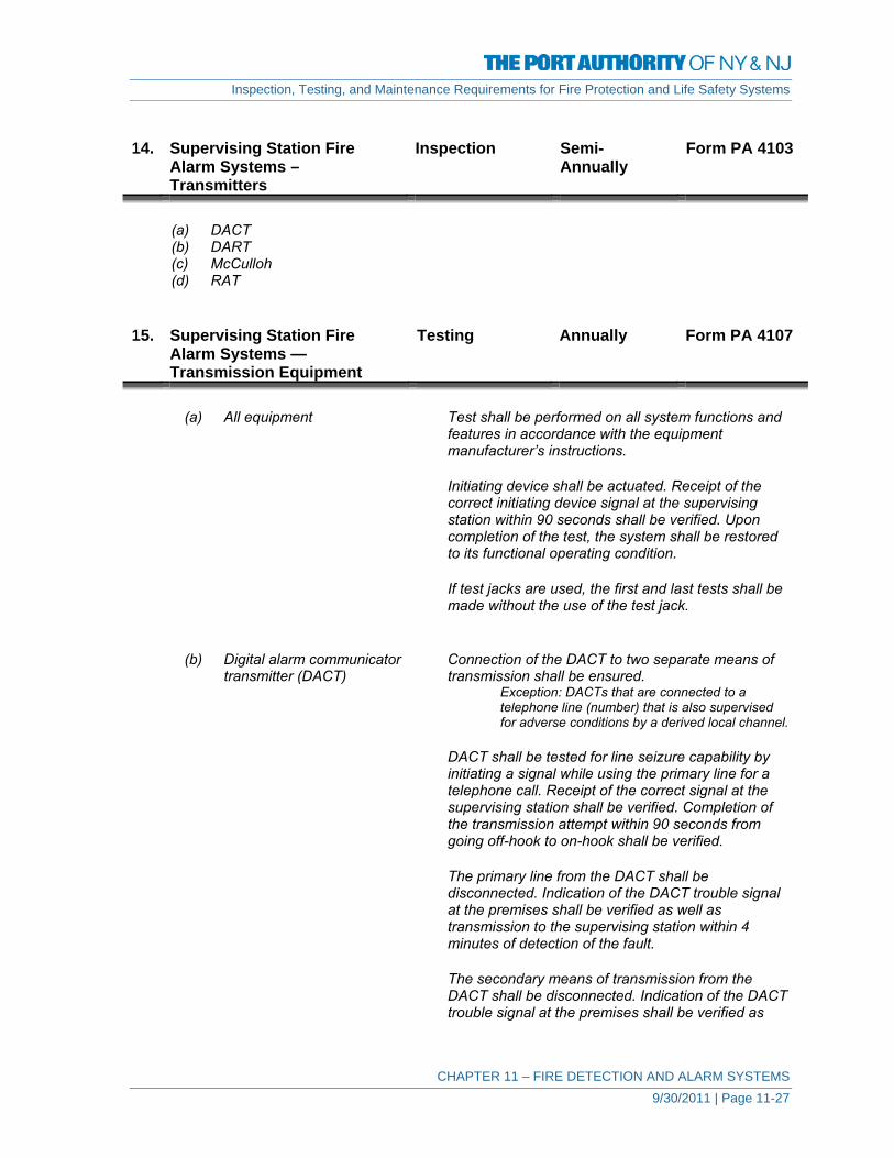
Inspection, Testing, and Maintenance Requirements for Fire Protection and Life Safety Systems
CHAPTER 11 – FIRE DETECTION AND ALARM SYSTEMS 9/30/2011 | Page 11-27
14. Supervising Station Fire
Alarm Systems – Transmitters
Inspection Semi-Annually
Form PA 4103
(a) DACT (b) DART (c) McCulloh (d) RAT 15. Supervising Station Fire
Alarm Systems — Transmission Equipment
Testing Annually Form PA 4107
(a) All equipment Test shall be performed on all system functions and
features in accordance with the equipment manufacturer’s instructions.
Initiating device shall be actuated. Receipt of the
correct initiating device signal at the supervising station within 90 seconds shall be verified. Upon completion of the test, the system shall be restored to its functional operating condition.
If test jacks are used, the first and last tests shall be
made without the use of the test jack. (b) Digital alarm communicator Connection of the DACT to two separate means of transmitter (DACT) transmission shall be ensured.
Exception: DACTs that are connected to a telephone line (number) that is also supervised for adverse conditions by a derived local channel.
DACT shall be tested for line seizure capability by
initiating a signal while using the primary line for a telephone call. Receipt of the correct signal at the supervising station shall be verified. Completion of the transmission attempt within 90 seconds from going off-hook to on-hook shall be verified.
The primary line from the DACT shall be
disconnected. Indication of the DACT trouble signal at the premises shall be verified as well as transmission to the supervising station within 4 minutes of detection of the fault.
The secondary means of transmission from the
DACT shall be disconnected. Indication of the DACT trouble signal at the premises shall be verified as
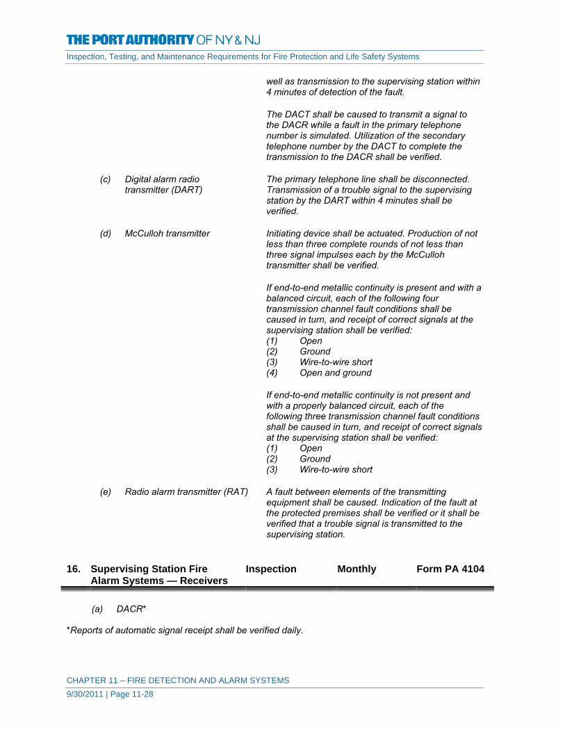
Inspection, Testing, and Maintenance Requirements for Fire Protection and Life Safety Systems
CHAPTER 11 – FIRE DETECTION AND ALARM SYSTEMS 9/30/2011 | Page 11-28
well as transmission to the supervising station within 4 minutes of detection of the fault.
The DACT shall be caused to transmit a signal to
the DACR while a fault in the primary telephone number is simulated. Utilization of the secondary telephone number by the DACT to complete the transmission to the DACR shall be verified.
(c) Digital alarm radio The primary telephone line shall be disconnected. transmitter (DART) Transmission of a trouble signal to the supervising
station by the DART within 4 minutes shall be verified.
(d) McCulloh transmitter Initiating device shall be actuated. Production of not
less than three complete rounds of not less than three signal impulses each by the McCulloh transmitter shall be verified.
If end-to-end metallic continuity is present and with a
balanced circuit, each of the following four transmission channel fault conditions shall be caused in turn, and receipt of correct signals at the supervising station shall be verified:
(1) Open (2) Ground (3) Wire-to-wire short (4) Open and ground
If end-to-end metallic continuity is not present and
with a properly balanced circuit, each of the following three transmission channel fault conditions shall be caused in turn, and receipt of correct signals at the supervising station shall be verified:
(1) Open (2) Ground (3) Wire-to-wire short
(e) Radio alarm transmitter (RAT) A fault between elements of the transmitting
equipment shall be caused. Indication of the fault at the protected premises shall be verified or it shall be verified that a trouble signal is transmitted to the supervising station.
16. Supervising Station Fire
Alarm Systems — Receivers Inspection Monthly Form PA 4104
(a) DACR* *Reports of automatic signal receipt shall be verified daily.

Inspection, Testing, and Maintenance Requirements for Fire Protection and Life Safety Systems
CHAPTER 11 – FIRE DETECTION AND ALARM SYSTEMS 9/30/2011 | Page 11-29
17. Supervising Station Fire
Alarm Systems — Receivers Inspection Semi-
Annually Form PA 4103
(b) DARR* (c) McCulloh systems* (d) Two-way RF multiplex* (e) RASSR* (f) RARS* (g) Private microwave* *Reports of automatic signal receipt shall be verified daily. 18. Supervising Station Fire
Alarm Systems — Receiving Equipment
Testing Monthly Form PA 4107
(a) All equipment Tests shall be performed on all system functions and
features in accordance with the equipment manufacturer’s instructions for correct operation in conformance with the applicable sections of Chapter 8 – NFPA 72 (2002).
Initiating device shall be actuated. Receipt of the
correct initiating device signal at the supervising station within 90 seconds shall be verified. Upon completion of the test, the system shall be restored to its functional operating condition.
If test jacks are used, the first and last tests shall be
made without the use of the test jack. (b) Digital alarm communicator Each telephone line (number) shall be disconnected receiver (DACR) in turn from the DACR and audible and visual
annunciation of a trouble signal in the supervising station shall be verified.
A signal shall be caused to be transmitted on each
individual incoming DACR line at least once every 24 hours. Receipt of these signals shall be verified.
(c) Digital alarm radio The following conditions of all DARRs on all
subsidiary receiver (DARR) and repeater station receiving equipment shall be caused. Receipt at the supervising station of correct signals for each of the following conditions shall be verified:
(1) AC power failure of the radio equipment (2) Receiver malfunction (3) Antenna and interconnecting cable failure

Inspection, Testing, and Maintenance Requirements for Fire Protection and Life Safety Systems
CHAPTER 11 – FIRE DETECTION AND ALARM SYSTEMS 9/30/2011 | Page 11-30
(4) Indication of automatic switchover of the DARR
(5) Data transmission line failure between the DARR and the supervising or subsidiary station
(d) McCulloh systems The current on each circuit at each supervising and
subsidiary station under the following conditions shall be tested and recorded:
(1) During functional operation (2) On each side of the circuit with the receiving
equipment conditioned for an open circuit A single break or ground condition shall be caused
on each transmission channel. If such a fault prevents the functioning of the circuit, receipt of a trouble signal shall be verified.
Each of the following conditions at each of the
supervising or subsidiary stations and all repeater station radio transmitting and receiving equipment shall be caused; receipt of correct signals at the supervising station shall be verified:
(1) RF transmitter in use (radiating) (2) AC power failure supplying the radio
equipment (3) RF receiver malfunction (4) Indication of automatic switchover
(e) Radio alarm supervising station Each of the following conditions at each of the receiver (RASSR) and radio supervising or subsidiary stations and all repeater alarm repeater station station radio transmitting and receiving equipment receiver (RARSR) shall be caused; receipt of correct signals at the
supervising station shall be verified: (1) AC power failure supplying the radio
equipment (2) RF receiver malfunction (3) Indication of automatic switchover, if
applicable (f) Private microwave radio systems Each of the following conditions at each of the
supervising or subsidiary stations and all repeater station radio transmitting and receiving equipment shall be caused; receipt of correct signals at the supervising station shall be verified:
(1) RF transmitter in use (radiating) (2) AC power failure supplying the radio
equipment (3) RF receiver malfunction (4) Indication of automatic switchover

Inspection, Testing, and Maintenance Requirements for Fire Protection and Life Safety Systems
CHAPTER 11 – FIRE DETECTION AND ALARM SYSTEMS 9/30/2011 | Page 11-31
19. Low-Power Radio – Wireless
Systems Inspection Monthly Form PA 4101
(1) Batteries for all components in the system shall be
checked monthly. If the control panel checks all batteries and all components daily, the system shall not require monthly testing of the batteries.
20. Low-Power Radio – Wireless
Systems Testing Annually Form PA 4107
The following procedures describe additional
acceptance and reacceptance test methods to verify wireless protection system operation:
(1) The manufacturer’s manual and the as-built
drawings provided by the system supplier shall be used to verify correct operation after the initial testing phase has been performed by the supplier or by the supplier’s designated representative.
(2) Starting from the functional operating condition, the
system shall be initialized in accordance with the manufacturer’s manual. A test shall be conducted to verify the alternative path, or paths, by turning off or disconnecting the primary wireless repeater. The alternative communications path shall exist between the wireless control panel and peripheral devices used to establish initiation, indication, control, and annunciation. The system shall be tested for both alarm and trouble conditions.

FIRE DETECTION AND ALARM SYSTEMS - GENERAL INFORMATION - PA 4097 / 02-12 FIRE ALARM CONTROL PANELS
Original Installation Date: U.E.I. (Unique Element Identification) :
Date: Building ID: FACP ID:
Fire Alarm Panels Fire Alarm Panel - Make/Model/Manufacturer:
Fire Alarm Panel – Location:
Signals Transmitted to:
Emergency Power provided by:
Identify Number and Location of SubPanels, Nodes, DGPs, Annunciator panels, Smoke Management panels, Fire Suppression Releasing panels, etc., connected to this fire alarm panel. Provide unique identifier for each. Use reverse side of form if necessary.
Alarm Notification Devices Total number of Audible Notification Devices:
Total number of Visual Notification Devices:
Alarm Initiating Devices Total number of Smoke Detection Devices:
Total number of Heat Detection Devices:
Total number of Manual Pull Stations:
Number of Water Flow Alarm Signals:
Number of Tamper Switch signals:
Number of Supervisory Signals:
Number/Description of Other Alarm Initiating Devices:
Special Functions
Smoke Purge / Smoke Management Systems Yes No
Releasing Devices i.e. Electromagnetic Locks, Electric Strike Locks, Door Hold Open Devices, etc. Yes No
Emergency Voice/Alarm Communications Systems Yes No
Fire Suppression System Activation i.e., FM200 systems, Deluge Sprinkler Systems, Dry Chemical Extinguishing Systems, etc.
Yes
No
Other Fire Alarm System Special Functions:
Notes:

FIRE DETECTION AND ALARM SYSTEMS - GENERAL INFORMATION - PA 4098 / 02-12 ALARM INITIATING DEVICES
Date: Building ID: FACP ID:
Total Number of Alarm Initiating Devices:
1. Device Identification - Provide unique identifier for each Alarm Initiating Device 2. Provide location of Alarm Initiating Device
3. Identify Type of Alarm Initiating Device i.e., Smoke Detector, Manual Pull Station, Sprinkler Water Flow Alarm, Clean Agent
Discharge, etc. 4. Provide Date Alarm Initiating Device was installed. 5. Provide any other information in Notes.
Device ID U.E.I. Location Type of Alarm
Initiating Device Date Installed Notes

FIRE DETECTION AND ALARM SYSTEMS - GENERAL INFORMATION - PA 4099 / 02-12 ALARM NOTIFICATION DEVICES
Date: Building ID: FACP ID:
Total Number of Alarm Notification Devices:
1. Device Identification - Provide unique identifier for each Alarm Notification Device 2. Provide location of Alarm Notification Device 3. Identify Type of Alarm Notification Device i.e., Horn, Bell, Horn/Strobe, Strobe, Voice Speaker 4. Provide Date Alarm Notification Device was installed. 5. Provide any other information in Notes.
Device ID U.E.I. Location Type of Alarm
Notification Device Date Installed Notes

FIRE DETECTION AND ALARM SYSTEMS - WEEKLY INSPECTION PA 4100 / 02-12
Building ID: FACP ID:
Y = Satisfactory N = Unsatisfactory (explain below) N/A = Not applicable
Date:
Inspector
Control Equipment for Fire Alarm Systems Unmonitored for Alarm, Supervisory, and Trouble Signals.
Fuses
Interface Equipment
Lamps and LEDs
Primary (Main) Power Supply
Control Panel Trouble Signal
Notes:

FIRE DETECTION AND ALARM SYSTEMS - PA 4101 / 02-12MONTHLY / QUARTERLY INSPECTIONS
Building ID: FACP ID:
Y = Satisfactory N = Unsatisfactory (explain on reverse) N/A = Not applicable
Monthly Inspection
Date:
Inspector:
Engine driven generator facility & alarm systems:
Lead-acid battery:
Dry-cell primary battery:
Low-Power Radio – Wireless Systems:
DACR - Receiver(s):
Quarterly Inspection
Date:
Inspector:
Radiant energy fire detectors:
Supervisory signal devices:
Waterflow devices:
Notes:

FIRE DETECTION AND ALARM SYSTEMS - SEMI-ANNUAL INSPECTION (Page 1 of 2) PA 4102 / 02-12
Building ID: ACP ID:
Identify the Number of Devices or Systems inspected and specify device or system information on the reverse side of this form.
Date:
Inspector:
Nickel-Cadmium Batteries Inspected
Sealed Lead-Acid Batteries Inspected
Transient suppressors
Control panel trouble signals
Emergency Voice/Alarm Communications Equipment Inspected
Number of Remote Annunciators Inspected
Air-sampling initiating devices
Number of Duct Smoke Detectors Inspected
Number of Electromechanical Releasing Devices Inspected
Number of Fire Extinguishing System Switches Inspected
Number of Fire Suppression System Switches Inspected
Number of Fire alarm boxes (manual stations) Inspected
Number of Heat Detectors Inspected
Number of Smoke Detectors Inspected
Interface Equipment Inspected
Number of Alarm Notification Appliances Inspected
Notes:
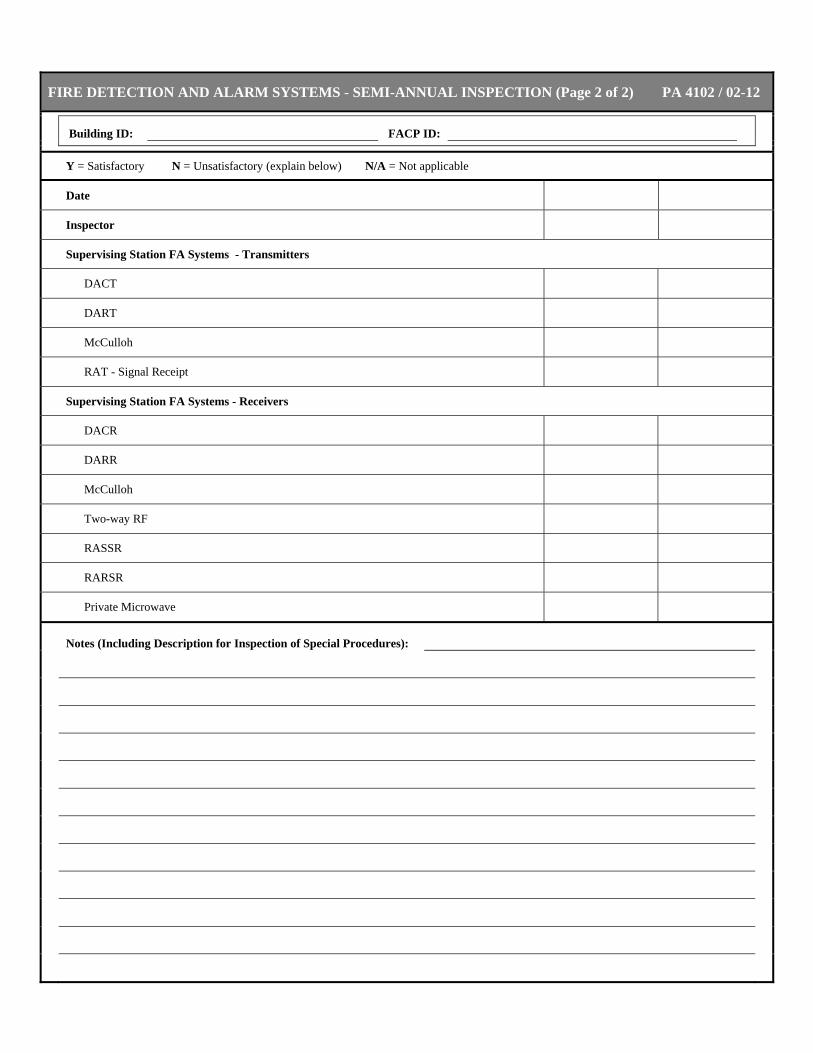
FIRE DETECTION AND ALARM SYSTEMS - SEMI-ANNUAL INSPECTION (Page 2 of 2) PA 4102 / 02-12
Building ID: FACP ID:
Y = Satisfactory N = Unsatisfactory (explain below) N/A = Not applicable
Date
Inspector
Supervising Station FA Systems - Transmitters
DACT
DART
McCulloh
RAT - Signal Receipt
Supervising Station FA Systems - Receivers
DACR
DARR
McCulloh
Two-way RF
RASSR
RARSR
Private Microwave
Notes (Including Description for Inspection of Special Procedures):

FIRE DETECTION AND ALARM SYSTEMS - MONTHLY/QUARTERLY TESTS PA 4104 / 02-12
Building ID: FACP ID:
Y = Satisfactory N = Unsatisfactory (explain below) N/A = Not applicable
Monthly Test
Date:
Inspector:
Load voltage for dry-cell batteries:
Monthly Test - Supervising Station FA System - Receivers
Receivers - All Equipment:
DACR:
DARR:
McCulloh System:
Two-way RF Multiplex:
RASSR:
RARSR:
Private Microwave:
Quarterly Test (for Fire Alarm Systems having Unmonitored Signals)
Date:
Inspector:
Functions:
Fuses:
Interfaced equipment:
Lamps and LEDs:
Primary (main) power supply:
Transponders:
Supervisory signal devices except tamper switches:
Off-premises transmission equipment:
Notes:
Continue on reverse if necessary

FIRE DETECTION AND ALARM SYSTEMS - SEMI-ANNUAL TEST PA 4105 / 02-12
Building ID: FACP ID
Y = Satisfactory N = Unsatisfactory (explain below) N/A = Not applicable
Date
Inspector
Lead-acid battery discharge test
Lead-acid battery load voltage test
Lead-acid battery specific gravity
Nickel-cadmium battery load voltage test
Sealed lead-acid battery load voltage test
Radiant Energy Fire Detectors
Control Valve Tamper Switches
Waterflow Devices
Notes:
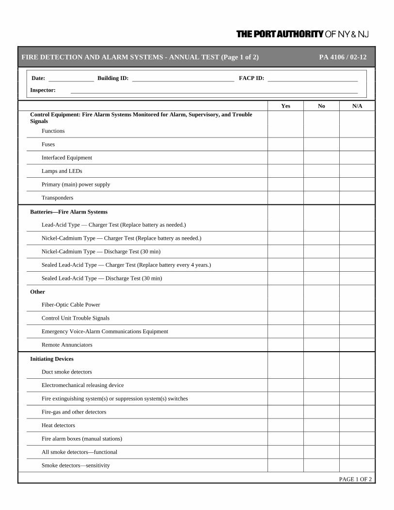
FIRE DETECTION AND ALARM SYSTEMS - ANNUAL TEST (Page 1 of 2) PA 4106 / 02-12
Date: Building ID: FACP ID:
Inspector:
Yes No N/A
Control Equipment: Fire Alarm Systems Monitored for Alarm, Supervisory, and Trouble Signals
Functions
Fuses
Interfaced Equipment
Lamps and LEDs
Primary (main) power supply
Transponders
Batteries—Fire Alarm Systems
Lead-Acid Type — Charger Test (Replace battery as needed.)
Nickel-Cadmium Type — Charger Test (Replace battery as needed.)
Nickel-Cadmium Type — Discharge Test (30 min)
Sealed Lead-Acid Type — Charger Test (Replace battery every 4 years.)
Sealed Lead-Acid Type — Discharge Test (30 min)
Other
Fiber-Optic Cable Power
Control Unit Trouble Signals
Emergency Voice-Alarm Communications Equipment
Remote Annunciators
Initiating Devices
Duct smoke detectors
Electromechanical releasing device
Fire extinguishing system(s) or suppression system(s) switches
Fire-gas and other detectors
Heat detectors
Fire alarm boxes (manual stations)
All smoke detectors—functional
Smoke detectors—sensitivity
PAGE 1 OF 2

FIRE DETECTION AND ALARM SYSTEMS - ANNUAL TEST (Page 2 of 2) PA 4106 / 02-12
Date: Building ID: FACP ID:
Inspector:
Yes No N/A
Interface Equipment
Special Hazard Equipment
Alarm Notification Appliances
Audible devices
Speakers
Visible devices
Supervising Station FA Systems - Transmitters
Transmitters - All Equipment
DACT
DART
McCulloh
RAT
Supervising Station FA Systems - Receivers
DACR
DARR
McCulloh
RASSR
RARSR
Private Microwave
Low-Power Radio – Wireless Systems
Notes (Including Description for Tests of Special Procedures):
PAGE 2 OF 2

FIRE DETECTION AND ALARM SYSTEMS - ANNUAL INSPECTION PA 4108 / 02-12
Date: Building ID: FACP ID:
Location:
Y = Satisfactory N = Unsatisfactory (explain below) N/A = Not applicable
Date
Inspector
Monitored FA System Control Equipment
Fuses
Interface equipment
Lamp & LEDs
Primary (main) power supply
Fiber Optic Cable Connection
Notes:

Inspection, Testing, and Maintenance Requirements for Fire Protection and Life Safety Systems
CHAPTER 12 – EMERGENCY AND STANDBY POWER SYSTEMS 9/30/2011 | Page 12-1
CHAPTER 12 – EMERGENCY AND STANDBY POWER
SYSTEMS
DEFINITIONS Emergency Power Supply (EPS) The source of electric power of the required capacity and
quality for an emergency power supply system (EPSS). Emergency Power Supply System A complete functioning EPS system coupled to a system of (EPSS) conductors, disconnecting means and overcurrent protective
devices, transfer switches, and all control, supervisory, and support devices up to and including the load terminals of the transfer equipment needed for the system to operate as a safe and reliable source of electric power.
Day Fuel Tank A fuel tank, located inside a structure, that provides fuel to
the engine. Enclosed Fuel Tank A fuel tank located within a separate room, separated from
other equipment. Integral Fuel Tank A fuel tank furnished by the EPS manufacturer and mounted
on the engine or the engine subbase. Main Fuel Tank A separate, main fuel tank for supplying fuel to the engine or
a day tank. Automatic Transfer Switch Self-acting equipment for transferring one or more load
conductor connections from one power source to another. Bypass-Isolation Switch A manually operated device used in conjunction with an
automatic transfer switch to provide a means of directly connecting load conductors to a power source and disconnecting the automatic transfer switch.
Nonautomatic Transfer Switch A device, operated by direct manpower or electrical remote
manual control, for transferring one or more load conductor connections from one power source to another.
Level 1 systems Installed when failure of the equipment to perform could
result in loss of human life or serious injuries. Level 2 systems Installed when failure of the EPSS or SEPSS to perform is
less critical to human life and safety and where the authority having jurisdiction shall permit a higher degree of flexibility than provided by a Level 1 system.

Inspection, Testing, and Maintenance Requirements for Fire Protection and Life Safety Systems
CHAPTER 12 – EMERGENCY AND STANDBY POWER SYSTEMS 9/30/2011 | Page 12-2
Stored Emergency Power Supply A system consisting of a UPS, a central battery system, or a System (SEPSS) motor generator, powered by a stored electrical energy
source, together with a transfer switch designed to monitor preferred and alternate load power source and provide desired switching of the load, and all necessary control equipment to make the system functional.
Uninterrupted Power Supply (UPS) A system consisting of a battery source, a converter, an
inverter, and control equipment designed to provide a clean, conditioned sinusoidal wave of power for a finite period of time.
A. Emergency and Standby Power Systems 1. Existing Emergency Power
Supply Systems General Information
Update Annually Form PA 4110
Review General Information Form for all Emergency Power Supply Systems, update as required.
Confirm that the instruction manuals, drawings, and documentation for routine maintenance and operational testing are provided as identified in 2 below.
2. New or Altered Emergency
Power Supply Systems General Information
Update As Required Form PA 4110
Complete General Information Form for new Emergency Power Supply Systems or update General Information Form for Emergency Power Supply Systems that has been altered to include repairs and/or modifications to components.
Confirm that the instruction manuals and drawings are provided as required:
8.2.1 At least two sets of instruction manuals for all major components of the
EPSS shall be supplied by the manufacturer(s) of the EPSS and shall contain the following: (1) A detailed explanation of the operation of the system (2) Instructions for routine maintenance (3) Detailed instructions for repair of the EPS and other major
components of the EPSS (4) An illustrated parts list and part numbers (5) Illustrated and schematic drawings of electrical wiring systems,
including operating and safety devices, control panels, instrumentation, and annunciators

Inspection, Testing, and Maintenance Requirements for Fire Protection and Life Safety Systems
CHAPTER 12 – EMERGENCY AND STANDBY POWER SYSTEMS 9/30/2011 | Page 12-3
8.2.2 For Level 1 systems, instruction manuals shall be kept in a secure, convenient location, one set near the equipment, and the other set in a separate location.
8.2.3 Special tools and testing devices necessary for routine maintenance shall be
available for use when needed.
8.2.4 Replacement for parts identified by experience as high mortality items shall be maintained in a secure location(s) on the premises.
8.2.4.1 Consideration shall be given to stocking spare parts as recommended by the
manufacturer.
Confirm that documentation for routine maintenance and operational testing is on-site
8.3.3 A written schedule for routine maintenance and operational testing of the EPSS shall be established.
8.3.4 A written record of the EPSS inspections, tests, exercising, operation, and
repairs shall be maintained on the premises.
8.3.4.1 The written record shall include the following: (1) The date of the maintenance report (2) Identification of the servicing personnel (3) Notation of any unsatisfactory condition and the corrective action
taken, including parts replaced (4) Testing of any repair for the time as recommended by the
manufacturer 3. Emergency Generator
Operations Inspection Weekly Form PA 4111
8.4.1 EPSSs, including all appurtenant components, shall be inspected
weekly and exercised under load at least monthly. 4. Emergency Generator
Operations Testing Monthly Form PA 4112
8.4.1 EPSSs, including all appurtenant components, shall be inspected weekly and
exercised under load at least monthly.
8.4.2 Diesel generator sets in service shall be exercised at least once monthly, for a minimum of 30 minutes, using one of the following methods: (1) Loading that maintains the minimum exhaust gas temperatures as
recommended by the manufacturer. (2) Under operating temperature conditions and at not less than 30
percent of the EPS nameplate kW rating. (3) If the engine cannot be loaded as required in (2), the engine shall
be operated until the water temperature and the oil pressure have

Inspection, Testing, and Maintenance Requirements for Fire Protection and Life Safety Systems
CHAPTER 12 – EMERGENCY AND STANDBY POWER SYSTEMS 9/30/2011 | Page 12-4
stabilized and then the test shall be terminated before the 30 minute time period expires.
8.4.2.1 The date and time of day for required testing shall be decided by the owner,
based on facility operations.
8.4.2.2 Equivalent loads used for testing shall be automatically replaced with the emergency loads in case of failure of the primary source.
8.4.2.3 Diesel-powered EPS installations that do not meet the requirements of 8-4.2
shall be exercised monthly with the available EPSS load and exercised annually with supplemental loads at 25 percent of nameplate rating for 30 minutes, followed by 50 percent of nameplate rating for 30 minutes, followed by 75 percent of nameplate rating for 60 minutes, for a total of 2 continuous hours.
8.4.2.4 Spark-ignited generator sets in service shall be exercised at least once
monthly, for a minimum of 30 minutes, using one of the following methods: (1) Loading that maintains the minimum exhaust gas temperatures as
recommended by the manufacturer (2) Under operating temperature conditions and at not less than 30
percent of the EPS nameplate kW rating
8.4.2.4.1 The date and time of day for required testing shall be decided by the owner, based on facility operations.
8.4.2.4.2 Equivalent loads used for testing shall be automatically replaced with the
emergency loads in case of failure of the primary source.
8.4.3 The EPS test can be initiated by simulating a power outage using the test switch(es) on the ATSs or by opening a normal breaker. Opening a normal breaker shall not be required.
8.4.4 Load tests of generator sets shall include complete cold starts.
5. Emergency Generator
Operations Testing Annually Form PA 4115
8.4.2.3 Diesel-powered EPS installations that do not meet the requirements of 8-4.2
shall be exercised monthly with the available EPSS load and exercised annually with supplemental loads at 25 percent of nameplate rating for 30 minutes, followed by 50 percent of nameplate rating for 30 minutes, followed by 75 percent of nameplate rating for 60 minutes, for a total of 2 continuous hours.
6. Emergency Generator
Operations Testing 3 Years Form PA 4115
8.4.9 Level 1 EPSS shall be tested for the duration of its assigned class (see
Section 4.2), for at least 4 hours, at least once within every 36 months.

Inspection, Testing, and Maintenance Requirements for Fire Protection and Life Safety Systems
CHAPTER 12 – EMERGENCY AND STANDBY POWER SYSTEMS 9/30/2011 | Page 12-5
8.4.9.1 The load shall be the EPSS system load running at the time of the test. The
test shall be initiated by opening all switches or breakers supplying normal power to the EPSS.
8.4.9.2 A power interruption to non-EPSS loads shall not be required.
A.8.4.9 The intent of this requirement is to provide reasonable assurance that the
EPSS with all of its auxiliary subsystems is capable of running for the duration of its assigned class with its running load. A full facility power outage is not intended for this test but is recommended where a total facility power outage has not occurred within the last 36 months. Supplemental load banks are not required. After the test, the fuel supply should be replenished if necessary.
7. Transfer Switch Testing Monthly Form PA 4112
8.4.6 Transfer switches shall be operated monthly. 8.4.6.1 The monthly test of a transfer switch shall consist of electrically operating the
transfer switch from the standard position to the alternate position and then a return to the standard position.
8. Transfer Switch Maintenance As Required Form PA 4114
8.3.5 Transfer switches shall be subjected to a maintenance program that includes all of the following operations: (1) Checking of connections (2) Inspection or testing for evidence of overheating and excessive
contact erosion (3) Removal of dust and dirt (4) Replacement of contacts when required
9. Circuit Breakers Testing Annually Form PA 4115
8.4.7 EPSS circuit breakers for Level 1 system usage, including main and feed breakers between the EPS and the transfer switch load terminals, shall be exercised annually with the EPS in the “off” position.
10. Circuit Breakers Testing Semi-
Annually Form PA 4112
8.4.7.1 Circuit breakers rated in excess of 600 volts for Level 1 system usage shall
be exercised every 6 months and shall be tested under simulated overload conditions every 2 years.

Inspection, Testing, and Maintenance Requirements for Fire Protection and Life Safety Systems
CHAPTER 12 – EMERGENCY AND STANDBY POWER SYSTEMS 9/30/2011 | Page 12-6
11. Circuit Breakers Testing 2 Years Form PA 4115
8.4.7.1 Circuit breakers rated in excess of 600 volts for Level 1 system usage shall be exercised every 6 months and shall be tested under simulated overload conditions every 2 years.
12. Paralleling Gear Inspection,
Testing, Maintenance
As Required Form PA 4111
8.3.6 Paralleling gear shall be subject to inspection, testing, and maintenance
program that includes all of the following operations: (1) Checking of connections (2) Inspection or testing for evidence of overheating and excessive
contact erosion (3) Removal of dust and dirt (4) Replacement of contacts when required Document results in the Notes on Form PA 4111.
13. Storage Batteries Inspection,
Maintenance Weekly Form PA 4111
8.3.7 Storage batteries, including electrolyte levels or battery voltage, used in
connection with systems shall be inspected weekly and maintained in full compliance with manufacturer’s specifications.
8.3.7.2 Defective batteries shall be replaced immediately upon discovery of defects.
14. Storage Batteries Testing Quarterly Form PA 4112
A.8.3.7 A battery load test should be performed quarterly. 15. Lead-Acid Batteries Testing Monthly Form PA 4112
8.3.7.1 Maintenance of lead-acid batteries shall include the monthly testing and recording of electrolyte specific gravity. Battery conductance testing shall be permitted in lieu of the testing of specific gravity when applicable or warranted.
8.3.7.2 Defective batteries shall be replaced immediately upon discovery of defects.

Inspection, Testing, and Maintenance Requirements for Fire Protection and Life Safety Systems
CHAPTER 12 – EMERGENCY AND STANDBY POWER SYSTEMS 9/30/2011 | Page 12-7
16. Fuel Testing Annually Form PA 4115
8.3.8 A fuel quality test shall be performed at least annually using tests approved by ASTM standards.
17. Emergency Power Supply
Systems Maintenance As Required Forms PA
4111, 4112, 4113, 4114, 4115
8.3.1 The EPSS shall be maintained to ensure to a reasonable degree that the
system is capable of supplying service within the time specified for the type and for the time duration specified for the class.
8.3.2 A routine maintenance and operational testing program shall be initiated
immediately after the EPSS has passed acceptance tests or after completion of repairs that impact the operational reliability of the system.
8.3.2.1 The operational test shall be initiated at an automatic transfer switch and
shall include testing of each EPSS component on which maintenance or repair has been performed, including the transfer of each automatic and manual transfer switch to the alternate power source, for a period of not less than 30 minutes under operating temperature.
A.8.3.1 The suggested maintenance procedure and frequency should follow those
recommended by the manufacturer. In the absence of such recommendations, Figure A.8.3.1(a) indicates alternate suggested procedures.

Inspection, Testing, and Maintenance Requirements for Fire Protection and Life Safety Systems
CHAPTER 12 – EMERGENCY AND STANDBY POWER SYSTEMS 9/30/2011 | Page 12-8
FIGURE A8.3.1(a)
W - Weekly S - Semiannually
M - Monthly A - Annually
Q - Quarterly Nos. indicated hours
Visual
Inspection Check Change Clean Test Level 1 Form
1. Fuel
( a ) Main supply tank level X W 4111( b ) Day tank level X X W 4111( c ) Day tank float switch X X W 4111( d ) Supply or transfer pump
operationX X W 4111
( e ) Solenoid valve operation X X W 4111( f ) Strainer, filter and/or dirt leg X Q 4113( g ) Water in system X X W 4111( h ) Flexible hose and connectors X R W 4111( i ) Tank vents/overflow pipe
blocked X X A 4115
( j ) Piping X A 4114( k ) Fuel in main tank (when used) R A 4112
2. Lubrication System ( a ) Oil level X X W 4111( b ) Oil change R 50 or A 4114( c ) Oil filter R 50 or A 4114( d ) Lube Oil heater X W 4111( e ) Crankcase breather X R X Q 4113
3. Cooling System ( a ) Level X X W 4111( b ) Antifreeze protection level X S 4112( c ) Antifreeze R A 4114( d ) Adequate cooling water to
heat exchangerX W 4111
( e ) Rod out heat exchanger X A 4114( f ) Adequate fresh air through
radiatorX W 4111
( g ) Clean exterior of radiator X A 4114( h ) Fan and alternator belts X X M 4113( i ) Water pump X W 4111( j ) Condition of flexible hoses
and connection X X W 4111
( k ) Jacket water heater X W 4111( l ) Inspect ductwork, clean
louversX X X A 4114
( m ) Louver motor and controls X X X A 4115
Maintenance Schedule
Frequency ProcedureX - Action
R - Replace, if needed
Component (as applicable)

Inspection, Testing, and Maintenance Requirements for Fire Protection and Life Safety Systems
CHAPTER 12 – EMERGENCY AND STANDBY POWER SYSTEMS 9/30/2011 | Page 12-9
FIGURE A8.3.1(a)
W - Weekly S - Semiannually
M - Monthly A - Annually
Q - Quarterly Nos. indicated hours
Visual
Inspection Check Change Clean Test Level 1 Form
4. Exhaust System ( a ) Leakage X W 4111( b ) Drain condensate trap X W 4111( c ) Insulation and fire hazards X Q 4113( d ) Excessive back pressure X A 4115( e ) Exhaust system hangers and
supportsX A 4114
( f ) Flexible exhaust section X S 4114
5. Battery System ( a ) Electrolyte Level X W 4111( b ) Terminals clean and tight X X Q 4113( c ) Remove corrosion/case ext.
clean and dry X X M 4113
( d ) Specific Gravity or state ofcharge
X M 4112
( e ) Charger and charge rate X M 4113( f ) Equalize charge X M 4113
6. Electrical System
( a ) General inspection X W 4111( b ) Tighten controls and power
wiring connectionsX A 4114
( c ) Wire chafing where subject to movement
X X Q 4113
( d ) Operation of safeties and alarms X X S 4112
( e ) Boxes, panels, and cabinets X S 4114( f ) Circuit breakers, fuses
(Do not break manufacturer's seal or perform internal inspections)
X X R X X M 4112
( g ) Transfer switch main contacts X X A 4114( h ) Calibration of voltage‐sensing
relays/devices X X A 4115
( i ) Wire insulation breakdown X 5/500 a 41157. Prime Mover
( a ) General inspection X W 4111( b ) Service air cleaner R X S 4114( c ) Governor oil level and linkage X X M 4113( d ) Governor oil R A 4114
Maintenance Schedule (continued)
Procedure FrequencyX - Action
R - Replace, if needed
Component (as applicable)

Inspection, Testing, and Maintenance Requirements for Fire Protection and Life Safety Systems
CHAPTER 12 – EMERGENCY AND STANDBY POWER SYSTEMS 9/30/2011 | Page 12-10
FIGURE A8.3.1(a)
W - Weekly S - Semiannually
M - Monthly A - Annually
Q - Quarterly Nos. indicated hours
Visual
Inspection Check Change Clean Test Level 1 Form( e ) Ignition system ‐ plugs, points,
coil, cap, rotor, secondary wireinsulation
X X R X X A 4115
( f ) Choke setting and carburetor adjustment X S 4114
( g ) Injector pump and injectors forflow rate, pressure, and/or spray pattern
X A 4115
( h ) Test EPS for 4 hours, at min. 80% of nameplate rating X 3/4c 4115
( i ) Valve clearance X 3/500 b 4115( j ) Torque bolts X 3/500 b 4115
8. Generator ( a ) Brush length, appearance, free
to move in holderX X X S 4114
( b ) Commutator and slip rings X X A 4114( c ) Rotor and stator X X A 4114( d ) Bearings X R A 4114( e ) Bearing grease X R A 4114( f ) Exciter X X X A 4114( g ) Voltage regulator X X X A 4114( h ) Measure and record
resistance readings of windings with insulationtester
X A 4115
9. General Condition of EPSS ( a ) General Condition of EPSS, any
unusual condition of vibration, leakage, noise, temperature or deterioration
X X W 4111
( b ) Service room or housekeeping X X W 411110.
X W 4111
a Every 5 years or 500 hoursb Every 3 years or 500 hoursc Every 3 years for 4 hours
R - Replace, if needed
Component (as applicable)
Restore System to automatic operation condition
Maintenance Schedule (continued)
Procedure Frequency X - Action

Inspection, Testing, and Maintenance Requirements for Fire Protection and Life Safety Systems
CHAPTER 12 – EMERGENCY AND STANDBY POWER SYSTEMS 9/30/2011 | Page 12-11
B. Stored Electrical Energy Emergency and Standby
Power Systems (SEPSS) 1. Existing SEPSS
General Information Update Annually Form PA 4110
Review General Information Form for all Stored Electrical Energy Emergency and Standby Power Systems , update as required.
Confirm that the instruction manuals, drawings, and documentation for routine maintenance and operational testing are provided as identified in 2 below.
2. New or Altered SEPSS
General Information Update As Required Form PA 4110
Complete General Information Form for all new Stored Electrical Energy Emergency and Standby Power Systems or update General Information Form for all Stored Electrical Energy Emergency and Standby Power Systems that has been altered to include repairs and/or modifications to components.
Confirm that the instruction manuals, drawings, and documentation for routine maintenance and operational testing are provided as required:
8.2.1 At least two sets of instruction manuals for the SEPSS shall be supplied by
the manufacturer of the SEPSS and shall contain the following: (1) A detailed explanation of the operation of the system (2) A schematic wiring diagram (3) A function block diagram (4) The battery specification, battery installation instruction, battery
maintenance information, and battery wiring diagram (5) Instructions for routine maintenance (6) Recommended spare parts list with part numbers and part sources (7) Routine troubleshooting procedures
8.2.2 For Level 1, one set of the instructions shall be kept with the equipment, the
other set shall be kept in another secure location.
8.2.3 Special tools and testing devices required for routine maintenance shall be available for use when needed.
Confirm that documentation for routine maintenance and operational testing is on-site
8.3.3.1 A reproducible record of inspection, tests, and repairs shall be maintained on
the premises.
8.3.3.2 The record shall include the following: (1) Completion of a log

Inspection, Testing, and Maintenance Requirements for Fire Protection and Life Safety Systems
CHAPTER 12 – EMERGENCY AND STANDBY POWER SYSTEMS 9/30/2011 | Page 12-12
(2) Notification of any unsatisfactory condition and the corrective actions taken, including parts replaced
(3) Identification of the servicing personnel (4) Documentation of a completed test of the SEPSS, according to
8.4.1, immediately following any repair or battery replacement 3. SEPSS Inspection Monthly Form PA 4116
8.4.1 Level 1 equipment shall be inspected monthly and shall be exercised at least quarterly under connected load for a minimum of 5 minutes or as specified for the class, whichever is less.
8.4.2 Inspection of the equipment shall include the following:
(1) The battery and associated charger/control equipment shall be checked to verify that they are in a clean and satisfactory condition and that no exceptional environmental or other conditions exist that could damage or affect performance.
(2) Battery electrolyte levels shall be checked, where applicable, and refilled as necessary.
(3) Terminals and intercell connectors shall be cleaned and regreased, if necessary, and cell tops shall be cleaned.
(4) Individual cell voltages shall be checked and recorded where practical.
(5) The specific gravity of pilot cells shall be checked and recorded, where applicable.
(6) The conditions of the plates and sediment of free electrolyte, lead–acid batteries in transparent containers shall be noted.
(7) All indicator lamps, meters, and controls shall be checked to verify that they are operating correctly.
(8) The load value shall be checked to ensure that it is within the equipment rating.
4. SEPSS Testing Quarterly Form PA 4116
8.4.1 Level 1 equipment shall be inspected monthly and shall be exercised at least quarterly under connected load for a minimum of 5 minutes or as specified for the class, whichever is less.
8.4.3.1 A load test shall be performed as required by 8.4.1. The output voltage,
battery voltage, and duration of the test shall be recorded at the beginning and at the end of the test for each battery set.
8.4.3.2 When a method of ohmic measurements is used, the results shall be
maintained and checked for deviance from the baseline established at the time of the battery system installation acceptance. If data are within the acceptable range as determined by the battery manufacturer, annual load testing shall not be required. If data indicates deviation outside of an acceptable range determined by the battery manufacturer, the SEPSS shall be checked at full load for the full duration for its class. A fully rated load bank can be used in lieu of an actual load provided it is sized to be equal to the ECE rating.

Inspection, Testing, and Maintenance Requirements for Fire Protection and Life Safety Systems
CHAPTER 12 – EMERGENCY AND STANDBY POWER SYSTEMS 9/30/2011 | Page 12-13
8.4.3.3 When a history of ohmic measurements is not used or maintained, the
SEPSS shall be checked annually at full load for the full duration for its class. A fully rated load bank shall be permitted in lieu of an actual load provided it is sized to be equal to the ECE rating.
5. SEPSS Testing Annually Form PA 4116
8.4.4 The SEPSS shall be checked annually at full load for the full duration for its class.
6. SEPSS Maintenance As Required Form PA 4116
8.1 The SEPSS shall have routine maintenance and operational testing based on the manufacturer’s recommendations, instruction manuals, and the minimum requirements of this chapter and subject to the approval of the authority having jurisdiction.
8.3.1 The SEPSS shall be maintained so that the system is capable of supplying
the service quality within the time specified for the type and for the time duration specified for the class.
8.3.2 A routine maintenance and operational testing program shall be initiated
immediately following the acceptance test or any repair or component replacement, including battery replacement.

EMERGENCY AND STANDBY POWER SYSTEMS - GENERAL INFORMATION PA 4110 / 02-12
Original Installation Date: U.E.I. (Unique Element Identification):
Building ID: System ID / U.E.I.:
Date: Inspector:
Type of Emergency Power Supply (check all that apply)
Storage Battery Generator Set UPS Separate Service Unit Equipment
Fully describe the Emergency Power Supply System (EPSS): (include info such as location, fuel supply, transfer switches, full description on what the EPSS provides power for, and manufacturer information with make and model, as applicable)

EMERGENCY AND STANDBY POWER SYSTEMS - PA 4111 / 02-12WEEKLY INSPECTION, MAINTENANCE AND TEST
Building ID: System ID / U.E.I.:
Y = Satisfactory N = Unsatisfactory (explain on reverse) N/A = Not applicable
Date
Inspector
Check fuel tank fuel supply level.
Check the day tank level.
Inspect and test the day tank float switch.
Inspect and test the supply or transfer pump.
Inspect and test the solenoid valve.
Check for water in the fuel system and clean.
Check the fuel system flexible hose and connectors, and replace as needed.
Check the oil level in the engine.
Check the lubrication system oil heater.
Check the cooling system level.
Check for adequate cooling water to the heat exchanger.
Check the adequacy of fresh air through the radiator.
Inspect the water pump.
Check the cooling system flexible hoses and connections.
Check the water-jacket heater.
Check the exhaust system for leakage.
Check the exhaust system drain condensate trap.
Check the electrolyte level in the batteries.
Inspect the electrical system.
Inspect the generator.
Inspect the EPSS for unusual vibration, leakage, noise, temperature or deterioration, and clean as needed.
Inspect the EPSS room and conduct housekeeping to keep the room clean.
Restore system to automatic operating condition.
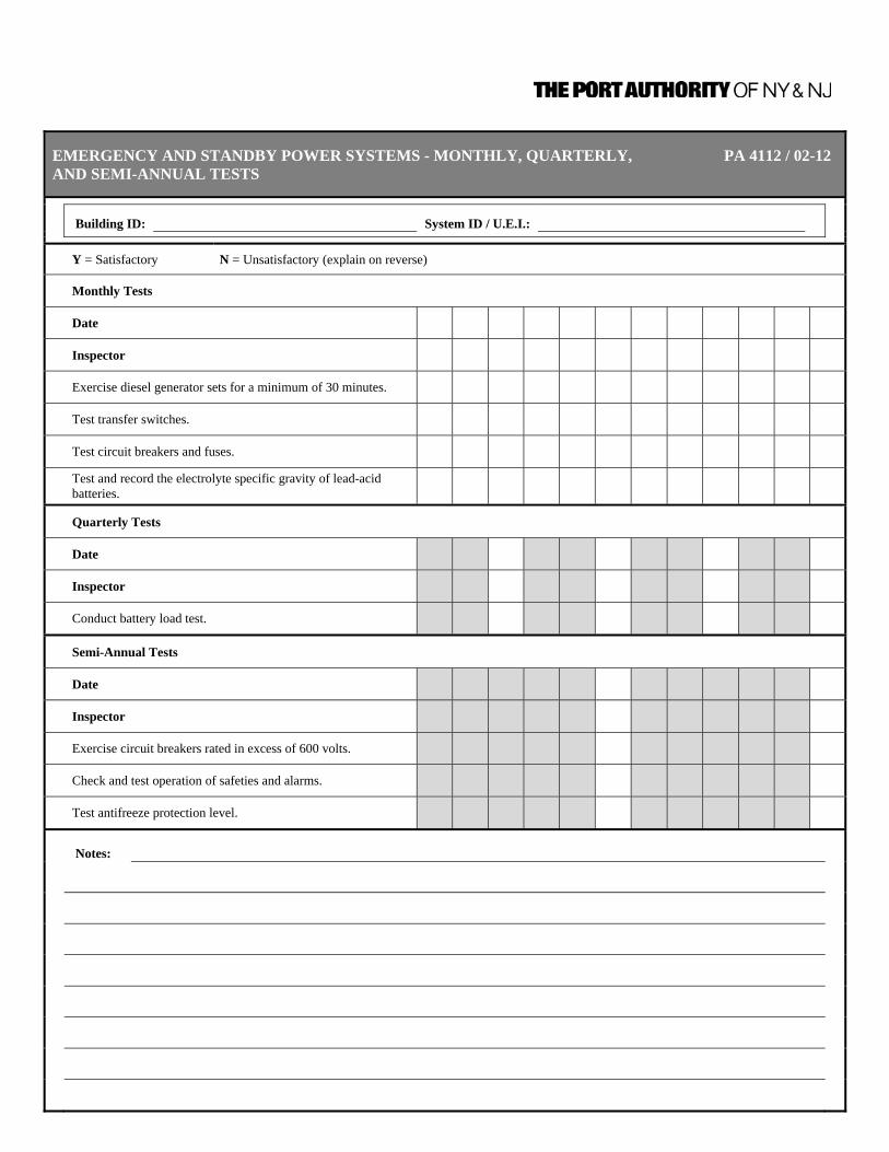
EMERGENCY AND STANDBY POWER SYSTEMS - MONTHLY, QUARTERLY, PA 4112 / 02-12 AND SEMI-ANNUAL TESTS
Building ID: System ID / U.E.I.:
Y = Satisfactory N = Unsatisfactory (explain on reverse)
Monthly Tests
Date
Inspector
Exercise diesel generator sets for a minimum of 30 minutes.
Test transfer switches.
Test circuit breakers and fuses.
Test and record the electrolyte specific gravity of lead-acid batteries.
Quarterly Tests
Date
Inspector
Conduct battery load test.
Semi-Annual Tests
Date
Inspector
Exercise circuit breakers rated in excess of 600 volts.
Check and test operation of safeties and alarms.
Test antifreeze protection level.
Notes:
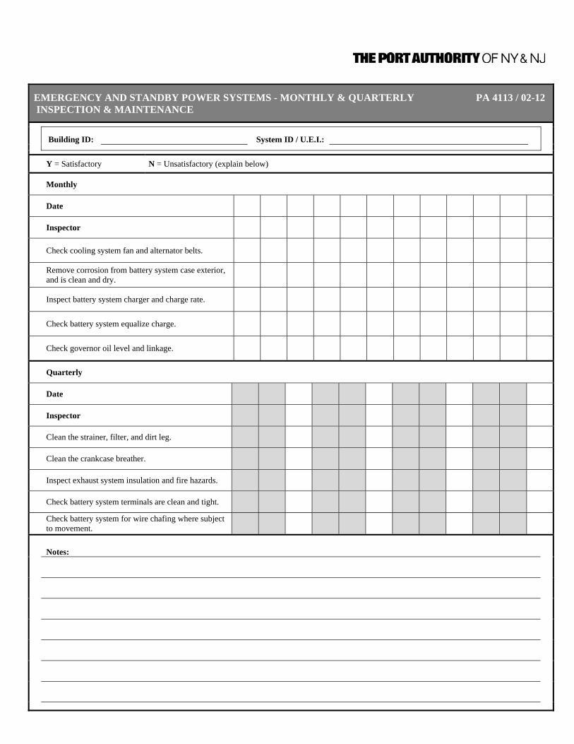
EMERGENCY AND STANDBY POWER SYSTEMS - MONTHLY & QUARTERLY PA 4113 / 02-12 INSPECTION & MAINTENANCE
Building ID: System ID / U.E.I.:
Y = Satisfactory N = Unsatisfactory (explain below)
Monthly
Date
Inspector
Check cooling system fan and alternator belts.
Remove corrosion from battery system case exterior, and is clean and dry.
Inspect battery system charger and charge rate.
Check battery system equalize charge.
Check governor oil level and linkage.
Quarterly
Date
Inspector
Clean the strainer, filter, and dirt leg.
Clean the crankcase breather.
Inspect exhaust system insulation and fire hazards.
Check battery system terminals are clean and tight.
Check battery system for wire chafing where subject to movement.
Notes:
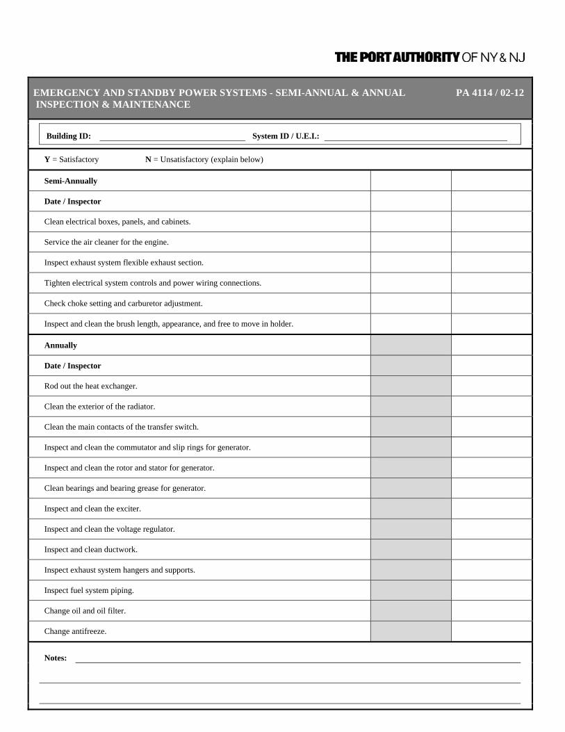
EMERGENCY AND STANDBY POWER SYSTEMS - SEMI-ANNUAL & ANNUAL PA 4114 / 02-12 INSPECTION & MAINTENANCE
Building ID: System ID / U.E.I.:
Y = Satisfactory N = Unsatisfactory (explain below)
Semi-Annually
Date / Inspector
Clean electrical boxes, panels, and cabinets.
Service the air cleaner for the engine.
Inspect exhaust system flexible exhaust section.
Tighten electrical system controls and power wiring connections.
Check choke setting and carburetor adjustment.
Inspect and clean the brush length, appearance, and free to move in holder.
Annually
Date / Inspector
Rod out the heat exchanger.
Clean the exterior of the radiator.
Clean the main contacts of the transfer switch.
Inspect and clean the commutator and slip rings for generator.
Inspect and clean the rotor and stator for generator.
Clean bearings and bearing grease for generator.
Inspect and clean the exciter.
Inspect and clean the voltage regulator.
Inspect and clean ductwork.
Inspect exhaust system hangers and supports.
Inspect fuel system piping.
Change oil and oil filter.
Change antifreeze.
Notes:

EMERGENCY AND STANDBY POWER SYSTEMS - 1, 2, 3 AND 5-YEAR TESTS PA 4115 / 02-12
Building ID: System ID / U.E.I.:
Y = Satisfactory N = Unsatisfactory (explain below)
1-Year 2-Year 3-Year 4-Year 5-Year
Date:
Inspector:
Ann
ual
Exercise diesel generator sets for a total of 2 continuous hours.
Exercise EPSS circuit breakers including main and feed breakers between the EPS and the transfer switch load terminals.
Test fuel quality.
Test louver motor and controls.
Test fuel tank vents and overflow pipe for blockage.
Test exhaust system for excessive back pressure.
Test calibration of voltage-sensing relays/devices.
Check, clean, and test ignition system - plugs, points, coil, cap, rotor, secondary wire insulation.
Test injector pump and injectors for flow rate, pressure, and/or spray pattern.
Measure and record resistance readings of windings with insulation tester.
2-Y
r Test circuit breakers rated in excess of 600 volts under simulated overload conditions.
3-Y
ear
Test EPSS for 4 hours for the duration of its class.
Test valve clearance.
Test torque bolts.
5-Y
r
Test electrical system wire insulation breakdown.
Notes:

EMERGENCY AND STANDBY POWER SYSTEMS - PA 4116 / 02-12 STORED ELECTRICAL ENERGY EMERGENCY & STANDBY POWER SYSTEMS - MONTHLY, QUARTERLY, & ANNUALLY - INSPECTION & TEST
Building ID: System ID / U.E.I.:
Y = Satisfactory N = Unsatisfactory (explain on reverse)
Monthly Inspection
Date
Inspector
Check the battery and associated charger/control equipment.
Check battery electrolyte levels and refilled as necessary.
Clean and regrease terminals and intercell connectors, and cell tops.
Check individual cell voltages and recorded where practical.
Check and record the specific gravity of pilot cells, where applicable.
Inspect the conditions of the plates and sediment of free electrolyte, lead–acid batteries in transparent containers.
Check all indicator lamps, meters, and controls to verify that they are operating correctly.
Check the load value to ensure that it is within the equipment rating.
Quarterly Test
Date
Inspector
Exercise equipment under connected load for a minimum of 5 minutes.
Record the following at the beginning and end of test: Output voltage
Battery voltage
Duration of test
Annual Test
Date
Inspector
Check the SEPSS at full load for the duration of its class.
Notes:

Inspection, Testing, and Maintenance Requirements for Fire Protection and Life Safety Systems
CHAPTER 13 – MEANS OF EGRESS 9/30/2011 | Page 13-1
CHAPTER 13 – MEANS OF EGRESS
GENERAL INFORMATION
Emergency generators providing power to emergency lighting systems shall be inspected, tested, and maintained in accordance with Chapter 12 of this Manual and NFPA 110, Standard for Emergency and Standby Power Systems. Stored electrical energy systems shall be inspected, tested, and maintained in accordance with Chapter 12 of this Manual and NFPA 111, Standard on Stored Electrical Energy Emergency and Standby Power Systems. Battery-operated emergency lights shall use only reliable types of rechargeable batteries provided with suitable facilities for maintaining them in properly charged condition.
For the purposes of this Chapter, the information provided for inspection, testing, and maintenance are for equipment and systems that are not self-testing and/or self diagnostic battery operated units. Inspection, testing, and maintenance requirements for self-testing/self-diagnostic battery-operated emergency lighting and exit signs must be available for individual review.
DEFINITIONS Means of Egress System Components Exit Access That portion of a means of egress system that leads from
any occupied portion of a building or structure to an exit. Exit That portion of a means of egress system, which is
separated from other interior spaces of a building or structure by fire-resistance-rated construction and opening protective as required to provide a protected path of egress travel between the exit access and the exit discharge. Exits include vertical exits, exterior exit doors at ground level, exit enclosures, exit passageways, exterior exit stairs, exterior exit ramps and horizontal exits, but do not include access stairs, aisles, exit access doors opening to corridors or corridors.
Exit Discharge That portion of a means of egress system between the
termination of an exit and a public way.

Inspection, Testing, and Maintenance Requirements for Fire Protection and Life Safety Systems
CHAPTER 13 – MEANS OF EGRESS 9/30/2011 | Page 13-2
GENERAL REQUIREMENTS FOR MEANS OF EGRESS
1028.1 An exit shall not be utilized for any purpose that interferes with its function as a means of egress, except as otherwise approved. The means of egress from each part of the structure, including exits, stairways, egress doors and any panic hardware installed thereon, aisles, corridors, passageways and similar elements of the means of egress, shall at all times be maintained in a safe condition and available for immediate utilization and free of all obstructions. Security devices affecting means of egress shall be subject to approval.
1028.1.1 Storage. Combustible or flammable material shall not be placed, stored or
kept in any portion of an exit, elevator car or hoistway, or at the bottom of a stairway, fire escape or other means of escape, unless such space is enclosed and protected as required by the construction code in effect at the time of first occupancy. Such storage shall be located so the presence or burning of the materials will not obstruct or render hazardous the means of egress.
1028.3 Reliability. Required exit accesses, exits or exit discharges shall be
continuously maintained free from obstructions or impediments to full instant use in the case of fire or other emergency when the areas served by such exits are occupied. Security devices affecting means of egress shall be subject to approval of the fire code official.
1028.4 Continued maintenance. All means of egress devices and safeguards that
are required by this chapter or which were required by a previous statute or another code when the structure was erected, altered or repaired, shall be maintained in good working order.
1028.5 Obstructions. A means of egress shall be free from obstructions that would
prevent its use, including the accumulation of snow and ice.
1028.6 Exterior egress. All exit discharge, exterior stairways and fire escapes shall be kept free of snow and ice. Any fire escape or exterior stairway found to be in a state of deterioration or determined to be unsafe shall be repaired immediately. Depending upon the structural condition, a load test of any fire escape shall be conducted before the escape is returned to service.
1028.7 Exit signs. Decorations, furnishings, equipment or adjacent signage that
impairs the visibility of exit signs, creates confusion or prevents identification of the exit shall not be allowed.
1028.8 Furnishings and decorations. Furnishings, decorations or other objects shall
not be placed so as to obstruct exits, access thereto, egress therefrom, or visibility thereof. Hangings and draperies shall not be placed over exit doors or otherwise be located to conceal or obstruct an exit. Mirrors shall not be placed on exit doors. Mirrors shall not be placed in or adjacent to any exit in such a manner as to confuse the direction of exit.
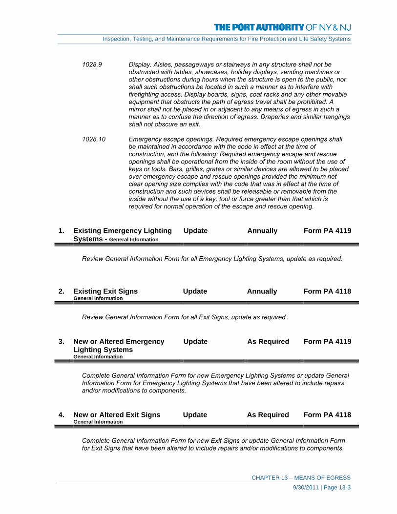
Inspection, Testing, and Maintenance Requirements for Fire Protection and Life Safety Systems
CHAPTER 13 – MEANS OF EGRESS 9/30/2011 | Page 13-3
1028.9 Display. Aisles, passageways or stairways in any structure shall not be
obstructed with tables, showcases, holiday displays, vending machines or other obstructions during hours when the structure is open to the public, nor shall such obstructions be located in such a manner as to interfere with firefighting access. Display boards, signs, coat racks and any other movable equipment that obstructs the path of egress travel shall be prohibited. A mirror shall not be placed in or adjacent to any means of egress in such a manner as to confuse the direction of egress. Draperies and similar hangings shall not obscure an exit.
1028.10 Emergency escape openings. Required emergency escape openings shall
be maintained in accordance with the code in effect at the time of construction, and the following: Required emergency escape and rescue openings shall be operational from the inside of the room without the use of keys or tools. Bars, grilles, grates or similar devices are allowed to be placed over emergency escape and rescue openings provided the minimum net clear opening size complies with the code that was in effect at the time of construction and such devices shall be releasable or removable from the inside without the use of a key, tool or force greater than that which is required for normal operation of the escape and rescue opening.
1. Existing Emergency Lighting
Systems - General Information Update Annually Form PA 4119
Review General Information Form for all Emergency Lighting Systems, update as required.
2. Existing Exit Signs
General Information Update Annually Form PA 4118
Review General Information Form for all Exit Signs, update as required.
3. New or Altered Emergency
Lighting Systems General Information
Update As Required Form PA 4119
Complete General Information Form for new Emergency Lighting Systems or update General Information Form for Emergency Lighting Systems that have been altered to include repairs and/or modifications to components.
4. New or Altered Exit Signs
General Information Update As Required Form PA 4118
Complete General Information Form for new Exit Signs or update General Information Form for Exit Signs that have been altered to include repairs and/or modifications to components.
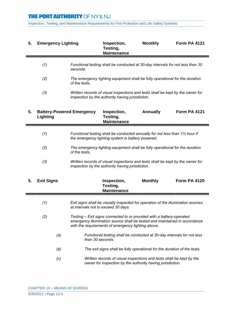
Inspection, Testing, and Maintenance Requirements for Fire Protection and Life Safety Systems
CHAPTER 13 – MEANS OF EGRESS 9/30/2011 | Page 13-4
5. Emergency Lighting Inspection, Testing, Maintenance
Monthly Form PA 4121
(1) Functional testing shall be conducted at 30-day intervals for not less than 30
seconds.
(2) The emergency lighting equipment shall be fully operational for the duration of the tests.
(3) Written records of visual inspections and tests shall be kept by the owner for
inspection by the authority having jurisdiction. 5. Battery-Powered Emergency
Lighting Inspection, Testing, Maintenance
Annually Form PA 4121
(1) Functional testing shall be conducted annually for not less than 11⁄2 hour if
the emergency lighting system is battery powered.
(2) The emergency lighting equipment shall be fully operational for the duration of the tests.
(3) Written records of visual inspections and tests shall be kept by the owner for
inspection by the authority having jurisdiction. 5. Exit Signs Inspection,
Testing, Maintenance
Monthly Form PA 4120
(1) Exit signs shall be visually inspected for operation of the illumination sources
at intervals not to exceed 30 days.
(2) Testing – Exit signs connected to or provided with a battery-operated emergency illumination source shall be tested and maintained in accordance with the requirements of emergency lighting above.
(a) Functional testing shall be conducted at 30-day intervals for not less
than 30 seconds.
(b) The exit signs shall be fully operational for the duration of the tests.
(c) Written records of visual inspections and tests shall be kept by the owner for inspection by the authority having jurisdiction.

Inspection, Testing, and Maintenance Requirements for Fire Protection and Life Safety Systems
CHAPTER 13 – MEANS OF EGRESS 9/30/2011 | Page 13-5
5. Battery-Powered Exit Signs Inspection,
Testing, Maintenance
Annually Form PA 4120
(1) Testing – Exit signs connected to or provided with a battery-operated emergency illumination source shall be tested and maintained in accordance with the requirements of emergency lighting above.
(a) Functional testing shall be conducted annually for not less than 11⁄2
hour.
(b) The exit signs shall be fully operational for the duration of the tests.
(c) Written records of visual inspections and tests shall be kept by the owner for inspection by the authority having jurisdiction.

MEANS OF EGRESS - GENERAL INFORMATION - EXIT SIGNS PA 4118 / 02-12
Building ID: Total Number of Exit Signs:
1.
Exit Sign Identification - Provide unique identifier for each Exit Sign. Do not include Exit Door Tactile Signs. Do include illuminated Floor Proximity Exit Signs
2.
Provide location of Exit Sign
3.
Identify Type of Exit Sign - Internally/Externally Illuminated, Photoluminiscent, Phosphorescent, etc. Also indicate if sign is a directional sign with indicating arrow.
4.
Provide any other information in Notes. Use reverse side of form if necessary.
Sign ID U.E.I. Location Type of Sign Notes
PAGE ____ OF ____

MEANS OF EGRESS - GENERAL INFORMATION - EMERGENCY LIGHTING PA 4119 / 02-12
Building ID: Total Number of Emergency Lighting Systems:
1. Emergency Lighting System - Provide unique identifier for each System. Stand-alone Battery Backup Lights should be individually identified.
2. Identify location(s) where Emergency Lighting is provided. 3. Identify Number and Type of fixtures in each System. 4. Identify Emergency Power Source for Emergency Lighting. If powered through an emergency power circuit, identify the circuit. 5. Provide any other information in Notes. Use reverse side of form if necessary.
Emergency Lighting System ID U.E.I. Location Number & Type of
Fixture(s) Emergency Power Source Notes
PAGE ____ OF ____

MEANS OF EGRESS - EXIT SIGNS - INSPECTION, TESTING, MAINTENANCE RECORD PA 4120 / 02-12
Building ID: Total Number of Exit Signs:
Sign ID U.E.I.
Document (M) for monthly, (A) for Annual Include Date for completed work.
Notes
PAGE ____ OF ____

MEANS OF EGRESS - EMERGENCY LIGHTING - INSPECTION, TESTING, PA 4121 / 02-12MAINTENANCE RECORD
Building ID: Total Number of Emergency Lighting Systems:
Emergency Lighting System ID U.E.I.
Document (M) for monthly, (A) for Annual Include Date for completed work.
Notes
PAGE ____ OF ____

Inspection, Testing, and Maintenance Requirements for Fire Protection and Life Safety Systems
CHAPTER 14 – FIRE DOORS AND OTHER OPENING PROTECTIVES 9/30/2011 | Page 14-1
CHAPTER 14 – FIRE DOORS AND OTHER
OPENING PROTECTIVES
DEFINITIONS Kalamein door A door of composite construction, usually having a wood
core and clad with galvanized sheet metal, sometimes with panels of sheetrock or asbestos.
Automatic-Closing Device. A device that causes the door or window to close when
activated by a fusible link or detector. Automatic-Closing Door. A door that normally is open but that closes when the
automatic-closing device is activated Closed Position (Rolling Steel Fire Door) A position of the door curtain with the underside of the
bottom bar, including a compressible seal or sensing edge, if provided, in contact with the sill along the entire width of the opening.
Closing Device. A means of closing a door from the partially or fully opened
position. Door Closer (Swinging). A labeled device that, where applied to a door and frame,
causes an open door to close by mechanical force. The closing speed can be regulated by this device.
Door Holder/Release Device. A labeled, fail-safe device, controlled by a detection device,
used on an automatic closing door to release the door at the time of fire.
Field Modifications. Changes made to a listed assembly or component after it
has been manufactured. Fire Door. The door component of a fire door assembly. Fire Door Assembly. Any combination of a fire door, a frame, hardware, and other
accessories that together provide a specific degree of fire protection to the opening.
Fire Door Frame. A component forming the perimeter of an opening in a fire
door assembly that is supplied welded or knocked down and anchored to the surrounding structure.
Fire Door Frame for Lights. A frame that, in addition to a door opening, contains an
opening(s) for use with glazing materials. Fire Door Frame for Panels. A frame that, in addition to a door opening, contains an
opening(s) for use with fixed panels of solid metal or wood.

Inspection, Testing, and Maintenance Requirements for Fire Protection and Life Safety Systems
CHAPTER 14 – FIRE DOORS AND OTHER OPENING PROTECTIVES 9/30/2011 | Page 14-2
Fire Door Hardware. Door hardware furnished for swinging and sliding fire doors
by the door manufacturer as a component part of the listed door assembly.
Fire Exit Hardware. Labeled devices for swinging fire doors installed to facilitate
safe egress of persons and generally consisting of a crossbar and various types of latch mechanisms that cannot hold the latch in a retracted locked position.
Fire Protection Glazing. Glazing that has a fire protection rating. Fire Protection Rating. For the purposes of this standard, the designation indicating
the duration of the fire test exposure to which a fire door assembly or fire window assembly was exposed and for which it successfully met all acceptance criteria.
Fire-Rated Damper Mullion. A mullion used to separate multiple listed dampers in large
openings. Fire Resistance Glazing. Glazing that has a fire resistance rating. Fire Resistance Rating. The time, in minutes or hours, that materials or assemblies
have withstood a fire exposure. Fire Shutter. A fire door assembly used for the protection of a window
opening in an exterior wall. Fire Window Assembly. A window or glass block assembly having a fire protection
rating. Automatic Flush Bolts. A mortised bolt installed near the top or bottom of the
inactive leaf of a pair of doors that holds the inactive leaf in a closed position until the active leaf is opened.
Manual Flush Bolts. A mortised bolt installed near the top or bottom of the
inactive leaf of a pair of doors in which the bolts are manually extended or retracted into or out of the header or sill by means of a lever.
Fusible Link. For the purposes of this standard, a listed device consisting
of pieces of metal held together by low-melting-point solder. Breakaway Connection. A joint connecting a fire damper sleeve and attached
ductwork that will allow collapse of the ductwork during a fire without disturbing the integrity of the fire damper.
Combination Fire/Smoke Damper. A device that meets both the fire damper and smoke damper
requirements. Dynamic System. An HVAC system designed to maintain the movement of air
within the system at the indication of a fire.

Inspection, Testing, and Maintenance Requirements for Fire Protection and Life Safety Systems
CHAPTER 14 – FIRE DOORS AND OTHER OPENING PROTECTIVES 9/30/2011 | Page 14-3
Fire Damper. A device installed in an air distribution system, designed to
close automatically upon detection of heat, to interrupt migratory airflow and to restrict the passage of flame. Fire dampers are classified for use in either static systems or for dynamic systems, where the dampers are rated for closure under airflow.
Retaining Angle. The metal angle used to retain the fire damper in the
opening. Smoke Damper. A device within an operating (dynamic) air distribution
system to control the movement of smoke. Static System. An HVAC system designed to stop the movement of air
within the system at the indication of a fire. Volume Control Damper. A fire damper, smoke damper, or combination fire/smoke
damper that is also used to control the volume of air in an HVAC system.
A All Fire Doors and Opening Protectives
1. Existing Fire Doors
General Information Update Annually Form PA 4123
Review General Information Form for all Fire Doors, update as required.
2. New or Altered Fire Doors
General Information Update As Required Form PA 4123
Complete General Information Form for new Fire Doors or update General Information Form for Fire Doors that have been altered to include repairs and/or modifications to components.
3. Existing Opening Protectives
General Information Update Annually Form PA 4124
Review General Information Form for all Opening Protectives, update as required.

Inspection, Testing, and Maintenance Requirements for Fire Protection and Life Safety Systems
CHAPTER 14 – FIRE DOORS AND OTHER OPENING PROTECTIVES 9/30/2011 | Page 14-4
4. New or Altered Opening
Protectives – General Information Update As Required Form PA 4124
Complete General Information Form for new Fire Doors or update General Information Form for Fire Doors that have been altered to include repairs and/or modifications to components.
5. Fire Doors Inspection,
Maintenance Quarterly Form PA 4126
15-2.1.1 Hardware shall be examined frequently and any parts found to be inoperative
shall be replaced immediately.
15-2.1.3 Chains or cables employed on suspended doors shall be inspected frequently for excessive wear and stretching.
15-2.3.1 Door openings and the surrounding areas shall be kept clear of anything that
could obstruct or interfere with the free operation of the door.
15-2.3.2 Where necessary, a barrier shall be built to prevent the piling of material against sliding doors.
15-2.3.3 Blocking or wedging of doors in the open position shall be prohibited.
15-2.4.4 Fusible links or other heat-actuated devices and release devices shall not be
painted.
15-2.4.5 Care shall be taken to prevent paint accumulation on any movable part such as, but not limited to, stay rolls, gears, and closing mechanisms.
15-2.5.1 Broken or damaged glazing material shall be replaced with labeled glazing.
Wire glass shall be well embedded in putty and all exposed joints between the frame and the glass shall be struck and pointed. Other glazing materials shall be installed in accordance with their individual listing.
15-2.5.2 Any breaks in the face covering of doors shall be repaired immediately
15-2.5.3 Where a fire door, frame, or any part of its appurtenances is damaged to the
extent that it could impair the door’s proper emergency function, it shall be repaired with parts obtained from the door’s manufacturer. Upon completion of the repairs, the door shall be tested to ensure emergency operation and closing.
15-2.5.4 When holes are left in a door or frame due to changes or removal of
hardware or plant-ons, the holes shall be repaired by the following methods: (a) Install steel fasteners that adequately fill the holes (b) Fill the screw or bolt holes with the same material as the door or frame
15-2.6.1 Combustible material shall be kept well away from openings.

Inspection, Testing, and Maintenance Requirements for Fire Protection and Life Safety Systems
CHAPTER 14 – FIRE DOORS AND OTHER OPENING PROTECTIVES 9/30/2011 | Page 14-5
6. Fire Doors Testing,
Maintenance Quarterly Form PA 4126
15-2.4.1 Self-closing devices shall be kept in proper working condition at all times.
15-2.4.2 Swinging doors normally held in the open position and equipped with
automatic-closing devices shall be operated at frequent intervals to ensure proper operation.
7. Fire Doors Inspection,
Testing, Maintenance
Annually Form PA 4127
15-2.1.2 Tin clad and Kalamein doors shall be inspected regularly for dry rot.
15-2.2.1 Guides and bearings shall be kept well lubricated to facilitate operation.
15-2.2.2 Chains or cables on biparting, counterbalanced doors shall be checked
frequently and adjustments shall be made to ensure proper latching and to keep the doors in proper relation to the opening.
15-2.4.1 Self-closing devices shall be kept in proper working condition at all times.
15-2.4.3 All horizontal or vertical sliding and rolling fire doors shall be inspected and
tested annually to check for proper operation and full closure. Resetting of the release mechanism shall be done in accordance with the manufacturer’s instructions. A written record shall be maintained and shall be made available to the authority having jurisdiction.
Proper operation shall include all components of the door’s normal functions
including testing of special locking arrangements.
15-2.6.2 Devices that utilize an open flame shall not be used to test fusible links, heat, smoke, or other automatic devices.
8. Opening Protectives Inspection,
Testing, Maintenance
1 Year after Installation
Form PA 4128
19.4.1 Each damper shall be tested and inspected 1 year after.
19.4.2 All tests shall be completed in a safe manner by personnel wearing personal
protective equipment.
19.4.3 Full unobstructed access to the fire or combination fire/ smoke damper shall be verified and corrected as required.

Inspection, Testing, and Maintenance Requirements for Fire Protection and Life Safety Systems
CHAPTER 14 – FIRE DOORS AND OTHER OPENING PROTECTIVES 9/30/2011 | Page 14-6
19.4.4 If the damper is equipped with a fusible link, the link shall be removed for testing to ensure full closure and lock-in-place if so equipped.
6.5.6 The test shall be conducted with normal HVAC airflow.
19.4.5 The operational test of the damper shall verify that there is no damper
interference due to rusted, bent, misaligned, or damaged frame or blades, or defective hinges or other moving parts.
19.4.6 The damper frame shall not be penetrated by any foreign objects that would
affect fire damper operations.
19.4.7 The damper shall not be blocked from closure in any way.
19.4.8 The fusible link shall be reinstalled after testing is complete.
19.4.8.1 If the link is damaged or painted, it shall be replaced with a link of the same size, temperature, and load rating.
19.4.9 All inspections and testing shall be documented, indicating the location of the
fire damper or combination fire/ smoke damper, date of inspection, name of inspector, and deficiencies discovered.
19.4.9.1 The documentation shall have a space to indicate when and how the
deficiencies were corrected.
19.4.11 Periodic inspections and testing of a combination fire/smoke damper shall also meet the inspection and testing requirements contained in Chapter 6 of NFPA 105, Standard for Smoke Door Assemblies and Other Opening Protectives.
9. Opening Protectives Inspection,
Testing, Maintenance
4 Years Thereafter
Form PA 4128
19.4.1.1 The test and inspection frequency shall then be every 4 years, except in
hospitals, where the frequency shall be every 6 years. 10. Opening Protectives Maintenance Annually or
As Needed Form PA 4129
19.5.1 Reports of changes in airflow or noise from the duct system shall be
investigated to verify that they are not related to damper operation.
19.5.2 All exposed moving parts of the damper shall be dry lubricated as required by the manufacturer.
A.19.5.2 Each damper should be examined to ensure that it is not rusted or blocked,
with attention given to hinges and other moving parts.

Inspection, Testing, and Maintenance Requirements for Fire Protection and Life Safety Systems
CHAPTER 14 – FIRE DOORS AND OTHER OPENING PROTECTIVES 9/30/2011 | Page 14-7
19.5.3 If the damper is not operable, repairs shall begin without delay.
19.5.4 Following any repairs, the damper shall be tested for operation. B Aircraft Hangars In addition to A above, the following is required for all Fire Doors in Aircraft Hangar Buildings. 1. Fire Doors Inspection Monthly Form PA 4125
The inspection conducted is for all fire doors in the hangar building in conformance with the following requirements.
15-2.1.1 Hardware shall be examined frequently and any parts found to be inoperative
shall be replaced immediately.
15-2.1.3 Chains or cables employed on suspended doors shall be inspected frequently for excessive wear and stretching.
15-2.3.1 Door openings and the surrounding areas shall be kept clear of anything that
could obstruct or interfere with the free operation of the door.
15-2.3.2 Where necessary, a barrier shall be built to prevent the piling of material against sliding doors.
15-2.3.3 Blocking or wedging of doors in the open position shall be prohibited.
15-2.4.4 Fusible links or other heat-actuated devices and release devices shall not be
painted.
15-2.4.5 Care shall be taken to prevent paint accumulation on any movable part such as, but not limited to, stay rolls, gears, and closing mechanisms.
15-2.5.1 Broken or damaged glazing material shall be replaced with labeled glazing.
Wire glass shall be well embedded in putty and all exposed joints between the frame and the glass shall be struck and pointed. Other glazing materials shall be installed in accordance with their individual listing.
15-2.5.2 Any breaks in the face covering of doors shall be repaired immediately
15-2.5.3 Where a fire door, frame, or any part of its appurtenances is damaged to the
extent that it could impair the door’s proper emergency function, it shall be repaired with parts obtained from the door’s manufacturer. Upon completion of the repairs, the door shall be tested to ensure emergency operation and closing.

Inspection, Testing, and Maintenance Requirements for Fire Protection and Life Safety Systems
CHAPTER 14 – FIRE DOORS AND OTHER OPENING PROTECTIVES 9/30/2011 | Page 14-8
15-2.5.4 When holes are left in a door or frame due to changes or removal of hardware or plant-ons, the holes shall be repaired by the following methods: (a) Install steel fasteners that adequately fill the holes (b) Fill the screw or bolt holes with the same material as the door or frame
15-2.6.1 Combustible material shall be kept well away from openings.

FIRE DOORS AND OTHER OPENING PROTECTIVES - GENERAL INFORMATION - PA 4123 / 02-12FIRE RATED DOORS
Building ID: Total Number of Fire Rated Doors:
1. Door Identification - Provide unique identifier for each Fire Rated Door 2. Provide location of Fire Rated Door 3. Identify Type of Fire Door - Swinging, Rolling, Vertical Sliding, Horizontal Sliding, Fire Shutter, etc 4. Document Fire Rating of Door
5. Provide a list of Other Fire Door Components including Mullions or Astragals, Hold Open Devices, Special Locking arrangements,
Glazing, etc. 6. Provide any other pertinent information in Notes.
Door ID U.E.I. Location Type of Fire Door Fire Rating Other Door Components Notes
PAGE ____ OF ____

FIRE DOORS AND OTHER OPENING PROTECTIVES - PA 4124 / 02-12GENERAL INFORMATION - OPENING PROTECTIVES - FIRE DAMPERS, FIRE/SMOKE DAMPERS, SMOKE DAMPERS
Building ID:
Total Number of Fire Dampers:
Total Number of Fire/Smoke Dampers: Total Number of Smoke Dampers:
1. Damper Identification - Provide unique identifier for each Damper 2. Provide location of Damper 3. Identify Type of Damper - Fire Damper, Fire/Smoke Damper, Smoke Damper 4. Document Fire Rating of Damper (if applicable) 5. Identify if Damper is a component of a Smoke Management System 6. Provide any other pertinent information in Notes.
Damper ID U.E.I. Location Type of Damper Fire Rating Smoke Management
System Notes
PAGE ____ OF ____

FIRE DOORS AND OTHER OPENING PROTECTIVES - AIRCRAFT HANGARS - PA 4125 / 02-12FIRE DOORS - MONTHLY INSPECTION, TESTING, & MAINTENANCE
Date: Building ID: Total Number of Fire Rated Doors:
1. Check door hardware and replace inoperative parts. 2. Check chains or cables on suspended doors for excessive wear and stretching. 3. Check that door openings and surrounding areas are clear not interfering with operation of the door. 4. Check for piling of material against sliding doors. 5. Check that doors are not blocked or wedged in the open position. 6. Check that fusible links or other heat-actuated and release devices are not painted. 7. Check that movable parts such as stay rolls, gears, and closing mechanisms are not painted. 8. Check that glazing material is not broken or damaged and replace with labeled glazing if necessary. 9. Check for any breaks in the face covering of the door and repair if necessary. 10. Check fire door, frame and all appurtenances for damage that would impair operation. 11. Check fire door and frame for holes due to changes or removal of hardware. 12. Test operation of swinging doors normally held open
Y = Satisfactory N = Unsatisfactory (explain on reverse) N/A = Not applicable
Fire Door ID and/or U.E.I. 1 2 3 4 5 6 7 8 9 10 11 12
Notes: Use reverse side for comments.

FIRE DOORS AND OTHER OPENING PROTECTIVES - FIRE DOORS - PA 4126 / 02-12QUARTERLY INSPECTION, TESTING & MAINTENANCE
Date: Building ID: Total Number of Fire Rated Doors:
1. Check door hardware and replace inoperative parts. 2. Check chains or cables on suspended doors for excessive wear and stretching. 3. Check that door openings and surrounding areas are clear not interfering with operation of the door. 4. Check for piling of material against sliding doors. 5. Check that doors are not blocked or wedged in the open position. 6. Check that fusible links or other heat-actuated and release devices are not painted. 7. Check that movable parts such as stay rolls, gears, and closing mechanisms are not painted. 8. Check that glazing material is not broken or damaged and replace with labeled glazing if necessary. 9. Check for any breaks in the face covering of the door and repair if necessary. 10. Check fire door, frame and all appurtenances for damage that would impair operation. 11. Check fire door and frame for holes due to changes or removal of hardware. 12. Test operation of swinging doors normally held open
Y = Satisfactory N = Unsatisfactory (explain on reverse) N/A = Not applicable
Fire Door ID and/or U.E.I. 1 2 3 4 5 6 7 8 9 10 11 12
Notes: Use reverse side for comments.

FIRE DOORS AND OTHER OPENING PROTECTIVES - FIRE DOORS - PA 4127 / 02-12 ANNUAL INSPECTION, TESTING & MAINTENANCE
Date: Building ID: Total Number of Fire Rated Doors:
1. Check Tin Clad and Kalamein doors for dry rot. 2. Lubricate guides and bearings to facilitate operation. 3. Check chains or cables on Biparting and Counterbalanced doors and make adjustments as necessary. 4. Test all self-closing devices for proper operation. 5. Test all horizontal or vertical sliding and rolling doors for proper operation and full closure. 6. Test all special locking arrangements for proper operation.
Y = Satisfactory N = Unsatisfactory (explain on reverse) N/A = Not applicable
Fire Door ID and/or U.E.I. 1 2 3 4 5 6
Notes:

FIRE DOORS AND OTHER OPENING PROTECTIVES - FIRE DAMPER, FIRE/SMOKE PA 4128 / 02-12 DAMPER, SMOKE DAMPER - INSPECTION, TESTING & MAINTENANCE
Building ID: Total Number of Fire Dampers:
Total Number of Fire/Smoke Dampers: Total Number of Smoke Dampers:
1. Check that full unobstructed access is provided to the damper. Correct as required.
2. If the damper is equipped with a fusible link, remove the link for testing to ensure full closure and lock-in-place if so equipped.
3. Check satisfactory damper operation through full range confirming no interference from rusted, bent or blocked damper frame or blades or defective hinges or other moving parts.
4. Check the damper frame for penetrations by foreign objects that would affect operation.
5. Confirm that the fusible link is reinstalled after testing is complete. Replace the link if it is damaged or painted.
6. Check that approved breakaway connections are used to connect the ducts to the frame.
7. Check that springs are not rusted, bent, or twisted.
8. Inspect that the angle iron is properly installed on all four sides and covers the wall opening. Angles do not have to be attached to the wall but should be securely fastened to the damper frame.
9. Lubricate moving parts and clean as necessary.
Date: Y = Satisfactory N = Unsatisfactory (explain on reverse) N/A = Not Applicable
Damper ID and/or U.E.I. // Date of Last ITM 1 2 3 4 5 6 7 8 9
Notes:

FIRE DOORS AND OTHER OPENING PROTECTIVES - FIRE DAMPER, PA 4129 / 02-12 FIRE/SMOKE DAMPER, SMOKE DAMPER - ANNUAL MAINTENANCE
Building ID: Total Number of Fire Dampers:
Total Number of Fire/Smoke Dampers: Total Number of Smoke Dampers:
1. Dry lubricate all moving parts of the damper as identified by the manufacturer.
2. Check the damper for rust or blockage with attention given to hinges and other moving parts.
3. Confirm that the damper appears to be operable. Initiate repairs immediately if damper appears inoperable.
4. Following any repairs, the damper shall be tested for operation
Date: Y = Satisfactory N = Unsatisfactory (explain on reverse) N/A = Not applicable
Damper ID and/or U.E.I. 1 2 3 4 Notes

Inspection, Testing, and Maintenance Requirements for Fire Protection and Life Safety Systems
CHAPTER 15 – SMOKE MANAGEMENT SYSTEMS 9/30/2011 | Page 15-1
CHAPTER 15 – SMOKE MANAGEMENT SYSTEMS
GENERAL INFORMATION
For the purposes of this Chapter, Smoke Management Systems are defined as but not limited to systems identified as smoke control, smoke management, smoke purge, smoke exhaust, and stair pressurization systems. The terminology is used interchangeably throughout the Chapter but is intended to identify systems using mechanical fans producing varying pressures to control, manage, evacuate smoke within a building or space.
DEFINITIONS Smoke-Control System An engineered system that uses mechanical fans to produce
pressure differences across smoke barriers to inhibit smoke movement.
Dedicated Smoke-Control System Smoke-control systems and components that are installed
for the sole purpose of providing smoke control, and upon activation these systems operate specifically to perform the smoke-control function.
Nondedicated Smoke-Control Systems Smoke-control systems and components that share
components with some other system(s), such as the building HVAC system, and upon activation cause the HVAC system to change its mode of operation in order to achieve the smoke-control objectives.
Multiple-Injection Pressurization A type of smoke-control system that has pressurization air System supplied from multiple locations. Pressurized Stairwells A type of smoke-control system in which stair shafts are
mechanically pressurized, with respect to the fire area, with outdoor air to keep smoke from contaminating them during a fire incident.
Single-Injection Pressurization A type of smoke control system that has pressurization air System supplied from only one location. Smoke Exhaust System A mechanical or gravity system intended to move smoke
from the smoke zone to the exterior of the building, including smoke removal, purging, and venting systems, as well as the function of exhaust fans utilized to reduce the pressure in a smoke zone.
Zoned Smoke-Control System A smoke-control system that includes smoke exhaust for the
smoke zone and pressurization for all contiguous smoke-control zones.

Inspection, Testing, and Maintenance Requirements for Fire Protection and Life Safety Systems
CHAPTER 15 – SMOKE MANAGEMENT SYSTEMS 9/30/2011 | Page 15-2
Smoke Management System An engineered system that includes all methods that can be used singly or in combination to modify smoke movement.
A. All Smoke Management Systems
A.8.6 During the life of the building, maintenance is essential to ensure that the smoke-control system will perform its intended function under fire conditions. Proper maintenance of the system should, as a minimum, include the periodic testing of all equipment such as initiating devices, fans, dampers, controls, doors, and windows. The equipment should be maintained in accordance with the manufacturer’s recommendations. (See Recommended Practices for All Air Conditioning and Ventilating Systems below.) Special arrangements might have to be made for the introduction of large quantities of outside air into occupied areas or computer centers when outside temperature and humidity conditions are extreme. Because smoke-control systems override limit controls, such as freezestats, tests should be conducted when outside air conditions will not cause damage to equipment and systems.
8.6.1 The tests in Section 8.6 shall be performed on a periodic basis to determine
that the installed systems continue to operate in accordance with the approved design.
8.6.2 The system shall be tested in accordance with 8.6.4 and 8.6.5 by persons
who are thoroughly knowledgeable in the operation, testing, and maintenance of the smoke-control systems.
1. Existing Smoke
Management Systems Update Annually Form PA 4131
Review General Information Form for all Smoke Management Systems, update as required.
Confirm that operating and maintenance instructions, maintenance manuals, and a full set of drawings are provided as required. Additionally, confirm that staff working on the foam fire suppression systems are trained and knowledgeable.
11.7.1 Operating and maintenance instructions and layouts shall be posted at
control equipment with a second copy on file.
11.7.2 All persons who are expected to inspect, test, maintain, or operate foam-generating apparatus shall be thoroughly trained and training shall be kept current over time.
2. New or Altered Smoke
Management Systems Update Annually Form PA 4131
Complete General Information Form for new Smoke Management Systems or update General Information Form for Smoke Management Systems that have been altered to include repairs and/or modifications to components.

Inspection, Testing, and Maintenance Requirements for Fire Protection and Life Safety Systems
CHAPTER 15 – SMOKE MANAGEMENT SYSTEMS 9/30/2011 | Page 15-3
Confirm that operating and maintenance instructions, maintenance manuals, and a full set of drawings are provided as required. Additionally, confirm that staff working on the foam fire suppression systems are trained and knowledgeable.
11.7.1 Operating and maintenance instructions and layouts shall be posted at
control equipment with a second copy on file.
11.7.2 All persons who are expected to inspect, test, maintain, or operate foam-generating apparatus shall be thoroughly trained and training shall be kept current over time.
3. Dedicated Systems Testing Semi-Annually Form PA 4132
8.6.4.1 Dedicated systems shall be tested at least semiannually.
8.6.4.2 The smoke-control system shall be operated for each control sequence in the current design criteria.
8.6.4.3 Operation of the correct outputs for each given input shall be verified.
8.6.4.4 Where standby power is provided, tests shall also be conducted under
standby power.
4. Non-Dedicated Systems Testing Annually Form PA 4132
8.6.5.1 Nondedicated systems shall be tested at least annually.
8.6.5.2 The smoke-control system shall be operated for each control sequence in the current design criteria.
8.6.5.3 Operation of the correct outputs for each given input shall be verified.
8.6.5.4 If standby power is provided, tests shall also be conducted under standby
power.

Inspection, Testing, and Maintenance Requirements for Fire Protection and Life Safety Systems
CHAPTER 15 – SMOKE MANAGEMENT SYSTEMS 9/30/2011 | Page 15-4
B. Smoke Management Systems in Malls, Atria, and
Large Spaces 1. Smoke Management
Systems Inspection, Testing, Maintenance
Semi-Annually Form PA 4132
8.4.1 Proper maintenance of the system shall, as a minimum, include the periodic
testing of all equipment, such as initiating devices, fans, dampers, controls, doors, and windows.
8.4.2 The equipment shall be maintained in accordance with the manufacturer’s
recommendations. 8.4.3 The periodic test shall determine the airflow quantities and the pressure
differences at the following locations: 1) Across smoke barrier openings 2) At the makeup supplies 3) At the smoke exhaust equipment
8.4.4 All data points shall coincide with the acceptance test location to facilitate comparison measurements.
8.4.5 The system shall be tested at least semiannually by persons who are
thoroughly knowledgeable in the operation, testing, and maintenance of the systems.
8.4.5.1 The results of the tests shall be documented in the operations and
maintenance log and made available for inspection. 8.4.5.2 The smoke management system shall be operated for each sequence in the
current design criteria. 8.4.5.3 The operation of the correct outputs for each given input shall be observed. 8.4.5.4 Tests shall also be conducted under standby power if applicable. 8.4.6 Special arrangements shall be considered for the introduction of larger
quantities of outside air into occupied areas or computer centers when outside temperature and humidity conditions are extreme and when such unconditioned air could damage contents.

Inspection, Testing, and Maintenance Requirements for Fire Protection and Life Safety Systems
CHAPTER 15 – SMOKE MANAGEMENT SYSTEMS 9/30/2011 | Page 15-5
C. Smoke Management Systems for Aircraft
Hangars 1. Ventilation System in Pits,
Tunnels, & Ducts Testing Semi-Annually Form PA 4132
Functional testing is conducted demonstrating satisfactory operation of the system.
D. Recommended Practices for All Air Conditioning
and Ventilating Systems
The following information is provided as guidelines to maintain proper operations of mechanical ventilation systems that are part of smoke management systems. The tasks below are highlighted by NFPA since the continued operation of all components of the ventilation systems are essential to the smoke management system.
B.1.1 Owners should develop a greater awareness of the life and property protection abilities of air-conditioning systems and should establish a planned maintenance schedule. Failure to maintain proper conditions of cleanliness in air duct systems and carelessness in connection with repair operations have been important contributing causes of several fires that have involved air-conditioning systems. The recommendations in this annex apply, in general, to the period of operation of the system; systems operating only part of the year should be given a thorough general checkup before starting operation and again after a shutdown.
B.1.2 The interval of testing and maintenance varies widely depending on the
duration of system operation, condition of fresh air, amount of dust in return air, and other factors. The intervals specified in this standard are intended to be the maximum and should be shortened if system conditions warrant.
B.1.3 The use of an inspection form to obtain a thorough inspection is
recommended. The form should fit the system or systems involved, listing the items needing attention. However, it is recommended that provision be made on the form for equipment location, inspection frequency, due date, inspection date, inspector, and record of discrepancies found.

Inspection, Testing, and Maintenance Requirements for Fire Protection and Life Safety Systems
CHAPTER 15 – SMOKE MANAGEMENT SYSTEMS 9/30/2011 | Page 15-6
1. Filters Inspection,
Maintenance Per Manufacturer’s Requirements
Form PA 4133
Replace or clean filters when resistance to airflow increases to no more than two times the original resistance or reaches manufacturer’s recommended value for replacement. B.3.1 All air filters should be kept free of excess dust and combustible material.
Unit filters should be renewed or cleaned when the resistance to airflow has increased to two times the original resistance or when the resistance has reached a value of recommended replacement by the manufacturer. A suitable draft gauge should be provided for the purpose. Where the filters are of the automatic liquid adhesive type, sludge should be removed from the liquid adhesive reservoir regularly.
B.3.2 When replacing filters, care should be taken to use the proper type and size
and to avoid gaps. B.3.3 Filters designed and manufactured to be thrown away after use should never
be cleaned and reused. 2. Electrical Equipment of
Automatic Filters Inspection, Testing, Maintenance
Semi-Annually Form PA 4133
Check Motors & Relays B.3.5 Electrical equipment of automatic filters should be inspected semiannually,
observing the operation cycle to ensure that the motor, relays, and other controls function as intended. Drive motors and gear reductions also should be inspected at least semiannually and lubricated when necessary.
3. Fans and Fan Motors Inspection,
Testing, Maintenance
Quarterly Form PA 4133
B.8.1 Fans and fan motors should be inspected at least quarterly and cleaned and
lubricated when necessary. Care should be exercised in lubricating fans to avoid allowing lubricant to run onto the fan blades. Fans also should be checked for alignment and checked to see that they are running freely.
B.8.2 The alignment of fan belt drives should be checked, because improper
alignment can cause motor overheating as well as premature belt failure.

Inspection, Testing, and Maintenance Requirements for Fire Protection and Life Safety Systems
CHAPTER 15 – SMOKE MANAGEMENT SYSTEMS 9/30/2011 | Page 15-7
4. Fan Controls Inspection,
Testing, Maintenance
Annually Form PA 4133
B.9 Fan controls should be examined and activated at least annually to ensure
that they are in operable condition. 5. Inspection and Cleaning of
Ducts Inspection, Maintenance
Quarterly or As Required
Form PA 4133
B.4.1 Inspections to determine the amount of dust and waste material in the ducts
(both discharge and return) should be made quarterly. However, if, after several inspections, such frequent inspection is determined to be unnecessary, the interval between inspections can be permitted to be adjusted to suit the conditions.
B.4.3 Cooling and heating coils should be cleaned, if necessary, at the time ducts
are cleaned. Thorough cleaning of ducts can require scraping, brushing, or other positive means. Vacuum cleaning might not remove dust of an oily or sticky nature or heavy accumulations in the elbows or seams. The amount and kind of dust and dirt depend greatly on the occupancy and the arrangement of the duct system. Additional access doors or panels could be needed for a complete cleaning of duct systems.
6. Inspection and Cleaning of Plenums
Inspection, Maintenance
Monthly or As Required
Form PA 4133
B.5.1 Apparatus casing and air-handling unit plenums should be inspected
monthly. However, if, after several inspections, such frequent inspection is determined to be unnecessary, the interval between inspections can be adjusted to suit the conditions.
B.5.3 Cleaning should be undertaken whenever an inspection indicates the need,
especially in common plenums serving more than one fan or system. Where plenum chambers being used for storage exist, arrangements, such as keeping the doors locked, should be made to prevent such usage.
7. Inspection and Cleaning of Plenums
Inspection, Maintenance
Quarterly or As Required
Form PA 4133
B.5.2 Ceiling cavity, raised floor, and duct distribution plenums should be inspected
in a manner similar to that of ducts, beginning with quarterly inspections and adjusting the frequency to suit dirt buildup conditions.

Inspection, Testing, and Maintenance Requirements for Fire Protection and Life Safety Systems
CHAPTER 15 – SMOKE MANAGEMENT SYSTEMS 9/30/2011 | Page 15-8
8. Outside Air Intakes Inspection,
Maintenance Quarterly or As Required
Form PA 4133
B.7.1 Conditions outside the outside air intake should be examined at the time
ducts are inspected. Items to be noted include the following: 1) Accumulations of combustible material near the intake. 2) The presence of buildings or structures that could present an exposure
to the intake, allowing smoke and fire to be drawn in. 3) The operating condition of any automatic damper designed to protect the
opening against exposure fire.
B.7.2 Where accumulations of combustible material are noted, they should be
removed immediately and arrangements made to avoid such accumulations. Inspections should thereafter be made more frequently. If newly erected exposures are noticed, consideration should be given to the protection at the intake to ensure that it is adequate. (See 4.3.7.)

SMOKE MANAGEMENT SYSTEMS - GENERAL INFORMATION PA 4131 / 02-12
Original Installation Date: U.E.I. (Unique Element Identification) :
Building ID: System ID / U.E.I.:
Date: Inspector:
Dedicated or Non-Dedicated Smoke Management System:
General
Describe Smoke Management System including start of system, zones, pressurized stairs, etc.
Location of Smoke Management System control panel(s)
Location of operating and maintenance instructions, maintenance manuals, and full set of drawings
Operating Instructions Posted Yes No
Mechanical Equipment Number and Identification of Fans, HVAC equipment
Dampers Number of Dampers in Smoke Management System
Refer to Form 14-PA 4124 For identification of dampers. List all dampers in the smoke management system.
Operating Staff Names of Staff Trained to Operate System Dates of Training
Notes:

SMOKE MANAGEMENT SYSTEMS - INSPECTION AND TEST PA 4132 / 02-12
Building ID: System ID / U.E.I.:
Date: Inspector:
Y = Satisfactory N = Unsatisfactory (explain below) N/A = Not applicable
Record Information Notes
Assure the system is in normal mode.
Test system - normal power.
Test system - emergency power.
Confirm that for each input there is a designated output.
Demonstrate complete smoke management system sequence
Normal mode
Automatic smoke-control from 1st alarm
Manual override of normal and automatic modes
Return to normal
Confirm that the fire alarm inputs produce the correct outputs.
Establish a consistent method for recording pressure differences.
Confirm that the introduction of untempered air will not damage equipment.
Confirm that weather conditions (freezing temperatures) will not damage equipment.
Malls, Atria, Large Spaces
Testing for airflow quantities and the pressure differences at:
Across smoke barrier openings
At the makeup supplies
At the smoke exhaust equipment Aircraft Hangars
Ventilation System in Pits, Tunnels, & Ducts
Notes:
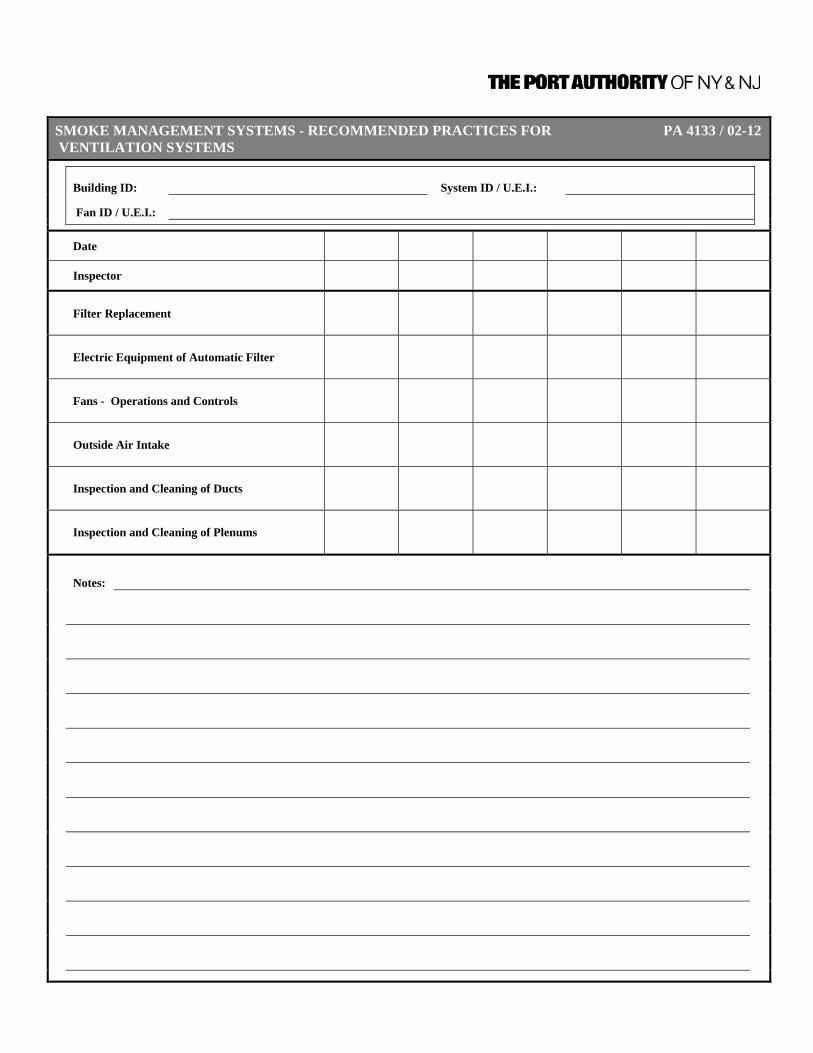
SMOKE MANAGEMENT SYSTEMS - RECOMMENDED PRACTICES FOR PA 4133 / 02-12 VENTILATION SYSTEMS
Building ID: System ID / U.E.I.:
Fan ID / U.E.I.:
Date
Inspector
Filter Replacement
Electric Equipment of Automatic Filter
Fans - Operations and Controls
Outside Air Intake
Inspection and Cleaning of Ducts
Inspection and Cleaning of Plenums
Notes:
Inspection, Testing, and Maintenance Requirements for Fire Protection and Life Safety Systems
CHAPTER 16 – PORTABLE FIRE EXTINGUISHERS 9/30/2011 | Page 16-1
CHAPTER 16 – PORTABLE FIRE EXTINGUISHERS
GENERAL INFORMATION
For the purposes of this Chapter, the requirements identified are for commercial grade portable fire extinguishers and not residential portable fire extinguishers. Additionally, the requirements for high pressure portable fire extinguishers are not included in this Manual.
Documentation for inspection, testing, and maintenance of portable fire extinguishers is identified by NFPA as:
Records shall be kept on a tag or label attached to the fire extinguisher, on an inspection checklist maintained on file or by an electronic method that provides a permanent record.
Due to the potential for movement, documentation is normally kept with the extinguisher. For the purposes of this chapter, a choice is available to maintain documentation with tags and/or labels on the portable extinguisher or to use the forms included at the end of this chapter or an acceptable method of electronic documentation. The owner/tenant responsible for maintenance of fire protection systems and equipment must confirm that the method of documentation used is compliant with the information in this Chapter. Tags and/or labels, if used, must capture all required information. The PA Forms in this Chapter are the recommended option in lieu of tags or labels on the extinguishers. Lastly, electronic documentation will be reviewed and any deficiencies identified must be addressed immediately.
DEFINITIONS Cartridge/Cylinder-Operated Fire A fire extinguisher in which the expellant gas is in a separate Extinguisher container from the agent storage container. Class A Fires. Fires in ordinary combustible materials, such as wood, cloth,
paper, rubber, and many plastics. Class B Fires. Fires in flammable liquids, combustible liquids, petroleum
greases, tars, oils, oil-based paints, solvents, lacquers, alcohols, and flammable gases.
Class C Fires. Fires that involve energized electrical equipment. Class D Fires. Fires in combustible metals, such as magnesium, titanium,
zirconium, sodium, lithium, and potassium.

Inspection, Testing, and Maintenance Requirements for Fire Protection and Life Safety Systems
CHAPTER 16 – PORTABLE FIRE EXTINGUISHERS 9/30/2011 | Page 16-2
Class K Fires. Fires in cooking appliances that involve combustible cooking
media (vegetable or animal oils and fats). Dry Chemical. A mixture of finely divided solid particles, usually sodium
bicarbonate-, potassium bicarbonate-, or ammonium phosphate–based with added particulate material supplemented by special treatment to provide resistance to packing, and moisture absorption (caking), and to promote proper flow characteristics.
Dry Powder. Solid materials in powder or granular form designed to
extinguish Class D combustible metal fires by crusting, smothering, or heat-transferring means.
Electronic Monitoring. A method of electronic communication (data transmission)
between an in-place fire extinguisher and an electronic monitoring device/system.
Extinguisher Inspection. A “quick check” that a fire extinguisher is available and is in
operating condition. It is intended to give reasonable assurance that the fire extinguisher is fully charged. This is done by verifying that it is in its designated place, that it has not been actuated or tampered with, and that there is no obvious physical damage or condition to prevent its operation.
Extinguisher Service Pressure. The normal operating pressure as indicated on the
nameplate or cylinder of a fire extinguisher. Factory Test Pressure. The pressure at which a shell was tested at time of
manufacture. This pressure is shown on the nameplate. Film-Forming Foam Agents. The film-forming foam agents referenced in this standard are
AFFF (aqueous filmforming foam) and FFFP (film-forming fluoroprotein foam).
Halocarbons. Halocarbon agents include hydrochlorofluorocarbon (HCFC),
hydrofluorocarbon (HFC), perfluorocarbon (PFC), and fluoroiodocarbon (FIC) types of agents.
Halons. Halons include bromochlorodifluoromethane (Halon 1211),
bromotrifluoromethane (Halon 1301), and mixtures of Halon 1211 and Halon 1301 (Halon 1211/1301).
High-Pressure Cylinder. For the purposes of this standard, high-pressure cylinders
(and cartridges) are those containing nitrogen, compressed air, carbon dioxide, or other gases at a pressure higher than 500 psi (3447 kPa) at 70°F (21°C).
Hydrostatic Testing. Pressure testing of the extinguisher to verify its strength
against unwanted rupture. Loaded Stream Charge. A water-based extinguishing medium that uses an alkali
metal salt as a freezing point depressant.
Inspection, Testing, and Maintenance Requirements for Fire Protection and Life Safety Systems
CHAPTER 16 – PORTABLE FIRE EXTINGUISHERS 9/30/2011 | Page 16-3
Low-Pressure Cylinder. For the purposes of this standard, low-pressure cylinders are
those containing fire extinguishing agent (medium), nitrogen, compressed air, or other compressed gases at a service pressure of 500 psi (3447 kPa) or lower at 70°F (21°C).
Maintenance. A thorough examination of the fire extinguisher. It is intended
to give maximum assurance that a fire extinguisher will operate effectively and safely. It includes a thorough examination for physical damage or condition to prevent its operation and any necessary repair or replacement. It will normally reveal if hydrostatic testing or internal maintenance is required.
Mild Steel Shell. All steel shells other than stainless steel and steel shells
used for high-pressure cylinders. Nonrechargeable Fire Extinguisher. A nonrechargeable (nonrefillable) fire extinguisher is not
capable of (nor intended to be capable of) undergoing complete maintenance, hydrostatic testing, and being restored to its full operating capability by the standard practices used by fire equipment dealers and distributors.
Portable Fire Extinguisher. A portable device, carried or on wheels and operated by
hand, containing an extinguishing agent that can be expelled under pressure for the purpose of suppressing or extinguishing fire.
Rechargeable (Refillable) Fire A rechargeable (refillable) fire extinguisher is capable of Extinguisher. undergoing complete maintenance, including internal
inspection of the pressure vessel, replacement of all substandard parts and seals, and hydrostatic testing.
Recharging. The replacement of the extinguishing agent (also includes
the expellant for certain types of fire extinguishers). Self-Expelling Fire Extinguisher. A fire extinguisher in which the agents have sufficient vapor
pressure at normal operating temperatures to expel themselves.
Servicing. Includes one or more of the following: (a) maintenance, (b)
recharging, (c) hydrostatic testing. Stored-Pressure Fire Extinguisher. A fire extinguisher in which both the extinguishing material
and expellant gas are kept in a single container, and that includes a pressure indicator or gauge.
Travel Distance. The actual walking distance from any point to the nearest fire
extinguisher fulfilling hazard requirements.

Inspection, Testing, and Maintenance Requirements for Fire Protection and Life Safety Systems
CHAPTER 16 – PORTABLE FIRE EXTINGUISHERS 9/30/2011 | Page 16-4
Water Mist Fire Extinguisher. A water-type portable fire extinguisher containing distilled water and employing a nozzle that discharges the agent in a fine spray.
Water-Type Fire Extinguisher. A water-type fire extinguisher contains water-based agents,
such as water, AFFF, FFFP, antifreeze, and loaded stream. Wet Chemical. Wet chemicals include, but are not limited to, solutions of
water and potassium acetate, potassium carbonate, potassium citrate, or any combinations thereof.
Wetting Agent. A surface-active material added to water to materially reduce
the surface tension of the water and thus increase penetrating and spreading characteristics.
Wheeled Fire Extinguisher. A portable fire extinguisher equipped with a carriage and
wheels intended to be transported to the fire by one person. 49 CFR 180.209(b) Requirements for requalification of specification cylinders. DOT 3A or 3AA cylinders (1) A cylinder conforming to specification DOT 3A or 3AA
with a water capacity of 56.7 kg (125 lb) or less that is removed from any cluster, bank, group, rack, or vehicle each time it is filled, may be requalified every ten years instead of every five years, provided the cylinder conforms to all of the following conditions:
(i) The cylinder was manufactured after December 31, 1945. (ii) The cylinder is used exclusively for air; argon;
cyclopropane; ethylene; helium; hydrogen; krypton; neon; nitrogen; nitrous oxide; oxygen; sulfur hexafluoride; xenon; chlorinated hydrocarbons, fluorinated hydrocarbons, liquefied hydrocarbons, and mixtures thereof that are commercially free from corroding components; permitted mixtures of these gases (see § 173.301(d) of this subchapter); and permitted mixtures of these gases with up to 30 percent by volume of carbon dioxide, provided the gas has a dew point at or below minus (52 °F) at 1 atmosphere.
(iii) Before each refill, the cylinder is removed from any
cluster, bank, group, rack or vehicle and passes the hammer test specified in CGA Pamphlet C–6 (IBR, see § 171.7 of this subchapter).
(iv) The cylinder is dried immediately after hydrostatic testing
to remove all traces of water. (v) The cylinder is not used for underwater breathing.

Inspection, Testing, and Maintenance Requirements for Fire Protection and Life Safety Systems
CHAPTER 16 – PORTABLE FIRE EXTINGUISHERS 9/30/2011 | Page 16-5
(vi) Each cylinder is stamped with a five-pointed star at least one-fourth of an inch high immediately following the test date.
(2) If, since the last required requalification, a cylinder has
not been used exclusively for the gases specifically identified in paragraph (b)(1)(ii) of this section, but currently conforms with all other provisions of paragraph (b)(1) of this section, it may be requalified every 10 years instead of every five years, provided it is first requalified and examined as prescribed by § 173.302a(b) (2), (3) and (4) of this subchapter.
(3) Except as specified in paragraph (b)(2) of this section, if
a cylinder, marked with a star, is filled with a compressed gas other than as specified in paragraph (b)(1)(ii) of this section, the star following the most recent test date must be obliterated. The cylinder must be requalified five years from the marked test date, or prior to the first filling with a compressed gas, if the required five-year requalification period has passed.

Inspection, Testing, and Maintenance Requirements for Fire Protection and Life Safety Systems
CHAPTER 16 – PORTABLE FIRE EXTINGUISHERS 9/30/2011 | Page 16-6
A. All Portable Fire Extinguishers 1. Existing Portable Fire
Extinguishers General Information Update Annually Form PA 4135
Review General Information Form for all Portable Fire Extinguishers, update as required.
2. New or Altered Portable Fire
Extinguishers General Information Update As Required Form PA 4135
Complete General Information Form for new Portable Fire Extinguishers or update General Information Form for Portable Fire Extinguishers that has been altered to include repairs and/or modifications to components.
3. Portable Fire Extinguishers Inspection Monthly Tag or Label on
Extinguisher or Form PA 4136
7.2.1.1 Fire extinguishers shall be manually inspected when initially placed in
service.
7.2.1.2 Fire extinguishers shall be inspected either manually or by means of an electronic monitoring device/system at a minimum of 30-day intervals.
7.2.1.2.1 Where electronic monitoring is used and the specific extinguisher cannot be
verified electronically, the extinguisher shall be continuously monitored for location.
7.2.1.3 Fire extinguishers shall be inspected at more frequent intervals when
circumstances require.
7.2.2 Procedures. Periodic inspection or electronic monitoring of fire extinguishers shall include a check of at least the following items:
(1) Location in designated place (2) No obstruction to access or visibility (3) Pressure gauge reading or indicator in the operable range or
position (4) Fullness determined by weighing or hefting for self expelling- type
extinguishers, cartridge-operated extinguishers, and pump tanks (5) Condition of tires, wheels, carriage, hose, and nozzle for wheeled
extinguishers (6) Indicator for non-rechargeable extinguishers using push to- test
pressure indicators

Inspection, Testing, and Maintenance Requirements for Fire Protection and Life Safety Systems
CHAPTER 16 – PORTABLE FIRE EXTINGUISHERS 9/30/2011 | Page 16-7
7.2.2.1 In addition to 7.2.2, fire extinguishers shall be visually inspected in accordance with 7.2.2.2 if they are located where any of the following conditions exist:
(1) High frequency of fires in the past (2) Severe hazards (3) Locations that make fire extinguishers susceptible to mechanical
injury or physical damage (4) Exposure to abnormal temperatures or corrosive atmospheres
7.2.2.2 Where required by 7.2.2.1, the following inspection procedures shall be in
addition to those addressed in 7.2.2:
(1) Operating instructions on nameplates are legible and face outward (2) Safety seals and tamper indicators are broken or missing (3) Examination for obvious physical damage, corrosion, leakage, or
clogged nozzle
7.2.3 Corrective Action. When an inspection of any fire extinguisher reveals a deficiency in any of the conditions listed in 7.2.2, immediate corrective action shall be taken.
7.3.2.4 Physical Appearance. A visual examination of the extinguisher shall be made
to examine for obvious physical damage, corrosion, or nozzle blockage, and to verify the operating instructions are present, legible, and facing forward and the HMIS information is present and legible.
4. Electronic Monitoring Testing Annually Documentation
to be Reviewed and Approved
7.3.2.5. The components of the monitoring device/system shall be tested and
maintained annually in accordance with the manufacturer’s listed maintenance manual with the following items as a minimum: (1) Power supply inspection/battery change (2) Obstruction sensor inspection (3) Location sensor inspection (4) Pressure indication inspection (5) Connection continuity inspection (see 7.3.2.5.1 and 7.3.2.5.2)
7.3.2.5.1 One hundred percent of all units shall be tested upon initial installation or
reacceptance with verification of receipt of signal at the control panel or a local alarm.
7.3.2.5.2 Twenty percent of units shall be tested annually on a rotating basis so that all
units are tested within a 5-year period.

Inspection, Testing, and Maintenance Requirements for Fire Protection and Life Safety Systems
CHAPTER 16 – PORTABLE FIRE EXTINGUISHERS 9/30/2011 | Page 16-8
5. Portable Fire Extinguishers Maintenance Annually Tag or Label on
Extinguisher or Form PA 4136
7.3.1.1.1 Fire extinguishers shall be subjected to maintenance at intervals of not more
than 1 year, at the time of hydrostatic test, or when specifically indicated by an inspection or electronic notification.
7.3.1.1.2 Fire extinguishers shall be internally examined at intervals not exceeding
those specified
7.3.2.3 All removable extinguisher boots, foot rings, and attachments shall be removed to accommodate thorough annual cylinder examinations.
6. Seals or Tamper Indicators Maintenance Annually Tag or Label on
Extinguisher or Form PA 4136
7.3.2.2 At the time of the maintenance, the tamper seal of a rechargeable fire
extinguisher shall be removed by operating the pull pin or locking device.
7.3.2.2.1 After the applicable maintenance procedures are completed, a new listed tamper seal shall be installed.
7.3.2.2.2 Tamper indicators on nonrechargeable-type extinguishers shall not be
removed. 7. Verification of Service Collar Maintenance As Required Tag or Label on
Extinguisher or Form PA 4136
7.3.3.2.1 Each extinguisher that has undergone maintenance that includes internal
examination or that has been recharged shall have a verification of service collar located around the neck of the container.
7.3.3.2.1.1 The collar shall contain a single circular piece of uninterrupted material
forming a hole of a size that does not permit the collar assembly to move over the neck of the container unless the valve is completely removed.
7.3.3.2.1.2 The collar shall not interfere with the operation of the fire extinguisher.
7.3.3.2.1.3 The collar shall include the month and year the service was performed,
indicated by a perforation such as is done by a hand punch.
7.3.3.2.2 Cartridge- or cylinder-operated fire extinguishers shall not be required to comply with 7.3.3.2.1.

Inspection, Testing, and Maintenance Requirements for Fire Protection and Life Safety Systems
CHAPTER 16 – PORTABLE FIRE EXTINGUISHERS 9/30/2011 | Page 16-9
7.3.3.2.3 New extinguishers requiring an initial charge in the field (such as pressurized water extinguishers, AFFF, FFFP, or wet chemical) shall not be required to have a verification of service collar installed.
8. Recharging – General Maintenance As Required Tag or Label on
Extinguisher or Form PA 4136
7.4.1.1 All rechargeable-type fire extinguishers shall be recharged after any use or
as indicated by an inspection or when performing maintenance.
7.4.1.2 When performing the recharging, the recommendations of the manufacturer shall be followed.
7.4.1.3 The amount of recharge agent shall be verified by weighing.
7.4.1.3.1 The recharged gross weight shall be the same as the gross weight that is
marked on the nameplate.
7.4.1.3.2 For those fire extinguishers that do not have the gross weight marked on the nameplate or valve, a permanent label that indicates the gross weight shall be affixed to the cylinder.
7.4.1.3.3 The added label containing the gross weight shall be a durable material of a
pressure-sensitive, self-destruct type. (For stored-pressure water-type extinguishers, see 7.4.3.10.)
7.4.1.3.4 Pump tank water and pump tank calcium chloride–based antifreeze types
shall not be required to have weight marked.
7.4.1.3.5 After recharging, a leak test shall be performed on stored-pressure and self-expelling types of fire extinguishers.
7.4.3.1.1 Only those agents specified on the nameplate or agents proven to have
equal chemical composition, physical characteristics, and fire-extinguishing capabilities shall be used.
7.4.3.1.2 Agents listed specifically for use with that fire extinguisher shall be
considered to meet these requirements.
7.4.3.6 Removal of Moisture. For all nonwater types of fire extinguishers, any moisture shall be removed before recharging.
7.4.3.10 Water Types. The amount of liquid agent shall be determined by using one of
the following: (1) Exact measurement by weight (2) Exact measurement in volume (3) Anti-overfill tube, if provided (4) Fill mark on fire extinguisher shell, if provided

Inspection, Testing, and Maintenance Requirements for Fire Protection and Life Safety Systems
CHAPTER 16 – PORTABLE FIRE EXTINGUISHERS 9/30/2011 | Page 16-10
9. Hydrostatic Testing Testing As Required Metallic Label on Extinguisher
8.1.2 Cylinders and cartridges bearing DOT or TC markings shall be retested in
accordance with the appropriate DOT or TC regulations.
8.1.2.1 Hydrostatic testing shall be performed by persons trained in pressure testing procedures and safeguards and who have testing equipment, facilities, and appropriate servicing manual(s) available.
8.1.3 A hydrostatic test shall always include both an internal and external visual
examination of the cylinder.
8.1.4 Hydrostatic testing shall be conducted using water or some other compatible noncompressible fluid as the test medium.
8.1.4.1 Air or other gases shall not be used as the sole medium for pressure testing.
8.1.4.2 All air shall be vented prior to hydrostatic testing to prevent violent and
dangerous failure of the cylinder.
8.1.5 Fire extinguishers having aluminum cylinders or shells suspected of being exposed to temperatures in excess of 350°F (177°C) shall be removed from service and subjected to a hydrostatic test.
8.3.1.1 The hydrostatic retest shall be conducted within the calendar year of the
specified test interval.
8.3.1.2 In no case shall an extinguisher be recharged if it is beyond its specified retest date.
10. Expellant Cylinders and
Cartridges Hydrostatic Test As Required Tag or Label on
Extinguisher or Form PA 4139
8.3.2.1 Nitrogen cylinders, argon cylinders, carbon dioxide cylinders, or cartridges
used for inert gas storage that are used as an expellant for wheeled fire extinguishers and carbon dioxide extinguishers shall be hydrostatically tested every 5 years.
8.3.2.1.1 Cylinders (except those charged with carbon dioxide) complying with 49 CFR
180.209(b) shall be permitted to be hydrostatically tested every 10 years in lieu of the requirement in 8.3.2.1.
8.3.2.2 Nitrogen cartridges, argon cartridges, and carbon dioxide cartridges used as
an expellant for hand portable fire extinguishers that have DOT or TC markings shall be hydrostatically tested or replaced according to the requirements of DOT or TC.

Inspection, Testing, and Maintenance Requirements for Fire Protection and Life Safety Systems
CHAPTER 16 – PORTABLE FIRE EXTINGUISHERS 9/30/2011 | Page 16-11
8.3.2.2.1 Cartridges not exceeding 2 in. (51 mm) outside diameter and having a length less than 2 ft (0.61 m) shall be exempt from periodic hydrostatic retest.
8.3.2.2.2 Cartridges with DOT stamp 3E shall be exempt from periodic hydrostatic
retest. 11. Hose Assemblies Hydrostatic Test As Required Documentation
Not Required
8.3.3.1 A hydrostatic test shall be performed on fire extinguisher hose assemblies equipped with a shutoff nozzle at the end of the hose.
8.3.3.2 High-pressure and low-pressure accessory hose (other than agent discharge
hose) used on wheeled extinguishers shall be hydrostatically tested.
8.3.3.3 The test interval for 8.3.3.1 and 8.3.3.2 shall be the same as that specified for the fire extinguisher or fire extinguisher agent cylinder on which the hose is installed.
8.7.4 Hose assemblies that pass a hydrostatic test shall not require recording,
labeling, or marking. B. Stored-Pressure Portable Fire Extinguishers In addition to A above, the following is required for Stored-Pressure Portable Fire Extinguishers. 1. Stored-Pressure Water, Water
Mist, Loaded Stream, and/or Antifreeze Fire Extinguishers
Hydrostatic Test 5 Years Metallic Label on Extinguisher
2. Recharging – Stored-
Pressure Fire Extinguishers Maintenance Annually Tag or Label on
Extinguisher or Form PA 4136
7.4.4.2.1 A rechargeable stored-pressure-type fire extinguisher shall be pressurized
only to the charging pressure specified on the fire extinguisher nameplate.
7.4.4.2.1.1 The manufacturer’s pressurizing adapter shall be connected to the valve assembly before the fire extinguisher is pressurized.
7.4.4.2.1.2 A regulated source of pressure, set no higher than 25 psi (172 kPa) above
the operating (service) pressure, shall be used to pressurize fire extinguishers.

Inspection, Testing, and Maintenance Requirements for Fire Protection and Life Safety Systems
CHAPTER 16 – PORTABLE FIRE EXTINGUISHERS 9/30/2011 | Page 16-12
7.4.4.2.1.3 The gauge used to set the regulated source of pressure shall be calibrated at
least annually.
7.4.4.2.2 An unregulated source of pressure, such as a nitrogen cylinder without a pressure regulator, shall never be used because the fire extinguisher could be overpressurized and possibly rupture.
7.4.4.2.3 A fire extinguisher shall never be left connected to the regulator of a high-
pressure source for an extended period of time.
7.4.4.3 Pressurizing Gas. Only standard industrial-grade nitrogen with a dew point of -60°F (-51°C) or lower (CGA nitrogen specification G10.1, grades D through P) shall be used to pressurize stored-pressure dry chemical and halogenated-type fire extinguishers. (See Annex J.)
7.4.4.3.1 Other halogenated-type fire extinguishers that require argon shall be
pressurized with argon with a dew point of -65°F (-54°C) or lower.
7.4.4.3.2 Compressed air through moisture traps shall not be used for pressurizing even though so stated in the instructions on older fire extinguishers.
7.4.4.3.3 Compressed air shall be permitted to be used from special compressor
systems capable of delivering air with a dew point of -60°F (-51°C) or lower.
7.4.4.3.4 The special compressor system shall be equipped with an automatic monitoring and alarm system to ensure that the dew point remains at or below -60°F (-51°C) at all times.
7.4.4.3.5 Class D and halocarbon fire extinguishers shall be repressurized only with
the type of expellant gas referred to on the fire extinguisher label. 3. Loaded-Stream and
Antifreeze Fire Extinguishers Maintenance Internal Examination
Annually Tag or Label on Extinguisher or Form PA 4137
4. Stored Pressure Fire
Extinguishers – Loaded Stream Charge
Maintenance Annually Tag or Label on Extinguisher or Form PA 4137
7.3.1.2.2. Stored-pressure types of fire extinguishers containing a loaded stream agent
shall be disassembled on an annual basis and subjected to complete maintenance.

Inspection, Testing, and Maintenance Requirements for Fire Protection and Life Safety Systems
CHAPTER 16 – PORTABLE FIRE EXTINGUISHERS 9/30/2011 | Page 16-13
5. Stored Pressure Fire
Extinguishers Subjected To Temperatures at or Above Its Listed Rating
Maintenance Annually Tag or Label on Extinguisher or Form PA 4137
7.3.1.2.3 When subjected to temperatures at or above its listed rating, stored-pressure
fire extinguishers that require a 12-year hydrostatic test shall be emptied and subjected to the applicable maintenance and recharge procedures on an annual basis.
7.3.1.2.4 When the applicable maintenance procedures are performed during periodic
recharging or hydrostatic testing, the 1-year requirement shall begin from that date.
6. Stored Pressure Water Fire
Extinguishers Maintenance Internal Examination
5 Years Tag or Label on Extinguisher or Form PA 4138
7. Stored Pressure Fire
Extinguishers Maintenance 6 Years Tag or Label on
Extinguisher or Form PA 4138
7.3.1.2.1 Every 6 years, stored-pressure fire extinguishers that require a 12-year
hydrostatic test shall be emptied and subjected to the applicable maintenance procedures as detailed in the manufacturer’s service manual.
7.3.3.1*. Fire extinguishers that pass the applicable 6-year requirement of 7.3.1.2.1
shall have the maintenance information recorded on a suitable metallic label or equally durable material that is a minimum size of 2 in. × 31 2 in. (51 mm × 89 mm).
7.3.3.1.1 The new label shall be affixed to the shell by a heatless process, and any old
maintenance labels shall be removed.
7.3.3.1.2 These labels shall be of the self-destructive type when removal from a fire extinguisher is attempted.
7.3.3.1.3 The label shall include the following information:
(1) Month and year the maintenance was performed, indicated by a perforation such as is done by a hand punch
(2) Name or initials of the person performing the maintenance and name of the agency performing the maintenance

Inspection, Testing, and Maintenance Requirements for Fire Protection and Life Safety Systems
CHAPTER 16 – PORTABLE FIRE EXTINGUISHERS 9/30/2011 | Page 16-14
C. Pump Tank Portable Fire Extinguishers In addition to A above, the following is required for Pump Tank Portable Fire Extinguishers. 1. Recharging – Pump Tank Fire
Extinguishers Maintenance Annually Tag or Label on
Extinguisher or Form PA 4136
7.4.2.1 Every 12 months, pump tank water and pump tank calcium chloride–based
antifreeze types of fire extinguishers shall be recharged with new chemicals or water as applicable.
2. Water and Pump Tank
Calcium Chloride Based Fire Extinguishers
Maintenance Internal Examination
Annually Tag or Label on Extinguisher or Form PA 4137
D. Dry Chemical Portable Fire Extinguishers In addition to A above, the following is required for Dry Chemical Portable Fire Extinguishers. 1. Dry Chemical, Stored-
Pressure, with Mild Steel Shells, Brazed Brass Shells, Or Aluminum Shells Fire Extinguishers
Hydrostatic Test 12 Years Metallic Label on Extinguisher
2. Dry Chemical, Cartridge- or
Cylinder-Operated, with Mild Steel Shell Fire Extinguishers
Hydrostatic Test 12 Years Metallic Label on Extinguisher

Inspection, Testing, and Maintenance Requirements for Fire Protection and Life Safety Systems
CHAPTER 16 – PORTABLE FIRE EXTINGUISHERS 9/30/2011 | Page 16-15
3. Recharging – Dry Chemical
Fire Extinguishers Maintenance As Required Tag or Label on
Extinguisher or Form PA 4136
7.4.3.2 Mixing of Dry Chemicals. Multipurpose dry chemicals shall not be mixed with
alkaline-based dry chemicals.
7.4.3.3.1 The remaining dry chemical in a discharged fire extinguisher shall be permitted to be re-used, provided that it is thoroughly checked for the proper type, contamination, and condition.
7.4.3.3.2 Dry chemical found to be of the wrong type, or contaminated, shall not be re-
used.
7.4.3.4 Dry Chemical Agent Re-Use.
7.4.3.4.1 Fire extinguishers removed for 6-year maintenance or hydrostatic testing shall be emptied.
7.4.3.4.2 The dry chemical agent shall be permitted to be re-used, provided a closed
recovery system is used and the agent is stored in a sealed container to prevent contamination.
7.4.3.4.3 Prior to re-use, the dry chemical shall be thoroughly checked for the proper
type, contamination, and condition.
7.4.3.4.4 Where doubt exists with respect to the type, contamination, or condition of the dry chemical, the dry chemical shall be discarded.
7.4.3.4.5 Dry Chemical Closed Recovery System.
7.4.3.4.5.1 The system shall be constructed in a manner that does not introduce foreign
material into the agent being recovered.
7.4.3.4.5.2 The system shall have a means of visually inspecting the recovered agent for contaminants.
4. Cartridge and Cylinder
Operated, With Mild Steel Shell Fire Extinguishers
Maintenance Internal Examination
Annually Tag or Label on Extinguisher or Form PA 4137
5. Stored Pressure Dry
Chemical, With Stainless Steel Shell Fire Extinguishers
Maintenance Internal Examination
5 Years Tag or Label on Extinguisher or Form PA 4138

Inspection, Testing, and Maintenance Requirements for Fire Protection and Life Safety Systems
CHAPTER 16 – PORTABLE FIRE EXTINGUISHERS 9/30/2011 | Page 16-16
6. Stored Pressure, With Mild
Steel Shell, Brazed Brass Shell, And Aluminum Shell Fire Extinguishers
Maintenance Internal Examination
6 Years Tag or Label on Extinguisher or Form PA 4138
E. Dry Powder Portable Fire Extinguishers In addition to A above, the following is required for Dry Powder Portable Fire Extinguishers. 1. Dry Powder, Stored-Pressure,
Cartridgeor Cylinder-Operated, with Mild Steel Shells Fire Extinguishers
Hydrostatic Test 12 Years Metallic Label on Extinguisher
2. Recharging – Dry Powder
Fire Extinguishers Maintenance As Required Tag or Label on
Extinguisher or Form PA 4136
7.4.3.5.1 Pails or drums containing dry powder agents for scoop or shovel application
for use on metal fires shall be kept full and covered at all times.
7.4.3.5.2 The dry powder shall be replaced if found damp. 3. Cartridge and Cylinder
Operated, With Mild Steel Shell Fire Extinguishers
Maintenance Internal Examination
Annually Tag or Label on Extinguisher or Form PA 4137
4. Stored Pressure, With Mild
Steel Shells Fire Extinguishers
Maintenance Internal Examination
6 Years Tag or Label on Extinguisher or Form PA 4138

Inspection, Testing, and Maintenance Requirements for Fire Protection and Life Safety Systems
CHAPTER 16 – PORTABLE FIRE EXTINGUISHERS 9/30/2011 | Page 16-17
F. Foam Portable Fire Extinguishers In addition to A above, the following is required for Foam Portable Fire Extinguishers. 1. AFFF and FFFP Foam Fire
Extinguishers Hydrostatic Test 5 Years Metallic Label
on Extinguisher
2. Recharging – Foam Fire
Extinguishers Maintenance As Required Tag or Label on
Extinguisher or Form PA 4136
The extinguishing agent in liquid charge-type AFFF and FFFP extinguishers is replaced every 3 years and an internal examination (teardown) is normally conducted at that time. The agent in solid charge type AFFF extinguishers is replaced every 5 years during the periodic hydrostatic test and the teardown is done at that time.
3. AFFF (Aqueous Film-Forming
Foam) Fire Extinguishers Maintenance Internal Examination
3 Years Tag or Label on Extinguisher or Form PA 4138
4. FFFP (Film-Forming
Fluoroprotein Foam)Fire Extinguishers
Maintenance Internal Examination
3 Years Tag or Label on Extinguisher or Form PA 4138
7.4.2.3.1 The premixed agent in liquid charge–type AFFF and FFFP fire extinguishers
shall be replaced at least once every 3 years.
7.4.2.3.2 Only the foam agent specified on the extinguisher nameplate shall be used for recharge.
7.4.2.3.3 The agent in nonpressurized AFFF and FFFP fire extinguishers that is
subjected to agent analysis in accordance with manufacturer’s instructions shall not be required to comply with 7.4.2.3.1.
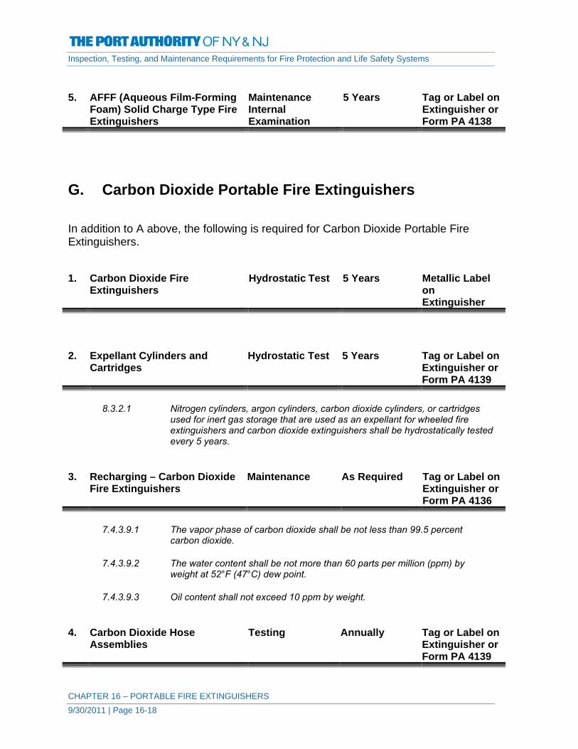
Inspection, Testing, and Maintenance Requirements for Fire Protection and Life Safety Systems
CHAPTER 16 – PORTABLE FIRE EXTINGUISHERS 9/30/2011 | Page 16-18
5. AFFF (Aqueous Film-Forming
Foam) Solid Charge Type Fire Extinguishers
Maintenance Internal Examination
5 Years Tag or Label on Extinguisher or Form PA 4138
G. Carbon Dioxide Portable Fire Extinguishers In addition to A above, the following is required for Carbon Dioxide Portable Fire Extinguishers. 1. Carbon Dioxide Fire
Extinguishers Hydrostatic Test 5 Years Metallic Label
on Extinguisher
2. Expellant Cylinders and
Cartridges Hydrostatic Test 5 Years Tag or Label on
Extinguisher or Form PA 4139
8.3.2.1 Nitrogen cylinders, argon cylinders, carbon dioxide cylinders, or cartridges
used for inert gas storage that are used as an expellant for wheeled fire extinguishers and carbon dioxide extinguishers shall be hydrostatically tested every 5 years.
3. Recharging – Carbon Dioxide
Fire Extinguishers Maintenance As Required Tag or Label on
Extinguisher or Form PA 4136
7.4.3.9.1 The vapor phase of carbon dioxide shall be not less than 99.5 percent
carbon dioxide.
7.4.3.9.2 The water content shall be not more than 60 parts per million (ppm) by weight at 52°F (47°C) dew point.
7.4.3.9.3 Oil content shall not exceed 10 ppm by weight.
4. Carbon Dioxide Hose
Assemblies Testing Annually Tag or Label on
Extinguisher or Form PA 4139

Inspection, Testing, and Maintenance Requirements for Fire Protection and Life Safety Systems
CHAPTER 16 – PORTABLE FIRE EXTINGUISHERS 9/30/2011 | Page 16-19
7.3.1.3 A conductivity test shall be conducted annually on all carbon dioxide hose assemblies.
7.3.1.3.1 Carbon dioxide hose assemblies that fail the conductivity test shall be
replaced.
7.3.1.3.2 Carbon dioxide hose assemblies that pass a conductivity test shall have the test information recorded on a suitable metallic label or equally durable material that has a minimum size of 1 2 in. × 3 in. (13 mm × 76 mm).
7.3.1.3.2.1 The label shall be affixed to the hose by means of a heatless process.
7.3.1.3.2.2 The label shall include the following information:
(1) Month and year the test was performed, indicated by perforation, such as is done by a hand punch
(2) Name or initials of person performing the test and the name of the agency performing the test
5. Expellant Cylinders and
Cartridges Hydrostatic Test 5 Years Tag or Label on
Extinguisher or Form PA 4139
8.3.2.1 Nitrogen cylinders, argon cylinders, carbon dioxide cylinders, or cartridges
used for inert gas storage that are used as an expellant for wheeled fire extinguishers and carbon dioxide extinguishers shall be hydrostatically tested every 5 years.
6. Carbon Dioxide Fire
Extinguishers Maintenance Internal Examination
5 Years Tag or Label on Extinguisher or Form PA 4138
H. Wetting Agent Portable Fire Extinguishers In addition to A above, the following is required for Wetting Agent Portable Fire Extinguishers. 1. Wetting Agent Fire
Extinguishers Hydrostatic Test 5 Years Metallic Label
on Extinguisher

Inspection, Testing, and Maintenance Requirements for Fire Protection and Life Safety Systems
CHAPTER 16 – PORTABLE FIRE EXTINGUISHERS 9/30/2011 | Page 16-20
2. Wetting Agent Fire Extinguishers
Maintenance Internal Examination
Annually Tag or Label on Extinguisher or Form PA 4137
3. Recharging – Wetting Agent
Fire Extinguishers Maintenance Annually Tag or Label on
Extinguisher or Form PA 4136
7.4.2.2 The agent in stored-pressure wetting agent fire extinguishers shall be
replaced annually.
7.4.2.2.1 Only the agent specified on the nameplate shall be used for recharging.
7.4.2.2.2 The use of water or any other additives shall be prohibited. I. Halogenated Agent Portable Fire Extinguishers In addition to A above, the following is required for Halogenated Agent Portable Fire Extinguishers. 1. Halogenated Agent Fire
Extinguishers Hydrostatic Test 12 Years Metallic Label
on Extinguisher
2. Recharging – Halogenated
Agent Fire Extinguishers Maintenance As Required Tag or Label on
Extinguisher or Form PA 4136
7.4.3.7 Halogenated agent fire extinguishers shall be charged only with the proper
type and weight of agent as specified on the nameplate.
7.4.3.8 Halogenated Agent Re-Use.
7.4.3.8.1 The removal of Halon 1211 from fire extinguishers shall be done only using a listed halon closed recovery system.
7.4.3.8.2 The removal of agent from other halogenated agent fire extinguishers shall
be done only using a closed recovery system.
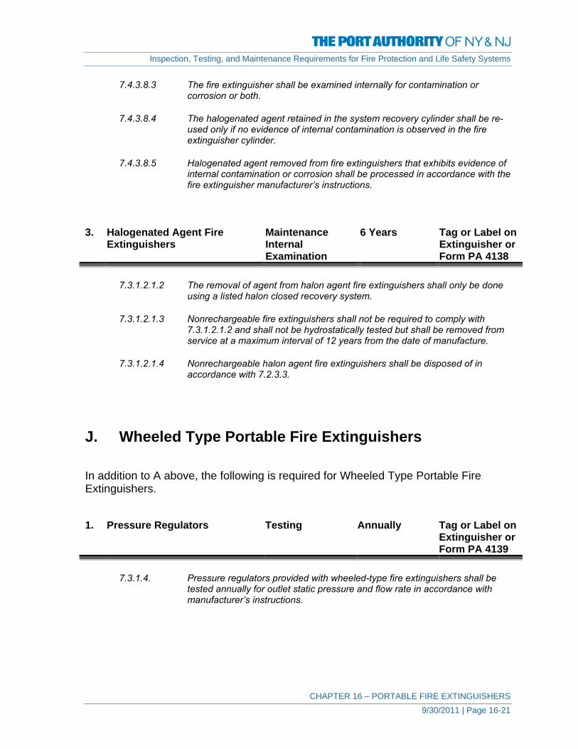
Inspection, Testing, and Maintenance Requirements for Fire Protection and Life Safety Systems
CHAPTER 16 – PORTABLE FIRE EXTINGUISHERS 9/30/2011 | Page 16-21
7.4.3.8.3 The fire extinguisher shall be examined internally for contamination or corrosion or both.
7.4.3.8.4 The halogenated agent retained in the system recovery cylinder shall be re-
used only if no evidence of internal contamination is observed in the fire extinguisher cylinder.
7.4.3.8.5 Halogenated agent removed from fire extinguishers that exhibits evidence of
internal contamination or corrosion shall be processed in accordance with the fire extinguisher manufacturer’s instructions.
3. Halogenated Agent Fire
Extinguishers Maintenance Internal Examination
6 Years Tag or Label on Extinguisher or Form PA 4138
7.3.1.2.1.2 The removal of agent from halon agent fire extinguishers shall only be done
using a listed halon closed recovery system.
7.3.1.2.1.3 Nonrechargeable fire extinguishers shall not be required to comply with 7.3.1.2.1.2 and shall not be hydrostatically tested but shall be removed from service at a maximum interval of 12 years from the date of manufacture.
7.3.1.2.1.4 Nonrechargeable halon agent fire extinguishers shall be disposed of in
accordance with 7.2.3.3. J. Wheeled Type Portable Fire Extinguishers In addition to A above, the following is required for Wheeled Type Portable Fire Extinguishers. 1. Pressure Regulators Testing Annually Tag or Label on
Extinguisher or Form PA 4139
7.3.1.4. Pressure regulators provided with wheeled-type fire extinguishers shall be
tested annually for outlet static pressure and flow rate in accordance with manufacturer’s instructions.

Inspection, Testing, and Maintenance Requirements for Fire Protection and Life Safety Systems
CHAPTER 16 – PORTABLE FIRE EXTINGUISHERS 9/30/2011 | Page 16-22
2. Expellant Cylinders and
Cartridges Hydrostatic Test 5 Years Tag or Label on
Extinguisher or Form PA 4139
8.3.2.1 Nitrogen cylinders, argon cylinders, carbon dioxide cylinders, or cartridges
used for inert gas storage that are used as an expellant for wheeled fire extinguishers and carbon dioxide extinguishers shall be hydrostatically tested every 5 years.
K. Wet Chemical Portable Fire Extinguishers In addition to A above, the following is required for Wet Chemical Portable Fire Extinguishers. 1. Wet Chemical Fire
Extinguishers Hydrostatic Test 5 Years Metallic Label
on Extinguisher
2. Recharging – Wet Chemical
Fire Extinguishers Maintenance As Required Tag or Label on
Extinguisher or Form PA 4136
7.4.3.11.1 Wet chemical agents shall not be re-used.
7.4.3.11.2 If a wet chemical extinguisher is partially discharged, all remaining wet
chemical shall be discarded.
7.4.3.11.3 Wet chemical agent shall be discarded and replaced at the hydrostatic test interval.
7.4.3.11.3.1 Only the agent specified on the extinguisher nameplate shall be used for
recharge. 3. Wet Chemical Fire
Extinguishers Maintenance Internal Examination
5 Years Tag or Label on Extinguisher or Form PA 4138
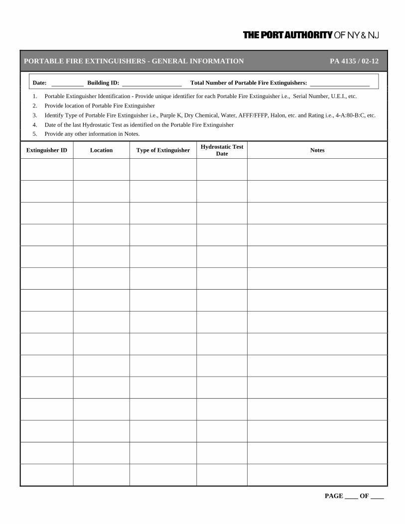
PORTABLE FIRE EXTINGUISHERS - GENERAL INFORMATION PA 4135 / 02-12
Date: Building ID: Total Number of Portable Fire Extinguishers:
1. Portable Extinguisher Identification - Provide unique identifier for each Portable Fire Extinguisher i.e., Serial Number, U.E.I., etc. 2. Provide location of Portable Fire Extinguisher 3. Identify Type of Portable Fire Extinguisher i.e., Purple K, Dry Chemical, Water, AFFF/FFFP, Halon, etc. and Rating i.e., 4-A:80-B:C, etc. 4. Date of the last Hydrostatic Test as identified on the Portable Fire Extinguisher 5. Provide any other information in Notes.
Extinguisher ID Location Type of Extinguisher Hydrostatic Test Date Notes
PAGE ____ OF ____

PORTABLE FIRE EXTINGUISHERS - INSPECTION, MAINTENANCE AND PA 4136 / 02-12 RECHARGE SUMMARY
Building ID: Total Number of Portable Extinguishers:
Documentation indicating completion of inspections, maintenance, and recharge signifies conformance with all requirements for that task. Deviation from completing required tasks should be identified in Notes. The reverse side of this form can be used for additional notation.
Extinguisher ID
Use (M) for monthly inspections. Use (A) for annual maintenance check. Use (R) for extinguisher recharge.
Notes
J F M A M J J A S O N D

PORTABLE FIRE EXTINGUISHERS - ANNUAL MAINTENANCE SUMMARY PA 4137 / 02-12
Building ID: Total Number of Portable Extinguishers:
Provide date for documentation indicating completion of maintenance and signifying conformance with all requirements for that task. Deviation from completing required tasks should be identified in Notes. The reverse side of this form can be used for additional notation.
Extinguisher ID
Load
ed-S
tream
and
Ant
ifree
ze –
In
tern
al E
xam
inat
ion
Stor
ed P
ress
ure/
Load
ed S
tream
C
harg
e
Stor
ed P
ress
ure
Fire
Ext
ingu
ishe
rs
Subj
ecte
d To
Tem
pera
ture
s at o
r A
bove
Its L
iste
d R
atin
g
Wet
ting
Age
nt -
Inte
rnal
Exa
min
atio
n
Wat
er a
nd P
ump
Tank
Cal
cium
Chl
orid
e B
ased
Fire
Ext
ingu
ishe
rs –
Inte
rnal
Ex
amin
atio
n
Dry
Che
mic
al /
Dry
Pow
der
Car
tridg
e an
d C
ylin
der O
pera
ted,
With
M
ild S
teel
She
ll Fi
re E
xtin
guis
hers
- In
tern
al E
xam
inat
ion
Car
tridg
e an
d C
ylin
der O
pera
ted,
With
M
ild S
teel
She
ll Fi
re E
xtin
guis
hers
- In
tern
al E
xam
inat
ion
Notes
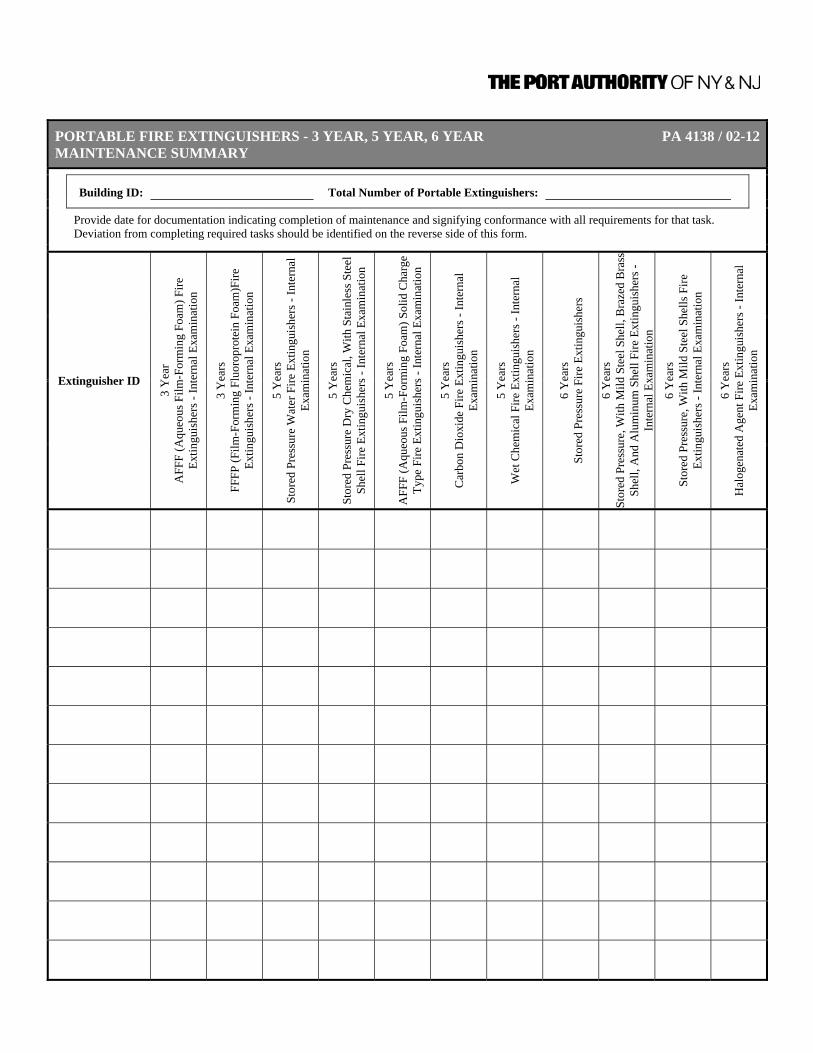
PORTABLE FIRE EXTINGUISHERS - 3 YEAR, 5 YEAR, 6 YEAR PA 4138 / 02-12MAINTENANCE SUMMARY
Building ID: Total Number of Portable Extinguishers:
Provide date for documentation indicating completion of maintenance and signifying conformance with all requirements for that task. Deviation from completing required tasks should be identified on the reverse side of this form.
Extinguisher ID
3 Y
ear
AFF
F (A
queo
us F
ilm-F
orm
ing
Foam
) Fire
Ex
tingu
ishe
rs -
Inte
rnal
Exa
min
atio
n
3 Y
ears
FF
FP (F
ilm-F
orm
ing
Fluo
ropr
otei
n Fo
am)F
ire
Extin
guis
hers
- In
tern
al E
xam
inat
ion
5 Y
ears
St
ored
Pre
ssur
e W
ater
Fire
Ext
ingu
ishe
rs -
Inte
rnal
Ex
amin
atio
n
5 Y
ears
St
ored
Pre
ssur
e D
ry C
hem
ical
, With
Sta
inle
ss S
teel
Sh
ell F
ire E
xtin
guis
hers
- In
tern
al E
xam
inat
ion
5 Y
ears
A
FFF
(Aqu
eous
Film
-For
min
g Fo
am) S
olid
Cha
rge
Type
Fire
Ext
ingu
ishe
rs -
Inte
rnal
Exa
min
atio
n
5 Y
ears
C
arbo
n D
ioxi
de F
ire E
xtin
guis
hers
- In
tern
al
Exam
inat
ion
5 Y
ears
W
et C
hem
ical
Fire
Ext
ingu
ishe
rs -
Inte
rnal
Ex
amin
atio
n
6 Y
ears
St
ored
Pre
ssur
e Fi
re E
xtin
guis
hers
6 Y
ears
St
ored
Pre
ssur
e, W
ith M
ild S
teel
She
ll, B
raze
d B
rass
Sh
ell,
And
Alu
min
um S
hell
Fire
Ext
ingu
ishe
rs -
Inte
rnal
Exa
min
atio
n
6 Y
ears
St
ored
Pre
ssur
e, W
ith M
ild S
teel
She
lls F
ire
Extin
guis
hers
- In
tern
al E
xam
inat
ion
6 Y
ears
H
alog
enat
ed A
gent
Fire
Ext
ingu
ishe
rs -
Inte
rnal
Ex
amin
atio
n

PORTABLE FIRE EXTINGUISHERS - TEST SUMMARY PA 4139 / 02-12
Building ID: Total Number of Portable Extinguishers:
Provide date for documentation indicating completion of maintenance and signifying conformance with all requirements for that task. Deviation from completing required tasks should be identified in Notes. The reverse side of this form can be used for additional notation.
Extinguisher ID Annually
Wheeled Extinguisher Pressure Regulators
Annually Carbon Dioxide Hose
Assemblies
5 Years Expellant Cylinders
and Cartridges Notes

Inspection, Testing, and Maintenance Requirements for Fire Protection and Life Safety Systems
CHAPTER 17 – VALVES AND FIRE DEPARTMENT CONNECTIONS 9/30/2011 | Page 17-1
CHAPTER 17 – VALVES AND FIRE DEPARTMENT
CONNECTIONS
GENERAL INFORMATION
This Chapter applies to all valves and fire department connections that may or may not be covered in other Chapters of this manual. Examples include, but are not limited to, curb box valves on water mains to fire hydrants, post indicator valves on lead-in connections, control valves for wall hydrants, control valves on water supplies for water storage tanks, and backflow-preventers on water supply piping. Noting that alarm valves, dry pipe valves, pre-action / deluge valves are a principal component of automatic sprinkler and standpipe systems, requirements for these valves are covered in Chapters 1 and 2 respectively. That information is not duplicated in this chapter. Requirements for other valves, such as pressure reducing valves, may be listed in other chapters but are duplicated in this chapter. The requirements in all chapters are the same and can be referenced or cross referenced as necessary.
DEFINITIONS Control Valve. A valve controlling flow to water-based fire protection
systems. Control valves do not include hose valves, inspector’s test valves, drain valves, trim valves for dry pipe, preaction and deluge valves, check valves, or relief valves.
Deluge Valve. A water supply control valve intended to be operated by
actuation of an automatic detection system that is installed in the same area as the water spray nozzles. Each control valve also shall be capable of manual operation.
Double Check Valve Assembly (DCVA). This assembly consists of two internally loaded check
valves, either springloaded or internally weighted, installed as a unit between two tightly closing resilient-seated shutoff valves as an assembly, and fittings with properly located resilient-seated test cocks.

Inspection, Testing, and Maintenance Requirements for Fire Protection and Life Safety Systems
CHAPTER 17 – VALVES AND FIRE DEPARTMENT CONNECTIONS 9/30/2011 | Page 17-2
Emergency Impairment. A condition where a waterbased fire protection system or
portion thereof is out of order due to an unexpected occurrence, such as a ruptured pipe, an operated sprinkler, or an interruption of the water supply to the system.
Fire Department Connection. A connection through which the fire department can pump
supplemental water into the sprinkler system, standpipe, or other system furnishing water for fire extinguishment to supplement existing water supplies.
Hose Valve. The control valve to an individual hose connection. Impairment. A shutdown of a system or portion thereof. Preplanned Impairment. A condition where a waterbased fire protection system or a
portion thereof is out of service due to work that has been planned in advance, such as revisions to the water supply or sprinkler system piping.
Pressure Control Valve. A pilot-operated pressure reducing valve designed for the
purpose of reducing the downstream water pressure to a specific value under both flowing (residual) and nonflowing (static) conditions.
Pressure Reducing Valve. A valve designed for the purpose of reducing the
downstream water pressure under both flowing (residual) and nonflowing (static) conditions.
Pressure Regulating Device. A device designed for the purpose of reducing, regulating,
controlling, or restricting water pressure. Examples include pressure reducing valves, pressure control valves, and pressure restricting devices.
Pressure Restricting Device. A valve or device designed for the purpose of reducing the
downstream water pressure under flowing (residual) conditions only.
Reduced-Pressure Principle Backflow Two independently acting check valves together with a Prevention Assembly (RPBA) hydraulically operating, mechanically independent pressure
differential relief valve located between the check valves and below the first check valve. These units are located between two tightly closed resilient-seated shutoff valves, as an assembly, and are equipped with properly located resilient-seated test cocks.

Inspection, Testing, and Maintenance Requirements for Fire Protection and Life Safety Systems
CHAPTER 17 – VALVES AND FIRE DEPARTMENT CONNECTIONS 9/30/2011 | Page 17-3
A. ALL VALVES AND FIRE DEPARTMENT CONNECTIONS 1. Existing Valves
General Information Update Annually Form PA 4141
Review General Information Form for all Valves and Fire Department Connections, update as required.
2. Existing Fire Department
Connections General Information
Update Annually Form PA 4142
Review General Information Form for all Valves and Fire Department Connections, update as required.
3. New or Altered Valves
General Information Update As Required Form PA 4141
Complete General Information Form for new Valves and Fire Department Connections or update General Information Form for Valves and Fire Department Connections that have been altered to include repairs and/or modifications to components.
4. New or Altered Fire
Department Connections General Information
Update As Required Form PA 4142
Complete General Information Form for new Valves and Fire Department Connections or update General Information Form for Valves and Fire Department Connections that have been altered to include repairs and/or modifications to components.
B. CONTROL VALVES In addition to A above, the following is required for Control Valves 1. Control Valves – Sealed Inspection Weekly Form PA 4001
12.3.2.1 All valves shall be inspected weekly.

Inspection, Testing, and Maintenance Requirements for Fire Protection and Life Safety Systems
CHAPTER 17 – VALVES AND FIRE DEPARTMENT CONNECTIONS 9/30/2011 | Page 17-4
12.3.2.2 The valve inspection shall verify that the valves are in the following condition:
(1) In the normal open or closed position (2) Properly sealed, locked, or supervised (3) Accessible (4) Provided with appropriate wrenches (5) Free from external leaks (6) Provided with appropriate identification
2. Control Valves –
Locked/Supervised Inspection Monthly Form PA 4002
12.3.2.1.1 Valves secured with locks or supervised in accordance with applicable NFPA
standards shall be permitted to be inspected monthly.
12.3.2.2 The valve inspection shall verify that the valves are in the following condition: (1) In the normal open or closed position (2) Properly sealed, locked, or supervised (3) Accessible (4) Provided with appropriate wrenches (5) Free from external leaks (6) Provided with appropriate identification
3. Control Valves Testing Annually Form PA 4005
12.3.3.1 Each control valve shall be operated annually through its full range and returned to its normal position. The testing required by 12.3.3.1 should include counting the number of turns needed to fully close and open the valve. Also, the valve stem should be lubricated before opening and closing.
12.3.3.2 Post indicator valves shall be opened until spring or torsion is felt in the rod,
indicating that the rod has not become detached from the valve. 4. Control Valves Testing Semi-Annually Form PA 4004
12.3.3.5.1 Valve supervisory switches shall be tested semiannually.
12.3.3.5.2 A distinctive signal shall indicate movement from the valve’s normal position during either the first two revolutions of a hand wheel or when the stem of the valve has moved one-fifth of the distance from its normal position.
12.3.3.5.3 The signal shall not be restored at any valve position except the normal position.

Inspection, Testing, and Maintenance Requirements for Fire Protection and Life Safety Systems
CHAPTER 17 – VALVES AND FIRE DEPARTMENT CONNECTIONS 9/30/2011 | Page 17-5
5. Control Valves Maintenance Annually Form PA 4011
12.3.4.1 The operating stems of outside screw and yoke valves shall be lubricated annually.
12.3.4.2 The valve then shall be completely closed and reopened to test its operation
and distribute the lubricant. C. Check Valves In addition to A above, the following is required for Check Valves 1. Check Valves Inspection 5 Years Form PA 4143
12.4.2.1 Valves shall be inspected internally every 5 years to verify that all components operate correctly, move freely, and are in good condition.
2. Check Valves Maintenance As Required Form PA 4149
12.4.2.2 Internal components shall be cleaned, repaired, or replaced as necessary in accordance with the manufacturer’s instructions.
D. Pressure Reducing & Relief Valves In addition to A above, the following is required for Pressure Reducing & Relief Valves 1. Pressure Reducing & Relief
Valves – Sprinkler System Inspection Quarterly Form PA 4150
12.5.1.1 All valves shall be inspected quarterly to verify that the valves are in the
following condition: (1) In the open position (2) Not leaking (3) Maintaining downstream pressures in accordance with the design criteria (4) In good condition, with handwheels installed and unbroken

Inspection, Testing, and Maintenance Requirements for Fire Protection and Life Safety Systems
CHAPTER 17 – VALVES AND FIRE DEPARTMENT CONNECTIONS 9/30/2011 | Page 17-6
2. Pressure Reducing & Relief
Valves – Sprinkler Systems Testing Annually Form PA 4150
12.5.1.3 A partial flow test adequate to move the valve from its seat shall be
conducted annually. 3. Pressure Reducing & Relief
Valves – Sprinkler System Testing 5 Years Form PA 4150
12.5.1.2 A full flow test shall be conducted on each valve at 5-year intervals and shall
be compared to previous test results.
Document results of Test in Notes on Form PA 4150. 4. Pressure Reducing & Relief
Valves – Hose Connection/Hose Rack Assembly
Inspection Quarterly Form PA 4150
12.5.2 Hose Connection Pressure Reducing Valves.
12.5.2.1 All valves shall be inspected quarterly to verify the following:
(1) The handwheel is not broken or missing (2) The outlet hose threads are not damaged (3) No leaks are present (4) The reducer and the cap are not missing
12.5.3 Hose Rack Assembly Pressure Reducing Valves.
12.5.3.1 All valves shall be inspected quarterly to verify the following:
(1) The handwheel is not broken or missing (2) No leaks are present
5. Pressure Reducing & Relief
Valves – Hose Connection/Hose Rack Assembly
Testing Annually Form PA 4150
12.5.2 Hose Connection Pressure Reducing Valves.
12.5.2.3 A partial flow test adequate to move the valve from its seat shall be
conducted annually.
12.5.3 Hose Rack Assembly Pressure Reducing Valves.
12.5.3.3 A partial flow test adequate to move the valve from its seat shall be conducted annually.

Inspection, Testing, and Maintenance Requirements for Fire Protection and Life Safety Systems
CHAPTER 17 – VALVES AND FIRE DEPARTMENT CONNECTIONS 9/30/2011 | Page 17-7
6. Pressure Reducing & Relief
Valves - Hose Connection/Hose Rack Assembly
Testing 5 Years Form PA 4150
12.5.2 Hose Connection Pressure Reducing Valves.
12.5.2.2 A full flow test shall be conducted on each valve at 5-year intervals and shall
be compared to the previous test results.
12.5.3 Hose Rack assembly Pressure Reducing Valves.
12.5.3.2 A full flow test shall be conducted on each valve at 5-year intervals and shall be compared to the previous test results.
7. Pressure Reducing & Relief
Valves Inspection Quarterly Form PA 4150
12.5.4.1 All pressure reducing valves installed on fire protection systems not covered
by 12.5.1, 12.5.2, or 12.5.3 shall be inspected in accordance with 12.5.1.1.
12.5.1.1 All valves shall be inspected quarterly to verify that the valves are in the following condition: (1) In the open position (2) Not leaking (3) Maintaining downstream pressures in accordance with the design criteria (4) In good condition, with handwheels installed and unbroken
8. Pressure Reducing & Relief
Valves Testing 5 Years Form PA 4150
12.5.4 Pressure Reducing Valves.
12.5.4.2 All pressure reducing valves installed on fire protection systems not covered
by 12.5.1, 12.5.2, or 12.5.3 shall be tested in accordance with 12.5.1.2.
12.5.1.2 A full flow test shall be conducted on each valve at 5-year intervals and shall be compared to previous test results.

Inspection, Testing, and Maintenance Requirements for Fire Protection and Life Safety Systems
CHAPTER 17 – VALVES AND FIRE DEPARTMENT CONNECTIONS 9/30/2011 | Page 17-8
E. Backflow Prevention Assemblies In addition to A above, the following is required for Backflow Prevention Assemblies 1. Backflow Prevention Assemblies Inspection Weekly Form PA 4144
12.6.1.1 The double check assembly (DCA) valves and double check detector assembly (DCDA) valve shall be inspected weekly to ensure that the OS&Y isolation valves are in the normal open position.
12.6.1.2 Reduced pressure assemblies (RPA) and reduced pressure detector
assemblies (RPDA) shall be inspected weekly to ensure that the differential-sensing valve relief port is not continuously discharging and the OS&Y isolation valves are in the normal open position.
A.12.6.1.2 Intermittent discharge from a differential-sensing valve relief port is normal.
Continuous discharge is a sign of malfunction of either or both of the check valves, and maintenance is necessary.
2. Backflow Prevention Assemblies Inspection Monthly Form PA 4145
12.6.1.1.1 Double check assembly (DCA) valves secured with locks or electrically supervised in accordance with applicable NFPA standards shall be inspected monthly.
12.6.1.2.1 Reduced pressure assemblies (RPA) and reduced pressure detector
assemblies (RPDA) secured with locks or electrically supervised in accordance with applicable NFPA standards shall be inspected monthly.
3. Backflow Prevention Assemblies Testing Annually Form PA 4146
12.6.2.1 All backflow preventers installed in fire protection system piping shall be tested annually in accordance with the following:
1) A forward flow test shall be conducted at the system demand,
including hose stream demand, where hydrants or inside hose stations are located downstream of the backflow preventer.
2) A backflow performance test, as required by the authority having
jurisdiction, shall be conducted at the completion of the forward flow test.

Inspection, Testing, and Maintenance Requirements for Fire Protection and Life Safety Systems
CHAPTER 17 – VALVES AND FIRE DEPARTMENT CONNECTIONS 9/30/2011 | Page 17-9
A.12.6.2.1 The full flow test of the backflow prevention valve can be performed with a test header or other connections downstream of the valve. A bypass around the check valve in the fire department connection line with a control valve in the normally closed position can be an acceptable arrangement. When flow to a visible drain cannot be accomplished, closed loop flow can be acceptable if a flow meter or sight glass is incorporated into the system to ensure flow.
12.6.2.1.1 For backflow preventers sized 50.8mm (2 in.) and under, the forward flow
test shall be acceptable to conduct without measuring flow, where the test outlet is of a size to flow the system demand.
12.6.2.1.2 Where water rationing shall be enforced during shortages lasting more than 1
year, an internal inspection of the backflow preventer to ensure the check valves will fully open shall be acceptable in lieu of conducting the annual forward flow test.
12.6.2.1.3 Where connections do not permit a full flow test, tests shall be completed at
the maximum flow rate possible.
12.6.2.1.4 The forward flow test shall not be required where annual fire pump testing causes the system demand to flow through the backflow preventer device.
12.6.2.2 All backflow devices installed in fire protection water supply shall be tested
annually at the designed flow rate of the fire protection system, including required hose stream demands.
A.12.6.2.2 The tests required by 12.6.2 typically test only for operation of the device
under backflow conditions. Forward-flow test conditions are required by other portions of this standard.
12.6.2.2.1 Where connections do not permit a full flow test, tests shall be completed at
the maximum flow rate possible. 4. Backflow Prevention
Assemblies Maintenance As Required Form PA 4149
12.6.3.1 Maintenance of all backflow prevention assemblies shall be conducted by a
trained individual following the manufacturer’s instructions in accordance with the procedure and policies of the authority having jurisdiction.
12.6.3.2 Rubber parts shall be replaced in accordance with the frequency required by
the authority having jurisdiction and the manufacturer’s instructions.

Inspection, Testing, and Maintenance Requirements for Fire Protection and Life Safety Systems
CHAPTER 17 – VALVES AND FIRE DEPARTMENT CONNECTIONS 9/30/2011 | Page 17-10
F. Fire Department Connections In addition to A above, the following is required for Fire Department Connections 1. Fire Department Connections Inspection Quarterly Form PA 4147
12.7.1 Fire department connections shall be inspected quarterly. The inspection shall verify the following:
1) The fire department connections are visible and accessible.
2) Couplings or swivels are not damaged and rotate smoothly.
3) Plugs or caps are in place and undamaged.
4) Gaskets are in place and in good condition.
5) Identification signs are in place.
6) The check valve is not leaking.
7) The automatic drain valve is in place and operating properly.
8) The fire department connection clapper(s) is in place and operating
properly.
12.7.2 If fire department connection plugs or caps are not in place, the interior of the connection shall be inspected for obstructions, and it shall be verified that the fire department connection clapper is operational over its full range.
12.7.3 Components shall be repaired or replaced as necessary in accordance with the manufacturer’s instructions. Any obstructions that are present shall be removed.
2. Fire Department Connections
Standpipe Systems Testing 5 Year Form PA 4148
912.6 Sprinkler system and standpipe system fire department connections shall be
periodically inspected, tested, serviced and otherwise maintained in accordance with Section 901.6 and NFPA 25. Upon order of the commissioner, but at least once every 5 years, such fire department connections shall be subjected to a hydrostatic pressure test to demonstrate their suitability for department use. The test shall be conducted in accordance with the rules and at the owner's risk, by his or her representative before a representative of the department.

Inspection, Testing, and Maintenance Requirements for Fire Protection and Life Safety Systems
CHAPTER 17 – VALVES AND FIRE DEPARTMENT CONNECTIONS 9/30/2011 | Page 17-11
(c) Standpipe Pressure and Flow Tests. Standpipe systems shall be tested in accordance with the following procedures:
(1) Hydrostatic test
(A) A pressure of 50 psi in excess of static pressure shall be applied to
the entire system before replacing clappers in fire department connection check valves. Where intermediate tanks are provided, static pressure must be calculated from the roof tank.
(B) The test connection shall be made at the fire department connection.
(C) Standpipe systems shall not be tested using air or other pneumatic
methods.
(2) Flow test
(A) No flow test shall be conducted when the outdoor ambient temperature is below 32°F.
(B) Shut off supply to system (gravity tank or street supply).
(C) Drain system at lowest outlet available.
(D) Remove all lower check valve clappers and then replace the bonnet.
(E) Connect a control valve to each fire department connection. The
contractor shall provide a hose or make other provisions for draining of the water, so arranged as to hold the fire department connection clapper in an open position.
(F) Open the tank control valve or the street control valve and fill the
entire system.
(G) Stretch the hose to curb or to a drain, and flush each fire department connection until water runs clear. Shut the water off as soon as it runs clear.
(3) System restoration
(A) Restore the system by replacing clappers in check valve, opening all
control valves and filling the system.
(B) Properly vent all dead ends.
(C) Inspect drips after protection is restored, to check if the lower check valves are leaking.
(D) The contractor shall endeavor to ensure that the standpipe system is
not out of service overnight. If it is impracticable to restore the system for Fire Department use, the certificate of fitness holder shall notify the owner or building manager and the Department, by telephoning the Department communications office (dispatcher) for
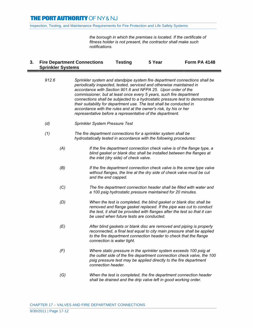
Inspection, Testing, and Maintenance Requirements for Fire Protection and Life Safety Systems
CHAPTER 17 – VALVES AND FIRE DEPARTMENT CONNECTIONS 9/30/2011 | Page 17-12
the borough in which the premises is located. If the certificate of fitness holder is not present, the contractor shall make such notifications.
3. Fire Department Connections
Sprinkler Systems Testing 5 Year Form PA 4148
912.6 Sprinkler system and standpipe system fire department connections shall be
periodically inspected, tested, serviced and otherwise maintained in accordance with Section 901.6 and NFPA 25. Upon order of the commissioner, but at least once every 5 years, such fire department connections shall be subjected to a hydrostatic pressure test to demonstrate their suitability for department use. The test shall be conducted in accordance with the rules and at the owner's risk, by his or her representative before a representative of the department.
(d) Sprinkler System Pressure Test
(1) The fire department connections for a sprinkler system shall be
hydrostatically tested in accordance with the following procedures:
(A) If the fire department connection check valve is of the flange type, a blind gasket or blank disc shall be installed between the flanges at the inlet (dry side) of check valve.
(B) If the fire department connection check valve is the screw type valve
without flanges, the line at the dry side of check valve must be cut and the end capped.
(C) The fire department connection header shall be filled with water and
a 100 psig hydrostatic pressure maintained for 20 minutes.
(D) When the test is completed, the blind gasket or blank disc shall be removed and flange gasket replaced. If the pipe was cut to conduct the test, it shall be provided with flanges after the test so that it can be used when future tests are conducted.
(E) After blind gaskets or blank disc are removed and piping is properly
reconnected, a final test equal to city main pressure shall be applied to the fire department connection header to check that the flange connection is water tight.
(F) Where static pressure in the sprinkler system exceeds 100 psig at
the outlet side of the fire department connection check valve, the 100 psig pressure test may be applied directly to the fire department connection header.
(G) When the test is completed, the fire department connection header
shall be drained and the drip valve left in good working order.

Inspection, Testing, and Maintenance Requirements for Fire Protection and Life Safety Systems
CHAPTER 17 – VALVES AND FIRE DEPARTMENT CONNECTIONS 9/30/2011 | Page 17-13
(H) When the fire department connections for perforated pipe systems are tested, the perforated branch lines shall be backed out and openings plugged.
(I) Sprinkler system fire department connections shall not be tested
using air or other pneumatic methods. (2) System restoration
(A) After maintaining the pressure at 100 psig for 20 minutes, the system
shall be restored by removing plugs and reconnecting branch lines.
(B) The contractor shall endeavor to ensure that the sprinkler system is not out of service overnight. If it is impracticable to restore the system for Fire Department use, the certificate of fitness holder shall notify the owner or building manager and the Department, by telephoning the Department communications office (dispatcher) for the borough in which the premises is located. If the certificate of fitness holder is not present, the contractor shall make such notifications.

VALVES AND FIRE DEPARTMENT CONNECTIONS - PA 4141 / 02-12GENERAL INFORMATION - VALVES
Building ID: Total Number of Valves:
1. Valve identification - Provide unique identifier for each valve.
2. Provide location of valve.
3. Identify the type of valve - Check, Backflow Prevention Assembly, OS&Y, Butterfly, Pressure Reducing, etc.
4. Identify if control valve is sealed (S), locked (L), or electronically supervised with a tamper switch (T).
5. Provide any other pertinent information in Notes.
Valves include Check Valves, Control Valves not included in other Sprinkler Standpipe System info, Backflow Prevention Assemblies, Pressure Reducing & Relief Valves, etc.
Valve ID U.E.I. Location Type of Valve
(S)ealed (L)ocked
(T)amper Sw. Notes
PAGE ____ OF ____

VALVES AND FIRE DEPARTMENT CONNECTIONS - GENERAL INFORMATION - PA 4142 / 02-12 FIRE DEPARTMENT CONNECTIONS
Building ID: Total Number of Fire Dept. Connections:
1. Fire Department Connection (FDC) Identification - Provide unique identifier for each FDC. 2. Provide location of Fire Department Connection. 3. Identify the number of hose connections and diameter. Example - 2, 2-1/2 inches. 4. Identify the hose connection thread type: NST = National Standard Thread; NYC = New York Corporation thread. 5. Provide any other pertinent information in Notes.
FDC ID U.E.I. Location Hose Connection
Size Hose Thread Type Notes

VALVES AND FIRE DEPARTMENT CONNECTIONS - 5-YEAR INSPECTION - PA 4143 / 02-12 CHECK VALVES
Building ID: System ID / U.E.I.:
Date: Inspector:
Y = Satisfactory N = Unsatisfactory (explain on reverse)
Valves are internally inspected to verify that all components operate correctly, move freely, and are in good condition.
Check Valve ID U.E.I. Location Y / N Notes
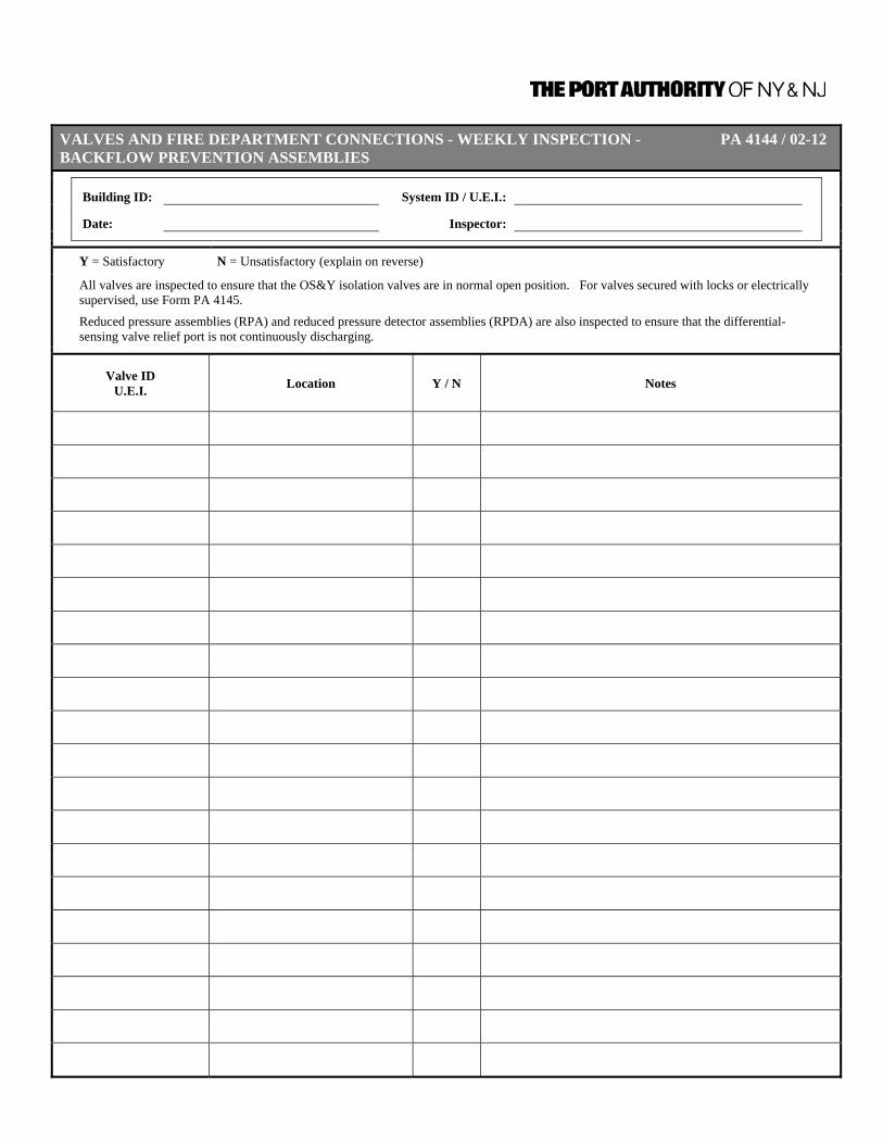
VALVES AND FIRE DEPARTMENT CONNECTIONS - WEEKLY INSPECTION - PA 4144 / 02-12 BACKFLOW PREVENTION ASSEMBLIES
Building ID: System ID / U.E.I.:
Date: Inspector:
Y = Satisfactory N = Unsatisfactory (explain on reverse)
All valves are inspected to ensure that the OS&Y isolation valves are in normal open position. For valves secured with locks or electrically supervised, use Form PA 4145.
Reduced pressure assemblies (RPA) and reduced pressure detector assemblies (RPDA) are also inspected to ensure that the differential-sensing valve relief port is not continuously discharging.
Valve ID U.E.I. Location Y / N Notes
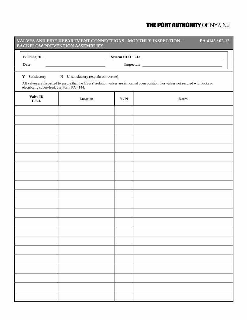
VALVES AND FIRE DEPARTMENT CONNECTIONS - MONTHLY INSPECTION - PA 4145 / 02-12BACKFLOW PREVENTION ASSEMBLIES
Building ID: System ID / U.E.I.:
Date: Inspector:
Y = Satisfactory N = Unsatisfactory (explain on reverse)
All valves are inspected to ensure that the OS&Y isolation valves are in normal open position. For valves not secured with locks or electrically supervised, use Form PA 4144.
Valve ID U.E.I. Location Y / N Notes
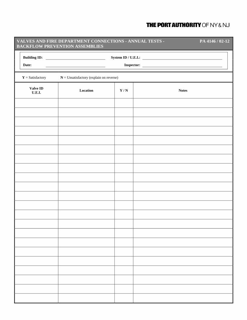
VALVES AND FIRE DEPARTMENT CONNECTIONS - ANNUAL TESTS - PA 4146 / 02-12BACKFLOW PREVENTION ASSEMBLIES
Building ID: System ID / U.E.I.:
Date: Inspector:
Y = Satisfactory N = Unsatisfactory (explain on reverse)
Valve ID U.E.I. Location Y / N Notes
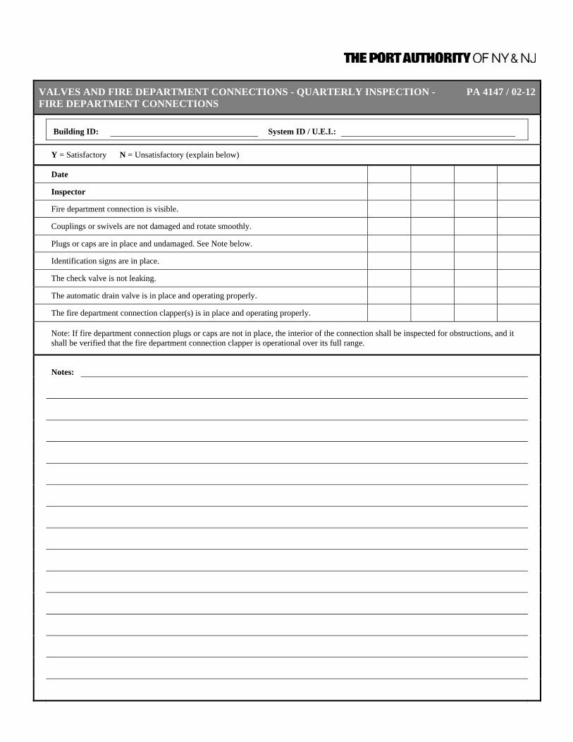
VALVES AND FIRE DEPARTMENT CONNECTIONS - QUARTERLY INSPECTION - PA 4147 / 02-12FIRE DEPARTMENT CONNECTIONS
Building ID: System ID / U.E.I.:
Y = Satisfactory N = Unsatisfactory (explain below)
Date Inspector Fire department connection is visible. Couplings or swivels are not damaged and rotate smoothly. Plugs or caps are in place and undamaged. See Note below. Identification signs are in place. The check valve is not leaking. The automatic drain valve is in place and operating properly. The fire department connection clapper(s) is in place and operating properly.
Note: If fire department connection plugs or caps are not in place, the interior of the connection shall be inspected for obstructions, and it shall be verified that the fire department connection clapper is operational over its full range.
Notes:

VALVES AND FIRE DEPARTMENT CONNECTIONS - 5-YEAR TESTS - PA 4148 / 02-12FIRE DEPARTMENT CONNECTIONS
Building ID: System ID / U.E.I.:
Y = Satisfactory N = Unsatisfactory (explain below)
Date Inspector Hydrostatic Pressure Test
Flow Test (Only required for fire department connections serviing standpipe systems.)
Notes:

VALVES AND FIRE DEPARTMENT CONNECTIONS - MAINTENANCE – VALVES PA 4149 / 02-12
Building ID: System ID / U.E.I.:
Date: Inspector:
Y = Satisfactory N = Unsatisfactory (explain on reverse)
Valves include Check Valves, Control Valves, Backflow Prevention Assemblies, Pressure Reducing & Relief Valves, etc.
Valve ID U.E.I. Location Y / N Notes

VALVES AND FIRE DEPARTMENT CONNECTIONS - INSPECTION/TEST - PA 4150 / 02-12PRESSURE REDUCING & RELIEF VALVES
Building ID: System ID / U.E.I.:
Date: Inspector:
Check type of Inspection or Test:
Quarterly Inspection - For valves: Valves in the open position, not leaking, maintain pressures, in good condition. For hose connections and assembly: Handwheel not broken, threads not damaged, no leaks, reducer and cap not missing. Annual Test - Partial flow test
5-Year Test - Full flow test
Valve / Hose Conn./ Hose Rack ID
U.E.I. Location (S)atisfactory /
(U)nsatisfactory Notes
PAGE ____ OF ____

Inspection, Testing, and Maintenance Requirements for Fire Protection and Life Safety Systems
A-1 (11-05-12)
Valid Pages
Page Issue No. Date
Page Issue No. Date
Page Issue No. Date
I……………………09-30-11 PA 4008……………03-30-12 4-1…………………09-30-11 II……………. …….09-30-11 PA 4009……………03-30-12 4-2…………………09-30-11 III………………..…09-30-11 PA 4010……………03-30-12 4-3…………….…..09-30-11 IV……………….….09-30-11 PA 4011……………03-30-12 4-4………………..09-30-11 V……………….…..11-05-12 2-1……….…………09-30-11 4-5…………….…..09-30-11 VI………….…..…...09-30-11 2-2………….………09-30-11 4-6…………………09-30-11 VII………………....09-30-11 2-3…..……………...09-30-11 4-7…………….….09-30-11 VIII…………….…. 09-30-11 2-4……..…………...09-30-11 4-8………………..09-30-11 IX………………… 09-30-11 2-5……..…….……..09-30-11 4-9…………….….09-30-11 X…………………… 09-30-11 2-6…. .….………….09-30-11 4-10……………….09-30-11 1-1……………….…09-30-11 2-7………………….09-30-11 PA 4031………….03-30-12 1-2……………….…09-30-11 2-8………………….09-30-11 PA 4032………….03-30-12 1-3……………….…09-30-11 2-9………..………...09-30-11 PA 4033……...….03-30-12 1-4……………….…09-30-11 2-10………………...09-30-11 PA 4034……..…..03-30-12 1-5……………….…09-30-11 2-11…….………….09-30-11 PA 4035………….03-30-12 1-6……………….…09-30-11 PA 4013…….……..03-30-12 PA 4036………….03-30-12 1-7……………….…09-30-11 PA 4014…...………03-30-12 PA 4038………….02-29-12 1-8……………….…09-30-11 PA 4015…….…….03-30-12 PA 4039……….…02-29-12 1-9……………….…09-30-11 PA 4016…….……..03-30-12 PA 4040………….02-29-12 1-10…………….….09-30-11 PA 4017.…….…….03-30-12 PA 4041………….02-29-12 1-11…………….….09-30-11 PA 4018……………03-30-12 PA 4042………….02-29-12 1-12…………….….09-30-11 PA 4019……………03-30-12 PA 4043………….02-29-12 1-13…………….….09-30-11 PA 4020……………03-30-12 5-1………………..09-30-11 1-14…………….….09-30-11 PA 4021……..…….03-30-12 5-2………………..09-30-11 1-15…………….….09-30-11 3-1…………..……..09-30-11 5-3…….………….09-30-11 1-16…………….….09-30-11 3-2…….…………....09-30-11 5-4………………..09-30-11 1-17…………….….09-30-11 3-3…….…………....09-30-11 5-5………………..09-30-11 1-18…………….….09-30-11 3-4…….……………09-30-11 5-6………………..09-30-11 1-19…………….….09-30-11 3-5…….……………09-30-11 5-7…………….….09-30-11 1-20…………….….09-30-11 3-6………….………09-30-11 PA 4045…………02-29-12 1-21…………….….09-30-11 3-7……………….…09-30-11 PA 4046…………02-29-12 PA 4000…………..03-30-12 PA 4023………..….03-30-12 PA 4047…………02-29-12 PA 4001…………..03-30-12 PA 4024……….….03-30-12 PA 4048…………02-29-12 PA 4002…………..03-30-12 PA 4025………..….03-30-12 PA 4049…………02-29-12 PA 4003…………..03-30-12 PA 4026……….…03-30-12 PA 4050…………02-29-12 PA 4004…………..03-30-12 PA 4027.……….…03-30-12 6-1…………….….09-30-11 PA 4005…………..03-30-12 PA 4028………..…02-29-12 6-2…………….….09-30-11 PA 4006.…….…..03-30-12 PA 4029………..…03-30-12 6-3…………….….09-30-11
PA 4007……..…..03-30-12 PA 4030…………..03-30-12 6-4…………………09-30-11

Inspection, Testing, and Maintenance Requirements for Fire Protection and Life Safety Systems
A-2 (11-05-12)
Page Issue No. Date
Page Issue No. Date
Page Issue No. Date
6-5…………………09-30-11 7-1…………………09-30-11 10-3………………09-30-11 6-6…………………09-30-11 7-2…………………09-30-11 10-4………………09-30-11 6-7…………………09-30-11 7-3…………………09-30-11 10-5………………09-30-11 6-8…………………09-30-11 7-4…………………09-30-11 10-6………………09-30-11 6-9…………………09-30-11 7-5…………………09-30-11 10-7………………09-30-11 6-10………………09-30-11 PA 4066…….……02-30-12 PA 4091…….……02-30-12 6-11………………09-30-11 PA 4067…….……02-30-12 PA 4092…….……02-30-12 6-12………………09-30-11 PA 4068…….……02-30-12 PA 4093…….……02-30-12 6-13………………09-30-11 PA 4069…….……02-30-12 PA 4094…….……02-30-12 6-14………………09-30-11 PA 4070…….……02-30-12 PA 4095…….……02-30-12 6-15………………09-30-11 PA 4071…….……02-30-12 11-1…………….…09-30-11 6-16………………09-30-11 PA 4072…….……02-30-12 11-2…………….…09-30-11 6-17………………09-30-11 8-1…………………09-30-11 11-3…………….…09-30-11 6-18………………09-30-11 8-2…………………09-30-11 11-4…………….…09-30-11 6-19………………09-30-11 8-3…………………09-30-11 11-5…………….…09-30-11 6-20………………09-30-11 8-4…………………09-30-11 11-6…………….…09-30-11 6-21………………09-30-11 8-5…………………09-30-11 11-7…………….…09-30-11 6-22………………09-30-11 PA 4074…….……02-30-12 11-8…………….…09-30-11 6-23………………09-30-11 PA 4075…….……02-30-12 11-9…………….…09-30-11 6-24………………09-30-11 PA 4076…….……02-30-12 11-10…………..…09-30-11 6-25………………09-30-11 PA 4077…….……02-30-12 11-11…………..…09-30-11 6-26………………09-30-11 PA 4078…….……02-30-12 11-12………………09-30-11 6-27………………09-30-11 9-1…………………09-30-11 11-13………………09-30-11 6-28………………09-30-11 9-2…………………09-30-11 11-14………………09-30-11 6-29………………09-30-11 9-3…………………09-30-11 11-15………………09-30-11 6-30………………09-30-11 9-4…………………09-30-11 11-16………………09-30-11 6-31………………09-30-11 9-5…………………09-30-11 11-17………………09-30-11 6-32………………09-30-11 9-6…………………09-30-11 11-18………………09-30-11 6-33………………09-30-11 9-7…………………09-30-11 11-19………………09-30-11 6-34………………09-30-11 9-8…………………09-30-11 11-20………………09-30-11 6-35………………09-30-11 9-9…..……………09-30-11 11-21………………09-30-11 PA 4054…………02-30-12 9-10……….………09-30-11 11-22………………09-30-11 PA 4055…………02-30-12 9-11……….………09-30-11 11-23………………09-30-11 PA 4056…………02-30-12 PA 4080…….……02-30-12 11-24………………09-30-11 PA 4057…………02-30-12 PA 4081…….……02-30-12 11-25………………09-30-11 PA 4058…………02-30-12 PA 4082…….……02-30-12 11-26………………09-30-11 PA 4059…………02-30-12 PA 4083…….……02-30-12 11-27………………09-30-11 PA 4060…………02-30-12 PA 4084…….……02-30-12 11-28………………09-30-11 PA 4061…………02-30-12 PA 4085…….……02-30-12 11-29………………09-30-11 PA 4062…………02-30-12 PA 4086…….……02-30-12 11-30………………09-30-11 PA 4063…………02-30-12 10-1……………….09-30-11 11-31………………09-30-11 PA 4064…….……02-30-12 10-2………………09-30-11 PA 4097…………02-30-12

Inspection, Testing, and Maintenance Requirements for Fire Protection and Life Safety Systems
A-3 (11-05-12)
Page Issue No. Date
Page Issue No. Date
Page Issue No. Date
PA 4098…………02-30-12 14-5…………….…09-30-11 16-21……………….09-30-11 PA 4099…………02-30-12 14-6…………….…09-30-11 16-22……………….09-30-11 PA 4100…………02-30-12 14-7…………….…09-30-11 16-23……………….09-30-11 PA 4101…………02-30-12 14-8…………….…09-30-11 PA 4135…………..02-30-12 PA 4102…………02-30-12 PA 4123…………02-30-12 PA 4136…………..02-30-12 PA 4104…………02-30-12 PA 4124…………02-30-12 PA 4137…………..02-30-12 PA 4105…………02-30-12 PA 4125…………02-30-12 PA 4138…………..02-30-12 PA 4106…………02-30-12 PA 4126…………02-30-12 PA 4139…………..02-30-12 PA 4108…………02-30-12 PA 4127…………02-30-12 17-1…………….…09-30-11 12-1…………….…09-30-11 PA 4128…………02-30-12 17-2…………….…09-30-11 12-2…………….…09-30-11 PA 4129…………02-30-12 17-3…………….…09-30-11 12-3…………….…09-30-11 15-1…………….…09-30-11 17-4…………….…09-30-11 12-4…………….…09-30-11 15-2…………….…09-30-11 17-5…………….…09-30-11 12-5…………….…09-30-11 15-3…………….…09-30-11 17-6…………….…09-30-11 12-6…………….…09-30-11 15-4…………….…09-30-11 17-7…………….…09-30-11 12-7…………….…09-30-11 15-5…………….…09-30-11 17-8…………….…09-30-11 12-8…………….…09-30-11 15-6…………….…09-30-11 17-9…………….…09-30-11 12-9…………….…09-30-11 15-7…………….…09-30-11 17-10…………..…09-30-11 12-10…………..…09-30-11 15-8…………….…09-30-11 17-11…………..…09-30-11 12-11…………..…..09-30-11 PA 4131…………02-30-12 17-12………………09-30-11 12-12………………09-30-11 PA 4132…………02-30-12 17-13………………09-30-11 12-13……………….09-30-11 PA 4133…………02-30-12 PA 4141…………..02-30-12 PA 4110…………...02-30-12 16-1…………….…09-30-11 PA 4142…………..02-30-12 PA 4111……….…..02-30-12 16-2…………….…09-30-11 PA 4143…………..02-30-12 PA 4112……….…..02-30-12 16-3…………….…09-30-11 PA 4144…………..02-30-12 PA 4113…………...02-30-12 16-4…………….…09-30-11 PA 4145…………..02-30-12 PA 4114…………..02-30-12 16-5…………….…09-30-11 PA 4146…………..02-30-12 PA 4115…………..02-30-12 16-6…………….…09-30-11 PA 4147…………..02-30-12 PA 4116…………..02-30-12 16-7…………….…09-30-11 PA 4148…………..02-30-12 13-1…………….…..09-30-11 16-8…………….…09-30-11 PA 4149…………..02-30-12 13-2…………….…..09-30-11 16-9…………….…09-30-11 PA 4150…………..02-30-12 13-3…………….…..09-30-11 16-10…………..…09-30-11 . 13-4…………….…..09-30-11 16-11…………..…09-30-11 . 13-5…………….…..09-30-11 16-12………………09-30-11 . PA 4118…………...02-30-12 16-13………………09-30-11 . PA 4119……………02-30-12 16-14………………09-30-11 . PA 4120…………..02-30-12 16-15………………09-30-11 . PA 4121…………..02-30-12 16-16………………09-30-11 . 14-1…………….…09-30-11 16-17………………09-30-11 . 14-2…………….…09-30-11 16-18……………….09-30-11 . 14-3…………….…09-30-11 16-19……………….09-30-11 . 14-4…………….…09-30-11 16-20……………….09-30-11 .


