Precision Measurement Solutions Electrical Calibration Temperature Calibration Time and Frequency Standards Calibration Software Data Acquisition VXI Products Signal Sources Value-Added Services
Transcript
Precision MeasurementSolutions
Electrical Calibration
Temperature Calibration
Time and Frequency Standards
Calibration Software
Data Acquisition
VXI Products
Signal Sources
Value-Added Services
Flu
ke
Pre
cis
ion
Me
asu
rem
en
t So
lutio
ns
2162262_FPM cover.qxd 11/12/04 4:28 PM Page 2
riešenia na presné meranie www.elso.sk/Fluke-Calibration
Elso Philips Service, Trenčín
srnec
riesenia - adresa - times
srnec
pure vector logo
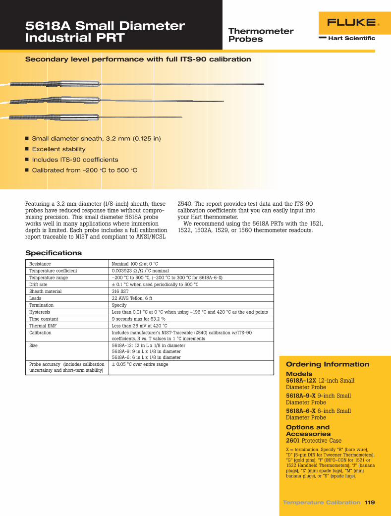
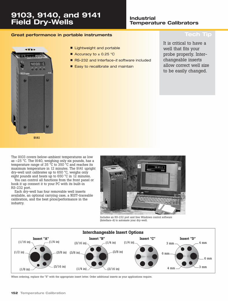
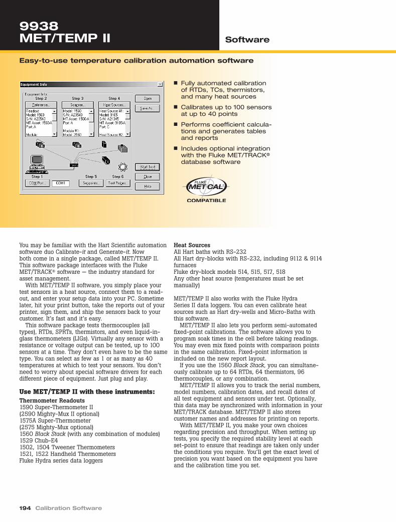
On the cover:
Wire wound resistors made in our Everett, WA facility arefound in Fluke Corporation’s most precise calibrators, references and standards. Constructed of one of two special alloys with offsetting temperature coefficients, theyare individually characterized, hermetically sealed, preciselymatched, then installed in sets to eliminate resistancechanges over operating temperature ranges. The benefit of this painstaking process? Outstanding performance andstability characteristics. In a word: confidence.
2162262_FPM cover.qxd 11/12/04 4:28 PM Page 3
riešenia na presné meranie www.elso.sk/Fluke-Calibration
Elso Philips Service, Trenčín
Josephson arrays in US and Germany. Fluke is onlyone of a handful of commercial organizations oper-ating Josephson Array standards to represent thevolt in their metrology operations. Fluke maintainstwo J-arrays, one at its corporate headquarters inEverett, Washington in the USA, and one in itsstandards laboratory in Kassell, Germany.
Fluke European Sales and Service Headquarters, Eindhoven, The Netherlands
UKAS-accredited temperature lab at Fluke Precision Measurement Ltd (formerlyWavetek-Datron), Norwich, United Kingdom
Fluke Hart Scientific Temperature Calibration Headquarters, American Fork, Utah, U.S.A.
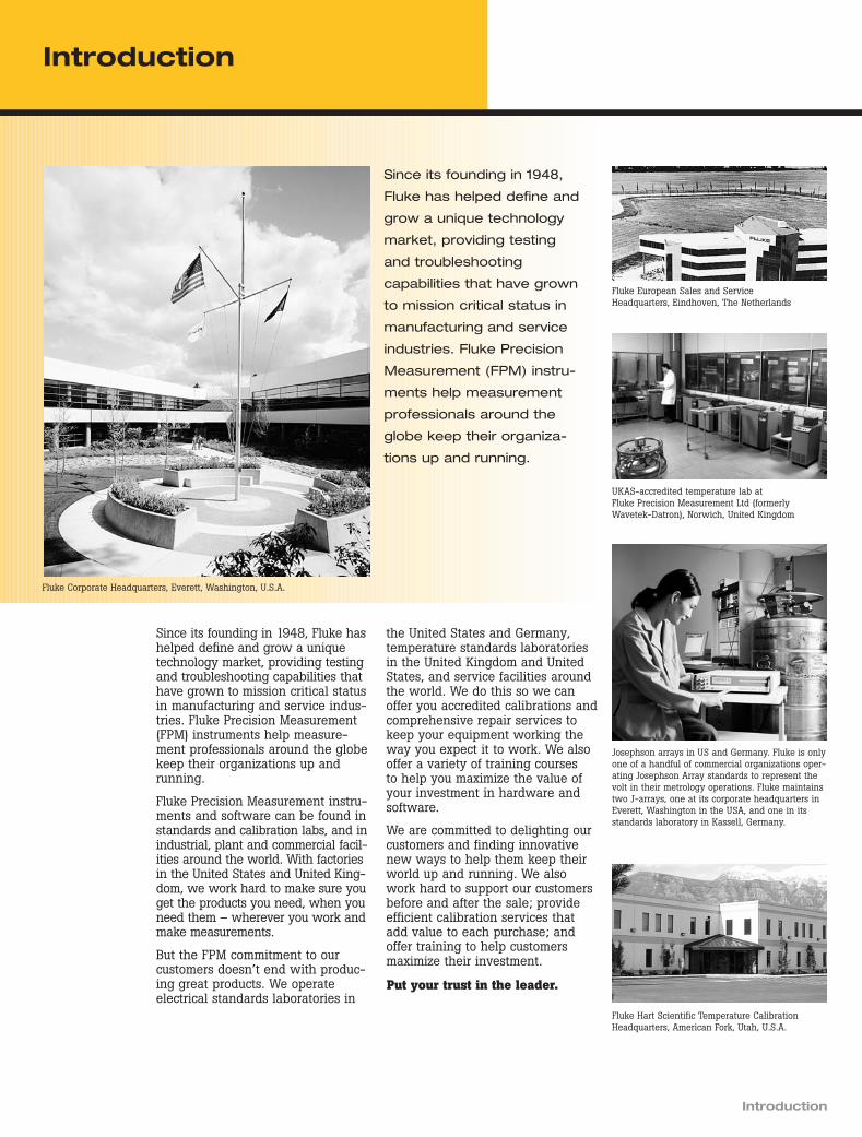
Since its founding in 1948, Fluke hashelped define and grow a uniquetechnology market, providing testingand troubleshooting capabilities thathave grown to mission critical statusin manufacturing and service indus-tries. Fluke Precision Measurement(FPM) instruments help measure-ment professionals around the globekeep their organizations up andrunning.
Fluke Precision Measurement instru-ments and software can be found instandards and calibration labs, and inindustrial, plant and commercial facil-ities around the world. With factoriesin the United States and United King-dom, we work hard to make sure youget the products you need, when youneed them – wherever you work andmake measurements.
But the FPM commitment to ourcustomers doesn’t end with produc-ing great products. We operateelectrical standards laboratories in
the United States and Germany,temperature standards laboratoriesin the United Kingdom and UnitedStates, and service facilities aroundthe world. We do this so we canoffer you accredited calibrations andcomprehensive repair services tokeep your equipment working theway you expect it to work. We alsooffer a variety of training courses to help you maximize the value ofyour investment in hardware andsoftware.
We are committed to delighting ourcustomers and finding innovativenew ways to help them keep theirworld up and running. We alsowork hard to support our customersbefore and after the sale; provideefficient calibration services thatadd value to each purchase; andoffer training to help customersmaximize their investment.
Put your trust in the leader.
Introduction_TOC.qxd 11/12/04 4:23 PM Page 1
riešenia na presné meranie www.elso.sk/Fluke-Calibration
riešenia na presné meranie www.elso.sk/Fluke-Calibration
Elso Philips Service, Trenčín
8508A Reference Multimeter Precision Multimeters
Tech Tip
4 Electrical Calibration
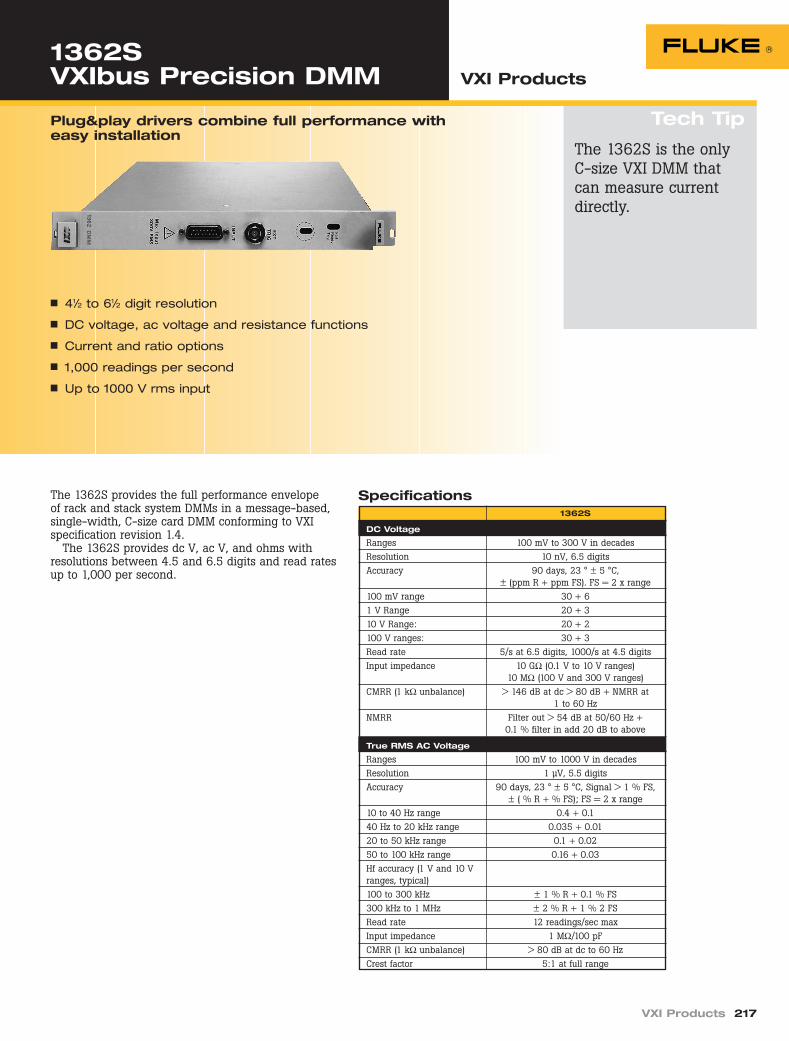
Reference standard accuracy and stability, in one functionally versatile, easy to use solution
n 8.5 digit resolution
n True Ohms measurement
n 20 Amp current measurement
n Reference-standard accuracy andstability
The 8508A Reference Multimeter is designed specifi-cally to address the measurement challenges faced bymetrologists. Not only does it provide the performancerequired for complex measurement tasks, it is alsoextremely easy to use. Moreover, it is specified in away that lets users really understand the uncertaintiesof the measurements they make.
Accuracy and stability The 8508A features 8.5 digit resolution, exceptionallinearity and extremely low noise and stability, producing superior accuracy specifications as low as 3 ppm over one year. But measurements need to berepeatable and the 8508A delivers that as well, with24-hour stability as low as 0.5 ppm and a 20-minutestability of 0.16 ppm. This stability is maintained over awide operating temperature range and achieved with-out requiring routine auto-cal or self-calibration, whichcan compromise measurement traceability and history.
Functional and versatile The Fluke 8508A lets you handle a wide range ofapplications and achieve your measurement require-ments with a single instrument, thus saving time andmoney. In addition to ac and dc voltage, ac and dccurrent, resistance and frequency, the 8508A alsoincludes a host of other features designed to increasethe range of measurements you can make. True Ohms
measurement using current reversal techniqueimproves the accuracy of your resistance measure-ments. The precision SPRT and PRT temperaturereadout extends the 8508A’s functionality intoadvanced temperature metrology. The Lo CurrentOhms feature reduces measurement errors due to self-heating within the device being measured. A dual input channel ratio feature, under GPIB control,enables the 8508A/01 to be used as a simple, fast,automated transfer standard. High current measure-ment — up to 20 A — extends the operational range toaddress your multi-product calibrator workload. Up to 200 V compliance on resistance ranges gives yougreater scope to measure high resistances with greateraccuracy.
Easy to use A clear control structure with Dual Paramatrix™ LCDdisplays and context sensitive menus provides a transparent, logical and intuitive interface that makesthe 8508A easy to use. The menu structures have beendesigned especially for metrology applications, so youcan focus on getting the best possible measurementswithout needing to work through complex sequentialor multi-instrument setups, or repeatedly referencesupporting documentation. To make sure that totaluncertainties of measurements are made clear, Flukepublishes 8508A uncertainties in both relative andabsolute terms. For full and comprehensive specifica-tions, refer to the extended specification data sheetavailable at www.fluke.com.
The 8508A has themeasurement functions,accuracy and stabilityof many metrologygrade instruments. Seethe application note,“Maximizing your refer-ence multimeter, mini-mizing measurementuncertainties” on theweb at www.fluke.com(Literature code 2090893)
n Versatile: replaces multiple laboratory reference standards
n Dual channel ratio provides simpleyet fast measurement transfer
n MET/CAL automation
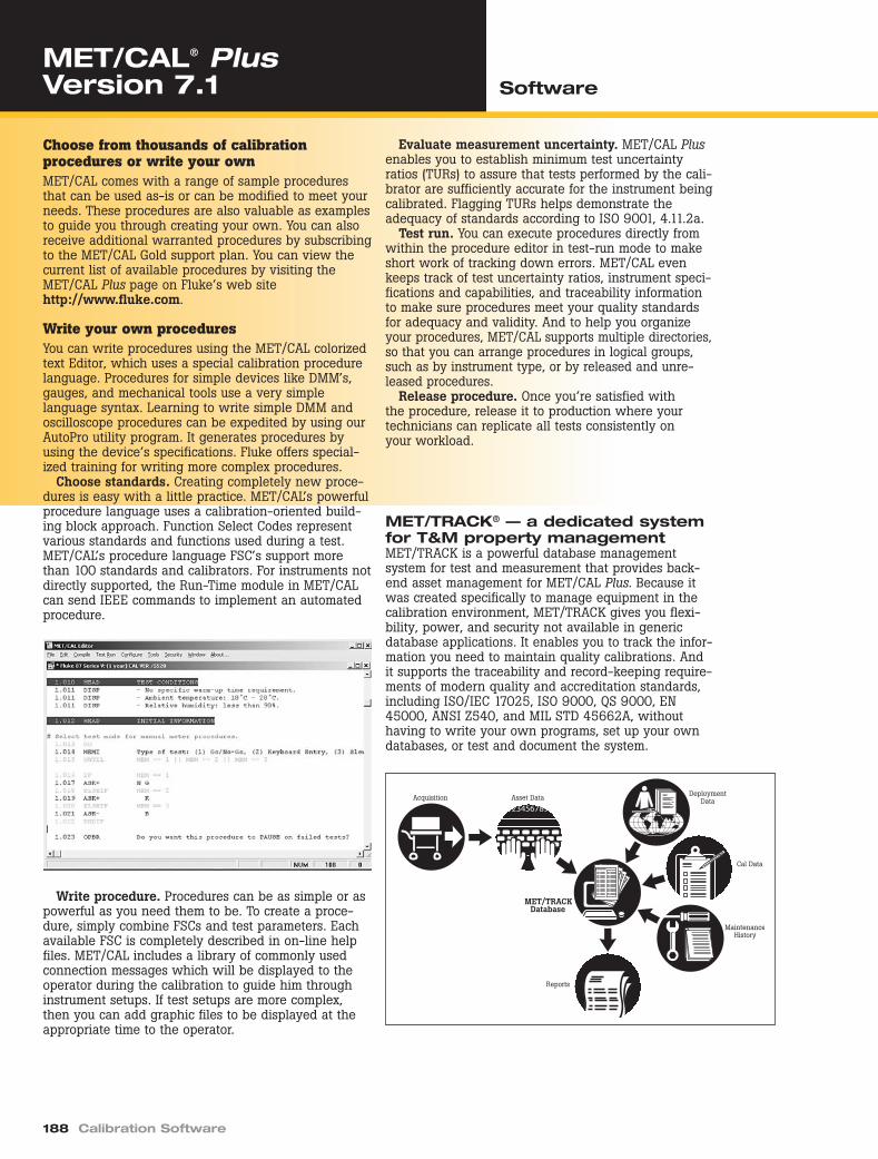
Precision Multimeters.qxd 11/11/04 2:59 PM Page 4
riešenia na presné meranie www.elso.sk/Fluke-Calibration
Notes:[1] Specifications apply for max resolution in each function, normal mode.[2] Assumes 4-hour warm-up period.[3] Input zero or offset null required whenever the temperature moves more than
± 1 °C from the temperature at which the previous null/zero was performed.[4] TCal – Ambient calibration temperatures.
Precision Multimeters.qxd 11/11/04 2:59 PM Page 5
riešenia na presné meranie www.elso.sk/Fluke-Calibration
10 k to 30 k 115 + 50 240 + 50 240 + 50 250 + 50 265 + 5030 k to 100 k 270 + 250 600 + 250 600 + 250 615 + 250 700 + 250
Notes:[1] Specifications apply for max resolution in each function, normal mode.[2] Assumes 4-hour warm-up period.[3] Input zero or offset null required whenever the temperature moves more than ± 1 °C from the temperature at which the previous null/zero was
performed.[4] TCal – Ambient calibration temperatures.[5] Integration time > 1 power line cycle.[6] Valid for signals > 1 % full scale, transfer mode on. Signal must be dc coupled < 40 Hz. Readings invalid with transfer mode on and 1 Hz filter
selected when using internal trigger mode.[7] Max Volt.Hertz 3 x 10⁷.[8] > 300 V, < 10 kHz add: ± 0.0004 (R-300)2 ppm
[9] Typical below 10 Hz for ac V, below 10 Hz, and above 10 kHz for ac I and above 2 GΩ for resistance.
Precision Multimeters.qxd 11/11/04 2:59 PM Page 6
riešenia na presné meranie www.elso.sk/Fluke-Calibration
Elso Philips Service, Trenčín
Electrical Calibration 7
AC CurrentAC Current [1] [2] [6] [9]
Uncertainty Relative to Cal Stds Absolute Uncertainties [9]
± (ppm Reading + ppm Range) [4]
Frequency 24 hour 90 day 365 day 365 day 365 dayRange Full Scale (Hz) TCal ± 1 °C TCal ± 1 °C TCal ± 1 °C TCal ± 1 °C TCal ± 5 °C
95 % Confidence Level
200 µA, 199.999 9 1 to 10 200 + 100 250 + 100 250 + 100 290 + 100 310 + 1002 mA, 1.999 999 10 to 10 k 200 + 100 250 + 100 250 + 100 280 + 100 300 + 10020 mA 19.999 99 10 k to 30 k 500 + 100 600 + 100 600 + 100 650 + 100 710 + 100
30 k to 100 k 0.35 % + 100 0.4 % + 100 0.4 % + 100 0.4 % + 100 0.4 % + 100200 mA 199.999 9 1 to 10 200 + 100 250 + 100 250 + 100 290 + 100 310 + 100
10 to 10 k 200 + 100 250 + 100 250 + 100 250 + 100 290 + 10010 k to 30 k 500 + 100 600 + 100 600 + 100 600 + 100 625 + 100
2 A 1.999 999 10 to 2 k 500 + 100 600 + 100 600 + 100 600 + 100 620 + 1002 k to 10 k 600 + 100 700 + 100 700 + 100 700 + 100 725 + 100
10 k to 30 k 0.25 % + 100 0.3 % + 100 0.3 % + 100 0.3 % + 100 0.3 % + 10020 A 19.999 99 10 to 2 k 700 + 100 800 + 100 800 + 100 800 + 100 820 + 100
2 k to 10 k 0.2 % + 100 0.25 % + 100 0.25 % + 100 0.25 % + 100 0.25 % + 10099 % Confidence Level
200 µA, 199.999 9 1 to 10 250 + 120 300 + 120 300 + 120 380 + 120 400 + 1202 mA, 1.999 999 10 to 10 k 250 + 120 300 + 120 300 + 120 340 + 120 370 + 12020 mA 19.999 99 10 k to 30 k 600 + 120 700 + 120 700 + 120 775 + 120 800 + 120
30 k to 100 k 0.35 % + 120 0.4 % + 120 0.4 % + 120 0.4 % + 120 0.4 % + 120200 mA 199.999 9 1 to 10 250 + 120 300 + 120 300 + 120 380 + 120 400 + 120
10 to 10 k 250 + 120 300 + 120 300 + 120 305 + 120 360 + 12010 k to 30 k 600 + 120 700 + 120 700 + 120 700 + 120 740 + 120
2 A 1.999 999 10 to 2 k 600 + 120 700 + 120 700 + 120 705 + 120 725 + 1202 k to 10 k 700 + 120 800 + 120 800 + 120 815 + 120 860 + 120
10 k to 30 k 0.25 % + 120 0.3 % + 120 0.3 % + 120 0.3 % + 120 0.3 % + 12020 A 19.999 99 10 to 2 k 800 + 120 900 + 120 900 + 120 900 + 120 920 + 120
2 k to 10 k 0.2 % + 120 0.25 % + 120 0.25 % + 120 0.25 % + 120 0.25 % + 120
Notes:[1] Specifications apply for max resolution in each function, normal mode.[2] Assumes 4-hour warm-up period.[3] Input zero or offset null required whenever the temperature moves more than ± 1 °C from the temperature at which the previous null/zero was
performed.[4] TCal – Ambient calibration temperatures.[5] Integration time > 1 power line cycle.[6] Valid for signals > 1 % full scale, transfer mode on. Signal must be dc coupled < 40 Hz. Readings invalid with transfer mode on and 1 Hz filter
selected when using internal trigger mode.[7] Max Volt.Hertz 3 x 10⁷.[8] > 300 V, < 10 kHz add: ± 0.0004 (R-300)2 ppm
Notes:[1] Specifications apply for max resolution in each function, normal mode.[2] Assumes 4-hour warm-up period.[3] Input zero or offset null required whenever the temperature moves more than ± 1 °C from the temperature at which the previous null/zero was
performed.[4] TCal – Ambient calibration temperatures.[9] Typical below 10 Hz for ac V, below 10 Hz, and above 10 kHz for ac I and above 2 GΩ for resistance.[10] Tru Ohms mode available on 2 Ω to 20 kΩ ranges. Read rate reduced in Tru Ohms mode. Specification for Tru Ohms same as corresponding
normal or lo current range.
Precision Multimeters.qxd 11/11/04 2:59 PM Page 8
riešenia na presné meranie www.elso.sk/Fluke-Calibration
Elso Philips Service, Trenčín
Electrical Calibration 9
ResistanceResistance – Normal Mode (Secondary Specifications) [1] [2] [3] [10]
Temperature CoefficientTransfer Uncertainty
15 °C to 30 °C5 °C to 15 °C
Measurement 20 mins ± 1 °C 30 °C to 40 °CRange Current ± (ppm Reading + ppm Range) ± ppm Reading/°C
Type True 4-wire with Ohms guard, 2-wire selectableRatio accuracy Range to Range: ± (Net Front Input Accuracy + Net Rear Input Accuracy)
Within Range: Apply 24 hour or 20 minute Transfer Uncertainty specifications
Notes:[1] Specifications apply for max resolution in each function, normal mode.[2] Assumes 4-hour warm-up period.[3] Input zero or offset null required whenever the temperature moves more than ± 1 °C from the temperature at which the previous null/zero was
performed.[9] Typical below 10 Hz for ac V, below 10 Hz, and above 10 kHz for ac I and above 2 GΩ for resistance.[10] Tru Ohms mode available on 2 Ω to 20 kΩ ranges. Read rate reduced in Tru Ohms mode. Specification for Tru Ohms same as corresponding
normal or lo current range.
Precision Multimeters.qxd 11/11/04 2:59 PM Page 9
riešenia na presné meranie www.elso.sk/Fluke-Calibration
Elso Philips Service, Trenčín
8508A Reference Multimeter Precision Multimeters
10 Electrical Calibration
General Specifications
Power115 V Setting: 100 V to 120 V rms ± 10 %230 V Setting: 200 V to 240 V rms± 10 %Frequency: 47 Hz to 63 HzConsumption: < 80 VA
DimensionsHeight: 88 mm (3.5 in)Width: 427 mm (16.8 in)Depth: 487 mm (19.2 in)Weight: 11.5 kg (25.5 lbs)
Environment temperatureOperating: 0 °C to 50 °CSpecified Operation: 5 °C to 40 °CCalibration (TCal): 20 °C to 25 °CFactory Cal Temp: 23 °CStorage: –20 °C to 70 °CWarm Up: 4 hours to full uncertainty specification
Ordering InformationModels8508A Reference Multimeter8508A/01 Reference Multimeterwith Front and Rear 4 mm bindingposts and rear input ratio measurementOptions and Accessories8508A-LEAD Lead kit includingtwo pairs of 1 m six-wire ptfe cableterminated with gold flashedspades connectors and 4 mm plugs8508-7000K Calibration Kit includ-ing one 1 GΩ resistor, one screenedlead set, two 4-wire shorting P.C.B.and one carry case8508A-PRT 100 Ohm Platinum Resistance Thermometer8508A-SPRT Standard Platinum Resistance ThermometerY8508 Rack Mount KitY8508S Rack Mount Slide Kit1256990 NVLAP Accredited Calibration1883673 UKAS Accredited CalibrationSoftwareMET/CAL® Plus Automated Calibration Management Software
TemperatureTemperature Readout [1] [2] [3]
Resistance Absolute Resistance Typical Equivalent Temperature Measurement Uncertainty [12]
Measurement Uncertainty Nominal365 day Tcal ± 1 °C [4] Temperature Resistance Accuracy
Range ± (ppm Reading + mΩ) [11] Probe Type (°C) (Ω) ± (°C)95 % Confidence Level
200 to 1999.999 99 Ω 9.5 + 0.6 100 Ω PRT/SPRT 400 250 0.0025Type 4-wire current reversal resistance measurement with readout of equivalent temperature. 2-wire and 3-wire
selectable without current reversal. Refer to Resistance specifications for additional details.Temperature range –200 °C to 660 °C, readout also available in °F or K.Linearization ITS-90 or Callendar van Dusen. Entry and storage of coefficients and nominal resistance for up to 100 probes.Current source 1 mA
Relative humidity (non-condensing)Operating: 5 °C to 40 °C < 90 %Storage: 0 °C to 70 °C < 95 %
AutorangeRange Up:100 % of rangeRange Down: 9 % of range (18 % on 1000 V range)
Remote interfaceIEEE 488.2
WarrantyOne-year
CalibrationStandard Certificate: NPL-UK, traceable with dataOptional: NVLAP and UKAS, accredited with data
Notes:[1] Specifications apply for max resolution in each function, normal mode.[2] Assumes 4-hour warm-up period.[3] Input zero or offset null required whenever the temperature moves more than
± 1 °C from the temperature at which the previous null/zero was performed.[4] TCal – Ambient calibration temperatures.[11] Valid for 4-wire sensor.[12] Not including sensor uncertainty.
The broad range of Fluke cali-brators includes innovative solutions for wide workloadcoverage, dedicated oscilloscopecalibration, high accuracy, and temperature and pressurecalibration and measurement.
Of the multi-product calibra-tors, the 5520A calibrates thewidest workload, including 61⁄2 digit DMMs, oscilloscopes to300 MHz, 600 MHz and 1.1 GHz,pressure sensors, and muchmore. The 9100 Universal Cali-bration System features optionssupporting power metering andinsulation/continuity testers up to 2 GΩ.
For dedicated oscilloscopeworkloads, the 9500B offers thebenefits of hands-free, fully auto-mated, accurate calibration at aprice and performance level thatmeets a wide range of needs andbudgets, featuring leveled sinewaves to 6.4 GHz and edges to25 ps when used with the 9560 Active Head. The 5820Acalibrates oscilloscopes up to 2.1 GHz for upgradeable entry-level performance.
In the high-accuracy calibratorclass, the 5720A MultifunctionCalibrator offers excellent preci-sion, supporting 81⁄2 digit DMMs.
Rounding out the calibratorline is the 525A Temperature and Pressure Calibrator, whichprovides high accuracy andbroad functionality for tempera-ture and pressure instrumentcalibration.
DC_LF Cal.qxd 11/12/04 1:11 PM Page 11
riešenia na presné meranie www.elso.sk/Fluke-Calibration
Elso Philips Service, Trenčín
12 Electrical Calibration
CalibratorSelection Guide DC/LF Calibration
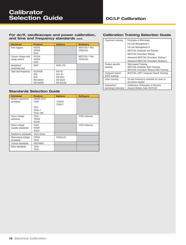
For dc/lf, oscilloscope and power calibration, and time and frequency standards cont.
Workload Product Options Software
Data loggers 5520A MET/CAL® Plus5500A 5500/Cal9100
Current clamps and 5520A MET/CAL® Plusclamp meters 5500A 5500/CAL
9100Insulation/ 9100 9100-135continuity testTime and frequency 910/910R 910-01
Advanced MET/CAL Procedure Writing IIProduct specific Web-based Trainingtraining MET/CAL Database Web Training
MET/CAL Procedure Writing Web TrainingComputer-based MET/CAL-CBT7 Computer Based Training(CBT) trainingOther training On-site training is available for most of
the above classesCalibration/ Calibration: Philosophy in Practice, metrology reference Second Edition, Item #937529
DC_LF Cal.qxd 11/12/04 1:11 PM Page 12
riešenia na presné meranie www.elso.sk/Fluke-Calibration
Elso Philips Service, Trenčín
n Widest workload coverage,including meters to 6.5digits and oscilloscopes to1.1 GHz (with options)
n Compliance with qualitystandards made easy
n Easy to use
n Versatile and flexible
n Portable and rugged
Calibration solutions that match your workload and budget
5520A Calibrator
5500A Calibrator
The standard Fluke 5500A Multi-Product Calibratorcalibrates digital and analog multimeters, thermometers(thermocouple and RTD), wattmeters, data loggers,current clamps, various types of recorders, panelmeters, process calibrators, power harmonics analyzersand many other similar measurement tools.
The 5520A builds on the 5500A’s capabilities,extending its workload coverage even further. Itsimproved accuracy, expanded ranges, and added features, including current to 20 A and pressure meas-urement, as well as its capability to calibrate 51⁄2 and61⁄2 digit multimeters, means the 5520A can covervirtually all your high-performance workload.
Options and accessories provide flexibilityand valueThe 5500A and 5520A offer several options to providetruly complete calibration solutions, including:n Options to calibrate oscilloscopes to 300 MHz,
600 MHz, or 1.1 GHz.n A power quality option for the 5520A that provides
additional calibration functions for power qualityinstruments, including traceability for highlydistorted sine wave signals.
n MET/CAL® Plus calibration and documentation software to help you automate calibration, pluscollect and report results.
n A complete range of accessories that enable you toconnect to virtually any instrument, measure relativehumidity, temperature and pressure, as well as cali-brate high current clamps and clamp meters and tostore and transport your calibrator.
Compliance with quality standards made easyWith standards such as ISO 17025, there is a lot moreto calibration than just making measurements. You alsohave documentation, control and reporting require-ments to meet.
Fluke’s optional Microsoft Windows®-basedMET/CAL® Plus software simplifies the documentationof your procedures, adequacy and traceability asrequired by ISO 17025 and other similar quality stan-dards. It also collects and reports calibration data andhelps consistently, quickly and efficiently calibrate awide variety of instruments. 5500/CAL is a specialversion of Fluke’s MET/CAL® Plus, designed to workwith the 5500A and 5520A. Because it controls instru-ments via an RS-232 (serial port), no IEEE interfacesare required.
For full and comprehensive specifications, refer tothe extended specification data sheet atwww.fluke.com.
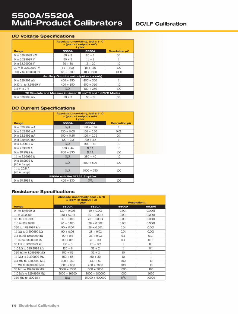
DC Voltage SpecificationsAbsolute Uncertainty, tcal ± 5 °C
± (ppm of output + mV)1 year
Range 5500A 5520A Resolution µV
0 to 329.9999 mV 60 + 3 20 + 1 0.10 to 3.299999 V 50 + 5 11 + 2 10 to 32.99999 V 50 + 50 12 + 20 1030 V to 329.9999 V 55 + 500 18 + 150 100100 V to 1000.000 V 55 + 1500 18 + 1500 1000
Auxiliary Output (dual output mode only)
0 to 329.999 mV 400 + 350 400 + 350 10.33 V to 3.29999 V 400 + 350 400 + 350 103.3 V to 7 V N/A 400 + 350 100
TC Simulate and Measure in Linear 10 mV/°C and 1 mV/°C Modes
0 to 329.999 mV 60 + 3 50 + 3 0.1
DC Current SpecificationsAbsolute Uncertainty, tcal ± 5 °C
± (ppm of output + mA)1 year
Range 5500A 5520A Resolution µA
0 to 329.999 mA N/A 150 + 0.02 10 to 3.29999 mA 130 + 0.05 100 + 0.05 0.010 to 32.9999 mA 100 + 0.25 100 + 0.25 0.10 to 329.999 mA 100 + 3.3 100 + 2.5 10 to 1.09999 A N/A 200 + 40 100 to 2.19999 A 300 + 44 N / A 100 to 10.9999 A 600 + 330 N / A 1001.1 to 2.99999 A N/A 380 + 40 100 to 10.9999 A(20 A Range) N/A 500 + 500 100
11 to 20.5 A(20 A Range) N/A 1000 + 750 100
5500A with the 5725A Amplifier
0 to 10.9999 A 400 + 330 N/A 100
DC_LF Cal.qxd 11/12/04 1:11 PM Page 14
riešenia na presné meranie www.elso.sk/Fluke-Calibration
Elso Philips Service, Trenčín
Electrical Calibration 15
AC Voltage (Sine Wave) SpecificationsAbsolute Uncertainty, tcal ± 5 °C
± (% of output + µV)1 year
Range Frequency 5500A 5520A Resolution
1.0 mV to 32.999 mV 10 Hz to 45 Hz 0.35 + 20 .08 + 6 1 µV45 Hz to 10 kHz 0.15 + 20 .015 + 610 kHz to 20 kHz 0.2 + 20 .02 + 620 kHz to 50 kHz 0.25 + 20 .1 + 650 kHz to 100 kHz 0.35 + 33 .35 + 12100 kHz to 500 kHz 1 + 60 .8 + 50
33 mV to 329.999 mV 10 Hz to 45 Hz 0.25 + 50 .05 + 8 1 µV45 Hz to 10 kHz 0.05 + 20 .0145 + 810 kHz to 20 kHz 0.1 + 20 .016 + 820 kHz to 50 kHz 0.16 + 40 .035 + 850 kHz to 100 kHz 0.24 + 170 .08 + 32100 kHz to 500 kHz 0.7 + 333 .2 + 70
0.33 V to 3.29999 V 10 Hz to 45 Hz 0.15 + 250 .03 + 50 10 µV45 Hz to 10 kHz 0.03 + 60 .015 + 6010 kHz to 20 kHz 0.08 + 60 .019 + 6020 kHz to 50 kHz 0.14 + 300 .03 + 5050 kHz to 100 kHz 0.24 + 1700 .07 + 125100 kHz to 500 kHz 0.5 + 3300 .24 + 600
3.3 V to 32.9999 V 10 Hz to 45 Hz 0.15 + 2500 .03 + 650 100 µV45 Hz to 10 kHz 0.04 + 600 .015 + 60010 kHz to 20 kHz 0.08 + 2600 .024 + 60020 kHz to 50 kHz 0.19 + 5000 .035 + 60050 kHz to 100 kHz 0.24 + 17000 .09 + 1600
33 V to 329.999 V 45 Hz to 1 kHz 0.05 + 6600 .019 + 2000 1 mV1 kHz to 10 kHz 0.08 + 15000 .02 + 600010 kHz to 20 kHz 0.09 + 33000 .025 + 600020 kHz to 50 kHz N/A .03 + 600050 kHz to 100 kHz N/A .2 + 50000
330 V to 1020 V 45 Hz to 1 kHz 0.05 + 80000 .03 + 10000 10 mV1 kHz to 5 kHz 0.20 + 100000 .025 + 100005 kHz to 10 kHz 0.20 + 500000 .03 + 10000
5500A with the 5725A Amplifier100 to 1020 V 45 Hz to 1 kHz 0.05 + 80000 N/A 10 mV
1 kHz to 20 kHz 0.08 + 100000 N/A20 kHz to 30 kHz 0.10 + 100000 N/A
100 to 750 V 30 kHz to 100 kHz 0.5 + 500000 N/AAUX (Auxiliary Output) [dual output mode only]
10 mV to 329.999 mV 10 Hz to 20 Hz 0.2 + 370 0.2 + 370 1 µV20 Hz to 45 Hz 0.1 + 370 0.1 + 37045 Hz to 1 kHz 0.1 + 370 0.1 + 3701 kHz to 5 kHz 0.2 + 450 0.2 + 4505 kHz to 10 kHz 0.4 + 450 0.4 + 45010 kHz to 30 kHz N/A 5.0 + 900
0.33 V to 3.29999 V 10 Hz to 20 Hz 0.2 + 450 0.2 + 450 10 µV20 Hz to 45 Hz 0.1 + 450 0.1 + 45045 Hz to 1 kHz 0.09 + 450 0.09 + 4501 kHz to 5 kHz 0.2 + 1400 0.2 + 14005 kHz to 10 kHz 0.4 + 1400 0.4 + 140010 kHz to 30 kHz N/A 5.0 + 2800
3.3 V to 5 V 10 Hz to 20 Hz N/A 0.2 + 450 100 µV20 Hz to 45 Hz N/A 0.1 + 45045 Hz to 1 kHz N/A 0.09 + 4501 kHz to 5 kHz N/A 0.2 + 1400
5 kHz to 10 kHz N/A 0.4 + 1400
DC_LF Cal.qxd 11/12/04 1:11 PM Page 15
riešenia na presné meranie www.elso.sk/Fluke-Calibration
Pt 395, 100 Ω –200 to –80 0.05–80 to 0 0.050 to 100 0.07
100 to 300 0.09300 to 400 0.10400 to 630 0.12630 to 800 0.23
Pt 3926, 100 Ω –200 to –80 0.05–80 to 0 0.050 to 100 0.07
100 to 300 0.09300 to 400 0.10400 to 630 0.12
Pt 3916, 100 Ω –200 to –190 0.25–190 to –80 0.04
–80 to 0 0.050 to 100 0.06
100 to 260 0.07260 to 300 0.08300 to 400 0.09400 to 600 0.10600 to 630 0.23
Pt 385, 200 Ω –200 to –80 0.04–80 to 0 0.040 to 100 0.04
100 to 260 0.05260 to 300 0.12300 to 400 0.13400 to 600 0.14600 to 630 0.16
Pt 385, 500 Ω –200 to –80 0.04–80 to 0 0.050 to 100 0.05
100 to 260 0.06260 to 300 0.08300 to 400 0.08400 to 600 0.09600 to 630 0.11
Pt 385, 1000 Ω –200 to –80 0.03–80 to 0 0.030 to 100 0.04
100 to 260 0.05260 to 300 0.06300 to 400 0.07400 to 600 0.07600 to 630 0.23
PtNi 385, 120 Ω –80 to 0 0.08(Ni120) 0 to 100 0.08
100 to 260 0.14Cu 427,10 Ω –100 to 260 0.3
n Resolution is 0.003 °C.n Temperature standard ITS-90 or
IPTS-68 is selectable.
DC Power Specification Summary
Absolute Uncertainty, tcal ± 5 °CVoltage Current ± (% of watts output)Range Range 1 year
5520A Calibrator33 mV to 0.33 mA to1020 V 329.99 mA 0.023 %
0.33 A to2.9999 A 0.022 %
3 A to 20.5 A 0.07 %5500A Calibrator
3.3 to 8.999 mA 0.04 %9 to 32.999 mA 0.03 %33 to 89.99 mA 0.04 %
90 to 329.99 mA 0.03 %0.33 to 0.8999 A 0.08 %0.9 to 2.1999 A 0.06 %2.2 to 4.4999 A 0.12 %
4.5 to 11 A 0.09 %5500A Calibrator with
5725A Current Amplifier1.5 to 4.4999 A 0.10 %
4.5 to 11 A 0.08 %
DC_LF Cal.qxd 11/12/04 1:11 PM Page 18
riešenia na presné meranie www.elso.sk/Fluke-Calibration
Elso Philips Service, Trenčín
Electrical Calibration 19
Note: Other frequency and phase/power factor conditions can applyand the power specifications will change accordingly. For additionalspecification information refer to the Extended Specifications datasheet and the instrument manual.
AC Power Specification Summary,shown for a frequency range of (45 Hz to 65 Hz) with a PF=1
Absolute Uncertainty, tcal ± 5 °C, ± (% of watts output) 1 year
Phase Specifications1-Year Absolute Uncertainty, tcal ± 5 °C, (∆ °)
Model 10 Hz to 65 Hz 65 Hz to 500 Hz 500 Hz to 1 kHz 1 kHz to 5 kHz 5 kHz to 10 kHz 10 kHz to 30 kHz
0.01 Hz to 119.99 Hz 0.01 Hz 25 ppm120.0 Hz to 1199.9 Hz 0.1 Hz ± 1 mHz1.200 kHz to 11.999 kHz 1.0 Hz 2.5 ppm12.00 kHz to 119.99 kHz 10 Hz 25 ppm ± 5 µHz120.0 kHz to 1199.9 kHz 100 Hz ± 15 mHz1.200 MHz to 2.000 MHz 1 kHz
Frequency Specifications1-Year Absolute Uncertainty, tcal ± 5 °
5500A 5725A Current Calibrator Voltage Range Voltage Range Amplifier
33 to 330 mV 100 to329.999 mV to 1020 V 1020 V
5500A Calibrator3.3 to8.999 mA 0.40 % 0.25 % 0.25 %
9 to32.999 mA 0.25 % 0.15 % 0.15 %
33 to89.99 mA 0.35 % 0.25 % 0.25 %
90 to329.99 mA 0.25 % 0.15 % 0.15 %
0.33 to 0.8999 A 0.35 % 0.25 % 0.25 %
0.9 to 2.1999 A 0.25 % 0.15 % 0.15 %
2.2 to 4.4999 A 0.35 % 0.20 % 0.20 %
4.5 to 11 A 0.25 % 0.15 % 0.15 %5725A Amplifier
1.5 to 4.4999 A 0.35 % 0.20 %
4.5 to 11 A 0.25 % 0.15 %
Current 5520ARange Voltage Range
33 to 330 mV329.999 mV to 1020 V
5520A3.3 to 8.999 mA 0.14 % 0.12 %9 to 32.999 mA 0.10 % 0.08 %33 to 89.99 mA 0.14 % 0.12 %90 to 329.99 mA 0.10 % 0.08 %0.33 to 0.8999 A 0.13 % 0.11 %0.9 to 2.9999 A 0.11 % 0.09 %3.0 to 10.9999 A 0.13 % 0.12 %11 to 20.5 A 0.11 % 0.10 %
Oscilloscope calibrationFor specifications for the oscilloscope calibration options, pleaserefer to the oscilloscope calibration section of this catalog.
CalibrationStandard: NVLAP accredited certificate, traceable to NIST, includingmeasurement data.The oscilloscope calibration option’s calibration certificate in non-accredited, but is traceable to NIST with measurement data. Anaccredited scope cal option calibration is available. Contact Flukefor details.
DC_LF Cal.qxd 11/12/04 1:11 PM Page 19
riešenia na presné meranie www.elso.sk/Fluke-Calibration
For the following functions the detailed specifications can be foundin the Extended Specifications data sheet or the instrument manual.n Harmonics (2nd to 50th)n AC voltage sine wave extended bandwidth of .01 Hz to 2 MHzn AC voltage non-sine wave functions: Truncated sine wave,
Triangle wave, Square waven AC voltage, dc offsetn AC current sine wave extended bandwidth .01 Hz to 10 Hzn 5520 ac current (non-sine wave) specifications: Triangle wave,
Truncated sine wave, Square wave
Ordering InformationModels5520A High Performance Multi-Product Calibrator5520A/3 5520A Calibrator with300 MHz Oscilloscope CalibrationOption5520A/6 5520A Calibrator with600 MHz Oscilloscope CalibrationOption5520A/1 GHz 5520A Calibratorwith 1.1 GHz Oscilloscope Calibration Option5500A Multi-Product Calibrator5500A/3 5500A Calibrator with300 MHz Oscilloscope CalibrationOption5500A/6 5500A Calibrator with600 MHz Oscilloscope CalibrationOptionOptions and Accessories 5500A-SC300 300 MHz Oscilloscope Calibration Option5500A-SC600 600 MHz/300 psOscilloscope Calibration Option5520A-SC1100 1.1 GHz Oscilloscope Calibration Option(5520A only)5500A/LEADS Comprehensive Test Lead Kit5520A-525A/LEADS Test LeadSet5800A/TDP 125 ps Tunnel DiodePulser5500A/COIL 50-Turn Coil5500A/CASE Transit Case with Wheels5725A Amplifier (5500A only)5500A/HNDL Side Handle700PCK Pressure Calibration KitY5537 Rack Mount Kit(5500A/5520A)Y5735 Rack Mount Kit (5725A)SoftwareMET/CAL® Plus Automated Calibration Management Software5500/CAL Automated CalibrationSoftware (RS-232 only)
General SpecificationsWarmup timeTwice the time since last warmedup, to a maximum of 30 minutes
Settling timeLess than 5 seconds for all func-tions and ranges except as noted
Standard interfacesIEEE-488 (GPIB), RS-232, 5725A(5500A only)
Temperature performanceOperating: 0 °C to 50 °CCalibration (tcal): 15 °C to 35 °CStorage: –20 °C to 70 °C
Temperature coefficient5500A: Temperature coefficient fortemperatures outside tcal ± 5 °C is10 % of the 90-day specification (or1-year, as applicable) per °C5520A: Temperature coefficient fortemperatures outside tcal ±5 °C is10 % of the stated specification per°C for temperatures in the range of0 °C to 35 °C. Above 35 °C, thetemperature coefficient is 20% ofthe stated specification per °C.
Relative humidityOperating: < 80 % to 30 °C, < 70 %to 40 °C, < 40 % to 50 °CStorage: < 95 %, noncondensingNote: After long periods of storage at highhumidity, a drying out period (with the poweron) of at least one week may be required
AltitudeOperating: 3,050 m (10,000 ft)maximumNon-operating: 12,200 m (40,000 ft) maximum
SafetyDesigned to comply with IEC 1010-1 (1992-1); ANSI/ISA-S82.01-1994;CAN/CSA-C22.2 No. 1010.1-92
Analog low isolation20 V
EMC5520A: Designed to comply withIEC 61326-1/19975500A: Designed to comply withFCC Rules Part 15
Line powerLine Voltage (selectable): 100 V,120 V, 220 V, 240 VLine Frequency: 47 to 63 HzLine Voltage Variation: ± 10 %about line voltage settingNote: For optimal 5520A performance at full dual outputs(e.g. 1000 V, 20 A), choose a linevoltage setting that is ± 7.5 % fromnominal
Power consumption5520A: 600 VA5500A: 300 VA
DimensionsHeight:17.8 cm (7 in), standard rackincrement, plus 1.5 cm (0.6 in) forfeet on bottom of unitWidth: 43.2 cm (17 in), standardrack widthDepth: 47.3 cm (18.6 in) overall
Weight (without options)5520A: 22 kg (49 lb)5500A: 20 kg (44 lb)
Absolute uncertainty definition5500A and 5520A uncertaintyspecifications include stability,temperature coefficient, linearity,line and load regulation and thetraceability of the external standards used for calibration.You do not need to add anything to determinethe total uncertainty of your calibrator for thetemperature range indicated.
Specification confidenceinterval> 99 %
DC_LF Cal.qxd 11/12/04 1:11 PM Page 20
riešenia na presné meranie www.elso.sk/Fluke-Calibration
Elso Philips Service, Trenčín
9100 Universal Calibration System DC/LF Calibration
Tech Tip
Electrical Calibration 21
Versatile entry-level performance
n Unique insulation and continuity meter calibration
n AC current to 30 KHz
n AC/DC current to 20 amps
n Extensive range of availablecalibration procedures
The affordable and versatile 9100 is designed to cali-brate an impressive range of portable meter workloadincluding: handheld multimeters, bench multimeters,analog meters, panel meters, clamp meters, powermeters, harmonic analyzers, oscilloscopes, ScopeMeter®
Test Tools, insulation/continuity meters, counters, electronic thermometers, chart recorders, oscillographrecorders, XY recorders, and data loggers. With itseasy-to-use front panel featuring a clear and informa-tive LCD display, and its unique procedure-driven calibration routines, the 9100 is not only a versatilecalibrator but also one that will increase calibrationthroughput significantly.
For full and comprehensive specifications, refer tothe extended specification data sheet atwww.fluke.com.
DC Voltage AccuracyVoltage Accuracy [1]
Output ± (% of Output + Floor) AbsolutePolarities 1 Year – Tcal ± °C [2] Resolution
000.000 mVto 320.000 mV 0.006 % + 4.16 µV 1 µV
0.32001 Vto 3.2000 V 0.006 % + 41.6 µV 10 µV
03.2001 Vto 32.0000 V 0.0065 % to 416 µV 100 µV
032.001 Vto 320.000 V 0.0065 % to 4.48 mV 1 mV
0320.01 Vto 1050.00 V 0.006 % to 19.95 mV 10 mV
[1] = For loads < 1 MΩ: add load regulation error.[2] Tcal = temperature at calibration. Factory calibration temperature = 23 °C
The lead mat suppliedwith the 9100 willautomatically optimizethe signal paths to the UUT.
DC_LF Cal.qxd 11/12/04 1:11 PM Page 21
riešenia na presné meranie www.elso.sk/Fluke-Calibration
9100 Universal Calibration System DC/LF Calibration
22 Electrical Calibration
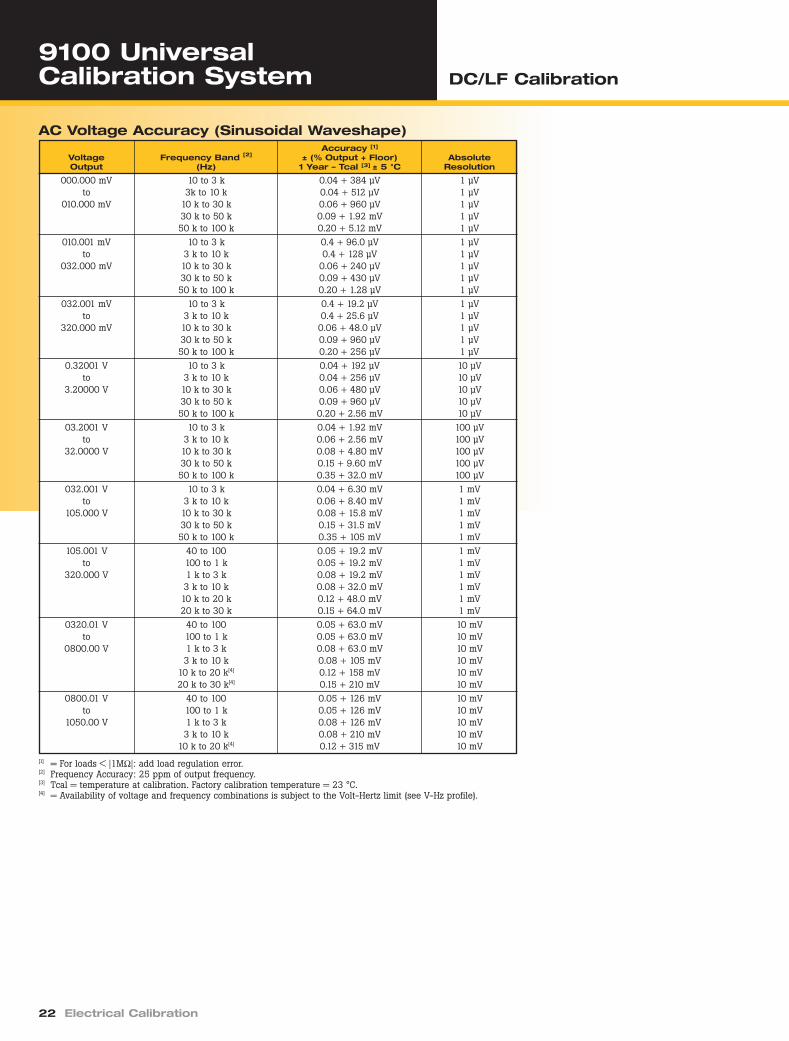
AC Voltage Accuracy (Sinusoidal Waveshape)Accuracy [1]
Voltage Frequency Band [2] ± (% Output + Floor) AbsoluteOutput (Hz) 1 Year – Tcal [3] ± 5 °C Resolution
000.000 mV 10 to 3 k 0.04 + 384 µV 1 µVto 3k to 10 k 0.04 + 512 µV 1 µV
010.000 mV 10 k to 30 k 0.06 + 960 µV 1 µV30 k to 50 k 0.09 + 1.92 mV 1 µV50 k to 100 k 0.20 + 5.12 mV 1 µV
010.001 mV 10 to 3 k 0.4 + 96.0 µV 1 µVto 3 k to 10 k 0.4 + 128 µV 1 µV
032.000 mV 10 k to 30 k 0.06 + 240 µV 1 µV30 k to 50 k 0.09 + 430 µV 1 µV50 k to 100 k 0.20 + 1.28 µV 1 µV
032.001 mV 10 to 3 k 0.4 + 19.2 µV 1 µVto 3 k to 10 k 0.4 + 25.6 µV 1 µV
320.000 mV 10 k to 30 k 0.06 + 48.0 µV 1 µV30 k to 50 k 0.09 + 960 µV 1 µV50 k to 100 k 0.20 + 256 µV 1 µV
0.32001 V 10 to 3 k 0.04 + 192 µV 10 µVto 3 k to 10 k 0.04 + 256 µV 10 µV
3.20000 V 10 k to 30 k 0.06 + 480 µV 10 µV30 k to 50 k 0.09 + 960 µV 10 µV50 k to 100 k 0.20 + 2.56 mV 10 µV
03.2001 V 10 to 3 k 0.04 + 1.92 mV 100 µVto 3 k to 10 k 0.06 + 2.56 mV 100 µV
32.0000 V 10 k to 30 k 0.08 + 4.80 mV 100 µV30 k to 50 k 0.15 + 9.60 mV 100 µV50 k to 100 k 0.35 + 32.0 mV 100 µV
032.001 V 10 to 3 k 0.04 + 6.30 mV 1 mVto 3 k to 10 k 0.06 + 8.40 mV 1 mV
105.000 V 10 k to 30 k 0.08 + 15.8 mV 1 mV30 k to 50 k 0.15 + 31.5 mV 1 mV50 k to 100 k 0.35 + 105 mV 1 mV
105.001 V 40 to 100 0.05 + 19.2 mV 1 mVto 100 to 1 k 0.05 + 19.2 mV 1 mV
320.000 V 1 k to 3 k 0.08 + 19.2 mV 1 mV3 k to 10 k 0.08 + 32.0 mV 1 mV10 k to 20 k 0.12 + 48.0 mV 1 mV20 k to 30 k 0.15 + 64.0 mV 1 mV
0320.01 V 40 to 100 0.05 + 63.0 mV 10 mVto 100 to 1 k 0.05 + 63.0 mV 10 mV
0800.00 V 1 k to 3 k 0.08 + 63.0 mV 10 mV3 k to 10 k 0.08 + 105 mV 10 mV
10 k to 20 k[4] 0.12 + 158 mV 10 mV20 k to 30 k[4] 0.15 + 210 mV 10 mV
0800.01 V 40 to 100 0.05 + 126 mV 10 mVto 100 to 1 k 0.05 + 126 mV 10 mV
1050.00 V 1 k to 3 k 0.08 + 126 mV 10 mV3 k to 10 k 0.08 + 210 mV 10 mV
10 k to 20 k[4] 0.12 + 315 mV 10 mV[1] = For loads < |1MΩ|: add load regulation error.[2] Frequency Accuracy: 25 ppm of output frequency.[3] Tcal = temperature at calibration. Factory calibration temperature = 23 °C.[4] = Availability of voltage and frequency combinations is subject to the Volt-Hertz limit (see V-Hz profile).
DC_LF Cal.qxd 11/12/04 1:11 PM Page 22
riešenia na presné meranie www.elso.sk/Fluke-Calibration
Elso Philips Service, Trenčín
Electrical Calibration 23
AC Current Accuracy (Sinusoidal Waveshape)Accuracy [1]
Frequency Band [2] ± (% Output + Floor)Current Output (Hz) 1 Year - Tcal [3] ± 5 °C Absolute Resolution
000.000 µA to 032.000 µA 10 to 3 k 0.07 + 900 nA 1 nA3 k to 10 k 0.10 + 1.8 µA 1 nA
10 k to 20 k 0.20 + 6.0 µA 1 nA20 k to 30 k 0.25 + 9.0 µA 1 nA
032.001 µA to 320.000 µA 10 to 3 k 0.07 + 300 nA 1 nA3 k to 10 k 0.10 + 600 nA 1 nA10 k to 20 k 0.20 + 2.0 µA 1 nA20 k to 30 k 0.25 + 3 µA 1 nA
0.32001 mA to 3.20000 mA 10 to 3 k 0.07 + 300 nA 10 nA3 k to 10 k 0.10 + 600 nA 10 nA10 k to 20 k 0.20 + 2.0 µA 10 nA20 k to 30 k 0.25 + 3.0 µA 10 nA
03.2001 mA to 32.0000 mA 10 to 3 k 0.07 + 3.2 µA 100 nA3 k to 10 k 0.10 + 6.4 µA 100 nA10 k to 20 k 0.20 + 12.8 µA 100 nA20 k to 30 k 0.25 + 22.4 µA 100 nA
032.001 mA to 320.000 mA 10 to 3 k 0.08 + 32.0 µA 1 µA3 k to 10 k 0.10 + 48.0 µA 1 µA10 k to 20 k 0.20 + 64.0 µA 1 µA20 k to 30 k 0.25 + 96.0 µA 1 µA
0.32001 A to 3.20000 A 10 to 3 k 0.10 + 480 µA 10 µA3 k to 10 k 0.25 + 2.56 mA 10 µA
03.2001 A to 10.5000 A 10 to 3 k 0.20 + 3.0 mA 100 µA3 k to 10 k 0.50 + 10.0 mA 100 µA
10.5001 A to 20.0000 A [4] 10 to 3 k 0.20 + 6.9 mA 100 µA3 k to 10 k 0.50 + 23.0 mA 100 µA
03.2001 A to 32.0000 A [5] 10 to 100 0.20 + 5.5 mA 100 µA100 to 440 0.78 + 27 mA 100 µA
032.001 A to 200.000 A [4][5] 10 to 100 0.21 + 90 mA 1 mA100 to 440 0.67 + 0.25 A 1 mA
016.001 A to 160.000 A [6] 10 to 100 0.20 + 28 mA 1 mA0160.01 A to 1000.00 A [4][6] 10 to 100 [8] 0.21 + 0.45 A 10 mA
[1] = Total uncertainty includes compliance errors for voltage 0.5 Vrms. Above 0.5 V, add appropriate compliance error, except for outputs marked [4] and [6].
[2 Frequency Accuracy: 25 ppm of output frequency.[3] Tcal = temperature at calibration. Factory calibration temperature = 23 °C.[4] = With output ‘ON’, maximum duty cycle of (> 0.525FS : 0.525FS) is (1 : 4). Continuous output > 0.525FS will
automatically reduce to < 0.525FS after 2 minutes.[5] = Accuracy at 9100 output terminals, option 200 10 turn coil connected. For the output from the coil,
add ± 0.2 % of output from coil for uncertainty of coil.[6] = Accuracy at 9100 output terminals, option 200 50 turn coil connected. For the output from the coil,
add ± 0.2 % of output from coil for uncertainty of coil.[7] = For frequencies < 40 Hz, compliance voltage is reduced by 0.5 Vrms.[8] = These coils have been designed for optimum accuracy and inductance for use with the Model 9100.
With some clamp meters, especially those using Hall effect, the increase in inductance due to the current clamp design will limit the obtainable 9100 Current/Hertz profile. In some cases, 1000 A cannot be reached at higher frequency.
DC Current AccuracyAccuracy
± (% of Output + Floor)Equivalent Current Output 1 Year – Tcal ± 5 °C [1] Absolute Resolution
000.000 µA to 320.000 µA 0.014 + 11 nA 1 nA0.32001 mA to 3.20000 mA 0.014 + 83 nA 10 nA03.2001 mA to 32.0000 mA 0.014 + 900 nA 100 nA032.001 mA to 320.000 mA 0.016 + 9.6 µA 1 µA0.32001 A to 3.20000 A 0.060 + 118 µA 10 µA03.2001 A to 10.5000 A 0.055 + 940 µA 100 µA10.5001 A to 20.0000 A [2] 0.055 + 4.50 mA 100 µA
[1] Tcal = temperature at calibration. Factory calibration temperature = 23 °C.[2] = With output ‘ON’, maximum duty cycle of (> 0.525FS : 0.525FS) is (1 : 4). Continuous output > 0.525FS will
automatically reduce to < 0.525FS after 2 Minutes.
DC_LF Cal.qxd 11/12/04 1:11 PM Page 23
riešenia na presné meranie www.elso.sk/Fluke-Calibration
Elso Philips Service, Trenčín
9100 Universal Calibration System DC/LF Calibration
24 Electrical Calibration
Frequency Function AccuracyAccuracy Accuracy
Frequency ± (ppm of Output Frequency) ± (ppm of Output Frequency) Mark/PeriodOutput 1 Year – Tcal ± 5 °C [1] Standard 5 Year – Tcal ± 5 °C [1] Option 100 Ratio (%)
0.5 Hz to 10.0 MHz 25.0 0.25 50[1] Tcal = temperature at calibration. Factory calibration temperature = 23 °C.
Conductance AccuracyAccuracy ±(% Output)
Conductance Output 1 Year – Tcal ± 5 °C [1] UUTi Low & High UUTi Super
2.5 nS to 25.0 nS 0.4025.0 nS to 250.0 nS 0.20250.0 nS to 2.5 µS 0.122.5 µS to 25.0 µS 0.0525.0 µS to 250. 0 µS 0.05250.0 µS to 2.5 mS 0.04
[1] Tcal = temperature at calibration. Factory calibration temperature = 23 °C.
[1] = Accuracy specifications apply both at the 9100 output terminals, and at the output leads of the Model 9105 lead set.[2] Tcal = temperature at calibration. Factory calibration temperature = 23 °C.
[1] Tcal = temperature at calibration. Factory calibration temperature = 23 °C.[2] = Valid for UUTi ≥ 200 µA. Below 200 µA: new floor = (200 µA ÷ Actual UUTi) x 20 mΩ.
DC_LF Cal.qxd 11/12/04 1:11 PM Page 24
riešenia na presné meranie www.elso.sk/Fluke-Calibration
Elso Philips Service, Trenčín
Electrical Calibration 25
Thermocouple Temperature AccuracyThermocouple Temperature Output Accuracy [1][2][3] (± °C)
Type (Screen Resolution Shown) 1 Year – Tcal ± 5 °C [4]
B 0500.0 °C to 0800.0 °C 0.550800.0 °C to 1000.0 °C 0.411000.0 °C to 1400.0 °C 0.341400.0 °C to 1820.0 °C 0.37
C 0000.0 °C to 0600.0 °C 0.290600.0 °C to 1000.0 °C 0.271000.0 °C to 1800.0 °C 0.401800.0 °C to 2320.0 °C 0.41
E –0250.0 °C to –0200.0 °C 0.45–0200.0 °C to –0100.0 °C 0.22–0100.0 °C to 0100.0 °C 0.170100.0 °C to 1000.0 °C 0.21
J –0210.0 °C to –0100.0 °C 0.25–0100.0 °C to 0800.0 °C 0.190800.0 °C to 1000.0 °C 0.211000.0 °C to 1200.0 °C 0.23
K –0250.0 °C to –0200.0 °C 0.57–0200.0 °C to –0100.0 °C 0.27–0100.0 °C to 0100.0 °C 0.190100.0 °C to 0600.0 °C 0.230600.0 °C to 1372.0 °C 0.27
L –0200.0 °C to –0050.0 °C 0.26–0050.0 °C to 0200.0 °C 0.180200.0 °C to 0700.0 °C 0.200700.0 °C to 0900.0 °C 0.23
N –0200.0 °C to –0100.0 °C 0.33–0100.0 °C to 0900.0 °C 0.230900.0 °C to 1100.0 °C 0.221100.0 °C to 1300.0 °C 0.24
R 0000.0 °C to 0100.0 °C 0.520100.0 °C to 0200.0 °C 0.400200.0 °C to 1600.0 °C 0.351600.0 °C to 1767 °C 0.28
S 0000.0 °C to 0200.0 °C 0.490200.0 °C to 1000.0 °C 0.371000.0 °C to 1400.0 °C 0.351400.0 °C to 1767.0 °C 0.36
T –0250.0 °C to –0200.0 °C 0.59–0200.0 °C to –0100.0 °C 0.27–0100.0 °C to 0000.0 °C 0.220000.0 °C to 0400.0 °C 0.17
[1] = Accuracy figures include CJC error.[2] = Compensated output determined from pre-defined tables based on:
IPTS-68 Reference Table NIST Monograph 125 for Types: B, E, J, K, R, S and T.ITS-90 Reference Table NIST Monograph 175 for Types: B, E, J, K, N, R, S and T.IPTS-68 Reference Table DIN 43710 for Type L.ITS-90 Reference Table DIN 43710 for Type L.
[3] = For loads < 1 MΩ add load regulation error.[4] Tcal = temperature at calibration. Factory calibration temperature = 23 °C.[5] = Types R & S adjusted above 1700 °C for IPTS-68 as per NIST monograph 175.
Other Thermocouple Output Specifications
Settling time to within 10 % of accuracy 0.08 sLoad regulation (200/RLOAD) % of outputMaximum capacitance 1000 pF
DC_LF Cal.qxd 11/12/04 1:11 PM Page 25
riešenia na presné meranie www.elso.sk/Fluke-Calibration
Elso Philips Service, Trenčín
9100 Universal Calibration System DC/LF Calibration
26 Electrical Calibration
RTD Temperature AccuracyAccuracy [1]: ± (% of Output + Floor)
1 Year – Tcal ± 5 °C [2]
Temperature Resistance at 0 °C = Resistance at 0 °C = Resistance at 0 °C =Output 10 Ω to 60 Ω 60 Ω to 1 kΩ 1 kΩ to 2 kΩ
–200 °C to –100 °C 0.00 + 0.225 °C 0.00 + 0.15 °C 0.00 + 0.12 °C–100 °C to 100 °C 0.00 + 0.15 °C 0.00 + 0.10 °C 0.00 + 0.08 °C100 °C to 630 °C 0.00 + 0.30 °C 0.00 + 0.20 °C 0.00 + 0.16 °C630 °C to 850 °C 0.00 + 0.45 °C 0.00 + 0.30 °C 0.00 + 0.24 °C
[1] = Accuracy figures apply to Output Temperature vs Resistance curves PT385 or PT392 and to Temperature Scales IPTS-68 or ITS-90 asselected by the user:PT385, IPTS-68 as per IEC751.PT392, IPTS-68 as per SAMA.PT385, ITS-90 as per IEC751 amendment 2.PT392, ITS-90 as per NIST monograph 175 corrections (90-68).
[2] Tcal = temperature at calibration. Factory calibration temperature = 23 °C.
Insulation Specifications (Option 135)Uncertainties are for 1 year, Tcal ± °C
Function Range Best Uncertainty
Insulation Resistance
Resistance 100 kΩ to 2 GΩ 0.1 %Voltage (measured) 0 to 1350 V 0.6 %Current (derived) 1 µA to 2.3 mA 1.5 %Continuity
Resistance 0 to 4 kΩ 0.035 %Voltage 0 to 10 VCurrent (derived) 100 µA to 350 mA 1.0 %
Power Option Specifications (Option PWR)Voltage Output Frequency Band (Hz) Output Phase Uncertainty
0.30000 V to 105.000 V 10 to 65 0.07 °65 to 1 k 0.07 + 0.001 x (f - 65 ) °
105.001 V to 750.000 V 45 to 65 0.16 °65 to 1 k 0.16 + 0.0037 x (5 - 65) °
Current Output Frequency Band (Hz) Output Phase Uncertainty
0.00000 A to 20.0000 A 10 to 65 0.08 °65 to 1 k 0.08 + 0.0008 x (f - 65) °
> 1 k 0.08 + 0.0012 x (f - 65) °03.2000 A to 1000.00 A 10 to 65 0.23 °
65 to 440 0.23 + 0.003 x (f - 65) °Auxiliary ChannelVoltage Output
Frequency Band (Hz) Output Phase Uncertainty
0.32 mV to 7.500 A 10 to 65 0.007 °65 to 1 k 0.07 + 0.001 x (f - 65) °
< 1 k 0.07 + 0.0015 x (f - 65) °
Oscilloscope calibrationFor specifications for the oscilloscope calibrationoptions, please refer to the oscilloscope calibrationsection of this catalog.
CalibrationA certificate traceable to NPL-UK, including measure-ment data, is supplied. For additional certificate types,contact your local representation.
DC_LF Cal.qxd 11/12/04 1:11 PM Page 26
riešenia na presné meranie www.elso.sk/Fluke-Calibration
Elso Philips Service, Trenčín
Electrical Calibration 27
Ordering InformationModels9100 Multifunction CalibrationWorkstationOptions and Accessories9100-600 600 MHz OscilloscopeCalibration Module9100-250 250 MHz OscilloscopeCalibration Module9100-200 10/50 Turn Coil9100-PWR Power Calibration9100-135 Insulation/ContinuityTest9100-100 High Stability CrystalRef.9100-90 Rack Mount Kit9500-65 Hard Transit Case(requires option 60)9100-60 Soft Carry CaseSoftwareMET/CAL® Plus Automated Calibration Management Software
General Specifications
Line power supplyVoltage (single I): 100 V/200 V/220 V/240 V selectable from rearpanelVariation: < +10 % nominal voltageLine Frequency: 48 Hz to 63 HzConsumption: 450 VA max 500 VAmax with Option 250Power Fuses: 220/240 V: T3, 15 AHBC, 250 V, IEC127100/120 V: T5, 0 A HBC, 250 V, IEC 127
DimensionsHeight: 3 UWidth: 427 mm (16.8 in)Depth: 460 mm (18.1 in)Weight: 18.5 kg (41 lbs)19 kg (42 lbs) with Option 250Safety: Designed to UL1244,IEC1010-1: Pollution degree 2;installation category II; Protectionclass I
Environmental conditionsTemperatureOperating: 5 °C to 40 °CTransit: –20 °C to 60 °C < 100 hrsStorage: 0 °C to 50 °CWarm-up Time: 20 minutesMax. relative humidity (non-condensing)Operating: + 5 °C to + 30 °C: < 90 %; + 30 °C to + 40 °C: <75 %Storage: 0 °C to + 50 °C: < 95 %AltitudeOperating: 0 to 2000 m (6.562 ft);Non-operating: 0 to 12,00 m(40,000 ft)Shock: MIL-T-28800, type III, class5, style EVibration: MIL-T-28800, type III,class 5, style EEnclosure: MIL-T-2880, type III,class 5, style EEMC: Designed to: Generic Emis-sions: EN50081; Generic Immunity:EN50082; FCC Rules part 15 sub-part J class B
DC_LF Cal.qxd 11/12/04 1:11 PM Page 27
riešenia na presné meranie www.elso.sk/Fluke-Calibration
Elso Philips Service, Trenčín
DC/LF Calibration
Tech Tip
28 Electrical Calibration
5700A/5720A Multifunction Calibrators
The 5700A and 5720A are five-function calibratorsdesigned to address the most accurate electrical cali-bration workload. They source direct and alternatingvoltage and current and resistance. A wideband volt-age option extends over all ac bandwidth to 10 Hz to30 MHz to cover RF voltmeters. Both are compatiblewith the 5725A, 5220A and 5205A/5215A amplifiers.
5720A: the lowest uncertainties of any multifunction calibratorSince its introduction, the 5700A has earned a world-wide reputation for performance, dependability andquality, and as a result it is the calibrator of choicethroughout government and industry.
Today, the 5720A offers even more. In addition tothe dependability, simplified calibration, ease-of-useand worldwide support that has made the 5700Anumber one, the 5720A offers even tighter uncertaintyspecifications. Customers can get all the performancethey need to calibrate their most demanding workloadof multimeters up to 81⁄2 digits quickly, easily and reli-ably. This improvement in performance results fromfactory testing to tighter tolerances, and from a varietyof hardware and firmware improvements.
5700A Series II: the world standardThe 5700A has undergone continuous improvements to become the 5700A Series II, one of the most testedand reliable high precision calibrators Fluke has ever produced. Considered the calibration standard
n Fluke 5720A: The lowestuncertainties of anymultifunction calibrator
n Simplified support withcomplete confidencethrough unique ArtifactCal and Cal Checkconcept
n Specifications available at both 99 % and 95 %confidence levels
n AC voltage wideband to30 MHz to support RFvoltmeters
Taking accuracy to a new level
5720A Calibrator
5700A Calibrator
worldwide, the 5700A delivers high value as well asaccuracy covering 51⁄2 to 71⁄2 digit DMMs. Plus it offersthe same ease of use, low cost of ownership, ruggeddesign, simplified support and confidence buildingfeatures as the 5720A.
5725A AmplifierThe 5720 and 5700 calibrators can increase theirperformance with the use of the 5725 boost amplifier.The 5725A amplifier increases maximum direct andalternating current to 11 A for calibrating the highcurrent ranges of popular low-cost, handheld DMMs. Italso extends the calibrator’s alternating Volt-Hertzproduct to 1100 V at 30 kHz and 750 V at 100 kHz, tocover the calibration requirements of high accuracybench and system meters.
Specifications available at both 99 % and 95 % confidence levelsSpecifications for both the 5700A and 5720A are statedwith a choice of confidence levels. Now you can usethe conservative 99 % specifications that Fluke tradi-tionally publishes, or more aggressive 95 % specifica-tions recommended in many international procedures.In addition to allowing you to trade a small amount ofrisk for better performance, 95 % confidence levelspecifications allow easier measurement inter-compar-isons. Both specifications are available at a press of theSPEC key for any output. Specifications are also avail-able on the web at www.fluke.com.
Artifact Calibration lets you calibrate your5700 series calibratoreconomically in yourlab. Cal Check supportshigh confidence in theperformance betweenformal calibrations.Refer towww.fluke.com for anassortment of applica-tion notes and techni-cal papers on theseunique capabilities.
DC_LF Cal.qxd 11/12/04 1:11 PM Page 28
riešenia na presné meranie www.elso.sk/Fluke-Calibration
Understanding confidence levelsA critical factor in specified calibrator performance isthe difference between the actual output value and thenominal output value. The confidence interval is astatistical expression of the likelihood that any outputof any instrument will deviate beyond this specifieddifference or uncertainty.
At Fluke, we state calibrator specifications withbetter than 99 % confidence to minimize the risk forthe user. However, because international metrologypractices recommend using a 95 % confidence level inall measurements, the 5700A and 5720A now offerboth 99 % and 95 % confidence level specifications.This makes it easier to make valid comparisons ofmeasurements, and permits you to accept a slightlyhigher statistical risk that an instrument is out of toler-ance in return for lower instrument uncertainty. Inaddition, both absolute and relative specifications areprovided.
CompatibilityBoth the 5700A and 5720A can emulate, via theremote interface either a 5100B or 5200A calibrator,permitting them to replace those older calibrators inautomated systems with little or no impact on software.In addition, it is compatible with the 5725A Amplifier,5220A Transconductance Amplifier and 5205A or5215A Precision Power Amplifiers.
Simplified support with complete confidenceLike the 5700A, the 5720A features Artifact Calibration.Only three artifact standards — a 10 V dc reference and1 Ω and 10 kΩ resistance references — are required tocalibrate all ranges and functions to full specifications.Front panel instructions prompt the operator to makeconnections and inputs each step of the way. The calibrator controls the process, which takes only aboutan hour, compared to several hours using traditionalmethods.
During the process, assigned values of an externalartifact are transferred to a large array of multi-dimensional parameters within the 5720A. The calibrator takes over the manual metrology functions of establishing ratios and making comparisons, as well as controlling the measurement process.
To assure confidence, the 5700A and 5720A cancheck themselves against their own internal standardsto assure everything is working as expected. Thoseresults can be printed out or downloaded to acomputer.
Thousands of 5700A calibrators in service aroundthe world prove Artifact Calibration delivers fast, easyand inexpensive calibration along with the confidencethat your instrument is performing as expectedbetween calibrations.
Output Uncertainty (PPM)
Nominal Value
Uncertainty Specificationat 95 % Confidence Level
Uncertainty Specificationat 99 % Confidence Level
-4 -3 -2 -1 0 +1 +2 +3 +4
732BdV Ref.
742A1Ω Ref.
742A10 kΩ Ref.
InternaldV Ref.
Internal1Ω Ref.
Internal10 kΩ Ref.
InternalPrecisionDivider
InternalAC/DC
Xfer Std.
InternalNull
Detector
DC_LF Cal.qxd 11/12/04 1:11 PM Page 29
riešenia na presné meranie www.elso.sk/Fluke-Calibration
Direct voltage 0 to ± 1100 VAlternating voltage 220 µV to 1100 V, 10 Hz to 1.2 MHzResistance 1 Ω to 100 MΩ in x1 and x1.9 valuesDirect current 0 to ± 2.2 AAlternating current 9 µA to 2.2 A, 10 Hz to 10 kHz
5720A Specifications at a GlanceBest Traceable Uncertainty
Function Output (95 % 180 days)
Direct voltage 10 V ± 3.25 ppmAlternating voltage 1 V ± 55 ppmResistance 10 kΩ ± 9 ppmDirect current 10 mA ± 37 ppmAlternating current 100 mA ± 140 ppm
5700A Specifications at a GlanceBest Traceable Uncertainty
Function Output (95 % 180 days)
Direct voltage 10 V ± 6.4 ppmAlternating voltage 1 V ± 87 ppmResistance 10 kΩ ± 12 ppmDirect current 10 mA ± 65 ppmAlternating current 100 mA ± 190 ppm
Ordering InformationModels5720A Multifunction Calibrator5720A/3 Multifunction Calibratorwith Wideband AC5700A Series II MultifunctionCalibrator5700A/3 Series II MultifunctionCalibrator with Wideband ACOptions and Accessories5700A-03 Wideband AC Voltage(compatible with the 5720A too)5725A Amplifier5440-7002 Low Thermal CableSet5700A-7002 Portable Artifact CalPackage. Includes 732B DC Stan-dard, 742A-1 and 742A-10KResistance Standard, 732B-7001External Battery and Charger, 52 Digital Thermometer, 5400A-7002 Test Leads in arugged shipping case.732B DC Voltage Reference Standard742A-1 1 Ω Resistance Standard742A-10k 10 kΩ ResistanceStandardY5701 Cable for 5205A or 5215AY5702 Cable for 5220AY5737 Rack Mount Kit with 24-in slides for 5725A*Y8021 Shielded IEEE-488 Cable,1 mY8022 Shielded IEEE-488 Cable,2 m* These rack slides allow for side ventilation.
Upgrades5700A/EP UG 5700A to 5720AUpgradeSoftwareMET/CAL® Plus Automated Calibration Management Software
CalibrationStandard: NVLAP accredited certifi-cate, traceable to NIST, includingmeasurement data.The wideband option’s calibrationis not accredited, but is traceable toNIST and includes measurementdata.
General Specifications
Warm-up time2x the time since last warmed up,to a maximum of 30 minutes
System installationRear output configuration and rack-mount kit available
Temperature performance Operating: 0 °C to 50 °C Calibration: 15 °C to 35 °CStorage: –40 °C to 75 °C
Relative humidity Operating: < 80 % to 30 °C, < 70 %to 40 °C, < 40 % to 50 °C Storage: < 95 %, non-condensing.A power-on stabilization period offour days may be required afterextended storage at high tempera-ture and humidity.
SafetyDesigned to comply with UL311; IEC 348-1978; IEC 66E (CO)4; CSA 556B
Guard isolation20 volts
EMI/RFIDesigned to comply with FCC RulesPart 15, Subpart J, Class B; VDE0871, Class B
Line power 47 to 63 Hz; + 10 % allowed aboutselectable nominal line voltage: 100 V, 110 V, 115 V, 120 V, 200 V,220 V, 230 V, 240 VMaximum power:5700A/5720A: 300 VA;5725A, 750 VA
Dimensions5700A/5720A: Height 17.8 cm (7 in), standard rack increment, plus 1.5 cm (0.6 in) for feet; width43.2 cm (17 in), standard rackwidth; depth 63.0 cm (24.8 in)overall; 57.8 cm (22.7 in), rackdepth5725A: Height 13.3 cm (5.25 in);width and depth same as 5700A/5720ABoth units project 5.2 cm, (2 in)from rack front
Weight 5700A/5720A: 27 kg (62 lbs.)5725A: 32 kg (70 lbs.)
DC_LF Cal.qxd 11/12/04 1:11 PM Page 30
riešenia na presné meranie www.elso.sk/Fluke-Calibration
Elso Philips Service, Trenčín
Ordering Information5700A/EP UG 5700A Upgrade
DC/LF Calibration
Electrical Calibration 31
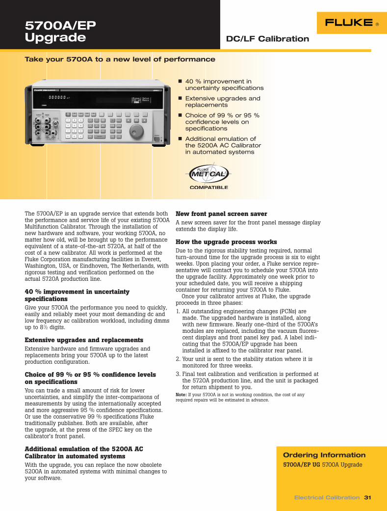
The 5700A/EP is an upgrade service that extends boththe performance and service life of your existing 5700AMultifunction Calibrator. Through the installation ofnew hardware and software, your working 5700A, nomatter how old, will be brought up to the performanceequivalent of a state-of-the-art 5720A, at half of thecost of a new calibrator. All work is performed at theFluke Corporation manufacturing facilities in Everett,Washington, USA, or Eindhoven, The Netherlands, withrigorous testing and verification performed on theactual 5720A production line.
40 % improvement in uncertainty specifications Give your 5700A the performance you need to quickly,easily and reliably meet your most demanding dc andlow frequency ac calibration workload, including dmmsup to 81⁄2 digits.
Extensive upgrades and replacements Extensive hardware and firmware upgrades andreplacements bring your 5700A up to the latestproduction configuration.
Choice of 99 % or 95 % confidence levels on specifications You can trade a small amount of risk for lower uncertainties, and simplify the inter-comparisons of measurements by using the internationally acceptedand more aggressive 95 % confidence specifications.Or use the conservative 99 % specifications Fluketraditionally publishes. Both are available, after the upgrade, at the press of the SPEC key on the calibrator’s front panel.
Additional emulation of the 5200A AC Calibrator in automated systems With the upgrade, you can replace the now obsolete5200A in automated systems with minimal changes toyour software.
5700A/EP Upgrade
n 40 % improvement inuncertainty specifications
n Extensive upgrades andreplacements
n Choice of 99 % or 95 %confidence levels onspecifications
n Additional emulation ofthe 5200A AC Calibratorin automated systems
New front panel screen saver A new screen saver for the front panel message displayextends the display life.
How the upgrade process works Due to the rigorous stability testing required, normalturn-around time for the upgrade process is six to eightweeks. Upon placing your order, a Fluke service repre-sentative will contact you to schedule your 5700A intothe upgrade facility. Approximately one week prior toyour scheduled date, you will receive a shippingcontainer for returning your 5700A to Fluke.
Once your calibrator arrives at Fluke, the upgradeproceeds in three phases: 1. All outstanding engineering changes (PCNs) are
made. The upgraded hardware is installed, alongwith new firmware. Nearly one-third of the 5700A’smodules are replaced, including the vacuum fluores-cent displays and front panel key pad. A label indi-cating that the 5700A/EP upgrade has beeninstalled is affixed to the calibrator rear panel.
2. Your unit is sent to the stability station where it ismonitored for three weeks.
3. Final test calibration and verification is performed atthe 5720A production line, and the unit is packagedfor return shipment to you.
Note: If your 5700A is not in working condition, the cost of anyrequired repairs will be estimated in advance.
Take your 5700A to a new level of performance
DC_LF Cal.qxd 11/12/04 1:11 PM Page 31
riešenia na presné meranie www.elso.sk/Fluke-Calibration
Elso Philips Service, Trenčín
57LFCATE System Source DC/LF Calibration
Tech Tip
32 Electrical Calibration
n High burden and compli-ance output maintainsspecification to overcomeloading from systemconnections and cables
n Emulates Fluke 5700 GPIBcommands
n All external interfaceconnectors convenientlylocated on the front panelfor easy setup and cableconnections
n Lightweight yet ruggeddesign for easy systemdeployment and transportation
n Meets stringent storageand operating MIL specifications
A rugged, accurate source of traceable signals designedfor ATE systems
The Fluke 57LFC is a precision system source designedspecifically for the ATE systems environment. The57LFC sources dc and ac voltage, dc and ac current,and resistance. This rugged, economical signal sourcehas the highly accurate and traceable signals requiredin test systems for electronic products with lowfrequency analog signals.
The Fluke 57LFC is a valuable aid to system built-intest (BIT) diagnostics and routine maintenance. Use itas a stimulus or embedded traceable source to runroutine diagnostics throughout your built-in test environment (BITE) strategy. The 57LFC, used as anembedded system source, will increase system up timeand reduce the need for excess inventory, whileimproving system accuracy and confidence at the test
interface. System traceability, confidence and qualityare transferred to equipment housed within the ATEsystem automatically, through use of user-developeddiagnostic software routines. The 57LFC does not influ-ence system downtime when removed for its periodiccalibration.
The 57LFC is designed to meet the stringentdemands of an ATE environment. Temperature sensors monitor and protect the 57LFC from adverseenvironmental conditions. All signal inputs and outputsare fully protected from reverse voltage and shortcircuiting and can be fully isolated from the systemanalog bus. The 57LFC features a rugged design,weighs less than 40 pounds, and fits into a standardsystem rack environment.
DC Current SpecificationsAbsolute Uncertainty, tcal + 5 °C Maximum Maximum
Ranges + (% of output + A) 1 Year Resolution Compliance Voltage Inductive Load
0 to 220 µA 0.05 % 0.02 µA 1 nA 10 V 300 µH0 to 2.2 mA 0.05 % 0.05 µA 0.01 µA 10 V 300 µH0 to 22 mA 0.05 % 0.25 µA 0.1 µA 10 V 300 µH0 to 220 mA 0.05 % 2.5 µA 1 µA 10 V 300 µH0 to 2.2 A 0.07 % 40 µA 10 µA 4 V 300 µH
DC Voltage SpecificationsAbsolute Uncertainty, tcal + 5 °C
Ranges + (% output + V) 1 Year Resolution Maximum Burden [1]
0 to 220 mV 0.004 % 3 µV 0.1 µV 50 Ω output impedance0 to 2.2 V 0.0025 % 3 µV 1 µV 50 mA0 to 11 V 0.0025 % 30 µV 10 µV 50 mA0 to 22 V 0.0025 % 30 µV 10 µV 50 mA0 to 220 V 0.004 % 300 µV 100 µV 20 mA
[1] Remote sensing provided on all but 220 mV range.Note: minimum output 0 V for all ranges.
Long cable lengthscommonly associatedwith ATE systemsrequire a precisionsource with highburden currents tomaintain accuracyspecifications at thetest head.
DC_LF Cal.qxd 11/12/04 1:11 PM Page 32
riešenia na presné meranie www.elso.sk/Fluke-Calibration
Elso Philips Service, Trenčín
Electrical Calibration 33
Resistance SpecificationsAbsolute Uncertainty
Nominal of Characterized Value, Full MaximumResistance tcal + 5 °C Specification PeakValue [1] + (% of output) 1 Year Current [2] Current
0 Ω 0.001 Ω 8 to 200 mA 220 mA1 Ω 0.001 Ω 8 to 100 mA 220 mA1.9 Ω 0.002 Ω 8 to 100 mA 220 mA10 Ω 0.004 Ω 8 to 11 mA 220 mA19 Ω 0.008 Ω 8 to 11 mA 160 mA100 Ω 0.01 Ω 8 to 11 mA 70 mA190 Ω 0.02 Ω 8 to 11 mA 50 mA1 kΩ 0.1 Ω 1 to 2 mA 22 mA1.9 kΩ 0.2 Ω 1 to 1.5 mA 16 mA10 kΩ 1 Ω 0.1 to 0.5 mA 3 mA19 kΩ 2 Ω 0.05 to 0.25 mA 1.6 mA100 kΩ 10 Ω 0.01 to 0.1 mA 0.3 mA190 kΩ 20 Ω 5 to 50 µA 0.16 mA1 MΩ 100 Ω 5 to 20 µA 30 µA1.9 MΩ 200 Ω 2.5 to 10 µA 16 µA10 MΩ 4 kΩ 0.5 to 2 µA 3 µA19 MΩ 10 kΩ 0.25 to 1 µA 1.6 µA
[1] Discrete resistors with characterized values stored in non-volatile memory. Specifications apply to the characterizedvalue using 4-wire connections.
[2] Active two-wire compensation may be selected for values up to 190 kΩ. Active compensation is 11 mA load and 2 V burden minimum.
AC Voltage SpecificationsAbsolute Uncertainty, tcal + 5 °C
Ranges Frequency + (% output + V) 1 year Resolution Maximum Burden [1][2]
10 mV to 22 mV 10 to 45 Hz 0.15 % 20 µV 1 µV 50 Ω output impedance45 Hz to 20 kHz 0.08 % 20 µV
20 to 50 kHz 0.25 % 20 µV50 to 100 kHz 0.5 % 50 µV
22 mV to 220 mV 10 to 45 Hz 0.15 % 50 µV 1 µV 50 Ω output impedance45 Hz to 20 kHz 0.05 % 50 µV
20 to 50 kHz 0.25 % 50 µV50 to 100 kHz 0.4 % 200 µV
0.22 V to 2.2 V 10 to 45 Hz 0.1 % 250 µV 10 µV 50 mA45 Hz to 20 kHz 0.05 % 100 µV
20 to 50 kHz 0.1 % 320 µV50 to 100 kHz 0.25 % 2000 µV
2.2 V to 22 V 10 to 45 Hz 0.1 % 1 mV 100 µV 50 mA45 Hz to 20 kHz 0.05 % 1 mV
20 to 50 kHz 0.1 % 1 mV50 to 100 kHz 0.25 % 2 mV
22 V to 220 V [2] 10 Hz to 45 Hz 0.1 % 10 mV 1 mV 20 mA45 Hz to 20 kHz 0.05 % 10 mV
20 to 50 kHz 0.25 % 20 mV50 to 100 kHz 0.5 % 50 mV
[1] Remote sensing provided on all but 22 mV and 220 mV ranges. Maximum output current is reduced by 50 % above 40 °C. Maximum load capacitance is 500 pF.
[2] V x Hz limited to 11.8e6.Note: frequency uncertainty is specified to be 0.01 % of frequency setting.
DC_LF Cal.qxd 11/12/04 1:11 PM Page 33
riešenia na presné meranie www.elso.sk/Fluke-Calibration
Elso Philips Service, Trenčín
57LFCATE System Source DC/LF Calibration
34 Electrical Calibration
AC Voltage DistortionMax distortion and noise 10 Hz to
Ranges Frequency 10 MHz Bandwidth ± (% output + V)
10 mV to 22 mV 10 to 45 Hz 0.15 % 90 µV45 Hz to 20 kHz 0.035 % 90 µV20 kHz to 50 kHz 0.15 % 90 µV50 kHz to 100 kHz 0.25 % 90 µV
22 mV to 220 mV 10 to 45 Hz 0.15 % 90 µV45 Hz to 20 kHz 0.035 % 90 µV20 kHz to 50 kHz 0.15 % 90 µV50 kHz to 100 kHz 0.20 % 90 µV
0.22 V to 2.2 V 10 to 45 Hz 0.15 % 200 µV45 Hz to 20 kHz 0.035 % 200 µV20 kHz to 50 kHz 0.15 % 200 µV50 kHz to 100 kHz 0.20 % 200 µV
2.2 V to 22 V 10 to 45 Hz 0.15 % 2 mV45 Hz to 20 kHz 0.035 % 2 mV20 kHz to 50 kHz 0.2 % 2 mV50 kHz to 100 kHz 0.5 % 2 mV
22 V to 220 V 10 Hz to 45 Hz 0.15 % 10 mV45 Hz to 20 kHz 0.05 % 10 mV20 kHz to 50 kHz 0.8 % 10 mV50 kHz to 100 kHz 1.0 % 10 mV
AC Current SpecificationsAbsolute Uncertainty, Maximum Maximum
tcal + 5 °C Compliance Inductive Ranges [2] Frequency + (% of output + A) 1 year Resolution Voltage (rms) Load [1]
30 µA 10 to 20 Hz 0.3 % 0.2 µA 0.01 µA 7 V 50 µHto 20 to 45 Hz 0.15 % 0.2 µA
220 µA 45 Hz to 1 kHz 0.125 % 0.2 µA1 to 5 kHz 0.4 % 0.3 µA5 to 10 kHz 1.5 % 0.4 µA
0.22 mA 10 to 20 Hz 0.2 % 0.3 µA 0.1 µA 7 V 50 µHto 20 to 45 Hz 0.15 % 0.3 µA
2.2 mA 45 Hz to 1 kHz 0.1 % 0.3 µA1 to 5 kHz 0.2 % 0.3 µA5 to 10 kHz 0.8 % 0.5 µA
2.2 mA 10 to 20 Hz 0.2 % 3 µA 1 µA 7 V 50 µH to 20 to 45 Hz 0.1 % 3 µA
22 mA 45 Hz to 1 kHz 0.1 % 3 µA1 to 5 kHz 0.2 % 3 µA5 to 10 kHz 0.4 % 5 µA10 to 20 kHz 0.8 % 5 µA
22 mA 10 to 20 Hz 0.18 % 30 µA 10 µA 7 V 50 µHto 20 to 45 Hz 0.1 % 30 µA
220 mA 45 Hz to 1 kHz 0.1 % 30 µA1 to 5 kHz 0.3 % 50 µA5 to 10 kHz 0.4 % 100 µA10 to 20 kHz 0.8 % 200 µA
0.22 A 10 to 45 Hz 0.18 % 300 µA 100 µA 4 V 2.5 µHto 45 Hz to 1 kHz 0.1 % 300 µA
2.2 A 1 to 5 kHz 1 % 3000 µA5 to 10 kHz 5 % 5000 µA
[1] 400 µH with inductive compensation ON.[2] I-guard, (as on the 5700A rear panel), required when sourcing low-level currents through a long cable.Note: Frequency uncertainty is specified to be 0.01 % of frequency setting.
DC_LF Cal.qxd 11/12/04 1:11 PM Page 34
riešenia na presné meranie www.elso.sk/Fluke-Calibration
Elso Philips Service, Trenčín
Electrical Calibration 35
General Specifications
Warm-up timeTwice the time since last warmedup, to a maximum of 30 minutes
Temperature performanceOperating: 0 to 50 °CCalibration (tcal): 15 to 37.7 °CStorage: –40 to 75 °C
Temperature coefficientTemperature coefficient for temper-atures outside tcal +5 °C is 10 % ofthe 1-year spec per °C
Relative humidityOperating: < 80 % to 30 °C, < 70 %to 40 °C, < 40 % to 50 °CProvide typical specification for 43°C at 95 % non-condensingStorage: < 95 %, non-condensing
AltitudeOperating: 3,050 m (10,000 ft)maximumNon-operating: 12,200 m (40,000 ft) max.
SafetyDesigned to comply with IEC 61010-1 2000-1; ANSI/ISA-S82.01-1994; CAN/CSA-C22.2 No. 1010.1-92
Analog low isolation20 V
Ordering InformationModels57LFC ATE System SourceOptions and AccessoriesY5537A Comprehensive RackMount Kit
EMCDesigned to comply with IEC61326-1 2000-11 (EMC)
Line powerLine voltage (selectable): 100 V, 120 V, 208 V, and 230 VLine frequency: 47 to 63 HzLine voltage variation: ± 7 % aboutline voltage settingMaximum VA: 200
Settling time≤ 3 to 10 seconds, similar to 5700A
Dimensions7" x 17" x 18" maximum chassis H x W x D
WeightLess than 40 pounds (less than 18 kg)
Electrical/signal interfaceFluke 5700A/LP* equivalent signalinterface, AC Mains, IEEE-488, andRS232 connectors, AC powerswitch, and Line Voltage selectionon front panel
Cooling50 cubic feet per minute*Fluke 5700A/LP special build configurationfor Navy CASS program
DC_LF Cal.qxd 11/12/04 1:11 PM Page 35
riešenia na presné meranie www.elso.sk/Fluke-Calibration
Elso Philips Service, Trenčín
DC/LF Calibration
36 Electrical Calibration
525A Temperature/Pressure Calibrator
Tech Tip
n Calibrates a wide varietyof thermocouple instrumentation
n Highly accurate simula-tion and measurement of RTD probes
n Direct measurement ofall Fluke 700 Series and525A-P pressuremodules
n Converts easily to anypressure unit
n Sources dc voltage to100 V and current to 100 mA at 30 ppm
Superior accuracy and functionality in an economicalbenchtop package
The Fluke 525A Temperature/Pressure Calibrator givesyou a workhorse combination of high accuracy andbroad functionality for temperature and pressureinstrument calibration. Compact and economical, the525A has an interface for automated calibration,providing wide workload coverage in instrument shopsand calibration labs, as well as in ATE applications.The 525A is the most accurate Fluke temperature cali-brator, sourcing and measuring a complete range of
RTDs, thermocouples, and thermistors. It also measurespressure covering common ranges from 1 inch (6900 Pa)of water up to 10,000 PSI (69 MPa) using the Fluke700 Series (0.05 %) pressure modules and the 525A-P(0.02 %) Series Pressure Modules. Plus, the dc voltageand current specifications of the 525A enable you tocalibrate other process calibrators and a wide varietyof other instruments with accuracy that rivals any cali-brator in its price range.
DC Voltage Specifications, OutputAbsolute Uncertainty, tcal ± 5 °C
± (ppm of output + µV) Stability
24 hours, ± 1 °C MaximumRanges [1] 90 days 1 year ± (ppm of output + µV) Resolution Burden [2]
0 to 100.000 mV 25 3 µV 30 3 µV 5 + 2 1 µV 10 mA0 to 1.00000 V 25 20 µV 30 20 µV 4 + 20 10 µV 10 mA0 to 10.0000 V 25 200 µV 30 200 µV 4 + 200 100 µV 10 mA0 to 100.000 V 25 2 mV 30 2 mV 5 + 1 mV 1 mV 1 mA
[1] All outputs are positive only.[2] Remote sensing is not provided. Output resistance is < 1 Ω.
The 525A makes anexcellent pressurereadout standard usingthe 525A-P PressureModules.
DC Current Specifications, OutputAbsolute Uncertainty, tcal ± 5 °C Maximum Maximum
± (ppm of output + µA) Compliance InductiveRanges [1] 90 days 1 year Resolution Voltage Load
0 to 100.000 mA 85 2 100 2 1 µA 10 V 100 µH
[1] All outputs are positive only.
DC_LF Cal.qxd 11/12/04 1:11 PM Page 36
riešenia na presné meranie www.elso.sk/Fluke-Calibration
Elso Philips Service, Trenčín
Electrical Calibration 37
Resistance Specifications, OutputAbsolute Uncertainty, tcal ± 5 °C
± (ppm of output + Ω) AllowableRanges [1] 90 days 1 year Resolution Current [2]
5 to 400.00 Ω 0.025 0.03 0.01 Ω 1 to 10 mA5 to 4.0000 kΩ 0.25 0.3 0.1 Ω 250 µA to 1 mA
[1] Continuously variable from 0 to 4 kΩ.[2] For currents lower than shown, the floor adder increases by Floor(new) = Floor(old) x Imin/Iactual. For example, a 500 µA
stimulus measuring 100 Ω has a floor uncertainty of 0.025 Ω x 1 mA/500 µA = 0.05 Ω.
Resistance Specifications, InputAbsolute Uncertainty, tcal ± 5 °C
± (ppm of output + Ω) StimulusRanges 90 days 1 year Resolution Current
0 to 400.00 Ω 35 0.003 40 0.003 0.001 Ω 1 mA401 to 4001.00 Ω 35 0.03 40 0.03 0.01 Ω 0.1 mA
Thermocouple Specification, Output and InputAbsolute Uncertainty,tcal ± 5 °C, ± (°C) [1]
Range (°C) Output/Input
TC Type [2] Minimum Maximum 90 days 1 year
B 600 °C 1820 °C 0.42 °C 0.46 °CC 0 °C 2316 °C 0.25 °C 0.84 °C
E –250 °C –100 °C 0.38 °C 0.50 °C–100 °C 1000 °C 0.16 °C 0.21 °C
J –210 °C –100 °C 0.20 °C 0.27 °C–100 °C 1200 °C 0.18 °C 0.23 °C
K –200 °C –100 °C 0.25 °C 0.33 °C–100 °C 1372 °C 0.19 °C 0.40 °C
L –200 °C 900 °C 0.37 °C 0.17 °CN –200 °C 1300 °C 0.33 °C 0.27 °CR 0 °C 1750 °C 0.58 °C 0.40 °CS 0 °C 1750 °C 0.56 °C 0.46 °C
T –250 °C –150 °C 0.51 °C 0.63 °C –150 °C 400 °C 0.18 °C 0.14 °C
U –200 °C 0 °C 0.56 °C 0.56 °C0 °C 600 °C 0.27 °C 0.27 °C
mV –10 to 75.000 mV[1] Does not include thermocouple wire error.[2] Also excludes type XP and BP.
TC mV Specifications, Input and OutputAbsolute Uncertainty, tcal ± 5 °C
± (ppm of output + µV) Stability
24 hours, ± 1 °C MaximumRange (mV) 90 days 1 year ± (ppm of output + µV) Resolution Burden
RTD and Thermistor Specification, OutputAbsolute Uncertainty, tcal ± 5 °C
Range (°C) ± (°C) [1]
RTD Type Minimum Maximum 90 days 1 year
Pt 385, 100 Ω –200 °C 800 °C 0.06 °C 0.10 °CPt 3926, 100 Ω –200 °C 630 °C 0.06 °C 0.09 °CPt 3916, 100 Ω –200 °C 630 °C 0.06 °C 0.09 °CPt 385, 200 Ω –200 °C 630 °C 0.31 °C 0.50 °CPt 385, 500 Ω –200 °C 630 °C 0.13 °C 0.19 °CPt 385, 1000 Ω –200 °C 630 °C 0.06 °C 0.09 °CPtNi 385, 120 Ω –80 °C 260 °C 0.04 °C 0.03 °C(Ni 120)Cu 427, 10 Ω [2] –100 °C 260 °C 0.63 °C 0.75 °CYSI 400 15 °C 50 °C 0.005 °C 0.007 °C
[1] 2-wire output[2] Based on MINCO Application Aid No. 18.
RTD and Thermistor Specification, InputAbsolute Uncertainty, tcal ± 5 °C
Range (°C) ± (°C) [1]
RTD Type Minimum Maximum 90 days 1 year
Pt 385, 100 Ω –200 °C 80 °C 0.031 °C 0.012 °C0 °C 100 °C 0.018 °C 0.020 °C
100 °C 630 °C 0.027 °C 0.047 °C630 °C 800 °C 0.050 °C 0.057 °C
Pt 3926, 100 Ω –200 °C 100 °C 0.031 °C 0.019 °C0 °C 630 °C 0.018 °C 0.046 °C
100 °C 0.026 °CPt 3916, 100 Ω –200 °C 630 °C 0.026 °C 0.047 °CPt 385, 200 Ω –200 °C 630 °C 0.071 °C 0.106 °CPt 385, 500 Ω –200 °C 630 °C 0.046 °C 0.076 °CPt 385, 1000 Ω –200 °C 100 °C 0.031 °C 0.040 °C
0 °C 630 °C 0.039 °C 0.047 °CPtNi 385, 120 Ω –80 °C 260 °C 0.209 °C 0.212 °C(Ni120)Cu 427, 10 Ω [2] –100 °C 260 °C 0.300 °C 0.069 °CYSI 400 15 °C 50 °C 0.005 °C 0.304 °CSPRT, 25 Ω User Defined User Defined 0.05 °C 0.06 °C
[1] 4-wire mode. Uncertainties listed do not include probe uncertainties.[2] Based on MINCO Application Aid No. 18.
General Specifications
Warm up time: Twice the time sincelast warmed up, to a maximum of30 minutesSettling time: Less than 5 secondsfor all functions and ranges exceptas notedStandard interface: RS-232Optional interface: IEEE-488 (GPIB)
Temperature performanceOperating: 0 °C to 50 °CCalibration (tcal): 18 °C to 28 °CStorage: –20 °C to 70 °CElectromagnetic compatibility: CE,conforms to EN61326Temperature coefficient: For temper-atures outside tcal ± 5 °C is 10 % ofthe 90 day specification (or 1 yearif applicable) per °C
Relative humidityOperating: < 80 % to 30 °C, < 70 %to 40 °C, < 40 % to 50 °CStorage: < 95 % noncondensing
AltitudeOperating: 3,050 m (10,000 ft)maximumNonoperating: 12,200 m (40,000 ft)maximum
Line powerLine Voltage (selectable): 100 V/120 V or 220 V/240 VLine Frequency: 47 to 63 HzLine Voltage Variation: ± 10 %about line voltage settingPower consumption: 15 VA maximum
DimensionsHeight: 13.3 cm (5.25 in) plus 1.5 cm (0.6 in) four feet on bottomWidth: 3/4 standard rack widthDepth: 47.3 cm (18.6 in) overallWeight (without options): 4 kg (9 lb)
CalibrationNIST traceable with data
DC_LF Cal.qxd 11/12/04 1:11 PM Page 38
riešenia na presné meranie www.elso.sk/Fluke-Calibration
Fluke offers a variety of oscillo-scope calibration solutions tomatch just about every workloadand budget. For dedicated oscil-loscope calibration workloads,the 9500B offers the highestperformance, fully automatedcalibration with leveled sinewaves to 6.4 GHz and edges to25 ps. The 5820 calibrates oscilloscopes in the bandwidthrange up to 2.1 GHz for upgrade-able entry level performance.
If oscilloscopes are only part ofyour workload, your best solutionmight be in the scope cal optionsavailable for the 5520A or 5500AMulti-Product Calibrators, or the9100 Universal CalibrationSystem. These products calibratea wide workload in addition tooscilloscopes.
riešenia na presné meranie www.elso.sk/Fluke-Calibration
Elso Philips Service, Trenčín
9500B Oscilloscope Calibrator
Tech Tip
Electrical Calibration 41
OscillscopeCalibration
9500 Active Heads canbe calibrated awayfrom the mainframe, soyou can schedule cali-brations of individualheads at differenttimes. That way, youcan keep the 9500system available foruse for a greaterpercentage of time.
n Full automation providestotally hands-free oscilloscope calibration
n Continuous upgradeabilityhelps you protect yourinvestment
n Up to five channels simultaneous output
n Leveled sine waves to 6.4 GHz and edges to 25 ps
n Fluke’s unique Active HeadTechnology generates cali-bration signals right at theoscilloscope input
n Software and procedures
The highest performance, fully automated, upgradeableoscilloscope calibration workstation
The Fluke 9500B Oscilloscope Calibration Workstationbrings the benefits of hands-free, fully-automated,accurate oscilloscope calibration to everyone at a priceand performance level that your needs and budget cansupport, while ensuring that, through performanceupgrades, future needs will be met when the timedemands it.
Active Heads provide full automation The Fluke 9500B provides true, full automation throughthe use of its unique Active Heads. With the 9500B, allthe signals required to fully calibrate the oscilloscopeare generated in detachable heads, remote from thecalibrator mainframe. The heads are connected directlyto the oscilloscope input without the need for addi-tional cables. All control and switching of waveformsare performed under the control of the mainframe, yetwithin the head itself — typically only a matter ofmillimeters away from the oscilloscope input andamplifiers. With each 9500B mainframe able to controlup to five heads, all the signals required to calibrate afour-channel oscilloscope with an external trigger canbe supplied, controlled and switched without operatorintervention or the need for external switching.
9560 Active Head — for ultimate leveled sineperformance to 6.4 GHz The latest member of the Active Head family, 9560,allows existing users of the 9500 to upgrade theirequipment to any 9500B status and take advantage ofmore recent product and performance enhancements.The 9560 is able to deliver 6.4 GHz leveled sine waveand pulse edges of 70 ps.
Unlike other oscilloscope calibrators, you’re notrestricted to fixed amplitude pulses. Active Head Tech-nology™ lets you adjust output amplitude between 4.44 mV and 3.1 V, allowing you to check an oscillo-scope’s amplifiers right down to their most sensitiveranges. Whatever amplitude you choose, controlledwave shape filtering ensures that all high-speed edgeshave an accurately defined energy distribution.
Fully compatible with MET/CAL® PlusCalibration Management Software The final link in the chain of full automation is soft-ware. The 9500B Oscilloscope Calibrator can be usedwith the powerful IEEE-488 (GPIB) based MET/CAL®
Plus auto-mated calibration management software.
Oscilloscope Cal.qxd 11/12/04 1:36 PM Page 41
riešenia na presné meranie www.elso.sk/Fluke-Calibration
While allowing you to automate the calibrationprocess, MET/CAL also documents results, managesyour calibration inventory, and allows you to developnew oscilloscope calibration procedures. Runningunder Microsoft Windows® and supporting multi-usernetworking, the software implements advancedfeatures such as ISO 9000 compliant traceability,custom certificate and report generation, and high-level procedure programming. The result is higherworkload throughput, better calibration consistency,minimization of human error, and fewer requirementsfor operator training — in short, higher quality calibra-tion at lower cost.
Gold procedure support Fluke’s MET/SUPPORT Gold Software Support Program,available by annual subscription, gives you free accessto all procedures written by the Fluke software supportteam, plus a host of additional benefits, including freesoftware upgrades and discounts on custom proceduredevelopment. Even if you only use a few of the GoldServices in a year, you can easily recover more thanthe cost of your membership fee.
Note: For full and comprehensive specifications, refer to the Extended Specifications data sheet, available at www.fluke.comAll Specifications TCal ± 5 °C, 1 year, 99 % where Factory TCal = 23 °C (except frequency accuracies 5 years). Uncertainties are fully inclusive of instrument errors, resolution, stability, regulation and traceability to National Standards. In general, nothing further needs to be added to determine testuncertainty ratio against the equipment under calibration.
Voltage Function (not available via 9550 Active Head)
DC DC Square Wave Square WaveInto 1 MΩ Into 50 Ω Into 1 MΩ Into 50 Ω
Amplitude ± 1 mV to ± 200 V ± 1 mV to ± 5 V 40 µV to 200 V pk-pk 40 µV to 5 V pk-pk
Ranging Volt/div factors of 1, 2, 5 or 1, 2, 2.5, 4, 5; or continuously variableDeviation ± 11.2 % (Including over and underrange)Rise/fall time < 100 V pkpk < 150 ns; ≥ 100 V pkpk < 200 nsAberrations < 2 % peak for first 500 nsFrequency 10 Hz to 100 kHz
DC into 1 MΩ available at all heads without specification degradation.
Edge Function (9550 Active Head supports 25 ps Fast Edge only)
150 ps Fast-Edge 70 ps Fast-Edge 25 ps Fast-Edge500 ps Edge Pulse HV Edge Pulse (9530 Head Only) (9560 Head Only) (9550 Head Only)Into 50 Ω or 1 MΩ Into 1 MΩ Into 50 Ω Into 50 Ω Into 50 Ω
425 mV toAmplitude 5 mV to 3 V pk-pk 1 mV to 200 V pk-pk [1] 5 mV to 3 V pk-pk 25 mV to 2 V pk-pk 575 mV pk-pk
Polarity Rising and falling Rising and falling Rising and falling Rising Rising and fallingReturn to ground Return to ground Return to ground Rising and falling Return to ground
Rise/fall time < 100 V pk-pk < 150 ns [2]
(10 % to 90 %) 500 ps ≥ 100 V pk-pk < 200 n [2] 150 ps 70 ps 25 ps
Frequency 10 Hz to 2 MHz 10 Hz to 100 kHz 10 Hz to 2 MHz 10 Hz to 1 MHz 10 Hz to 1 MHzTrigger toedge delay 25 ns (typical)
Trigger to 5 ps pk-pkedge jitter
[1] 1 mV to 5 V pk-pk into 50 Ω.[2] Into 50 Ω < 100 ns.Edge speeds faster than 500 ps are not recommended for 1 MΩ input applications. 9560 and 9550 50 Ω only.
Oscilloscope Cal.qxd 11/12/04 1:36 PM Page 42
riešenia na presné meranie www.elso.sk/Fluke-Calibration
Timing Marker Function (not available via 9550 Active Head)
Styles Square Sine Pulse Narrow Triangle
Period 9.0091 ns to 55 s 450.5 ps to 9.009 ns 900.91 ns to 55 s 900.91 ns to 55 s9500/600 (909.1 ns min)
9560 (180.19 ps min)Ranging Time/div ranging 1, 2, 5 or 1, 2, 2.5, 4, 5 or continuously variableDeviation ± 45 % (including overrange)Rise/fall times 1 ns typical N/A 1 ns typical 2.5 % of periodTiming accuracy < 83 µs ± 0.25 ppm, ≥ 83 µs ± 3 ppmAmplitude 100 mV to 1 V pk-pkSub-division Every tenth marker can be set to higher amplitude for periods ≥ 1 µs for all waveshapes
Line frequency timing markers are available in square waveform. Jitter wrt line zero crossing ± 20 µs pk-pk.Periods below 2 ns are not recommended for 1 MΩ input applications. 9560 50 Ω only.
Leveled Sine Function (not available via 9550 Active Head)
9500B/600 9500B/1100 9500B/3200 and 9530 9500B/3200 and 9560
Frequency range 0.1 Hz to 600 MHz 0.1 Hz to 1.1 GHz 0.1 Hz to 3.2 GHz 0.1 Hz to 6.4 GHzAmplitude (pk-pk) 0.1 Hz to 550 MHz 0.1 Hz to 550 MHz 0.1 Hz to 550 MHz 0.1 Hz to 550 MHz(into 50 Ω) 5 mV to 5 V 5 mV to 5 V 5 mV to 5 V 5 mV to 5 V
550 MHz to 600 MHz 550 MHz to 1.1 GHz 550 MHz to 2.5 GHz 550 MHz to 2.5 GHz5 mV to 3 V 5 mV to 3 V 5 mV to 3 V 5 mV to 3 V
2.5 GHz to 3.2 GHz 2.5 GHz to 3.2 GHz5 mV to 2 V 5 mV to 2 V
3.2 GHz to 6.4 GHz25 mV to 2 V
Accuracy ± 1.5 % at single ref frequency (50 kHz to 10 MHz)Flatness wrt 0.1 Hz to 300 MHz 0.1 Hz to 300 MHz 0.1 Hz to 300 MHz 0.1 Hz to 300 MHzref frequency ± 2.0 % ± 2.0 % ± 2.0 % ± 2.0 %Into VSWR 300 MHz to 550 MHz 300 MHz to 550 MHz 300 MHz to 550 MHz 300 MHz to 550 MHzof 1.6:1 (1.2:1) ± 3 % (± 2.5 %) ± 3 % (± 2.5 %) ± 3 % (± 2.5 %) ± 2.5 % (± 2.5 %)
Pulse Width Function (not available via 9550 Active Head)
Pulse width 1 n to 100 nsAccuracy < ± 5 % ± 200 psAdjustment resolution 1 ns to 4 ns, < 50 ps
4 ns to 20 ns < 250 ps20 ns to 100 ns <1 ns
Rise and fall time < 450 psAberrations < ± 5 % pk (typical)Width stability < 10 ps pk-pk 10 mins/1 ºCPulse jitter (wrt trigger) < 5 ps pk-pkFrequency 1 kHz to 1 MHzAmplitude 1 V pk-pk into 50 Ω
Other Output Functions (not available via 9550 Active Head)
Current DC Square Wave
Amplitude ± 100 µA to ± 100 mA ± 100 µA to ± 100 mA pk-pkAccuracy ± (0.25 % + 0.5 µA)Duty cycle and symmetry 50 %, symmetrical about groundRise time and aberrations < 150 ns and < 2 % pkRequires 9530 or 9510 Head and BNC current adapter
Composite Video Output
Amplitude 1.0 V pk-pkPattern (full raster) White, grey or blackSync polarity Positive or negativeStandards 625-line 50 Hz, 525-line 60 HzTrigger output Composite sync or odd field start9560 50 Ω only
Auxiliary Input
Signal routing Rear SMA input, passive and switched 50 Ω path to any Active HeadMaximum input ± 40 V pk-pk, ± 400 mA pk-pkInsertion loss (into 50 Ω) to 100 MHz < 2.5 dB, to 500 MHz < 4 dB, to 1 GHz < 6 dB
Reference Frequency Input (BNC) Output (BNC)
Frequency range 1 MHz to 20 MHz in 1 MHz steps 1 MHz or 10 MHzLevel (typical) 90 mV to 1 V pk-pk Into 50 Ω 1 V pk-pk,
Into 1 M Ω 2 V pk-pkLock range ± 50 ppm
Other Output FunctionsOverload Pulse
Amplitude 5 V to 20 V into 50 ΩPolarity Positive/NegativeDuration 0.2 s to 100 s (subject to pulse energy limits)Energy power in 50 Ω 1.6 J to 50 J, 0.5 Ω to 8 ΩTrigger Manual max. rep rate 0.3 Hz (internally limited)Zero Skew
Unadjusted skew < ± 25 ps ch to chAdjusted skew < ± 5 ps ch to chSkew temp coef < 0.2 ps/°CRise and fall time 450 ps typicalRelative jitter < 7 ps pk-pkInput Leakage Function
Open circuit output Leakage < ± 50 pAShort circuit output Offset < ± 15 µVLF Linear Ramp
Waveforms 1 V pk-pk triangle symmetrical about groundLinearity < ± 0.1 % deviation over 10 to 90 %Ramp time 1 ms, 10 ms, 100 ms or 1 s
Oscilloscope Cal.qxd 11/12/04 1:36 PM Page 44
riešenia na presné meranie www.elso.sk/Fluke-Calibration
Elso Philips Service, Trenčín
Electrical Calibration 45
General Specifications
EnvironmentalTemperatureOperating: 5 °C to 40 °CStorage: 0 °C to 50 °C, transit < 100 hours –20 °C to 60 °CHumidity (non-condensing)Operating: < 90 % 5 °C to 30 °C< 75 % 30 °C to 40 °CStorage: <95 % 0 °C to 50 °C
SafetyDesigned to and documented toEN61010-1-11993/A21995 CE and ETL marked
EMC (including options)Radiated Emissions: EN55011/22FCC Rules part 15 subpart J class BRadiated Immunity: EN50082-1
Ordering InformationModels9500B/600 600 MHz High-Performance OscilloscopeCalibrator Workstation9500B/1100 1100 MHz High-Performance OscilloscopeCalibrator Workstation9500B/3200 3.2 GHz High-Performance OscilloscopeCalibrator Workstation9560 FLK Active Head with 6.4 GHz and 70 ps pulse capability9510 FLK Active Head with 1.1 GHz and 50 ps pulse capability9530 FLK Active Head with 3.2 GHz and 150 ps/500 ps pulse capability9550 FLK Active Head with 25 ps pulse capabilityOptions and Accessories9500-60 Soft Carrying Case 9500-65 Rugged Transit Case9500-90 Rack Mounting Kit9500 Base ChassisUpgrades95/400-9500/600UG Upgrade9500/400 to 9500/600
Conducted Emissions: EN550111991 Class BConducted Immunity: EN50082-1Harmonics: EN61000-3-2Shock and Vibration: MIL-T-28800type III, Class 5, style E
PowerLine Voltage: 95 V to 132 V rms,209 V to 264 V rms installationCAT IILine Frequency: 48 Hz to 63 HzPower Consumption: < 400 VAWarmup: 20 minutes
Dimensions9500 Base Unit: 133 H x 427 W x440 D mm (5.24 H x 16.8 W x 17.3 D in)95xx Active Heads: 65 H x 31 W x140 D mm (2.56 H x 1.22 W x 5.51 D in)
Weight9500 Base Unit: 12 kg (27 lbs)approx.95xx Active Heads: 0.45 kg (1 lb)approx.
Warranty period9500 Base Unit: One-year95xx Active Heads: Three-yearActive Plus CarePlan
CalibrationStandard: NPL-UK traceable calibration certificate with data. An accredited calibration certificateis available.
95/400-9500/1100UG Upgrade9500/400 to 9500/110095/400-9500/3200UG Upgrade9500/400 to 9500/3200firmware compatible with 9560modules, include upgrade to 5 channels and simultaneous 5-channel output functions95/600-9500/1100UG Upgrade9500/600 to 9500/110095/600-9500/3200UG Upgrade9500/600 to 9500/3200firmware compatible with 9560modules, include upgrade to 5 channels and simultaneous 5 channel output functions95/1100-95/3200UG Upgrade9500/1100 to 9500/3200firmware compatible with 9560modules, include upgrade to 5 channels and simultaneous 5 channel output functions95/3200-95/3200UG Upgrade9500/3200 to 9500/3200firmware compatible with 9560modules, include upgrade to 5 channels and simultaneous 5 channel output functionsFluke 9500B BaseChassis Upgrades95B/600-95B/1100UG Upgrade9500B/600 to 9500B/110095B/600-95B/3200UG Upgrade9500B/600 to 9500B/3200
95B/1100-95B/3200U Upgrade9500B/1100 to 9500B/3200Wavetek-Datron 9500 Upgrades95/400-95B/3200UG Upgrade9500/400 to 9500B/3200,include upgrade to 5 channels,9560 capability, narrow pulseand simultaneous 5 channeloutput functions95/600-95B/3200UG Upgrade9500/600 to 9500B/3200,include upgrade to 5 channels,9560 capability, narrow pulseand simultaneous 5 channeloutput functions95/1100-95B/3200UG Upgrade9500/1100 to 9500B/3200,include upgrade to 5 channels,9560 capability, narrow pulseand simultaneous 5 channeloutput functions95/3200-95B/3200UG Upgrade9500/3200 to 9500B/3200,include upgrade to 5 channels,9560 capability, narrow pulseand simultaneous 5 channeloutput functionsSoftwareMET/CAL® Plus Automated Calibration Management Software
Oscilloscope Cal.qxd 11/12/04 1:36 PM Page 45
riešenia na presné meranie www.elso.sk/Fluke-Calibration
Dedicated oscilloscope calibration that is flexible, powerfuland affordable
Connecting to thescope is easy and reliable with the highquality coaxial cablesof the 5820A. Intendedfor scopes with band-widths up to 2.1 GHz,the calibrating signal’squality remains high,and the calibrationtechnique is simple.
The Fluke 5820A Oscilloscope Calibrator is designed tocalibrate all the ranges and functions of the majority ofdigital and analog oscilloscopes in use or beingpurchased today in the 500 MHz to 2.1 GHz bandwidthrange. The 5820A connects to the unit under test viacharacterized cable interconnections, so it is easy touse and maintain.
The 5820’s five-channel output option facilitatesfast, hands-free automated calibration. Both the 2.1 GHz upgrade option and the five-channel outputoption can be added later, enabling the 5820A to keep up with your labs changing requirements.
Note: For full and comprehensive specifications, refer to the 5820A Oscilloscope CalibratorSpecifications data sheet, available at www.fluke.com.
Voltage FunctionVolt Function DC Signal Square Wave Signal [1]
Load into 50 Ω into 1 MΩ into 50 Ω into 1 MΩ
Amplitude range 0 V to ± 6.6 V 0 V to ± 130 V ± 1 mV to ± 1 mV to± 6.6 V p-p ± 130 V p-p
1-year absolute uncertainty, ± (0.25 % of ± (0.025 % of ± (0.25 % of ± (0.05 % oftcal ± 5 °C output + 40 µV) output + 25 µV) output + 40 µV) output + 5 µV)Sequence 1-2-5 (e.g., 10 mV, 20 mV, 50 mV)Frequency range 10 Hz to 10 kHz1year absolute uncertainty, ± (0.33 ppm of setting)tcal ± 5 °C
[1] Positive or negative, zero referenced square wave.
Edge Function1-Year Absolute Uncertainty,
Edge Characteristics into 50 Ω tcal ± 5 °C
Amplitude range (p-p) 4.0 mV to 2.5 V ± (2 % of output + 200 µV)Frequency range 1 kHz to 10 MHz ± (0.33 ppm of setting)Rise time ≤ 300 ps + 0/–100 psTypical jitter, edge to trigger < 3 ps (p-p) •Leading edge aberrations within 2 ns from 50 % of rising edge < (3 % of output + 2 mV)
2 ns to 5 ns < 2 % of output + 2 mV)5 ns to 15 ns < (1 % of output + 2 mV)after 15 ns < (0.5 % of output + 2 mV)
Oscilloscope Cal.qxd 11/12/04 1:36 PM Page 46
riešenia na presné meranie www.elso.sk/Fluke-Calibration
For specifications on other functions, including wave generator, 1 ns pulse generator, trigger function, tunnel diode drive,current output function, measurement functions and the auxilliary input, please refer to the 5820A Extended Specifications,available at www.fluke.com.
Oscilloscope Cal.qxd 11/12/04 1:36 PM Page 47
riešenia na presné meranie www.elso.sk/Fluke-Calibration
Warmup timeTwice the time since last warmedup, to a maximum of 30 minutes
Settling time5 seconds or faster for all functionsand ranges
Standard interfacesIEE488 (GPIB), RS-232
Temperature performanceOperating: 0 °C to 50 °CCalibration (Tcal): 15 °C to 35 °CStorage: –20 °C to 70 °C
Electromagnetic compatibilityDesigned to operate in StandardLaboratory environments where theElectromagnetic environment ishighly controlled. If used in areaswith Electromagnetic fields > 1 V/m, there could be errors incurrent output values.
Temperature coefficientTemperature Coefficient for temper-atures outside tcal ± 5 °C: add 0.1 x1-year specification/°C
Relative humidityOperating: < 80 % to 30 °C, < 70 % to 40 °C, < 40 % to 50 °CStorage: < 95 %, non-condensing
AltitudeOperating: 3,050 m (10,000 ft)maximumNon-operating: 12,200 m (40,000 ft) maximum
SafetyDesigned to comply with IEC 1010-1 (19921);ANSI/ISAS82.01-1994; CAN/CSA-C22.2 No. 1010, 1-92
Analog low isolation20 V
EMCComplies with EN 61326-1
Ordering InformationModels5820A Oscilloscope CalibratorOptions and Accessories5800A/TDP 125 ps Tunnel DiodePulser for the 5820A5500A/CASE Transit case withwheels5500A/HNDL Side HandleY5537 Rack Mount KitUpgrades5800A-GHz UGK Upgrades existing 5800A to add 2.1 GHzcapability5820A-GHz UGK Upgrades existing 5820A to 2.1 GHz capability5820A-5C UGK Upgrades existing 5820A to 2.1 GHz, five-channelsSoftwareMET/CAL® Plus Automated Calibration Management Software
Line powerLine Voltage (selectable): 100 V,120 V, 220 V, 240 VLine Frequency: 47 to 63 HzLine Voltage Variation: ± 10 %about line voltage setting
Power consumption250 VA
DimensionsHeight: 17.8 cm (7 in), standard rackincrement, plus 1.5 cm (0.6 in) forfeet on bottom of unitWidth: 43.2 cm (17 in), standardrack widthDepth: 47.3 cm (18.6 in) overall
riešenia na presné meranie www.elso.sk/Fluke-Calibration
Elso Philips Service, Trenčín
5500A/5520A OscilloscopeCalibration Options
Tech Tip
Electrical Calibration 49
OscillscopeCalibration
n Oscilloscope calibrationoptions extend the wideworkload coverage of themulti-product calibrators
n More ways to match theright oscilloscope calibrationtools with your workloadand budget
Fully calibrate oscilloscopes to 300 MHz or 600 MHz/300 ps,or to 1.1 GHz
5520A Calibrator
5500A Calibrator
Upgrades to add orimprove the scopeoption to existing calibrators are easyand available. ContactFluke for details.
The SC300 and SC600 options enable the versatile5500A and the enhanced performance 5520A to cali-brate the most widely used analog and digital oscillo-scopes up to 300 MHz and 600 MHz, respectively. TheSC1100 enables the 5520A to calibrate oscilloscopesup to 1.1 GHz with rise times to 300 ps — even 125 pswith the 5800A/TDP tunnel diode pulser option. That
represents what is likely the highest level of oscillo-scopes in your workload — along with the other workload the 5520A addresses.
Each option is a plug-in module that fits inside the5500A or 5520A Multi-Product Calibrator. It can beordered factory installed with a new calibrator, oradded later at a Fluke service center for an additionalinstallation and calibration charge.
Voltage Function Specifications for 5520A-SC1100 and 5500A-SC600Volt Function DC Signal Square Wave Signal [1]
Load Into 50 Ω Into 1 MΩ Into 50 Ω Into 1 MΩ
Amplitude Characteristics
Range 0 V to ± 6.6 V 0 V to ± 130 V ± 1 mV to ± 6.6 V p-p ± 1 mV to ± 130 V p-pResolution
1 mV to 24.999 mV 1 µV25 mV to 109.99 mV 10 µV110 mV to 2.1999 V 100 µV2.2 V to 10.999 V 1 mV11 V to 130 V 10 mVAdjustment range Continuously Adjustable
1-year absolute uncertainty, tcal ± 5 °C ± (0.25 % of output ± (0.05 % of output ± (0.25 % of output ± (0.1 % of output+ 40 µV) + 40 µV) + 40 µV) + 40 µV) [2]
Range 10 Hz to 10 kHz1-year absolute uncertainty, tcal ± 50 °C ± (2.5 ppm of setting)Typical abberation (from 50 % of leading/trailing edge)25 mV to 130 V: within 4 µs < (0.5 % of output + 100 µV)10 mV to 25 mV: within 8 µs1 mV to 10 mV: within 14 µs
[1] Positive or negative, zero referenced square wave. [2] Above 1 kHz, ± (0.25 % of output + 40 µV). Assumes connectors and cables are in good condition.
Oscilloscope Cal.qxd 11/12/04 1:36 PM Page 49
riešenia na presné meranie www.elso.sk/Fluke-Calibration
Note: For full and comprehensive specifications, refer to the 5500A/5520A Multi-Product Calibrators Oscilloscope OptionsExtended Specifications data sheet, available at www.fluke.com.
Voltage Function for 5500A-SC300Volt Function DC Signal Square Wave Signal [1]
Load Into 50 Ω Into 1 MΩ Into 50 Ω Into 1 MΩ
Amplitude range 0 V to ± 2.2 V 0 V to ± 33 V ± 1.8 mV to 1.8 mV to2.2 V p-p ± 105 V p-p
1-year absolute uncertainty, tcal ± 5 °C ± (0.25 % of output + 100 µV)Sequence 1-2-5 (e.g., 10 mV, 20 mV, 50 mV)Frequency range 10 Hz to 10 kHz
[1] Positive or negative, zero referenced square wave.
Edge Function for 5520A-SC1100 and 5500A-SC6001-Year Absolute Uncertainty,
Edge Characteristics into 50 Ω tcal ± 5 °C
Amplitude
Rise time < 300 ps + 0/–100 psRange (p-p) 5.0 mV to 2.5 V ± (2 % of output + 200 µV)Resolution 4 digitsAdjustment range ± 10 % around each sequence
Frequency range 1 kHz to 10 MHz [1] ± (2.5 ppm of setting)Frequency range ≤ 300 ps [1] (+ 0 ps /–100 ps)Typical jitter, edge to trigger < 5 ps (p-p)Leading edge aberrations [2] within 2 ns from 50 % of rising edge < (3 % of output + 2 mV)
2 ns to 5 ns < (2 % of output + 2 mV)5 ns to 15 ns < (1 % of output + 2 mV)after 15 ns < (0.5 % of output + 2 mV)
Typical duty cycle 45 % to 55 %Tunnel diode pulse drive Square wave at 100 Hz to 100 kHz, with variable amplitude of 60 V to 1000 V p-pTunnel diode option ≤ 125 ps @ 250 mV p-p
[1] Frequency range above 2 MHz has rise time specification ≤ 350 ps.[2] Below 250 mV aberrations are typical.
Edge Function for 5500A-SC3001-Year Absolute Uncertainty,
Edge Characteristics into 50 Ω tcal ± 5 °C
Amplitude range (p-p) 4.5 mV to 2.75 V ± (2 % of output + 200 µV)Frequency range 1 kHz to 10 MHz ± (2.5 ppm of setting + 15 mHz)Rise time ≤ 1 nsLeading edge aberrations within 10 ns < (2 % of output + 2 mV)
10 ns to 30 ns < (1 % of output + 2 mV)after 30 ns < (0.5 % of output + 2 mV)
Typical duty cycle 45 % to 55 %
Oscilloscope Cal.qxd 11/12/04 1:36 PM Page 50
riešenia na presné meranie www.elso.sk/Fluke-Calibration
[1] As measured near oscilloscope bandwidth frequency.[2] Within one hour after reference amplitude setting, provided temperature varies no more than ± 5 °C.
Leveled Sine Wave Function for 5520A-SC1100 and 5500A-SC600 (< 600 MHz)Frequency Range
Characteristics into 50 Ω 50 kHz (reference) 50 kHz to 100 MHz 100 MHz to 300 MHz 300 MHz to 600 MHz
Amplitude Characteristics
Range (p-p) 5 mV to 5.5 V
1-year absolute uncertainty, tcal ± 5 °C ± (2 % of output ± (3.5 % of output ± (4 % of output ± (6 % of output+ 300 µV) + 300 µV) + 300 µV) + 300 µV)
Flatness (relative to 50 kHz) [1] N/A ± (1.5 % of output ± 2 % of output ± (4 % of output+ 100 µV) + 100 µV) + 100 µV)
[1] As measured near oscilloscope bandwidth frequency.[2] Within one hour after reference amplitude setting, provided temperature varies no more than ± 5 °C.[3] At frequencies less than 1 MHz, the resolution is 15 kHz.
Leveled Sine Wave Function for 5500A-SC300Frequency Range
Characteristics into 50 Ω 50 kHz (reference) 50 kHz to 100 MHz 100 MHz to 300 MHz [1]
Amplitude Characteristics
Range (p-p) 5 mV to 5.5 V [1]
1-year absolute uncertainty, tcal ± 5 °C ± (2 % of output ± (3.5 % of output ± (4 % of output+ 200 µV) + 300 µV) + 300 µV)
Flatness (relative to 50 kHz) [1] N/A ± (1.5 % of output ± 2 % of output+ 100 µV) + 100 µV)
[1] Extended frequency range to 350 MHz is provided, but flatness is not specified. Amplitude is limited to 3 V for frequencies above 250 MHz.
[2] Within one hour after reference amplitude setting, provided temperature varies no more than ± 5 °C.[3] At frequencies less than 1 MHz, the resolution is 15 kHz.
Oscilloscope Cal.qxd 11/12/04 1:36 PM Page 51
riešenia na presné meranie www.elso.sk/Fluke-Calibration
[1] Output amplitude > 1 V pk.[2] Time marker uncertainty is ± 50 ppm when measured off of cardinal points.[3] t = time in seconds.[4] Time marker extends to 1 ns on 5520A-SC1100.
Time Marker Function for 5500A-SC300Time Marker into 50 Ω [1] 5 s to 100 µs 50 µs to 2 µs 1 µs to 20 ns 10 ns to 2 ns
1-year absolute uncertainty, tcal ± 5 °C ± (25 + t x 1000) ± (25 + t x 1000) ± 2.5 ppm ± 2.5 ppmppm [2] ppm [2]
Wave shape pulsed sawtooth pulsed sawtooth pulsed sawtooth sineSequence [4] 5-2-1 from 5 s to 2 ns (e.g., 500 ms, 200 ms, 100 ms)
[1] Typical amplitude > 1 V.[[2] t = time in seconds.
Additional functionsRefer to the Extended Specifica-tions, available on www.fluke.com,for performance details and calibra-tor model availability.n Waveform generatorn Pulse generatorn Trigger signals — pulse, edge,
time marker, square wave andTV signals
n Input resistance and capacitancemeasurement
n Overload measurement
CalibrationStandard: For the oscilloscope cali-bration functions of the calibrator, a calibration certificate with meas-urement data traceable to NIST isstandard.Available: A2LA accredited calibra-tions with measurement.
5500A-SC600 600 MHz Oscilloscope Calibration Option5520A-SC1100 1.1 GHz Oscilloscope Calibration Option5800A-TDP Tunnel Diode Pulser5500A/LEADS Test Lead Set5520A0-525A-LEADS Test LeadSet5500A/CASE Transit Case withwheels5500A/HNDL Side HandleY5537 Rack Mount KitSoftwareMET/CAL® Plus Automated Calibration Management Software5500/CAL Automated CalibrationManagement Software (RS-232only)
Oscilloscope Cal.qxd 11/12/04 1:36 PM Page 52
riešenia na presné meranie www.elso.sk/Fluke-Calibration
Elso Philips Service, Trenčín
9100 OscilloscopeCalibration Options
Tech Tip
Electrical Calibration 53
OscillscopeCalibration
n Two options expand the capabilities of the9100 to calibrate oscillo-scope up to 250 MHz or600 MHz
n Precision dc levels and 1 kHz square waves upto 120 V
n Continuously variableleveled sine waves from10 Hz to 250 MHz(option 250) or 10 Hz to600 MHz (option 600)for bandwidth and acflatness checks
Calibrate oscilloscopes up to 250 MHz or 600 MHz
Check outwww.fluke.com forapplication note “Guide to OscilloscopeCalibration”(Literature code 1626187)
Adding one of the 9100 workstation’s oscilloscope calibration options allows you to comprehensively calibrate oscilloscopes up to 250 MHz (Option 250) or600 MHz (Option 600). All of the outputs required tocalibrate the gain, linearity and bandwidth of verticaland horizontal deflection circuits, and the accuracy andlinearity of timebase circuits, are delivered through asingle pair of BNC cables (one for the calibration waveforms and one for the trigger signal), makingcomplex lead changes a thing of the past. Full accuracyis maintained right up to the scope’s BNC inputs.
These scope cal options provide precision dc levelsand 1 kHz square waves up to 120 V for vertical andXY deflection calibration, plus continuously variableleveled sine waves from 10 Hz to 250 MHz (Option250) or 10 Hz to 600 MHz (Option 600) for bandwidthand ac flatness checks.
Both options generate ultra-fast low-level edges atrepetition rates high enough to allow even the shortestpersistence traces to be examined for overshoot,undershoot and ringing. And they generate fast high-level edges so that you can check the ac performanceof input attenuators.
Clearly visible timing markers at intervals as short as2 ns or as far apart as five seconds calibrate timebaseaccuracy, while an optional high-stability crystal reference (Option 100) improves basic timing accuracyfrom 25 ppm to 0.25 ppm in order to calibrate highperformance digital storage oscilloscopes.
Oscilloscope Cal.qxd 11/12/04 1:36 PM Page 53
riešenia na presné meranie www.elso.sk/Fluke-Calibration
Description/configuration PWR Option to Multi-Product Multi-Product PQ Option to Electrical Power9100 Calibrator Calibrator Calibrator 5520A Calibrator Standard
Power Specifications
Power range 0 to 21 kVA 0 to 11.2 kVA 0 to 20.9 kVA 0 to 20.9 kVA 0 to 80.8 kVAAC frequency range 10 Hz to 3 kHz .01 Hz to 10 kHz .01 Hz to 30 kHz 10 Hz to 5 k Hz 16 Hz to 850 Hz
Voltage Specifications
AC amplitude range (RMS) 0 to 1050 V 0 to 1020 V 0 to 1020 V 0 to 1020 V 0 to 1008 VBasic accuracy 0.04 % 0.02 % 0.0125 % 0.0125 % 0.0122 %Maximum compliance current 6 mA to 20 mA 2 mA to 20 mA 2 mA to 20 mA 2 mA to 20 mA 71 mA to 1.13 ADC amplitude range 0 to 1050 V 0 to 1020 V 0 to 1020 V 0 to 1020 V 0 to 504 V
Current Specifications
AC amplitude range (RMS) 0 to 20 A 2.9 µA to 11 A 29 µA to 20.5 A 29 µA to 20.5 A 10 mA to 21 ABasic accuracy 0.08 % 0.07 % 0.035 % 0.035 % 0.013 %Maximum compliance voltage 2.5 V to 4 V 2.0 V to 3.0 V 3.0 V to 7 V 3.0 V to 7 V rms 12.5 to 14 VpkDC amplitude range 0 to 20 A 0 to 11 A 0 to 20.5 A 0 to 20.5 A 0 to 10 A
Phase Specifications
Settable V to I phase range 0 to ± 180 º 0 to ± 180 º 0 to ± 180 º 0 to ± 180 º 0 to ± 180 ºSettable V to I phase resolution 0.01 º 0.02 º 0.01 º 0.01 º 0.0001 ºBasic V to I phase accuracy 0.15 º 0.15 º 0.10 º 0.07 º 0.003 ºMulti-phase power yes no yes yes yes - up to 4 phases
Power Quality Capabilities
Voltage harmonics no yes yes yes yesCurrent harmonics yes yes yes yes yesMax. number of simultaneous harmonics 1 1 1 15 100Maximum harmonic frequency 3 kHz 10 kHz 10 kHz 5 kHz 6 kHzMaximum harmonic value 50 50 50 100Modulating harmonic amplitudes yesProgrammable interharmonics two interharmonicsCalibrates flicker meters yes yesProgrammable amplitude sags and swells yes yesFluctuating harmonics yes
Optional Capabilities
Extended current range 80 A acCalibrates watt hour meters up to 3 phases
Fluke solutions for power includethe 6100A — the first trulyuniversal power standard —and avariety of solutions for powerquality calibration. The 6100AElectrical Power Standard sourcesup to four phases of traceablesinusoidal and complex non-sinusoidal power, with up to 100harmonic components, forcompliance with IEC electrical
power standards. The 5520A/PQsingle phase power quality instru-mentation option increases theworkload coverage of the 5520Acalibrator and is retrofittable toexisting 5520A calibrators. Abasic range of power capabilitiesis standard on the Fluke 5520Aand 5500A Multifunction Calibra-tors and optional with the 9100Universal Calibration System.
Power Cal.qxd 11/12/04 1:41 PM Page 55
riešenia na presné meranie www.elso.sk/Fluke-Calibration
Elso Philips Service, Trenčín
Tech Tip
56 Electrical Calibration
6100AElectrical Power Standard Power Calibration
n Configurable from one tofour independent phases
n Fully independent control of voltage and current oneach phase
n 1 KV and 80 Amps availableon each phase
n Up to 100 simultaneousharmonics
n Fluctuating harmonics andinterharmonics to IEC61000-4-7
n Flicker to IEC 61000-4-30and 61000-4-15
n Energy option to EN61036
Measurement validation and calibration for electricalpower applications
The 6100A Electrical Power Standard delivers the elec-trical signals, quantities and phenomena you need totest, characterize, verify or calibrate power measure-ment, logging, recording or control equipment.Whether your environment is design, manufacturing,test, service or calibration, the 6100A provides youwith the tools you need to get your job done — quickly,reliably and precisely.
The 6100A replicates power waveforms, distortionsevents and phenomena such as harmonic distortion,phase errors, flicker and dips and swells — simultane-ously if required. This makes measurement verificationmuch simpler, more reliable and ultimately lower cost.
Configurable from one to four phases Start with a single-phase system and add to it later asyour needs change. A single 6100A Master unit allowsyou to source single-phase voltage and current with allavailable distortions and phenomena. Phase anglebetween voltage and current can be adjusted to amaximum of ± 180 degrees, with accuracy to within aslittle as 0.01 of a degree.
As more phases are required, additional 6101A Auxiliary units can be added, up to a maximum of fourphases. Each additional phase can also source allavailable distortions and phenomena and has equallyflexible phase angle control. Each 6101A unit iscontrolled by the user interface in the 6100A Master,but is completely independent from all other phases.
15 V compliance on all current outputs All current outputs on both 6100A Master and 6101AAuxiliary units have a compliance of 14 V up to 20 A(optionally to 80 A), which guarantees resilience of the current output when faced with high burden orinconsistent loads. This feature is particularly importantwhen you are testing a number of devices simultane-ously to improve throughput, or when cables orconnectors linking a remote source to a test stationprevent delivery of required current.
User-selectable apparent power definitions Fluke has built eight methods for calculating reactivepower into the 6100A. So no matter how you definereactive power, you can match the 6100A’s operation toyour own way of making measurements.
User-friendly interface The 6100A’s system control program is based on theMicrosoft Windows® graphical user interface. Thiseasy-to-use program controls all of the functions of the6100A calibrator and 6101A auxiliary units. Operate the6100A using the calibrator’s front panel, or use akeyboard and mouse (not supplied).
When calibratingpower instruments atconditions with powerfactors less than one,phase accuracy errorscan greatly increasethe uncertainty of thecalibrator compared to unity power factorconditions. Theunmatched perform-ance of the 6100’sphase accuracy minimizes this concern.
Power Cal.qxd 11/12/04 1:41 PM Page 56
riešenia na presné meranie www.elso.sk/Fluke-Calibration
Elso Philips Service, Trenčín
Electrical Calibration 57
Primary Specifications
Voltage/current amplitude setting resolution 6 digitsRange of fundamental frequency 16 Hz to 850 HzFrequency accuracy 50 ppmFrequency setting resolution 0.1 HzWarm-up time to full accuracy 1 hour or twice the time since last warm upSettling time < 1.4 secondNominal angle between voltage phases 120 ºNominal angle between voltage and current of a phase 0 ºPhase angle setting ± 180 º, ± π radians Phase angle setting resolution 0.001 º, 0.00001 radians
Sinusoidal Voltage Output1 year accuracy,
tcal ± 5 ºC± (ppm of
Range Frequency Voltage output + mV)
1.0 V to 16 V 16 Hz to 450 Hz 1.0 V to 6.4 V 122 1.06.4 V to 16 V 112 1.0
450 Hz to 850 Hz 1.0 V to 6.4 V 164 1.06.4 V to 16 V 150 1.0
2.3 V to 33 V 16 Hz to 450 Hz 2.3 V to 13.2 V 122 2.013.2 V to 33 V 112 1.5
450 Hz to 850 Hz 2.3 V to 13.2 V 164 2.013.2 V to 33 V 150 1.5
5.6 V to 78 V 16 Hz to 450 Hz 5.6 V to 31 V 122 2.031 V to 78 V 112 2.0
450 Hz to 850 Hz 5.6 V to 31 V 164 2.031 V to 78 V 150 2.0
11 V to 168 V 16 Hz to 450 Hz 11 V to 67 V 122 4.467 V to 168 V 112 4.4
450 Hz to 850 Hz 11 V to 67 V 164 4.467 V to 168 V 150 4.4
23 V to 336 V 16 Hz to 450 Hz 23 V to 134 V 122 8.8134 V to 336 V 112 8.8
450 Hz to 850 Hz 23 V to 134 V 164 8.8134 V to 336 V 150 8.8
70 V to 1008 V 16 Hz to 450 Hz 70 V to 330 V 166 26330 V to 1008 V 158 26
450 Hz to 850 Hz 70 V to 330 V 190 26330 V to 1008 V 175 26
Voltage DC and Harmonic Amplitude1 year accuracy,
tcal ± 5 ºC± (ppm of
Range Frequency Voltage output + mV)
1.0 V to 16 V 0 V to 8 V dc 122 5.00 V to 4.8 V 16 Hz to 450 Hz 122 1.0
450 Hz to 850 Hz 164 1.0850 Hz to 6 kHz 512 1.0
2.3 V to 33 V 0 V to 16.5 V dc 122 100 V to 9.9 V 16 Hz to 450 Hz 122 2.0
450 Hz to 850 Hz 164 2.0850 Hz to 6 kHz 512 2.0
5.6 V to 78 V 0 V to 39 V dc 122 240 V to 23 V 16 Hz to 450 Hz 122 2.0
450 Hz to 850 Hz 164 2.0850 Hz to 6 kHz 512 2.0
11 V to 168 V 0 V to 84 V dc 122 500 V to 50 V 16 Hz to 450 Hz 122 4.4
450 Hz to 850 Hz 164 4.4850 Hz to 6 kHz 512 4.4
23 V to 336 V 0 V to 168 V dc 122 1000 V to 100 V 16 Hz to 450 Hz 122 12.0
450 Hz to 850 Hz 164 12.0850 Hz to 6 kHz 512 12.0
70 V to 1008 V 0 V to 504 V dc 166 3000 V to 302 V 16 Hz to 450 Hz 166 33
450 Hz to 850 Hz 190 33850 Hz to 6 kHz 524 33
Power Cal.qxd 11/12/04 1:41 PM Page 57
riešenia na presné meranie www.elso.sk/Fluke-Calibration
Elso Philips Service, Trenčín
58 Electrical Calibration
Sinusoidal Current Output1 year accuracy,
tcal ± 5 ºC± (ppm of
Range Frequency Current output + µA)
0.01 A to 0.25 A 16 Hz to 450 Hz 0.01 A to 0.1 A 139 60.1 A to 0.25 A 130 6
450 Hz to 850 Hz 0.01 A to 0.1 A 182 60.1 A to 0.25 A 170 6
0.05 A to 0.5 A 16 Hz to 450 Hz 0.05 A to 0.2 A 139 120.2 A to 0.5 A 130 12
450 Hz to 850 Hz 0.05 A to 0.2 A 182 120.2 A to 0.5 A 170 12
0.1 A to1 A 16 Hz to 450 Hz 0.1 A to 0.4 A 139 240.4 A to 1 A 130 24
450 Hz to 850 Hz 0.1 A to 0.4 A 182 240.4 A to 1 A 170 24
0.2 A to 2 A 16 Hz to 450 Hz 0.2 A to 0.8 A 139 480.8 A to 2 A 130 48
450 Hz to 850 Hz 0.2 A to 0.8 A 182 480.8 A to 2 A 170 48
0.5 A to 5 A 16 Hz to 450 Hz 0.5 A to 2 A 139 1202 A to 5 A 130 120
450 Hz to 850 Hz 0.5 A to 2 A 182 1202 A to 5 A 170 120
1 A to 10 A 16 Hz to 450 Hz 1 A to 4 A 191 2404 A to 10 A 164 240
450 Hz to 850 Hz 1 A to 4 A 267 2404 A to 10 A 250 240
2 A to 21 A 16 Hz to 450 Hz 2 A to 8 A 213 7208 A to 21 A 189 720
450 Hz to 850 Hz 2 A to 8 A 267 7208 A to 21 A 250 720
8 A to 80 A 40 Hz to 450 Hz 8A to 32 A 265 280032 A to 80 A 250 2800
450 Hz to 850 Hz 8 A to 32 A 300 280032 A to 80 A 280 2800
Current DC and Harmonic Amplitude1 year accuracy,
tcal ± 5 ºC± (ppm of
Range Output Current output + µA)
0.01 A to 0.25 A 0 A to 0.125 A dc 139 750 A to 0. 75 A 16 Hz to 450 Hz 139 6
450 Hz to 850 Hz 182 6850 Hz to 6 kHz 505 6
0.05 A to 0.5 A 0 A to 0.25 A dc 139 1500 A to 0.15 A 16 Hz to 450 Hz 139 12
450 Hz to 850 Hz 182 12850 Hz to 6 kHz 505 12
0.1 A to 1 A 0 A to 0.5 A dc 139 3000 A to 0.3 A 16 Hz to 450 Hz 139 24
450 Hz to 850 Hz 182 24850 Hz to 6 kHz 505 24
0.2 A to 2 A 0 A to 1 A dc 139 6000 A to 0.6 A 16 Hz to 450 Hz 139 48
450 Hz to 850 Hz 182 48850 Hz to 6 kHz 505 48
0.5 A - 5 A 0 A to 2.5 A dc 139 15000 A to 1.5 A 16 Hz to 450 Hz 139 120
450 Hz to 850 Hz 182 120850 Hz to 6 kHz 505 120
1 A - 10 A 0 A to 5 A dc 191 30000 A to 3 A 16 Hz to 450 Hz 191 240
450 Hz to 850 Hz 267 240850 Hz to 6 kHz 519 240
2 A - 21 A 0 A to 10 A dc 213 60000 A to 6 A 16 Hz to 450 Hz 213 720
450 Hz to 850 Hz 267 720850 Hz to 6 kHz 665 720
8 A – 80 A 0 A to 24 A 40 Hz to 450 Hz 265 2800450 Hz to 850 Hz 300 2800850 Hz to 3 kHz 690 2800
Phase Angle – Current to VoltageFor all voltage ranges Voltage and current components Voltage and current components
(16 V to 1008 V) > 40 % of range 0.5 % to 40 % of range
1 year accuracy Stability 1 year accuracy StabilityCurrent Range Frequency TCal ± 5 ºC per hour TCal ± 5 ºC per hour
0.25 A to 5 A 16 Hz to 69 Hz 0.003 ° 0.0002 ° 0.010 ° 0.001 °69 Hz to 180 Hz 0.005 ° 0.0002 ° 0.017 ° 0.002 °180 Hz to 450 Hz 0.015 ° 0.0005 ° 0.050 ° 0.005 °450Hz to 850 Hz 0.030 ° 0.0008 ° 0.070 ° 0.018 °850 Hz to 3 kHz 0.150 ° 0.0010 ° 0.200 ° 0.100 °3 kHz to 6 kHz 0.300 ° 0.0010 ° 0.450 ° 0.100 °
5 A to 21 A 16 Hz to 69 Hz 0.004 ° 0.0003 ° 0.013 ° 0.002 °69 Hz to 180 Hz 0.007 ° 0.0003 ° 0.023 ° 0.004 °180 Hz to 450 Hz 0.020 ° 0.0005 ° 0.065 ° 0.010 °450Hz to 850 Hz 0.040 ° 0.0008 ° 0.080 ° 0.020 °850 Hz to 3 kHz 0.200 ° 0.0015 ° 0.250 ° 0.100 °3 kHz to 6 kHz 0.400 ° 0.0020 ° 0.600 ° 0.150 °
21 A to 80 A 16 Hz to 69 Hz 0.004 ° 0.0005 ° 0.016 ° 0.003 °69 Hz to 180 Hz 0.008 ° 0.0005 ° 0.028 ° 0.005 °180 Hz to 450 Hz 0.025 ° 0.0010 ° 0.080 ° 0.015 °450Hz to 850 Hz 0.050 ° 0.0015 ° 0.100 ° 0.030 °850 Hz to 3 kHz 0.250 ° 0.0020 ° 0.300 ° 0.150 °
Applicable only to the 6100A/80A and 6100A/E/80A
6100AElectrical Power Standard Power Calibration
Power Cal.qxd 11/12/04 1:41 PM Page 58
riešenia na presné meranie www.elso.sk/Fluke-Calibration
Elso Philips Service, Trenčín
Electrical Calibration 59
Phase Angle – Voltage to Voltage (multiphase systems)
For all voltage ranges Voltage and current components Voltage and current components (16 V to 1008 V) > 40 % of range 0.5 % to 40 % of range
1 year accuracy Stability 1 year accuracy StabilityFrequency TCal ± 5 ºC per hour TCal ± 5 ºC per hour
Current 16 V 33 V 78 V 168 V 336 V 1008 VRange (6.4 V to 16 V) (13.2 V to 33 V) (31 V to 78 V) (67 V to 168 V) (134 V to 336 V) (330 V to 1008 V)
0.1 A to 5 A 233 to 329 220 to 295 206 to 259 207 to 260 207 to 260 240 to 3045.1 A to 10 A 256 to 341 245 to 309 233 to 275 233 to 276 233 to 276 263 to 31710.1 A to 21 A 284 to 373 274 to 344 263 to 314 264 to 315 264 to 315 290 to 35221.1 A to 80 A 347 to 485 339 to 463 330 to 441 330 to 442 330 to 442 352 to 469
Shown in parts per million the minimum to maximum power accuracy for specific voltage and current bands under sinusoidal conditions.
Harmonics
Number of harmonics available 100 (simultaneously if required)Maximum harmonic frequency available 6 kHz (100th harmonic of 60 Hz)Maximum level of individual harmonic 30 % of full rangeSetting method (user selectable) % RMS, % fundamental, dB down from fundamental, absolute value
Flicker
Setting range ± 30 % of set voltage or current within range values (60 % ∆V/V)Flicker modulation depth accuracy 0.025 %Modulation depth setting resolution 0.001 %Shape Rectangular or sinusoidalDuty cycle (shape = rectangular) 0.01 % to 99.99 %Modulating frequency range 0.0008 Hz to 40 HzPst indication accuracy 0.25 % valid for voltage only between 220 V and 240 V
Although flicker is voltage phenomena the 6100A will provide flicker on its current output. Flicker is not available if fluctuating harmonics are already enabled on that channel.
Fluctuating Harmonics
Number of harmonics to fluctuate Any number from 0 to all set harmonics can fluctuateModulation depth setting range 0 % to 100 % of nominal harmonic voltageFluctuation accuracy (0 % to ± 30 % modulation) 0.025 %Modulation depth setting resolution 0.001 %Shape Rectangular or sinusoidalDuty cycle (shape = rectangular) 0.1 % to 99.99 %Modulating frequency range 0.008 Hz to 30 Hz
Not available on voltage or current channels if flicker is already enabled on that channel.
Interharmonics
Frequency accuracy 500 ppmAmplitude accuracy 16 Hz to < 6 kHz 1 %Amplitude accuracy > 6 kHz 4 %Maximum value of a single interharmonic The maximum value for an interharmonic < 2850 Hz is 30 % of rangeFrequency range of interharmonic 16 Hz to 9 kHz
Applicable only to the 6100A/80A and 6100A/E/80A
Power Cal.qxd 11/12/04 1:41 PM Page 59
riešenia na presné meranie www.elso.sk/Fluke-Calibration
Elso Philips Service, Trenčín
Power Calibration
60 Electrical Calibration
Dips and Swells
Dip/swell minimum duration 1 µsDip/swell maximum duration 1 minuteDip minimum amplitude 0 % of the nominal outputSwell maximum amplitude The least of full range value and 140 % of the nominal output Ramp up/down period Settable 100 µs to 30 secondsOptional repeat with delay 0 to 60 seconds ± 31 µsStarting level amplitude accuracy ± 0.025 % of levelDip/swell level amplitude accuracy ± 0.25 % of levelTrigger out TTL falling edge co-incident with end of trigger out delay,
remaining low for 10 µs to 31 µs
Pulse Inputs
Maximum frequency 5 MHzMinimum pulse width 60 nsMaximum counts per channel 232-1 (4,294,967,295)
Pulse and Gate Inputs
Input low level maximum 1 VInput high level minimum 3 VInternal pull-up values 135 Ω and 940 Ω to 4.5 V nominal
(approximately equivalent to 150 Ω/1 kΩ to 5 V nominal)Maximum input voltage 28 V (clamped @ 30 V approximately)Minimum input voltage 0 V (clamped @ -0.5 V approximately)
Pulse Output
Drive Open-collector with optional 470 Ω pull-upFrequency range 0.011 Hz to 5 MHzFrequency accuracy ± ( 50 ppm + 107 nHz )External pull-up voltage 30 V maximum (clamped)Sink current 150 mA maximum
Gate Output
Drive Open-drainInternal pull-up As Gate-InputExternal pull-up voltage 30 V maximum (clamped)Sink current 1 A maximum
riešenia na presné meranie www.elso.sk/Fluke-Calibration
Elso Philips Service, Trenčín
Electrical Calibration 61
option fitted; user controls anddisplay system; interfacing viaGPIB/RS-232; interfacing toAuxiliary Unit; line cord; lead kit;user manual6100A/E/80A Electrical PowerStandard, including: One phase(one voltage channel to 1000 V,one current channel to 80 A)with energy counting optionfitted; cable and interfacing toconnect to Master; line cord; leadkit; user manualComplete 6100Asystems6120A Complete 2-phase system,including: One 6100A; one 6101A6130A Complete 3-phase system,including: One 6100A; two6101As6140A Complete 4-phase system,including: One 6100A; three6101AsComplete 6100A/80Asystems6120A/80A Complete 2-phasesystem, including: One6100A/80A; One 6101A/80A6130A/80A Complete 3-phasesystem, including: One6100A/80A; two 6101A/80As6140A/80A Complete 4-phasesystem, including: One6100A/80A; three 6101A/80As
Ordering InformationModels6100A Electrical Power StandardMaster, including: One phase(one voltage channel to 1000 V,one current channel to 21 A);user controls and display system;interfacing via GPIB/RS-232;interfacing to Auxiliary Unit; linecord; lead kit; user manual6101A Auxiliary Power Standard,including: One phase (one volt-age channel to 1000 V, onecurrent channel to 21 A); cableand interfacing to connect toMaster; line cord; lead kit6100A/80A Electrical PowerStandard Master, including: Onephase (one voltage channel to1000 V, one current channel to80 A); user controls and displaysystem; interfacing via GPIB/RS-232, interfacing to Auxiliary Unit,line cord, lead kit, user manual6101A/80A Auxiliary PowerStandard, including: One phase(one voltage channel to 1000 V,one current channel to 80 A);cable and interfacing to connectto Master; line cord; lead kit6100A/E Electrical Power Standard Master, including: Onephase (one voltage channel to1000 V, one current channel to21 A) with energy counting
General Specifications
Line PowerVoltage: 100 V to 240 V with up to± 10 % fluctuationsTransient Overvoltages: Impulsewithstand (overvoltage) category II of IEC60364-4-443Frequency: 47 Hz to 63 Hz Maximum Consumption: 1000 VAmaximum from 100 V to 130 V,1250 VA maximum from 130 V to260 V
Dimensions6100A, 6101A and 6100A/EHeight: 233 mm (9.17 in)Height (without feet): 219 mm (8.6 in)Width: 432 mm (17 in)Depth: 630 mm (24.8 in)Weight: 23 kg (51 lb)6100A/80 A, 6101A/80 A and6101A/E/80 AHeight: 324 mm (12.8 in)
Height (without feet): 310 mm (12.2 in)Width: 432 mm (17 in)Depth: 630 mm (24.8 in)Weight: 30 kg (66 lb)
EnvironmentOperating Temperature: 5 ºC to 35 ºCCalibration Temperature (TCal)Range: 16 ºC to 30 ºCStorage Temperature: 0 ºC to 50 ºCTransit Temperature: -20 ºC to 60ºC < 100 hoursWarm Up Time: 1 hourSafe Operating Maximum RelativeHumidity: < 80 % 5 ºC to 31 ºC ramping linearly downto 50 % at 35 ºC(non-condensing)Storage Maximum Relative Humidity: < 95 % 0 ºC to 50 ºC (non-condensing)Operating Altitude: 0 m to 2,000 mNon-Operating Altitude: 0 m to12,000 m
Shock: MIL-PRF-28800F class 3Vibration: MIL-PRF-28800F class 3Enclosure: MIL-PRF-28800F class 3
SafetyDesigned to EN61010-1: 2001,CAN/CSA 22.2, No 1010.1-92,UL61010A-1. Indoor use only, pollu-tion degree 2; installation categoryII. CE marked and ETL listed.
EMCEN61326: 2002, class A[1], FCC rulespart 15, sub-part B, class A [1] (Class A equipment is suitable for use inestablishments other than domestic, and thosedirectly connected to a low voltage powersupply network which supplies buildings usedfor domestic purposes).
CalibrationStandard: NPL-UK traceable certificateAvailable: UKAS accredited calibration certificate with data
Complete 6100A/Esystems6120A/E Complete 2-phasesystem, including: One 6100A/E;one 6101A6130A/E Complete 3-phasesystem, including: One 6100A/E;two 6101As6140A/E Complete 4-phasesystem, including: One 6100A/E;Three 6101AsComplete 6100A/E/80Asystems6120A/E/80A Complete 2-phasesystem, including: One6100A/E/80A; one 6101A/80A6130A/E/80A Complete 3-phasesystem, including: One6100A/E/80/a; two 6101A/80As6140A/E/80A Complete 4-phasesystem, including: One6100A/E/80A; three 6101A/80AsAccessories6100-CASE 6100A/6101A TransitCaseY6100 6100A/6101A Rack MountKitSoftwareMET/CAL® Plus Automated Cali-bration Management SoftwareUpgradesUpgrades to existing units to add80 amps and/or energy optionsare available. Contact your Flukerepresentative for details.
Power Cal.qxd 11/12/04 1:41 PM Page 61
riešenia na presné meranie www.elso.sk/Fluke-Calibration
Elso Philips Service, Trenčín
Tech Tip
62 Electrical Calibration
5520A-PQPower Quality Option Power Calibration
The 5520A-PQ option enables the Fluke 5520A Multi-Product Calibrator to calibrate power quality instru-mentation to the standards of the IEC and otherregulatory agencies. Three precision waveform modesprovide traceability for power meters, disturbanceanalyzers, power quality monitors, recorders and otherpower quality related equipment.
n Calibrate power qualityto the most exactingstandards
n Three power qualitymodes
n Composite harmonic,flicker simulation, sagsand swells simulationmodes
Composite Harmonic Mode, General Specifications
Maximum number of harmonics in a user-defined waveform 15Pre-loaded industry waveforms IEC A, IEC D, NRC7030, NRC 2 to 5Specified fundamental frequencies 10 to 20 Hz, 45-65 Hz, 400 Hz[1]
Highest harmonic frequency 5 kHz[2]
Harmonic amplitude resolution 0.1 % of fundamentalHarmonic phase range (relative to fundamental) 0 to 360 °Harmonic phase resolution 0.1 ° relative to fundamental
[1] AC voltage outputs ≥ 33 V, and current outputs ≥ 3 A have low frequency limits of 45 Hz. Other fundamental frequencies within the output limits of the 5520A can be used, but are not specified.
[2] Current outputs with LCOMP ON have lower limits, as shown in the ac current table below. Current outputs > 3 A LCOMP OFF have a 4 kHz limit. Voltage outputs > 33 V have a 2 kHz limit.
The 5520A-PQ can be ordered factory installed witha new calibrator or added to your existing 5520A at aFluke Service Center.
Composite Harmonic Mode, AC VoltageComposite Harmonic Best Harmonic Best Harmonic Best Absolute RMSWaveform Amplitude Range Amplitude Uncertainty Phase Uncertainty Uncertainty of
Range (% of fundamental) (% of harmonic + V) (relative to fundamental) Composite Waveform
1 mV to 32.999 mV 0 to 100 % 0.20 % + 30 µV 0.3 ° 0.20 % + 30 µV33 mV to 329.999 mV 0 to 100 % 0.20 % + 40 µV 0.3 ° 0.20 % + 40 µV0.33 V to 3.29999 V 0 to 100 % 0.20 % + 400 µV 0.3 ° 0.20 % + 400 µV3.3 V to 32.9999 V 0 to 100 % 0.20 % + 4 mV 0.3 ° 0.20 % + 4 mV33 V to 329.999 V 0 to 100 %[1] 0.25 % + 40 mV 0.5 ° 0.25 % + 40 mV330 V to 1020 V 0 to 100 %[1] 0.25 % + 160 mV 0.5 ° 0.25 % + 160 mV
[1] 0 to 30 % for harmonics > 440 Hz, 0 to 10 % for harmonics > 900 Hz, and 0 to 5 % for harmonics up to 2 kHz
To learn more about5520A-PQ functions, a five-minute powerquality demo guide can be found on the5520A product page at www.fluke.com.
Power Quality Option for the 5520A Multi-Product Calibrator
Power Cal.qxd 11/12/04 1:41 PM Page 62
riešenia na presné meranie www.elso.sk/Fluke-Calibration
Range Range (% of harmonic + V) (relative to fundamental) Composite Waveform
10 mV to 329.999 mV 0 to 100 % 0.20 % + 500 µV 0.5 ° 0.25 % + 1 mV.33 V to 5 V 0 to 100 % 0.20 % + 2 mV 0.5 ° 0.25 % + 10 mV
Composite Harmonic Mode, AC Current LCOMP OFFComposite Harmonic Best Harmonic Best Harmonic Best AbsoluteWaveform Amplitude Range Amplitude Uncertainty Phase Uncertainty Uncertainty of
Range (% of RMS waveform) (% of harmonic + A) (relative to fundamental) Composite Waveform
29 µA to 329.99 µA 0 to 100 % 0.20 % + 1 µA 0.3 ° 0.20 % + 1 µA0.33 mA to 3.2999 mA 0 to 100 % 0.20 % + 1 µA 0.3 ° 0.20 % + 10 µA3.3 mA to 32.999 mA 0 to 100 % 0.20 % + 10 µA 0.3 ° 0.20 % + 100 µA33 mA to 329.99 mA 0 to 100 % 0.20 % + 100 µA 0.3 ° 0.20 % + 1 mA0.33 A to 2.99999 A 0 to 100 %[1] 0.20 % + 1 mA 0.5 ° 0.5 % + 20 mA
3 A to 20.5 A 0 to 100 %[1] 0.3 % + 10 mA 0.5 ° 0.5 % + 100 mA
[1] 0 to 20 % for harmonics > 900 Hz, 0 to 10 % for harmonics > 2 kHz
Flicker Simulation Mode
Voltage range 1 mV to 1020 VCurrent range 29 µA to 20.5 AFrequency of fundamental 50 and 60 HzAmplitude modulation range ± 100 %Frequency of modulation 0.1 to 30 HzType of modulation Square or sineDelta V/V settings for Pst = 1 7 settings each for Pst = 1, 230V 50 Hz and 120 V 60 HzTrigger event 2nd push of OPER key, or remote command
Sags and Swells Simulation Mode
Voltage range 1 mV to 1020 VCurrent range 29 µA to 20.5 AFrequency of fundamental 45 to 65 HzAmplitude modulation range ± 100 %Duration of sag or swell 0.005 to 60 secondsTrigger event 2nd Push of OPER key, or remote command
Phase Specifications, Sinewave outputs
Output Combination, 45 Hz to 65 Hz 1-Year Absolute Uncertainty
0.33 V to 329.999 V and 3.3 mA to 10.9999 A 0.07 °0.33 V to 329.999 V and 10 mV to 3.299999 0.07 °
CalibrationStandard: NIST traceable, non-accredited calibration certificatewith measurement data
Options and Accessories5520A-525A/LEADS Test LeadSet5500A/COIL 50 Turn Current Coil5500A/CASE Transit case withwheels5500A/HNDL Side HandleY5537 Rack Mount KitSoftwareMET/CAL® Plus Automated Calibration Management Software5500/CAL Automated CalibrationManagement Software (RS-232only)
Power Cal.qxd 11/12/04 1:41 PM Page 63
riešenia na presné meranie www.elso.sk/Fluke-Calibration
Elso Philips Service, Trenčín
64 Electrical Calibration
5500A, 5520A and 9100 Power Calibration Power Calibration
n Built-in or optionalpower calibrationcapabilities
n Calibrate wattmeters,power harmonicsanalyzers, and more
Power calibration performance extends workload coverage
5520A Calibrator
5500A Calibrator
Multi-product calibrators from Fluke feature eitherbuilt-in or optional capabilities for power calibration.Power calibration uses the calibrator’s dual precisionoutputs. These are capable of generating simultaneousvoltage outputs or simultaneous voltage and currentoutputs with precision phase control to simulate eitherdc or ac power. The maximum voltage generated isover 1000 volts and depending upon the calibrator, the maximum current range is either 11 amps or 20 amps. Additionally, a 50-turn coil can be used toextend the effective current amplitude to a maximum of 1000 amps. These capabilities permit accurate cali-bration of power analyzers, and other power relatedmeasurement instrumentation.
In this group of calibrators, the Fluke 5520A Multi-Product Calibrator is the best alternative, offeringthe highest accuracy and widest range of power capa-bilities. For advanced requirements, it also has the5520A-PQ Power Quality Option (page 62) that enablesthe 5520A to calibrate power quality instrumentationwith precision complex harmonic distortion, whenrequired to satisfy the standards of the IEC and otherregulatory agencies.
Power calibration capability is also standard on the Fluke 5500A and optional with the 9100 UniversalCalibration System. Refer to the table on the followingpage for a summary of the power calibration capabili-ties of all three calibrators.
9100 Calibration System
Tech Tip
Electrically independ-ent voltage and currentsources let calibratorssimulate power to theunits being calibrated.These techniquespermit high accuracyand provide for reliablecalibrations.
Power Cal.qxd 11/12/04 1:41 PM Page 64
riešenia na presné meranie www.elso.sk/Fluke-Calibration
Elso Philips Service, Trenčín
Ordering Information5500A/5520A Multi-ProductCalibrators: see page 139100 Universal CalibrationSystem: see page 21
Electrical Calibration 65
Models
9100 with PWR option 5500A 5520A
Voltage Specifications
Frequency range DC and 10 Hz to 3 kHz DC and .01 Hz to 10 kHz DC and .01 Hz to 30 kHzAC amplitude range (RMS) 0 to 1050 V 0 to 1020 V 0 to 1020 VBasic accuracy 0.04 % 0.02 % 0.0125 %Maximum compliance current 6 mA to 20 mA 2 mA to 20 mA 2 mA to 20 mADC amplitude range 0 to 1050 V 0 to 1020 V 0 to 1020 V
Current Specifications
AC amplitude range (RMS) 0 to 20A 2.9 µA to 11 A 29 µA to 20.5 ABasic accuracy 0.08 % 0.07 % 0.035 %Maximum compliance voltage 2.5 V to 4 V 2.0 V to 3.0 V 3.0 V to 7 VDC amplitude range 0 to 20 A 0 to 11 A 0 to 20.5 A
Phase Specifications
Settable V to I phase range 0 to ± 180 ° 0 to ± 180 ° 0 to ± 180 °Settable V to I phase resolution 0.01 ° 0.02 ° 0.01 °Basic V to I phase accuracy 0.15 ° 0.15 ° 0.10 °Multi-phase power yes no yes
Power Quality Capabilities
Voltage harmonics no yes yesCurrent harmonics yes yes yesMax. number of simultaneous harmonics 1 1 1Maximum harmonic frequency 3 kHz 10 kHz 10 kHzMaximum harmonic value 50 50
riešenia na presné meranie www.elso.sk/Fluke-Calibration
Elso Philips Service, Trenčín
Electrical Standards
Tech Tip
66 Electrical Calibration
5790A AC Measurement Standard
n Automated precision acmeasurement
n Versatility that keeps youproductive
n Designed with yoursupport requirements inmind
n Traceable to nationalstandards
Automated ac measurement with precision that iseasy to use
The 5790A is a complete automated ac measurementstandard designed for the most demanding calibrationapplications. It combines the accuracy you wouldexpect from a thermal transfer standard with the ease-of-use of a digital multimeter. The 5790A is designedto meet the complete ac voltage and wideband verifi-cation requirements of the Fluke 5700 Series, 5500Series and other calibrators, amplifiers like the Fluke5725A and transfer standard and ac voltmeters.
Need to make preciseac/dc current transfermeasurements? Simplypair the 5790A withFluke A40 and A40Acurrent shunts forprecise measurementsfrom 5 mA to 20 A.
The 5790A covers an ac voltage range from 700 µV to1000 V with frequencies from 10 Hz to 1 MHz. Thewideband voltage option extends its frequency rangeto 30 MHz.
The 5790A may be used alone or as a transfer standard with an external dc source. In either case, the normally tedious switching and calculations areperformed automatically by the 5790A and the result-ing ad/dc difference displayed directly on its display.
Elec Standards.qxd 11/12/04 1:58 PM Page 66
riešenia na presné meranie www.elso.sk/Fluke-Calibration
Elso Philips Service, Trenčín
Electrical Calibration 67
Absolute UncertaintyMeasurement Mode [1]
Voltage ± (ppm of Reading + µV)Range Frequency Range 1 Year
2.2 mV 10 Hz to 20 Hz 1700 +1.320 Hz to 40 Hz 740 +1.340 Hz to 20 kHz 420 +1.3
20 kHz to 50 kHz 810 +2.050 kHz to 100 kHz 1200 +2.5
100 kHz to 300 kHz 2300 +4.0300 kHz to 500 kHz 2400 +8.0500 kHz to 1 MHz 3500 +8.0
7 mV 10 Hz to 20 Hz 850 +1.320 Hz to 40 Hz 370 +1.340 Hz to 20 kHz 210 +1.3
20 kHz to 50 kHz 400 +2.050 kHz to 100 kHz 600 +2.5
100 kHz to 300 kHz 1200 +4.0300 kHz to 500 kHz 1300 +8.0
500 kHz to 1 MHz2300 +8.022 mV 10 Hz to 20 Hz 290 +1.3
20 Hz to 40 Hz 190 +1.340 Hz to 20 kHz 110 +1.3
20 kHz to 50 kHz 210 +2.050 kHz to 100 kHz 310 +2.5
100 kHz to 300 kHz 810 +4.0300 kHz to 500 kHz 890 +8.0500 kHz to 1 MHz 1700 +8.0
70 mV 10 Hz to 20 Hz 240 +1.520 Hz to 40 Hz 120 +1.540 Hz to 20 kHz 65 +1.5
20 kHz to 50 kHz 130 +2.050 kHz to 100 kHz 260 +2.5
100 kHz to 300 kHz 510 +4.0300 kHz to 500 kHz 670 +8.0500 kHz to 1 MHz 1100 +8.0
220 mV 10 Hz to 20 Hz 10 +1.520 Hz to 40 Hz 85 +1.540 Hz to 20 kHz 38 +1.5
20 kHz to 50 kHz 69 +2.050 kHz to 100 kHz 160 +2.5
100 kHz to 300 kHz 250 +4.0300 kHz to 500 kHz 380 +8.0500 kHz to 1 MHz 1000 +8.0
700 mV 10 Hz to 20 Hz 210 +1.520 Hz to 40 Hz 76 +1.540 Hz to 20 kHz 33 +1.5
20 kHz to 50 kHz 51 +2.050 kHz to 100 kHz 79 +2.5
100 kHz to 300 kHz 180 +4.0300 kHz to 500 kHz 300 +8.0500 kHz to 1 MHz 960 +8.0
[1] ± 5 °C of calibration temperature.
Absolute UncertaintyMeasurement Mode [1]
Voltage ± (ppm of Reading + µV)Range Frequency Range 1 Year
2.2 V 10 Hz to 20 Hz 20020 Hz to 40 Hz 6640 Hz to 20 kHz 24
20 kHz to 50 kHz 4650 kHz to 100 kHz 71
100 kHz to 300 kHz 160300 kHz to 500 kHz 260500 kHz to 1 MHz 900
7 V 10 Hz to 20 Hz 20020 Hz to 40 Hz 6740 Hz to 20 kHz 24
20 kHz to 50 kHz 4850 kHz to 100 kHz 81
100 kHz to 300 kHz 190300 kHz to 500 kHz 400500 kHz to 1 MHz 1200
22 V 10 Hz to 20 Hz 20020 Hz to 40 Hz 6740 Hz to 20 kHz 27
20 kHz to 50 kHz 4850 kHz to 100 kHz 81
100 kHz to 300 kHz 190300 kHz to 500 kHz 400500 kHz to 1 MHz 1200
70 V 10 Hz to 20 Hz 20020 Hz to 40 Hz 6840 Hz to 20 kHz 32
20 kHz to 50 kHz 5750 kHz to 100 kHz 94
100 kHz to 300 kHz 200300 kHz to 500 kHz 410500 kHz to 1 MHz 1200
220 V 10 Hz to 20 Hz 20020 Hz to 40 Hz 6840 Hz to 20 kHz 31
20 kHz to 50 kHz 6950 kHz to 100 kHz 98
100 kHz to 300 kHz 210300 kHz to 500 kHz 500
700 V 10 Hz to 20 Hz 20020 Hz to 40 Hz 9940 Hz to 20 kHz 41
20 kHz to 50 kHz 13050 kHz to 100 kHz 500
1000 V 10 Hz to 20 Hz 20020 Hz to 40 Hz 9940 Hz to 20 kHz 38
20 kHz to 50 kHz 13050 kHz to 100 kHz 500
[1] ± 5 °C of calibration temperature.
Elec Standards.qxd 11/12/04 1:58 PM Page 67
riešenia na presné meranie www.elso.sk/Fluke-Calibration
Elso Philips Service, Trenčín
Electrical Standards
Ordering InformationModels5790A AC Measurement Standard5790A/3 AC Measurement Standard with Wideband ACMeasurementOptions and Accessories5790A-03 Wideband ACMeasurementY5737 Rack Mount KitA40 and A40A Current Shunts792A-7004 A40 Current ShuntAdapter5440A-7002 Low ThermalCopper EMF Plug-In Cable
68 Electrical Calibration
General Specifications
Warm-up Time: 30 minutes
Relative humidityOperating: 45 % to 50 ºC, 75 % to45 ºC; 95 % to 30 ºCStorage: < 95 % non-condensing
TemperatureOperating: 0 ºC to 50 ºCCalibration: 15 ºC to 35 ºCStorage: –40 ºC to 70 ºC
EMI/RFIComplies with FCC Part 15 SubpartB, Class B; VDE 0871, Class B; ESD: EIA PN-1361
ReliabilityMIL-T-28800D, paragraph 3.13.3
Line power47 Hz to 63 Hz; ± 10 % of selec-table line voltages, 100 V, 110 V,115 V, 120 V, 200 V, 220 V, 230 V,240 V
SafetyDesigned to comply with UL3111;EN61010; CSA C22.2 No. 1010;ANSI/TSI S82.01-1994
Remote interfacesRS-232C, IEEE-488
5790A AC Measurement Standard
DimensionsHeight: 17.8 cm (7 in) standard rack mount + 1.5 cm (0.6 in)Width: 43.2 cm (17 in)Depth: 63 cm (24.8 in)Weight: 5790A: 24 kg (53 lb); with wideband: 24.5 kg (54 lb)
PowerMaximum: 5790A: 95 VA; with wideband: 120 VA
CalibrationStandard: NIST traceable certificateof calibration with dataAvailable: NVLAP accredited cali-brations are available on a limitednumber of measurement functions(excluding the wideband option andmillivolt ranges)
Elec Standards.qxd 11/12/04 1:58 PM Page 68
riešenia na presné meranie www.elso.sk/Fluke-Calibration
Elso Philips Service, Trenčín
Tech Tip #16
Electrical Calibration 69
A40/A40ACurrent Shunts
ElectricalStandards
Tech Tip
n AC current transfer measurements from5 mA to 20A
n Frequency between 5 Hz to 100 kHz
n Compatible with 792A and 5790A
Enables ac/dc current transfer measurements with the 792ATransfer Standard or 5790A Measurement Standard
The A40 and A40A Current Shunt Series areused to measure ac currents through compari-son to similar levels of dc currents. Thecomparisons measurements are intended tobe made by either the 792A AC/DC TransferStandard or 5790A AC Measurement Stan-dard. The entire shunt series permit measur-ing currents from 5 mA to 20 A at frequenciesfrom 5 Hz to 100 kHz. The A40 consists of 12shunts rated from 10 mA up to 5 A. The A40Ashunts add 10 A and 20 A ranges. Each shuntis commonly used from 50 % to 100 % of itsnominal current rating.
The general ac/dc difference specificationis the maximum allowable differencebetween similar amplitude ac and dc currentmeasurements as done with uncertifiedshunts. This specification ranges from ± 0.02 % to ± 0.05 %. (See the specificationtable below.) However, once the ac/dc differ-ence of each A40 series shunt is individuallymeasured and certified traceable to a nationallaboratory, the result is a specific ac/dc differ-ence with an associated uncertainty. Thesevalues are specific to each individual shunt,current amplitude, frequency parameter, andcalibration laboratory.
The shunts require the use of specialcables, terminators and adapters. The 792A-7004 is both a connector adaptor and aresistive termination. A 90 Ohm termination
AC/DC Difference Specifications (% or ppm of Difference)
Example Uncertainties using a certified A40 Max. Uncertified series shunt, taken within midrange and
Shunt Frequency AC/DC Difference midband zones, as measured with the 792A
10 mA to 5 A 5 Hz to 20 kHz ± 0.02 % ± 30 ppm20 kHz to 50 kHz ± 0.03 % ± 60 ppm50 kHz to 100 kHz ± 0.05 % ± 80 ppm
10 A to 20 A 5 Hz to 20 kHz ± 0.03 % ± 65 ppm20 kHz to 50 kHz ± 0.05 % ± 110 ppm
A40 A40A
resistor is required for proper usage of theshunts and is included in the 792A-7004assembly. It also converts from the 1-inchspaced banana plugs of the shunts to theType N connector inputs on the 792A and5790A.
The higher current A40A shunts also requirethe A45-4004 output cable. It connects theA40A measurement output UHF connector tothe banana plugs on the 792A-7004.
The A40A’s current input connector is afemale UHF connector. The UHF mating maleconnector must be used to connect to the 5 Aor higher current source. The A40A-4003input cable is a coaxial cable with the UHFmale connectors on both ends and could beused if the current source for 5 A or higherhas a similar UHF connector. Otherwise theuser must supply the male UHF connector ormodify the A40A-4003 cable.
The A40 and A40A shunts are suppliedwithout any calibration certificates. Fluke cansupply NVLAP accredited calibration certifi-cates at the request of the customer for anextra charge. The customer should specify thevarious current levels and frequencies thatare required. The 792A-7004 must beincluded with the current shunts, and insome cases the 792A or 5790A must befurnished to the Fluke laboratory in order toreceive a proper calibration
AC/DC current differ-ence calibrations arerelative in nature, sothe absolute value ofthe resistance is notnecessary. Resistancestability and repeata-bility are needed to getthe best measurementperformance. That iswhy it is not necessaryto know or certify theexact resistance of theA40 series shunts.
Ordering InformationModels: RatingsA40-010MA Current Shunt: 10 mA A40-020MA Current Shunt: 20 mAA40-030MA Current Shunt: 30 mAA40-050MA Current Shunt: 50 mAA40-100MA Current Shunt: 100 mAA40-200MA Current Shunt: 200 mAA40-300MA Current Shunt: 300 mAA40-500MA Current Shunt: 500 mAA40-1A Current Shunt: 1 A A40-2A Current Shunt: 2 AA40-3A Current Shunt: 3 AA40-5A Current Shunt: 5 AA40A-10A Current Shunt: 10 AA40A-20A Current Shunt: 20 AOptions and Accessories792A-7004 Current Shunt Adapterfor 792A and 5790AA45-4003 Input Cable for A40A ShuntsA45-4004 Output Cable for A40A ShuntsC41 Storage Case for A40/A40A Shunts
Elec Standards.qxd 11/12/04 1:58 PM Page 69
riešenia na presné meranie www.elso.sk/Fluke-Calibration
Elso Philips Service, Trenčín
Electrical Standards
Tech Tip
70 Electrical Calibration
734A ReferenceTransfer and Standards
n Independence
n Small, portable and rugged
n Confidence
n Stability
n Support for Artifact Calibration
The simple and proven way to maintain and disseminateyour volt
The 732B is a direct voltage standard with 10 V and1.018 V outputs. The 734A on the other hand, is adirect voltage reference standard that consists of four732Bs that are each mechanically and electricallyisolated and housed in a rack-mountable enclosure.
The 734A is designed to be a primary voltage standard for primary and secondary calibration andstandard laboratories. Because it is made up of fourindependent standards, inter-comparisons of the standards and statistical methods can be used tosignificantly reduce the uncertainty of the referenceover time.
Independence The 734A offers complete mechanical and electricalindependence of each of its four standards. Becauseeach 732B is independent, it can be removed from the734A and used as a portable standard to transfer avalue from the primary 734A reference to remote service or production locations.
Small, portable and rugged Each standard is small, light, rugged, and is ideal forshipment. The long 72-hour battery life allows the732B to be transported over long distances while stillunder power. An optional external battery and chargerextends battery life still further — for more than 130hours.
Confidence The 732B is based on the proven technology of theFluke 732A. Thousands are now in service worldwidein a variety of applications — from maintaining aninstitutional reference to transferring values fromnational labs or Josephson Arrays.
Stability Long term stability is optimized for the 10 V outputwith a stability of ± 1.6 ppm per year and .7 ppm per90 days. The 1.018 V output is designed for shorterterm usage, specified with a .8 ppm stability for 30days. Each 10 V output can drive up to 12 mA ofcurrent to simplify use with instrumentation — like the5700A — with low output impedance.
With the 734A, it is remarkably easy to establish afractional part-per-million voltage reference in yourlaboratory. Over time, with frequent inter-comparisonsand regular calibrations, you can reduce the uncer-tainty of your 734A by a factor of three or more.
Support for Artifact Calibration Combined with the Fluke 742A-1 and 742A-10k Resistance Standards, a single 732B makes a toughand compact artifact calibration support package forinstruments like the Fluke 5700A/5720A Calibrators orthe Agilent Technologies 3458A Multimeter.
With three or moreindependent voltagereferences, a lab canuse inter-comparisonmeasurement techniques to trackperformance betweencertifications and tocharacterize theoutputs and reduceuncertainties. Refer tothe Fluke web site forapplication notes andtechnical articles.
Elec Standards.qxd 11/12/04 1:58 PM Page 70
riešenia na presné meranie www.elso.sk/Fluke-Calibration
Elso Philips Service, Trenčín
Electrical Calibration 71
SpecificationsAbsolute uncertainty: The 734A and 732B are normally delivered with-out absolute uncertainty specifications because to maintain traceabilitythey must continue to receive uninterrupted operating voltage from theac power lines or from the internal batteries. The 734A is normallyshipped from the factory with the battery switches turned off. Uponreceipt, the 734A must be powered up and allowed to stabilize for 24 hours before calibration against traceable standards. The absoluteuncertainty specification for the standards must be related to the uncer-tainty specifications for the traceable standards used for calibration.
Ordering InformationModels734A Reference Standard,including four 732Bs in a rack-width enclosure. Calibrationof each 732B output optional.732B DC Standard. Output calibration optional.732B/H 10 V Output VoltageCalibration for one 732B, shipped under power732B/C 10 V Output VoltageCalibration and Drift Rate Characterization for one 732B,shipped under powerOptions and Accessories732B-200 10 V Output VoltageCalibration on site (U.S. only)732B-201 Additional 10 V Output Voltage Calibration at the same site (U.S. only)732A-7001 Enclosure, holds upto four 732Bs732B-7001 External Battery andCharger732B-7002 Transit Case. Holdsone or two 732Bs or one 732Band one 732B-7001 ExternalBattery and Charger5440B-7002 Low Thermal EMFCopper Plug-In CablesY734A Rack Mount Kit for 734Aor 734A-7001
Model 732B 734A [1]
10 V Output
Stability ± ( ppm), 90 days 0.7 0.7Stability ± ( ppm), 1 year 1.6 1.2
0.01 to 10 Hz < 0.06 ppm RMS < 0.03 ppm RMSStd. dev. of 90 days regression < 0.065 ppm < 0.04 ppm RMS
Hysteresis Recovery
After battery discharge 0.2 ppm[2] 0.2 ppm[2]
Output current 12 mA 12 mAOutput resistance < 1 mΩ < 1 mΩ
Battery
Battery type Lead acid Lead acidBack-up period 72 hours 72 hoursRecharge time (typical) 24 hours 24 hours
Temperature
Operating +15 °C to 35 °C +15 °C to 35 °CTransit –40 °C to 50 °C –40 °C to 50 °CWarm-up period 1 hour (power off 1 hour (power off
for less than 1 hour) for less than 1 hour)Power < 10 W < 40 WMechanical dimensions 135 x 99 x 419 mm 191 x 432 x 502 mm(H x W x D) (5.3 x 3.9 x 16.5 in) (7.5 x 17 x 19.75 in)Weight 5.9 kg (13 lbs) 29.6 kg (65 lbs)
Notes: All specifications, including 732B, are stated with 95 % confidence level[1] 734A specifications are using a mathematical average of four cells.[2] Conditioning not available. Specification assumes reference remains within a temp
controlled environment.
CalibrationCalibration certificates can besupplied with new 732Bs. Themodel 732B/H provides 732B witha calibration certificate and the unitis shipped under power from Fluketo the customer. Special shippingarrangements are necessary. Simi-larly the 732B/C is a 732B with acalibration certificate as well as adrift rate prediction for future outputvalues up to one year in the future.This is also shipped under powerand requires special shipmentarrangements. NVLAP accreditedcalibration certificates are availableunder special conditions.
Output Voltage Stability (± ppm)
30 Days 90 Days 1 Year
10 V 0.3 0.7 1.61.018 V 0.8 N/A N/A
Elec Standards.qxd 11/12/04 1:58 PM Page 71
riešenia na presné meranie www.elso.sk/Fluke-Calibration
Elso Philips Service, Trenčín
Electrical Standards
Tech Tip
72 Electrical Calibration
7000 Series AutomatedVolt Measurement System
n Automated measurement intercomparisons
n Accommodates measurementof internal or external 10 Vreference standards
n Simplify routine measurementanalysis, prediction and trendsusing 7050 supporting software
n Latest conditioning technologyremoves need for hot shipmentbattery support during trans-portation between labs
Automated measurement for simplified use
The 7000 Series replaces traditional comparisonsystems with a fully integrated solution that includesall the hardware, switching, and software necessary toautomate the inter-comparison process. Automation ofvolt maintenance ensures consistency and eliminateshuman error. Furthermore, with additional 7000S scanmodules fitted, the system will enable you to automati-cally scan and measure one or more existing 10 V dcstandards, including the Fluke 732B and 734A. Directimportation of captured data in a Microsoft Excel®spreadsheet program allows the 7000 system toproduce sophisticated data reports and analysis,making 10 V maintenance as simple as possible.
Automating the VoltComplete automation of Volt maintenance significantlyreduces the burden and risk of error in maintainingfully traceable standards for the Volt. Most of the Voltmaintenance systems currently in use consist of equip-ment and software from a variety of manufacturers.This often leads to variability in setup, difficulties in the management of expanded uncertainty andobtaining support for the system all of which results in inefficient use of time.
The design of the 7000 series referencespermits poweringdown for shipping andstorage with little to no added uncertaintyto the 10 volt referencevalue.
Patented technologyThe heart of the Fluke 7000 Series is the fully isolated,compact 7000 solid state 10 V and 1.018 V direct Voltage standard. Designed to be robust and portable,its internal batteries support hot shipment and plug-in.However, should complete power be lost at any time,patented Reference Conditioning technology overcomesreference device hysteresis and restores the lastpowered value to the module. The 7000 modules alsofeature patented dc-dc converter technology, whichachieves unparalleled isolation from the external ac-dc line power adapter. This makes the 7000 seriesparticularly well suited to Josephson Junction directcomparison, as it speeds up intercomparison andreduces measurement uncertainty.
Ten, four and single housings are available for 7000modules. The ten and four housings will accept eitherthe Nanoscan or Transfer units. The Nanoscan provideshardware averaging, a 4-wire buffer and remotecontrol of its scan and measurement functions. TheTransfer provides a convenient hardware averagedoutput as well as the ability to access the output ofindividual modules using the Nanoscan System. The70004T is an ideal product for support of transfersbetween single or multiple working standards atremote locations. Furthermore high isolation, low thermal EMF optical MOSFET technology is used toswitch the output of each module through the housingbackplane to the hardware average. Full reversalswitching further ensures maximum rejection of thermal EMF offsets.
7001 Stand-alone Reference
7004N Voltage Maintenance System
7004T Voltage Maintenance System
Elec Standards.qxd 11/12/04 1:58 PM Page 72
riešenia na presné meranie www.elso.sk/Fluke-Calibration
Elso Philips Service, Trenčín
Electrical Calibration 73
SpecificationsModel 7000/7001 7004N/T
10 V Output
Stability ± ( ppm), 90 days 0.9 0.8Stability ± ( ppm), 1 year 1.8 1.2
0.01 to 10 Hz < 0.10 ppm RMS < 0.05 ppm RMStd. dev. of 90 days regression < 0.10 ppm RMS < 0.06 ppm
Hysteresis Recovery
After battery discharge < 0.1 ppm[1] < 0.1 ppm[1]
Output current 12 mA 12 mAOutput resistance < 10 mΩ 125 Ω
10 V 4-wire Output (relative to average)
Output current N/A 12 mA max
Load Regulation
Zero to 2 mA N/A < 0.1 ppm2 mA to 12 mA N/A < 0.5 ppm
External Standard Input
Range N/A +9.990 to +10.010 VInput impedance N/A 100 MΩ + 10 pF
Null Detector
Range N/A –9999.9 to +9999.9 µV
Measurement Errors
Channel to average N/A ± 0.3 % of differenceChannel to out of average N/A ± 0.1 % of differenceExternal standard N/A ± 0.001 %Channel to channel N/A ± 0.1 µV
Battery type NiMH NiMHBack-up period 16 hours 16 hoursRecharge time (typical) 2 hours 2 hoursHalf life 5 years 5 yearsReference conditioning yes yes(power loss recovery)
Temperature
Operating +15 °C to 35 °C +15 °C to 35 °CTransit –18 °C to 45 °C –18 °C to 45 °CWarm-up period 10 min. to ± 0.1 ppm 20 min to ± 0.2 ppm
of final output value 2 hours to final valuePower < 1 W < 6 WMechanical dimensions 137 x 85 x 290 mm 133 x 449 x 355 mm(H x W x D) (3.5 x 2.1 x 11.4 in) (5.24 x 17.68 x 13.19 in)Weight 2.1 kg (4.5 lbs) 9.6 kg (21.2 lbs)
General Specifications
Safety UL3111; CE marked UL3111; CE markedEN61010-1-1;1993 EN61010-1-1;1993/A2;1995 ; CETL /A2;1995 ; CETL
Notes: All specifications, including 732B, are stated with 95 % confidence level[1] After conditioning cycle and maintained within environments down to 10 °C.
Ordering InformationModels7000 10 V Solid State DC VoltageReference Module7001 Solid-State 10 V DC VoltageReference7000S 10 V External ReferenceInput Module7004N 4-Reference NanoscanVoltage Maintenance System7010N 10-Reference NanoscanVoltage Maintenance System7004T 4-Reference ‘transfer’ VoltMaintenance System with 12 VDC Power Supply7010T 10-Reference ‘transfer’Volt Maintenance System with 12 V DC Power SupplyOptions and Accessories7004-65 Four module chassisruggedized Transit Case7001-65 Single module ruggedi-zed Transit Case7000-742A Artifact Kit, includesa Model 7001, 742A-1 and 742A-10k resistance standardsSoftware7050 PC Windows-based software for controlling 7004N/7010N nanoscan systems
Elec Standards.qxd 11/12/04 1:58 PM Page 73
riešenia na presné meranie www.elso.sk/Fluke-Calibration
High accuracy working standards for on-site resistancecalibration
Fluke 742A Resistance Standards are high accuracyworking standards for precision, resistance calibration.Their excellent temperature stability allows them to beused from 18 °C to 28 °C with typically less than 2 ppmdegradation. Using the calibration table supplied withthe standards, which lists corrections in 0.5 °C incre-ments, this uncertainty can be reduced to near zero.Because the 742A is an “air resistor,” cumbersome oilbaths are not required.
Deviation Calibration MaxNominal from Stability Uncertainty Change Max
Value Nominal 6 month 12 month 23 °C 18-28 °C VoltageModel (Ohms) (ppm) (ppm) (ppm) (ppm) (± ppm) (volts)
Operating temperature range: 18 °C to 28 °CStorage temperature: 0 °C to 40 °CRetrace error (hysteresis)23 °C to 18 °C to 23 °C cycle: Negligible resistance shift
23 °C to 0°C to 23 °C cycle: < 2 ppm resistance shift23 °C to 40 °C to 23 °C cycle: < 2 ppm resistance shiftSize: 8.6 cm H x 10.5 cm W x 12.7 cm D (3.4 in x 4.15 in x 5 in)Weight: 0.68 to 0.89 kg (1.5 to 2 lbs)depending on the model
A new 25 ohm valuehas been added tobetter support temper-ature traceability withITS-90 PRT ReferenceStandards.
Elec Standards.qxd 11/12/04 1:58 PM Page 74
riešenia na presné meranie www.elso.sk/Fluke-Calibration
Setting the standard for ratio accuracy and ease of use
The 752A is a precision 10:1 and 100:1 dividerdesigned primarily for comparing direct voltage levelsof various sources to a 10 V standard such as a 732B.Internal switching allows calibration of the 100 mV, 1 V, 10 V, 100 V and 1000 V ranges of a voltage cali-brator with a 10 V standard, without the need tochange connections. Before each use, the 752A iseasily calibrated with only a stable source and a nulldetector. The entire procedure takes only five minutesand does not require external standards.
Specifications
These specifications apply for the lifetime of the instru-ment over the temperature range of 18 °C to 28 °C.
Ratio uncertaintyThe Fluke 752A may be calibrated and operated in thenormal temperature range of 18 °C to 28 °C. Thefollowing table describes the ratio uncertainty of the752A that applies for a temperature variation of lessthan +1 °C from the calibration temperature for up toeight hours following calibration.
Input Ratio NullRange Voltage Uncertainty Uncertainty*
10:1 100 V 0.2 ppm ± 0.5 µV100:1 1000 V 0.5 ppm ± 1.0 µV
*Null uncertainty refers to the required uncertainty of the null detector reading during calibration.
Temperature coefficient of ratioTemperature coefficient of ratio is <± 1 ppm /°C overthe entire operating range. Typical performance from15 °C to 30 °C is 0.1 ppm /°C.
AltitudeNon-operating: 0 to 12,000 m(40,000 ft)Operating: 0 to 3,050 m (10,000 ft)
VibrationPer MIL-T-288800C, Type III, Class5, Style E
CalibrationCalibration certificates are notsupplied with the 752A. Becausethe 752A is a self-calibrating ratiodevice, calibration certificates aretypically not required.
Maximum input voltage10:1 ratio: 200 V. This specificationapplies to the safety of the unitonly. The maximum voltage for bestaccuracy is 100 V.100:1 range: 1100 V
Power coefficient effect on ratio10:1 ratio: < 0.05 ppm of outputwith 100 V applied100:1 ratio: < 0.3 ppm of outputwith 1000 V appliedNote: these specifications are already includedin the ratio uncertainty specifications.
WeightNet: 8.4 kg (18.5 lb)Shipping: 13.6 kg (30 lb)Size: 60.3 cm L x 22.1 cm W x 19.1 cm H (23.75 in L x 8.69 in W x 7.53 in H)
Compliance with standardsANSI C39.5, 1980, IEC 348, 2ndedition, 1978
Temperature and humidityCondition Temperature % Relative Humidity (Non-condensing)
Non-operating –40 °C to +75 °C Not controlled0 °C to 50 °C 95 ± 5 % max
Operating –0 °C to 40 °C 75 ± 5 % max40 °C to 50 °C 45 ± 5 % max
The 752A is the bestprecision divider available. Paired with a 10 V reference standard, it providesthe best possible verification of decadevoltages from 100 mVto 1000 V.
ElectricalStandards
Elec Standards.qxd 11/12/04 1:58 PM Page 75
riešenia na presné meranie www.elso.sk/Fluke-Calibration
Elso Philips Service, Trenčín
Electrical Standards
Tech Tip
76 Electrical Calibration
Ordering InformationModels720A* Kelvin-Varley VoltageDivider*Not CE compliant. Not available in theEuropean community.
720AKelvin-Varley Divider
n 0.1 ppm resolution, seven decades
n 0.1 ppm of input, absolute linearity
n Built-in self calibration bridge
n Front panel self-calibration
A primary standard for ratio measurements
The 720 Kelvin-Varley Divider is a high-resolutionprimary ratio standard with absolute linearity of 0.1ppm, temperature coefficient of linearity of 0.1 ppm/°C,and self-calibration capability.
Short-term linearity stability: Undertypical conditions in a standardslaboratory environment (tempera-ture maintained within ± 1 °C) and with an applied voltage of upto 100 V, stability of linearity is 0.1 ppm/30 days
Power coefficient of linearity± 0.2 ppm of input/W max at dialsettings of 1.1 to 0.1± 0.2 (10S)2 ppm of input/W max atdial settings (S) of 0.1 to 0
Maximum end errorsZero error at output low: 0.004 ppmof inputZero error at input low: 0.05 ppm of inputFull-scale error: 0.05 ppm of inputThermal voltages: ± 0.5 µV max
Maximum input voltage1000 V on 1.0 input terminal1100 V on 1.1 input terminal
Input resistance100 kΩ ± 0.005 % at 1.0 inputterminal at 25 °C110 kΩ ± 0.005 % at 1.1 inputterminal at 25 °C
Ratio measurementsare critical to metrol-ogy. A Kelvin-VarleyDivider provides the best precision measurements whichrequire variable ratios.Alternatively, referencemultimeters like the8508A can make similar ratio measure-ments, using muchsimpler operator techniques with only a small increase inuncertainty.
Specifications
Ratio range: 0 to 1.0 (1.0 input tap)and 0 to 1.1 (1.1 input tap)Resolution: 0.1 ppm of input withseven decades
LinearityAbsolute linearity: (at calibrationtemperature and without the use ofa correction chart) ± 0.1 ppm ofinput at dial settings of 1.1 to 0.1, ± 0.1 (10S)1/3 of input at dial settings(S) of 0.1 to 0.Absolute linearity stability: (withoutself-calibration) ± 1.0 ppm ofinput/yr at dial settings of 1.1 to 0.1,± 1.0 (10S)2/3 ppm of input/yr at dialsetting (S) of 0.1 to 0Note: Absolute linearity is defined as thelinearity between max and min output volt-ages. The self-calibration procedure may beused at any time to reset absolute linearity to± 0.1 ppm of input.
Temperature coefficient of linearity:± 0.1 ppm of input/°C maximum atdial settings of 1.1 to 0.1
Temperature coefficient of inputresistance: ± 1 ppm per °C max
DimensionsSize: 14 cm H x 48.2 cm W x 33 cm D, rack mounted (5.5 in H x 19 in W x 13 in D)Weight: 8.16 kg (18 lb)
CalibrationCalibration certificates are notsupplied with 720A dividers. They are typically not requiredbecause 720As are self-calibratingratio devices.
Elec Standards.qxd 11/12/04 1:58 PM Page 76
riešenia na presné meranie www.elso.sk/Fluke-Calibration
Elso Philips Service, Trenčín
Tech Tip
Electrical Calibration 77
792AAC/DC Transfer Standard
n Nine ranges from 22 mV to 1000 V (with external range resistor)
n Visual and audible alert warns of approaching overload condition
n Input connector located on rear panel
n Two volt (full scale) output permits the use of a high resolutiondigital multimeter to simplify transfer measurements
n External power supply makes bench use more convenient andsimplifies shipping of the transfer unit for calibration
Support for your most demanding ac traceabilityrequirements
The Fluke 792A is an ultra-high accuracy ac/dc ther-mal transfer standard, designed to meet the mostdemanding ac traceability requirements. The Fluke792A is designed to support calibration of the mostaccurate ac instruments in the standards lab workload,including calibrators such as the Fluke 5700A/5720A;voltmeters like the Fluke 8508A, Wavetek-Datron 1281,or the Agilent 3458; and ac measurement standardsincluding the Fluke 5790A.
Patented RMS sensor offers exceptional accuracy Using the patented Fluke RMS sensor and thin filmrange resistors, the 792A offers extraordinary transferaccuracy, with total uncertainties of as low as ± 10ppm (± 5 ppm better than some national laboratories).The 792A also provides a wide voltage range of 2 mVto 1000 V, and a wide frequency range of 10 Hz to 1 MHz.
Accurate, fast and easy to use At the heart of the Fluke 792A is the patented solid-state thermal RMS sensor, which has been proven in avariety of Fluke products since 1979. Its output voltageis 2 V, compared to the 7 to 10 mV output of traditional
thermocouples. That means the 792A exhibits excellentsignal-to-noise characteristics and minimal reversalerrors as low as 10 ppm relative to input voltage. The 2 V output also permits measurements with high reso-lution so you can use a digital voltmeter rather than anull meter detector to make transfers. Not only aremeasurements easier to make, they are more precise aswell. And because it is small, the RMS sensor has verylow thermal mass, so the 792A stabilizes in as little as30 seconds and can be used over a wide temperaturerange of 11 °C to 35 °C. The RMS sensor is designed to be rugged and reliable. Each is built to exactingstandards by the Fluke Microelectronics Operation tomaintain quality and consistency, part after part.
Fully traceable performance Each 792A is shipped from Fluke with a certificate of calibration traceable to NIST. Also available is a calibration accredited by NVLAP. A table of correctionfactors for measured ac/dc differences is included. To achieve even higher performance, the transferuncertainties of your 792A can be assigned directly by any national metrology institute.
ElectricalStandards
Need to maintain lowac V uncertainties butfind it expensive to do?Fluke can provideNVLAP accredited cali-brations for the 792Avia its standards labs,with uncertaintiesrivaling national labs ata fraction of the cost.
Elec Standards.qxd 11/12/04 1:58 PM Page 77
riešenia na presné meranie www.elso.sk/Fluke-Calibration
Elso Philips Service, Trenčín
Electrical Standards
78 Electrical Calibration
Summary Specifications
Output characteristicsImpedance: < 30 milliohmsCurrent: up to 20 mA drive capabilityProtection: Protected against damagedue to high voltage up to 200 volts,provided the peak current does notexceed 50 mA. May be shortedindefinitely without damage to theinstrumentNominal output voltage is approxi-mately 2 volts at any range’s fullscale, with tolerances below:
General Specifications
Temperature stabilization: Allow 12 hours stabilization time in theenvironment of useWarm-up time: 15 minutes withpower on, after stabilization time
Temperature performanceOperating: 11 °C to 35 °CCalibration: 18 °C to 28 °CStorage: –40 °C to 50 °C
Ordering InformationModels792A AC/DC Transfer Standard,including power pack, 1000 Vrange resistor, transfer switchOptions and Accessories792A-7001 Power Pack792A-7002 1000 V Range Resistor792A-7003 Transfer Switch792A-7004 A40 Current ShuntAdapterA45-4004 Output cable for A40A current shunts; connectsthe output of the A40A to the 792A-7004 adapter
Relative humidityOperating: < 75 % to 30 °C, < 70 % to 35 °CStorage: < 95 %, non-condensing
AltitudeOperating: to 3,050 m (10,000 ft)Non-operating: to 12,200 m (40,000 ft)
SafetyDesigned to comply withUL1244(198); IED 348-1978; IEC66E(CO)4; and SCA556BInput low isolation: 20 V to chassisGuard isolation: 10 V to input LO orchassisEMI/RFI: Designed to comply withFCC Rules Part 15, Subpart J, ClassB; VDE 0871, Class B; VDE 0875,Class KReliability: MIL-STD-28800D, para3.13.3Line power: 50 to 60 Hz ± 5 %allowed about selectable nominalline voltages: 100 V, 120 V, 220 V,240 V ± 10 %Maximum power : 45 VA
Function Range
Voltage input 2 mV to 1000 VFrequency 10 Hz to 1 MHz
Best ac/dc difference ± 10 ppm per year (traceable to NIST)
DimensionsTransfer unitHeight 17.8 cm (7 in) plus 1.5 cm(0.6 in) for feet;Width 21.6 cm (8.5 in);Depth 30.5 cm (12 in)Power packHeight 17.8 cm (17 in), plus 1.5 cm(0.6 in) for feet;Width 21.6 cm (8.5 in);Depth 30.5 cm (12 in)1000 V range resistorHeight 7.6 cm (3 in)Width 8.9 cm (3.5 in)Depth 14.0 cm (5.5 in)Transfer switchHeight 7.6 cm (3 in);Width 8.9 cm (3.5 in)Depth 14.0 cm (5.5 in)WeightTransfer unit: 8.4 kg (18.5 lbs)Power pack: 8.9 kg (19.5 lbs)1000 V range resistor: 1.6 kg (3.5 lbs)Transfer switch: 1.6 kg (3.5 lbs)
riešenia na presné meranie www.elso.sk/Fluke-Calibration
Elso Philips Service, Trenčín
Primary Temperature Standards
Temperature Calibration 79
Hart Scientific
Primary Temperature Standards Selection Guide
These primary temperature stan-dards have been tested andproven by national laboratoriesaround the world. The lineincludes high-stability quartz-and metal-sheath SPRTs coveringtemperatures from –260 ºC to
1070 ºC; ITS-90 fixed-point andtriple point of water cells intraditional and mini sizes; andultrastable metrology furnaces,fluid baths, and automated minifurnaces for maintaining fixedpoints from mercury to copper.
Fixed Points
Model Description Temperature
5900 Triple point of mercury –38.8344 °C5901 Triple point of water (TPW) 0.01 °C5901A TPW, NBS design 0.01 °C5901B Mini triple point of water 0.01 °C5901C TPW, 13.6 mm well 0.01 °C5903 Melting point of gallium 29.7646 °C5904 Freezing point of indium 156.5985 °C5905 Freezing point of tin 231.928 °C5906 Freezing point of zinc 419.527 °C5907 Freezing point of aluminum 660.323 °C5908 Freezing point of silver 961.78 °C5909 Freezing point of copper 1084.62 °C5914A Mini freezing point of indium 156.5985 °C5915A Mini freezing point of tin 231.928 °C5916A Mini freezing point of zinc 419.527 °C5717A Mini freezing point of aluminum 660.323 °C5918A Mini freezing point of silver 961.78 °C5919A Mini freezing point of copper 1084.62 °C5924 Open freezing point of indium 156.5985 °C5925 Open freezing point of tin 231.928 °C5926 Open freezing point of zinc 419.527 °C5927 Open freezing point of aluminum 660.323 °C5928 Open freezing point of silver 961.78 °C5929 Open freezing point of copper 1084.62 °C5931 Triple point of water X cell 0.01 °C5933 Melting point of gallium X cell 29.7646 °C5934 Freezing point of indium X cell 156.5985 °C5943 Melting point of gallium, SST 29.7646 °C5944 Mini freezing point of indium 156.5985 °C5945 Mini freezing point of tin 231.928 °C5946 Mini freezing point of zinc 419.527 °C
Primary Standards MaintenanceApparatus
Model Features/Uses
7312 Maintains: two TPW cells. Compact size, runsquietly. Comparisons: –5 °C to 110 °C.
9210 Maintains: mini triple point of water and minigallium cells. Comparisons: –10 °C to 125 °C.
9230 Maintains: stainless steel gallium cell. Comparisons: 15 °C to 35 °C.
9260 Maintains: indium, tin, zinc, and aluminum cells.Comparisons: 50 °C to 680 °C.
9114 Maintains: indium, tin, zinc, and aluminum cells.Comparisons: 100 °C to 680 °C.
9115 Maintains: aluminum and silver cells. Comparisons: 550 °C to 1000 °C.
9116 Maintains: aluminum, silver, gold, and coppercells. Comparisons: 400 °C to 1100 °C.
9117 Anneals SPRTs, HTPRTs, and thermocouples to1100 °C. Protects them against contaminationfrom metal ions.
7196 Affordable substitute for a triple point of argon system. Provides for low-temperaturecomparison calibrations at approximately –196 °C with uncertainties of 2 mK.
742A Excellent performance without oil or air baths.Values from 10 Ω to 100 MΩ.
Standard Platinum ResistanceThermometers and Noble-MetalThermocouples
Model RTPW Range
5681 25.5 Ω –200 °C to 661 °C5683 25.5 Ω –200 °C to 480 °C5684 0.25 Ω 0 °C to 1070 °C5685 2.5 Ω 0 °C to 1070 °C5680 25.5 Ω –200 °C to 480 °C5682 100 Ω –200 °C to 480 °C5698 25.5 Ω –200 °C to 661 °C5699 25.5 Ω –200 °C to 661 °C5686 25.5 Ω –260 °C to 232 °C5695 25.5 Ω –200 °C to 500 °C5629 Au-Pt TC 0 °C to 1000 °C
Prim Temp Stand.qxd 11/12/04 12:57 PM Page 79
riešenia na presné meranie www.elso.sk/Fluke-Calibration
Elso Philips Service, Trenčín
Tech Tip
80 Temperature Calibration
n Drift rates as low as 0.5 mK
n Fully conforms to ITS-90 SPRT guidelines
n Proprietary gas mixtures ensure high stability
n Multiple calibration options by fixed point
All the features you expect in world-class SPRTs
Five models of quartz-sheathed SPRTs cover the ITS-90 range of –200 °C to 1070 °C. The 5681 is usedfrom –200 °C to the aluminum point at 660.323 °C.The 5683 is used from –200 °C to 480 °C with greaterlong-term stability. The 5684 and the 5685 coverhigher temperatures up to 1070 °C and can be cali-brated at the silver point. The 25 ohm 5698 has a 485 mm quartz sheath and covers a temperature range from –200 °C to 661 °C.
All include gold-plated spade lugs, a strain-relievedconnection to the four-wire cable, convection preven-tion disks, the finest quartz glass available, delusteredstems, and the purest platinum wire available.
5681: –200 °C to 661 °CThis 25 ohm thermometer is the workhorse of the ITS-90 ranges. It can be calibrated for any of thesubranges from the triple point of argon to the freezingpoint of aluminum.
5683: –200 °C to 480 °CWhile SPRTs traditionally cover temperatures to thealuminum point (660 °C), most measurements occurbetween –100 °C and 420 °C. The 5683 SPRT coversthis range and more, from –200 °C to 480 °C, and doesso with long-term stabilities that extended rangeSPRTs can’t match. Typical drift is less than 0.5 mKafter 100 hours at 480 °C.
5684 and 5685: 0 °C to 1070 °CITS-90 extended the use of the platinum thermometerfrom 630 °C to 962 °C. The 0.25 ohm HTPRT sensoruses a strip-shaped support made from high-purityquartz glass. The 2.5 ohm model uses a quartz glasscross frame. Stability after thermal cycling is excellent,and the design is reasonably tolerant of vibration.Choose from 0.25 ohm or 2.5 ohm nominal RTPW values.
5698: –200 °C to 661 °CThis 25 ohm Working Standard SPRT is the perfectcompanion to a Super-Thermometer such as the 1590,which reads 25 ohm SPRTs to within 1 mK at 0 °C.Long term drift, defined as the change in output resistance at the triple point of water after 100 hours at 661 °C, is (after converting to temperature) less than6 mK — typically less than 3 mK.
A close-up of a 25 Ω spiral-wound helix SPRT element.
5681, 5683, 5684, 5685,5698 Quartz-Sheath SPRTs
Primary Temperature Standards
SPRTs may be calibrated in Hart’sU.S.-based NVLAP-accredited lab or Hart’sUK-based UKAS-accredited lab. Bothoffer world-classuncertainties.
5684
5681
5698
5683
5685
Prim Temp Stand.qxd 11/12/04 12:57 PM Page 80
riešenia na presné meranie www.elso.sk/Fluke-Calibration
Elso Philips Service, Trenčín
Temperature Calibration 81
Hart Scientific
Specifications5681 5683 5684 5685 5698
Temperature range –200 °C to 661 °C –200 °C to 480 °C 0 °C to 1070 °C† 0 °C to 1070 °C† –200 °C to 661 °CNominal RTPW 25.5 Ω 0.25 Ω 2.5 Ω 25.5 ΩCurrent 1 mA 14.14 mA 5 mA 1 mAResistance ratio W(302.9146 K) ≥ 1.11807 and W(302.9146 K) ≥ 1.11807 w(302.9146 K) ≥ 1.11807
W(234.3156 K) ≤ 0.844235 and W(1234.93 K) ≤ 4.2844 and w(234.3156 K)≤ 0.844235
Sensitivity 0.1 Ω/°C 0.001 Ω/°C 0.01 Ω/°C 0.1 Ω/°CDrift rate < 0.002 °C/100 hours at < 0.001 °C/100 hours at < 0.003 °C/100 hours at 1070 °C < 0.006 °C/100 hours
661 °C (typically < 0.001 °C) 480 °C (0.0005 °C typical) (typically < 0.001 °C) at maximum temperature(typically < 0.003 °C)
Diameter of 0.07 mm (0.003 in) 0.4 mm (0.016 in) 0.2 mm (0.008 in) 0.07 mm (0.003 in)sensor Pt wireProtective sheath Quartz glass, Diameter: 7 mm (0.28 in), Quartz glass, Diameter: 7 mm (0.28 in), Quartz glass, Diameter:
Length: 520 mm (20.5 in) Length: 680 mm (26.8 in) 7 mm (0.28 in),Length: 485 mm (19.1 in)
† The official maximum temperature of an SPRT as a defining interpolation instrument of the ITS-90 is 961.78 °C, but these types of SPRTs were found to be stable up to atleast 1070 °C. The annealing temperature during the stability test was 1085 °C. The lower temperature limit of these types of SPRTs can be as low as –200 °C. In general,it is suggested that a 25 Ω SPRT be used below 0 °C.
Calibration Options1911-4-7 –200 °C to 660 °C, by fixed point (5681)1911-6-0 °C to 962 °C, by fixedpoint (5684, 5685)1910-4-8 –200 °C to 420 °C, by fixed point (5683)Other options available.See www.hartscientific.com or Hart’s complete printed catalog.
CalibrationAll SPRTs come without calibration unless ordered.Multiple calibration options by fixed point are availablefrom Hart with either NVLAP or UKAS accreditation. We recommend our model 1911 with your desiredtemperature range.
Prim Temp Stand.qxd 11/12/04 12:57 PM Page 81
riešenia na presné meranie www.elso.sk/Fluke-Calibration
Temperature range –200 °C to 480 °C –200 °C to 661 °CNominal RTPW 25.5 Ω (± 0.5 Ω) 100 Ω (± 1.0 Ω) 25.5 Ω (± 0.5 Ω)Current 1 mA 0.5 or 1.0 mA 1 mAResistance ratio W(234.315 K) ≤ 0.844235, W(302.9146 K) ≥ 1.11807Sensitivity 0.1 Ω/ °C 0.4 Ω/ °C 0.1 Ω/ °C
Drift rate < 0.01 °C/100 hours at 480 °C (typically < 0.005 °C) < 8 mK/year (2–3 mK/year typical)
Repeatability < 2 mK < 1 mKDiameter of Pt 0.07 mm (0.003 in) 0.04 mm (0.0016 in) 0.07 mm (0.003 in)sensor wireProtective sheath Inconel Inconel
Diameter: 6.35 mm (0.25 in) Diameter: 5.56 mm ± 0.13 mmLength: 485 mm (19.1 in) (0.219 in ± 0.005 in)
Length: 482 mm (19 in)Lead wires Four sensor wires plus grounding wireInsulation resistance > 100 MΩ at 661 °C
> 1000 MΩ at 20 °C
Tech Tip
82 Temperature Calibration
Ordering InformationModels5680-S 25 Ω Working StandardMetal-Sheath SPRT*5682-S 100 Ω Working StandardMetal-Sheath SPRT*5699-S Extended Range Metal-Sheath SPRT**Maple carrying case included.
Calibration Options1912-4-8 –200 °C to 420 °C, by fixed point (5680, 5682)1911-4-7 –200 °C to 600 °C, by fixed point (5699)Other options available.See www.hartscientific.com or Hart’s complete printed catalog.
5680, 5682, 5699 Metal-Sheath SPRTs
n Drift rate better than 8 mK/year
n Meet all ITS-90 requirements from –200 ºC to 661 ºC
n Multiple calibration options by fixed point available
Affordable working standard SPRTs
While the temperature range of metal-sheath SPRTs is narrower than that of quartz-sheath SPRTs, they’reperfect for salt baths, baths that require metal blocks forincreased stability (Hart baths don’t need metal blocks),and dry-wells. The price and performance of thesestandards allow you to use them in other situations, aswell, that are inappropriate for quartz models.
The element in the 5680 and 5682 SPRTs is madefrom high-purity platinum with a unique ceramic shieldfor high-temperature work. The quality construction ofthese SPRTs produces drift rates typically less than0.005 °C at 0 °C after 100 hours at 480 °C. This isexcellent repeatability for an SPRT in this price range.
The 5699 Extended Range Metal-Sheath SPRTfeatures protective sheathing materials that allow it tobe used in virtually any furnace or bath with tempera-tures as high as 661°C.
The strain-free sensing element in the 5699 meetsall ITS-90 requirements for SPRTs and minimizes long-term drift. After one year of regular usage, drift is lessthan 8 mK (2-3 mK is typical). Even lower drift ratesare possible depending on care and handling. A fifthwire for grounding is added to the four-wire sensor to help reduce electrical noise, particularly for ac measurements.
The 5699 is constructed with a 5.563 millimeter(0.219 inch) diameter Inconel™ sheath for high durabil-ity and fast response times. Inside the sheath, thesensing element is protected by a thin platinum hous-ing that shields the sensor from contamination fromfree-floating metal ions found within metal environ-ments at high temperatures. Reduced contaminationmeans a low drift rate — even after hours of use inmetal-block furnaces at high temperatures.
Beware! Metal-sheathedSPRTs are no lesssusceptible to resist-ance shift frommechanical shock thanare quartz-sheathedSPRTs.
CalibrationAll SPRTs come without calibration unless ordered.Multiple calibration options by fixed point are availablefrom Hart with either NVLAP or UKAS accreditation. We recommend our model 1912 with your desiredtemperature range.
Primary Temperature Standards
5680
5682
5699
Prim Temp Stand.qxd 11/12/04 12:57 PM Page 82
riešenia na presné meranie www.elso.sk/Fluke-Calibration
n Stability typically 0.001 ºC over a 100 ºC range
n Miniature capsule package eliminates stem conduction
Designed for metrology work requiring small SPRTs
Glass Sheath
Platinum Helix Platinum Lead Wires
Glass-Platinum SealSensor Support
The 5686 and 5695 Glass Capsule SPRTs are perfectfor cryogenics, calorimetry, and other metrology workrequiring small SPRTs. Both models are true SPRTs.The high-purity platinum wire is hand-wound on aglass cross frame in a strain-free design. The glasscapsule is designed to match the thermal expansion ofthe platinum wire to ensure a true seal at all operatingtemperatures. The capsules are pressure sealed andcome protected in their own maple case. Both modelscomply completely with ITS-90.
The 5686 covers temperatures from –260 °C to 232 °C, so it’s perfect for cryogenic applications. It is5.8 millimeters in diameter and 56 millimeters long.The 5695 is designed for high-temperature applica-tions requiring a small SPRT. Its unmatched range isfrom –200 °C to 500 °C, and its size is 5.2 millimetersby 68 millimeters.
These SPRTs are small but meet customary SPRTperformance for reproducibility, reliability, and stability.They solve many of the problems associated withtaking precision measurements in situations unsuitablefor traditional-length SPRTs.
Specifications5686 5695
Temperature range –260 °C to 232 °C (13 K to 505 K) –200 °C to 500 °C (73 K to 773 K)Nominal RTPW 25.5 ΩResistance ratio W(302.9146K) ≥ 1.11807 W(234.3156K) ≤ 0.844235Drift rate < 0.01 °C per year over the entire range; typically 0.001 °C per year over a range of 100 °CFilling gas helium argon and oxygenLead wires Four platinum wires, 3 cm long
Size 5.8 mm dia. x 56 mm long (0.23 in x 2.2 in) 5.2 (+0.4) mm dia. x 68 mm long (0.2 in [+0.016 in] x 2.7 in)
Ordering InformationModels5686-B Glass Capsule SPRT, –260 °C to 232 °C†
5695-B Glass Capsule SPRT, –200 °C to 500 °C†
†Maple carrying case included.
Calibration Options1911-4-9 –200 °C to 232 °C, by fixed point (5686)1911-4-8 –200 °C to 420 °C, by fixed point (5695)Other options available.See www.hartscientific.com or Hart’s complete printed catalog.
Be sure to understandthe impact of stem-conduction effects onyour measurements.Sensor construction,immersion, and temper-ature can all contributeto such effects.
CalibrationAll SPRTs come without calibration unless ordered.Multiple calibration options by fixed point are availablefrom Hart with either NVLAP or UKAS accreditation. We recommend our model 1911 with your desiredtemperature range.
Primary Temperature Standards
5686
5695
Prim Temp Stand.qxd 11/12/04 12:57 PM Page 83
riešenia na presné meranie www.elso.sk/Fluke-Calibration
Following the designs of NIST and NRC, the 5629Gold-Platinum Thermocouple performs to a level thatrivals most high-temperature SPRTs but is easier to use and more affordable.
Each thermocouple includes a NVLAP-accreditedfixed-point calibration at the freezing points of tin, zinc, aluminum, and silver. From that, we derive twodeviation coefficients that, in conjunction with theNIST function, provide maximum accuracy. With anexpanded calibration uncertainty of ± 0.02 °C (k=2), the gold-platinum thermocouple is a true laboratorystandard.
Gold-platinum thermocouples are also exceptionallystable. The 5629 repeats within ± 0.02 °C after numer-ous repetitions throughout its range of 0 °C to 1000 °C.
Each 5629 includes a reference junction enclosed instainless steel. Hart uses high-grade copper extensionwires meticulously selected for low EMF characteristics.At 9 inches long, this reference junction is longer thanaverage, to ensure sufficient immersion with low heatloss in a zero-point temperature source.
Gold-platinum thermo-couples are less accu-rate and stable thanHTPRTs; however, they are less expensiveand less susceptible to contamination andmechanical shock.
Specifications
Temperature range 0 °C to 1000 °CThermocouple materials 99.999 % pure gold, 99.999 % pure platinumSheath materials Measurement junction of quartz glass, reference junction of stainless steelCalibration Freezing points of tin, zinc, aluminum, and silver included; coefficient values
included with certificateCalibration uncertainty ± 0.020 °C (expanded uncertainty [k=2] over entire range)Stability ± 0.020 °CMeasurement junction Diameter: 7.0 mm (0.27 in) sheath dimensions Length: 600 mm (23.62 in)Reference junction Diameter: 5.56 mm (0.22 in) sheath dimensions Length: 229 mm (9.01 in)Minimum immersion 406 mm (16 in)Accuracy Accuracy will vary according to usage techniques and conditions
Under reasonably good conditions, uncertainties of ± 0.02 °C can be expected
Ordering InformationModels5629-X Gold-Platinum Thermocouple (four-point NVLAP-accredited calibration by fixedpoint and maple protective caseincluded)X = termination. Specify “B” (bare wire) or “W” (generic copper-to-copper TCconnector).
Primary Temperature Standards
Prim Temp Stand.qxd 11/12/04 12:57 PM Page 84
riešenia na presné meranie www.elso.sk/Fluke-Calibration
Elso Philips Service, Trenčín
Ordering InformationModels5901 TPW, 12.6 mm I.D.5901A TPW, 12.6 mm I.D., with handle5901B TPW, mini quartz, 8 mm I.D.5901C TPW, 13.6 mm I.D.Options and Accessories INSU-5901 TPW Insurance, one year2031 “Quick Stick” ImmersionFreezer1904-Tpw Accredited Cell Intercomparison
Tech Tip
Temperature Calibration 85
Hart ScientificTriple Point of Water Cells
n Very accurate — uncertainty better than ± 0.0001 ºC
n Five shapes and sizes to choose from
Must-have, primary temperature standards
The triple point of water (TPW) is an intrinsic standardthat does not need recalibration. It is the most accuratestandard you can use to make sure your thermometerstandards are in tolerance.
The ITS-90 assigns the TPW a value of 0.01 °C(273.16 K). Our cells achieve this temperature withan expanded uncertainty of less than 0.0001 °C.
The 5901 cell is used by many national temperaturelabs around the world. It has a wide mouth for facili-tating freezing of the mantle using crushed dry ice. The rubber foot lets you rest the cell on your ice bathor holding fixture for extra stability and protectionwhile you’re using it.
The 5901A is a full-size cell designed after the original NBS cell, which had a glass support arm. Thearm can be used as a hook for supporting the cell in an ice bath. The handle is also used as a McLeodgauge for a qualitative check of trapped air in the cell.
The 5901B is a smaller cell that’s easy to handle,accommodates shorter sensors, and can be maintainedin an automatic maintenance device.
The 5901C is designed like the original 5901 cell with the exception of the well size, which is 13.6 millimeters rather than the standard 12 millimeters.
All these cells are cylindrical borosilicate glass filledwith highly pure water.
Primary Temperature Standards
Ice mantles can beformed in triple point of water cells using dryice, LN2, or a Hart QuickStick. The mantles canbe maintained in simpledewars for days or in ahigh stability bath formonths!
Specifications5901 5901A 5901B 5901C
Expanded Uncertainty (k=2) < 0.0001 °C < 0.0001 °C < 0.0002 °C < 0.0001 °CReproducibility 0.00002 °C 0.00002 °C 0.00005 °C 0.00002 °CDimensions: Outside diameter 60 mm 50 mm 30 mm 60 mm
Length 380 mm 450 mm 180 mm 380 mmInside diameter 12.6 mm 12.6 mm 8 mm 13.6 mm
Immersion Depth 260 mm 260 mm 117 mm 260 mm(water surface to well bottom) (10.24 in) (10.24 in) (4.6 in) (10.24 in)
Prim Temp Stand.qxd 11/12/04 12:57 PM Page 85
riešenia na presné meranie www.elso.sk/Fluke-Calibration
n Includes “Quick Stick”immersion freezer forsimple cell freezing
n Independent cutoutcircuit protects cellsfrom breaking
Maintains two TPW cells for up to two months
The Model 7312 Triple Point of Water MaintenanceBath keeps your cells up and running reliably forweeks at a time — even during heavy usage. The 7312 accommodates two TPW cells and includes three pre-cool wells for properly cooling probes prior tomeasurements within the cells. Stability and uniformityare each better than ± 0.006 °C, so your cells stayusable for up to eight weeks. Whatever method youuse for building your ice mantles, you can be assuredthey’ll last in a 7312 bath.
An independent safety circuit protects your watercells from freezing and breaking by monitoring thetemperature of the bath and shutting down its refrigeration system should the bath controller fail.Noise-reduction techniques in the manufacturingprocess ensure your bath doesn’t add excessive noiseto your lab.
With a temperature range from –5 °C to 110 °C, this bath can also be used for comparison calibrations— particularly of long-stem probes — or maintenance ofgallium cells. An optional gallium cell holding fixturefits two cells, which in a 7312 bath can maintain theirmelting plateaus for up to two weeks.
The 7312 comes with a time-saving Model 2031Immersion Freezer so you can build your ice mantlesquickly and hands-free. Just fill the 2031’s condensingreservoir with dry-ice and alcohol, insert it into thecell, and your ice mantle forms in less than an hour.(Alternatively, LN2 may be used.)
Specifications
Range –5 °C to 110 °CStability ± 0.001 °C at 0 °C (alcohol-water mix), ± 0.004 °C at 30 °C (alcohol-water mix)Uniformity ± 0.003 °C at 0 °C (alcohol-water mix, ± 0.006 °C at 30 °C (alcohol-water mix)TPW duration Six weeks, typical (assumes correctly formed ice mantle)Set-point accuracy ± 0.05 °C at 0 °CSet-point repeatability ± 0.01 °CDisplay resolution ± 0.01 °C Set-point resolution ± 0.002 °C; 0.00003 °C in high-resolution modeAccess opening 121 x 97 mm (4.75 in x 3.8 in)Immersion depth 496 mm (19.5 in)Volume 19 liters (5 gallons)Communications RS-232 includedPower 115 V (± 10 %), 60 Hz or 230 V (± 10 %), 50 Hz, specifySize (HxWxD) 305 x 622 x 819 mm (12 in x 24.5 in x 32.25 in)Weight 34 kg (75 lb)
No matter what deviceis used to maintaintriple point of watercells, the cells shouldbe periodically checkedto ensure the icemantles float freely and have not becomeattached to the glass.
Primary Temperature Standards
Prim Temp Stand.qxd 11/12/04 12:57 PM Page 86
riešenia na presné meranie www.elso.sk/Fluke-Calibration
Elso Philips Service, Trenčín
Tech Tip
Temperature Calibration 87
Hart ScientificITS-90 Fixed Point Cells
n Every ITS-90 fixed pointavailable from mercury tocopper
n Plateaus last days (galliumfor weeks and TPW formonths)
n Manufactured and testedby Hart’s primary standardsscientists
Best cell uncertainties commercially available
Traditional freeze-point cellsFor true primary temperature standards capability, youneed metal freeze-point cells that are very close to thetheoretical freezing temperature and provide plateausthat are both stable and long lasting.
Hart’s metal freeze-point cells are the culmination ofmore than 20 years of primary standards experience.Each cell is carefully constructed in an ultra-clean,state-of-the-art lab, using high-density, high-puritygraphite crucibles containing metal samples withpurity of at least 99.9999 % (six 9s) and in many cases99.99999 % (seven 9s). The crucible is enclosedwithin a sealed quartz glass envelope that is evacuatedand back-filled with high-purity argon gas. A specialsealing technique is used to seal the cell at the freez-ing point. Hart scientists measure and record theprecise pressure of the argon gas to ensure the mostaccurate corrections for pressure.
Once manufactured, all cells are tested and suppliedwith an assay of metal-sample purity. Every traditionalsize ITS-90 cell further undergoes more rigorous test-ing in Hart’s primary standards lab where melt-freezecurves are realized and a detailed “slope analysis” is performed to confirm cell purity. An optional inter-comparison with Hart’s own reference cells is availableif you require more data.
Gallium cellsGallium cells are an excellent reference for validationof instruments subject to drift (like SPRTs) and they’reimportant for calibrating sensors used near room orbody temperatures, in environmental monitoring, andin life sciences applications.
Hart makes two traditional-size gallium cells. The5943 Gallium Cell is sealed in a stainless steel enve-lope. High purity gallium (99.99999 %) is enclosed in aplastic and metal shell. The stainless steel container is
then filled with pure argon gas at one standard atmos-phere at the melting-point temperature.
Gallium expands on freezing by 3.1 %, requiring thecell to have flexible walls. Unlike cells made from PTFEenclosure materials, Hart’s cells don’t need pumpingand refilling, because they’re not gas permeable. Real-ization and maintenance of the cell is automated withthe 9230 Maintenance Apparatus. This apparatusprovides melting plateaus up to eight days and aconvenient control to automatically achieve a new meltplateau each week with an investment of just fiveminutes, making maintenance extremely easy.
The 5903 is sealed in a borosilicate glass envelope,uses similar manufacturing techniques, and providessimilar low uncertainties; and when maintained in aModel 7012 or 7312 maintenance bath, your meltingplateaus will last as long as 14 days.
The performance of afixed point cell can bespecified based on thetheoretical uncertaintyof the cell’s componentsor on actual observedmeasurements. Hart’sspecifications rely onthe latter.
Primary Temperature Standards
Prim Temp Stand.qxd 11/12/04 12:57 PM Page 87
riešenia na presné meranie www.elso.sk/Fluke-Calibration
Elso Philips Service, Trenčín
ITS-90 Fixed Point Cells
88 Temperature Calibration
Water cells
While simple ice baths are often used as a calibrationpoint at 0 °C, their limitations include gradients, purityproblems, repeatability issues, and variances inconstruction and measurement techniques. Triple pointof water cells not only solve these problems, theyrepresent the most used temperature on the ITS-90,and they’re inexpensive to own and use.
Hart makes three traditional size TPW cells that havebeen proven repeatedly in national labs to surpasstheir published uncertainty specification of ± 0.0001°C. Ice mantles may be formed using dry ice, LN2, orimmersion freezers and can last for up to two monthswhen maintained in Hart’s 7012 or 7312 baths.
Open metal cells
Made from the same materials and with the samemanufacturing techniques as their sealed counterparts,Hart’s new series of “open” metal fixed-point cellsinclude a high quality valve for connecting to a preci-sion pressure-handling system within your lab. Usingsuch a system, the cell can be evacuated, charged andpurged several times with a pure inert gas, thencharged again to a regulated pressure level whilemeasurements are made with the cell. Once assembledand tested, each Hart ITS-90 open cell further under-goes more rigorous testing in Hart’s lab.
Because open cells allow users to measure the pressure within the cell, uncertainties due to pressurecorrections may be minimized. Use of open cells is nowbeing suggested by the CCT, and open cells can beused for demanding temperature-versus-pressureapplications as well as precision SPRT calibrations.
The height of these cells has been extended to alloweasy access to the gas valve while the cells are in use.Pure quartz-wool insulation and four high-puritygraphite discs prevent heat loss from the metal sampleto the pressure regulation system while optimizingvertical temperature gradients within the cell. Each cell has an outside diameter of 50 millimeter and aheight of 600 millimeter (silver and copper cells are700 millimeter tall).
The scope of Hart’s accreditation includes the testingof ITS-90 fixed-point cells. Each cell may be purchasedwith this intercomparison option, which includescomparing the equilibrium value of your cell againstthat of a reference Hart cell.
1.118 101 5
1.118 101 3
1.118 101 1
1.118 100 9
1.118 100 7
1.118 100 50 1 2 3 4 5 6 7
number of readings
W(G
a)
0.10 mK
Direct Comparison of Hart Scientific Ga Cell (s/n Ga-7010)with NIST Reference Ga Cell (Ga 98-1)
NIST Ga 98-1,set #1
Hart Ga-7010,set #1, –0.07 mk
NIST Ga 98-1,set #2
Hart Ga-7010,set #1, –0.05 mk
0 1 2 3 4 5 6 7
number of readings
1.892 591 2
1.892 591 0
1.892 590 8
1.892 590 6
1.892 590 4
1.892 590 2
1.892 590 0
1.892 589 8
W(S
n) 0.10 mK
Direct Comparison of Hart Scientific Sn Cell (s/n Ga-8014)with NIST Reference Sn Cell (Sn 88A)
NIST Ga 98-1,set #1
Hart Ga-7010,set #1, –0.07 mk
NIST Ga 98-1,set #2
Hart Ga-7010,set #1, –0.05 mk
Primary Temperature Standards
Prim Temp Stand.qxd 11/12/04 12:57 PM Page 88
riešenia na presné meranie www.elso.sk/Fluke-Calibration
5924 Indium Cell, Open QuartzGlass5925 Tin Cell, Open Quartz Glass5926 Zinc Cell, Open QuartzGlass5927A-S Aluminum Cell, Open Quartz Glass, Short5927A-L Aluminum Cell, Open Quartz Glass, Long5928 Silver Cell, Open QuartzGlass5929 Copper Cell, Open QuartzGlass5943 Gallium Cell, Stainless Steel1904-X Accredited Cell Intercomparison2931-LG Protective Wood Case,Traditional Cells
SpecificationsAssigned Outside Inside Total Outside Cell Uncertainty Certification
Model Fixed Point Style Value (°C) Diameter Diameter Cell Height Depth‡ (mK, k=2) (mK, k=2)‡
5900 Mercury Stainless steel –38.8344 31 mm 8.2 mm 470 mm 200 mm 0.2 0.255903 Gallium Traditional quartz glass 29.7646 42 mm 8 mm 300 mm 150 mm 0.08 0.15904 Indium Traditional quartz glass 156.5985 48 mm 8 mm 285 mm 195 mm 0.7 0.75905 Tin Traditional quartz glass 231.928 48 mm 8 mm 285 mm 195 mm 0.5 0.85906 Zinc Traditional quartz glass 419.527 48 mm 8 mm 285 mm 195 mm 0.9 1.05907 Aluminum Traditional quartz glass 660.323 48 mm 8 mm 285 mm 195 mm 1.3 1.85908 Silver Traditional quartz glass 961.78 48 mm 8 mm 285 mm 195 mm 2.4 4.55909 Copper Traditional quartz glass 1084.62 48 mm 8 mm 285 mm 195 mm 10.1 12.05924 Indium Open quartz glass 156.5985 50 mm 8 mm 596 mm 195 mm 0.7 0.75925 Tin Open quartz glass 231.928 50 mm 8 mm 596 mm 195 mm 0.5 0.85926 Zinc Open quartz glass 419.527 50 mm 8 mm 596 mm 195 mm 0.9 1.05927A-L Aluminum Open quartz glass (long) 660.323 50 mm 8 mm 696 mm 195 mm 1.3 1.85927A-S Aluminum Open quartz glass (short) 660.323 50 mm 8 mm 596 mm 195 mm 1.3 1.85928 Silver Open quartz glass 961.78 50 mm 8 mm 696 mm 195 mm 2.4 4.55929 Copper Open quartz glass 1084.62 50 mm 8 mm 696 mm 195 mm 10 12.05943 Gallium Stainless steel 29.7646 38.1 mm 8.2 mm 250 mm 168 mm 0.1 0.1
†Certifications at lower uncertainties are available for national laboratories.‡Depth is measured from the bottom of the thermometer well to the top of the pure reference material.
Prim Temp Stand.qxd 11/12/04 12:57 PM Page 89
riešenia na presné meranie www.elso.sk/Fluke-Calibration
Elso Philips Service, Trenčín
90 Temperature Calibration
9114, 9115, 9116 Freeze-Point Furnaces
n Automated controllers, RS-232 included
n Top access to high-stabilityHart controllers
n External cooling coils
Designed for maximum-length plateaus
Hart Scientific makes three freeze-point furnaces that,when combined with Hart freeze-point cells, producethe longest plateaus in the industry. A furnace and cellcombination can establish plateaus that range from 24 to 40 hours or more. All of these furnaces haveexternal cooling coils for circulation of tap water at less than 60 PSIG and approximately 0.4 GPM toreduce heat load to the lab. They also come with RS-232 ports and have equilibration blocks availablefor comparison calibrations. IEEE-488 interface pack-ages are also available if that’s your preference.
9114 Three-Zone FurnaceThe Model 9114 is a three-zone furnace with the bestin Hart’s proprietary digital controller technology. This furnace has a range of 100 °C to 680 °C, whichincludes the indium, tin, zinc, and aluminum fixedpoints all in one furnace.
The freezing and melting process can be automatedusing eight preset, user-programmable temperaturesettings. The top and bottom zones are slaved to theprimary zone using differential thermocouples. A high-temperature PRT acts as the main control sensorfor the best accuracy, sensitivity, and repeatability.
9115 Sodium Heat Pipe FurnaceThe 9115 Furnace is designed for maintenance ofaluminum and silver freeze-point cells. It has a temper-ature range of 550 °C to 1000 °C with gradients of lessthan ± 0.1 °C throughout. The sodium heat-pipe designprovides a simple yet uniform single heating zone thatensures very uniform changes in states during heatingand cooling.
Melting, freeze initiation, and plateau control for avariety of freeze-point cells are possible by entering up to eight set-points and ramp and soak rates. Thecontroller displays temperature in degrees C or F, and temperature feedback is done via a thermocouple.Freeze-point plateaus of 8 to 10 hours are typical, and 24 hours is possible under controlled conditions.
9116 FurnaceWith a temperature range up to 1100 °C, covering thecopper point, this furnace may also be optimized forzinc, aluminum, silver, and gold fixed points. The 9116 has all of the standard features found on otherHart freeze-point furnaces, including external coolingcoils and an RS-232 port. The freezing and meltingprocess may be automated using eight preset, user-programmable temperature settings.
Primary Temperature Standards
9114
Prim Temp Stand.qxd 11/12/04 12:57 PM Page 90
riešenia na presné meranie www.elso.sk/Fluke-Calibration
Elso Philips Service, Trenčín
Temperature Calibration 91
Hart Scientific
Specifications9114 9115 9116
Temperature range 100 °C to 680 °C 550 °C to 1000 °C 400 °C to 1100 °CTemperature stability ± 0.03 °C ± 0.3 °C ± 0.5 °CTemperature uniformity ± 0.05 °C ± 0.1 °C less than ± 0.5 °C
(± 0.1 °C in the pre-heat well)Set-point accuracy ± 0.5 °C ± 3.0 °CSet-point resolution 0.01 °C 0.1 °CDisplay resolution 0.01 °C 0.1 °C below 1000 °C, 1 °C above 1000 °CThermal safety ± 5 °C ± 10 °CCutout accuracyHeater power End Zones: 1000 W each 2500 W End Zones: 800 W each
(at 230 V nominal) (at 230 V nominal)Primary Zone: 1500 W Primary Zone: 900 W
Exterior dimensions (HxWxD) 838 x 610 x 406 mm (33 in x 24 in x 16 in)Power requirements 230 V ac (± 10 %), 50/60 Hz, 1 Phase, 12 A maximumWeight 92 kg (203 lb) 82 kg (180 lb) 68 kg (150 lb)
Keep SPRTs and HTPRTs performing at their highest levels
All HTPRTs and SPRTs are subject to mechanical shock,no matter how carefully you handle them. Annealingrelieves the stress on the platinum sensor caused bymechanical shock and is recommended prior to anycalibration of an SPRT.
Annealing also removes the oxidation from sensorsthat have been used for long periods at temperaturesbetween 200 °C and 500 °C. Oxidation impacts thepurity of the element and therefore the accuracy of
temperature readings. Oxide is easily removed byannealing at 660 °C for one or two hours.
Annealing should only be done in a furnace that’sdesigned to avoid emitting metal ions during its heat-ing cycle. Hart solves this problem in its 9117 furnaceby using an alumina block that is specially designed toguard against contamination. The furnace also has aprogrammable controller specifically designed for theannealing process.
Specifications
Temperature range 300 °C to 1100 °CStability ± 0.5 °CUniformity ± 0.5 °C at 660 °C ± 1.0 °C at 1000 °CPower 230 V ac (± 10 %), 50/60 Hz, 12 A, 2500 WDisplay resolution 0.1 °C below 1000 °C, 1 °C above 1000 °CDisplay accuracy ± 5 °CThermal wells Five: 8 mm diameter x 430 mm long (0.31 in diameter x 16.93 in long)Controller PID, ramp and soak programmable, thermocouple sensorOver-temp protection Separate circuit protects furnace from exceeding rated temperature limitExterior dimensions (HxWxD) 863 x 343 x 343 mm (34 in x 13.5 in X 13.5 in)Weight 28 kg (61 lb)Communications RS-232
Annealing is central for most thermometersimmediately prior tocalibration. Unneces-sary annealing,however, can addundesirable thermalhistory and should beavoided.
Primary Temperature Standards
Prim Temp Stand.qxd 11/12/04 12:57 PM Page 92
riešenia na presné meranie www.elso.sk/Fluke-Calibration
Elso Philips Service, Trenčín
SpecificationsExpanded
Uncertainty (mK)Model Temp. Total Cell Immersion Simple Number Fixed-Point (°C) O.D. I.D. Height Depth (mm)1 Cell Only2 Realization2
5901B Water T. P. 0.01 30 mm 9 mm 170 mm 117 0.2 0.55914A Indium M. P. 156.5985 43 mm 8 mm 214 mm 140 1.0 2.05915A Tin M. P. 231.928 43 mm 8 mm 214 mm 140 1.4 3.05916A Zinc M. P. 419.527 43 mm 8 mm 214 mm 140 1.6 4.05917A Aluminum M. P. 660.323 43 mm 8 mm 214 mm 140 4.0 10.05918A Silver M. P. 961.78 43 mm 8 mm 214 mm 140 7.0 N/A5919A Copper M. P. 1084.62 43 mm 8 mm 214 mm 140 15.0 N/A5944 Indium M. P. 156.5985 41.3 mm 7.8 mm 222 mm 156 0.7 1.45945 Tin M. P. 231.928 41.3 mm 7.8 mm 222 mm 156 0.8 1.65946 Zinc M. P. 419.527 41.3 mm 7.8 mm 222 mm 156 1.0 2.0
1 Distance from the bottom of the central well to the surface of the pure metal.2 “Cell Only” refers to the expanded uncertainty of the cell when realized by traditional methods and maintained usingtraditional maintenance devices. “Simple Realization” refers to the expanded uncertainty of the cell when realized usingpractical methods (melting points instead of freezing points or slush ice instead of an ice mantle, for example) and main-tained using Hart’s models 9210 and 9260 mini cell maintenance apparatus.
Tech Tip
Temperature Calibration 93
Hart ScientificMini Fixed-Point Cells
n Lower uncertainties than comparisoncalibrations
n All ITS-90 fixed points from TPW tocopper
n Reduced equipment and annual recalibration costs
Inexpensive, easy-to-use fixed-point standards
Mini Fixed-Point Cells give you the least expensive,easiest-to-use fixed-point standards for your lab. These mini cells cover the triple point of water (0.01 °C) and every ITS-90 point from indium(156.5985 °C) to copper (1084.62 °C). They are madefrom the same materials and with the same proceduresas their full-size counterparts. In fact, they can achievenearly the same uncertainty levels as Hart’s traditionalfixed-point cells. Probes as short as nine inches workwith these cells.
The 5944, 5945 and 5946 feature stainless-steel-cased cells that are easier to use and transport withoutrisk of breakage. The metal cased cells are designedwith more immersion depth to give even better uncertainty.
Primary Temperature Standards
Mini cells offer slightlyless performance thantheir traditional-sizecounterparts. However,they’re less expensive,easier to transport, andeasier to use.
Ordering InformationModels5901B Mini Quartz TPW Cell5914A Mini Quartz Indium Cell5915A Mini Quartz Tin Cell5916A Mini Quartz Zinc Cell5917A Mini Quartz Aluminum Cell5918A Mini Quartz Silver Cell5919A Mini Quartz Copper Cell5944 Mini Metal Cased IndiumCell5945 Mini Metal Cased Tin Cell5946 Mini Metal Cased Zinc Cell
Options and Accessories2931-SM Protective Wood Case,mini cells1904-X Accredited Cell Intercomparison1904-Tpw Accredited Cell Intercomparison1904-GA Accredited Cell IntercomparisonNote: Each Mini Metal Cased Cell includesa 2942-9260 Mini Cell Basket. Indium, tin,zinc, and aluminum Mini Quartz Cells eachinclude a 2940-9260 Mini Cell Basket.Both basket styles adapt the cell to Hart’s9260 Mini Fixed-Point Furnace.
5901B
Prim Temp Stand.qxd 11/12/04 12:57 PM Page 93
riešenia na presné meranie www.elso.sk/Fluke-Calibration
Elso Philips Service, Trenčín
9210, 9230, 9260 Mini Fixed-Point Maintenance Apparatus
Tech Tip
94 Temperature Calibration
n Preprogrammed controller makes realizing fixedpoints easy
n Half the cost (or less) of traditional fixed-pointsystems
9210 TPW Maintenance ApparatusThe 9210 TPW Maintenance Apparatus provides built-in programming for the simple supercool-and-shakerealization and maintenance of the 5901B Mini TPWCell. Simply insert the cell, enter the “freeze” modethrough the front-panel buttons, and when the 9210audibly alerts you, remove the Mini TPW Cell and give it a shake to initiate freezing a portion of thewater. Re-insert the cell, change the program mode to “maintain,” and you’ve got 0.01 °C for the rest of theday with uncertainty of only ± 0.0005 °C.
Precision-machined thermal blocks can also be usedto take advantage of the excellent stability and unifor-mity of the 9210 for performing comparison calibra-tions. Multi-hole and custom blocks are available withseven-inch depths.
9230 Gallium Maintenance SystemThe easy-to-use 9230 Gallium Maintenance Systemworks with the 5943 Stainless Steel Gallium Cell to provide melting plateaus that last a week.
The 5943 Stainless Steel Gallium Cell holds agallium sample that is 99.99999+ % pure. The galliumis sealed in a Teflon envelope in a high purity argonatmosphere, which is itself sealed inside a stainlesssteel housing. This double-sealing method reducesleaching into the gallium sample and ensures a life often years or longer for the cell.
9260 Mini Fixed-Point Cell FurnaceThis furnace works with indium, tin, zinc, andaluminum cells to cover all ITS-90 fixed points from156.5985 °C to 660.323 °C.
The 9260 makes using fixed points easy. Simplyinsert the cell at the end of the day and let it sitovernight. The next morning, initialize the built-in software routine for your specific cell. Come back in anhour, verify the stability of the cell, and you can takemeasurements for the rest of the day from a near-perfect temperature source.
The built-in software lets you choose between usingmelting-point curves or freezing-point curves for eachmetal. The ITS-90 calls for freezing points, but meltingpoints are easier to realize, and the difference inuncertainty (less than 2 mK for most applications) isgenerally insignificant. In fact, the difference betweenusing traditional cells at their freezing points and Hart’smini cells at their melting points is not significant formost labs in most applications.
Comparison blocks are also available for the 9260 for high-precision comparison calibrations at hightemperatures. Two blocks are available with a varietyof pre-drilled wells in addition to blank or customblocks. Well depth is 229 millimeters (9 inches).
The ITS-90 calls forfreezing points ofindium, tin, zinc, andaluminum. Meltingpoints, however, areeasier to use and add only minimalcontributions to totaluncertainty.
9260
Prim Temp Stand.qxd 11/12/04 12:57 PM Page 94
riešenia na presné meranie www.elso.sk/Fluke-Calibration
Elso Philips Service, Trenčín
Specifications9210 9230 9260
Temperature range –10 °C to 125 °C 15 °C to 35 °C 50 °C to 680 °CAmbient operating range 5 °C to 45 °C 18 °C to 28 °C 5 °C to 45 °CStability ± 0.02 °C ± 0.02 °C ± 0.03 °C to 300 °C
± 0.05 °C above 300 °CVertical gradient ± 0.05 °C over 100 mm at 0 °C < 0.03 °C over six inches Top and bottom zones
during cell maintenance adjustable by offsetMelting/freezing-point duration 6 to 10 hours, typical Five days, typical 6 to 10 hours typicalResolution 0.01 ° (0.001 ° in program mode) 0.01 ° (0.001 ° in program mode) 0.01 °Display scale °C or °F, switchableImmersion depth 171 mm (6.75 in) in optional 152 mm (6 in) in gallium cell 229 mm (9 in)
comparison blockStabilization time 15 minutes nominal Preprogrammed 15 minutes nominalPreheat wells 3 wells (for 3.18, 6.35, or 2 2
7.01 mm probes)Fault protection Adjustable software cutout using Heating/cooling rate cutout Sensor burnout and short
control probe, separate circuit protection, over-temperaturethermocouple cutout for maximum thermal cutout
instrument temperatureDisplay accuracy ± 0.25 °C ± 0.05 °C at 29.76 °C ± 0.2 °C to 300 °C
± 0.3 °C to 450 °C± 0.5 °C to 680 °C
Comparison block Three multi-hole blocks, blanks, Contact Hart Two multi-hole blocks, blanks,and custom blocks available and custom blocks available
Well-to-well gradient ± 0.02 °C N/A ± 0.02 °C(in comparison block)Heating time Ambient to 100 °C: 45 min. Preprogrammed 1.25 hrs. from 25 °C to 680 °CCooling time Ambient to –5 °C: 25 min. Preprogrammed 10.5 hrs. from 680 °C to 100 °CCommunications RS-232 includedPower requirements 115 V ac (± 10 %), 60 Hz, 1.5 A, or 115 V ac (± 10 %), 60 Hz, 1.5 A, or 115 V ac (± 10 %), 60 Hz, 11 A, or
230 V ac (± 10 %), 50 Hz, 230 V ac (± 10 %), 50 Hz, 0.75 A, 230 V ac (± 10 %), 50 Hz, 6 A, 0.75 A, 170 W 175 W specify, 1200 W
Exterior dimensions (HxWxD) 222 x 260 x 489 mm (8.75 in x 10.25 in x 19.25 in)Weight 7 kg (15.5 lb) with block 8.2 kg (18 lb) without cell 20.5 kg (45 lb) with block
Temperature Calibration 95
Hart Scientific
Ordering InformationModels9210 Mini TPW MaintenanceApparatus 9230 Gallium Cell MaintenanceSystem9260 Mini Fixed-Point Furnace(for In, Sn, Zn, Al cells )
Options and Accessories3110-1 Comparison Insert, blank (9210)3110-2 Comparison Insert A,holes at 1/16 in, 1/8 in, 3/16 in,1/4 in, 3/8 in, and 1/2 in (9210)
3110-3 Comparison Insert B, 2 holes at 3/16 in, 2 at 1/4 in,and 2 at 3/8 in (9210) 3110-4 Comparison Insert C, 6 holes at 6 1/4 in (9210)3110-6 X Cell Adapter Sleeve,(9210)3160-1 Comparison Insert, blank(9260)3160-2 Comparison Insert, 7 holes at 1/4 in (9260)3160-3 Comparison Insert, 2 holes at 1/8 in, 2 at 3/16 in, 2 at 1/4 in, 2 at 9/32 in (9 mm), and 2 at 3/8 in (9260)Call for other comparison insert options.
Prim Temp Stand.qxd 11/12/04 12:57 PM Page 95
riešenia na presné meranie www.elso.sk/Fluke-Calibration
Elso Philips Service, Trenčín
Tech Tip
96 Temperature Calibration
Ordering InformationModels5931 X Cell, Triple Point of Water5933 X Cell, Gallium5934 X Cell, Indium
Options and Accessories2025 X Cell Basket, Standard Bath Fill Hole2025-6102 X Cell Basket, 6102 or 71022025-7103 X Cell Basket, 71033103-5 X Cell Adapter Sleeve,91033109-5 X Cell Adapter Sleeve,9011 and 91273110-6 X Cell Adapter Sleeve,9210
5931-5934 X Cells
n Stainless steel casings help protect cells frommishandling
n Accuracies similar to traditional–size quartz cells
n Can be maintained in fluidbaths or dry-well calibrators
Industrial cells that provide primary standards performance
Hart Scientific’s X Cells provide primary standardsperformance, are nearly unbreakable, and cost muchless than traditional cell systems. The value of thewater triple point X Cells is within 0.2 mK of traditionalwater triple point cells, and the gallium and indiumcells include realized uncertainties less than 0.002 ºC.
Gallium and indium X Cells are constructed using aTeflon crucible containing a sample with purity of atleast 99.9999 %. The crucible is enclosed within aspecially cleaned stainless steel envelope, which isevacuated and back-filled with high-purity argon.
Realizing these reference points could not be easier.Special X Cell maintenance baskets allow the cells tobe used in both standard baths and Micro-Baths, and aspecial sleeve is available for maintaining X Cells inModel 9103 dry-well calibrators.
Simply place the cell in the heat source, select themelt temperature, and within 30 minutes you’ll havean ITS-90 reference temperature all day long withstability of ± 0.001 °C. Once you finish using the cell,just set the freeze temperature and within minutes thecell is again ready for another realization.
Comparison of a TPW X Cell (#31004) to a Standard TPW Cell (#1022)
25.27662
25.27664
25.27666
25.27668
25.27670
25.27672
Rtp
(oh
ms)
Standard Cell
X Cell
0.2 mK
Specifications
Nominal temperature values Water: 0.01 °CGallium: 29.7646 °CIndium: 156.5985 °C
Metal sample purity Gallium: 99.99999 %Indium: 99.9999 %
Immersion depth (in pure sample) Water: 86.4 mm (3.4 in)Gallium: 76.2 mm (3.0 in)Indium: 76.2 mm (3.0 in)
Casing material Stainless SteelWell I.D. 6.35 mm (0.25 in)Cell size 127mm H x 24 mm dia. (5 in x 1 in)
X cells allow for highlyaccurate checks ofindustrial probes at critical temperatures: 0 ºC to check drift, 29 ºC for body — androom-temperatureprobes, and 156 ºC for probes involvedwith sterilization applications.
Primary Temperature Standards
Prim Temp Stand.qxd 11/12/04 12:57 PM Page 96
riešenia na presné meranie www.elso.sk/Fluke-Calibration
If you need to do calibrations at the triple point ofargon but don’t want the complexity and cost of usingan argon triple point cell, the Model 7196 LN2 Compari-son Calibrators will solve your problems — for less thanhalf the price of other argon triple point simulators.
The nominal boiling point of nitrogen is –196 °C atone atmosphere of pressure. The defining triple pointof argon is –189.3442 °C. While there is a differencebetween the nominal boiling point of nitrogen and theargon triple point, the difference can be corrected formathematically, and an uncertainty of less than 2 mK from the actual argon triple point is achievable.
The 7196 LN2 Comparison Calibrators consist of asuper-insulated glass dewar, a high-purity copperblock, and a precision-fit lid. The dewar is filled with LN2 and the copper block is suspended in it; an SPRT is inserted into the block and a calibration is performed against your own calibrated SPRT. The7196-4 includes four 8-millimeters (0.32 in) wells. The 7196-13 includes five 8-millimeters (0.32 in) wellsand eight 6.35-millimeters (0.25 in) wells.
Specifications
Temperature Nominal –196 °C depending on atmosphericpressure
Thermal wells 7196-4: four 8 mm (0.32 in) I.D. wells7196-13: five 8 mm (0.32 in) I.D. wells, eight 6.35 mm (0.25 in) I.D. wellsBoth blocks: 275 mm immersion from top of lid to bottom of well, 150 mm immersion into copper block
Dimensions 180 mm O.D. x 385 mm HStability Typically better than 2 mKUniformity < 0.4 mK between holesVolume 3.5 liters of liquid nitrogenEvaporation Approximately 25 mm (1 in) per 45 minutes
51 mm (2 in)diameter
4 wells at7.5 mm (0.3 in)
5 wells at8 mm (0.32 in)
89 mm (3.5 in)diameter
8 wells at6.35 mm (0.25 in)
Insulated Lid
Liquid Nitrogen
Block Support Rod
Super-Insulated Dewar
Oxygen-Free Copper Block
Aluminum Cover
Calibrated SPRT
SPRT Being Calibrated
Primary Temperature Standards
Low–cost LN2 compari-tors may effectivelysubstitute for the high-priced, difficult-to-useArgon systems calledfor by the ITS-90.
Prim Temp Stand.qxd 11/12/04 12:57 PM Page 97
riešenia na presné meranie www.elso.sk/Fluke-Calibration
Elso Philips Service, Trenčín
Model Probe Types Accuracy at 0 ºC Features
1521 PRTs, Thermistors ± 0.025 °C Battery-powered, handheld thermometer; INFO-CONconnector reads coefficients without programming.
1522 PRTs, Thermistors ± 0.025 °C Stores up to 10,000 readings, plus 100 more on demand; reads PRTsand thermistors (calibrated or uncalibrated) interchangeably.
1502A PRTs ± 0.006 °C Resolution of 0.001 °C and accuracy to match; uses ITS-90, IPTS-68,CVD, or DIN (IEC 751) conversions.
1504 Thermistors ± 0.002 °C Reads thermistors from 0 to 1Ω; uses Steinhart-Hart and CVD.1529 PRTs, Thermistors, ± 0.006 °C Four channels can all be measured simultaneously; battery-powered;
Thermocouples (PRT) logs up to 8,000 readings; configurable display
1560 Accepts any combination of the eight modules below; all are easilyadded to and removed from the 1560 base
2560 PRTs ± 0.005 °C 2 channels of 25 Ω or 100 Ω PRTs. 2561 HTPRTs ± 0.013 °C 2 channels to 1200 °C. 2562 PRTs ± 0.01 °C 8 channels of 2-, 3-, or 4-wire RTDs. 2563 Thermistors ± 0.0013 °C 2 channels of resolution to 0.0001 °C.2564 Thermistors ± 0.0025 °C 8 channels for data acquisition. 2565 Thermocouples ± 0.05 °C Reads all TC types with 0.0001 mV resolution. 2566 Thermocouples ± 0.1 °C Reads any combination up to 12 channels of any type of TC.2567 1000 Ω PRTs ± 0.006 °C 2 channels at high resistance PRTs2568 1000 Ω PRTs ± 0.01 °C 8 channels of high resistance PRTs
1575 SPRTs, Thermistors ± 0.001 °C 4 ppm accuracy; resolution to 0.0001 °C for SPRTs and 0.00001 °C for thermistors; 2 channels; add 10 more channels with 2575 max
1590 SPRTs, Thermistors ± 0.00025 °C 1 ppm accuracy; patented DWF connectors; color display; add up to 50 channels with 2590 max
These thermometer readouts offerunparalled accuracy, versatility,and productivity — enhancingfeatures, at great values. Super-Thermometers, recognized inmetrology laboratories worldwidefor their ease of use and reliableaccuracy, are perfectly suited forSPRT calibrations. The BlackStack, Chub-E4, and Tweener
readouts provide unmatchedversatility and value as referencethermometers, data acquisitionsystems, or in integrated automatic calibration systems.The 1521 and 1522 handheldthermometers read PRTs andthermistors with memory anddata-logging features.
98 Temperature Calibration
Thermometer ReadoutSelection Guide
ThermometerReadouts
Therm_Readouts.qxd 11/12/04 12:53 PM Page 98
riešenia na presné meranie www.elso.sk/Fluke-Calibration
Elso Philips Service, Trenčín
Temperature Calibration 99
Hart Scientific
n Read PRTs/RTDs to ± 0.025 ºC andthermistors to ± 0.005 ºC
n Model 1522 stores multiple data setstotaling 10,000 readings
n INFO-CON connector allows inter-changeable use of calibrated probes
n INFO-CON eliminates errors fromprogramming probe data
Highest precision available in a battery-powered, handheld thermometer
These handheld thermometers feature measurementaccuracy to ± 0.005 °C and 0.001 °C resolution. Theyaccept inputs from RTDs or thermistors and with theINFO-CON connector, there’s no need to program probecoefficients into the meter. All probe information isstored in the INFO-CON and conveniently downloadedwhen connected to the 1521 and 1522. The 1522 isalso a data logger. Log up to10,000 readings. Down-load logged data via RS-232 using the 9934 LogWaresoftware.
Handheld thermometers make excellentreference standards for field calibrations.
LogWare software can be used to graphi-cally and statistically analyze data loggedto the Model 1522 LLL. LogWare can alsoturn either Handheld Thermometer into areal-time datalogger.
1521 and 1522 Handheld Thermometers
Tech Tip
Thermometer Readouts
Readouts and probesshould match.Digital thermometerreadouts measure resistance, voltage, andsometimes connectortemperature (in the caseof TCs). The displayedtemperature is always acomputed result — not adirect measurement!Pretty simple, right? Thetrouble is that the read-out will perform thecalculation even if all ofthe information uponwhich the calculation isbased is wrong or miss-ing. And the error maynot always be obvious.
Before making ameasurement, check thereadout and ensure thatthe coefficients, excita-tion current, and refer-ence junction settingsare correct. Whileyou’re at it, check thesample timing, statistics,and filtering. You’ll saveyourself a lot of troubleand be much happierwith the results. INFO-CON connectorsused with 1521/1522reduce the chance ofthis subtle error by storing correct probecoefficients.
1521
Therm_Readouts.qxd 11/12/04 12:53 PM Page 99
riešenia na presné meranie www.elso.sk/Fluke-Calibration
Elso Philips Service, Trenčín
1521 and 1522 Handheld Thermometers
100 Temperature Calibration
Thermometer Readouts
Specifications1521 and 1522
Sensor type Pt 25 to Pt 100 ThermistorTemperature range –200 °C to 962 °C –50 °C to 150 °CResistance range 0 Ω to 400 Ω 0 Ω to 500 KΩCharacterizations ITS-90, IEC-751 (DIN “385”), Steinhart-Hart thermistor polynomial,
Callendar-Van Dusen YSI 400 (2252 Ω)Temperature accuracy –200 °C to 100 °C: ± 0.025 °C 0 °C to 50 °C: ± 0.005 °C(meter only) 100 °C to 400 °C: ± 0.05 °C 50 °C to 75 °C: ± 0.01 °C
400 °C to 800 °C: ± 0.1 °C 75 °C to 100 °C: ± 0.02 °C800 °C to 962 °C: ± 0.15 °C
Excitation current 0.5 mA 5 µAOperating range 0 °C to 40 °CTemperature resolution 0.001 °Measurement period 1 secondDigital filter 1- to 60-second exponential filterProbe connection INFO-CON ConnectorCommunications RS-232 (Model 1522 also includes infrared interface)Memory Stores 6 readings in “Hold” mode Logs 10,000 readings in “Auto Logging”
(1521) mode; logs 100 readings in “DemandLogging” mode. Memory holds up to 25 data labels that may be attached to DemandLog readings or Auto Log data sets. (1522)
Display 6-digit, 7-segment LCD with 16x1 alphanumericPower Rechargeable nickel-meta-hydride batteries (AC adapter included)Size (HxWxD) 20 cm x 11cm x 4 cm (7.75 in x 4.2 in x 1.5 in)Weight 0.4 kg (1 lb) Probes from Hart Contact Hart for a wide variety of precision PRTs and thermistorsCalibration Accredited 10-point, NIST-traceable resistance calibration provided
Ordering InformationModels1521-156 Thermometer, Handheld, 1 Channel, 110 V1521-256 Thermometer, Handheld, 1 Channel, 220 V1522-156 Thermometer, Handheld, 1 Channel Data Logger,110 V1522-256 Thermometer, Handheld, 1 Channel Data Logger,220 V
Options and Accessories9318 Probe Carrying Case(1521/1522) Included:Adapter/charger
The Model 9318 Hard Carrying Case protectsyour Handheld Thermometer, a probe andall your accessories.
Therm_Readouts.qxd 11/12/04 12:53 PM Page 100
riešenia na presné meranie www.elso.sk/Fluke-Calibration
Elso Philips Service, Trenčín
Tech Tip
Readouts and probesare calibrated individu-ally. Tweeners acceptprobe constants fromtheir calibration certifi-cate. System calibrationof the Tweener and adedicated probe arealso available.
Temperature Calibration 101
Hart Scientific
1502A and 1504“Tweener” Thermometers
n Two Tweeners to choose from-reading PRTs or thermistors
n Battery packs available
n Accepts ITS–90, ITS-68, CVD and Steinhart-Hart polynomial coefficients
Best performance thermometers in their price range
The Tweener thermometer is one of our best sellingreadouts. It stands alone with performance andfeatures not found elsewhere at its price point. Each1502A and 1504 thermometer is easily programmablethrough front-panel keystrokes, to match a probe’sconstants for maximum accuracy. For convenience, the1502A reads the IEC-751 or “385” ALPHA RTD withoutany programming. Temperature is displayed in °C, °F, Kor resistance in ohms. Each thermometer comescomplete with an RS-232 interface for automatingtemperature data collection, calibrations, or processcontrol functions. An optional IEEE-488 interface isalso available. 9934 LogWare software lets you usethese readouts for real–time data acquisition.MET/TEMP II software lets you use them as an automated reference thermometer.
Thermometer Readouts
1502A
Therm_Readouts.qxd 11/12/04 12:53 PM Page 101
riešenia na presné meranie www.elso.sk/Fluke-Calibration
Elso Philips Service, Trenčín
102 Temperature Calibration
ThermometerReadouts
Specifications1502A 1504
Temperature range† –200 °C to 962 °C (–328 °F to 1764 °F) Any thermistor rangeResistance range 0 Ω to 400 Ω, auto-ranging 0 Ω to 1 MΩ, auto-rangingProbe Nominal RTPW: 10 Ω to100 Ω Thermistors
RTD, PRT, or SPRTCharacterizations ITS-90 subranges 4, 6, 7, 8, 9, 10, and 11 Steinhart-Hart thermistor polynomial
IPTS-68: R0, α, δ, a4, and c4 Callendar-Van Dusen: R0, α, δ, and βCallendar-Van Dusen: R0, α, δ, and β
Resistance accuracy 0 Ω to 20 Ω: 0.0005 Ω 0 Ω to 5 kΩ: 0.5 Ω(ppm of reading) 20 Ω to 400 Ω: 25 ppm 5 kΩ to 200 kΩ: 100 ppm
200 kΩ to 1 MΩ: 300 ppmTemperature accuracy†, ± 0.004 °C at –100 °C ± 0.002 °C at 0 °C (meter only) ± 0.006 °C at 0 °C ± 0.002 °C at 25 °C
± 0.009 °C at 100 °C ± 0.004 °C at 50 °C ± 0.012 °C at 200 °C ± 0.010 °C at 75 °C ± 0.018 °C at 400 °C ± 0.020 °C at 100 °C ± 0.024 °C at 600 °C (Using 10 kΩ thermistor sensor, α = 0.04.
Does not include probe uncertainty or characterization errors.)
Operating temperature 16 °C to 30 °C 13 °C to 33 °C rangeResistance resolution 0 Ω to 20 Ω: 0.0001 Ω 0 Ω to 10 kΩ: 0.01Ω
20 Ω to 400 Ω: 0.001 Ω 10 kΩ to 100 kΩ: 0.1 Ω100 kΩ to 1 MΩ: 1 Ω
Temperature resolution 0.001 ° 0.0001 °Excitation current 0.5 and 1 mA, user selectable, 2 Hz 2 and 10 ΩA, automatically selectedMeasurement period 1 secondDigital filter Exponential, 0 to 60 seconds time constant (user selectable)Probe connection 4-wire with shield, 5-pin DIN connectorCommunications RS-232 serial standard, IEEE-488 (GPIB) optionalDisplay 8-digit, 7-segment, yellow-green LED; 0.5-inch-high charactersPower 115 V ac (± 10 %), 50/60 Hz, 1 A, nominal
230 V ac , 50/60 Hz, 1 A, (± 10 %)nominal, specifySize (HxWxD) 143 mm x 181 mm x 61 mm (2.4 in x 5.6 in x 7.1 in) Weight 1.0 kg (2.2 lb) Calibration Accredited NIST-traceable calibration providedProbes from Hart See page 112 See page 112
†Temperature ranges and accuracy may be limited by the sensor you use.
Options and Accessories2502 DC Power Option2505 Spare Connector2506 IEEE Option2507 Mini-Printer2508 Serial Cable Kit9313 Battery Pack9301 Carrying Case, fits Tweenerand 12 in probe
1502A and 1504“Tweener” Thermometers
9308 Carrying Case, fits Tweenerand 6 in probe1930-2 System Cal Report, RTDs1930-5 System Cal Report, Thermistors
Software9934-S LogWare, Single Channel, Single User9934-M LogWare, Single Channel, Multi-User9938-16 MET/TEMP II (includesCD-ROM, RS-232 multiplexer,adapter, and PC cable), (110 V)9938-25 MET/TEMP II (includesCD-ROM, RS-232 multiplexer,adapter, and PC cable), (220 V)
ProbesSee page 112 for optional probes.
Therm_Readouts.qxd 11/12/04 12:53 PM Page 102
riešenia na presné meranie www.elso.sk/Fluke-Calibration
Elso Philips Service, Trenčín
Tech Tip
Temperature Calibration 103
ThermometerReadouts Hart Scientific
1529 Chub-E4 Thermometer
n Four channels for PRTs,thermistors and thermo-couples
n Displays eight user-selecteddata fields from any channel
n Logs up to 8,000 readingswith date and time stamps
n Battery provides eight hoursof continues operation
Lab-quality accuracy on four channels for PRTs, thermistorsand thermocouples
If you need multiple channels, battery power,outstanding accuracy, and the ability to read manydifferent sensor types-but you don’t need all the power of a 1560 Black Stack readout, the Chub-E4Thermometer is the solution for you.
PRTs and thermistors connect easily to the 1529using Hart’s patented mini DWF connectors. Thermo-couples connect using standard or miniature termina-tions. Measurements are taken either simultaneously or sequentially.
The versatile front panel displays measurements in °C, °F, K, ohms, or millivolts and lets you choosetemperature resolution from 0.01 to 0.0001. Select anddisplay any eight items from a long list of displayabledata fields, including statistical functions, probe infor-mation, utility functions, and more. Pushing a singlefront-panel button brings up a simple menu to guideyou through all the internal setup and memory options.
9935 LogWare II software lets you unload dataquickly from the Chub-E4 to your PC for graphical andstatistical analysis. With MET/TEMP II software, theChub-E4 may be integrated into a completely automated calibration system. An RS-232 port is standard on every unit. An optional IEEE-488 port isalso available.
Choose from three combinationsof inputs: 2 PRT/thermistor and2 TC or 4 PRT/Thermistor or 4TC.
PRTs and therminstors connecteasily with Hart’s patentedmini-DWF connectors, whichaccept bare wire, spade lug, or banana plug terminators.
The Chub-E4 reads 2-, 3-, or 4-wire PRTs with 10- to 100-ohm nominal resistancevalues. A grounding terminal is also included.
Thermocouple receptaclesaccept both standard andminiature connectors. the Chub-E4 read thermocouple types B,E, J, K, N, R, S, T, and Au-PT.
Simultaneous measure-ment of all channelscan help minimize heatsource stability errors.
Therm_Readouts.qxd 11/12/04 12:53 PM Page 103
riešenia na presné meranie www.elso.sk/Fluke-Calibration
Elso Philips Service, Trenčín
104 Temperature Calibration
ThermometerReadouts
SpecificationsPRT/RTD Thermistor Thermocouple
Inputs 2 channels PRT/thermistor and 2 channels TC, or 4 channels PRT/thermistor, or 4 channels TC, specify when ordering; PRT/thermistor channels accept 2, 3, or 4 wires; TC inputs accept B, E, J, K, N, R, S, T, and Au-Pt TC types
Temperature range –189 °C to 960 °C –50 °C to 150 °C –270 °C to 1800 °C–308.2 °F to 1760 °F –58 °F to 302 °F –454 °C to 3272 °C
Measurement range 0 to 400 Ω 0 to 500 KΩ –10 to 100 mVCharacterizations ITS-90, IEC-751 (DIN “385”), Steinhart-Hart, YSI-400 NIST Monograph 175, 3-point
Callendar-Van Dusen deviation function applied to NIST175, 6th-order polynomial
Temperature accuracy ± 0.004 °C at -100 °C ± 0.0025 °C at 0 °C Ext. RJC Int: RJC(meter only) ± 0.006 °C at 0 °C ± 0.0025 °C at 25 °C B at 1000 °C ± 0.6 °C: ± 0.6 °C
± 0.009 °C at 100 °C ± 0.004 °C at 50 °C E at 600 °C ± 0.07 °C: ± 0.25 °C± 0.012 °C at 200 °C ± 0.010 °C at 75 °C J at 600 °C ± 0.1 °C: ± 0.35 °C± 0.018 °C at 400 °C ± 0.025 °C at 100 °C K at 600 °C ± 0.15 °C: ± 0.4 °C± 0.024 °C at 600 °C N at 600 °C ± 0.15 °C: ± 0.3 °C
R at 1000 °C ± 0.4 °C: ± 0.5 °CS at 1000 °C ± 0.5 °C: ± 0.6 °CT at 200 °C ± 0.1 °C: ± 0.3 °C
Temperature resolution 0.001 0.0001 0.01 to 0.001 Resistance/voltage 0 Ω to 20 Ω: ± 0.0005 Ω 0 Ω to 5 kΩ: ± 0.5 Ω –10 to 50 mV: ± 0.005 mVaccuracy 20 Ω to 400 Ω: ± 25 ppm of rdg. 5 kΩ to 200 kΩ: ± 100 ppm of rdg. 50 to 100 mV: ± 100 ppm of rdg.
200 kΩ to 500 kΩ ± 300 ppm of rdg. (Internal RJC: ± 0.25°C)Operating range 16 °C to 30 °CMeasurement interval 0.1 second to 1 hour; inputs may be read sequentially or simultaneously at 1 second or greater intervalExcitation current 1 mA, reversing 2 and 10 µA, automatically selected N/ADisplay 1.3 in x 5 in backlit LCD graphical display Display units °C, °F, K, Ω, kΩ, mVData logging Up to 8,000 time-and date-stamped measurements can be loggedLogging intervals 0.1, 0.2, 0.5, 1, 2, 5, 10, 30, or 60 seconds; 2, 5, 10, 30, or 60 minutesAveraging Moving average of most recent 2 to 10 readings, user selectableProbe connection Patented DWF Connectors accept mini spade lug, Universal receptacle accepts
bare-wire, or mini banana plug terminations miniature and standard TC connectorsCommunications RS-232 and IR ports included, IEEE-488 (GPIB) optionalAC power 100 to 240 V ac, 50 to 60 Hz, 0.4 ADC power 12 to 16 V dc, 0.5 A (battery charges during operation from 14.5 to 16 V dc, 1.0A)Battery NiMH, 8 hours of operation typical without backlight, 3 hours to charge, 500 cyclesSize (HxWxD) 102 mm x 191 mm x 208 mm (4.0 in x 7.5 in x 8.2 in) Weight 2 kg (4.5 lb)Probes from Hart See pages 112-123Calibration Accredited NIST-traceable resistance calibration and NIST-traceable voltage calibration provided
Options and Accessories2506–1529 IEEE Option9322 Rugged Carrying Case,holds 1529 and four probes up to 12 in long9323 Soft Carrying Case2513–1529 Rack–Mount Kit2374 IR Dongle, for connectionto PCs without IR interface2375 Thermal Serial Printer, withpaper, AC adapter, cable, batterypack 2362 Spare AC Adapter, 15 V
9322 Rugged Carry Case holds1529 and four probes up to 12 inlong
Software9935–S LogWare II, Multi–Channel, Single User9935–M LogWare II, Multi–Channel, Multi-User9938–16 MET/TEMP II (includesCD–ROM, RS–232 multiplexer,adapter, and PC cable), (110 V)9938–25 MET/TEMP II (includesCD–ROM, RS–232 multiplexer,adapter, and PC cable), (220 V)
ProbesSee page 112 for optional probes
Therm_Readouts.qxd 11/12/04 12:53 PM Page 104
riešenia na presné meranie www.elso.sk/Fluke-Calibration
Elso Philips Service, Trenčín
Temperature Calibration 105
ThermometerReadouts Hart Scientific
n Reads SPRTs, RTDs, ther-mistors, and thermocouples
n Highly configurable with up toeight modules — 96 channelsmax
n High-accuracy reference thermometer (to ± 0.0013 ºC)
n Automates precision dataacquisition
Accurate, expandable and configurable readout
The 1560 Black Stack works in three distinctive ways.It’s a reference thermometer with a NIST traceablecalibration; it’s an automated calibration system, read-ing your reference probe and the sensors you’re test-ing; or it’s a high-accuracy data acquisition system.
The Stack consists of up to eight different modulesthat fit together to do any type of thermometry youchoose. You can buy modules in any combination, andchange the Stack and its functions anytime you want.Each module stacks behind the preceding one, andwhen you add a module, the Stack’s software reconfig-ures itself automatically to include all of the new functions supplied by that module. There’s nothing to take apart. No boards need to be installed. There’sno software to load, and nothing has to be calibrated.
9935 LogWare II software provides graphical andstatistical analysis of each channel you’re measuring(up to 96). With alarms that can be customized,delayed start times, and selectable logging intervals,LogWare II turns the Black Stack into a powerfultemperature data acquisition tool.
The base unitThe Stack base module consists of two parts: a displaywith the main processor and a power supply. The basemodule supplies power, communication management,and software coordination for all of the other modules.It has the display, control buttons, and RS-232 portbuilt in.
Each base module can handle eight thermometermodules stacked behind it, with a maximum of 96sensor inputs. The base module never needs calibra-tion and performs its own diagnostic self-test eachtime it powers up. The thermometer characteristics of each base module are defined by the thermometrymodules stacked behind it.
The modules There are nine thermometry modules: an SPRT module,a high-temp PRT module, a PRT scanner module, astandards thermistor module, two 1000-ohm PRTmodules, a thermistor scanner module, a precision
thermocouple module, and a thermocouple scannermodule. Each module has its own processor andconnects to the stack on a proprietary digital bus. Each retains its own calibration data and performs allanalog measurement functions within the module.
2560 SPRT Module The SPRT module reads 25-ohm and 100-ohm four--wire RTDs, PRTs, and SPRTs with very high accuracy. It turns the Stack into a firs–rate referencethermometer, with an accuracy to ± 0.005 °C.
1560 Black Stack Thermometer
Therm_Readouts.qxd 11/12/04 12:53 PM Page 105
riešenia na presné meranie www.elso.sk/Fluke-Calibration
Elso Philips Service, Trenčín
106 Temperature Calibration
ThermometerReadouts
1560 Black Stack Thermometer
It has two input channels, so you can collect datawith two reference sensors, or you can do comparisoncalibrations of one sensor against a calibrated refer-ence sensor.
Temperature conversion features include directresistance measurement, ITS-90, W(T90), IPTS-68,Callendar-Van Dusen, or an RTD polynomial conver-sion. The user-changeable default values for the CVDconversion fit the 100-ohm, 0.00385 ALPHA sensordescribed by IEC-751.
The SPRT modules can be used one at a time orcombined together in any combination, for reading up to 16 different reference thermometers. If you stackan SPRT module with a scanner module, you can testmultiple sensors against your reference. The PRT Scanner Module operates with or without the two-channel SPRT module.
2561 High-Temp PRT Module This module reads 2.5-ohm and 0.25-ohm four-wireHTPRTs and RTDs. The complete resistance rangecovers up to 5-ohm sensors with applications as highas 1200 °C. The temperature conversion features arethe same as for the SPRT module, and, like the SPRTmodule, the connectors are gold plated.
2562 PRT Scanner This module reads eight channels of two-, three-, orfour–wire 100-ohm PRTs or RTDs. The accuracy is ± 0.01 °C at 0 °C for calibration of industrial sensors.The common industrial RTD can be read with thedefault values in the CVD temperature conversion forfast setup of industrial applications, or you can enterindividual probe constants for higher accuracy dataacquisition.
2563 Standards Thermistor Module Special low-drift thermistors are becoming increasinglypopular as reference probes in applications withmodest temperature ranges up to 100 °C. This modulehas a temperature accuracy of ± 0.0013 °C at 0 °C witha resolution of 0.0001 °C.
The 2563 Thermistor Module has two input chan-nels. It displays direct resistance in ohms or convertsdirectly to a temperature readout using either theSteinhart-Hart equation or a higher-order polynomial.
2564 Thermistor Scanner Module This module is usable with any type of thermistor, buthas eight channels instead of the two found on theStandards Thermistor Module, and it operates with orwithout the Standards Thermistor Module. Thismodule’s accuracy is ± 0.0025 °C at 0 °C for all eightchannels. The 2564 module makes an excellent dataacquisition tool for research work or for verification of biomedical equipment, such as DNA sequencingapparatus.
2565 Precision Thermocouple Module This precision thermocouple module reads any type ofthermocouple, including type R and S platinum thermo-couples and the new gold-platinum thermocouples forstandards work. This two-channel module has internal
reference junction compensation, or you can use anexternal source for even greater accuracy.
All the standard ANSI thermocouple types arepreprogrammed; however, you can choose a conver-sion method and then enter the probe characteristics ofyour sensor, creating a system-calibrated channel. The2565 module accepts up to three calibration points forerror adjustment in the individual sensor. A polynomialinterpolation function calculates the points betweenyour measurements.
Type R, type S, and gold-platinum conversions acceptcomplete polynomial calibration coefficients. Addition-ally, a thermocouple conversion function calculatestemperature by interpolating from a table. Enter thetemperature in degrees C and the corresponding volt-age for your specific sensor from 1 to 10 temperatures.Interpolation is performed between the entered points.
2566 Thermocouple Scanner Module This module has 12 channels and reads K, J, T, S, R, B,E, and N thermocouples. Each channel can be set toread a different type of thermocouple. All temperaturereadings are performed in exactly the same manner aswith the 2565 module. The connectors on the scannermodule are special dual connectors that accept boththe common miniature and standard thermocoupleconnectors. To use screw terminals, use the appropri-ately-sized connector with the hood removed.
Therm_Readouts.qxd 11/12/04 12:53 PM Page 106
riešenia na presné meranie www.elso.sk/Fluke-Calibration
Elso Philips Service, Trenčín
Temperature Calibration 107
Hart ScientificHart Scientific
1000-Ohm PRT Modules 2567 and 2568For 1000-ohm PRTs, these modules provide the samefeatures as the 2560 and 2562 Modules. The two-channel 2567 Module has a resistance range of 0 to 4000 ohms and is accurate to ± 0.006 °C at 0 °C.The 2568 Module reads up to eight 1000-ohm PRTsand at 0 °C is accurate to ± 0.01 °C.
Extended Communications Module 3560The 3560 module adds an IEEE-488 (GPIB) interface, a Centronics printer interface, and analog output via aDC signal (± 1.25 V dc).
Features common to all modulesBuy only the Black Stack modules you need for thework you are doing. If your work changes, simply orderthe modules with the functions you need and slip them
onto the back of the Stack. Your thermometer changesits software, display, and method of operation to matchthe new functions you’ve added. It’s all automatic.
Each module stores its own calibration internally, soyou can add or change modules without recalibratingthe whole stack. Module calibration is digital and isperformed manually through the base’s front panel orover the RS-232 link.
The LCD screen has multiple methods of displayingdata, including a graphical strip chart recorder. Thegraphical capability of the Black Stack makes testingtemperature stability easier than ever. Vertical scalingand graph resolution are automatic.
Read data in ohms, millivolts, or temperature,according to your application and preference. Thisthermometer’s calibration is traceable to NIST. Its accuracy is as high as ± 0.0013 °C, depending on themodule and sensor you’re using.
Specifications
Model 1560 Base UnitPower: 100 to 240 V ac, 50 or 60 Hz, nominalAttachable Modules: up to 8Display: 4.25 in x 2.25 in LCD graphics, LED backlight,adjustable contrast and brightness
Input Resistance Resistance Resistance Temperature Temperature Temperature ExcitationChannels Range Accuracy Resolution Range Accuracy† Resolution Current
SPRT Module 2560 2 0 Ω to 400 Ω ± 20 ppm of reading 0.0001 Ω –260 °C to 962 °C ± 0.005 °C at 0 °C 0.0001 °C 1.0 mA, (0.0005 Ω at 25 Ω, ± 0.007 °C at 100 °C 1.4 mA0.002 Ω at 100 Ω)
High-Temp PRT 2 0 Ω to 25 Ω ± 50 ppm of reading 0.00001 Ω 0 °C to 1200 °C ± 0.013 °C at 0 °C 0.001 °C 3.0 mA,Module 2561 (0.00013 Ω at 2.5 Ω) ± 0.018 °C at 100 °C 5.0 mAPRT Scanner 2562 8 0 Ω to 400 Ω ± 40 ppm of reading 0.0001 Ω –200 °C to 850 °C ± 0.01 °C at 0 °C 0.0001 °C 1.0 mA,
(0.004 Ω at 100 Ω) ± 0.014 °C at 100 °C 1.4 mAStandards Thermistor 2 0 Ω to 1 MΩ ± 50 ppm of reading 0.1 Ω –60 °C to 260 °C ± 0.0013 °C at 0 °C 0.0001 °C 2 µA,Module 2563 (0.5 Ω at 10 KΩ) ± 0.0015 °Cat 75 °C 10 µAThermistor Scanner 8 0 Ω to 1 MΩ ± 100 ppm of reading 0.1 Ω –60 °C to 260 °C ± 0.0025 °C at 0 °C 0.0001 °C 2 µA,2564 (1 Ω at 10 KΩ) ± 0.003 °C at 75 °C 10 µA1000 Ω PRT Module 2 0 Ω to 4 kΩ ± 25 ppm of reading 0.001 Ω –260 °C to 962 °C ± 0.006 °C at 0 °C 0.0001 °C 0.1 mA,2567 (0.025 Ω at 1 kΩ) ± 0.009 °C at 100 °C 0.05 mA1000 Ω PRT Scanner 8 0 Ω to 4 kΩ ± 40 ppm of reading 0.001 Ω –200 °C to 850 °C ± 0.01 °C at 0 °C 0.0001 °C 0.1 mA,2568 (0.04 Ω at 1 kΩ) ± 0.014 °C at 100 °C 0.05 mACalibration Accredited NIST- traceable resistance calibration provided
Options and Accessories9302 Case (holds 1560 and up tofive modules)
Software9935-S LogWare II, Multi-Channel, Single User9935-M LogWare II, Multi-Channel, Multi-User
Probes5610-6-X Thermistor Probe (0.125 in dia x 6 in), 0 ºC to 100 ºC5610-9-X Thermistor Probe (0.125 in dia x 9 in), 0 ºC to 100 ºC5642-X Standards ThermistorProbe5612-9-X Secondary StandardPRT (0.187in dia x 9 in), to 420 ºC5613-6-X Secondary StandrarPRT (0.187 in dia x 6 in), to 300 ºC
5614-12-X Secondary StandardPRT (0.25 dia. x 12 in), to 420 ºC5626–12–X Secondary StandardPRT (0.25 dia. x 12 in), 100 Ω, –200 ºC to 660 ºC5628-12-X Secondary StandardPRT (0.25 dia. x 12in) 25 Ω, –200 ºC to 661 ºC5628-15-X Secondary StandardPRT (0.25 dia. x 15in), 25 Ω, –200 ºC 59 661 ºCX = termination. Specify “B” (bare wire),“D” (5-pin DIN for Tweener Thermometers),“G” (gold pins), “I” (INFO-CON for 1521 or1522 Handheld Thermometers), “J” (bananajacks), “L” (mini spade lugs), “M” (minibanana jacks), or “S” (spade lugs).
Spare Connector Kits2380-X Miniature ThermocoupleConnector, 12 pc. (X - TC type.Choose from K, T, J, E, R, S, N, or U)2381-X Standard ThermocoupleConnector, 12 pc. (X - TC type.Choose from K, T, J, E, R, S, N, or U)2382 RTD/Thermistor Connector, 8 pcs. (Fits 2562, 2564, and2568 modules
Calibrated Standards Probe
ThermistorScanningModule
PRT ScanningModule
Thermocouple ScanningModule
SPRT/PRTModule
1560 Base Unit
ReferenceThermometer
ReferenceProbe
Multiplexer DMM
Probes Under Test
Cold JunctionCompensation
ReferenceProbe
Probes Under Test
Black Stack as an automated calibration system.
Black Stack as a high accuracy reference thermometer. Black Stack as a high accuracy data acquisition system.
Therm_Readouts.qxd 11/12/04 12:53 PM Page 108
riešenia na presné meranie www.elso.sk/Fluke-Calibration
Elso Philips Service, Trenčín
Temperature Calibration 109
ThermometerReadouts Hart Scientific
n Accuracy to 4 ppm (0.001 °C) or 1 ppm (0.00025 °C)
n Bridge-level performance at less than half the cost
n Accepts 0.25 Ω through 100 Ω SPRTs plus thermistors
n Includes all temperature functions and stores setups
Recognized worldwide for their ease of use and reliableaccuracy
The 1575A Super-Thermometer is accurate to 0.001 °C.The 1590 Super-Thermometer II is accurate to 0.00025°C, or 1 ppm. Both Super-Thermometers are perfectlysuited for SPRT calibrations. These are the best labinstruments to take advantage of SPRT accuracy.They’re easy to use, they read temperature directly,they have automated data collection, and they calcu-late constants for ITS-90 automatically.
BridgesResistance bridges are one of the most expensivepieces of lab equipment you can buy. They are difficultto use. Their learning curve is long and complex. Sowhy buy a bridge if you have a legitimate alternative?If 1 ppm accuracy gets the job done, the easiest andbest value can be found in Hart’s Super-Thermometers.
1575A Super–ThermometerThe 1575A Super-Thermometer features ease of use,high accuracy, built-in software, and a reasonableprice. Temperature is read directly on the display inyour choice of scales. There are no manual resistance-to-temperature conversions. Resistance is converted totemperature for you using the ITS-90 algorithm in anyone of the instrument’s ranges. Up to 16 independentsets of probe characterizations can be stored in the1575A’s memory. Switch SPRTs and simply call up itsreference identification number. Forget the extensive,time-consuming setup required by resistance bridges.
1590 Super-Thermometer IIThe 1590 Super-Thermometer II has all of the featuresof the 1575A, plus 1 ppm accuracy and a color screenthat tilts to create the best viewing angles. With all ofthese features, it’s still less than half the price of abridge.
In many labs with standards that require the use ofbridges, Super-Thermometers have been accepted asan alternative because they combine bridge technologyand microprocessor-based solid-state electronics andthey’re much easier to use.
Both Super-Thermometers come with an accreditedcalibration.
AccuracyThe typical benchtop thermometer has an error level 5 to 10 times larger than the Super-Thermometer, and20 to 40 times higher than a Super-Thermometer II.With common 25- or 100-ohm SPRTs, the 1575A Super-Thermometer achieves ± 0.002 °C accuracy and ± 0.001 °C accuracy with a calibrated external stan-dard resistor. The 1590 Super-Thermometer II is evenbetter with ± 0.00025 °C accuracy.
ITS-90 specifies the use of 2.5-ohm and 0.25-ohmSPRTs as high-temperature standards up to the silverpoint (962 °C). This very small resistance is difficult tomeasure and is commonly done only with resistancebridges. The Super-Thermometers address ITS-90problems directly and are the most cost-effective solution available.
1575A, 1590 Super-Thermometers
1590
Therm_Readouts.qxd 11/12/04 12:53 PM Page 109
riešenia na presné meranie www.elso.sk/Fluke-Calibration
Elso Philips Service, Trenčín
110 Temperature Calibration
ThermometerReadouts
1575A, 1590 Super-Thermometers
In addition, resolution with a 25-ohm SPRT is 0.0001 °C. Comparison calibrations or calibrationsagainst primary standard fixed points are performedeasily. Both instruments have two channels forhandling two probes at once. Display and record actualtemperatures, or choose to read the difference betweenthe two directly from the screen.
Both Super-Thermometers have their own on-boardresistors. Each is a high-stability, low thermal coeffi-cient, four-terminal resistor for each of the resistanceranges of the thermometer: 0.25 ohms, 2.5 ohms, 25 ohms, 100 ohms, and thermistor ranges. Resistorsare housed in an internal temperature-controlled oven.
DWF connectorsHart’s patented 2392 DWF Connector is unique (U.S.Patent 5,964,625). Each one is machined from solidbrass and then plated with gold. DWF Connectorsaccept banana plugs, spade connectors, or bare wires.Banana plugs are inserted in the top. Bare wires go in one of the four side holes and are held in place by a spring-loaded pressure plate. Spade connectors areinserted between the top of the connector and pres-sure plate and are held in place the same as bare wire.The connections are solid and difficult to dislodge. Barewire and spade connectors require nothing more thanpushing the DWF Connector in. There’s nothing toscrew down or tighten.
Other featuresSuper-Thermometers convert resistance to temperatureusing your choice of ITS-90 or IPTS-68. ITS-90requires no conversions; just enter your coefficientsdirectly. For IPTS-68 enter R0, ALPHA, DELTA, A4, andC4. Temperature can be converted from IPTS-68 toITS-90 automatically at your request. Calendar-VanDusen equations are also provided in an automatedmode.
Thermistor probes are characterized by coefficientsof a logarithmic polynomial. Use low-cost, rugged thermistor standards for ± 0.001 °C accuracy in thelow-temperature regions. Other thermometers don’t do all this.
Measurements can be displayed as temperatures in°C, K, or °F and as resistance in ohms or a ratio ofprobe resistance to reference resistance. The currentsource is controllable between 0.001 mA and 15 mAwith a resolution of 0.2 %. Integration time and digitalfiltering are programmable to optimize resolution,stability, and response.
Data logging and memory functions store measure-ments, and each thermometer has its own 3.5-inchdisc drive for archiving data. The display is a backlitLCD for visual display of information. It has an RS-232,an IEEE-488, and a parallel printer port.
These Super-Thermometers are based on dc elec-tronics, thus eliminating the problems with national labcertification for ac bridges and the removal of quadra-ture interference from ac-heated fixed-point furnaces.
MultiplexersIf two channels aren’t enough, add 10 more with aMighty-Mux featuring Hart’s handy DWF connectors.Add up to 50 more channels to the 1590.
The 2575 provides 10 more channels for use with a1575. For the 1590, the 2590 Mighty-Mux II has acascading ability that lets you have up to 50 channelsby chaining more than one Mux together, and you cannow set continuous constant current levels on eachchannel to avoid self-heating effects. Whatever yourapplication, a Mighty-Mux will make it easier and moreefficient.
Both units have low thermal EMF relays that arehermetically sealed and magnetically shielded. You’remaking true four-wire measurements with a floatingguard and support for up to 20 mA of drive current.
Super-Thermometers vs. digital multimetersGood eight-and-a-half-digit multimeters might provideaccuracy to ± 0.005 °C in the resistance measurement.However, DMMs require separate high-stability currentsources, and you have to make EMF offsets, worryabout a scheme to switch between forward andreverse current during the measurement, and devise a switch to get a second channel for an external standard resistor. Once you’ve done all of this, you stillhave to convert resistance to temperature with tediousmanual calculations. Super-Thermometers do all of thisautomatically.
Therm_Readouts.qxd 11/12/04 12:53 PM Page 110
riešenia na presné meranie www.elso.sk/Fluke-Calibration
Elso Philips Service, Trenčín
Temperature Calibration 111
Hart Scientific
Specifications – Muxes
Channels 2575: 102590: 10 per unit, cascade up to 5 units for 50 channels
Connector 4-wire plug, floating guardTerminals Gold-plated Hart DWF ConnectorsRelays Low thermal EMF, hermetically sealed, magnetically shieldedContact resistance < 0.1 ΩIsolation 1 x 10¹² between relay legs Channel selection Manual or auto Current capability 20 mA
Current levels 1575A: Current on active channel only1590: Standby current 1 mA, 0.5 mA, or 10 µA on all channels
Power Via connection to 1575A or 1590Size (HxWxD) 516 mm x 320 mm x 178 mm (20.3 in x 12.6 in x 7 in) Ordering Information
Models1575A Super-Thermometer2575 Multiplexer, 15751590 Super-Thermometer II2590 Multiplexer, 1590742A-25 Standard DC Resistor, 25 Ω742A-100 Standard DC Resistor, 100 Ω
Transfer accuracy 0.25 Ω 40 ppm 0.01 °C 0.25 Ω 20 ppm 0.005 °C(using external 2.5 Ω 20 ppm 0.005 °C 2.5 Ω 5 ppm 0.00125 °Creference resistor) 25 Ω 4 ppm 0.001 °C 25 Ω 1 ppm 0.00025 °C
100 Ω 4 ppm 0.001 °C 100 Ω 1 ppm 0.00025 °C10 kΩ 10 ppm 0.00025 °C 10 kΩ 5 ppm 0.000125 °C
(thermistor at 25 °C) (thermistor at 25 °C)Absolute accuracy 0.25 Ω 100 ppm 0.025 °C 0.25 Ω 40 ppm 0.01 °C(using internal 2.5 Ω 40 ppm 0.01 °C 2.5 Ω 20 ppm 0.005 °Creference resistor) 25 Ω 8 ppm 0.002 °C 25 Ω 6 ppm 0.0015 °C
100 Ω 8 ppm 0.002 °C 100 Ω 6 ppm 0.0015 °C10 kΩ 20 ppm 0.0005 °C 1 kΩ 10 ppm 0.00025 °C
(thermistor at 25 °C (thermistor at 25 °C)Typical resolution 0.25 Ω 10 ppm 0.0025 °C 0.25 Ω 10 ppm 0.0025 °C
2.5 Ω 5 ppm 0.00125 °C 2.5 Ω 2 ppm 0.0005 °C25 Ω 1 ppm 0.00025 °C 25 Ω 0.5 ppm 0.000125 °C100 Ω 1 ppm 0.00025 °C 100 Ω 0.5 ppm 0.000125 °C10 kΩ 3 ppm 0.000075 °C 10 kΩ 2 ppm 0.00005 °C
(thermistor at 25 °C) (thermistor at 25 °C)Resistance range 0 Ω to 500 kΩInternal reference 1 Ω, 10 Ω, 100 Ω, 10 kΩresistorsMinimum 2 secondsmeasurement periodCurrent source 0.001 mA to 15 mA, programmableAnalog output –5 to +5 VDisplay Monochrome LCD with CCFT backlight Color LCD with CCFT backlightPower 100 to 125/200 to 250 V ac (user switchable), 50/60 Hz, 1 ACalibration Accredited NIST-Traceable resistance calibration provided
Therm_Readouts.qxd 11/12/04 12:53 PM Page 111
riešenia na presné meranie www.elso.sk/Fluke-Calibration
Elso Philips Service, Trenčín
112 Temperature Calibration
Thermometer ProbeSelection Guide
Fluke offers the widest rangeof standards-quality referenceprobes. A full range of PRTs,thermistors, and thermocouplesfit a wide variety of require-ments for accuracy, durability,and value.
Thermometer Probes
Model Range Size Basic Accuracy*
PRTs
Secondary Standards PRTs
5624 0 °C to 1000 °C 20 x 0.25 in ± 0.055 °C at 962 °C5626 –200 °C to 661 °C 12 or 15 x 0.25 in ± 0.007 °C at 0 °C 2628 –200 °C to 661 °C 12 or 15 x 0.25 in ± 0.006 °C at 0 °CSecondary Reference PRTs
5612 –200 °C to 420 °C 9 x 0.187 in ± 0.018 °C at 0 °C5613 –200 °C to 300 °C 6 x 0.187 in ± 0.018 °C at 0 °C5614 –200 °C to 420 °C 12 x 0.25 in ± 0.018 °C at 0 °CPrecision Industrial PRTs
5627-6 –200 °C to 300 °C 6 x 0.187 in ± 0.05 °C at 0 °C5627-9 –200 °C to 420 °C 9 x 0.187 in ± 0.05 °C at 0 °C5627-12 –200 °C to 420 °C 12 x 0.25” ± 0.05 °C at 0 °C Fast Response PRTs
5622-05 –200 °C to 350 °C 100 x 0.5 mm ± 0.04 °C at 0 °C 5622-10 –200 °C to 350 °C 100 x 1.0 mm ± 0.04 °C at 0 °C5622-16 –200 °C to 350 °C 200 x 1.6 mm ± 0.04 °C at 0 °C 5622-32 –200 °C to 350 °C 200 x 3.2 mm ± 0.04 °C at 0 °CSmall Diameter Industrial PRTs
5618A-6 –200 °C to 300 °C 6 x 0.125 in ± 0.05 °C5618A-9 –200 °C to 500 °C 9 x 0.125 in ± 0.05 °C 5618A-12 –200 °C to 500 °C 12 x 0.125 in ± 0.05 °C 5623A –200 °C to 156 °C 6 x 0.25 in ± 0.05 °CThermistors
Thermistor Standards
5640 0 °C to 60 °C 9 x 0.25 in ± 0.0015 °C 5641 0 °C to 60 °C 4.5 x 0.125 in ± 0.001 °C 5642 0 °C to 60 °C 9 x 0.125 in ± 0.001 °C 5643 0 °C to 100 °C 4.5 x 0.125 in ± 0.0025 °C5644 0 °C to 100 °C 9 x 0.125 in ± 0.0025 °C Secondary Thermistor Probes
5665 0 °C to 100 °C 3 x 0.110 in ± 0.015 °C 5610 0 °C to 100 °C 6 or 9 x 0.125 in ± 0.015 °C5611 0 °C to 100 °C .110 or .070 in dia. ± 0.015 °C5674 0 °C to 70 °C 9 x 0.188 in ± 0.07 °C Thermocouples
Type S Thermocouple Standards
5650-20 0 °C to 1450 °C 20 x 0.25 in ± 0.7 °C at 1100 °C5650-20C 0 °C to 1450 °C 20 x 0.25 in ± 0.7 °C at 1100 °C 5650-25 0 °C to 1450 °C 25 x 0.25 in ± 0.7 °C at 1100 °C5650-25C 0 °C to 1450 °C 25 x 0.25 in ± 0.7 °C at 1100 °C
*”Basic Accuracy” includes calibration uncertainty and short-term repeatability. It does not include long-term drift
Therm Probes.qxd 11/12/04 6:20 AM Page 112
riešenia na presné meranie www.elso.sk/Fluke-Calibration
Options and Accessories2601 Spare Case, 12 in PRT2602 Spare Case, 15 in PRTCase included with purchase of Model5626 or 5628 PRT
Tech Tip
Temperature Calibration 113
ThermometerProbes Hart Scientific
n Range to 661 ºC
n Meets all ITS-90 requirements for resistance ratios
n RTPW drift < 20 mK after 500 hours at 661 ºC
High-temperature secondary standards
5626-1X SN:0021
12 in or15 in
» 2 m(6 ft)
»152 mm(6 in)
Strain Relief Terminal Box Lead Wire
65 mm(2.5 in)
Inconel Sheath6.35 mm(.25 in)
Gold-PlatedTerminals
The 5626 and 5628 secondary standards fill the gapbetween affordable, but temperature-limited secondaryPRTs and more expensive, highly accurate SPRTs.These probes are an excellent choice if you use blockcalibrators, furnaces, or temperature points abovenormal PRT temperatures (420 °C). The 5626 is nomi-nally 100 Ω, and the 5628 is nominally 25.5 Ω. Bothinstruments have a temperature range of –200 °C to661 °C. They make great working or check standardsfor calibration work up to the aluminum point.
Using a regular PRT at temperatures above 500 °Cexposes the platinum to contamination. If the PRT isused as a reference or calibration standard, contamina-tion is a major problem. SPRTs, which are more expen-sive and delicate, can handle the higher temperatures,but with greater risk to the instrument due to shock,contamination, or mishandling. The 5626 and 5628are designed to reduce the contamination risk throughthe use of internal protection, while not impairingperformance.
These PRTs are a great value. They come completewith an accredited calibration, with ITS-90 constantsand a resistance-versus-temperature table.
Specifications
Temperature range –200 °C to 661 °CHandle temperature 0 °C to 80 °CRTPW 5626: 100 Ω (± 1 Ω)
5628: 25.5 Ω (± 0.5 Ω)W(Ga) ≥ 1.11807Calibration ± 0.006 °C at –200 °Cuncertainty (k=2) ± 0.004 °C at 0 °C
± 0.009 °C at 420 °C± 0.014 °C at 661 °C
Stability 5626: ± 0.003 °C5628: ± 0.002 °C
Long-term drift 5626: < 0.03 °C/500 hours at 661 °C5628: < 0.02 °C/500 hours at 661 °C
Immersion At least 5 in recommendedSheath Inconel™ 600Lead wires 4-wire Super-Flex PVC, 22 AGWTermination Gold-plated spade lugs, or specifySize 0.25 in diameter x 12 in or 15 in standard,
custom lengths availableCalibration Accredited NIST-traceable calibration with
data included
5626 and 5828 Secondary Standard PRTs
5626
To maintain confidencein your referenceprobes, periodic checksof resistance in a triplepoint of water is highlyrecommended.5628
Therm Probes.qxd 11/12/04 6:20 AM Page 113
riešenia na presné meranie www.elso.sk/Fluke-Calibration
Elso Philips Service, Trenčín
Thermometer Probes
Tech Tip
114 Temperature Calibration
When using a probe,care needs to be takento make certain thehandle temperaturedoesn’t get too hot.Materials used in theconstruction of manyhandles do not with-stand the same rangethat the sensor can.
n Affordable wide-range accuracy
n Excellent stability
n Reference-grade platinum sensing element
Durable, accurate sensors for use in the factory, field or lab
Stainless SteelStrain Relief
Identification andSerial NumberLocation
Glass Hermetic Seal
Fully Supported Sensing ElementEnclosed in Ultra High Purity Ceramic
xxxxx
22 AWG 4-ConductorTeflon™ Insulated Cable
Inconel™ 600Sheath
SpecifyTerminationWhenOrdering
These secondary temperature standards are durablebut accurate sensors for use in the factory, field, or lab.These Platinum Resistance Thermometers (PRTs) are available up to 12 inches long, with an Inconel 600sheath and a 1/4 inch outside diameter. They aredesigned to be used as transfer devices, from the high-est laboratory standards to industrial or second-tier lablocations. They have short-term accuracy of ± 0.02 °Cat 200 °C.
The element is constructed of reference-grade platinum wire (99.999 % pure), for excellent stability.The wire is wound in a coil and placed in a mandrel,where it’s uniformly supported in a manner to virtuallyeliminate hysteresis. The electrical configuration is afour-wire current-potential hookup to eliminate effectsof lead-wire resistance.
These Inconel-sheathed probes have a partiallysupported sensing element, making them more durablethan SPRTs. The element is protected in an ultrahigh-purity ceramic case with a hermetic glass seal toimprove output stability by locking out moisture andcontaminants.
This probe comes calibrated in accordance with ITS-90, which makes it compatible with many HartScientific readout devices, including the 1529 Chub-E4,1560 Black Stack, and 1502A Tweener. It bridges thegap between a 100 Ω industrial RTD and an SPRT.For those needing faster thermal response, or wherediameter and immersion depth are problems, order the6-inch 5613 or the 9-inch 5612. These probes areexcellent reference probes for comparison calibrationsin a Hart dry-well.
A printout of sensor resistance is provided in 1 °Cincrements for each probe. The 5614 and 5612 arecalibrated from –196 °C to 420 °C. The 5613 is cali-brated to 300 °C.
These instruments are inexpensive and have excel-lent durability. Each probe is individually calibratedand includes a report of calibration from the manufac-turer. Contact your local representative for optionalcalibration in Hart’s NVLAP accredited lab.
riešenia na presné meranie www.elso.sk/Fluke-Calibration
Elso Philips Service, Trenčín
Ordering InformationModels5612-9-X Secondary StandardPRT, 3/16 in x 9 in, –200 to 420 °C5613-6-X Secondary StandardPRT, 3/16 in x 6 in, –200 to 300 °C5614-12-X Secondary StandardPRT, 1/4 in x 12 in, –200 to 420 °C
Options and Accessories2601 Probe Carrying CaseX = termination. Specify “B” (bare wire),“D” (5-pin DIN for Tweener Thermometers),“G” (gold pins), “I” (INFO-CON for 1521 or1522 Handheld Thermometers), “J” (bananaplugs), “L” (mini spade lugs), “M” (minibanana plugs), or “S” (spade lugs).
Temperature Calibration 115
Hart Scientific
Specifications
Resistance Nominal 100 Ω (± 0.1 Ω)Temperature coefficient 0.003925 ohms/ohm/°C nominalTemperature range –200 °C to 420 °C (5613 to 300 °C; transition and cable temperature 150 °C maximum)Transition temperature 5 °C to 200 °CDrift rate ± 0.01 °C at 0 °C per year maximum, when used periodically to 400 °CSheath material Inconel™ 600Leads Teflon™-insulated, silver-plated stranded copper, 22 AWGTermination Specify. See Ordering Information.Hysteresis < 0.01 °C at 0 °C using –196 °C and 420 °C as the end pointsImmersion effects Reading will not vary more than 0.005 °C when the probe immersion is varied
between 4 inches and 10 inches in an ice bath (5614).Calibration Includes manufacturer’s NIST-traceable calibration and table with R vs. T values in 1 °C
increments from –183 °C to 500 °C. The 5614 and 5612 are calibrated to 420 °C and the5613 to 300 °C. ITS-90 coefficients included. Optional accredited calibration available from Hart.
Probe accuracy ± 0.018 °C at –196 °C(includes calibration ± 0.018 °C at 0 °Cuncertainty and short- ± 0.019 °C at 200 °Cterm stability) ± 0.023 °C at 420 °C Time constant Nine seconds typical for 63.2 % response to step change in temperature in water
flowing at 3 feet per secondSize 5612: 0.187 in diameter x 9 in
5613: 0.187 in diameter x 6 in5614: 0.25 in diameter x 12 in
Therm Probes.qxd 11/12/04 6:20 AM Page 115
riešenia na presné meranie www.elso.sk/Fluke-Calibration
Elso Philips Service, Trenčín
Thermometer Probes
Tech Tip
116 Temperature Calibration
A high temperature5624 is the perfectcompanion referenceprobe for dry-wellsabove 600 °C or for furnaces below1000 °C.
Ordering InformationModels5624-20-X Probe, 1000 °C, 10 Ω PRT, 6.35 mm (1/4 in) x 508 mm (20 in), (includes 2608case and 1913-6 fixed-point calibration)X = termination. Specify “B” (bare wire),“D” (5-pin DIN for 1502A), “G” (gold pins),“I” (infocon for 1521/1522), “J” (bananaplugs), “L” (mini spade lugs), “M” (minibanana plugs, or “S” (spade lugs)
Options and Accessories2608 Case, SPRT, Plastic
n Temperature range of 0 °C to 1000 °C
n Accuracy (includes short-term stability and calibration uncertainty) of± 0.055 °C to 962 °C
n Long-term drift of 0.01 °C at 0 °C after 100 hours at 1000 °C
n Designed by Hart’s primary standards design team
Precision PRT accuracy at thermocouple temperatures
Until the introduction of the Model 5624, metrologistssettled for expensive, high-temperature SPRTs or inaccurate thermocouples for high-temperature meas-urement. Ideal for use as a reference thermometer inhigh-temperature furnaces, the 5624 can reach atemperature of 1000 °C with long-term drift at 0 °C of10 mK, and accuracy (including short-term stability andcalibration uncertainty over the full range) of 55 mK.
Due to Hart Scientific’s proprietary sensor design,this PRT has short-term stability of 5 mK, and animmersion requirement of less than 153 mm (6 inches)at 700 °C. The 5624 is assembled in an alumina sheaththat is 508 mm (20 inches) long and 6.35 mm (0.25inches) in diameter. Several termination configurationscan be selected to match different thermometer read-outs. Each 5624 comes with a NIST-traceable, NVLAP-accredited fixed-point calibration from 0 °C to 962 °C.The 5624 also comes in a protective carrying case.
Specifications
Range 0 °C to 1000 °CTransition temperature 0 °C to 200 °C (handle and cable)Calibration uncertainty ± 0.05 °C at 962 °CLong-term drift (Rtpw) < 0.01 °C at 0 °C/100 hours at 1000 °C
< 0.06 °C at 0 °C/1000 hours at 1000 °CShort-term stability ± 0.005 °CImmersion < 153 mm (6 in) at 700 °CRtpw 10 Ω (± 1 Ω)Hysteresis < 0.005 °C from 0 °C to 1000 °CThermocycling < 0.01 °C, 10 cycles from 0 °C to 1000 °CCurrent 1 mASize 6.35 mm (0.25 in) O.D.Length 508 mm (20 in)Sheath material AluminaLead wires 4-wire Teflon-insulated 24 AWGWeight 1 kg (2 lb)Calibration Included 1913-6 fixed-point calibration
5624 Platinum ResistanceThermometer to 1000 °C
Therm Probes.qxd 11/12/04 6:20 AM Page 116
riešenia na presné meranie www.elso.sk/Fluke-Calibration
Elso Philips Service, Trenčín
Ordering InformationModels5627-6-X Secondary PRT, 6 in x 3/16 in, –200 °C to 300 °C5627-9-X Secondary PRT, 9 in x 3/16 in, –200 °C to 420 °C5627-12-X Secondary PRT, 12 in x 1/4 in, –200 °C to 420 °C
Options and Accessories2601 Protective CaseX = termination. Specify “B” (bare wire),“D” (5-pin DIN for Tweener Thermometers),“G” (gold pins), “I” (INFO-CON for 1521 or1522 Handheld Thermometers), “J” (bananaplugs), “L” (mini spade lugs), “M” (minibanana plugs), or “S” (spade lugs).
Temperature Calibration 117
ThermometerProbes Hart Scientific
n Vibration and shock resistant
n 3/4-inch bend radius for increased durability
n NIST-traceable calibration included
Durable PRTs with temperature range to 420 °C and accuracy to ± 0.05 °C
The 5627 probes have a temperature range up to 420 °C and an accuracy as good as ± 0.05 °C. Theycome in three different lengths. (The six-inch modelcovers –200 °C to 300 °C.) Each instrument is shippedwith its ITS-90 coefficients and a calibration table in 1 °C increments. One of the best features of this sensoris that it conforms to the standard 385 curve, lettingyou use your DIN/IEC RTD meters fully.
The 5627 is manufactured using a coil suspensionelement design for increased shock and vibrationresistance. It has a mineral-insulated sheath with aminimum bend radius of 3/4-inch for flexibility anddurability. (Bend, if any, should be specified at time of order.)
Six-inch 5627s are calibrated at –196 °C, –38 °C, 0 °C, 200 °C, and 300 °C. For 9-inch and 12-inchversions, an additional point is added at 420 °C.
Each probe is individually calibrated and includes areport of calibration from the manufacturer. ContactHart for calibration in Hart’s NVLAP-accredited lab.This probe is an excellent value. It has the price-to-accuracy and price-to-durability ratios you shoulddemand in every PRT you buy.
Specifications
Resistance Nominal 100 ΩTemperature coefficient 0.00385 Ω/Ω/°C nominalTemperature range –200 °C to 420 °C
(5627-6 to 300 °C; transition and cable temperature: 0 °C to 150 °C)Drift rate ± 0.13 °C at 0 °C after 1000 hours at 400 °CSheath material 316 Stainless SteelLeads Teflon™-insulated, nickel-plated stranded copper, 22 AWGTermination Specify. See Ordering Information.Time constant Four seconds maximum for 63.2 % response to step change in water moving at 3 fpsBending radius Sheath may be ordered with a bend on a minimum radius of 3/4 in except for 2 in
area of sheath near tip. (Hart lab requires 20 cm [8 in] of unbent sheath to re-calibrate.)
Calibration Includes manufacturer’s NIST-traceable calibration and table with R vs. T values in 1 °C increments from –196 °C to 500 °C (to 300 °C for Model 5627-6). ITS-90 coefficients included. Optional accredited calibration available from Hart.
Immersion At least 4 in recommendedAccuracy (includes calibration ± 0.050 °C at –196 °C uncertainty and ± 0.050 °C at 0 °C short-term stability) ± 0.051 °C at 200 °C
± 0.055 °C at 420 °C Size 5627-12: 12 in L x 1/4 in diameter
5627-9: 9 in L x 3/16 in diameter5627-6: 6 in L x 3/16 in diameter
5627 Precision Industrial PRTs
Therm Probes.qxd 11/12/04 6:20 AM Page 117
riešenia na presné meranie www.elso.sk/Fluke-Calibration
Elso Philips Service, Trenčín
5622Fast Response PRTs Thermometer Probes
118 Temperature Calibration
Ordering InformationModels5622-05-X Fast Response PRT,0.5 mm (0.02 in)5622-10-X Fast Response PRT,1.0 mm (0.04 in)5622-16-X Fast Response PRT,1.6 mm (0.06 in)5622-32-X Fast Response PRT,3.2 mm (0.13 in)All models come without calibration unlesscalibration purchased separately.
Options and Accessories1923-4-N Calibration, PRTComparison, –196 °C to 300 °C2601 Protective CaseX = termination. Specify “B” (bare wire),“D” (5-pin DIN for Tweener Thermometers),“G” (gold pins), “I” (INFO-CON for 1521 or1522 Handheld Thermometers), “J” (bananaplugs), “L” (mini spade lugs), “M” (minibanana plugs), or “S” (spade lugs).
n Time constants as fast as 0.4 seconds
n Available as DIN/IEC Class A PRTs or with ITS-90 calibration
n Small probe diameters ranging from 0.5 mm to 3.2 mm
Designed for temperature measurements requiring fastresponse or short immersion over a wide range
The 5622 Series PRTs are the perfect solution forspecial temperature measurement applications requiringfast response or short immersion over a wide tempera-ture range.
The 5622 Series includes four models with stainlesssteel sheaths ranging from 0.5 to 3.2 mm (0.02 in to0.125 in) in diameter. Because these high-quality wire-wound sensors come in small packages, heat transferto the sensors occurs quickly. Time constants from 0 °Cto 100 °C are as fast as 0.4 seconds.
Immersion requirements for these probes is also aplus, ranging from just 10 mm to 64 mm (0.4 in to 2.5 in), depending on the model. Getting into shallowor tight places is not a problem. And because these
probes can handle temperatures from –200 °C to 350 °C, they’re more versatile than most thermistors.
5622 PRTs come with two calibration options. Uncalibrated, each of these probes conforms to DIN/IECClass A requirements with accuracy of ± 0.15 °C at 0 °Cand ± 0.55 °C at 200 °C and –200 °C. Alternatively,any 5622 PRT may be purchased with a 1922-4-N ITS-90 Comparison Calibration, which includes seven pointsfrom –197 °C to 300 °C. With calibration, short-termaccuracies are achieved as good as ± 0.04 °C at 0 °C.
Readout options for the 5622 PRTs include Hart’s1521 and 1522 Handheld Thermometers, as well as the1502A Tweener Thermometer. Each of these readoutswill read your PRT as a standard DIN/IEC probe or asan individually calibrated PRT.
Specifications
Temperature range –200 °C to 350 °CNominal Rtpw 100 ΩSensor Four-wire “385” platinumCalibrated probe accuracy 5622-05 and 5622-10:(includes calibration ± 0.04 °C at –200 °Cuncertainty and short-term ± 0.04 °C at 0 °C stability) ± 0.09 °C at 200 °C
± 0.09 °C at 300 °C5622-16 and 5622-32:± 0.04 °C at –200 °C± 0.04 °C at 0 °C± 0.045 °C at 200 °C± 0.055 °C at 300 °C
Uncalibrated DIN/IEC conformity DIN/IEC Class A; ± 0.15 °C at 0 °CTime constant (63.2 %) 5622-05: 0.4 secondsfrom 0 °C to 100 °C 5622-10: 1.5 seconds
5622-16: 3.0 seconds5622-32: 10 seconds (90 %)
Immersion depth 5622-05: 10 mm (0.4 in)5622-10: 20 mm (0.8 in)5622-16: 32 mm (1.25 in)5622-32: 64 mm (2.5 in)
Thermal EMF 20 mV at 350 °CSheath 316 SST
5622-05: 100 x 0.5 mm (4 in x 0.02 in)5622-10: 100 x 1.0 mm (4 in x 0.04 in)5622-16: 200 x 1.6 mm (8 in x 0.06 in)5622-32: 200 x 3.2 mm (8 in x 0.13 in)
Cable PVC, 4-wire cable, 2 meters long, 90 °C max tempCalibration All models conforms to DIN/IEC Class A; individual calibration optional
Therm Probes.qxd 11/12/04 6:20 AM Page 118
riešenia na presné meranie www.elso.sk/Fluke-Calibration
Elso Philips Service, Trenčín
Ordering InformationModels5618A-12X 12-inch Small Diameter Probe5618A-9-X 9-inch Small Diameter Probe5618A-6-X 6-inch Small Diameter Probe
Options and Accessories2601 Protective CaseX = termination. Specify “B” (bare wire),“D” (5-pin DIN for Tweener Thermometers),“G” (gold pins), “I” (INFO-CON for 1521 or1522 Handheld Thermometers), “J” (bananaplugs), “L” (mini spade lugs), “M” (minibanana plugs), or “S” (spade lugs).
5618A Small DiameterIndustrial PRT
Temperature Calibration 119
ThermometerProbes Hart Scientific
n Small diameter sheath, 3.2 mm (0.125 in)
n Excellent stability
n Includes ITS-90 coefficients
n Calibrated from –200 °C to 500 °C
Secondary level performance with full ITS-90 calibration
Featuring a 3.2 mm diameter (1/8-inch) sheath, theseprobes have reduced response time without compro-mising precision. This small diameter 5618A probeworks well in many applications where immersiondepth is limited. Each probe includes a full calibrationreport traceable to NIST and compliant to ANSI/NCSL
Z540. The report provides test data and the ITS-90calibration coefficients that you can easily input intoyour Hart thermometer.
We recommend using the 5618A PRTs with the 1521,1522, 1502A, 1529, or 1560 thermometer readouts.
Specifications
Resistance Nominal 100 Ω at 0 °CTemperature coefficient 0.003923 Ω /Ω /°C nominalTemperature range –200 °C to 500 °C, (–200 °C to 300 °C for 5618A-6-X)Drift rate ± 0.1 °C when used periodically to 500 °CSheath material 316 SSTLeads 22 AWG Teflon, 6 ftTermination SpecifyHysteresis Less than 0.01 °C at 0 °C when using –196 °C and 420 °C as the end pointsTime constant 9 seconds max for 63.2 %Thermal EMF Less than 25 mV at 420 °CCalibration Includes manufacturer’s NIST-Traceable (Z540) calibration w/ITS-90
coefficients, R vs. T values in 1 °C incrementsSize 5618A-12: 12 in L x 1/8 in diameter
5618A-9: 9 in L x 1/8 in diameter5618A-6: 6 in L x 1/8 in diameter
Probe accuracy (includes calibration ± 0.05 °C over entire range uncertainty and short-term stability)
Therm Probes.qxd 11/12/04 6:20 AM Page 119
riešenia na presné meranie www.elso.sk/Fluke-Calibration
Ordering InformationModels5623A-6-X Freezer Probe, RTD1/4 in dia. x 6 in, –200 to 156 °CX = termination. Specify “B” (bare wire),“D” (5-pin DIN for Tweener Thermome-ters),”G” (gold pins), “I” (INFO-CON for 1521or 1522 Handheld Thermometers), “J”(banana plugs), “L” (spade lugs), “M” (minibanana plugs), or “S” (spade lugs).
Options and Accessories2601 Probe Carrying Case
n NIST-traceable calibration and ITS-90 coefficients included
n Accuracy to ± 0.05 °C over the full range
n Can be immersed fully in fluids
Fully immersible probe assembly to –200 °C
The 5623A freezer probe is specially sealed from thesensing element to the end of the probe cable,preventing ingress of moisture when exposed totemperatures as low as –200 °C. The entire assemblywithstands temperatures over its full range (–200 °C to156 °C), which is ideal for verification of freezers orautoclaves where a thermo-well isn’t available. The5623A assembly can be fully immersed in fluids when
Specifications
Resistance Nominal 100 (± 0.1 Ω)Temperature coefficient 0.003925 Ω/Ω/°C nominalTemperature range –200 °C to 156 °CTransition temperature –200 °C to 156 °CDrift rate ± 0.01 °C per year when used periodically at max temperatureSheath material Inconel™ 600Leads Teflon™-insulated, silver-plated stranded copper, 22 AWGTermination Specify. See ordering information.Calibration Includes manufacturer’s NIST-traceable calibration and table
with R vs. T values in 1 °C increments from -200 °C to 156 °C. ITS-90 coefficients included. Optional accredited calibration available from Hart.
Probe accuracy (includes calibration ± 0.05 °C over the full rangeuncertainty and short-term stability)
Cable length 609.6 cm (20 ft)Size 6.35 mm (0.25 in) dia. x 152 mm (6 in)
the application may require use in a liquid bath. Withaccuracy (that includes calibration uncertainty andshort term drift) of ± 0.05 °C over its full range, the5623A is just right as a secondary standard for calibra-tion of other process sensors.
We recommend using the 5623A with the 1521,1522, 1502A, 1529, or 1560 thermometer readouts.
Therm Probes.qxd 11/12/04 6:20 AM Page 120
riešenia na presné meranie www.elso.sk/Fluke-Calibration
Options and Accessories2601 Protective CaseX = termination. Specify “B” (bare wire),“D” (5-pin DIN for Tweener Thermometers),“G” (gold pins), “I” (INFO-CON for 1521 or1522 Handheld Thermometers), “J” (bananaplugs), “L” (mini spade lugs), “M” (minibanana plugs), or “S” (spade lugs).
5640-5644 ThermistorStandards Probes
Temperature Calibration 121
ThermometerProbes Hart Scientific
SpecificationsDrift Accuracy (Mfr.)† Nominal
Model Diameter x Length Range °C/Year 0 to 60 °C 60 to 100 °C Wires Resistance at 25 °C
5640 6.35 x 229 mm (0.25 x 9 in) 0 °C to 60 °C ± 0.005 °C ± 0.0015 °C n/a 4 4 kΩ5641 3.18 x 114 mm (0.125 x 4.5 in) 0 °C to 60 °C ± 0.002 °C ± 0.001 °C n/a 4 5 kΩ5642 3.18 x 229 mm (0.125 x 9 in) 0 °C to 60 °C ± 0.002 °C ± 0.001 °C n/a 4 5 kΩ5643 3.18 x 114 mm (0.125 x 4.5 in) 0 °C to 100 °C ± 0.005 °C ± 0.0015 °C ± 0.0025 °C 4 10 kΩ5644 3.18 x 229 mm (0.125 x 9 in) 0 °C to 100 °C ± 0.005 °C ± 0.0015 °C ± 0.0025 °C 4 10 kΩ
†Does not include long-term drift.
Gold-PlatedTerminals
Diameter (See Specs)
ª 2meters(6')
≈ 152 mm(6 in)
Length(See Specs) Swaged Hub
Strain Relief
Lead WireShield Lug
n Accuracy to ± 0.001 °C
n Affordable system accuracy to ± 0.004 °C or better
n NIST-traceable calibration included from manufacturer;accredited Hart calibration optional
High accuracy probes with excellent stability
Therm Probes.qxd 11/12/04 6:20 AM Page 121
riešenia na presné meranie www.elso.sk/Fluke-Calibration
Ordering InformationModels5610-6-X 6 in Immersion Probe5610-9-X 9 in Immersion Probe5611-X Silicone-Bead Probe5665-X Miniature ImmersionProbe5674-X Series 400 Thermistor
Options and Accessories2601 Protective CaseX = termination. Specify “B” (bare wire),“D” (5-pin DIN for Tweener Thermometers),“G” (gold pins), “I” (INFO-CON for 1521 or1522 Handheld Thermometers), “J” (bananaplugs), “L” (mini spade lugs), “M” (minibanana plugs), or “S” (spade lugs).
15.24 or 22.86 cm(6 or 9 in)
Immersion Probe
3.2 mm Diameter(0.125 in)
6.35 mm Diameter(0.250 in)
5.08 cm (2 in)Typ.
3.81 cm(1.5 in)
Typ.
13.97 mm
(0.55 in)
Silicone-Bead Probe
1.8 mm Diameter(0.070 in)
7.62 cm(3 in)
50.8 cm(20 in)
Miniature Immersion Probe
3.2 mm Diameter(0.125 in)
22.86 cm(9 in)
4.45 cm(1.75 in)
Series 400 Probe2.8 mm Diameter(0.188 in)
5.08 mm (0.27 in) Diameter
n Range 0 °C to 100 °C
n Short-term accuracy to ± 0.015 °C; one year drift < ± 0.01 °C
n Includes NIST-traceable calibration from manufacturer; accredited Hart calibration optional
Lab-grade thermistors probes for accurate work across a narrow temperature range
Specifications5610, 5611, 5665 5674
Resistance Nominal 10,000 Ω at 25 °C Nominal 10,000 Ω at 25 °CRange 0 °C to 100 °C 0 °C to 70 °CCalibration R vs. T table with 0.1 °C increments, Optionally available from Hart
interpolation equation furnishedCalibration uncertainty Table and equation are accurate to ± 0.01 °CDrift Better than ± 0.01 °C per year Better than ± 0.02 °C per yearRepeatability Better than ± 0.005 °C Better than ± 0.07 °CSize and construction See drawings below See drawings belowTermination Specify when ordering Specify when ordering
5611
5610
5665
Therm Probes.qxd 11/12/04 6:20 AM Page 122
riešenia na presné meranie www.elso.sk/Fluke-Calibration
Elso Philips Service, Trenčín
Temperature Calibration 123
ThermometerProbes Hart Scientific
Ordering InformationModels5649-20-X Type R TC, 20 x 1/4 in5649-20CX Type R TC, 20 x 1/4 in with reference junction5649-25-X Type R TC, 25 x 1/4 in5649-25CX Type R TC, 25 x 1/4 in, with reference junction5650-20-X Type S TC, 20 x 1/4 in5650-20CX Type S TC, 20 x 1/4 in, with reference junction5650-25-X Type S TC, 25 x 1/4 in5650-25CX Type S TC, 25 x 1/4 in, with reference junctionX = termination. Specify “B” (bare wire),“W” (generic copper-to-copper TC connec-tor), or “R” (standard Type R/S TC connec-tor). Models with reference junctionsshould not specify “R” and models withoutreference junctions should not specify “W”.
Options and Accessories1918-B Four-point calibration byfixed point (Sn, Zn, AI, Ag).Extrapolated to 1450 °C.Note: Calibration uncertainty for individu-ally calibrated 5649 and 5650 by fixedpoint is ± 0.25 °C below 1100 °C and ± 2.0 °C above 1100 °C. 2602 caseincluded with new models.
2602 Spare Case
5650 S/N:9999
713 mm (28 in)
1372 mm (54 in)
508 or 635 mm(20 or 25 in)
4.8 mm diameter(0.188 in)
6.35 mm dia.(0.25 in)
ReferenceJunction
MeasurementJunction
207 mm(8.25 in)
n Designed by Hart’s primary standards design team
n Two sizes available, each with or without reference junction
n Calibration uncertainty of ± 0.5 °C to 1100 °C, ± 3 °C to 1450 °C
Eight models to fit any type R or S thermocouple application
Made from the finest platinum and platinum-rhodiumalloy, the Type R and Type S Thermocouples cover atemperature range of 0 °C to 1450 °C with uncertain-ties as good as ± 0.15 °C over most of that range. Withfour different models for each type, we have the ther-mocouple to fit your application. The measuring junc-tion of both the 5649 and the 5650 is encased in a6.35 millimeters (0.25-inch) alumina sheath that canbe ordered in lengths of 50.8 or 63.5 centimeters (20or 25 inches) to fit the specific requirements of yourapplication. A reference, or “cold,” junction may also beordered. The reference junction uses a stainless steelsheath and is 21 centimeters long (8.25 inches) by 4.8 millimeters in diameter (0.188 inches). The thindiameter minimizes the immersion depth needed, butthe extra length ensures you can get all the immersion
you like. Special tin-plated, solid-copper connectingwires with ultra-low EMF properties are used to helpretain the integrity of your measurement junctionwhere the probe attaches to your readout.
Each probe comes from a spool of wire that has been sample tested using fixed-point standards toensure uncertainties less than 0.5 °C up to 1100 °C.From 1100 °C to 1450 °C, the uncertainty increaseslinearly to 3.0 °C. If you need greater accuracy, orderan individual calibration with fixed-point standards to reduce uncertainties to ± 0.15 °C up to 962 °C, ± 0.25 °C up to 1100 °C, and increasing linearly to ± 2.0 °C at 1450 °C.
Specifications
Range 0 °C to 1450 °CType Platinum/10 % rhodium vs. platinum (type S)
Platinum/13 % rhodium vs. platinum (type R)Calibration Wire spool sampling method by fixed point (optionally available by
fixed point for individual thermocouples)Calibration uncertainty ± 0.5 °C to 1100 °C; ± 3.0 °C to 1450 °CHot junction sheath dimensions 6.35 mm (0.25 in) diameter; see Ordering Information for lengthsReference junction sheath dimensions 4.8 in diameter x 210 mm length (0.188 x 8.25 in)Long-term stability ± 0.5 °C to 1100 °C; ± 2.0 °C to 1450 °C (over 1 year depending on usage)Short-term stabilities ± 0.2 °C to 1100 °C; ± 0.6 °C to 1450 °CImmersion At least 6 in recommendedCopper/copper wires to readout 60 in L, tin-plated, Teflon-insulated, low EMF solid copperProtective case Model 2602 case included Weight 1 kg (2 lb)
5649 and 5650 Type R and S Thermocouple Standards
5650
Therm Probes.qxd 11/12/04 6:20 AM Page 123
riešenia na presné meranie www.elso.sk/Fluke-Calibration
Elso Philips Service, Trenčín
124 Temperature Calibration
BathSelection Guide Baths
Temperature baths from Fluke are the moststable and uniform available, designedspecifically for metrologists. A proprietarycontrolled developed with Hart Scientifictechnology provides unmatched stabilities(to ± 0.0007 ºC) and set-point resolution(to 0.00003 ºC). Multiple options forautomation are available through RS-232or IEEE-488 interfaces.
n Standard baths from –100 ºC to 550 ºChave the best stabilities and uniformitiesavailable.
n Compact baths from –80 ºC to 300 ºCfeature small footprints, quick tempera-ture changes, and super-quiet operation.
n Special-purpose baths for standard resis-tors, sea-water applications, viscositytesting, blackbody cones, and more —including custom baths — are available.
Standard Baths
Model Range Stability Depth Features
7060 –60 °C to 110 °C ± 0.0025 °C at –60 °C 305 mm (12 in) Reaches –60 °C with standard refrigeration. ± 0.0015 °C at 25 °C
7080 –80 °C to 110 °C ± 0.0025 °C at –80 °C 305 mm (12 in) Best combination of stability and ultra-low temperatures. ± 0.0015 °C at 25 °C
7100 –100 °C to 110 °C ± 0.003 °C at –100 °C 337 mm (13.25 in) No external cooling for –100 °C. 7008 –5 °C to 110 °C ± 0.0007 °C at 25 °C 331 mm (13 in) Large tank for larger mass immersion. Maintains standard
resistors. 7011 –10 °C to 110 °C ± 0.0008 °C at 0 °C 305 mm (12 in) Self-contained refrigeration. Best-priced ultrastable,
± 0.0008 °C at 25 °C cooled bath. 7012 –10 °C to 110 °C ± 0.0008 °C at 0 °C 457 mm (18 in) Maintains up to 4 TPW cells for weeks.
± 0.0008 °C at 25 °C Large access: 162 x 292 mm (6.3 in x 11.5 in). 7037 –40 °C to 110 °C ± 0.002 °C at –40 °C 457 mm (18 in) Lowest-temperature deep-well bath. Mercury cell
± 0.0015 °C at 25 °C maintenance bath. 7040 –40 °C to 110 °C ± 0.002 °C at –40 °C 305 mm (12 in) Self-contained single-stage refrigeration. Digital controller.
± 0.0015 °C at 25 °C6020 40 °C to 300 °C ± 0.001 °C at 40 °C 305 mm (12 in) Broad range to 300 °C. Optional RS-232 and IEEE-488
± 0.005 °C at 300 °C interface. 6022 40 °C to 300 °C ± 0.001 °C at 40 °C 464 mm (18.25 in) Deep tank for SPRT or LIG thermometers. Optional fluid
± 0.005 °C at 300 °C level adapter. 6024 40 °C to 300 °C ± 0.001 °C at 40 °C 337 mm (13.25 in) Larger access opening and tank size for higher throughput.
± 0.005 °C at 300 °C6045 40 °C to 400 °C ± 0.002 °C at 100 °C 305 mm (12 in) Designed for use with oil or salt. High-resolution set-point
± 0.004 °C at 400 °C to 0.00018 °C. 6050H 40 °C to 550 °C ± 0.002 °C at 200 °C 305 mm (12 in) Better stability than sand baths. High temperatures,
± 0.007 °C at 500 °C low gradients.
Compact Series
Model Range Stability Depth Features
6330 35 °C to 300 °C ± 0.005 °C at 100 °C 234 mm (9.25 in) Small benchtop footprint. Optional cart includes storage± 0.015 °C at 300 °C space.
7320 –20 °C to 150 °C ± 0.005 °C at –20 °C 234 mm (9.25 in) Small 2.4-gallon (9.2-liter) tank. Uniformity ± 0.005 °C.± 0.005 °C at 25 °C
7340 –40 °C to 150 °C ± 0.005 °C at –40 °C 234 mm (9.25 in) Low temperature calibrations. Metrology-level performance.± 0.005 °C at 25 °C
7380 –80 °C to 100 °C ± 0.006 °C at –80 °C 178 mm (7 in) Achieves –80 °C in less than 130 minutes. Quiet operation.± 0.010 °C at 0 °C
7312 –5 °C to 110 °C ± 0.001 °C at 0 °C 496 mm (19.5 in) Maintains two TPW cells. Compact, quiet. 6331 40 °C to 300 °C ± 0.007 °C at 100 °C 457 mm (18 in) 18 in of depth with just 16 liters of fluid. RS-232 included.
± 0.015 °C at 300 °C 7321 –20 °C to 150 °C ± 0.005 °C at –20 °C 457 mm (18 in) Perfect for LIG thermometers with optional kit.
± 0.005 °C at 25 °C Quiet operation.7341 –40 °C to 150 °C ± 0.005 °C at –40 °C 457 mm (18 in) Fast temperature changes. Access opening accommodates
± 0.005 °C at 25 °C many thermometers. 7381 –80 °C to 110 °C ± 0.006 °C at –80 °C 457 mm (18 in) Stability of ± 0.006 °C or better over full range. Compatible
± 0.005 °C at 0 °C with MET/TEMP II software.
Baths.qxd 11/11/04 5:21 PM Page 124
riešenia na presné meranie www.elso.sk/Fluke-Calibration
Elso Philips Service, Trenčín
Temperature Calibration 125
Hart Scientific
Hart Scientific offers a wide variety ofcustomized temperature baths including:
n oceanography baths with titanium tanks n windowed baths for LIG and viscometry applications n baths with built-in low-temperature blackbody cones
baths with extended or shortened depths and widthsn much more
Custom Baths
Bath fluids Silicone oils, salt, and cold fluids in convenient, small quantities. Bath accessories Fluid level adapters, LIG magnifier, probe holding stands, brackets, and clamps. Rosemount bath controllers Model 7900 controller designed by Hart integrates the features of Hart’s 2100 controller and can be used in place of
the Rosemount 915 controller with Rosemount-designed baths. Hart bath controllers Model 2100 and 2200 controllers can be integrated with homemade baths or other heat sources to achieve performance
levels approaching Hart baths.
Note: see page ??? for portable Micro-Baths.
Special Application
Model Range Stability Depth Features
6054 50 °C to 300 °C ± 0.003 °C at 100 °C 610 mm (24 in) Maintains constant fluid level.± 0.005 °C at 300 °C
6055 200 °C to 550 °C ± 0.003 °C at 200 °C 432 mm (17 in) Includes LIG sighting channel.± 0.01 °C at 550 °C
7007 –5 °C to 110 °C ± 0.001 °C at 0 °C 610 mm (24 in) Large, 7-inch-diameter working space.± 0.003 °C at 100 °C
7009 0 °C to 110 °C ± 0.0007 °C at 25 °C 331 mm (13 in) Largest capacity with 4.8-cubic foot (167-liter) working area and 0.7 mK stability.
7015 0 °C to 110 °C ± 0.0007 °C at 25 °C 331 mm (13 in) Ultrastable for maintaining resistors. Large access and workspace. Splash- and spill-resistant lid.
7108 20 °C to 30 °C ± 0.004 °C 203 mm (8 in) Peltier cooling means no compressor and quieter performance. Maintains standard resistors.
7911A2 0 °C ± 0.002 °C 203 mm (8 in) Easy and affordable zero-point source for calibratingtemperature sensors
Custom solutions for your specific applicationHart’s standard baths are well constructed and verystable, and they have software available for automatedcalibrations. However, if your needs aren’t met by thestandard sizes and temperature ranges, then Hart canbuild a reliable custom bath that meets your specificneeds.
Hart engineers have built baths for a variety of applications, including oceanography, missile optics,infrared, down-hole tools and more. To discuss yourcustom application, contact your local Fluke represen-tative. You may also contact Hart Scientific directly.
Baths.qxd 11/11/04 5:21 PM Page 125
riešenia na presné meranie www.elso.sk/Fluke-Calibration
Elso Philips Service, Trenčín
6330, 7320, 7340, and7380 Compact Baths Baths
Tech Tip
126 Temperature Calibration
Rate of baths’ tempera-ture change is highlyinfluenced by liquidvolume. Smallervolumes changetemperatures faster,but larger volumesoffer greater stability.
When you only need a circulator or utility bath tocontrol a process within a few degrees or to maintainbiological test samples, talk to a utility bath manufac-turer. But when you’re doing precision thermometertesting, and stability and uniformity are critical to thesuccess of your work, talk to us.
Hart Scientific has been making the world’s best-performing temperature baths for almost two decades.With our proven heating/cooling designs and hybridanalog-digital controller, Hart baths apply the mosteffective technologies that are commercially feasible.These four compact baths are no exception.
Model 6330This bath delivers all the high temperatures you needup to 300 °C (572 °F). With stability and uniformity at300 °C better than ± 0.015 °C and ± 0.020 °C respec-tively, calibrations can easily be performed at this high temperature with total uncertainty better than ± 0.05 °C. At lower temperatures, stability and unifor-mity are even better.
The 6330 is only 12 inches wide and less than 19 inches tall, so it fits easily onto a benchtop withoutconsuming precious space. An optional cart with cast-ers and a storage area raises the 6330 to a convenientheight when used on a floor and provides an extracabinet for lab supplies. With built-in handles, it evenlifts easily onto and off of its cart or benchtop. Nomatter where you want to use this bath — or even ifyou want to move it around — the 6330 gets therehassle-free.
Models 7320 and 7340Also featuring large work areas, our Model 7320 and7340 baths address your needs for low temperature calibrations. The 7320 covers a range from –20 °C to 150 °C and the 7340 reaches even colder temperaturesto –40 °C. Below 0 °C, these baths maintain an impres-sive stability of ± 0.005 °C with uniformities betterthan ± 0.006 °C. No utility bath performs as well asHart’s compact baths below 0 °C or at critical room andbody temperatures — or even at important highertemperatures such at 100 °C and 122 °C.
Model 7380For ultracold temperatures, the 7380 reaches –80 °Cquickly and maintains a two-sigma stability of ± 0.006 °C when it gets there. The 7380 is a truemetrology bath, not a chiller or circulator. With unifor-mity to ± 0.008 °C, comparison calibration of tempera-ture devices can be performed with high precision.
Each bath includes an RS-232 serial interface andour Model 9930 Interface-it software for controllingyour bath from a PC. With a Hart Scientific thermome-ter readout, such as a Black Stack, and our MET/TEMPII software, automated calibrations can run unattended.
Hart Scientific doesn’t make chillers, circulators, or so-called utility baths, and utility bath manufacturers don’tmake metrology baths. Use the right tools for your workand reap the best possible results. Baths from HartScientific are the most stable and uniform of any you’llfind. They’ll give you results no other bath can.
n Stability and uniformity eachbetter than ± 0.008 ºC
n Metrology-level performance inlab-friendly sizes
n Convenient use on benchtopsor on matching carts
Compact baths with the stability and uniformity required forprecision thermometer testing
6330
Baths.qxd 11/11/04 5:21 PM Page 126
riešenia na presné meranie www.elso.sk/Fluke-Calibration
Elso Philips Service, Trenčín
Ordering InformationModels6330 Compact Bath, 35 °C to 300 °C7320 Compact Bath, –20 °C to 150 °C7340 Compact Bath, –40 °C to 150 °C7380 Compact Bath, –80 °C to 100 °C
Temperature Calibration 127
Hart Scientific
Specifications6330 7320 7340 7380
Range 35 °C to 300 °C –20 °C to 150 °C -40 °C to 150 °C –80 °C to 100 °CStability ± 0.005 °C at 100 °C (oil 5012) ± 0.005 °C at –20 °C (ethanol) ± 0.005 °C at –40 °C (ethanol) ± 0.006 °C at –80 °C (ethanol)
± 0.010 °C at 200 °C (oil 5017) ± 0.005 °C at 25 °C (water) ± 0.005 °C at 25 °C (water) ± 0.010 °C at 0 °C (ethanol)± 0.015 °C at 300 °C (oil 5017) ± 0.007 °C at 150 °C (oil 5012) ± 0.007 °C at 150 °C (oil 5012) ± 0.010 °C at 100 °C (oil 5012)
Uniformity ± 0.007 °C at 100 °C (oil 5012) ± 0.005 °C at –20 °C (ethanol) ± 0.006 °C at –40 °C (ethanol) ± 0.008 °C at –80 °C (ethanol)± 0.015 °C at 200 °C (oil 5017) ± 0.005 °C at 25 °C (water) ± 0.005 °C at 25 °C (water) ± 0.012 °C at 0 °C (ethanol)± 0.020 °C at 300 °C (oil 5017) ± 0.010 °C at 150 °C (oil 5012) ± 0.010 °C at 150 °C (oil 5012) ± 0.012 °C at 100 °C (oil 5012)
Heating time† 250 min, from 35 °C to 300 °C 80 min, from 25 °C to 150 °C 60 min, from 25 °C to 150 °C 25 min, from 25 °C to 100 °C (oil 5017) (oil 5012) (oil 5012) (oil 5010)
Cooling time N/A 100 min, from 25 °C to –20 °C 110 min, from 25 °C to –40 °C 130 min, from 25 °C to –80 °C(oil 5012) (ethanol) (ethanol)
Stabilization time 15 to 20 minutesTemperature setting Digital display with push-button data entrySet-point resolution 0.01 °; 0.00018 ° in high-resolution mode 0.01 °Display resolution 0.01 °Digital setting accuracy ± 0.5 °CDigital setting ± 0.01 °C repeatabilityAccess opening 94 x 172 mm (3.7 x 6.8 in) 86 x 114 mm (3.25 x 4.5 in)Working area 81 x 133 mm (3.2 x 5.25 in) 86 x 114 mm (3 x 4 in)Depth 234 mm (9.25 in) 178 mm (7 in)Wetted parts 304 stainless steelPower 115 V ac (± 10 %), 50/60 Hz, 7 A 115 V ac (± 10 %), 60 Hz, 15 A or 115 V ac (± 10 %) 60 Hz, 16 A or
or 230 V ac (± 10 %), 50/60 Hz, 230 V ac (± 10 %), 50 Hz, 8 A, specify, 1400 VA 230 V ac (± 10 %), 50 Hz, 8 A,3.5 A, specify specify
Volume 9.2 liters (2.4 gallons) 4 liters (1 gallon)Size (WxDxH) 305 x 546 x 470 mm 305 x 622 x 584 mm (12 x 24.5 x 23 in) off cart; 305 x 610 x 762 mm
(12 x 21.5 x 18.5 in) off cart; 305 x 622 x 819 mm (12 x 24.5 x 32.25 in) on cart (12 x 24 x 30 in)305 x 546 x 819 mm
(12 x 21.5 x 32.25 in) on cartWeight 19 kg (42 lb) 35.4 kg (78 lb) 52 kg (115 lb)Automation package Interface-it software and RS-232 included (IEEE-488 optional)Calibration Baths are supplied with stability test data.
†Rated at nominal 115 V (or optional 230 V)
Options and Accessories2020-6330 Spare Access Cover,SST, 63302020-7320 Spare Access Cover,SST, 7320/73402076-6330 Floor Cart, 6330 (13.5 in H)2076-7320 Floor Cart,7320/7340 (9 in H)2020-7380 Spare Access Cover,SST, 73802001-IEEE IEEE-488 Interface2125-C IEE-488 Interface (RS-232 to IEE-488 converterbox)
Baths.qxd 11/11/04 5:21 PM Page 127
riešenia na presné meranie www.elso.sk/Fluke-Calibration
Elso Philips Service, Trenčín
Baths
Tech Tip
128 Temperature Calibration
As a bath’s fluid isheated, it expands —possibly overflowing itstank and making amess of your lab. Theunique fluid recoveryfeature of these bathsaverts this problem,taking the worry out ofautomated testing.
n 18 inches of depth with just 4.2 gallonsof fluid
n Perfect for liquid-in-glass thermometercalibrations with optional LIG kit
n Fast, quiet, compact (yet deep), andeconomical
Ample immersion depth and great stability, in a high valuecompact bath
Need a bath with a lot of immersion depth, greatstability, and a low price tag? How about one thatminimizes fluid costs, changes temperatures quickly,and runs quietly?
The new deep-well compact bath series featuresfour models covering temperatures from –80 °C to 300 °C.
Each model includes an 18-inch (457 mm) deep tankto accommodate long-stem PRTs, SPRTs, and liquid-in-glass (LIG) thermometers. Access openings are 4.7 inches by 6.8 inches (120 by 172 mm) so you cancalibrate many thermometers simultaneously. Yet only 4.2 gallons (15.9 liters) of fluid are needed to get allthe benefits Deep-Well Compact Baths offer.
Outfitted with a best-in-class temperature controller,these baths deliver the performance you need forconfidence in your calibrations. The Model 7381 (–80 °C to 110 °C) features both stability and uniformitybetter than ± 0.007 °C over its entire range. TheModels 7341 and 7321 (–40 °C to 150 °C and –20 °C to 150 °C, respectively) are stable to ± 0.005 °Cand uniform to ± 0.007 °C at temperatures below ambient. And the Model 6331 provides stability anduniformity from ± 0.007 °C to ± 0.025 °C over its rangefrom 40 °C to 300 °C.
Be sure to understand the performance of thetemperature calibration equipment you buy. Somemanufacturers offer only limited (and often difficult to interpret) specifications. The table at right includesstability and uniformity values for the entire range of each bath — and tells you what fluid we used in themeasurements. If that’s still not enough, give us a call
and we’ll be happy to explain anything — and sharedata with you.
The control system automatically adds refrigerationwhen you need to cool down quickly, and shuts downrefrigeration when you need to heat up quickly. Formaximum stability, refrigeration levels are automati-cally balanced to match the set-point temperatureyou’re working at.
Connect any of these baths to a Hart thermometerreadout and industry-leading MET/TEMP II tempera-ture calibration software, and you’ll be performingautomated probe calibrations within minutes fromswitch-on.
Want to optimize your bath for calibrating liquid-in-glass thermometers? With the optional LIG Ther-mometer Calibration Kit, you get an easy-to-install fluidlevel adapter tube that raises the meniscus of the bathfluid to within about 0.5 inches of the top surface ofthe bath itself. The kit also includes a thermometercarousel that fits onto the top of the fluid level adaptertube and holds up to ten LIG thermometers in place. Amagnifying scope (8X) is also available that mounts tothe front of any Deep-Well Compact Bath so you canclearly see the liquid level of your thermometer againstits temperature scale.
Like all of our baths, these units come with a reportof test that includes one hour of stability data and averification of set-point accuracy. A convenient over-flow reservoir captures any excess fluid resulting fromfluid expansion, allowing the trapped fluid to be reusedfollowing subsequent fluid contraction. A drain is alsoprovided for easily emptying the bath’s tank whenneeded.
6331, 7321, 7341, and 7381 Deep-WellCompact Baths
7321
Baths.qxd 11/11/04 5:21 PM Page 128
riešenia na presné meranie www.elso.sk/Fluke-Calibration
Elso Philips Service, Trenčín
Ordering InformationModels6331 Deep Compact Bath, 40 ºC to 300 ºC7321 Deep Compact Bath, –20 ºC to 150 ºC7341 Deep Compact Bath, –40 ºC to 150 ºC7381 Deep Compact Bath, –80 ºC to 110 ºCOptions and Accessories2012-DCB Spare Access Cover,Plastic, 7321, 7341, 73812020-6331 Spare Access Cover,Stainless Steel, 63312019-DCB Liquid-in-Glass Thermometer Calibraiton Kit(includes both adapter tube andthermometer carousel)2069 8X Magnifier Scope, with mounts2001-IEEE IEEE-488 Interface
Temperature Calibration 129
Hart Scientific
Specifications6331 7321 7341 7381
Range 40 °C to 300 °C –20 °C to 150 °C –40 °C to 150 °C –80 °C to 110 °CStability ± 0.007 °C at 100 °C (oil 5012) ± 0.005 °C at –20 °C (ethanol) ± 0.005 °C at –40 °C (ethanol) ± 0.006 °C at –80 °C (ethanol)
± 0.010 °C at 200 °C (oil 5017) ± 0.005 °C at 25 °C (water) ± 0.005 °C at 25 °C (water) ± 0.005 °C at 0 °C (ethanol)± 0.015 °C at 300 °C (oil 5017) ± 0.007 °C at 150 °C (oil 5012) ± 0.007 °C at 150 °C (oil 5012) ± 0.005 °C at 100 °C (oil 5012)
Uniformity ± 0.007 °C at 100 °C (oil 5012) ± 0.007 °C at –20 °C (ethanol) ± 0.007 °C at –40 °C (ethanol) ± 0.007 °C at –80 °C (ethanol)± 0.017 °C at 200 °C (oil 5017) ± 0.007 °C at 25 °C (water) ± 0.007 °C at 25 °C (water) ± 0.007 °C at 0 °C (ethanol)± 0.025 °C at 300 °C (oil 5017) ± 0.010 °C at 150 °C (oil 5012) ± 0.010 °C at 150 °C (oil 5012) ± 0.007 °C at 100 °C (oil 5012)
Heating time† 130 min, from 40 °C to 300 °C 120 min, from 25 °C to 150 °C 120 min, from 25 °C to 150 °C 60 min, from 25 °C to 100 °C (oil 5017) (oil 5012) (oil 5012) (oil 5012)
Cooling time† 14 hr, from 300 °C to 100 °C 110 min, from 25 °C to –20 °C 120 min, from 25 °C to –40 °C 6 hr, from 25 °C to –80 °C(oil 5017) (ethanol) (ethanol) (ethanol)
Stabilization time 15 to 20 minutesTemperature setting Digital display with push-button data entrySet-point resolution 0.01 °; 0.00018 ° in high-resolution modeDisplay resolution 0.01 °Digital setting accuracy ± 1 °CDigital setting ± 0.01 °C repeatabilityAccess opening 120 x 172 mm (4.7 x 6.8 in)Depth 457 mm (18 in) without Liquid-in-Glass Thermometer Cal Kit
482 mm (19 in) with Liquid-in-Glass Thermometer Cal KitWetted parts 304 stainless steelPower† 115 V ac (± 10 %), 50/60 Hz, 115 V ac (± 10 %), 60 Hz, 115 V ac (± 10 %), 60 Hz, 230 V ac (± 10 %),
15 A or 230 V ac (± 10 %), 14 A or 230 V ac (± 10 %), 16 A or 230 V ac (±10 %), 50 or 60 Hz, specify, 10 A50/60 Hz, 8 A, specify 50 Hz, 7 A, specify 50 Hz, 8 A, specify
Volume 15.9 liters (4.2 gallons)Size (WxDxH) 356 x 788 x 1067 mm (940 mm from floor to tank access opening)
(14 x 31 x 42 in) (37 in from floor to tank access opening)Weight 33 kg (72 lb) 47 kg (103 lb) 48 kg (105 lb) 76 kg (167 lb)Automation package Interface-it software and RS-232 included (IEEE-488 optional)Calibration Baths are supplied with stability test data
†Rated at nominal 115 V (or optional 230 V).
Baths.qxd 11/11/04 5:21 PM Page 129
riešenia na presné meranie www.elso.sk/Fluke-Calibration
Elso Philips Service, Trenčín
7060, 7080, and 7100Really Cold Baths Baths
Tech Tip
130 Temperature Calibration
n Self-contained refrigeration— no LN2 or chiller required
n Temperatures as low as –100 ºC in real metrologybaths
n Best stability and uniformityavailable at –60 ºC andbelow
n Large working areas forincreased throughput
Chill to –40, –60, or –100 ºC without external coolants
The 7060, 7080 and 7100 baths are completely self-contained. They require no auxiliary cooling fluids ordevices to achieve their set-point temperatures. UsingHart’s unique “heat-port” design, stability at –100 °C is ± 0.003 °C.
Automate each of these baths with an interfacepackage and 9930 Interface-it software. Or useMET/TEMP II software to completely automate theentire calibration process.
Condensed moisturecan cause problems attemperatures belowambient. You canreduce moisture by:
n Using a cover overthe access opening
n Supplying dry air tobuild a positive pressure in the bath
n Periodically boil offwater or replace thefluid
7060
Baths.qxd 11/11/04 5:21 PM Page 130
riešenia na presné meranie www.elso.sk/Fluke-Calibration
Elso Philips Service, Trenčín
Ordering InformationModels7060 Standard Bath, –60 °C to 110 °C7080 Standard Bath, –80 °C to 110 °C7100 Standard Bath, –100 °C to 110 °COptions and Accessories2001-7060 Automation Packagefor 70602001-7080 Automation Packagefor 70802001-7100 Automation Packagefor 71002001-IEEE Add for IEEE-488(requires Automation Package)
2010 Access Cover, 5 in x 10 in,Lexan 2007 Access Cover, 5 in x 10 in,Stainless Steel2011 Access Cover, 7.25 in x 12.75 in, Lexan2009 Access Cover, 7.25 in x12.75 in, Stainless Steel 2016-7060 Fluid Level Adapter,7060 2016-7080 Fluid Level Adapter,7080 2019-7100 Fluid Level Adapter,7100 2069 8X Magnifier Scope, withmounts 2030 Fast Start Cooler
Temperature Calibration 131
Hart Scientific
Specifications7060 7080 7100
Range –60 °C to 110 °C –80 °C to 110 °C –100 °C to 110 °CStability ± 0.0025 °C at –60 °C (methanol) ± 0.0025 °C at –80 °C (methanol) ± 0.003 °C at –100 °C (methanol)
± 0.002 °C at 0 °C (methanol) ± 0.0015 °C at 0 °C (methanol)± 0.0015 °C at 25 °C (water) ± 0.0015 °C at 25 °C (water)
± 0.003 °C at 100 °C (oil 5012) ± 0.003 °C at 100 °C (oil 5012)Uniformity ± 0.005 °C at –60 °C (methanol) ± 0.007 °C at –80 °C (methanol) ± 0.005 °C at –100 °C (methanol)
± 0.005 °C at 0 °C (methanol) ± 0.005 °C at 0 °C (methanol)± 0.003 °C at 25 °C (water) ± 0.003 °C at 25 °C (water)
± 0.005 °C at 100 °C (oil 5012) ± 0.005 °C at 100 °C (oil 5012)Temperature setting Digital display with push-button data entrySet-point resolution 0.01 °C; high-resolution mode, 0.00007 °CDisplay resolution 0.01 °CDigital setting accuracy ± 1 °CDigital setting repeatability ± 0.01 °CHeaters 500 and 1000 Watts 350 and 700 WattsAccess opening 127 x 254 mm (5 x 10 in) 98 mm diameter (3.8 in)(call for custom sizes)Depth 305 mm (12 in) 406 mm (16 in)Wetted parts 304 stainless steelPower 230 V ac (± 10 %), 50 or 60 Hz, 13 A, single phase, specify frequency 230 V ac (± 10 %), 50 or 60 Hz,
12 A, specify frequency Volume 27 liters (7.2 gallons) 18 liters (4.8 gallons)Weight 159 kg (350 lb) 182 kg (400 lb)Size (HxWxD) 1168 x 775 x 483 mm (46 x 30.5 x 19 in) 1270 x 813 x 483 mm
(50 x 32 x 19 in)Automation package Interface-it software and an RS-232 computer interface are available for setting the bath temperature via an external computer.
For IEEE-488, add 2001-IEEE to the automation package.Calibration Baths are supplied with stability test data
Baths.qxd 11/11/04 5:21 PM Page 131
riešenia na presné meranie www.elso.sk/Fluke-Calibration
Elso Philips Service, Trenčín
Baths
132 Temperature Calibration
7008, 7011, 7012, 7037,7040 Cold Baths
n Stability to ± 0.0007 ºC
n Best digital temperaturecontroller available
n “Super Tweak” functionprovides set-point resolu-tion to 0.00003 ºC
n Excellent for maintainingfixed-point cells
Wide selection, with the best digital temperature control available
These six baths operate at temperatures as low as –40 °C, and each one is built using CFC-free refriger-ants. Hart’s proprietary controller design and uniquetank construction produce bath stabilities to ± 0.001 °Cor better. These baths are so stable and uniform thatnational labs use them for comparison calibrations andfixed-point cell maintenance.
Each bath (except the 7011) can be fully automatedwith a bath interface package and Hart’s MET/TEMP IIautomation software. Automation is done completelywith computer-controlled solenoid valves for preci-sion balancing of the heating and cooling system.MET/TEMP II performs all calibration tasks automati-cally, using your PC.
7037
Hart cold baths do not require external coolants.Internal refrigeration systems are all that’s needed toreach each bath’s coldest temperature. Most cold bathsmay be ordered with an optional pumping lid forsupplying external cooling requirements.
Each bath has unique characteristics that make itperfect for specific jobs. Some baths are excellent forSPRTs, some are great with thermistors, and some areperfect for maintaining triple point of water cells. A7008IR bath can even be used to maintain the temp-erature of a blackbody cone.
Regardless of your application, Hart has a bath thatgets the job done.
Baths.qxd 11/11/04 5:21 PM Page 132
riešenia na presné meranie www.elso.sk/Fluke-Calibration
Elso Philips Service, Trenčín
Ordering InformationModels7008 Standard Bath, –5 °C to 110 °C, High Capacity7011 Standard Bath, –10 °C to 110 °C7012 Standard Bath, –10 °C to 110 °C, deep7037 Standard Bath, –40 °C to 110 °C, deep7040 Standard Bath, –40 °C to 110 °COptions and Accessories2001-IEEE Add for IEEE-488(requires Automation Package)2007 Access Cover, 5 in x 10 in,Stainless Steel (7011, 7037, 7040)
2010 Access Cover, 5 in x 10 in,Lexan (7011, 7037, 7040)2011 Access Cover, 7.25 in x 12.75 in, Lexan (7008)2016-7008 Fluid Level Adapter,70082016-7011 Fluid Level Adapter,70112016-7012 Fluid Level Adapter,70122016-7037 Fluid Level Adapter,70372016-7040 Fluke Level Adapter,70402071 Bath Cart, 7011, 7012 (12.3 in H)2073 Bath Cart, 7008, 7037, 7040 (8.5 in H)
Temperature Calibration 133
Hart Scientific
Specifications7008 7040 7037 7012 7011
Range –5 °C to 110 °C –40 °C to 110 °C –10 °C to 110 °CStability ± 0.0007 °C at 25 °C ± 0.002 °C at –40 °C (ethanol) ± 0.0008 °C at 0 °C (ethanol)
(water) ± 0.0015 °C at 25 °C (water) ± 0.0008 °C at 25 °C (water)± 0.001 °C at 25 °C ± 0.003 °C at 100 °C (oil 5012) ± 0.003 °C at 100 °C (oil 5012)
(mineral oil)Uniformity ± 0.003 °C at 25 °C (water) ± 0.004 °C at –40 °C (ethanol) ± 0.003 °C at 0 °C (ethanol)
± 0.004 °C at 25 °C ± 0.002 °C at 25 °C (water) ± 0.002 °C at 25 °C (water)(mineral oil) ± 0.004 °C at 100 °C (oil 5012) ± 0.004 °C at 100 °C (oil 5012)
Temperature setting Digital display with push-button data entrySet-point resolution 0.002 °C; high-resolution 0.01 °C; high-resolution mode, 0.00007 °C 0.002 °C; high-resolution mode, 0.00003 °C
mode, 0.00003 °CDisplay resolution 0.01 °CDigital setting accuracy ± 1 °CDigital setting ± 0.01 °C ± 0.005 °CrepeatabilityHeaters 500 and 1000 WattsAccess opening 324 x 184 mm 127 x 254 mm 162 x 292 mm 127 x 254 mm(call for customs) (12.75 x 7.25 in) (5 x 10 in) (6.38 x 11.5 in) (5 in x 10 in)Depth 331 mm (13 in) 305 mm (12 in) 457 mm (18 in) 305 mm (12 in)Wetted parts 304 stainless steelPower 115 V ac (± 10 %), 60 Hz, 115 V ac (± 10 %), 60 Hz, 16 A or 230 V ac (± 10 %), 115 V ac (± 10 %), 60 Hz, 14 A or 230 VAC (±10 %),
14 A or 230 V ac, 50 or 50 or 60 Hz, 9 A (specify voltage and frequency) 50 Hz, 7 A, specify60 Hz, 8 A, specify
Volume 42 liters (11.2 gallons) 27 liters (7.2 gallons) 42 liters (11.2 gallons) 27 liters (7.2 gallons)Weight 61 kg (135 lb) 63.5 kg (140 lb) 68 kg (150 lb) 56.7 kg (125 lb)Size (HxWxD) 610 x 775 x 483 mm 622 x 768 x 483 mm 775 x 768 x 483 mm 762 x 686 x 401 mm 559 x 686 x 401 mm
(24 x 30.5 x 19 in) (24.5 x 30.25 x 19 in) (30.5 x 30.25 x 19 in) (30 x 27 x 15.8 in) (22 x 27 x 15.8 in)Automation package Interface-it software and RS-232 computer interface are available for setting the bath temperature via an external computer.
For IEEE-488, add the 2001-IEEE to the automation package. (Interfaces not available for Model 7011.)Calibration Baths are supplied with stability test data
2027-5901 TPW Holding Fixture(7012, 7037)2027-5903 Galium Cell HoldingFixture (7012)2069 8X Magnifier Scope, withMounts70081R 7008, modified to acceptan IR Cone2033 IR Cone (NIST design)Software2001-7008 Automation Packagefor 70082001-7012 Automation Package for 70122001-7037 Automation Packagefor 70372001-7040 Automation Packagefor 7040MET/TEMP II Automation Software
Baths.qxd 11/11/04 5:21 PM Page 133
riešenia na presné meranie www.elso.sk/Fluke-Calibration
Elso Philips Service, Trenčín
Baths
134 Temperature Calibration
6020, 6022, 6024 Hot Baths
n Large-capacity tanks forhigher productivity
n Calibrations up to 300 ºC
n Built-in cooling coils forextended low range
n Stability to ± 0.001 ºC
Stable, uniform heat sources for calibrations up to 300 ºC
Comparison calibrations require a heat source that’sstable and uniform. These oil baths are stable to ± 0.001 °C and do not require calibration blocks or useof special calibration techniques to achieve that stabil-ity. The specifications of all Hart baths are “true” speci-fications, representing the performance you can expectto achieve in your lab under your operating conditions.
Hart baths are built using a unique tank design thatguarantees the best uniformity possible in a liquidbath. This, coupled with the industry’s best-performingdigital bath controller, achieves uncompromisedperformance and ease of use.
Not only does Hart’s digital controller have featureslike its “Super-Tweak” high-resolution mode so youcan dial in the exact temperatures you want, it also letsyou completely automate the calibration process usingyour PC and Hart’s 9938 MET/TEMP II software.
6022
Baths.qxd 11/11/04 5:21 PM Page 134
riešenia na presné meranie www.elso.sk/Fluke-Calibration
Elso Philips Service, Trenčín
Ordering InformationModels6020 Standard Bath, 20 °C to300 °C6022 Standard Bath, 20 °C to300 °C, deep6024 Standard Bath, 20 °C to300 °C, high capacityOptions and Accessories2001-IEEE Add for IEEE-488(requires Automation Package)2007 Access Cover, 5 in x 10 in,SST (6020, 6022)2009 Access Cover, 7.25 in x12.75 in, SST (6024)2016-6020 Fluid Level Adapter,60202016-6022 Fluid Level Adapter,6024
Range 20 °C to 300 °C†Stability ± 0.001 °C at 40 °C (water)
± 0.003 °C at 100 °C (oil 5012)± 0.005 °C at 300 °C (oil 5017)
Uniformity ± 0.002 °C at 40 °C (water)± 0.004 °C at 100 °C (oil 5012)± 0.012 °C at 300 °C (oil 5017)
Temperature setting Digital display with push-button data entrySet-point resolution 0.01 °C; high-resolution mode, 0.00018 °CDisplay temperature resolution 0.01 °CDigital setting accuracy ± 1 °CDigital setting repeatability ± 0.02 °CHeaters 350 and 1050 wattsAccess opening 127 mm x 254 mm (5 in x 10 in) 184 x 324 mm (7.25 in x 12.75 in)(call for custom openings)Depth 12 in (305 mm) 464 mm (18.25 in) 337 mm (13.25 in)Wetted parts 304 stainless steelPower 115 V ac (± 10 %), 50/60 Hz, 10 A or 230 V ac (± 10 %), 50/60 Hz, 5 A, specifyVolume 27 liters (7.2 gallons) 42 liters (11.2 gallons)Weight 32 kg (70 lb) 36 kg (80 lb)Size (HxWxD) 648 x 406 x 508 mm (25.5 x 16 x 20 in) 813 x 406 x 508 mm (32 x 16 x 20 in) 699 x 483 x 584 mm (27.5 x 19 x 23 in)Automation package Interface-it software and RS-232 computer interface are available for setting bath temperature via remote computer.
For IEEE-488, add the 2001-IEEE to the automation package.Calibration Baths are supplied with stability test data
†External cooling required for operation below 40 °C. Cooling coils are built into the bath walls. Tubing ports are accessible at the back of the bath for circulating chilled fluid or shop air to boost cooling.
Baths.qxd 11/11/04 5:21 PM Page 135
riešenia na presné meranie www.elso.sk/Fluke-Calibration
Elso Philips Service, Trenčín
Baths
136 Temperature Calibration
6045, 6050H Really Hot Baths
n Eliminates messy sandbaths
n Electronically adjustabletemperature cutouts
n Stability of ± 0.008 °C at550 °C
Designed for high-temperature calibration — up to 550 ºC
These models are designed for high-temperature work-up to 550 °C. Most labs use them as salt bathsfor calibration of thermocouples, RTDs, and SPRTs. These baths are stable to ± 0.005 °C at 300 °C.
Each bath has a drain, electronically adjustabletemperature cutouts, optional floor carts, and optionalautomation software and interface packages. The6050H comes with an insulated cover.
Complete automated calibration software packagesare available that work with the bath interface option. The optional software is not just a data acquisitionpackage; it actually controls the calibration, includingbath temperatures.
Choose the model that most closely matches yourneeds. These baths are compatible with salt for highertemperatures and also with oils for lower temperatures.
Salt baths offer better performance and less messthan sand baths. SPRT comparison calibrations in asand bath aren’t reliable compared to salt bathcomparisons. A complete selection of salts and fluids is available.
6045 BathThis bath has a temperature range of 60 °C to 400 °Cand is perfect for thermocouples and RTDs. It has a large well opening (5 by 10 inches) so you can calibrate a number of sensors at once. It’s 12 inchesdeep and uses 27 liters of fluid.
The automation interface package gives youcomplete PC control of the bath, including pre-calibration setup. It’s available with an RS-232 orIEEE-488 interface.
6050H BathIf you need to reach the maximum temperature possi-ble in a salt bath, the Hart 6050H goes to 550 °C andis 10 to 100 times more stable than alternative calibra-tion devices.
It, too, is 12 inches deep and has a 5-by 10-inchwell opening for easy access. Ports in the rear of thebath access cooling coils if you want to cool the bathrapidly with external fluids or air.
6050H
Baths.qxd 11/11/04 5:21 PM Page 136
riešenia na presné meranie www.elso.sk/Fluke-Calibration
Elso Philips Service, Trenčín
Ordering InformationModels6045 Standard Bath, 60 °C to 400 °C6050H Standard Bath, 60 °C to 550 °COptions and Accessories2001-IEEE Add for IEEE-488(requires Automation Package)2072 Floor Cart with Casters2007 Access Cover, 5 in x 10 in,Stainless Steel (6045 only)2014 Spare Access Cover (for usewith salt only, included with6050H; optional for 6045)2196 Holding Fixture, 13 Probes, 5 in x 10 in
Range 60 °C to 400 °C 60 °C to 550 °CStability ± 0.002 °C at 100 °C (oil 5012) ± 0.002 °C at 200 °C (salt)
± 0.005 °C at 300 °C (oil 5017) ± 0.004 °C at 300 °C (salt)± 0.004 °C at 400 °C (salt) ± 0.008 °C at 550 °C (salt)
Uniformity ± 0.004 °C at 300 °C (oil 5017) ± 0.005 °C at 200 °C (salt)± 0.007 °C at 400 °C (salt) ± 0.020 °C at 550 °C (salt)
Temperature setting Digital display with push-button data entrySet-point resolution 0.01 °C; high-resolution mode, 0.00018 °CDisplay temperature 0.01 °C resolutionDigital setting accuracy ± 1 °CDigital setting repeatability ± 0.02 °CHeaters 350, 1000, and 1700 Watts 400, 1200, and 2000 WattsAccess opening 127 x 254 mm (5 in x 10 in)Depth 305 mm (12 in)Wetted parts 304 stainless steelPower 115 V ac (± 10 %), 18 A or 230 V ac 230 V ac (± 10 %), 50/60 Hz, 10 A
(± 10 %), 9 A, specify, 50/60 HzVolume 27 liters (7.1 gallons), requires 112 lb of bath saltWeight 73 kg (160 lb) 82 kg (180 lb)Size (HxWxD) 673 x 483 x 584 mm 724 x 518 x 622 mm
(26.5 x 19 x 23 in) (28.5 x 20.4 x 24.5 in)Automation package Interface-it software and RS-232 computer interface are available
for setting bath temperature via remote computer. For IEEE-488, add the 2001-IEEE to the automation package.
Calibration Baths are supplied with stability test data
Baths.qxd 11/11/04 5:21 PM Page 137
riešenia na presné meranie www.elso.sk/Fluke-Calibration
Elso Philips Service, Trenčín
Baths
138 Temperature Calibration
7007, 6054, 6055 Deep-Well Baths
n Constant liquid levelsthrough concentric-tubedesign
n Special design for sightingLIG thermometers
n Depth up to 24 inches (61 cm)
n Optional interface packagescontrol all settings
The 7007, 6054, and 6055 Deep-Well Baths haveextra-deep wells for use with liquid-in-glass ther-mometers, SPRT calibrations, or other thermometrywork requiring extra tank depth. Well depths vary from17 to 24 inches to eliminate stem conduction effects inprobes that require more than 12 inches of immersion.These baths are optimized for the visual calibration ofliquid-in-glass thermometers. They were originallydesigned for a national standards lab.
The 7007 is designed for the temperature range of –5 °C to 110 °C, has built-in refrigeration, and is 24 inches deep. The 6054 covers the temperaturerange of 50 °C to 300 °C and is also 24 inches deep.The 6055 is engineered for the temperature range of200 °C to 550 °C with salt and is 17 inches deep.
The 6055 bath uses molten salts with a pumpingsystem for maintaining the necessary consistent fluidlevel required for liquid-in-glass thermometer calibra-tions. A viewing channel is built into the top cover for a clear visual path to your glass thermometers.
The 6055 also has an optional thermometer carouselfor holding several glass thermometers in the correctcalibration position without exposing them to the hot
salts in the bath. The 2018 Carousel is completely con-structed of stainless steel and has an elevated handlefor rotating your thermometers to the viewing position.
Model 2018 carousel for protecting your glassthermometers.
Extra-deep wells for thermometry work requiring extratank depth and ultimate stability
6055
Baths.qxd 11/11/04 5:21 PM Page 138
riešenia na presné meranie www.elso.sk/Fluke-Calibration
Elso Philips Service, Trenčín
Ordering InformationModels7007 Refrigerated Deep-WellBath6054 Mid-Range Deep-Well Bath6055 Hi-Temp Deep-Well BathOptions and Accessories2001-IEEE Add for IEEE-488(requires Automation Package)2018 Carousel Holding Fixture for 60552069 LIG Telescope with Mounting, 8X magnificationSoftware2001-7007 Automation Packagefor 70072001-6054 Automation Packagefor 60542001-6055 Automation Packagefor 6055
Temperature Calibration 139
Hart Scientific
Specifications7007 6054 6055
Range –5 °C to 110 °C 50 °C to 300 °C 200 °C to 550 °CStability ± 0.001 °C at 0 °C (ethanol) ± 0.003 °C at 100 °C (oil 5012) ± 0.003 °C at 200 °C (salt)
± 0.003 °C at 100 °C (oil 5012) ± 0.005 °C at 300 °C (oil 5017) ± 0.01 °C at 550 °C (salt)Uniformity ± 0.004 °C at 0 °C (ethanol) ± 0.007 °C at 100 °C (oil 5012)) ± 0.005 °C at 200 °C (salt)
± 0.007 °C at 100 °C (oil 5012) ± 0.015 °C at 300 °C (oil 5017) ± 0.010 °C at 550 °C (salt)Temperature setting Digital display with push-button data entrySet-point resolution 0.002 °C, high res. 0.00003 °C 0.01 °C, high res. 0.00018 °CDisplay temperature resolution 0.01 °CDigital setting accuracy ± 1 °CDigital setting repeatability ± 0.005 °C ± 0.01 °CHeaters 250 to 1000 W 250 to 1000 W 225 to 1800 WWorking area 178 mm diameter (7 in) 196 mm diameter (7.7 in) 107 mm diameter (4.2 in)Depth 610 mm (24 in) deep, 7 in diameter, 610 mm deep (24 in), 7.7 in diameter, 432 mm deep (17 in), 4.2 in diameter,
removable polycarbonate cover removable SST lid removable SST lid, special viewingchannel for LIG sighting
Wetted parts 304 stainless steelPower 230 V ac (± 10 %), 50 or 60 Hz, 14 A 230 V ac (± 10 %), 50/60 Hz, 10.7 A 230 V ac (± 10 %), 50/60 Hz, 7.8 A
(Specify frequency, contact Hart if CE mark required.)
Volume 42 liters (11.2 gallons) 50 liters (13.2 gallons) 19.8 liters (5.2 gallons), 95 lb. of bath salt
Size 18.5 in D x 30.5 in W x 47 in 22.5 in D x 30 in in W x 48 in 22.5 in D x 30.5 in W x 48 into working surface, to working surface, to working surface,
55 in to top of stir motor, 56 in to top of stir motor box, 60 in into top of stir motor box,36 in to control panel 36 in to control panel 36 in to control panel
Distance from line of 9.5 mm (.375 in) 15.9 mm (.625 in) sight to top of fluidAutomation package Interface-it software and RS-232 computer interface are available for setting bath temperature via remote computer.
For IEEE-488, add the 2001-IEEE to the automaton package.Calibration Baths are supplied with stability test data
Baths.qxd 11/11/04 5:21 PM Page 139
riešenia na presné meranie www.elso.sk/Fluke-Calibration
Elso Philips Service, Trenčín
Baths
140 Temperature Calibration
7015, 7009, 7108 Resistor Baths
n Stability to ± 0.0007 °C
n Set-point resolution to0.00003 °C
n Minimal long-term drift
Three size options for any quantity of resistors
No other baths limit long-term and short-term drift-as well as gradients-better than these baths. Hart’sproprietary controller senses temperature changes assmall as 0.00001 °C. Each bath can be delivered withany size resistor rack you want (a standard model isincluded with each bath), and the 7015 has severalother special features that make your work easier.
7015 BathThe Model 7015 has a 95-liter tank and a temperaturerange of 0 °C to 110 °C. It is stable to ± 0.0007 °C. Ithas a one-piece stainless steel lid designed to drainspills and splashes back into the bath as you removeresistors. It has a large access opening to makehandling large resistors, like the Thomas Design Standard resistors, easier. The tank has an electricallyisolated resistor shelf.
7009 BathThis is a large bath with a tank 271⁄2 inches long by 22 inches wide. It has a temperature range of 0 °C to110 °C and a stability of ± 0.0007 °C. The 7009’s tankcan handle many resistors of any size.
7108 BathThe 7108 uses thermoelectric (Peltier) modules toprovide heating and cooling over its range from 20 °Cto 30 °C. Without a compressor, noise is dramaticallyreduced. Power requirements are also lower, so yousave money running the bath and add less heat load to your lab.
With a 13.2-gallon (51-liter) tank, the 7108 holds alarge number of resistors. A large 14 x 14 inch (356 x356 mm) access opening allows you to move resistorsin and out of the bath easily. A resistor rack that fitsacross the bottom of the tank comes with each unit.Made from hard-anodized perforated aluminum, thisrack maintains the necessary electrical isolationbetween your resistors.
7108
Baths.qxd 11/11/04 5:21 PM Page 140
riešenia na presné meranie www.elso.sk/Fluke-Calibration
Elso Philips Service, Trenčín
Ordering InformationModels7015 Resistor Bath7009 Resistor Bath, High Capacity7108 Resistor Bath, Peltier-Cooled, includes RS-232Options and Acces-sories2001-IEEE Add for IEEE-488(requires Automation Package)5011 Mineral OilSoftware2001-7015 Automation Packagefor 70152001-7009 Automation Packagefor 7009
Temperature Calibration 141
Hart Scientific
Specifications7015 7009 7108
Range 0 °C to 110 °C 0 °C to 110 °C 20 °C to 30 °CStability at 25 °C ± 0.0007 °C (water) ± 0.002 °C (water)
± 0.001 °C (mineral oil 5011) ± 0.004 °C (mineral oil 5011)Uniformity ± 0.003 °C at 25 °C (water) ± 0.005 °C (water)
± 0.005 °C at 25 °C (mineral oil 5011) ± 0.008 °C (mineral oil 5011)Temperature setting Digital display with push-button data entrySet-point resolution 0.002 °C; high-resolution mode, 0.00003 °CDisplay resolution 0.01 °CDigital setting accuracy ± 1 °C ± 0.5 °CDigital setting repeatability ± 0.01 °CHeaters 500 and 1000 Watts Peltier heating/coolingCooling capacity 100 to 200 Watts 100 W in ambient 23 °CAccess opening 699 x 279 mm (27.5 in x 11 in) 669 x 559 mm (27.5 in x 22 in) 356 x 356 mm (14 in x 14 in)Bath chamber dimensions 27.5 in W x 11 in H x 13 in D 27.5 in W x 22 in H x 13 in D 355 x 203 x 355 mm(unobstructed space) (3933 cubic inches) (7865 cubic inches) (14 in W x 8 in H x 14 in D)Depth 331 mm (13 in) 203 mm (8 in)Wetted parts 304 stainless steel Tank: 304 stainless steel
Resistor rack: hard-anodized, perforated aluminum
Safety cutout Factory-set high temperature N/APower 115 V ac (± 10 %), 60 Hz, 15 A or 230 V ac (± 10 %), 50 or 60 Hz, 12 A 115 V ac (± 10 %), 50/60 Hz, 3 A or
230 V ac, 50 or 60 Hz, 8 A, specify (specify frequency) 230 V ac (± 10 %), 50/60 Hz, 1.6 A, specifyVolume 95 liters (25 gallons) 167 liters (44 gallons) 51 liters (13.2 gallons)Weight 141 kg (310 lb) 150 kg (330 lb) 35 kg (75 lb)Size (HxWxD) 1219 x 1118 x 559 mm 1092 x 1130 x 864 mm 489 x 413 x 559 mm
(48 x 44 x 22 in) (43 x 44.5 x 34 in) (19.25 x 22 x 25 in)Automation package Interface-it software and RS-232 computer interface are available for setting the bath temperature via an external
computer. (Both come standard with a 7108.) For IEEE-488, add the 2001-IEEE to the automation package.Calibration Baths are supplied with stability test data
Baths.qxd 11/11/04 5:21 PM Page 141
riešenia na presné meranie www.elso.sk/Fluke-Calibration
Elso Philips Service, Trenčín
Baths
142 Temperature Calibration
Bath Fluids
Viscosity, volatility, and other properties that changewith temperature affect the performance of fluids incontrolled baths and circulators. Thorough testing hasbeen conducted on each of the fluids we sell. Over theranges recommended in the following table, each fluidremains at a low enough viscosity to be adequatelypumped or stirred. Whether your application is indus-trial or critical lab calibration work, these fluids giveyou top performance and stability.
For temperature ranges too high for oils, we have abath salt with a viscosity in the molten state similar to the viscosity of water. For your convenience, it isshipped in a granular form, making it easy to fill yourbath.
Between 180 °C and 550 °C, this salt has the highesttemperature stability and uniformity available in a bathfluid. It does not smoke like oils or give off dust like“sand” or fluidized alumina baths. Check with yourbath manufacturer before using this salt to make sureyour equipment is compatible. We offer three standardbath models and custom-designed units for use withthis salt.
Fluid specificationsIt’s important to understand a few specifications beforeselecting a bath fluid. For example, type 710 silicone oilhas a freezing point of –22 °C, but freezing point hasnothing to do with the point at which the oil becomesso thick it cannot be properly stirred. Type 710 oilshould really only be used down to about 80 °C. It’s a
viscosity issue, not a freezing-point issue. Usable rangeis the question. Suitability for calibration work is thespecification that counts.
The usable viscosity range is determined by yourbath’s stirring or pumping design. Hart baths can beoperated using fluids with up to 50 centistokes viscos-ity, which gives you additional usable range in thelower temperature levels of the fluid.
Some baths advertised as calibration baths requirefluids with 10 centistokes or less viscosity to operateproperly. The usable ranges in our table on the previ-ous page assume the use of a Hart bath.
In addition to range and viscosity issues, there are a number of other issues to consider when choosing a bath fluid. The other considerations are:n Thermal characteristicsn Lifetimen Change in characteristics due to temperature cyclingn Absorption of water from the airn Vaporization-fumes and fume hood requirementsn Expansion due to heatn Contamination-mixing oils or introducing contamina-
tion with unclean probesn Conductivity propertiesn Effects of using fluids outside of their range-fire,
explosion, polymerization n Effects of altitude on boiling point
Full line of bath fluids covering temperature ranges from –100 °C to 550 °C
Baths.qxd 11/11/04 5:21 PM Page 142
riešenia na presné meranie www.elso.sk/Fluke-Calibration
Elso Philips Service, Trenčín
Hart Scientific
Ordering InformationModel Number Fluid Usable Range[1] Flash Point[2]
5019 Holocarbon 0.8 Cold Bath Fluid –100 °C to 70 °C N/A5022 Dynalene HF/LO[3] –65 °C to 58 °C 60 °C5023 HFE Cold Bath Fluid –75 °C to 100 °C N/A5020 Ethylene Glycol (Mix 1:1 with water) –30 °C to 90 °C N/A5010 Silicone Oil Type 200.05 –40 °C to 130 °C 133 °C5012 Silicone Oil Type 200.10 –30 °C to 209 °C 211 °C5013 Silicone Oil Type 200.20 10 °C to 230 °C 232 °C5014 Silicone Oil Type 200.50 30 °C to 278 °C 280 °C5017 Silicone Oil Type 710 80 °C to 300 °C 302 °C5011 Mineral Oil 10 °C to 175 °C 177 °C5001 Bath Salt, 125 lb[4] (potassium nitrate 53 %, sodium nitrite 40 %, sodium nitrate 7 %) 180 °C to 550 °C N/A
[1] Atmospheric pressure affects the usable ranges of some fluids. The temperatures quoted are at sea level.[2] Flash point is the temperature at which a vapor (not the fluid) will ignite if exposed to an open flame. When the flame is removed, the vapor will stop
burning. (Open cup method.)[3] Electrical resistivity is greater than 20 MΩ-cm.[4] 125 lb bath salt fills a 7.90-gallon tank.MSDS available at www.hartscientific.com
–100 °C 0 °C 100 °C 200 °C 300 °C 400 °C 500 °C 600 °C
PPSilicone Oil5017
Silicone Oil5012
Mineral Oil5011
Water
Methanol
Ethanol
Halocarbon5019
HFE 75005023
Ethylene Glycol(50/50 with H2O)
5020
Dynalene HF/LO5022
Bath Salt5001
Silicone Oil5010
Silicone Oil5013
Silicone Oil5014 PP
PP
PP
10 CSPP
EP
BPFR
BPFR (Pure)
BPFR
Decomposition Starts
FR
FL 12 C
10 CS
10 CS
10 CS
10 CS
10 CS
10 CS
10 CS
10 CS
10 CS
10 CS
10 CS
FL 60 C
FL 16 C
FL 177 C
FL 133 C
FL 211 C
FL 232 C
FL 280 C
FL 302 C
EP 100 C
LegendShaded area represents usable range of fluid starting at 50 centistokes. Lighter shading represents decreasing viscosity, while vaporization and decomposition increase.
Black area represents liquid range with excessive viscosity.
Range over which a fume hood is recommended.
BP – Boiling PointCS – CentistokesEP – Evaporation Point (fluid loss due to evaporation)FL – Flash PointFR – Freeze PointPP – Pour Point
Temperature Calibration 143
Baths.qxd 11/11/04 5:21 PM Page 143
riešenia na presné meranie www.elso.sk/Fluke-Calibration