42
FPVTST001 Version 1.0 May 2017
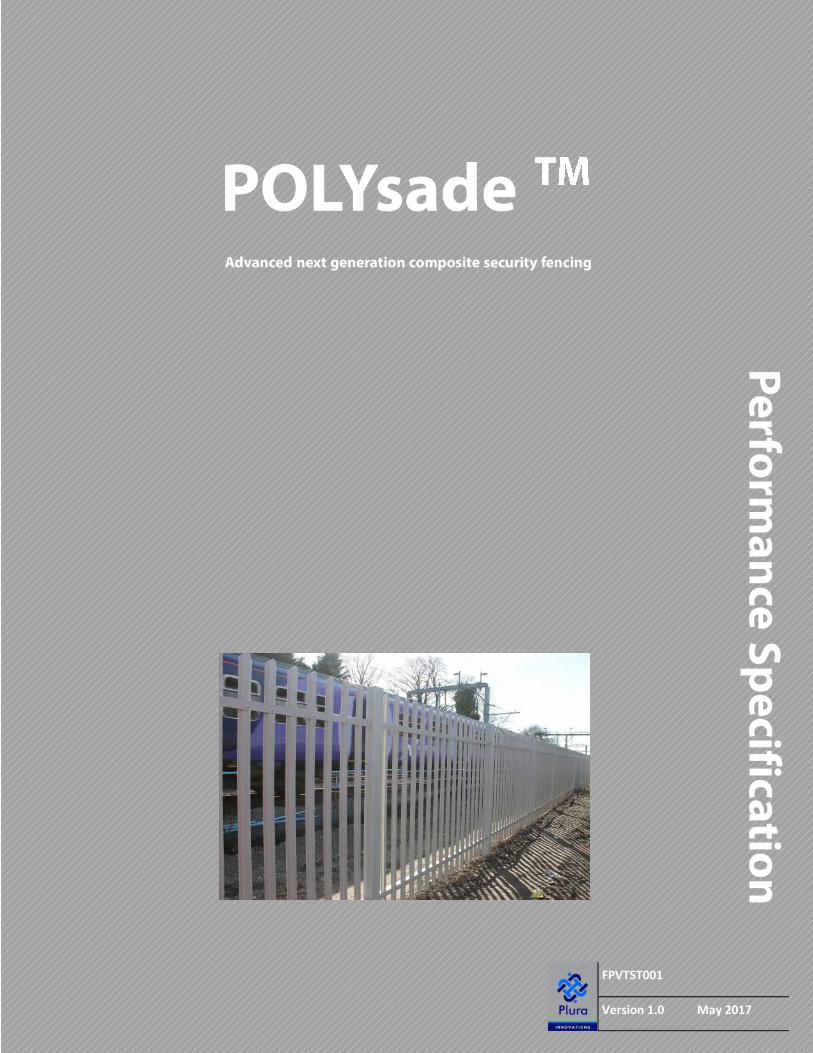
FPVTST001
Version 1.0 May 2017

PLURA STANDARD
Contents Foreword 2
1 Scope 3
2 Normative references 4
Section 1: Product Details 5
3 Dimensions and general characteristics 5
4 Materials 9
5 Construction of the fence 12
6 Security purpose (SP) fences 15
7 Maintenance, renovation and repair of composite GRP fences 15
8 Construction of gates 17
9 Options and accessories 22
Section 2: Installation 24
10 Installation 24
11 Statement of conformity 26
Section 3: Testing 27
12 Test A Flexural strength of pales 27
13 Test B Flexural strength of posts 29
14 Test C Flexural strength of rails 32
15 Test D Punch shear through strength of fixings to fishtail 35
Annexes
Annex E (informative) Specifying a composite GRP palisade fence 36
Annex F Standard Detail Drawings 38
FPVTST001 MAY2017
© PLURA Innovations 2017 PAGE 1

PLURA STANDARD
Foreword Document layout information
This specification is based upon the layout of British Standard BS 1722-12:2016 and it came into effect on 1 May 2017.
It was prepared by Graeme Pringle Technical Director for PLURA Composites Limited and authored by Andrew Wright Business Development Director for PLURA Composites Limited
Use of this document
It has been assumed in the preparation of this Specification that the execution of its provisions will be entrusted to appropriately qualified and experienced people. At the time of publication two appropriate qualification schemes are available: the Fencing Industry Skills Scheme (FISS) and the Construction Skills Certification Scheme (CSCS). 1) FISS/CSCS maintain a national register for fence installers and operatives. Other schemes might be available.
Copyright
This document is the copyright of PLURA Composites Limited
FPVTST001 MAY2017
© PLURA Innovations 2017 PAGE 2

PLURA STANDARD
1 Scope In the absence of any published standards for Composite GRP fencing: This specification is based upon BS 1722-12:2016, which specifies requirements for steel palisade fences and gates for general purpose (GP) fences for heights up to 2.4 m, and for security purpose (SP) fences for heights of 3 m and 3.6 m, all with posts at 2.75 m centres. The British Standard also covers fences between 2.4 m and 3 m in height with components constructed to the SP specification.
Please note however that due to the disparity in material properties and post construction; elements of BS 1722-12:2016 do not apply or are not appropriate when considering the performance criteria. This includes weight, deflection, certain key dimensions, material grades and corrosion resistance and these will be noted where applicable. However wherever appropriate; the load resistance requirements under test are still considered applicable. In addition; any features which are considered to be an essential function of the product.
NOTE 1 Where greater resistance against penetration is required for fences below 2.4 m in height, the SP components can be obtained from PLURA.
NOTE 2 Requirements within the British Standard for the minimum sizes of fence components are based on a design wind loading, q, at right angles to the plane of the fence of 900 N/m2 employing a shape factor of 1.9 on the net area presented to the wind.
NOTE 3 In situations of extreme exposure or abnormal loading, a special appraisal can be undertaken by PLURA based upon design criteria, which should be provided by the specifier/designer.
NOTE 4 The responsibility for ensuring the final installation meets this specification belongs to the installer. This responsibility can be mitigated by obtaining the following from PLURA, available upon request and which can be provided at the time of delivery (These are in accordance with Clause 10 of BS 1722-12:2016):
A. A certificate of conformity to this specification reference; FPVTST001 MAY2017
B. A Delivery note which contains: PLURAs contact details, a contract or order number, the date of delivery and the purchasers contact details
FPVTST001 MAY2017
© PLURA Innovations 2017 PAGE 3

PLURA STANDARD
2 Normative references The following documents, in whole or in part, are normatively referenced in this document and are indispensable for its application. For dated references, only the edition cited applies. For undated references, the latest edition of the referenced document (including any amendments) applies.
BS EN 13706—1:2002 Reinforced plastics composites. Specifications for pultruded profiles. Designation
BS EN 13707—2:2002 Reinforced plastics composites. Specifications for pultruded profiles. Method of test and general requirements
BS EN 13707—3:2002 Reinforced plastics composites. Specifications for pultruded profiles.
BS 907, Specification for dial gauges for linear measurement 2)
BS 3692:2014, ISO metric precision hexagon bolts, screws and nuts – Specification
BS 3693, Recommendations for design of scales and indexes on analogue indicating instruments
BS 4320, Specification for metal washers for general engineering purposes – Metric series
BS 4484-1, Specification for measuring instruments for constructional works – Part 1: Metric graduation and figuring of instruments for linear measurement
BS 7371-3, Coatings on metal fasteners – Part 3: Specification for electroplated zinc coatings
BS 7371-6, Coatings on metal fasteners – Part 6: Specification for hot dipped galvanized coatings
BS 8500-1:2015+A1:2016, Concrete – Complementary British Standard to BS EN 206 – Part 1: Method of specifying and guidance for the specifier
BS 8500-2:2015+A1:2016, Concrete – Complementary British Standard to BS EN 206 – Part 2: Specification for constituent materials and concrete
BS EN 1011-1, Welding – Recommendations for welding of metallic materials – Part 1: General guidance for arc
BS EN 1011-2, Welding – Recommendations for welding of metallic materials – Part 2: Arc welding of ferritic steels
BS EN 12620, Aggregates for concrete
BS EN ISO 376, Metallic materials – Calibration of force-proving instruments used for the verification of uniaxial testing machines
BS EN ISO 1461:2009, Hot dip galvanized coatings on fabricated iron and steel articles – Specifications and test methods
BS EN ISO 7500-1:2015, Metallic materials – Calibration and verification of static uniaxial testing machines – Part 1: Tension/compression testing machines –
Calibration and verification of the force-measuring system
BS 476-7: 1997 Class 2, Classification of spread of flame
FPVTST001 MAY2017
© PLURA Innovations 2017 PAGE 4
PLURA STANDARD
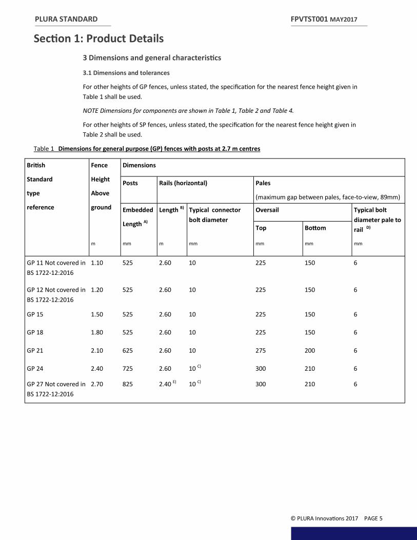
Section 1: Product Details 3 Dimensions and general characteristics
3.1 Dimensions and tolerances
For other heights of GP fences, unless stated, the specification for the nearest fence height given in Table 1 shall be used.
NOTE Dimensions for components are shown in Table 1, Table 2 and Table 4.
For other heights of SP fences, unless stated, the specification for the nearest fence height given in Table 2 shall be used.
Table 1 Dimensions for general purpose (GP) fences with posts at 2.7 m centres
FPVTST001 MAY2017
© PLURA Innovations 2017 PAGE 5
British
Standard
type
reference
Fence
Height
Above
ground
Dimensions
Posts Rails (horizontal) Pales
(maximum gap between pales, face-to-view, 89mm)
Embedded
Length A)
Length B) Typical connector bolt diameter
Oversail Typical bolt diameter pale to rail D) Top Bottom
m mm m mm mm mm mm
GP 11 Not covered in BS 1722-12:2016
1.10 525 2.60 10 225 150 6
GP 12 Not covered in BS 1722-12:2016
1.20 525 2.60 10 225 150 6
GP 15 1.50 525 2.60 10 225 150 6
GP 18 1.80 525 2.60 10 225 150 6
GP 21 2.10 625 2.60 10 275 200 6
GP 24 2.40 725 2.60 10 C) 300 210 6
GP 27 Not covered in BS 1722-12:2016
2.70 825 2.40 E) 10 C) 300 210 6
PLURA STANDARD
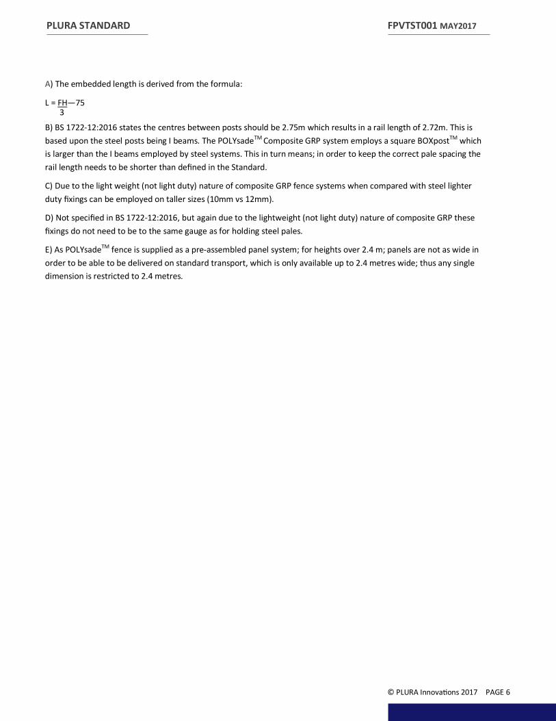
A) The embedded length is derived from the formula:
L = FH—75 3 B) BS 1722-12:2016 states the centres between posts should be 2.75m which results in a rail length of 2.72m. This is based upon the steel posts being I beams. The POLYsadeTM Composite GRP system employs a square BOXpostTM which is larger than the I beams employed by steel systems. This in turn means; in order to keep the correct pale spacing the rail length needs to be shorter than defined in the Standard.
C) Due to the light weight (not light duty) nature of composite GRP fence systems when compared with steel lighter duty fixings can be employed on taller sizes (10mm vs 12mm).
D) Not specified in BS 1722-12:2016, but again due to the lightweight (not light duty) nature of composite GRP these fixings do not need to be to the same gauge as for holding steel pales.
E) As POLYsadeTM fence is supplied as a pre-assembled panel system; for heights over 2.4 m; panels are not as wide in order to be able to be delivered on standard transport, which is only available up to 2.4 metres wide; thus any single dimension is restricted to 2.4 metres.
FPVTST001 MAY2017
© PLURA Innovations 2017 PAGE 6

PLURA STANDARD
Table 2 Dimensions for security purpose (SP) fences with posts at 2.7 m centres
A) The embedded length is derived from the formula:
L = FH—75 3 B) BS 1722-12:2016 states the centres between posts should be 2.75m which results in a rail length of 2.72m. This is based upon the steel posts being I beams. The POLYsadeTM Composite GRP system employs a square BOXpostTM which is larger than the I beams employed by steel systems. This in turn means; in order to keep the correct pale spacing the rail length needs to be shorter than defined in the Standard.
In addition (and in this case) as POLYsadeTM fence is supplied as a pre-assembled panel system; for the taller SP types, panels are not as wide in order to reduce the weight to a manageable level for manual handling. Also standard transport is only available up to 2.4 metres wide and so any single dimension is restricted to 2.4 metres.
C) Due to the light weight (not light duty) nature of composite GRP fence systems when compared with steel lighter duty fixings can be employed on taller sizes (10mm vs 12mm).
D) Not specified in BS 1722-12:2016, but again due to the lightweight (not light duty) nature of composite GRP these fixings do not need to be to the same gauge as for holding steel pales.
FPVTST001 MAY2017
© PLURA Innovations 2017 PAGE 7
British
Standard
type
reference
Fence
Height
Above
ground
Dimensions
Posts Rails (horizontal) Pales
(maximum gap between pales, face-to-view, 89mm)
Embedded
Length A)
Length B) Typical connector bolt diameter
Oversail Typical bolt diameter pale to rail D) Top Bottom
m mm m mm mm mm mm
SP 30 3.0 925 2.00 10 475 380 6
SP 36 3.60 1125 1.5 10 C) 650 550 6

PLURA STANDARD
3.2 Characteristics of pales
When tested in accordance with Test A Flexural strength of pales; pales shall conform to the load/ deflection as follows:
a) for SP fencing, as per BS 1722-12:2016 under test the load shall be 3.5 kN the maximum deflection at the middle of the span under a test load shall be 3.5 kN shall not exceed 24 mm A) (Steel is 10mm) ; and
b) for GP fencing, the maximum deflection at the middle of the span under a test load of 2.5 kN shall not exceed 15 mm A) (Steel is 8mm).
Pales shall also be capable of withstanding the loading for the pale to fence rail assembly in 5.2.
Pales shall be manufactured from Composite GRP to Grade E17 referenced within the standards in 4.1.
A) As BS 1722-12:2016 is designed for steel which, reaches it’s permanent set at much lower levels than GRP, the maximum deflection allowable has to be set at numbers much lower than for GRP. To balance this there is zero permanent set allowable with the GRP after the load is removed.
3.3 Characteristics of posts
When tested in accordance with Test B Flexural strength of posts; posts shall conform to the load deflection as follows:
a) for GP fencing posts, the maximum deflection at the middle of the 2 500 mm span under a test load of 10 kN shall not exceed 16 mm A) (Steel is also 16mm); and
b) for SP fencing posts, the maximum deflection at the middle of the 2 500 mm span under a test load of 20 kN shall not exceed 32 mm A) (Steel is 9mm).
The test load shall be applied to the post at right angles to the plane of the fence.
Posts shall be provided at a maximum of 2.7 m centres.
Posts shall be manufactured from Composite GRP to Grade E23 referenced within the standards in 4.1. A) As BS 1722-12:2016 is designed for steel which, reaches it’s permanent set at much lower levels than GRP, the maximum deflection allowable has to be set at numbers much lower than for GRP. To balance this there is zero permanent set allowable with the GRP after the load is removed.
B) As the POLYsadeTM is a pale pass through system; the rail is tested with the pale slots made into it.
FPVTST001 MAY2017
© PLURA Innovations 2017 PAGE 8

PLURA STANDARD
4 Materials
4.1 Glass Re-enforced Polyester Resin (GRP)
All GRP components conform to BS EN 13706 which defines the minimum mechanical properties in each of two grades E17 and E23.
The standard applies solely to pultruded profiles for “structural purposes”, which according to the standard are defined as “where the load-bearing characteristic is the major criterion of design and where the product is part of a load-bearing system”.
The standard specifies the minimum requirements for the quality, tolerances, strength, stiffness and surface of structural profiles.
Table 3 Mechanical properties
NOTE Where applicable, the use of higher strength or more enhanced grades than those shown is permissible, provided they meet the necessary requirements as in the standards listed in this table.
4.1.1 UV Properties
POLYsadeTM fencing is manufactured using Isophthalic Polyester Resin, which has a good resistance to UV. Additionally; additives and pigments which also contain ultraviolet light absorbers and inhibitors greatly increase the performance versus long term sunlight exposure.
Polyester synthetic veils are also applied to the outside of the profiles used in order to encapsulate the E-glass fibres and provide a resin rich surface, which limits the potential for glass show through (a common issue with earlier and aged GRP components installed outdoors).
Results have shown that UV degradation does not affect the modulus of elasticity of the profiles and so has limited effect on the mechanical properties of the fencing over time.
FPVTST001 MAY2017
© PLURA Innovations 2017 PAGE 9
Characteristic properties Minimum requirements
Property Unit Test method E23 E17
Modulus of elasticity GPa Annex D, EN 13706-2:2002 23 17
Tensile modulus-longitudinal GPa EN ISO 527-4 23 17
Tensile modulus-transverse GPa EN ISO 527-4 7 5
Tensile strength-longitudinal MPa EN ISO 527-4 240 170
Tensile strength-transverse MPa EN ISO 527-4 50 30
Pin bearing strength-longitudinal MPa Annex E,
EN 13706-2:2002
150 90
Pin bearing strength– transverse MPa Annex E,
EN 13706-2:2002
70 50
Bending strength-longitudinal MPa EN ISO 14125 240 170
Bending strength-transverse MPa EN ISO 14125 100 70
Shear strength-longitudinal MPa EN ISO 14130 25 15
PLURA STANDARD
Fading of the resin colour will occur although the extent of this is dependent upon the level and intensity of sunlight exposure. Further surface coating can be applied to significantly limit this effect should this be required, this should be specified by the designer / client.
4.1.2 Fire Resistance Properties
POLYsadeTM fencing conforms with BS 476-7: 1997 Class 2 as standard. Material can be formulated to produce a higher class if required.
POLYsadeTM material will not melt and will not fuel a fire.
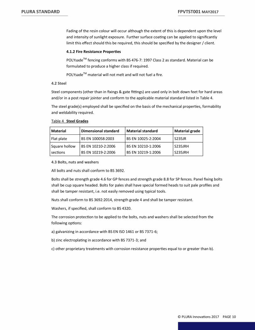
4.2 Steel
Steel components (other than in fixings & gate fittings) are used only in bolt down feet for hard areas and/or in a post repair jointer and conform to the applicable material standard listed in Table 4.
The steel grade(s) employed shall be specified on the basis of the mechanical properties, formability and weldability required.
Table 4 Steel Grades
4.3 Bolts, nuts and washers
All bolts and nuts shall conform to BS 3692.
Bolts shall be strength grade 4.6 for GP fences and strength grade 8.8 for SP fences. Panel fixing bolts shall be cup square headed. Bolts for pales shall have special formed heads to suit pale profiles and shall be tamper resistant, i.e. not easily removed using typical tools.
Nuts shall conform to BS 3692:2014, strength grade 4 and shall be tamper resistant.
Washers, if specified, shall conform to BS 4320.
The corrosion protection to be applied to the bolts, nuts and washers shall be selected from the following options:
a) galvanizing in accordance with BS EN ISO 1461 or BS 7371-6;
b) zinc electroplating in accordance with BS 7371-3; and
c) other proprietary treatments with corrosion resistance properties equal to or greater than b).
FPVTST001 MAY2017
© PLURA Innovations 2017 PAGE 10
Material Dimensional standard Material standard Material grade
Flat plate BS EN 100058:2003 BS EN 10025-2:2004 S235JR
Square hollow sections
BS EN 10210-2:2006 BS EN 10219-2:2006
BS EN 10210-1:2006 BS EN 10219-1:2006
S235JRH S235JRH
PLURA STANDARD
4.4 Cold swaged pin and collar fixings
Cold swaged collar grooved or grooved fasteners shall conform to BS 7805-1, and shall be formed from carbon boron steel conforming to BS EN 10263-1, BS EN 10263-2, BS EN 10263-3 and BS EN 10263-4, or equivalent, having a minimum tensile strength of 850 N/mm2. They shall have a suitably formed head and shall be provided with a ductile flanged collar.
NOTE Head types differ between manufacturers.
The tensile strength of cold swaged pin and collar fixings shall be determined in accordance with Test D.
The corrosion protection to be applied to the cold swaged pin and collar fixings shall be selected from the following options:
a) galvanizing in accordance with BS EN ISO 1461 or BS 7371-6;
b) zinc electroplating in accordance with BS 7371-3; and/or
c) other proprietary treatments with corrosion resistance properties equal to or greater than b).
FPVTST001 MAY2017
© PLURA Innovations 2017 PAGE 11
PLURA STANDARD
5 Construction of the fence
5.1 Pales
Pales are fixed to the horizontal rails such that the maximum gap between, face-to-view, is:
a) 89 mm for GP fences; and
b) 86 mm for SP fences.
The clear distance between pales and adjacent posts should not exceed the spacing between pales on adjacent fencing.
For both the GP and SP fences, pales pass through a CNC machined slot in the horizontal rails and are then secured to the rails at every intersection by use of a shear nut or cold swaged pin and collar fixings.
The heads of all fastenings have the minimum possible projection beyond the face of the pale to minimize tampering and footholds.
The pass through pale design provides protection against pale removal even in the event of direct impact attack on the fastener head.
The tolerance on the length of the pale shall be ±5 mm.
NOTE 1 Special gradient pale and rail fixings are available to deal with slopes.
NOTE 3 The shape of the tops of the pales should be specified by the purchaser.
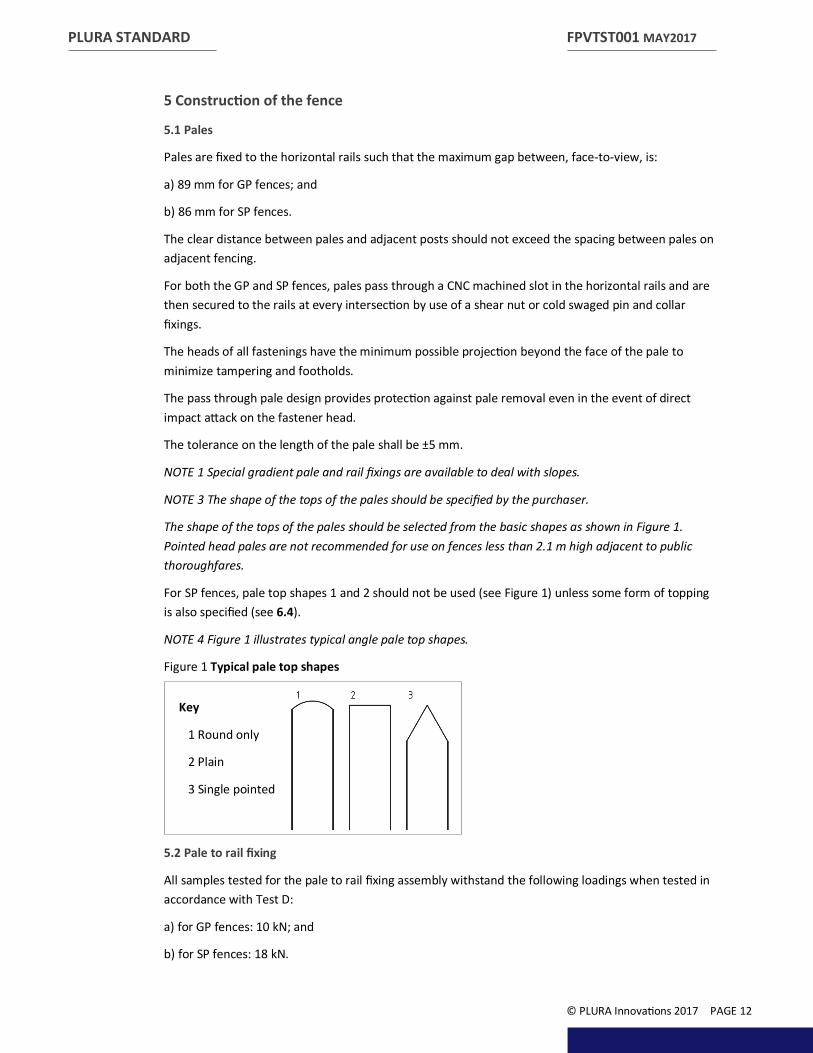
The shape of the tops of the pales should be selected from the basic shapes as shown in Figure 1. Pointed head pales are not recommended for use on fences less than 2.1 m high adjacent to public thoroughfares.
For SP fences, pale top shapes 1 and 2 should not be used (see Figure 1) unless some form of topping is also specified (see 6.4).
NOTE 4 Figure 1 illustrates typical angle pale top shapes.
Figure 1 Typical pale top shapes
5.2 Pale to rail fixing
All samples tested for the pale to rail fixing assembly withstand the following loadings when tested in accordance with Test D:
a) for GP fences: 10 kN; and
b) for SP fences: 18 kN.
FPVTST001 MAY2017
© PLURA Innovations 2017 PAGE 12
Key
1 Round only
2 Plain
3 Single pointed

PLURA STANDARD
5.3 Posts
Posts should be installed at a maximum of 2.7 m centres.
All posts are capped off at the top with a cap that does not protrude beyond the outer 100mm x 100mm size of the post.
Where posts are required at different centres, the centres should be specified by the client and all components will be purpose designed.
Posts should be embedded in concrete foundations to the minimum depths given in Table 1 and Table 2. 100mm diameter securing holes in opposing sides at the bottom of the BOXpostTM are in place so the concrete surround can be worked into the post base.
Where removable lengths of palisade fence are required, the construction details or design criteria for the removable posts and their foundations should be specified; See the removable insert in 9. Options and accessories to assist with this.
5.4 Stays
If stays are necessary to withstand abnormal loading or site conditions, the design criteria or constructional details of the stays should be specified between PLURA and the client.
NOTE 1 The fences specified by BS 1722-12:2016 are designed to be used without stays.
NOTE 2 All SP fences in POLYsadeTM have anti burrowing measures as laid out in 6.2
5.5 Rails
Fences have a minimum of two horizontal rails.
NOTE For SP fences, additional rails can be added by agreement between the purchaser and PLURA (see Clause 6).
Each rail is secured to posts with connector plates or fish plates bolted to the vertical leg(s) of the rail.
NOTE 1 For SP fences; BS 1722-12:2016 calls for fish plates or connector plates to be fitted to the web of the post. Due to the BOXpostTM nature of the POLYsadeTM system; this is not possible; as the fishtail passes through two walls in the POLYsade TM system; this is already inherently stronger and more secure than standard GP steel systems.
The diameter of the bolts is as given in Table 1 and Table 2.
NOTE 2 BS 1722-12:2016 calls for provision to be made for thermal expansion by providing slotted holes at the rail to plate connection. As thermal expansion of composite material is minimal when compared to steel this is not applicable.
Plates are a minimum of 6 mm thick, and of sufficient sizing to give a minimum distance of 9 mm to the edge of the hole.
Connector plates or fish plates are not connected to the post but instead pass through the twin walls of the BOXpostsTM. This can be enhanced by provision of a security bolt which passes through the BOXpostTM perpendicular to the connector plate. It passes through the two walls of the BOXpostTM and through the connector plate within the post. This then complies with 5.6 a) & c) within the BS 1722-12:2016 standard but is an option only and requires specification by the client.
FPVTST001 MAY2017
© PLURA Innovations 2017 PAGE 13

PLURA STANDARD
5.6 Post to rail connections
Each rail is secured to posts with connector plates or fish plates bolted to the front vertical leg of the rail. As the POLYsadeTM fishtail is made from extra thick GRP plate which passes through two walls of the BOXpostTM; for SP fences, there is no requirement for the fish plate or a connector plate to be fitted to the web of the post. The diameter of the bolts shall be as given in Table 1 and Table 2. There is no provision required for thermal expansion as GRP is not affected like steel. Slotted holes are provided at the rail to plate connection to allow for an easier site fix. Plates are a minimum of 8 mm thick, and of sufficient sizing to give a minimum distance of 9 mm to the edge of the hole.
Connector plates or fish plates are connected to the post by passing through pre-machined slots in two walls of the BOXpostTM.
This can be enhanced by provision of a security bolt which passes through the BOXpostTM perpendicular to the connector plate. It passes through the two walls of the BOXpostTM and through the connector plate within the post.
NOTE: Standard posts are ‘pass through’ in line run and have slots top and bottom on opposing faces to accept the fishtail. The client must specify at time of order; any posts which are required on a corner or end of run as these will be either machined on perpendicular or a single face(s).
Figure 2 Fishtail configurations
5.7 Intermediate supports
Where appropriate, intermediate supports will be provided to the lower structural rail in order to prevent the rail deflecting in excess of 10 mm (at any point) under the weight of the fence. As POLYsadeTM is much lighter than the steel alternative; this measure will only be required in minimal cases.
5.8 Protective treatment
Composite GRP material will not corrode and so the measures contained within Section 1 5.8 of BS 1722-12:2016 for protective treatment are not applicable.
All profiles used within the fencing are produced using UV stable materials (see 4.1.1).
FPVTST001 MAY2017
© PLURA Innovations 2017 PAGE 14
Key
1 180 degree pass through 2 Terminating end of run 3 90 degree pass through 4 Step up/down
1 2 3 4

PLURA STANDARD
6 Security purpose (SP) fences
6.1 General
Additional security measures will be taken for all SP fences.
NOTE These measures are optional for GP fences.
6.2 Burrowing
If burrowing is possible, one of the following measures should be specified under BS 1722-12:2016:
a) a concrete sill shall be provided in accordance with 9.1.3;
b) pales shall be extended by 150 mm and embedded in the concrete sill as in a); or
c) pales shall be extended by 350 mm and buried in the ground. A)
A) By far the simplest and most practical approach with POLYsadeTM is c) Composite GRP is non- corrosive and therefore has a design life in excess of 60 years even if c) is undertaken. Buried pales will not corrode and this eliminates the need for wet-trades on site.
6.3 Increased resistance to penetration
To increase resistance to pale removal, and if the pales are not buried or set in concrete in accordance with 6.2, an additional rail can be attached to the lower part of each pale. This additional rail will be fixed to the pales 100 mm from the bottom of the pale.
NOTE To increase resistance to penetration additional rails can be added, for example, at waist height, by agreement with the designer.
6.4 Topping
If required, further security against climbing shall be provided by fixing a spiked topping, barbed wire entanglement or barbed tape concertina to the pales.
Such toppings shall be fitted as close to the top of the pales as possible or, in the case of barbed coils, the wire shall sit within the oversail.
NOTE The use of such toppings on SP fences is highly recommended. However, the use of barbed tape concertina is not recommended for fences below 3 m in height as the bottom of the coil should not be less than 2.5 m above ground level.
7 Maintenance, renovation and repair of composite GRP fences
The fence should be inspected after installation and on a regular basis as part of any standard asset maintenance program. If damage is found; depending upon the nature; the following actions should be taken:
7.1 Damage to the structure (for example from being hit by a vehicle or similar)
In the unlikely event that a part of the fence becomes damaged during installation the damaged part must be removed and replaced to keep the integrity of the system. This is the same if damage occurs post installation.
FPVTST001 MAY2017
© PLURA Innovations 2017 PAGE 15

PLURA STANDARD
7.2 Deep scratches
These may be more noticeable on darker colours of Black or Dark Green.
Use the PLURA POLYsadeTM Fence Smart Paint Scratch Repair Remover touch up pen, available in standard colours of Black, Holly Green and Blue.
Full instructions are supplied with the pen.
This paint has been specially chosen as it perfectly compliments the composite GRP materials used, requires minimum preparation, will NOT delaminate or flake and will match the design life of the fencing product.
NOTE On White and Standard Grey fences these will not be noticeable.
7.3 Surface/Superficial scratches
These can be removed by use of a proprietary ‘Back to Black’ type cleaner.
7.4 General cleaning
It is safe to use any standard soap and water and/or jet washing to clean POLYsadeTM fencing.
FPVTST001 MAY2017
© PLURA Innovations 2017 PAGE 16

PLURA STANDARD
8 Construction of gates
8.1 General
Gates provide a comparable degree of security to the adjacent fencing. The overall height of the gates when fixed is not less than the adjacent fencing height. The top and bottom rails of the gates are set at the same level as the fence rails.
The gates are designed so that the distance from the bottom edge of the gate pales to the surface of the road/path/ground does not exceed 70 mm when the gate is in the closed position.
The spacing of pales on the gates is the same as that used on the fencing. The clear distance between the vertical framing of the gates and adjacent posts or pales is not greater than the clear distance between pales on the adjacent fencing.
All gate frames are produced from box section the size for which is given in Table 5. Joints for the gate frame are internally re-enforced with in-house produced Polyurethane angle blocks, which are bonded into the box section joints and are then bolted through as a secondary fix.
NOTE 1 As composite GRP materials are much lighter than steel; this results in a lighter gate and as such the gate frame box sections can be a lighter gauge than those set out for steel with BS 1722- 12:2016 (This is allowable within the standard if agreed by the client).
NOTE 2 The section sizes for gate frames are given in Table 5.
To provide rigidity and to limit deflection and sag in service:
A) As per BS 1722-12:2016 ‘Where pales are not welded they shall be attached by the same method as fence pales’. As such all pales are of the same ‘pass thru’ and bolted nature as for the fence panels; &
B) To further improve rigidity; rear mounted corner frame fillets can be added on larger spanning gates (1.5m plus) or if requested by the client.
As is required by BS 1722-12:2016:
The methods in A) and B) affords the same resistance to penetration as the fence.
There are no footholds between the top and bottom horizontal rails of the gate.
Cross-bracing is not used.
FPVTST001 MAY2017
© PLURA Innovations 2017 PAGE 17

Fence height
Typical frame sizes for individual gate leaf widths
<1.5m >1.5m <2.0m
>2.0m <3.0m
m mm mm mm
1.1 50x50x5 50x50x5 50x50x5
1.2 50x50x5 50x50x5 50x50x5
1.5 50x50x5 50x50x5 50x50x5
1.8 50x50x5 50x50x5 50x50x5
2.1 50x50x5 50x50x5 50x50x5
2.4 50x50x5 50x50x5 50x50x5
2.7 50x50x5 50x50x5 75x75x6
3.0 50x50x6 50x50x6 75x75x6
3.6 50x50x6 75x75x6 75x75x6
PLURA STANDARD
Table 5 Frame sizes for individual gate leaf widths (pairs or singles)
NOTE Where the clear opening of a gateway is critical this should be specified by the client
8.2 Hinges
8.2.1 Hinges general
Due to the lightweight nature of composite GRP fencing and gates, POLYsadeTM pedestrian access gates can feature ‘Self closing’ hinges in addition the traditional ‘Pin and eyebolt’ hinges.
8.2.2 Hinge safety
Gates are designed such that failure of a single hinge does not allow the gate to fall.
Hinges and gate posts are designed to take the full load of the gate plus an allowance for superimposed vertical loads equal to 100 kg applied at the nose of the gate without deflection in any position detrimental to its operation.
Each hinge mechanism is designed to bear a load equal to 3.5 times the weight of the finished gate leaf.
NOTE 1 Typical dimensions of hinge components are given in Table 6. NOTE 2 As with other parts of the Composite GRP system; the gates are much lighter than steel and therefore fixing components can be of lighter gauge.
FPVTST001 MAY2017
© PLURA Innovations 2017 PAGE 18

PLURA STANDARD
Table 6 Fitting requirements for gates
Table 7 Typical minimum dimensions for gate fittings
FPVTST001 MAY2017
© PLURA Innovations 2017 PAGE 19
Fence height Fitting schedule category
For single gates For pairs of gates
0.9m to 1.2m wide
4m to 5.8m wide
>5.8m wide
1.1m to 2.1m A B C
2.4m to 2.7m A C E
3.0m to 3.6m C E E
Description Dimensions
Schedule A Schedule B Schedule C Schedule E
mm mm mm mm
Hinge pins diameter N/A 20 30
By special design only
Pivot bolt diameter N/A 20 30
Gate eye bolt:
Eye thickness N/A 20 30
Bolt diameter N/A 20 30
Lugs:
Single N/A 20 30
Double N/A 20 20
Backing plate thickness 10 12 12
Bolt diameter for connecting backing plate to gate posts
4 x 16 4 x 20 4 x 20
Drop bolt diameter 20 22 22
Locking bar 50 x 10 50 x 10 50 x 10
Self Closing Hinges Truclose Series 3 Heavy Duty Standard
N/A N/A
Slam plate 6 8 8

PLURA STANDARD
8.2.3 Hinges and security
Hinges used are designed so that it is impossible to remove the gates by lifting at the hinges when they are in the shut and locked position. The hinges are provided with a simple and easily applied system of adjustment for the correction of sag, settlement or misalignment during installation and service.
NOTE 1 See Figure 3 for an example of a hinge eyebolt fitted to composite GRP post and gate frame. NOTE 2 See Figure 4 for an example of a Truclose Heavy duty Standard hinge.
Figure 3 Example of a hinge eyebolt
Figure 4 Example of Truclose Heavy duty hinge
FPVTST001 MAY2017
© PLURA Innovations 2017 PAGE 20
Key
1 Post
2 Gate frame
1
1
2
2
PLURA STANDARD
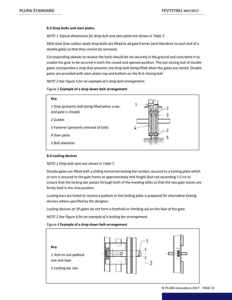
8.3 Drop bolts and slam plates
NOTE 1 Typical dimensions for drop bolt and slam plate are shown in Table 7.
Mild steel (low carbon steel) drop bolts are fitted to all gate frames (and therefore to each leaf of a double gate) so that they cannot be removed.
Corresponding sleeves to receive the bolts should be set securely in the ground and concreted in to enable the gate to be secured in both the closed and opened position. The last closing leaf of double gates incorporates a stop that prevents one drop bolt being lifted when the gates are closed. Double gates are provided with slam plates top and bottom on the first closing leaf.
NOTE 2 See Figure 5 for an example of a drop bolt arrangement.
Figure 5 Example of a drop down bolt arrangement
8.4 Locking devices
NOTE 1 Drop bolt sizes are shown in Table 7.
Double gates are fitted with a sliding horizontal locking bar section, secured to a locking plate which in turn is secured to the gate frame at approximately mid-height (but not exceeding 1.5 m) to ensure that the locking bar passes through both of the meeting stiles so that the two gate leaves are firmly held in the shut position.
Locking bars are holed to receive a padlock or the locking plate is prepared for alternative locking devices where specified by the designer.
Locking devices on SP gates do not form a foothold or climbing aid on the face of the gate.
NOTE 2 See Figure 6 for an example of a locking bar arrangement.
Figure 6 Example of a drop down bolt arrangement
FPVTST001 MAY2017
© PLURA Innovations 2017 PAGE 21
Key
1 Stop (prevents bolt being lifted when a sec-ond gate is closed)
2 Guides
3 Fastener (prevents removal of bolt)
4 Slam plate
5 Bolt diameter
Key
1 Hole to suit padlock size and type
2 Locking bar size

PLURA STANDARD
8.5 Gate posts
Hinges and gate posts are designed to take the full load of the gate plus an allowance for superimposed vertical loads equal to 100 kg applied at the nose of the gate without deflection in any position detrimental to its operation.
NOTE 1 Typical dimensions for gate posts are shown in Table 8 and Table 9.
NOTE 2 In calculating the dimensions, it has been assumed that the major axis of the post is perpendicular to the line of the fence.
9 Options and accessories
Along with the standard fence and gate system, a range of options and accessories are available to assist with installation and / or maintenance of the POLYsade TM.
9.1 Posts
9.1.1 Bolt down post feet
In areas where it is not possible to bury the base of posts / where the surface is a hard standing, bolt down fence post feet are available. Produced from galvanised steel, feet have an upstand which firmly fits inside of the BOXpostTM along with an external skirt which wraps around the outside. Posts are secured to the feet by bolts supplied with the feet.
Each foot has a base flange with 4 number M10 holes for bolting down.
NOTE Foundation bolts are not provided with the feet. As site conditions can vary; it is the responsibility of the installer / client to specify and source these as appropriate.
9.1.2 Removable posts
Should it be required to remove fence posts for future, temporary access to a part of the site; bolt on galvanised steel inserts, which sit inside the BOXpostsTM are available.
The installer shall cut the BOXpostTM, circa 100 to 150mm up from the finished ground level and perpendicular to the post. The steel insert then slides down inside the embedded post and is bolted into place. The top part of the post is then inserted over this fitting and bolted into place to create a finished post.
This process can be reversed in future to remove the post and adjacent panels.
NOTE 1 Adjacent panels should be fitted to the fishtails with removable bolts; these will be concealed at the rear on the fence inside the box rail.
NOTE 2 Bolts that secure the post to the steel fitting insert should be removable and utilise a security head to prevent un-authorised access.
9.1.3 Fishtail slots
For changes in the direction of a fence line, BOXpostTM fishtail slots can be machined to take the line at a 30 to 90 degree angle.
In addition slots can be machined into just one post side if the post is terminating a run.
Fishtail caps are available to cover any un-used slots.
FPVTST001 MAY2017
© PLURA Innovations 2017 PAGE 22

PLURA STANDARD
9.2 Gradients
Where the fence line will run along a slope; there are two options;
9.2.1 Stepped posts
Fishtail slots can be offset within BOXpostsTM to provide a stepped fixing of panels to follow the slope; the degree of slope / fall should be specified by the client at time of enquiry.
NOTE See 5.6 Figure 2 4.
9.2.2 Concertina panels
Panels with oversized slots for pass through rails and with ‘loose’ shear nut fixings of pale to rail arrangement allow the installer to concertina the panels at time of installation to suit the fall. This is useful if a stepped fence is not required or is the slope fall cannot be pre-determined by the client. A maximum 30cm in 2.7 metre panel fall is achievable.
9.3 Replacement components
Replacements are available for all parts of the POLYsadeTM fencing system. These include:
Posts, Post top Caps, Post fishtail caps;
Pales, Rails (pre-slotted to accept pales) & Centre Stays;
Fixings Rail to Fishtail, Fixings Pale to Rail and;
Gates, Gate hinges, Gate locks and catches
9.4 Touch up kits
As detailed in 7.2; POLYsadeTM Fence Smart Paint Scratch Repair Remover touch up pens are available in standard colours of Black, Holly Green and Blue.
Full instructions are supplied with the pen.
FPVTST001 MAY2017
© PLURA Innovations 2017 PAGE 23

PLURA STANDARD
Section 2: Installation 10 Installation
10.1 Foundation and sills
COMMENTARY ON 9.1
During gate installation, where ground conditions necessitate, a hard threshold should be used to prevent burrowing.
10.1.1 General
Foundations for SP fences and gates used shall be designed to take account of conditions of service if these give rise to loads in excess of the defined wind loads.
Posts for all composite palisade fences shall be set in concrete where appropriate. The presence of any electricity, gas, water or other underground services shall be established prior to commencement of excavation, drilling or installation in the working area.
10.1.2 Holes for fence post foundations
Unless specifically designed foundations are specified by the client, the dimensions in plan of the holes excavated to receive the posts shall conform to Table 9. The hole shall be formed, with vertical sides, to a depth below ground level equal to one third of the height of the fence above ground level.
Table 8 Holes for fence post foundations
NOTE These foundation sizes are based on the assumption of average ground conditions and wind loading. In abnormal conditions, conditions of extreme exposure or severe conditions of service, special measures might be required.
10.1.3 Concrete sills
Where a concrete sill is specified by the client, it shall be formed of in-situ concrete and shall be continuous between posts under the line of the pales. The sill shall be not less than 125 mm wide × 150 mm deep and cast with the top at, or within, 50 mm of ground level so that the distance between the underside of the pales and the top of the sill does not exceed 50 mm. If shuttering of the side or weathering of the top of the sill is required, this shall be specified.
NOTE As Composite GRP fencing will not corrode; to save ‘wet trades’ on site it is recommended to specify greater oversail to the bottom of the pales to 350mm and bury the pales into the ground. This as detailed in 6.2 c).
FPVTST001 MAY2017
© PLURA Innovations 2017 PAGE 24
Minimum plan dimensions Fence height above ground level Square hole Round hole
m mm mm
Less than 2.4 350 x 350 450 diameter
2.4 350 x 350 450 diameter
3 450 x 450 600 diameter
3.6 450 x 450 600 diameter

PLURA STANDARD
10.1.4 Concrete for post foundations and sills
Concrete for post foundations and sills shall be at least one part cement to ten parts 20 mm all-in ballast conforming to BS EN 12620 mixed with the minimum requisite quantity of clean water, or grade C8/10 or ST2 concrete conforming to BS 8500-1:2015+A1:2016 and BS 8500-2:2015+A1:2016. The concrete shall be placed in position before commencement of the initial set.
10.2 Line
The fence shall follow lines specified by the designer / client. The bottom of the pales shall be not more than 50 mm above mean ground level or concrete sill level.
The presence of any electricity, gas, water or other underground services shall be established prior to commencement of excavation, drilling or installation in the working area.
NOTE Unless otherwise agreed between the client and the installer; (see Annex A) the installation of the fence does not include work required to cut or fill the ground to vary levels, nor does it cover special work to secure culverts, ditches, etc.
10.3 Posts
Posts shall be fixed in a concrete base to the appropriate depth.
NOTE 1 The minimum quantity of water necessary depends on the moisture content of the ballast pri or to mixing.
Posts shall be vertical. The holes for the posts shall be filled to ground level, top of ground beam or road level with concrete which shall be rammed as the filling proceeds. Care and attention should be taken to make sure concrete is entered into the securing holes at the bottom of the BOXpostsTM as this will tie the post in securely to the base. The top of the concrete shall be weathered.
NOTE 2 See Table 8 for foundation sizes.
10.4 Posts for gates
Posts shall be fixed in a concrete base to the appropriate depth in accordance with Table 1 & Table 2 in terms of embedded depths and Table 8 in terms of concrete surround dimensions.
Posts shall be vertical. The hole for the posts shall be filled to ground level, top of ground beam or road level with concrete which shall be rammed as the filling proceeds. The top of the concrete shall be weathered.
10.5 Intermediate supports
Intermediate supports, where required, shall be embedded in concrete to a depth of 100 mm. The concrete shall be either a concrete sill as specified in 9.1 or a concrete base (150 × 150 × 150) mm deep with the top at ground level.
10.6 Fastenings
On completion, fastenings shall be secure and tamper resistant, i.e. not removed using easily obtainable tools.
FPVTST001 MAY2017
© PLURA Innovations 2017 PAGE 25

PLURA STANDARD
11 Statement of conformity 11.1 Fence installer
BS 1722-12:2016 requests that: On completion of any installation of fence , the fence installer shall provide the end user with a certificate, conforming to 10.2, confirming that the installation and materials used are in accordance with the British Standard, however, although POLYsadeTM and composite GRP materials do not fully comply with the standard; in lieu of this; the certificate shall confirm the installation and materials are in accordance with this specification FPVTST001.
NOTE 1 This certificate can be in the form of an invoice provided this conforms to 10.2.
The installer shall take responsibility for the materials used.
NOTE 2 On delivery, the installer can obtain a certificate/documentation from the PLURA, stating materials supplied are in accordance with this specification.
11.2 Certificate/documentation
In addition to the requirements of 10.1, the certificate/documentation shall also include the following information:
a) PLURAs’ name and address;
b) the contract or order number;
c) the date of delivery or installation;
d) the purchaser’s name and address.
Test reports shall be provided as part of the certificate in accordance with A.5, B.4 and C.4.
11.3 Statement
The installer shall make a written statement which details that it is their policy to conform to a previously agreed specification with the client and to offer goods and/or services accordingly. The installer shall obtain the same written statement from PLURA.
NOTE This might be done by inclusion in any trade advertising and/or any terms of trading statements supplied with quotations.
FPVTST001 MAY2017
© PLURA Innovations 2017 PAGE 26
PLURA STANDARD
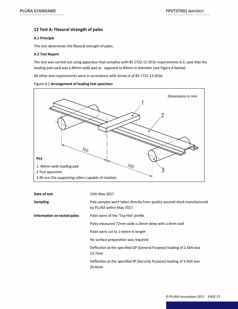
12 Test A: Flexural strength of pales A.1 Principle
This test determines the flexural strength of pales.
A.2 Test Report
The test was carried out using apparatus that complies with BS 1722-12:2016 requirements A.2, save that the loading pad used was a 40mm wide pad as opposed to 40mm in diameter (see Figure A below).
All other test requirements were in accordance with Annex A of BS 1722-12:2016.
Figure A.1 Arrangement of loading test specimen
Date of test 15th May 2017
Sampling Pale samples were taken directly from quality assured stock manufactured by PLURA within May 2017.
Information on tested pales Pales were of the ‘Top-Hat’ profile
Pales measured 72mm wide x 24mm deep with a 4mm wall
Pales were cut to 1 metre in length
No surface preparation was required
Deflection at the specified GP (General Purpose) loading of 2.5kN was 14.7mm
Deflection at the specified SP (Security Purpose) loading of 3.5kN was 20.6mm
FPVTST001 MAY2017
© PLURA Innovations 2017 PAGE 27
Dimensions in mm
Key
1. 40mm wide loading pad 2 Test specimen 3 40 mm Dia supporting rollers capable of rotation
PLURA STANDARD
Further testing Deflection at 5kN loading (Above requirements of BS 1722-12:2016) was 23.2mm
Ultimate failure load was 7kN.
Failure occurred in the form of splitting of the pale along the line of the glass rovings:
Ultimate failure load equated to 4375kN/m2
NOTE even at failure load; a failure of this nature would still not facilitate the removal of the pale from the rail nor allow for access through the pales.
Conclusion The POLYsadeTM pale profile is able to withstand a load 2.8 times the load specified for GP (General Purpose) fence within BS 1722-12:1026, although a greater deflection than maximum allowable in this; the steel standard occurs. The profile fully recovers and has no permanent set, unlike steel, which, would face permanent set and not recover when deflected beyond the 8 to 10mm allowable in the standard.
It should be noted that as this is the case the deflection allowable for steel cannot be taken into account when testing POLYsadeTM as the Pass/Fail criteria are different/not appropriate. POLYsadeTM is more than capable of withstanding the required load, i.e.; it is as strong as steel, it just performs differently.
FPVTST001 MAY2017
© PLURA Innovations 2017 PAGE 28

PLURA STANDARD
13 Test B: Flexural strength of posts B.1 Principle
This test determines the flexural strength of posts.
B.2 Test Report
The test was carried out using Finite Element Analysis (FEA). The 100mm x 100mm x 6mm BOXpostTM has a GPA of 42 which is in excess of the maximum 23GPA required by EN 13706 Reinforced plastics composites. Specifications for pultruded profiles.
Despite this fact; FEA was run based upon the lower 23GPA
BS 1722-12:2016 test method in Annex B allows the post to freely move at it’s ends on 40mm dia. rollers that are capable of rotation. This allows the ends of the post to deflect upwards when the test load is applied at the centre. For purposes of FEA this is not possible and the ends were in fact held in place. The effect of this creates a worse case scenario as the deflection in the centre is heightened and the stresses are greater as the post cannot flex as it would if rollers were used.
All other test requirements were in accordance with Annex B of BS 1722-12:2016.
Figure B.1 Arrangement of loading test specimen
Date of test 15th May 2017
Sampling Computer generated post is based upon BOXpostsTM manufactured by PLURA.
FPVTST001 MAY2017
© PLURA Innovations 2017 PAGE 29
Dimensions in mm
Key
1. Ends held fixed 2 40 mm Dia loading pad 3 Test section BOXpostTM 100x100x6

PLURA STANDARD
Information on tested post Post measured 100mm wide x 100mm deep with a 6mm wall
Post was 2.5 metres long
Deflection at the specified GP loading of 10kN was 15.2mm (simulated 79MPa)
Deflection at the specified SP loading of 20kN was 30.4mm (simulated 158MPa)
Conclusion As the materials ultimate failure load is 357MPa, (versus steel of 235MPa) the simulated loads of 79MPa and 158MPa are well within safety factors of 4.5 x and 2.3x accordingly.
FPVTST001 MAY2017
© PLURA Innovations 2017 PAGE 30
PLURA STANDARD
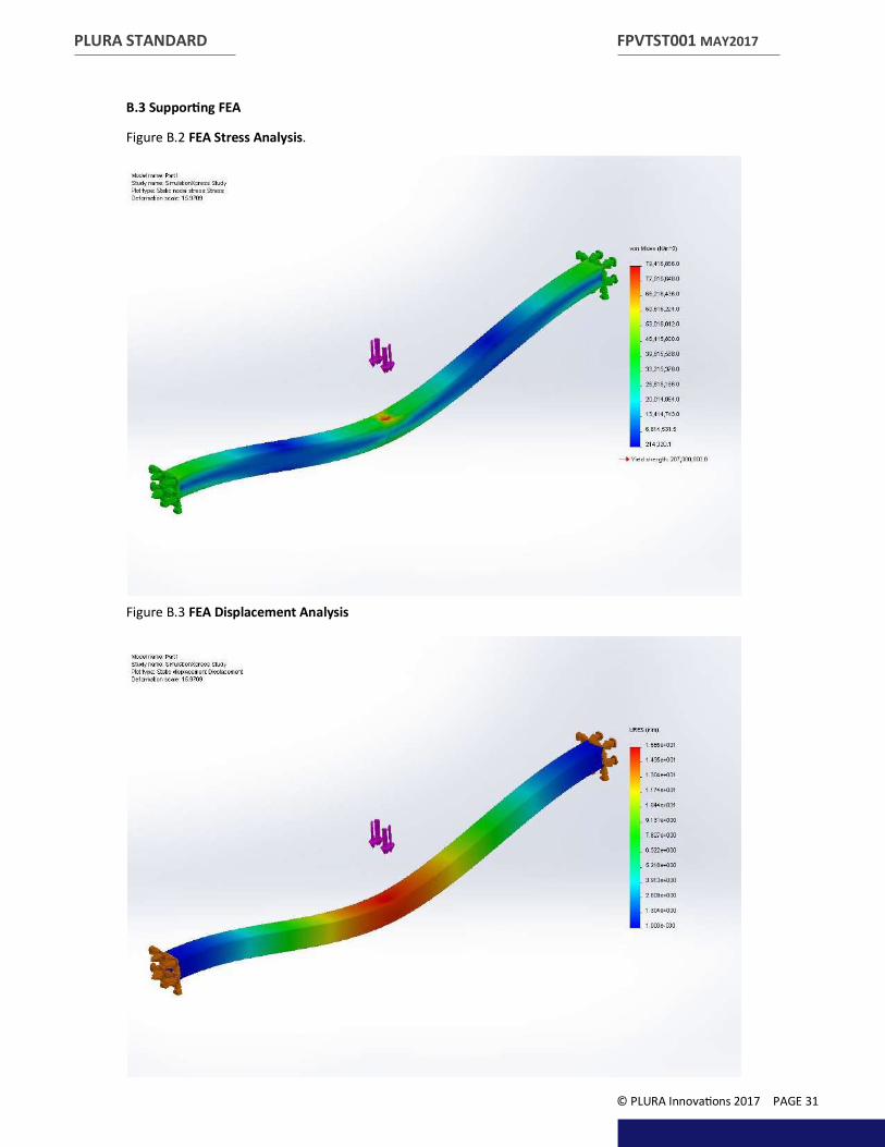
B.3 Supporting FEA
Figure B.2 FEA Stress Analysis.
Figure B.3 FEA Displacement Analysis
FPVTST001 MAY2017
© PLURA Innovations 2017 PAGE 31
PLURA STANDARD
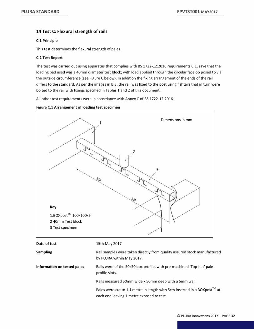
14 Test C: Flexural strength of rails C.1 Principle
This test determines the flexural strength of pales.
C.2 Test Report
The test was carried out using apparatus that complies with BS 1722-12:2016 requirements C.1, save that the loading pad used was a 40mm diameter test block; with load applied through the circular face op posed to via the outside circumference (see Figure C below). In addition the fixing arrangement of the ends of the rail differs to the standard; As per the images in B.3; the rail was fixed to the post using fishtails that in turn were bolted to the rail with fixings specified in Tables 1 and 2 of this document.
All other test requirements were in accordance with Annex C of BS 1722-12:2016.
Figure C.1 Arrangement of loading test specimen
Date of test 15th May 2017
Sampling Rail samples were taken directly from quality assured stock manufactured by PLURA within May 2017.
Information on tested pales Rails were of the 50x50 box profile, with pre-machined ’Top-hat’ pale profile slots.
Rails measured 50mm wide x 50mm deep with a 5mm wall
Pales were cut to 1.1 metre in length with 5cm inserted in a BOXpostTM at each end leaving 1 metre exposed to test
FPVTST001 MAY2017
© PLURA Innovations 2017 PAGE 32
Dimensions in mm
Key
1.BOXpostTM 100x100x6 2 40mm Test block 3 Test specimen
PLURA STANDARD
No surface preparation was required
Deflection at the specified GP (General Purpose) loading of 5kN was 16mm
Deflection at the specified SP (Security Purpose) loading of 5kN was 16mm
Conclusion The POLYsadeTM pass through rail is able to withstand the required loading required in BS 1722-12:1026, although a greater deflection than maximum allowable in this; the steel standard occurs. The profile fully recovers and has no permanent set, unlike steel, which, would face permanent set and not recover when deflected beyond the 5 to 12mm allowable in the standard.
It should be noted that as this is the case the deflection allowable for steel cannot be taken into account when testing POLYsadeTM as the Pass/Fail criteria are different/not appropriate. POLYsadeTM is more than capable of withstanding the required load, i.e.; it is as strong as steel, it just performs differently.
FPVTST001 MAY2017
© PLURA Innovations 2017 PAGE 33
PLURA STANDARD
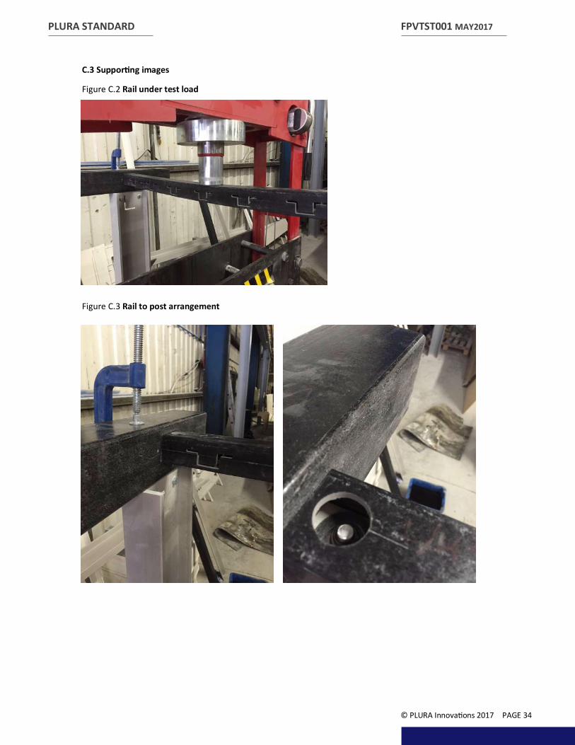
C.3 Supporting images
Figure C.2 Rail under test load
Figure C.3 Rail to post arrangement
FPVTST001 MAY2017
© PLURA Innovations 2017 PAGE 34
PLURA STANDARD
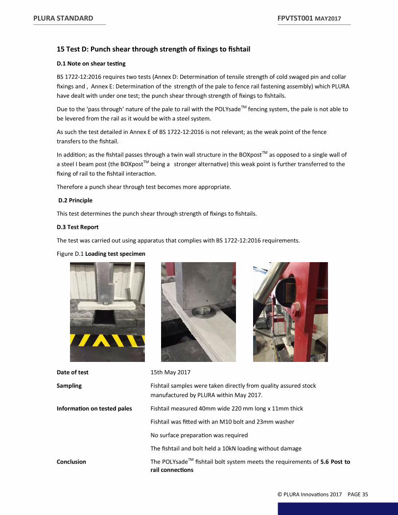
15 Test D: Punch shear through strength of fixings to fishtail D.1 Note on shear testing
BS 1722-12:2016 requires two tests (Annex D: Determination of tensile strength of cold swaged pin and collar fixings and , Annex E: Determination of the strength of the pale to fence rail fastening assembly) which PLURA have dealt with under one test; the punch shear through strength of fixings to fishtails.
Due to the ‘pass through’ nature of the pale to rail with the POLYsadeTM fencing system, the pale is not able to be levered from the rail as it would be with a steel system.
As such the test detailed in Annex E of BS 1722-12:2016 is not relevant; as the weak point of the fence transfers to the fishtail.
In addition; as the fishtail passes through a twin wall structure in the BOXpostTM as opposed to a single wall of a steel I beam post (the BOXpostTM being a stronger alternative) this weak point is further transferred to the fixing of rail to the fishtail interaction.
Therefore a punch shear through test becomes more appropriate.
D.2 Principle
This test determines the punch shear through strength of fixings to fishtails.
D.3 Test Report
The test was carried out using apparatus that complies with BS 1722-12:2016 requirements.
Figure D.1 Loading test specimen
Date of test 15th May 2017
Sampling Fishtail samples were taken directly from quality assured stock manufactured by PLURA within May 2017.
Information on tested pales Fishtail measured 40mm wide 220 mm long x 11mm thick
Fishtail was fitted with an M10 bolt and 23mm washer
No surface preparation was required
The fishtail and bolt held a 10kN loading without damage
Conclusion The POLYsadeTM fishtail bolt system meets the requirements of 5.6 Post to rail connections
FPVTST001 MAY2017
© PLURA Innovations 2017 PAGE 35
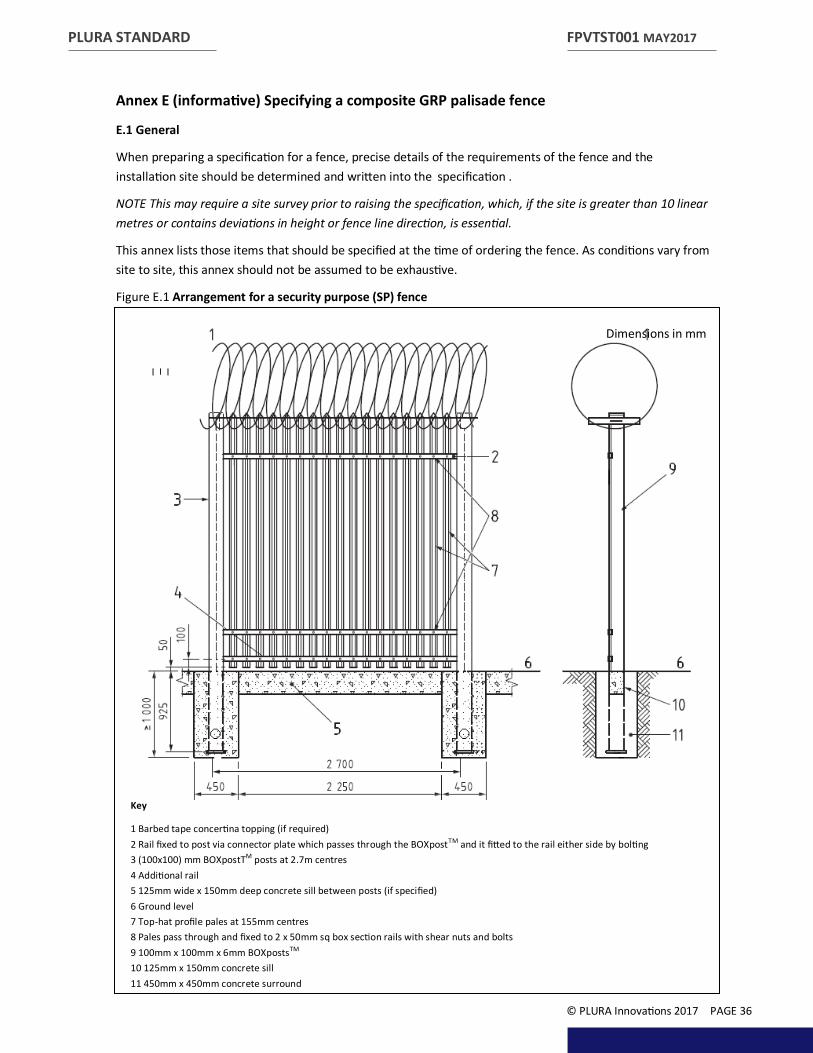
Annex E (informative) Specifying a composite GRP palisade fence
E.1 General
When preparing a specification for a fence, precise details of the requirements of the fence and the installation site should be determined and written into the specification .
NOTE This may require a site survey prior to raising the specification, which, if the site is greater than 10 linear metres or contains deviations in height or fence line direction, is essential.
This annex lists those items that should be specified at the time of ordering the fence. As conditions vary from site to site, this annex should not be assumed to be exhaustive.
Figure E.1 Arrangement for a security purpose (SP) fence
PLURA STANDARD FPVTST001 MAY2017
© PLURA Innovations 2017 PAGE 36
Key
1 Barbed tape concertina topping (if required) 2 Rail fixed to post via connector plate which passes through the BOXpostTM and it fitted to the rail either side by bolting 3 (100x100) mm BOXpostTM posts at 2.7m centres 4 Additional rail 5 125mm wide x 150mm deep concrete sill between posts (if specified) 6 Ground level 7 Top-hat profile pales at 155mm centres 8 Pales pass through and fixed to 2 x 50mm sq box section rails with shear nuts and bolts 9 100mm x 100mm x 6mm BOXpostsTM
10 125mm x 150mm concrete sill 11 450mm x 450mm concrete surround
Dimensions in mm

E.2 Site conditions
The following should be agreed between the client and PLURA at the time of enquiry and/or order:
a) the line and length of fence;
b) the height and type of fence, i.e. GP or SP (see Table 1 and Table 2);
c) the colour of fence;
d) site preparation (see Section 1. 6);
1) site clearance;
2) cutting or filling of ground level;
e) any specific requirements for non-standard post lengths due to ground conditions;
NOTE The requirements for the lengths of posts and stays in British Standard BS 1722-12:2016 and foundation sizes are for average ground conditions. The British Standard and/or this specification document does not cover conditions of particularly firm or soft ground, where other lengths or foundation sizes might be required. Unless otherwise agreed with the installer the client must make separate arrangements for the work required to cut or fill the ground to vary the levels.
e) any special measures required due to site gradients (see Section 1. 9 for solutions to gradients) and;
f) the number and position of any gates (see Section 1. 8).
E.3 Construction of fence
The following items should be specified by the designer / client at the time of enquiry and/or order:
a) pales:
1) whether GP or SP;
2) the shape of tops of pales (see 5.1);
b) posts:
1) 5.3 specifies 2.7 m centres for posts; if shorter bays are required, they should be specified;
2) the design and foundation requirements for removable posts (see 5.3).
c) gates (see also E.2):
1) if any clear openings are required (see NOTE to Table 5);
2) the type of post (see Table 7);
3) locking devices (see 8.4);
4) road profile (see 8.1); and
e) additional security:
1) burrowing (see 6.2);
2) pale removal (see 6.3); and
3) topping (see 6.4).
PLURA STANDARD FPVTST001 MAY2017
© PLURA Innovations 2017 PAGE 37

PLURA STANDARD
Annex F Standard Detail Drawings
F.1 Typical Installation Detail
FPVTST001 MAY2017
© PLURA Innovations 2017 PAGE 38

PLURA STANDARD
F.2 Typical Single Leaf Gate Detail
FPVTST001 MAY2017
© PLURA Innovations 2017 PAGE 39

PLURA STANDARD
F.3 90 Degree Fishtail Assembly Detail
FPVTST001 MAY2017
© PLURA Innovations 2017 PAGE 40

PLURA STANDARD
This page deliberately left blank
FPVTST001 MAY2017
© PLURA Innovations 2017 PAGE 41


