* This product is protected against electrostatic discharge.* Specifications and design are subject to change without
notice.
2 for each pad
Power cord
Vacuum pipe control knob (L)
2
3. WARNINGS, CAUTIONS, AND NOTES
WARNINGWarnings and cautions are placed at critical points in this manual to direct the operator's attention to significant items. They are defined as follows:
WARNING : Failure to comply with a WARNING may result in serious injury or death.
CAUTION : Failure to comply with a CAUTION may result in injury to the operator, or damage to the items involved.
NOTE : A NOTE indicates a procedure or point that is important to the process being described.
EXAMPLE : An EXAMPLE is given to demonstrate a particular procedure point or process.
WARNINGTo avoid damage to the unit, do not turn the power switch OFF until the pump stops automatically by cooling down (until appears on the display) after use.
CAUTIONWhen the power is ON, the temperature of the hot air and the nozzle ranges from 100 to 450°C. (200 to 840°F.). To avoid injury to personnel or damage to items in the work area, observe the following:
● Do not direct the hot air toward personnel or touch the metal parts near the nozzle.● Do not use the product near combustible gases or flammable materials.● Advise those in the work area that the unit can reach very high temperatures and should be considered
potentially dangerous.● Turn the power OFF when no longer using the HAKKO FR-803 or when leaving it unattended.● Before replacing parts or storing the unit, allow the unit to cool and then turn the power OFF.
Observe the following precautions to prevent accidents or damage to the unit.
● Do not strike the handpiece against hard surface or otherwise subject it to physical shock.● Be sure the unit is grounded. Always connect power to a grounded receptacle.● Do not disassemble the pump or the vacuum pump.● Do not modify the unit.● Use only genuine HAKKO replacement parts.● Do not wet the unit or use the unit with wet hands.● Remove power cord by holding the plug – not the wires.● Do not leave the vacuum pump on for long periods of time.● Make sure the work area is well ventilated.● While using the HAKKO FR-803, donʼt do anything which may cause bodily harm or physical damage.
25
HOT
CAUTIO
N
47
9
11
10
3
5
6
8
2
1
13. PARTS LIST / HANDPIECE
Item No. Part No. Part Name Specifications① B3015 Handle With screws② A1523 Heating element 100~120V
A1524 Heating element 220~240V③ B3009 Mica B④ B2995 Quartz glass pipe For support
Handpiece① Pad② Vacuum pipe③ Sensor (internal)④ Hot air button
⑤ Vacuum pipe control knob⑥ Vacuum button
This section displays files 1 to 3 in Auto mode.This section displays a temperature and timer setting time for each step in AUTO mode.
CAUTIONThe displayed and set temperature indicates the temperatures at the sensor.
This meter indicates the airflow rate.This section will be lit during every step in AUTO mode.This knob controls the airflow. The airflow can be set in the range of 5 to 20 l/min.
This button displays and selects the MANUAL and AUTO modes.This indicator lights the selected mode.This indicator lights when the vacuum pump is in operation.Use this button for setting, determining and checking the file number, temperature, timer, etc.This switch turns the power ON and OFF.
The pad absorbs parts.The pad is mounted on the tip of the vacuum pipe.This sensor detects the temperature of the hot air.● MANUAL Mode
When the Start button is pressed, the unit begins blowing hot air. When the Start button is pressed again, the unit begins cooling and stops blowing hot air after reaching 100°C (200°F).
● AUTO ModeWhen the Start button is pressed again, the selected AUTO program begins.
This knob controls the length of the vacuum pipe.This button turns the vacuum pump ON and OFF.
23
UPDOWN
7
3
2
1
13. PARTS LIST / STATION
Pan head screw with spring washerM3 × 6 (4)
Pan head screw with spring, plain washerM3 × 6 (2)
NOTE:Spare or repair parts do not include mounting screws, if they are not listed on the specifications. Screws must be ordered separately.
Pan head screw with spring, plain washerM3 × 6 (2)
5
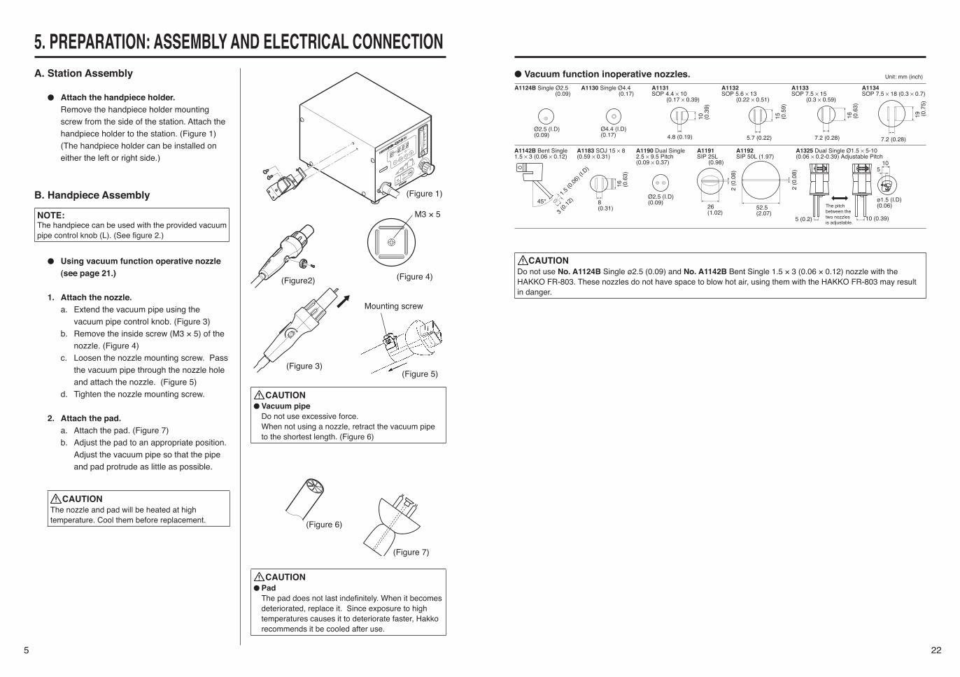
5. PREPARATION: ASSEMBLY AND ELECTRICAL CONNECTIONA. Station Assembly
● Attach the handpiece holder.Remove the handpiece holder mounting screw from the side of the station. Attach the handpiece holder to the station. (Figure 1)(The handpiece holder can be installed on either the left or right side.)
B. Handpiece Assembly
NOTE:The handpiece can be used with the provided vacuum pipe control knob (L). (See figure 2.)
● Using vacuum function operative nozzle (see page 21.)
1. Attach the nozzle.a. Extend the vacuum pipe using the
vacuum pipe control knob. (Figure 3)b. Remove the inside screw (M3 × 5) of the
nozzle. (Figure 4)c. Loosen the nozzle mounting screw. Pass
the vacuum pipe through the nozzle hole and attach the nozzle. (Figure 5)
d. Tighten the nozzle mounting screw.
2. Attach the pad.a. Attach the pad. (Figure 7)b. Adjust the pad to an appropriate position.
Adjust the vacuum pipe so that the pipe and pad protrude as little as possible.
CAUTIONThe nozzle and pad will be heated at high temperature. Cool them before replacement.
CAUTION● Vacuum pipe
Do not use excessive force. When not using a nozzle, retract the vacuum pipe to the shortest length. (Figure 6)
(Figure 1)
M3 × 5
(Figure 4)(Figure2)
(Figure 3)(Figure 5)
(Figure 6)
(Figure 7)
Mounting screw
CAUTION● Pad
The pad does not last indefinitely. When it becomes deteriorated, replace it. Since exposure to high temperatures causes it to deteriorate faster, Hakko recommends it be cooled after use.
22
CAUTIONDo not use No. A1124B Single ø2.5 (0.09) and No. A1142B Bent Single 1.5 × 3 (0.06 × 0.12) nozzle with the HAKKO FR-803. These nozzles do not have space to blow hot air, using them with the HAKKO FR-803 may result in danger.
The size in Name/Specification indicates the size of IC package.
20
10. ERROR MESSAGEWhen the error detection software in the HAKKO FR-803 detects an error, a message is displayed to alert the operator. See “Troubleshooting” for procedures to correct the error.
Sensor Error
Heater Error
This error occurs when there is the possibility of a sensor failure (or a failure in the sensor circuit).
flashes and the power is shut down.
This error occurs when the temperature of the hot air is falling even though the heater is on. The flashes to indicate the possibility of a heater failure.
11. TROUBLESHOOTING WARNING
● Before checking the inside of the HAKKO FR-803 or replacing parts, be sure to disconnect the power plug. Failure to do so may result in electric shock.
● The unit does not operate when the power switch is turned ON.
CHECK : Is the power cord or connection plug discon-nected?
ACTION : Connect it.CHECK : Is the fuse blown?ACTION : Investigate why the fuse blew and then replace the
fuse.
CHECK : Is the sensor broken?ACTION : Measure the resistance value of the sensor.
The normal value is 0 Ω. If the resistance value is abnormal, replace the parts with new parts.
CHECK : Is the heater broken?ACTION : Measure the resistance value of the sensor.
The normal value is 33 Ω (±10%) (100-120V), 85Ω (±10%) (220-240V) at room temperature. If the resistance value is abnormal, replace the parts with new parts.
CHECK : Is the station in Auto mode?ACTION : Put the station into Auto mode.CHECK : Is the value outside the setting range?ACTION : Enter a value that is within the setting range.
CHECK : Is the VACUUM button being pressed?ACTION : Press the VACUUM button.
● flashes, indicating a sensor error.
● flashes, indicating a heater error.
● The profile cannot be set.
● The vacuum pump does not stop when the vacuum button is pressed.
7
6. OPERATIONA. Mode SelectionInsert the control card into the card slot and select your desired mode using the mode selection button. (Figure 10)The HAKKO FR-803 provides the following two modes. The AUTO mode consists of the INSTALL and REMOVE modes.
● Manual ModeIn this mode, air and vacuum pump operation are controlled entirely by manual operation.
NOTE:The timer cannot be set when using MANUAL mode.
● AUTO mode● Install Mode (AUTO) (See page 14.)
This mode is used when installing parts. The vacuum pump will be automatically turned OFF.
● Remove Mode (AUTO) (See page 13.)This mode is used when removing parts. The vacuum pump will be automatically turned ON.
In INSTALL mode, turn ON the vacuum function manually and align the component on the PWB. Vacuum function automatically will turn OFF 5 seconds after starting selected the profile.
In REMOVE mode, the vacuum function automati-cally turns ON during the last 10 seconds of the selected profile. Set the temperature profile shown in the following figure in advance.
(Figure 10)
Step 1 Step 2 Step 3 Cool down
Air t
empe
ratu
re
Timing when the vacuum pump is turned OFF in INSTALL mode
Start
Time
Tempe
ratue
is inc
reasin
g.Temperature is stable.
Temperature is stable.
Temperature
is decreasing.
When the tempera-ture falls to 100°C (200°F), the air stops blowing automati-cally.
Opend timer time
Closed timer time
Tempe
ratue
is inc
reasin
g.
10 seconds
Timing when the vacuum pump is turned ON in REMOVE mode
5 seconds
* In REMOVE mode, turn OFF the vacuum pump manually.
Tempe
ratue
is inc
reasin
g.
Temperature is stable.
8
6. OPERATION
HOT AIR button
VACUUM button
B. Selecting Manual Mode
The temperature/timer is displayed by . The HAKKO FR-803 is preset at 300°C at the factory, see page 9.
● Air Blow1. Start
Press the HOT AIR button on the hand-piece to start the flow of air. The hot air blows from the tip of the nozzle, and the temperature is controlled according to the temperature setting.
2. StopPress the HOT AIR button again. Power to the heater is shut off and cooling begins. When the temperature falls to 100°C. (200°F.), the air stops blowing and the temperature display reads .
● Vacuum FunctionThis function is used to hold the component securely to the pads.1. Start
Press the Vacuum button on the hand-piece. The vacuum pump turns ON and the part is held by suction.
2. StopPress and hold the Vacuum button. The vacuum pump turns OFF.
CAUTIONTo avoid damage to the equipment, do not turn the power switch OFF until appears on the display.
CAUTIONParts held by the pads are very hot. Be careful when removing them from the pads.
To check the set temperature, press the button .
19
9. MAINTENANCE / INSPECTION● Broken Heater or Sensor
① Open the handpiece.
1. Retract the vacuum pipe to its shortest length.
2. Move the tube downward.3. Remove the three screws holding the
handpiece together.4. Remove the pipe from the protruding
portion of the handle.
CAUTIONQuartz glass and heat insulation are inside the pipe. Be careful not to drop or lose these items.
5. Disconnect the heater sensor connector and remove the heater.
CAUTIONDo not apply excessive force to the vacuum pipe.
② Measure the resistance value.
1. Measure the resistance value (a) of the sensor. The normal value is 0Ω.
2. Measure the resistance value (b) of the heater. The normal values are approx-imately 33Ω (±10%) (100-120V), 85Ω (±10%) (220-240V) at room temperature.
If the resistance value is abnormal, replace the part.
(Refer to the instructions included with the replacement part.)
● Replacing the Fuse1. Unplug the power cord from the power recep-
tacle.2. Remove the fuse holder.3. Replace the fuse with new one.4. Put the fuse holder back in place.
�
�
CAUTIONSince there are various hazards with replacing the heating element, be sure to turn off the power and replace them according to the avove procedure.
18
8. OFFSET SETTING METHODNOTE:The temperature at the blowout port varies depends on the nozzle size. The offset temperature can be selected.
CAUTIONChange the mode to MANUAL before setting.The operations cannot be performed in AUTO mode.
Be sure to insert the control card.1. Press the button for 1 second or more.
The mode will be shifted to the offset inputting mode.
2. Input the offset value.The input range is -50 to + 50°C (In °F mode, from -90 to + 90°F)Enter the HUNDREDS digit.a. Use the or buttons to select your
desired value for the HUNDREDS digit. Only 0 (in case of positive) and – (in case of nega-tive) can be input (the same as in °F mode). Select 0 or – and press the button. The TENS digit begins to flash.
Enter the TENS digit.b. Use the or buttons to select your
desired value for the TENS digit. When your desired value is displayed, press the button. The UNITS digit begins to flash.
Enter the UNITS digit.c. Select your desired value for the UNITS digit
in the same manner as for the TENS digit. When your desired value is displayed, press the button. displays and indicates that the temperature setting procedure is completed.
Press the or button
Press the button.
Press and hold the button for more than 1 second.
Press the or button
Press the button.
Press the button.
Press the or button
<In MANUAL mode>Temperature 300°COffset value 0
<In AUTO mode>File 1 File 2 File 3
Mode INSTALL INSTALL INSTALLStep 1 Setting temp.
Timer time200°C
30200°C
30200°C
30Step 2 Setting temp.
Timer time250°C
30250°C
30250°C
30Step 3 Setting temp.
Timer time300°C
30300°C
30300°C
30
● Factory settingCAUTION
Be sure to insert the control card into the card slot before initial resetting.Turn the power switch ON while simultaneously pressing the , and buttons to reset the initial set values upon shipment from the factory. The mode is displayed in MANUAL.Upon shipment from the factory, the data are set to the values as shown in the right tables.
9
6. OPERATIONC.Temperature change method in
MANUAL mode
CAUTIONBe sure to insert the control card into the card slot and set the mode to MANUAL before changing.
Setting change in temperature
CAUTIONThe temperature setting range is 100 to 450°C (200 to 840°F).
Example: Change the temperature setting from 300 to 450°C.
1. Press the button on the temperature setting section for 1 sec. or more.
● The HUNDREDS digit flashes on the display, indicating that the HUNDREDS digit can be entered.
2. Enter the HUNDREDS digit.● Use the or buttons to select your
desired value for the HUNDREDS digit. When your desired value is displayed, press the button. The TENS digit begins to flash.
3. Enter TENS digit.● Use the or buttons to select your
desired value for the TENS digit. When your desired value is displayed, press the
button. The UNITS digit begins to flash.4. Enter the UNITS digit.● Select your desired value for the UNITS
digit in the same manner as for the TENS digit. When your desired value is displayed, press the button. displays and indicates that the temperature setting procedure is completed.
CAUTIONIf the power is turned OFF before the temperature set-ting procedure is completed ( is not displayed), the new setting value will not be stored in memory.
Press the or button.
Press the button once.
Press and hold the but-ton for more than 1 second.
Press the or button.
Press the button once
Press the button once
● Attempting to enter a value outside the setting range will cause the display to begin flashing the HUNDREDS digit again. Reenter a correct value.
● Both the display temperature and the tempera-ture setting are the temperature at the sensor. (Even with the same temperature setting, the temperature of the hot air differs depending on the nozzle size.)
10
D. Setting method in AUTO mode
CAUTIONBe sure to press the button and set the mode to AUTO.
The temperature profiles from 1 to 3 have been initially set. If it is necessary to change, see page 13.
1. Opening up a file
CAUTIONBe sure to insert the control card before opening.
Display a file number using the or button.
NOTE:If the file number is not changed, it is unneces-sary to insert the control card.
2. Pressing the HOT AIR button on the handpiece causes the unit to begin to blow, and setting the temperature profile causes it to start the file program.
3. When all the steps are completed, the unit will be automatically stopped.
Press the or button.
Step 1Temperature display
Temperature display
Temperature display
Timer
Timer
Timer
Step 2
Step 3
Cool down
Temperature is increasing.
Temperature is increasing.
Temperature is increasing.
Temperature is decreasing.
Timer is in operation.
Timer is in operation.
Timer is in operation.
17
7. PARAMETERS
● Parameter change methodParameter change method and buttons.1. °C/°F change
Press the or button, select "C" (Celsius) or "F" (Fahrenheit) and press the
button to enter.2. Change of power save time
Press the or select 30 min, 60 min or ∞ and press the button to enter.
3. Change of timer display unitPress the or button, select “n” (min) or “S” (sec) and press the button to enter.
4. Change of countdown methodPress the or select “o” (Opened timer) or “c” (Closed timer) and press the button to enter. (See the table on page 7.)
5. Change of card-lock functionPress the or button, select 1 or 2 and press the button to enter.The parameter input mode is completed,
is displayed and then returned to the normal mode.
CAUTIONIf the power is turned OFF before the parameter setting procedure is completed ( is not displayed), the new setting value will not be stored in memory.
Parameter Parameter display Initial setting°C/°F change °C or °F C (°C)Power saving time (30 min/60 min/∞) 30, 60 or ∞ 30 (30 min)Timer display unit (min/sec) n or S n (min)Change of count-down method(Opened timer/closed timer)
o or c o (opened timer)
Change of control card lock function(Normal/single lock)
1 or 2 1 (normal)
* In case of simple lock, the change of file number in AUTO mode can be changed without inserting the control card.
CAUTIONBe sure to insert the control card into the card slot before changing.
Press the button.
Press the or button.
Press the or button.
Press the button.
Press the button.
Press the button.
Press the button.● Initial resetting method
CAUTIONBe sure to insert the control card into the card slot before initial resetting.
Turn the power switch ON while simultaneously
pressing the , and buttons to reset to the initial set values upon shipment from the factory. The mode is displayed in MANUAL.
16
Read from the center of the ball.
Turn clockwise to increase the airflow.Turn counterclockwise to decrease the airflow.
9. File writingPress the button for 1 second or more to shift into the file writing mode. Use the or
buttons to display and press the button. The file writing will be completed.
NOTE:If is selected, the data will be returned to the data before change and the mode will be shifted to the file number selection mode.
* In AUTO mode, files are not selected. Select the file to be used and start it.
F. Airflow adjustment
Adjust the flow rate of the hot air while watching the airflow meter. The adjustment range is 5 l/min to 20 l/min.
CAUTIONDo not apply excessive force when turning the airflow control knob.
G. Set data checking method
Setting in Auto modeSelect your desired file No. in advance.
Press the button.
Press and hold the button for more than 1 second.
Mode display
Step 1: Temperature check
Step 1: Time check
Step 2: Temperature check
Step 2: Time check
Use the button to go next.
Use the button to go next.
Use the button to returnto temperature display.
Use the button to returnto temperature display.
Use the button to returnto temperature display.
Use the button to go next.
Use the button to go next.
* If no button is input for 2 seconds or more in any condition, the unit will be returned to normal conditions.
Step 3: Temperature check
Step 3: Time check
Use the and buttonsto change the STEP.
Use the and buttonsto change the STEP.
Use the and buttons to change
the STEP.
.(INSTALL and REMOVE checking)
Press the button.
Press the or button.
11
6. OPERATIOND-1 Setting method in AUTO/INSTALL
mode
● Operations in INSTALL modeThis mode has the following sequence:① Vacuum ON (Manual)② Start/hot air blow (Manual)(Step/start)③ Vacuum OFF after 5 seconds④ Step 1 operation⑤ Step 2 operation⑥ Step 3 operation⑦ Cool down operation
NOTE: The operation can be set from 1 to 3.
● Installation• Advance preparation of P.W.B.Apply an appropriate amount of solder paste to the P.W.B.)① Part suction and positioning
Press the VACUUM button on the handpiece. Have the part sucked by the pads and position the part on the P.W.B. (Figure 1)
② Start (heating)Press the HOT button on the handpiece. Hot air blows from the nozzle to melt the solder. The station operates based on the preprogrammed temperature profile. (Figure 2)
CAUTIONTo stop the program, press the HOT AIR button. Cooling begins.
③ Vacuum stop After 5 seconds, the vacuum turns OFF
and the part is released from suction. (Figure 3)
④ StopWhen the step operation is completed, cooling begins. Make sure the solder has hardened before lifting the handpiece. (Figure 4)
To check the temperature setting, press the button. To change the temperature setting, see “Setting method in AUTO mode” on page 13.
In INSTALL mode, press the HOT AIR button after turning the vacuum function ON manually and aligning the component on the PWB. Vacuum function automatically will turn OFF 5 seconds after starting selected the profile.
②①
④③
Figure 1 Figure 2
Figure 3 Figure 4
Vacuum OFF
12
D-2 Setting method in AUTO/REMOVE
mode
● Operations in REMOVE modeThis mode has the following sequence:① Start/hot air blow (manual)② Step 1 operation③ Step 2 operation④ Step 3 operation⑤ Ten seconds before the last step is
completed, the vacuum automatically turns ON and then a single sound lasting 1 second is generated. Two seconds before completion, a continuous sound is generated.
⑥ Vacuum OFF (manual)⑦ Cool down
NOTE:The operation can be set from 1 to 3.
● Removal• Parts mountingMount the nozzle and pads on the part to be removed. (Figure 1)① Start (heating)
Press the HOT AIR button on the handpiece. Hot air blows from the nozzle and melts the solder. The station operates based on the preprogrammed temperature profile. (Figure 2)
CAUTIONTo stop the program, press the HOT AIR button. Cooling begins.
② Part suction When the timer runs down to 10 sec., the vacuum automatically turns ON and the part is sucked. Lift the handpiece and remove the part from the P.W.B. (Figure 3)
③ Releasing the sucked partTo release the sucked part, press the VACUUM button. (Figure 3)
④ StopAfter that, when the step operation is completed, cooling begins and the airblow stops as soon as the temperature reaches 100°C (200°F). (Figure 4)
To check the set temperature, press the button. To change the set temperature, see “Setting mode in AUTO mode” on page 13.
In REMOVE mode, the vacuum function automatically turns ON during the last 10 seconds of the selected profile.
CAUTIONIf the vacuum button is pressed before the timer runs down to 10 seconds, the vacuum pump turns ON.Press the vacuum button again to stop the air blowing.
②①
④③
Figure 1 Figure 2
Figure 3 Figure 4
15
7. a. The HUNDREDS digit on the temperature/timer display section flashes. Press the
button to select. The TENS digit begins to flash.
b. Enter the TENS digit.Use the or button to select your desired value for the TENS digit. If your desired value is displayed, press the button. The UNITS digit begins to flash.
c. Enter UNITS digit.Use the or button to select your desired value for the UNITS digit. When your desired value is displayed, press the
button. The mode will be shifted to the timer time setting mode in step 3.
8. a. The HUNDREDS digit on the temperature/timer display section flashes. Press the
button to select. The TENS digit begins to flash.
b. Enter the TENS digit.Use the or button to select your desired value for the TENS digit. If your desired value is displayed, press the button. The UNITS digit begins to flash.
c. Enter UNITS digit.Use the or button to select your desired value for the UNITS digit. If your desired value is displayed, press the button. The temperature and timer setting in step 3 will be completed and shifted to the step selection mode.
6. OPERATION
Press the button.
Press the or button.
Press the button.
Press the button.
Press the button.
Press the button.
Press the button.
Press the button.
Press the button.
Press the or button.
Press the button.
14
4. a. The HUNDREDS digit on the temperature/timer display section flashes. Press the
button to select. The TENS digit begins to flash.
b. Enter the TENS digit. Use the or button to select your
desired value for the TENS digit. If your desired value is displayed, press the button. The UNITS digit begins to flash.
c. Enter UNITS digit.Use the or button to select your desired value for the UNITS digit. If your desired value is displayed, press the button. The mode will be shifted to the timer time setting mode in step 1.
5. a. The HUNDREDS digit on the temperature/timer display section flashes. Press the
button to set the HUNDREDS digit to 0. The TENS digit begins to flash.
b. Enter the HUNDREDS digit. Use the or buttons to select your
desired value for the TENS digit. When your desired value is displayed, press the button. The UNITS digit begins to flash.
c. Enter the UNITS digit. Use the or buttons to select your
desired value for the TENS digit. When your desired value is displayed, press the
button. The mode will be shifted into the step selection mode.
6. Use the or buttons to select your desired step. Since it is not changed in step 2, select step 3. When your desired value is displayed, press the button to select. The mode will be shifted to the temperature setting mode.
Press the button.
Press the or button.
Press the button.
Press the button.
Press the button.
Press the or button.
Press the button.
Press the or button.
Press the button.
Press the or button.
Press the or button.
Press the button.
13
E. File changing method in AUTO mode
CAUTIONBe sure to insert the control card into the card slot before changing.
File initial settingFile 1 File 2 File 3
Mode INSTALL INSTALL INSTALLStep 1 Setting temperature 200 200 200
timer time 30 30 30Step 2 Setting temperature 250 250 250
timer time 30 30 30Step 3 Setting temperature 300 300 300
timer time 30 30 30
Example: When file 2 is changed as follows:File 2
Mode REMOVEStep 1 Setting temperature 250
timer time 25Step 2 Setting temperature 250
timer time 30Step 3 Setting temperature 320
timer time 25
1. If the button is pressed for 1 second or more, the file number display section flashes. Select the file number using the or button. If your desired file number is displayed, press the button. The mode will be shifted to the INSTALL or REMOVE selection mode.
2. Use the or button to display . Then, press the button to select and shift to the step selection mode.
3. Select your desired step using the or button. Display your desired step and press the button to select. After that, the mode will be shifted to temperature setting mode in step 1.
6. OPERATION
Press the or button.
Press the button.
Press and hold the button for more than 1 second.
NOTE:The temperature setting range: 100°C - 450°C (200°F - 840°F).The time setting range: 0 sec. - 300 sec. (0 min. - 5 min.)
● Attempt to enter a value outside the setting range will cause the display to begin flashing the HUNDREDS digit again. Reenter a correct value.
● Both the display temperature and the temperature setting are the temperature at the sensor. (Even with the same temperature setting, the temperature of the hot air differs depending on the nozzle size.)
● If the time setting is set to 0 sec., the step can be cancelled.