FR-S520E-0.1K to 3.7K (-C)FR-S540E-0.4K to 3.7KFR-S520SE-0.1K to 1.5KFR-S510WE-0.1K to 0.75K
IB(NA)-0600152E-C (0706) MEE Printed in Japan Specifications subject to change without notice.
A-1
1. Electric Shock Prevention
Thank you for choosing this Mitsubishi Transistorized inverter.This instruction manual (detailed) provides instructions for advanced use of the FR-S500 series inverters.Incorrect handling might cause an unexpected fault. Before using the inverter, alwaysread this instruction manual and the instruction manual (basic) [IB-0600151E] packedwith the product carefully to use the equipment to its optimum.
This section is specifically about safety mattersDo not attempt to install, operate, maintain or inspect the inverter until you have readthrough this instruction manual (basic) and appended documents carefully and canuse the equipment correctly. Do not use the inverter until you have a full knowledgeof the equipment, safety information and instructions.In this instruction manual (detailed), the safety instruction levels are classified into"WARNING" and "CAUTION".
Assumes that incorrect handling may cause hazardousconditions, resulting in death or severe injury.Assumes that incorrect handling may cause hazardousconditions, resulting in medium or slight injury, or may causephysical damage only.
Note that even the level may lead to a serious consequenceaccording to conditions. Please follow the instructions of both levels because they areimportant to personnel safety.
WARNINGWhile power is on or when the inverter is running, do not open the front cover. Youmay get an electric shock.Do not run the inverter with the front cover or wiring cover removed. Otherwise,you may access the exposed high-voltage terminals or the charging part of thecircuitry and get an electric shock. Also, the inverter's ability to withstandearthquakes will deteriorate.Even if power is off, do not remove the front cover except for wiring or periodicinspection. You may access the charged inverter circuits and get an electric shock.Before starting wiring or inspection, check to make sure that the 3-digit LED invertermonitor is off, wait for at least 10 minutes after the power supply has been switchedoff, and check to make sure that there are no residual voltage using a tester or thelike. This inverter must be earthed (grounded). Earthing (grounding) must conform tothe requirements of national and local safety regulations and electrical codes.(NEC section 250, IEC 536 class 1 and other applicable standards)Any person who is involved in the wiring or inspection of this equipment should befully competent to do the work.Always install the inverter before wiring. Otherwise, you may get an electric shockor be injured.Perform setting dial and key operations with dry hands to prevent an electricshock.Do not subject the cables to scratches, excessive stress, heavy loads or pinching.Otherwise, you may get an electric shock.Do not change the cooling fan while power is on. It is dangerous to change thecooling fan while power is on.When you have removed the front cover, do not touch the connector above the 3-digit monitor LED display. Otherwise, you get an electrick shock.
WARNING
CAUTION
CAUTION
A-2
2. Fire Prevention
3. Injury Prevention
4. Additional InstructionsAlso note the following points to prevent an accidental failure, injury, electric shock,etc.
(1) Transportation and installation
CAUTIONInstall the inverter and brake resistor on an incombustible wall without holes, etc.Installing the inverter and brake resistor directly on or near a combustible surface couldlead to a fire.If the inverter has become faulty, switch off the inverter power. A continuous flow oflarge current could cause a fire.When using a brake resistor, make up a sequence that will turn off power when analarm signal is output. Otherwise, the brake resistor may excessively overheat dueto damage of the brake transistor and such, causing a fire.Do not connect the resistor directly to the DC terminals P and N. This could cause a fire.
CAUTIONApply only the voltage specified in the instruction manual to each terminal toprevent damage, etc.Always connect to the correct terminal to prevent damage, etc.Always make sure that polarity is correct to prevent damage, etc.While power is on or for some time after power-off, do not touch the inverter as it ishot and you may get burnt.
CAUTIONWhen carrying products, use correct lifting gear to prevent injury.Do not stack the inverter boxes higher than the number recommended.Ensure that installation position and material can withstand the weight of theinverter. Install according to the information in the instruction manual.Do not install or operate if the inverter is damaged or has parts missing.When carrying the inverter, do not hold it by the front cover or setting dial; it mayfall off or fail.Do not stand or rest heavy objects on the inverter.Check the inverter mounting orientation is correct.Prevent other conductive bodies as screws and metal fragments or otherflammable substance as oil from entering the inverter.As the inverter is a precision instrument, do not drop or subject it to impact.Use the inverter under the following environmental conditions: This could causethe inverter damage.
*Temperatures applicable for a short time, e.g. in transit.
Env
ironm
ent
Ambient Temperature
-10°C to +50°C (non-freezing)(-10°C to +40°C for totally enclosed structure feature)
Ambient humidity 90%RH maximum (non-condensing)Storagetemperature -20°C to +65°C *
Atmosphere Indoors (free from corrosive gas, flammable gas, oil mist,dust and dirt)
Altitude/vibration Max.1000m above sea level 5.9m/s2 or less
A-3
(2) Wiring
(3) Trial run
(4) Operation
CAUTIONDo not fit capacitive equipment such as power factor correction capacitor,capacitor type filter (option FR-BIF(-H)) or surge suppressor to the output of theinverter.The connection orientation of the output cables U, V, W to the motor will affect thedirection of rotation of the motor.
CAUTIONCheck all parameters, and ensure that the machine will not be damaged by asudden start-up.When the load GD2 is small (at the motor GD or smaller) for 400V from 1.5K to 3.7K, theoutput current may vary when the output frequency is in the 20Hz to 30Hz range.If this is a problem, set the Pr.72 "PWM frequency selection" to 6kHz or higher.(When setting the PWM to a higher frequency, check for noise or leakage currentproblem and take countermeasures against it.)
WARNINGWhen you have chosen the retry function, stay away from the equipment as it willrestart suddenly after an alarm stop.Since the [STOP] key is valid only when functions are set (refer to page 115),provide a circuit and switch separately to make an emergency stop (power off,mechanical brake operation for emergency stop, etc).Make sure that the start signal is off before resetting the inverter alarm. A failure todo so may restart the motor suddenly.The load used should be a three-phase induction motor only. Connection of anyother electrical equipment to the inverter output may damage the equipment.Do not modify the equipment.Do not perform parts removal which is not instructed in this manual. Doing so maylead to fault or damage of the inverter.
A-4
(5) Emergency stop
(6) Maintenance, inspection and parts replacement
(7) Disposing of the inverter
(8) General instructions
CAUTIONThe electronic thermal relay function does not guarantee protection of the motorfrom overheating.Do not use a magnetic contactor on the inverter input for frequent starting/stoppingof the inverter.Use a noise filter to reduce the effect of electromagnetic interference. Otherwisenearby electronic equipment may be affected.Take measures to suppress harmonics. Otherwise power supply harmonics fromthe inverter may heat/damage the power capacitor and generator.When a 400V class motor is inverter-driven, please use an insulation-enhancedmotor or measures taken to suppress surge voltages. Surge voltages attributable tothe wiring constants may occur at the motor terminals, deteriorating the insulation ofthe motor.When parameter clear or all clear is performed, reset the required parametersbefore starting operations. Each parameter returns to the factory setting.The inverter can be easily set for high-speed operation. Before changing itssetting, fully examine the performances of the motor and machine.In addition to the inverter's holding function, install a holding device to ensure safety.Before running an inverter which had been stored for a long period, alwaysperform inspection and test operation.
CAUTIONProvide a safety backup such as an emergency brake which will prevent themachine and equipment from hazardous conditions if the inverter fails.When the breaker on the inverter primary side trips, check for the wiring fault (shortcircuit), damage to internal parts of the inverter, etc. Identify the cause of the trip,then remove the cause and power on the breaker. When any protective function is activated, take the appropriate corrective action,then reset the inverter, and resume operation.
CAUTIONDo not carry out a megger (insulation resistance) test on the control circuit of theinverter.
CAUTIONTreat as industrial waste.
Many of the diagrams and drawings in this instruction manual (detailed) show the inverterwithout a cover, or partially open. Never operate the inverter in this manner. Always replacethe cover and follow this instruction manual (detailed) when operating the inverter.
CO
NTE
NTS
I
CONTENTS
1. WIRING 1
1.1 Standard connection diagram and terminal specifications ..21.1.1 Standard connection diagram ....................................................................... 21.1.2 Explanation of main circuit terminals............................................................. 3
1.2 Main circuit terminals ...............................................................61.2.1 Terminal block layout .................................................................................... 61.2.2 Cables, wiring length, and crimping terminals............................................... 81.2.3 Wiring instructions ......................................................................................... 91.2.4 Selection of peripheral devices ................................................................... 101.2.5 Leakage current and installation of earth (ground) leakage circuit breaker 121.2.6 Power-off and magnetic contactor (MC)...................................................... 161.2.7 Regarding the installation of the reactor...................................................... 171.2.8 Regarding noise and the installation of a noise filter................................... 181.2.9 Earthing (Grounding) precautions ............................................................... 191.2.10 Power supply harmonics ............................................................................. 201.2.11 Harmonic suppression guideline ................................................................. 211.2.12 Inverter-driven 400V class motor ................................................................ 25
1.3 How to use the control circuit terminals...............................261.3.1 Terminal block layout .................................................................................. 261.3.2 Wiring instructions ....................................................................................... 261.3.3 Changing the control logic........................................................................... 27
1.4 Input terminals.........................................................................291.4.1 Run (start) and stop (STF, STR, STOP) ..................................................... 291.4.2 Connection of frequency setting potentiometer and
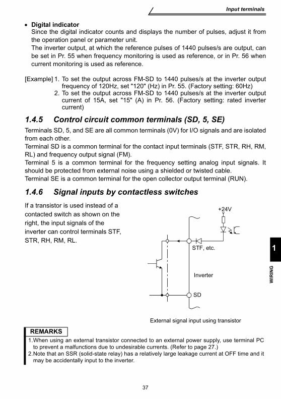
output frequency meter (10, 2, 5, 4, AU) ..................................................... 321.4.3 External frequency selection (REX, RH, RM, RL) ....................................... 331.4.4 Indicator connection and adjustment (FM) .................................................. 351.4.5 Control circuit common terminals (SD, 5, SE)............................................. 371.4.6 Signal inputs by contactless switches ......................................................... 37
1.5 How to use the input signals (assigned terminals RL, RM, RH, STR)..................................38
1.5.1 Multi-speed setting (RL, RM, RH, REX signals): Pr. 60 to Pr. 63 setting "0, 1, 2, 8" Remote setting (RL, RM, RH signals): Pr. 60 to Pr. 63 setting "0, 1, 2" ................................................................... 38
1.5.2 Second function selection (RT signal): Pr. 60 to Pr. 63 setting "3" ............. 38
II
1.5.3 Current input selection "AU signal": Pr. 60 to Pr. 63 setting "4".................. 381.5.4 Start self-holding selection (STOP signal): Pr. 60 to Pr. 63 setting "5" ....... 391.5.5 Output shut-off (MRS signal): Pr. 60 to Pr. 63 setting "6" ........................... 391.5.6 External thermal relay input: Pr. 60 to Pr. 63 setting "7" ............................. 401.5.7 Jog operation (JOG signal): Pr. 60 to Pr. 63 setting "9".............................. 401.5.8 Reset signal: Pr. 60 to Pr. 63 setting "10"................................................... 411.5.9 PID control valid terminal: Pr. 60 to Pr. 63 setting "14"............................... 421.5.10 PU operation/external operation switchover: Pr. 60 to Pr. 63 setting "16" .. 42
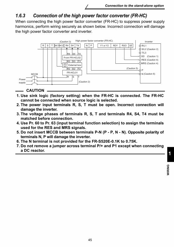
1.6 Connection to the stand-alone option ..................................431.6.1 Connection of the dedicated external brake resistor (option) (FR-S520E-0.4K
to 3.7K only)................................................................................................ 431.6.2 Connection of the brake unit (BU type)....................................................... 441.6.3 Connection of the high power factor converter (FR-HC)............................. 451.6.4 Connection of the power regeneration common converter (FR-CV)........... 46
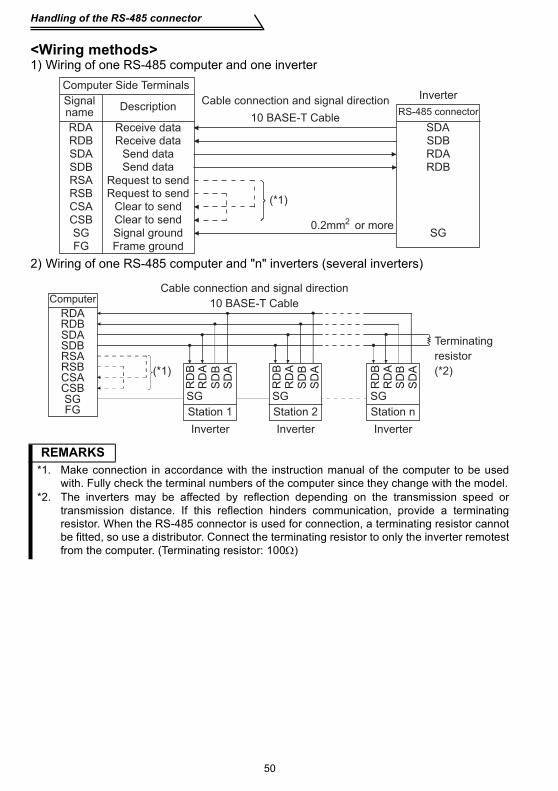
1.7 Handling of the RS-485 connector ........................................ 471.7.1 Connection of the parameter unit (FR-PU04) ............................................. 471.7.2 Wiring of RS-485 communication ............................................................... 48
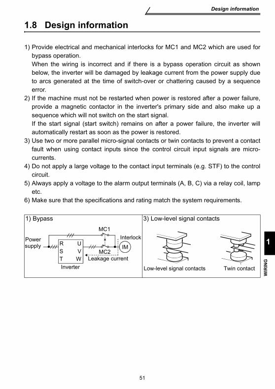
1.8 Design information .................................................................51
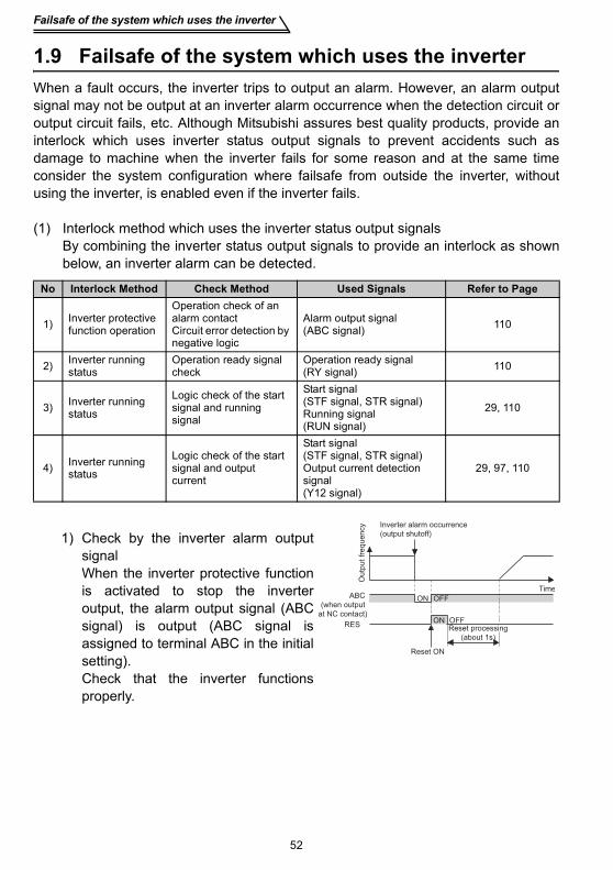
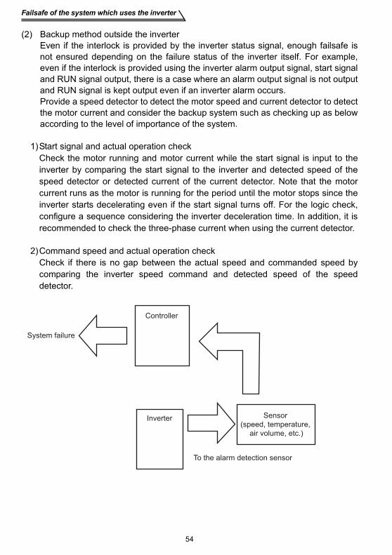
1.9 Failsafe of the system which uses the inverter.................... 52
2. FUNCTIONS 55
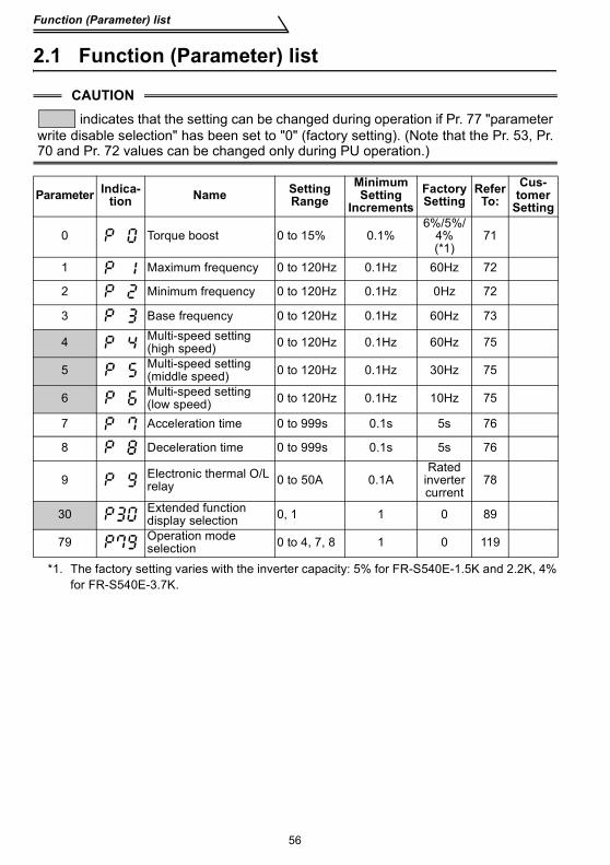
2.1 Function (Parameter) list........................................................56
2.2 List of parameters classified by purpose of use..................69
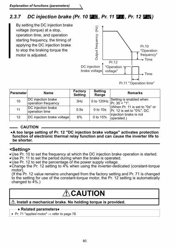
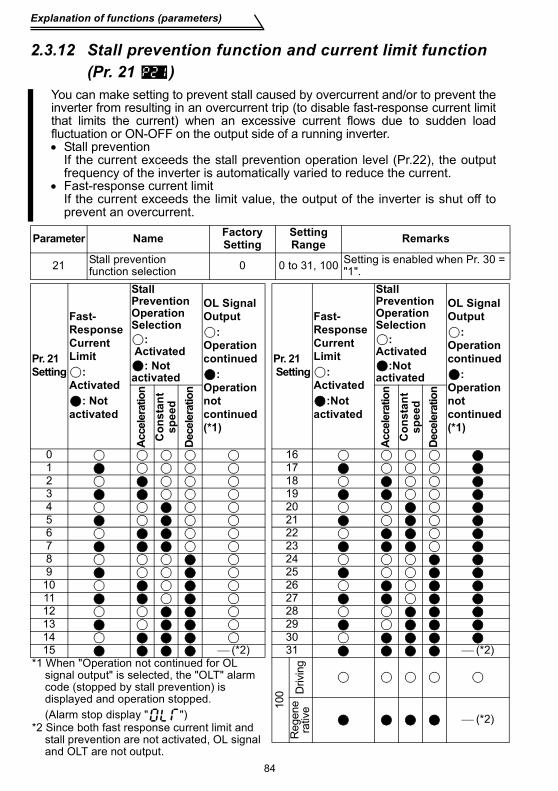
2.3 Explanation of functions (parameters) ................................. 712.3.1 Torque boost (Pr. 0 , Pr. 46 ) ...................................................................... 712.3.2 Maximum and minimum frequency (Pr. 1 , Pr. 2 ) ...................................... 722.3.3 Base frequency, base frequency voltage (Pr.3 , Pr.19 , Pr.47 ).................. 732.3.4 Multi-speed operation (Pr. 4, Pr. 5, Pr. 6, Pr. 24 to Pr. 27, Pr. 80 to Pr. 87)752.3.5 Acceleration/deceleration time (Pr. 7 , Pr. 8 , Pr. 20 , Pr. 44 , Pr. 45 ) ....... 762.3.6 Selection and protection of a motor (Pr. 9 , Pr. 71 , H7 ) ............................ 782.3.7 DC injection brake (Pr. 10 , Pr. 11 , Pr. 12 ) ............................................... 802.3.8 Starting frequency (Pr. 13 )......................................................................... 812.3.9 Load pattern selection (Pr. 14 )................................................................... 822.3.10 Jog operation (Pr.15 , Pr.16 )...................................................................... 832.3.11 RUN key rotation direction selection (Pr.17 ).............................................. 832.3.12 Stall prevention function and current limit function (Pr. 21 ) ....................... 842.3.13 Stall prevention (Pr. 22 , Pr. 23 , Pr. 28 ) .................................................... 86
CO
NTE
NTS
III
2.3.14 Acceleration/deceleration pattern (Pr. 29 ).................................................. 882.3.15 Extended function display selection (Pr. 30 ) .............................................. 892.3.16 Frequency jump (Pr. 31 to Pr. 36 ) ............................................................. 892.3.17 Speed display (Pr. 37 )................................................................................ 902.3.18 Biases and gains of the frequency setting voltage (current)
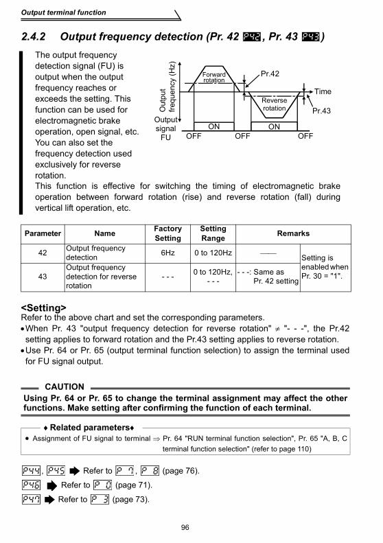
2.4 Output terminal function ........................................................952.4.1 Up-to-frequency sensitivity (Pr. 41 ) ............................................................ 952.4.2 Output frequency detection (Pr. 42 , Pr. 43 )............................................... 96
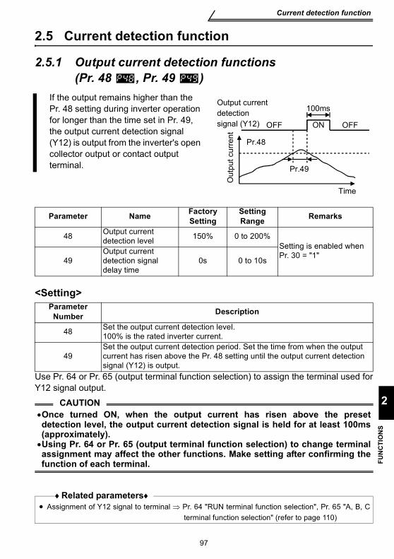
2.5 Current detection function .....................................................972.5.1 Output current detection functions (Pr. 48 , Pr. 49 ).................................... 972.5.2 Zero current detection (Pr. 50 , Pr. 51 )....................................................... 98
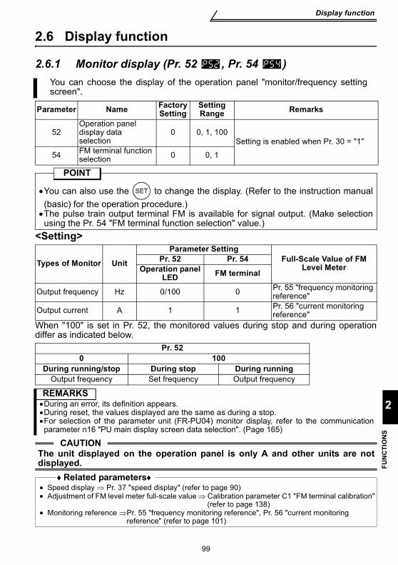
2.6 Display function ......................................................................992.6.1 Monitor display (Pr. 52 , Pr. 54 ).................................................................. 992.6.2 Setting dial function selection (Pr. 53 )...................................................... 1002.6.3 Monitoring reference (Pr. 55 , Pr. 56 )....................................................... 101
2.7 Restart operation function ...................................................1012.7.1 Restart setting (Pr. 57 , Pr. 58 , H6 ) ......................................................... 101
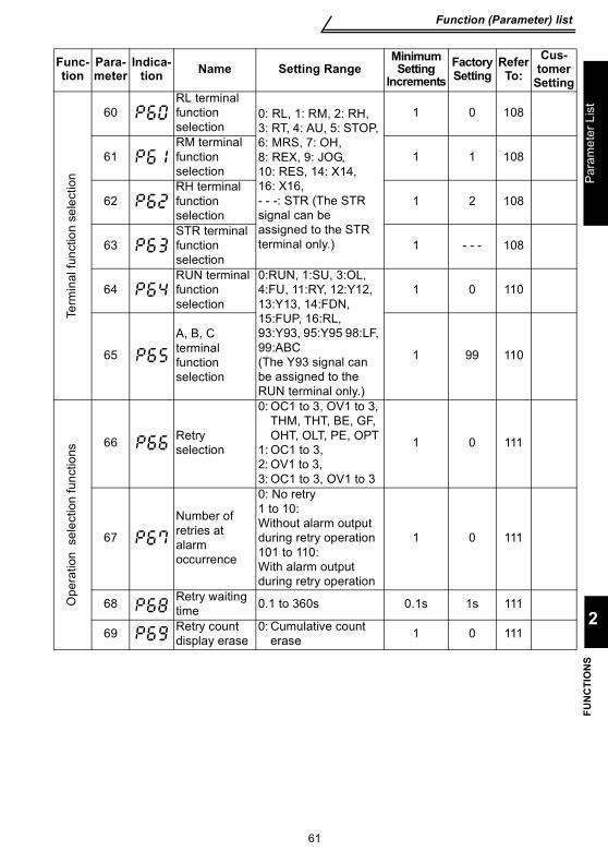
2.9 Terminal function selection..................................................1082.9.1 Input terminal function selection (Pr. 60 , Pr. 61 , Pr. 62 , Pr. 63 ) ............ 1082.9.2 Output terminal function selection (Pr. 64 , Pr. 65 ) .................................. 110
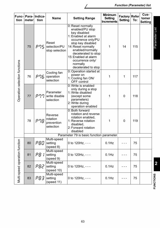
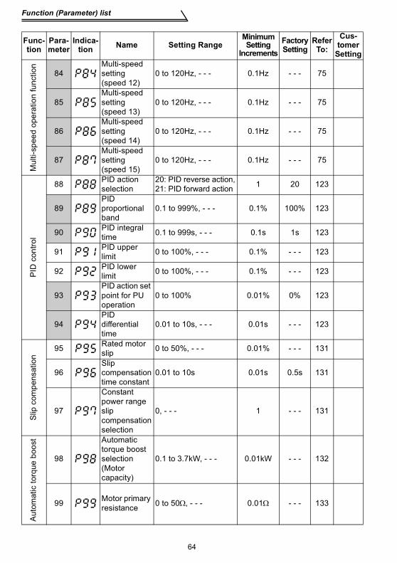
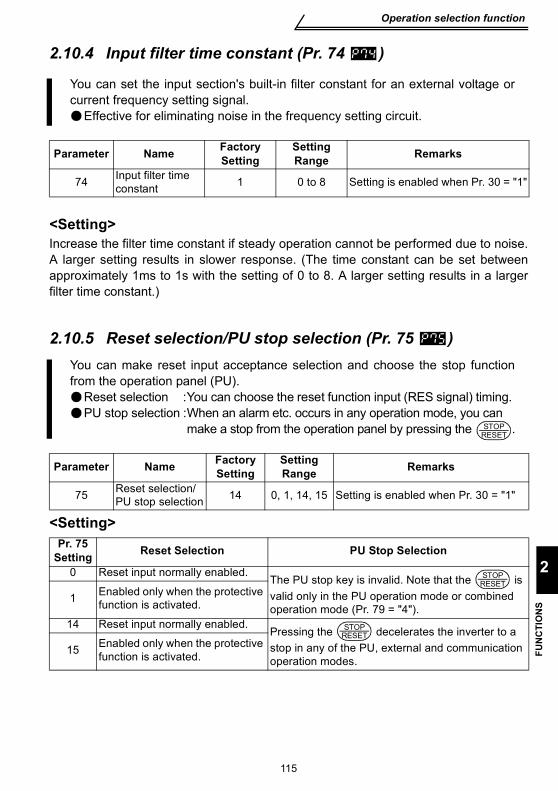
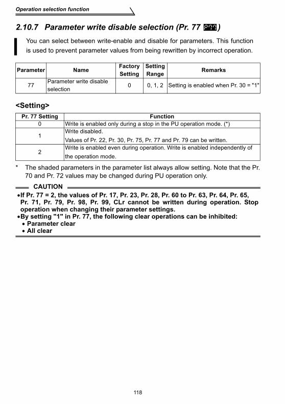
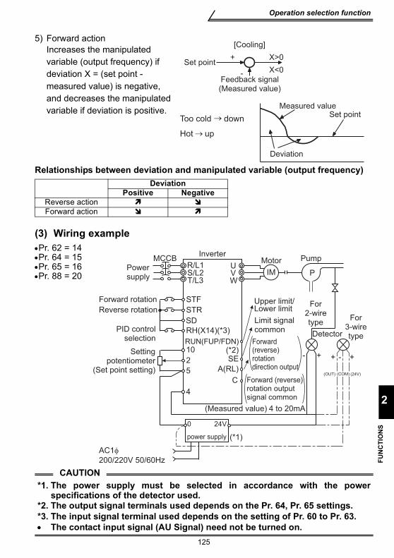
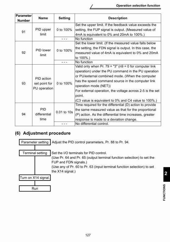
2.10 Operation selection function................................................1112.10.1 Retry function (Pr. 66 , Pr. 67 , Pr. 68 , Pr. 69 ) ........................................ 1112.10.2 PWM carrier frequency and long wiring mode (Pr. 70 , Pr. 72 )................ 1132.10.3 Voltage input selection (Pr. 73 ) ................................................................ 1142.10.4 Input filter time constant (Pr. 74 ) .............................................................. 1152.10.5 Reset selection/PU stop selection (Pr. 75 )............................................... 1152.10.6 Cooling fan operation selection (Pr. 76 ) ................................................... 1172.10.7 Parameter write disable selection (Pr. 77 ) ............................................... 1182.10.8 Reverse rotation prevention selection (Pr. 78 ) ......................................... 1192.10.9 Operation mode selection (Pr. 79 ) ........................................................... 1192.10.10PID control (Pr. 88 to Pr. 94 ) ................................................................... 123
2.11 Auxiliary function ..................................................................1312.11.1 Slip compensation (Pr. 95 , Pr. 96 , Pr. 97 ).............................................. 131
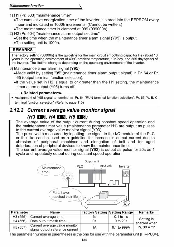
2.12 Maintenance function ........................................................... 1332.12.1 Maintenance output function (H1, H2 ) ..................................................... 1332.12.2 Current average value monitor signal (H3, H4, H5)................... 134
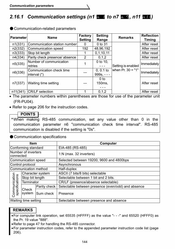
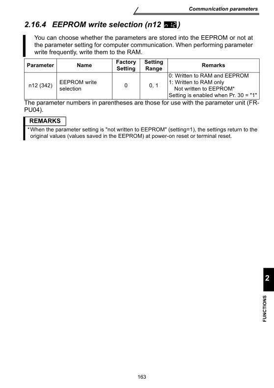
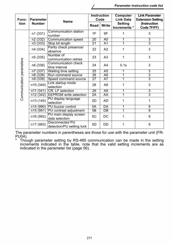
2.16 Communication parameters................................................. 1422.16.1 Communication settings (n1 to n7 , n11 ) ................................................ 1442.16.2 Operation and speed command source (n8 , n9 ) .................................... 1602.16.3 Link startup mode selection (n10 )............................................................ 1612.16.4 EEPROM write selection (n12 ) ................................................................ 163
2.17 Parameter unit (FR-PU04) setting........................................ 1642.17.1 PU display language selection (n13 ) ....................................................... 1642.17.2 PU buzzer control (n14 ) ........................................................................... 1642.17.3 PU contrast adjustment (n15 ) .................................................................. 1652.17.4 PU main display screen data selection (n16 )........................................... 1652.17.5 Disconnected PU detection/PU setting lock selection (n17 ) .................... 166
3. PROTECTIVE FUNCTIONS 169
3.1 Errors (Alarms)...................................................................... 1703.1.1 Error (alarm) definitions ............................................................................ 1713.1.2 To know the operating status at the occurrence of alarm
(only when FR-PU04 is used) ................................................................... 1793.1.3 Correspondence between digital and actual characters ........................... 1793.1.4 Resetting the inverter................................................................................ 1793.1.5 Checking of the alarm history ................................................................... 180
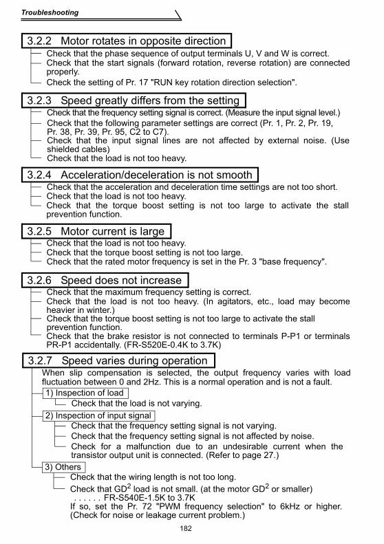
3.2 Troubleshooting.................................................................... 1813.2.1 Motor remains stopped ............................................................................. 1813.2.2 Motor rotates in opposite direction............................................................ 1823.2.3 Speed greatly differs from the setting ....................................................... 182
CO
NTE
NTS
V
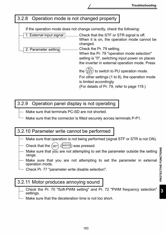
3.2.4 Acceleration/deceleration is not smooth.................................................... 1823.2.5 Motor current is large ................................................................................ 1823.2.6 Speed does not increase........................................................................... 1823.2.7 Speed varies during operation .................................................................. 1823.2.8 Operation mode is not changed properly .................................................. 1833.2.9 Operation panel display is not operating ................................................... 1833.2.10 Parameter write cannot be performed....................................................... 1833.2.11 Motor produces annoying sound............................................................... 183
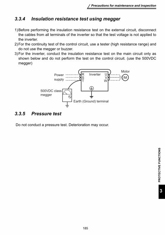
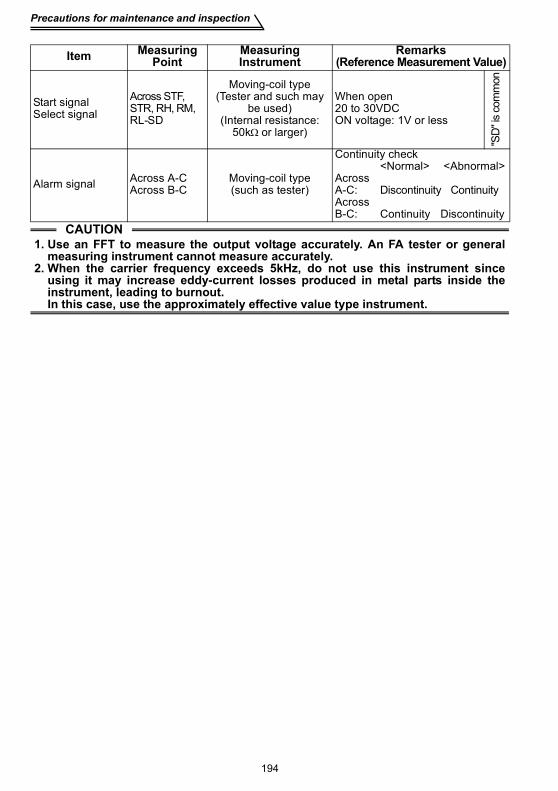
3.3 Precautions for maintenance and inspection.....................1843.3.1 Precautions for maintenance and inspection ............................................ 1843.3.2 Inspection item .......................................................................................... 1843.3.3 Periodic inspection .................................................................................... 1843.3.4 Insulation resistance test using megger .................................................... 1853.3.5 Pressure test ............................................................................................. 1853.3.6 Daily and periodic inspection..................................................................... 1863.3.7 Checking the inverter and converter module............................................. 1883.3.8 Replacement of parts ................................................................................ 1893.3.9 Measurement of main circuit voltages, currents and powers .................... 192
4. SPECIFICATIONS 195
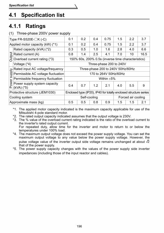
4.1 Specification list ....................................................................1964.1.1 Ratings ...................................................................................................... 1964.1.2 Common specifications ............................................................................. 200
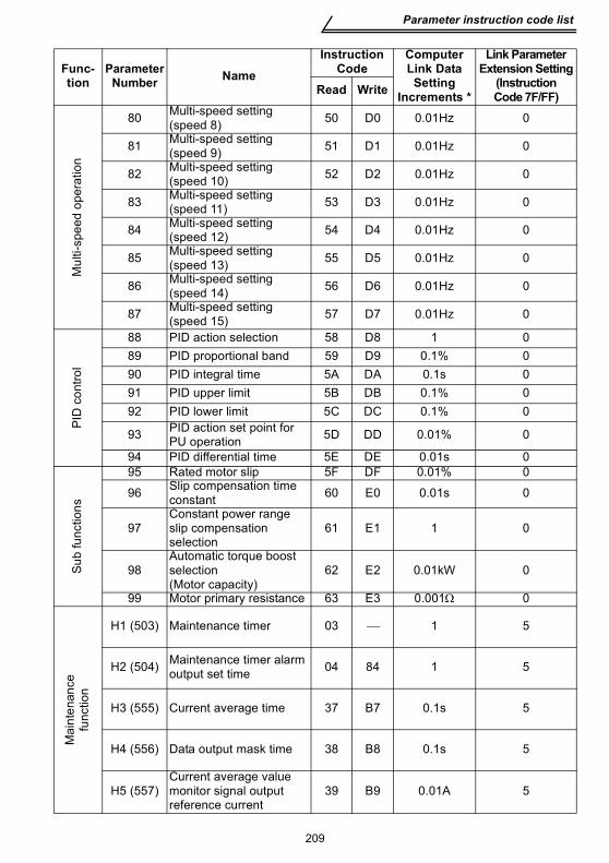
APPENDIX 1 Parameter instruction code list ...............................206
1. WIRING
Chapter 2
Chapter 3
Chapter 4
Chapter 1
1
This chapter explains the basic "wiring" for use of this product. Alwaysread the instructions before use.For description of "installation", refer to the instruction manual (basic).
1.1 Standard connection diagram and terminal specifications ..................................................... 2
1.2 Main circuit terminals ........................................ 61.3 How to use the control circuit terminals.......... 261.4 Input terminals.................................................... 291.5 How to use the input signals (assigned
terminals RL, RM, RH, STR) .............................. 381.6 Connection to the stand-alone option.............. 431.7 Handling of the RS-485 connector...................... 471.8 Design information............................................. 51
<Abbreviations>•PUOperation panel and parameter unit (FR-PU04)
•InverterMitsubishi transistorized inverter FR-S500 series
•FR-S500Mitsubishi transistorized inverter FR-S500 series
•Pr.Parameter number
Standard connection diagram and terminal specifications
2
1.1 Standard connection diagram and terminal specifications
1.1.1 Standard connection diagramThree-phase 200V power inputThree-phase 400V power input
REMARKS*1. The N/- terminal is not provided for the FR-S520E-0.1K to 0.75K.*2. The PR terminal is provided for the FR-S520E-0.4K to 3.7K.*3. Not needed when the setting dial is used for calibration.
Used when calibration must be made near the frequency meter for such a reason as a remote frequency meter.However, the frequency meter needle may not deflect to full-scale if the calibration resistor is connected.In this case, use this resistor and setting dial together.
*4. You can switch the position of sink and source logic. (Refer to page 27.)*5. When the setting potentiometer is used frequently, use a 2W1kΩ potentiometer.*6. The terminal functions change with input terminal function selection (Pr. 60 to Pr. 63). (Refer to page 108.)
(RES, RL, RM, RH, RT, AU, STOP, MRS, OH, REX, JOG, X14, X16, (STR) signal selection)*7. The terminal function changes according to the setting of output terminal function selection (Pr. 64, Pr. 65).
(Refer to page 110.) (RUN, SU, OL, FU, RY, Y12, Y13, FDN, FUP, RL, Y93, Y95, LF, ABC signal selection)
InverterMotor
IMUVW
RUN
SE
Running
Alarm output
Operation status
output
Open collector
Open collector outputs
A
B
C
Frequency setting potentiometer
1/2W1kW
Frequency setting signals (Analog)
10
22
3
1
4 to 20mADC(+) 4
0 to 5VDC0 to 10VDC
5Current input(-)
(+5V)
(Common)
(4 to 20mADC)
Selected
output common
Low speed RL
MCCB MC
DC reactor(FR-HEL/BEL: Option)
Jumper: Remove this jumper when DC reactoris connected.
P1
SINK
SOURCE
Multi-speed
selection
Take care not to short terminals PC-SD.
RS-485 Connector
Three-phase AC power supply
Control circuit terminalMain circuit terminal
When using the current input as the frequency setting signal, set "4" in any of Pr. 60 to Pr. 63 (inputterminal function selection), assign AU (current input selection) to anyof terminals RH, RM, RL and STR and turn on the AU signal.
Control input
signals
(No voltage
input allowed)
STF
STR
RM
Forward rotation start
Reverse rotation start
Middle speed
High speed RH
*3
FM
SD
(+)Calibration resistor
(-)
Earth (Ground)
R Brake resister
Earth
(Ground)External transistor common24VDC power supplyContact input common (source)
SD
PC
Contact input common
Indicator1mA full-scale Analog meter(Digital indicator)
*6
*4
*6
*6
*6
*7
*7
*7
*7
*1
*2
*5
PR
R/L1S/L2T/L3
P/+
N/-
Standard connection diagram and terminal specifications
WIR
ING
3
1
Single-phase 200V power inputSingle-phase 100V power input
1.1.2 Explanation of main circuit terminals(1) Main circuit
CAUTIONTo prevent a malfunction due to noise, keep the signal cables more than 10cm awayfrom the power cables.
REMARKS•To ensure safety, connect the power input to the inverter via a magnetic contactor and earth leakage
circuit breaker or moulded case circuit breaker, and use the magnetic contactor to switch power on-off.•The output is three-phase 200V.
Terminal Symbol Terminal Name Description
R/L1, S/L2, T/L3 (*1) AC power input Connect to the commercial power supply.
U, V, W Inverter output Connect a three-phase squirrel-cage motor.
P/+, PR (*2) Brake resistor connection
Connect the optional brake resistor (MRS/MYS type, FR-ABR) (The brake resistor can be connected to the FR-S520E-0.4K to 3.7K only.)
P/+, N/− Brake unit connection
Connect the brake unit (BU), power regeneration common converter (FR-CV) or high power factor converter (FR-HC). (The N/- terminal is not provided for the FR-S520E-0.1K to 0.75K.)
P/+, P1 DC reactor connection
Remove the jumper across terminals P - P1 and connect the optional DC reactor (FR-HEL(-H)/FR-BEL(-H)).(The single-phase 100V power input model cannot be connected.)
Earth (ground) For earthing (grounding) the inverter chassis. Must be earthed (grounded).
*1. When using single-phase power input, terminals are R/L1 and S/L2.*2. The PR terminal is provided for the FR-S520E-0.4K to 3.7K.
MCCB
IMUVW
MCPower
supply
Motor
Earth (Ground)
S/L2
R/L1
Standard connection diagram and terminal specifications
4
(2) Control circuitSymbol Terminal Name Definition
Inpu
t sig
nals
Con
tact
inpu
t
STF Forward rotation start
Turn on the STF signal to start forward rotation and turn it off to stop.
When the STF and STR signals are turned on simultaneously, the stop command is given.
STR Reverse rotation start
Turn on the STR signal to start reverse rotation and turn it off to stop. The terminal
functions change with input terminal function selection (Pr. 60 to Pr. 63).(*3)
RHRMRL
Multi-speed selection
Turn on the RH, RM and RL signals in appropriate combinations to select multiple speeds.The priorities of the speed commands are in order of jog, multi-speed setting (RH, RM, RL, REX) and AU.
SD(*1, 6)
Contact input common (sink)(initial setting)
Common terminal for contact input terminal (sink logic) and terminal FM.
External transistor common (source)
When connecting the transistor output (open collector output), such as a programmable controller (PLC), when source logic is selected, connect the external power supply common for transistor output to this terminal to prevent a malfunction caused by undesirable currents.
24VDC power supply common
Common output terminal for 24VDC 0.1A power supply (PC terminal)Isolated from terminals 5 and SE.
PC(*1)
External transistor common (sink) (initial setting)
When connecting the transistor output (open collector output), such as a programmable controller (PLC), when sink logic is selected, connect the external power supply common for transistor output to this terminal to prevent a malfunction caused by undesirable currents.
Contact input common (source) Common terminal for contact input terminal (source logic)
24VDC power supply Can be used as 24VDC 0.1A power supply.
10 Frequency setting power supply 5VDC, Permissible load current 10mA.
Standard connection diagram and terminal specifications
WIR
ING
5
1
*1. Do not connect terminals SD and PC each other or to the earth (ground).For sink logic (factory setting), terminal SD acts as the common terminal of contact input. Forsource logic, terminal PC acts as the common terminal of contact input. (Refer to page 27 forswitching method.)
*2. Low indicates that the open collector output transistor is on (conducts). High indicates that thetransistor is off (does not conduct).
*3. RL, RM, RH, RT, AU, STOP, MRS, OH, REX, JOG, RES, X14, X16, (STR) signal selection(Refer to page 108.)
*4. RUN, SU, OL, FU, RY, Y12, Y13, FDN, FUP, RL, Y93, Y95, LF, ABC signal selection (Refer topage 110.)
*5. To be compliant with the European Directive (Low Voltage Directive), the operating capacity ofrelay outputs (A, B, C) should be 30VDC 0.3A.
*6. Terminals SD, SE and 5 are isolated from each other. Do not earth (ground).
Inpu
t sig
nals
Freq
uenc
y se
tting
2 Frequency setting (voltage signal)
Inputting 0 to 5VDC (or 0 to 10V) provides the maximum output frequency at 5V (10V) and makes input and output proportional.Switch between 5V and 10V using Pr. 73 "0-5V, 0-10V selection".Input resistance 10kΩ. Maximum permissible input voltage 20V
4 Frequency setting (current signal)
Input 4 to 20mADC. It is factory set at 0Hz for 4mA and at 60Hz for 20mA.Maximum permissible input current 30mA. Input resistance approximately 250Ω.Turn ON signal AU for current input.Turning the AU signal on makes voltage input invalid. Use any of Pr. 60 to Pr. 63 (input terminal function selection) to set the AU signal.
5 Frequency setting input common
Frequency setting signal (terminal 2, 4) common terminal. (*6)
Out
put s
igna
ls
ABC
Alarm output
1 changeover contact output indicates that the inverter protective function has activated and the output stopped. 230VAC 0.3A, 30VDC 0.3A. Alarm: discontinuity across B-C (continuity across A-C), Normal: continuity across B-C (discontinuity across A-C).(*5)
The function of the terminals changes according to the output terminal function selection (Pr. 64, Pr. 65).(*4)
Ope
n co
llect
or
RUN Inverterrunning
Switched low when the inverter output frequency is equal to or higher than the starting frequency (factory set to 0.5Hz variable). Switched high during stop or DC injection brake operation. (*2) Permissible load 24VDC 0.1A (a voltage drop is 3.4V maximum when the signal is on)
SE Open collector common Common terminal for inverter running terminal RUN. (*6)
Indi
cato
r
FM For meter
The output signal across terminals FM-SD is factory set to about 1mA at 60Hz and is proportional to the corresponding output frequency. Since output voltage is pulse waveform, a digital meter can be connected.Frequency permissible load current 1mAPulse specification 1440 pulses/s at 60Hz
Com
mun
icat
ion
—— RS-485connector
Using the parameter unit connection cable (FR-CB201 to 205), the parameter unit (FR-PU04) can be connected.Communication operation can be performed using RS-485.For details of RS-485 communication, refer to page 48.
Symbol Terminal Name Definition
Main circuit terminals
6
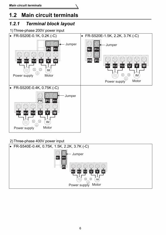
1.2 Main circuit terminals1.2.1 Terminal block layout1)Three-phase 200V power input• FR-S520E-0.1K, 0.2K (-C) • FR-S520E-1.5K, 2.2K, 3.7K (-C)
• FR-S520E-0.4K, 0.75K (-C)
2)Three-phase 400V power input• FR-S540E-0.4K, 0.75K, 1.5K, 2.2K, 3.7K (-C)
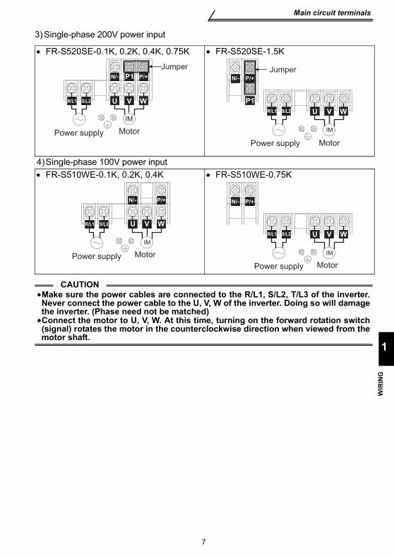
4)Single-phase 100V power input• FR-S510WE-0.1K, 0.2K, 0.4K • FR-S510WE-0.75K
CAUTION•Make sure the power cables are connected to the R/L1, S/L2, T/L3 of the inverter.Never connect the power cable to the U, V, W of the inverter. Doing so will damagethe inverter. (Phase need not be matched)
•Connect the motor to U, V, W. At this time, turning on the forward rotation switch(signal) rotates the motor in the counterclockwise direction when viewed from themotor shaft.
P1
Motor
Jumper
U V W
IM
Power supply
R/L1 S/L2
P/+N/-
P1
Jumper
Motor
U V W
IM
Power supply
P/+N/-
R/L1 S/L2
Motor
U V W
IM
Power supply
R/L1 S/L2
P/+N/-
Motor
U V W
IM
Power supply
P/+N/-
R/L1 S/L2
8
Main circuit terminals
1.2.2 Cables, wiring length, and crimping terminalsThe following table indicates a selection example for the wiring length of 20m. 1) Three-phase 200V power input
2) Three-phase 400V power input
3) Single-phase 200V power input
4) Single-phase 100V power input
Wiring length100m maximum. (50m maximum for the FR-S540E-0.4K.)
Applied Inverter
Ter-minalScrewsize
Tight-ening
TorqueN⋅m
Crimping Terminal
Cable SizeHIV cable
(mm2)AWG
PVC cable(mm2)
R, S, T U, V, W R, S, T U, V, W R, S, T U, V, W R, S, T U, V, WFR-S520E-0.1K to 0.75K (-C) M3.5 1.2 2-3.5 2-3.5 2 2 14 14 2.5 2.5
CAUTION•When the wiring length of the 0.1K and 0.2K of the three-phase 200V, single-phase 200V, and single-phase 100V class and the 0.4K and 0.75K of the three-phase 400V class is 30m or more, set the carrier frequency to 1kHz.
•When automatic torque boost is selected in Pr. 98 "automatic torque boostselection (motor capacity)", the wiring length should be 30m maximum. (Referto page 132.)
9
Main circuit terminals
1
WIR
ING
1.2.3 Wiring instructions
1) Use crimping terminals with insulation sleeve to wire the power supply and motor.
2) Application of power to the output terminals (U, V, W) of the inverter will damage theinverter. Never perform such wiring.
3) After wiring, wire offcuts must not be left in the inverter.Wire offcuts can cause an alarm, failure or malfunction. Always keep the inverterclean.When drilling mounting holes in an enclosure etc., take care not to allow chips andother foreign matter to enter the inverter.
4) Use cables of the recommended size to make a voltage drop 2% maximum.If the wiring distance is long between the inverter and motor, a main circuit cablevoltage drop will cause the motor torque to decrease especially at the output of alow frequency.
5) For long distance wiring, the fast-response current limit function may be reduced orthe devices connected to the secondary side may malfunction or become faultyunder the influence of a charging current due to the stray capacity of wiring.Therefore, note the maximum overall wiring length.
6) Electromagnetic wave interferenceThe input/output (main circuit) of the inverter includes high frequency components,which may interfere with the communication devices (such as AM radios) used nearthe inverter. In this case, install a FR-BIF(-H) optional capacitor type filter (for useon the input side only) or FR-BSF01 or FR-BLF common mode filter to minimizeinterference.
7) Do not install a power capacitor, surge suppressor or capacitor type filter (FR-BIF(-H) option) on the output side of the inverter.This will cause the inverter to trip or the capacitor and surge suppressor to bedamaged. If any of the above devices are connected, remove them. (When usingthe FR-BIF(-H) capacitor type filter with a single-phase power supply, connect it tothe input side of the inverter after isolating the T phase securely.)
8) Before starting wiring or other work after the inverter is operated, wait for at least 10minutes after the power supply has been switched off, and check that there are noresidual voltage using a tester or the like. The capacitor is charged with highvoltage for some time after power off and it is dangerous.
Main circuit terminals
10
1.2.4 Selection of peripheral devicesCheck the inverter type of the inverter you purchased. Appropriate peripheral devicesmust be selected according to the capacity.Refer to the following list and prepare appropriate peripheral devices:1) Three-phase 200V power input
2) Three-phase 400V power input
MotorOutput (kW)
Applied Inverter Type
Moulded Case Circuit Breaker (MCCB *1, 4) orEarth Leakage Circuit Breaker (ELB) (Refer to page 12) (*2, 4)
*1. •Select the MCCB according to the power supply capacity.• Install one MCCB per inverter.
INV
INV
IM
IM
MCCB
MCCB
Main circuit terminals
12
1.2.5 Leakage current and installation of earth (ground) leakage circuit breaker
Due to static capacitances existing in the inverter I/O wiring and motor, leakagecurrents flow through them. Since their values depend on the static capacitances,carrier frequency, etc., take the following countermeasures.(1) To-earth (ground) leakage currents
Leakage currents may flow not only into the inverter's own line but also into theother line through the earth (ground) cable, etc.These leakage currents may operate earth (ground) leakage circuit breakers andearth (ground) leakage relays unnecessarily.
Countermeasures• If the carrier frequency setting is high, decrease the carrier frequency (Pr. 72) of the
inverter.Note that motor noise increases. Selection of Soft-PWM control (Pr. 70) will make itunoffending. (Factory setting)
• By using earth leakage circuit breakers designed for harmonic and surgesuppression in the inverter's own line and other line, operation can be performedwith the carrier frequency kept high (with low noise).
Main circuit terminals
WIR
ING
13
1
(2) Line-to-line leakage currents
Countermeasures• Use the electronic thermal relay function of the inverter.• Decrease the carrier frequency. Note that motor noise increases. Selection of
Soft-PWM (Pr. 70) makes it unoffending.To ensure that the motor is protected against line-to-line leakage currents, it isrecommended to use a temperature sensor to directly detect motor temperature.
Installation and selection of moulded case circuit breakerInstall a moulded case circuit breaker (MCCB) on the power receiving side toprotect the wiring of the inverter primary side. Select the MCCB according to thepower supply side power factor (which depends on the power supply voltage, outputfrequency and load). Especially for a completely electromagnetic MCCB, one of aslightly large capacity must be selected since its operation characteristic varies withharmonic currents. (Check it in the data of the corresponding breaker.) As an earth(ground) leakage breaker, use the Mitsubishi earth (ground) leakage breakerdesigned for harmonics and surge suppression. (Refer to page 10 for therecommended models.)
Harmonics of leakage currents flowing in static capacities between the inverter output cables may operate the external thermal relay unnecessarily.
CAUTION•Select the MCCB according to the inverter power supply capacity.•Install one MCCB per inverter.
Line-to-Line Leakage Current Path
InverterPower supply
IM
Thermal relay
Line static capacitances
MCCB Motor
Main circuit terminals
14
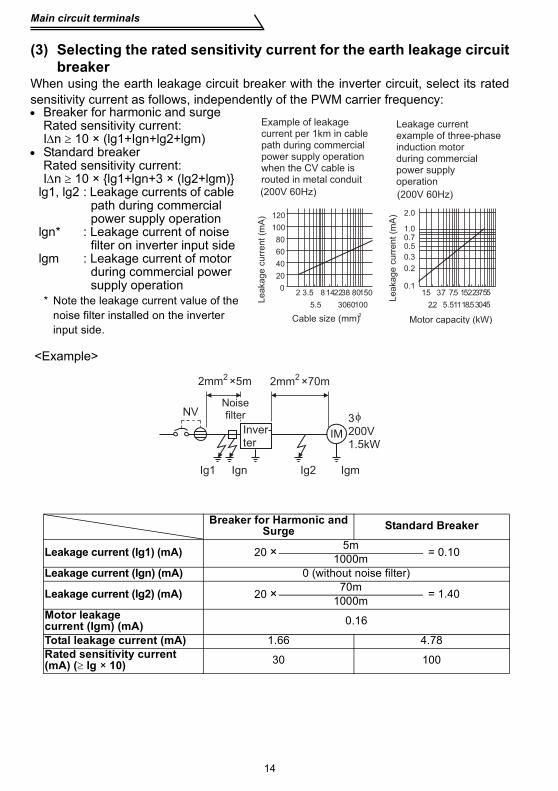
(3) Selecting the rated sensitivity current for the earth leakage circuitbreaker
When using the earth leakage circuit breaker with the inverter circuit, select its ratedsensitivity current as follows, independently of the PWM carrier frequency:• Breaker for harmonic and surge
lg1, lg2 : Leakage currents of cable path during commercial power supply operation
lgn* : Leakage current of noise filter on inverter input side
lgm : Leakage current of motor during commercial power supply operation
* Note the leakage current value of the noise filter installed on the inverter input side.
<Example>
Breaker for Harmonic and Surge Standard Breaker
Leakage current (Ig1) (mA) 20 × 5m = 0.101000mLeakage current (Ign) (mA) 0 (without noise filter)
Leakage current (Ig2) (mA) 20 × 70m = 1.401000mMotor leakage current (Igm) (mA) 0.16
Total leakage current (mA) 1.66 4.78Rated sensitivity current(mA) (≥ Ig × 10) 30 100
Motor capacity (kW)
Example of leakage current per 1km in cable path during commercial power supply operation when the CV cable is routed in metal conduit
Le
aka
ge
cu
rre
nt
(mA
)
Le
aka
ge
cu
rre
nt
(mA
)
Cable size (mm)2
Leakage current example of three-phase induction motor during commercial power supply operation
(200V 60Hz)(200V 60Hz)
0
20
40
60
80
100
120
2 3.5 8142238 80
5.5 3060100
150 1.5 3.7
2.2
7.5 1522
11
37
30
55
455.5 18.5
2.0
1.00.70.5
0.3
0.2
0.1
NV
Ig1 Ign Ig2 Igm
2mm ×5m 2mm ×70m
IM
3200V1.5kW
Inver-ter
Noise filter
2 2
Main circuit terminals
WIR
ING
15
1
CAUTION•The earth (ground) leakage circuit breaker should be installed to the primary(power supply) side of the inverter.
•In the connection neutral point earthed (grounded) system, the sensitivitycurrent becomes worse for earth (ground) faults on the inverter secondaryside. Earthing (Grounding) must conform to the requirements of national andlocal safety regulations and electrical codes. (NEC section 250, IEC 536 class1 and other applicable standards)
•When the breaker is installed on the secondary side of the inverter, it may beunnecessarily operated by harmonics if the effective value is less than therating. In this case, do not install the breaker since the eddy current andhysteresis loss increase and the temperature rises.
•General products indicate the following models: BV-C1, BC-V, NVB, NV-L, NV-G2N, NV-G3NA, NV-2F, earth (ground) leakage relay (except NV-ZHA), NV withAA neutral wire open-phase protectionThe other models are designed for harmonic and surge suppression: NV-C/NV-S/MN series, NV30-FA, NV50-FA, BV-C2, earth (ground) leakage alarmbreaker (NF-Z), NV-ZHA, NV-H
Main circuit terminals
16
1.2.6 Power-off and magnetic contactor (MC)(1) Inverter input side magnetic contactor (MC)On the inverter's input side, it is recommended to provide an MC for the followingpurposes. (Refer to page 10 for selection)1)To release the inverter from the power supply when the inverter protective function
is activated or the drive becomes faulty (e.g. emergency stop operation)When cycle operation or heavy-duty operation is performed with an optional brakeresistor connected, overheat and burnout of the electrical-discharge resistor can beprevented if a regenerative brake transistor is damaged due to insufficient heatcapacity of the electrical-discharge resistor and excess regenerative brake duty.
2)To prevent any accident due to an automatic restart at restoration of power after aninverter stop made by a power failure
3)To rest the inverter for an extended period of timeThe control power supply for inverter is always running and consumes a little power.When stopping the inverter for an extended period of time, powering off the inverterwill save power slightly.
4)To separate the inverter from the power supply to ensure safe maintenance andinspection workThe inverter's input side MC is used for the above purpose, select class JEM1038-AC3 for the inverter input side current when making an emergency stop duringnormal operation.
(2) Handling of output side magnetic contactorIn principle, do not provide a magnetic contactor between the inverter and motor andswitch it from off to on during operation. If it is switched on during inverter operation, alarge inrush current may flow, stopping the inverter due to overcurrent shut-off. Whenan MC is provided for switching to the commercial power supply, for example, switch iton/off after the inverter and motor have stopped.
REMARKSThe MC may be switched on/off to start/stop the inverter. However, since repeated inrushcurrents at power on will shorten the life of the converter circuit (switching life is about 100,000times), frequent starts and stops must be avoided. Turn on/off the inverter start controllingterminals (STF, STR) to run/stop the inverter.
As shown on the right, always use the start signal (ON or OFF across terminals STF or STR-SD) to make a start or stop. (Refer to page 29)
*1. When the power supplyis 400V class, install astep-down transformer.
Inverter Start/Stop Circuit Example
MCCB
OFFON
MCMC
RA
U
V
W
MC
STF(STR)
RARA
MC
T (*1)
Power
supply
Inverter
To motor
OFF
Operation
Operation ready
Start/Stop
A
B
C
T/L3S/L2R/L1
SD
Main circuit terminals
WIR
ING
17
1
1.2.7 Regarding the installation of the reactorWhen the inverter is installed near a large-capacity power transformer (500kVA ormore with the wiring length of 10m or less) or the power capacitor is to be switched, anexcessive peak current will flow in the power supply input circuit, damaging theconverter circuit. In such a case, always install the reactor (FR-HEL(-H) /FR-BEL(-H)or FR-HAL(-H)/FR-BAL(-H)).
•Three-phase power input
•Single phase power input
REMARKS*When connecting the FR-HEL(-H)/FR-BEL(-H), remove the jumper across terminals P-P1.The wiring length between the FR-HEL(-H)/FR-BEL(-H) and the inverter should be 5mmaximum and as short as possible.Use the cables which are equal in size to those of the main circuit. (Refer to page 8)The single-phase 100V power input model does not allow the DC reactor to be fitted.
MCCBInverter
FR-HAL(-H)/FR-BAL(-H)
Power supply
R
S
T Z
Y
XU
VW
P1
FR-HEL(-H)/FR-BEL(-H)(*)
P
R
S
T
0 10Wiring length (m)
500
1500
1000
Pow
er s
uppl
y eq
uipm
ent
capa
city
(kV
A)
Reactor installation range
MCCBInverter
FR-HAL(-H)/FR-BAL(-H)
Power supply
R
S
T Z
Y
XU
VW
P1
FR-HEL(-H)/FR-BEL(-H)(*)
P
R
S
Main circuit terminals
18
1.2.8 Regarding noise and the installation of a noise filterSome noise enters the inverter causing it to malfunction and others are generated bythe inverter causing the malfunction of peripheral devices. Though the inverter isdesigned to be insusceptible to noise, it handles low-level signals, so it requires thefollowing general countermeasures to be taken.
(1) General countermeasures• Do not run the power cables (I/O cables) and signal cables of the inverter in parallel
with each other and do not bundle them.• Use twisted shield cables for the detector connecting and control signal cables and
connect the sheathes of the shield cables to terminal SD.• Earth (Ground) the inverter, motor, etc. at one point.• Capacitances exist between the inverter's I/O wiring, other cables, earth (ground)
and motor, through which leakage currents flow to cause the earth leakage circuitbreaker, earth (ground) leakage relay and external thermal relay to operateunnecessarily. To prevent this, take appropriate measures, e.g. set the carrierfrequency in Pr. 72 to a low value, use an earth (ground) leakage circuit breakerdesigned for suppression of harmonics and surges, and use the electronic thermalrelay function built in the inverter.
• The input and output of the inverter main circuit include high-degree harmonics,which may disturb communication devices (AM radios) and sensors used near theinverter. In this case, install a FR-BIF(-H) optional capacitor type filter (for use on theinput side only) or FR-BSF01 common mode filter to minimize interference.
<Noise reduction examples>
Power supplyfor sensor
Inverter
power supply
Control power supply
Control
box
Reduce carrier
frequency.
IMFR-BSF01
FR-BSF01
SensorUse twisted pair shielded cable.
Motor
Install filter
on inverter's output side.
Inverter
FR-BIF
Install filter FR-BIF
on inverter's input side.
FR-BSF01
FR-BSF01Install filter
on inverter's input side.
Separate inverter and power
line by more than 30cm and
at least 10cm from sensor circuit.
Do not earth (ground)
control box directly.
Do not earth (ground) control cable.
Use 4-core cable for motor
power cable and use one
cable as earth (ground) cable.
Do not earth (ground) shield but connect
it to signal common cable.
Main circuit terminals
WIR
ING
19
1
1.2.9 Earthing (Grounding) precautions
Leakage currents flow in the inverter. To prevent an electric shock, the inverter andmotor must be earthed (grounded). Earthing (Grounding) must conform to therequirements of national and local safety regulations and electrical codes. (NEC section 250, IEC 536 class 1 and other applicable standards)
Use the dedicated earth (ground) terminal to earth (ground) the inverter. (Do not usethe screw in the casing, chassis, etc.)Use a tinned* crimping terminal to connect the earth (ground) cable. Whentightening the screw, be careful not to damage the threads.*Plating should not include zinc.
Use the thickest possible earth (ground) cable. Use the cable whose size is equal toor greater than that indicated in the following table, and minimize the cable length. The earthing (grounding) point should be as near as possible to the inverter.
For use as a product compliant with the Low Voltage Directive, use PVC cablewhose size is indicated within parentheses.
Earth (Ground) the motor on the inverter side using one wire of the 4-core cable.
Motor Capacity Earth (Ground) Cable Size (Unit: mm2)200V class, 100V class 400V class
2.2kW or less 2 (2.5) 2 (2.5)3.7kW 3.5 (4) 2 (4)
20
Main circuit terminals
1.2.10 Power supply harmonicsThe inverter may generate power supply harmonics from its converter circuit to affectthe power generator, power capacitor etc. Power supply harmonics are different fromnoise and leakage currents in source, frequency band and transmission path. Take thefollowing countermeasure suppression techniques.
The following table indicates differences between harmonics and noise:Item Harmonics Noise
Frequency Normally 40th to 50th degrees or less (up to 3kHz or less)
High frequency (several 10kHz to 1GHz order)
Environment To-electric channel, power impedance To-space, distance, wiring pathQuantitative understanding Theoretical calculation possible Random occurrence,
quantitative grasping difficult
Generated amount Nearly proportional to load capacityChange with current variation ratio (larger as switching speed increases)
Affected equipment immunity Specified in standard per equipment Different depending on maker's
equipment specificationsSuppression example Provide reactor. Increase distance.
Suppression techniqueHarmonic currents produced on the power supply side by the inverter change with such conditions as whether there are wiring impedances and a DC reactor (FR-HEL(-H)/FR-BEL(-H) or FR-HAL(-H)/FR-BAL(-H)) and the magnitudes of output frequency and output current on the load side.For the output frequency and output current, we understand that they should be calculated in the conditions under the rated load at the maximum operating frequency.
CAUTIONThe power factor improving capacitor and surge suppressor on the inverteroutput side may be overheated or damaged by the high frequency componentsof the inverter output. Also, since an excessive current flows in the inverter toactivate overcurrent protection, do not provide a capacitor and surgesuppressor on the inverter output side when the motor is driven by the inverter.To improve the power factor, insert a reactor on the inverter's primary side orDC circuit. For full information, refer to page 17.
Inve
rte
rMCCB
Do not provide power factor
improving capacitor.
Motor
IM
FR-HAL(-H)/FR-BAL(-H)
FR-HEL(-H)/FR-BEL(-H)
Main circuit terminals
WIR
ING
21
1
1.2.11 Harmonic suppression guidelineHarmonic currents flow from the inverter to a power receiving point via a powertransformer. The harmonic suppression guideline was established to protect otherconsumers from these outgoing harmonic current.The three-phase 200V input specifications 3.7kW or less are previously covered by"Harmonic suppression guideline for household appliances and general-purposeproducts" and other models are covered by "Harmonic suppression guideline forconsumers who receive high voltage or special high voltage". However, the general-purpose inverter has been excluded from the target products covered by "Harmonicsuppression guideline for household appliances and general-purpose products" inJanuary 2004. Later, this guideline was repealed on September 6, 2004. All capacitiesof all models are now target products of "Harmonic suppression guideline forconsumers who receive high voltage or special high voltage" (hereinafter referred toas "Guideline for specific consumers")."Guideline for specific consumers"This guideline sets forth the maximum values of harmonic currents outgoing from ahigh-voltage or especially high-voltage consumer who will install, add or renewharmonic generating equipment. If any of the maximum values is exceeded, thisguideline requires that consumer to take certain suppression measures.Table 1 Maximum Values of Outgoing Harmonic Currents per 1kW Contract Power
Received Power Voltage 5th 7th 11th 13th 17th 19th 23rd Over 23rd
(1) Application of the guideline for specific consumers
* K42=0.35 is a value when the reactor value is 20%. Since a 20% reactor is large andconsidered to be not practical, K42=1.67 is written as conversion factor for a 5% reactor inthe technical data JEM-TR201 of the Japan Electric Machine Industry Association and thisvalue is recommended for calculation for the actual practice.
Table 2 Conversion Factors for FR-S500 SeriesCircuit Type Conversion Factor (Ki)
Table 3 Equivalent Capacity LimitsReceived Power Voltage Reference Capacity
6.6kV 50 kVA22/33 kV 300 kVA66kV or more 2000 kVA
Not more than
reference capacity
New installation/addition/
renewal of equipment
Calculation of equivalent
capacity sum
Sum of equivalent
capacities
Over reference
capacity
Calculation of outgoing
harmonic current
Is outgoing harmonic
current equal to or lower
than maximum value?
Not more than
maximum value
Harmonic suppression
technique is not required.
Over maximum value
Harmonic suppression
technique is required.
Main circuit terminals
WIR
ING
23
1
* The harmonic contents for "single-phase bridge/with reactor" in the table 4 are values whenthe reactor value is 20%. Since a 20% reactor is large and considered to be not practical,harmonic contents when a 5% reactor is used is written in the technical data JEM-TR201 ofthe Japan Electric Machine Industry Association and this value is recommended forcalculation for the actual practice.
1) Calculation of equivalent capacity (P0) of harmonic generating equipmentThe "equivalent capacity" is the capacity of a 6-pulse converter converted from thecapacity of consumer's harmonic generating equipment and is calculated with thefollowing equation. If the sum of equivalent capacities is higher than the limit inTable 3, harmonics must be calculated with the following procedure:
2) Calculation of outgoing harmonic currentOutgoing harmonic current = fundamental wave current (value converterd from
received power voltage) × operation ratio × harmoniccontent
• Operation ratio: Operation ratio = actual load factor × operation time ratio during 30 minutes
• Harmonic content: Found in Table 4.
Table 4 Harmonic Contents (Values of the fundamental current is 100%)Reactor 5th 7th 11th 13th 17th 19th 23rd 25th
Three-phase bridge (capacitor smoothed)
Not used 65 41 8.5 7.7 4.3 3.1 2.6 1.8Used (AC side) 38 14.5 7.4 3.4 3.2 1.9 1.7 1.3Used (DC side) or with filter pack 30 13 8.4 5.0 4.7 3.2 3.0 2.2
Used (AC, DC sides) 28 9.1 7.2 4.1 3.2 2.4 1.6 1.4
P0=Σ (Ki × Pi) [kVA]Ki: Conversion factor (refer to Table 2)Pi: Input rated capacity of harmonic
generating equipment* [kVA]i: Number indicating the conversion
circuit type
* Input rated capacity: Determined by the capacity of the applied motor and found in Table 5. It should be noted that the rated capacity used here is used to calculate a generated harmonic amount and is different from the power supply capacity required for actual inverter drive.
Main circuit terminals
24
3) Harmonic suppression technique requirementIf the outgoing harmonic current is higher than; maximum value per 1kW (contractpower) × contract power, a harmonic suppression technique is required.
4) Harmonic suppression techniques
Table 5 Rated Capacities and Outgoing Harmonic Currents for Inverter Drive
Applied Motor(kW)
RatedCurrent [A]
6.6kVEquivalent of fundamental wave input
current (mA)
Input rated
capacity(kVA)
Outgoing Harmonic Current Converted from 6.6kV (mA)
Install a reactor (ACL) in the AC side of the inverter or a reactor (DCL) in its DC side or both to suppress outgoing harmonic currents.
2Installation of power factor improving capacitor
When used with a series reactor, the power factor improving capacitor has an effect of absorbing harmonic currents.
3Transformer multi-phase operation
Use two transformers with a phase angle difference of 30° as in -Δ, Δ-Δ combination to provide an effect corresponding to 12 pulses, reducing low-degree harmonic currents.
4Passive(AC filter)
A capacitor and a reactor are used together to reduce impedances at specific frequencies, producing a great effect of absorbing harmonic currents.
5
Active filter This filter detects the current of a circuit generating a harmonic current and generates a harmonic current equivalent to a difference between that current and a fundamental wave current to suppress a harmonic current at a detection point, providing a great effect of absorbing harmonic currents.
25
Main circuit terminals
1
WIR
ING
1.2.12 Inverter-driven 400V class motorIn the PWM type inverter, a surge voltage attributable to wiring constants is generatedat the motor terminals. Especially for a 400V class motor, the surge voltage maydeteriorate the insulation. When the 400V class motor is driven by the inverter,consider the following measures:
•MeasuresIt is recommended to take either of the following measures:(1) Rectifying the motor insulation
For the 400V class motor, use an insulation-enhanced motor. Specifically1) Specify the "400V class inverter-driven, insulation-enhanced motor".2) For the dedicated motor such as the constant-torque motor and low-vibration
motor, use the "inverter-driven, dedicated motor".
(2) Suppressing the surge voltage on the inverter sideOn the secondary side of the inverter, connect the optional surge voltage suppression filter (FR-ASF-H).
CAUTIONWhen the wiring length between the motor and inverter is 40m or more, takethe above countermeasure and also set the long wiring mode in Pr. 70 "Soft-PWM setting". (Refer to page 113 for Pr. 70.)
26
How to use the control circuit terminals
1.3 How to use the control circuit terminals
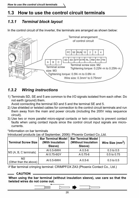
1.3.1 Terminal block layout
In the control circuit of the inverter, the terminals are arranged as shown below:
1.3.2 Wiring instructions1) Terminals SD, SE and 5 are common to the I/O signals isolated from each other. Do
not earth (ground) them. Avoid connecting the terminal SD and 5 and the terminal SE and 5.
2) Use shielded or twisted cables for connection to the control circuit terminals and runthem away from the main and power circuits (including the 200V relay sequencecircuit).
3) Use two or more parallel micro-signal contacts or twin contacts to prevent contactfaults when using contact inputs since the control circuit input signals are micro-currents.
*Information on bar terminalsIntroduced products (as of September, 2006): Phoenix Contact Co.,Ltd.
Bar terminal crimping terminal: CRIMPFOX ZA3 (Phoenix Contact Co., Ltd.)
Terminal Screw SizeBar Terminal Model
(With Insulation Sleeve)
Bar Terminal Model (Without Insulation
Sleeve)Wire Size (mm2)
M3 (A, B, C terminals)Al 0.5-6WH A 0.5-6 0.3 to 0.5Al 0.75-6GY A 0.75-6 0.5 to 0.75
M2(Other than the above) Al 0.5-6WH A 0.5-6 0.3 to 0.5
CAUTIONWhen using the bar terminal (without insulation sleeve), use care so that thetwisted wires do not come out.
RL FM
10 2 5 4
RM RH
Terminal arrangement
of control circuit
RUN
STR
PC SE
SD SD STF
Terminal screw
size: M3
A B C
Terminal screw size: M2Tightening torque: 0.22N m to 0.25N m
Tightening torque: 0.5N m to 0.6N m
Wire size: 0.3mm2 to 0.75mm2
How to use the control circuit terminals
WIR
ING
27
1
1.3.3 Changing the control logicThe input signals are set to sink logic.To change the control logic, the jumper connector under the setting dial must be moved to the other position.
Change the jumper connector position using tweezers, a pair of long-nose pliers etc.Change the jumper connector position before switching power on.
CAUTION•Make sure that the front cover is installed securely.•The front cover is fitted with the capacity plate and the inverter unit with therating plate. Since these plates have the same serial numbers, always replacethe removed cover onto the original inverter.
•The sink-source logic change-over jumper connector must be fitted in onlyone of those positions. If it is fitted in both positions at the same time, theinverter may be damaged.
1) Sink logic type• In this logic, a signal switches on when a current flows from the corresponding
signal input terminal.Terminal SD is common to the contact input signals. Terminal SE is common to theopen collector output signals.
• Use terminal PC as a common terminal, and perform wiring as shown on the right. (Do not connect terminal SD of the inverter with terminal 0V of the external power supply. When using terminals PC-SD as a 24VDC power supply, do not install a power supply in parallel in the outside of the inverter. Doing so may cause a malfunction due to undesirable current.)
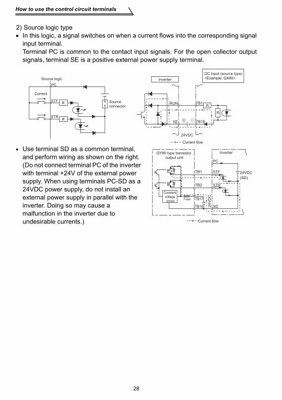
2) Source logic type• In this logic, a signal switches on when a current flows into the corresponding signal
input terminal.Terminal PC is common to the contact input signals. For the open collector outputsignals, terminal SE is a positive external power supply terminal.
• Use terminal SD as a common terminal, and perform wiring as shown on the right. (Do not connect terminal PC of the inverter with terminal +24V of the external power supply. When using terminals PC-SD as a 24VDC power supply, do not install an external power supply in parallel with the inverter. Doing so may cause a malfunction in the inverter due to undesirable currents.)
Current
PC
STFR
STR
Source logic
Source connector
R
DC input (source type) <Example: QX80>
24VDC
RUN
SE
TB1
TB18
R
Inverter
R
Current flow
QY80 type transistor output unit
Constant voltage circuit
PC
TB1
TB2
TB17Fuse
TB18
STF
STR
SD
Inverter
24VDC
(SD)
24
VD
C
Current flow
Input terminals
WIR
ING
29
1
1.4 Input terminals
1.4.1 Run (start) and stop (STF, STR, STOP)To start and stop the motor, first switch on the input power supply of the inverter to turnon the magnetic contactor at the operation-ready when there is a magnetic contactoron the input side, then start the motor with the forward or reverse rotation start signal.(1) Two-wire type connection (STF, STR)A two-wire type connection is shown on the right.1) The forward/reverse rotation
signal is used as both the start and stop signals. Switch on either of the forward and reverse rotation signals to start the motor in the corresponding direction. Switch on both or switch off the start signal during operation to decelerate the inverter to a stop.
2) The frequency setting signal may either be given by entering 0 to 5VDC (or 0 to 10VDC) across frequency setting input terminals 2-5 or by setting the required values in Pr. 4 to Pr. 6 "multi-speed setting" (high, middle, low speeds). (For multi-speed operation, refer to page 33.)
3) After the start signal has been input, the inverter starts operating when thefrequency setting signal reaches or exceeds the "starting frequency" set in Pr. 13(factory-set to 0.5Hz).If the motor load torque is large or the "torque boost" set in Pr. 0 is small, operationmay not be started due to insufficient torque until the inverter output frequencyreaches about 3 to 6Hz.If the "minimum frequency" set in Pr. 2 (factory setting = 0Hz) is 6Hz, for example,merely entering the start signal causes the running frequency to reach theminimum frequency of 6Hz according to the "acceleration time" set in Pr. 7.
4) To stop the motor, operate the DC injection brake for the period of "DC injectionbrake operation time" set in Pr. 11 (factory setting = 0.5s) at not more than the DCinjection brake operation frequency or at not more than 0.5Hz.To disable the DC injection brake function, set 0 in either of Pr. 11 "DC injectionbrake operation time" or Pr. 12 "DC injection brake voltage".In this case, the motor is coasted to a stop at not more than the frequency set in Pr. 10 "DC injection brake operation frequency" (0 to 120Hz variable) or at notmore than 0.5Hz (when the DC injection brake is not operated).
5) If the reverse rotation signal is input during forward rotation or the forward rotationsignal is input during reverse rotation, the inverter is decelerated and thenswitched to the opposite output without going through the stop mode.
ON
MCCBPower supply
Forward rotation start
Reverse rotation start
STF
STR (Pr. 63 = "- - -" )
Inverter
Ou
tpu
t fr
eq
ue
ncy
Time
2-wire type connection example
SD
R, S, T
Across STF-SD(STR)
Input terminals
30
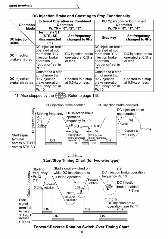
*1: Also stopped by the . Refer to page 115.
Start/Stop Timing Chart (for two-wire type)
Forward-Reverse Rotation Switch-Over Timing Chart
DC Injection Brake and Coasting to Stop Functionality
OperationMode
DC Injection Brake
External Operation or Combined Operation
Pr. 79 = "0", "2", "3"
PU Operation or Combined Operation
Pr. 79 = "0", "1", "4"Terminals STF
(STR)-SD disconnected
(*1)
Set frequency changed to 0Hz Stop key Set frequency
changed to 0Hz
DC injection brake enabled
DC injection brake operated at not more than "DC injection brake operation frequency" set in Pr. 10
DC injection brake operated at 0.5Hz or less.
DC injection brake operated at not more than "DC injection brake operation frequency" set in Pr. 10
DC injection brake operated at 0.5Hz or less.
DC injection brake disabled
Coasted to a stop at not more than "DC injection brake operation frequency" set in Pr. 10
Coasted to a stop at 0.5Hz or less.
Coasted to a stop at not more than "DC injection brake operation frequency" set in Pr. 10
Coasted to a stop at 0.5Hz or less.
STOPRESET
DC injectionbrake operation time Pr. 11
Out
put f
requ
ency
Starting frequencyPr.13(*1)0.5Hz
ON
DC injection brakeoperation frequency Pr. 103Hz
0.5sDC injectionbrake operationtime Pr. 11
0.5Hz0.5s
ON
0.5Hz
ON
3Hz
Coasted to a stop
Time
DC injection brake not operated
DC injection brake disabledDC injection brake enabled
Start signalterminal
(*4)
(*3) (*3)
(*2)
Across STF-SDAcross STR-SD
Out
put f
requ
ency
Starting frequencyPr.13(*1)
0.5HzForwardrotation
Forwardrotation
3Hz
3Hz
Start signal switched on while DC injection brake is being operated
DC injection brake operationfrequency Pr. 10
DC injectionbrake enabled
Time
DC injection brake operation time Pr. 11
0.5s
ON
ON ON
ON
Reverserotation
0.5Hz
Start signal terminal (*3)
(*4)
Across STF-SDAcross STR-SD
Input terminals
WIR
ING
31
1
REMARKS*1. The "starting frequency" in Pr. 13 (factory-set to 0.5Hz) may be set between 0 and 60Hz.*2. If the next start signal is given during DC injection brake operation, the DC injection brake
is disabled and restart is made.*3. The "DC injection brake operation time" in Pr. 11 (factory-set to 0.5s) may be set between
0 and 10s.*4. The frequency at which the motor is coasted to a stop is not more than the "DC injection
brake operation frequency" set in Pr. 10 (factory setting = 3Hz; may be set between 0 and120Hz) or not more than 0.5Hz.
*5. The "starting frequency" in Pr. 13, "DC injection brake operation time" in Pr. 11 and "DCinjection brake operation frequency" in Pr. 10 are the factory-set values.
(2) Three-wire type connection (STF, STR, STOP)A three-wire type connection is shown on the right. Assign the start self-holding signal (STOP) to any of the input terminals.To make a reverse rotation start, set Pr. 63 to "- - -" (factory setting).1) Turning the STOP signal on makes start
self-holding function valid. In this case, the forward/reverse rotation signal functions only as a start signal.(Note) Assign the stop signal to any of
Pr. 60 to Pr. 62 (input terminal function selection).
2) Even if the start signal STF (STR) is turned on once then off, the start signal is kept on and starts the inverter. When changing the direction of rotation, turn the start signal STR (STF) on once and then off.
3) To stop the inverter, turning off the STOP signal once decelerates it to a stop.For the frequency setting signal and the operation of DC injection brake at a stop time, refer to paragraphs 2) to 4) in (1) Two-wire type connection. The right diagram shows 3-wire type connection.
4) When the JOG signal is on, the STOP signal is invalid and the JOG signal hasprecedence.
5) When the output stop signal MRS is turned on, the inverter output is shutoff.However, self-holding function is not deactivated and the start signal is held.
Reverse rotation start
MCCB
Time
STF
STR (Pr. 63 = "- - -" )
STOP
Start
Stop
ON
ON ON
OFF
Power supply
Inverter
Ou
tpu
t fr
eq
ue
ncy
Stop
Forward rotation start
3-wire type connection example
SD
R, S, T
Input terminals
32
1.4.2 Connection of frequency setting potentiometer and output frequency meter (10, 2, 5, 4, AU)
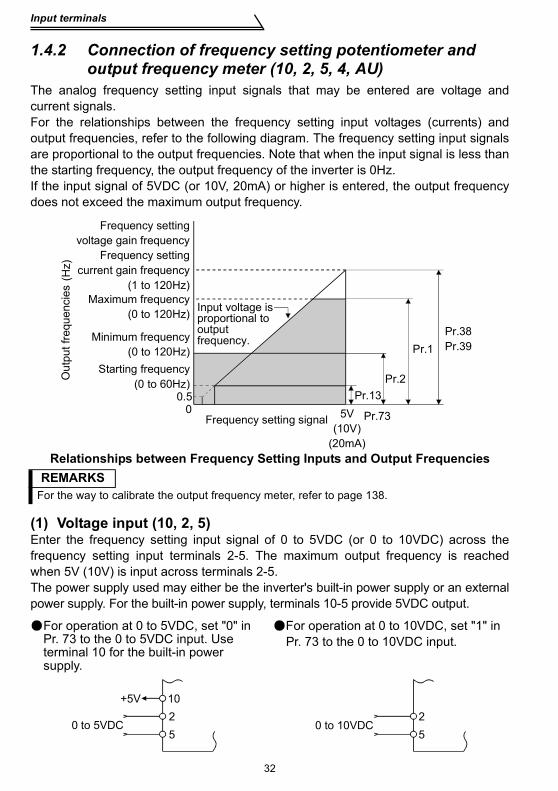
The analog frequency setting input signals that may be entered are voltage andcurrent signals.For the relationships between the frequency setting input voltages (currents) andoutput frequencies, refer to the following diagram. The frequency setting input signalsare proportional to the output frequencies. Note that when the input signal is less thanthe starting frequency, the output frequency of the inverter is 0Hz.If the input signal of 5VDC (or 10V, 20mA) or higher is entered, the output frequencydoes not exceed the maximum output frequency.
Relationships between Frequency Setting Inputs and Output Frequencies
(1) Voltage input (10, 2, 5)Enter the frequency setting input signal of 0 to 5VDC (or 0 to 10VDC) across thefrequency setting input terminals 2-5. The maximum output frequency is reachedwhen 5V (10V) is input across terminals 2-5.The power supply used may either be the inverter's built-in power supply or an externalpower supply. For the built-in power supply, terminals 10-5 provide 5VDC output.
REMARKSFor the way to calibrate the output frequency meter, refer to page 138.
For operation at 0 to 5VDC, set "0" in Pr. 73 to the 0 to 5VDC input. Use terminal 10 for the built-in power supply.
For operation at 0 to 10VDC, set "1" in Pr. 73 to the 0 to 10VDC input.
Maximum frequency(0 to 120Hz)
Minimum frequency(0 to 120Hz)
Starting frequency(0 to 60Hz)
0.50
Out
put f
requ
enci
es (H
z)
Input voltage is proportional to output frequency.
Pr.38Pr.39Pr.1
Pr.2Pr.13
Pr.735V(10V)
(20mA)
Frequency setting signal
Frequency settingvoltage gain frequency
Frequency settingcurrent gain frequency
(1 to 120Hz)
+5V 1025
0 to 5VDC 0 to 10VDC25
Input terminals
WIR
ING
33
1
(2) Current input (4, 5, AU)To automatically perform operation under constant pressure or temperature controlusing a fan, pump etc., enter the controller output signal of 4 to 20mADC acrossterminals 4-5.Terminals AU-SD must be shorted to use the 4 to 20mADC signal for operation.(Assign the signal AU using any of Pr. 60 to Pr. 63.)When the multi-speed signal is input, the current input is ignored.
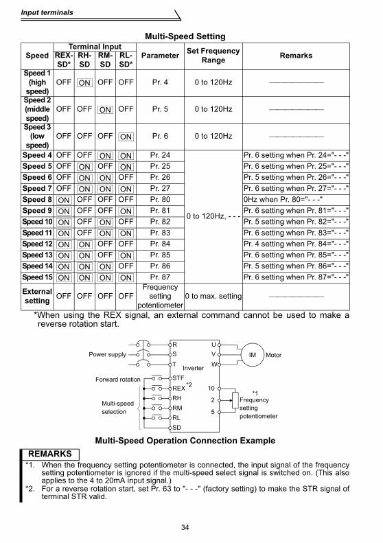
1.4.3 External frequency selection (REX, RH, RM, RL)Up to 15 speeds (*) may be selected for an external command forward rotation start orup to 7 speeds for an external command reverse rotation start according to thecombination of connecting the multi-speed select terminals REX, RH, RM and RL-SD,and multi-speed operation can be performed as shown below by shorting the startsignal terminal STF (STR)-SD.Speeds (frequencies) may be specified as desired from the operation panel orparameter unit as listed below.
CAUTION• * Change the setting of Pr. 63 "STR terminal function selection" to "8", and
assign and use as the 15-speed select signal (REX).Has precedence over the main speed setting signal (0 to 5V, 0 to 10V, 4 to20mADC).
Automatic/manual signal switching
Automatic signal4-20mADC
AU
10254
Inverter
OFFON
OperationManual operationFrequency setting
potentiometerAutomaticoperation4 to 20mA
Manual-Automatic Switching
Manual operation0 to 5V
(0 to 10V)
SD
Across AU-SD
REX
Speed 1(high speed)
Speed 5Speed 6
Speed 7
Time
ON ON ON ONRM
ONONONRL
RHON ON ON ON
Out
put f
requ
ency
(Hz)
(low speed)Speed 3
Speed 2(middle speed)
Speed 4
Time
Speed 9
Speed 10Speed 11
Speed 12Speed 13
Speed 14Speed 15
ON ON ON ONRH
ON ON ON ONRM
ON ON ON ONRL
ONON ON ON ON ON ON ONREX
Out
put f
requ
ency
(Hz)
Speed 8
Input terminals
34
*When using the REX signal, an external command cannot be used to make areverse rotation start.
Multi-Speed Operation Connection Example
Multi-Speed Setting
SpeedTerminal Input
Parameter Set Frequency Range RemarksREX-
SD*RH-SD
RM-SD
RL-SD*
Speed 1 (high
speed)OFF OFF OFF Pr. 4 0 to 120Hz ⎯⎯⎯⎯⎯⎯⎯
Speed 2 (middle speed)
OFF OFF OFF Pr. 5 0 to 120Hz ⎯⎯⎯⎯⎯⎯⎯
Speed 3 (low
speed)OFF OFF OFF Pr. 6 0 to 120Hz ⎯⎯⎯⎯⎯⎯⎯
Speed 4 OFF OFF Pr. 24
0 to 120Hz, - - -
Pr. 6 setting when Pr. 24="- - -"Speed 5 OFF OFF Pr. 25 Pr. 6 setting when Pr. 25="- - -"Speed 6 OFF OFF Pr. 26 Pr. 5 setting when Pr. 26="- - -"Speed 7 OFF Pr. 27 Pr. 6 setting when Pr. 27="- - -"Speed 8 OFF OFF OFF Pr. 80 0Hz when Pr. 80="- - -"Speed 9 OFF OFF Pr. 81 Pr. 6 setting when Pr. 81="- - -"Speed 10 OFF OFF Pr. 82 Pr. 5 setting when Pr. 82="- - -"Speed 11 OFF Pr. 83 Pr. 6 setting when Pr. 83="- - -"Speed 12 OFF OFF Pr. 84 Pr. 4 setting when Pr. 84="- - -"Speed 13 OFF Pr. 85 Pr. 6 setting when Pr. 85="- - -"Speed 14 OFF Pr. 86 Pr. 5 setting when Pr. 86="- - -"Speed 15 Pr. 87 Pr. 6 setting when Pr. 87="- - -"
Externalsetting OFF OFF OFF OFF
Frequencysetting
potentiometer0 to max. setting ⎯⎯⎯⎯⎯⎯⎯
REMARKS*1. When the frequency setting potentiometer is connected, the input signal of the frequency
setting potentiometer is ignored if the multi-speed select signal is switched on. (This alsoapplies to the 4 to 20mA input signal.)
*2. For a reverse rotation start, set Pr. 63 to "- - -" (factory setting) to make the STR signal ofterminal STR valid.
ON
ON
ON
ON ONON ONON ONON ON ON
ONON ONON ONON ON ONON ONON ON ONON ON ONON ON ON ON
10
2
5
Power supply
Forward rotation
Multi-speed selection
Frequency setting potentiometer
Inverter
UVW
STFREXRHRMRL
IM Motor
*2*1
RST
SD
Input terminals
WIR
ING
35
1
1.4.4 Indicator connection and adjustment (FM)The output frequency, etc. of the inverter can be indicated by a DC ammeter of 1mAfull-scale deflection and maximum 300Ω internal resistance or a commerciallyavailable digital indicator which is connected across terminals FM-SD.The indicator can be calibrated from the operation panel or parameter unit. Note thatthe reading varies according to the wiring distance if the indicator is placed away fromthe inverter. In this case, connect a calibration resistor in series with the indicator asshown below and adjust until the reading matches the operation panel or parameterunit indication (indicator monitoring mode).Install the indicator within 200m (50m for the digital indicator) of the inverter andconnect them by at least 0.3mm2 twisted or shielded cables.
Types of Indicators ConnectedREMARKS
* Not needed when calibration is made using the calibration parameter C1 "FM terminalcalibration". This resistor is used when calibration must be made near the frequency meterfor such a reason as a remote frequency meter. Note that the needle of the frequency metermay not deflect to full-scale when the calibration resistor is connected. In this case, use boththe resistor and calibration parameter "C1".
CAUTION•Refer to page 138 for the procedure of indicator adjustment.
Digital indicator
1440 pulses/sFM
SD
Inverter
Analog indicator
Calibration resistor*
(+)
(1mA full-scale)
FM
SD
1mA
Inverter
(-)
Input terminals
36
Output waveform of terminal FMThe output signal of terminal FM has a pulse waveform as shown in the table belowand the number of its pulses is proportional to the inverter output frequency.The output voltage (average voltage) is also proportional to the output frequency.
Terminal FM Output Voltage
*1. 0.5V or less when a DC ammeter of 300Ω or less internal resistance is connected tomeasure the output voltage.
• Analog meterTo adjust the reading of an analog indicator (ammeter), turn the calibration resistor tochange the current.When using the operation panel or parameter unit for adjustment, change the pulsewidth of the output waveform (calibration parameter "C1") (adjust the current throughthe adjustment of the output voltage) to adjust the reading. (For details, refer to page138.)
Specifications
Example of Inverter and Frequency Meter
Output waveform
Number of output pulses
(pulses/second)
Max. 2400 pulses/sSet a full-scale value which achieves 1440 pulses/s.Pr. 55: frequency monitoring
referencePr. 56: current monitoring
referenceOutput voltage
0 to 8VDC max. (*1)(Approx. 5V at 1440 pulses/s)
Adjustment
REMARKSIt is not recommended to use a voltage type indicator because it is easily affected by a voltagedrop, induction noise, etc. and may not provide correct reading if the wiring distance is long.
Inverter
24V
SD
FM
FM
Calibration parameter C1 (Pr. 900)
8V
Input terminals
WIR
ING
37
1
• Digital indicatorSince the digital indicator counts and displays the number of pulses, adjust it fromthe operation panel or parameter unit.The inverter output, at which the reference pulses of 1440 pulses/s are output, canbe set in Pr. 55 when frequency monitoring is used as reference, or in Pr. 56 whencurrent monitoring is used as reference.
[Example] 1. To set the output across FM-SD to 1440 pulses/s at the inverter outputfrequency of 120Hz, set "120" (Hz) in Pr. 55. (Factory setting: 60Hz)
2. To set the output across FM-SD to 1440 pulses/s at the inverter outputcurrent of 15A, set "15" (A) in Pr. 56. (Factory setting: rated invertercurrent)
1.4.5 Control circuit common terminals (SD, 5, SE)Terminals SD, 5, and SE are all common terminals (0V) for I/O signals and are isolatedfrom each other.Terminal SD is a common terminal for the contact input terminals (STF, STR, RH, RM,RL) and frequency output signal (FM).Terminal 5 is a common terminal for the frequency setting analog input signals. Itshould be protected from external noise using a shielded or twisted cable.Terminal SE is a common terminal for the open collector output terminal (RUN).
1.4.6 Signal inputs by contactless switchesIf a transistor is used instead of a contacted switch as shown on the right, the input signals of the inverter can control terminals STF, STR, RH, RM, RL.
REMARKS1.When using an external transistor connected to an external power supply, use terminal PC
to prevent a malfunctions due to undesirable currents. (Refer to page 27.)2.Note that an SSR (solid-state relay) has a relatively large leakage current at OFF time and it
may be accidentally input to the inverter.
+24V
STF, etc.
SD
Inverter
External signal input using transistor
How to use the input signals (assigned terminals RL, RM, RH, STR)
38
1.5 How to use the input signals (assigned terminals RL, RM, RH, STR)
1.5.1 Multi-speed setting (RL, RM, RH, REX signals): Pr. 60 to Pr. 63 setting "0, 1, 2, 8" Remote setting (RL, RM, RH signals): Pr. 60 to Pr. 63 setting "0, 1, 2"
• By entering frequency commands into the RL, RM, RH and REX signals and turningon/off the corresponding signals, you can perform multi-speed operation (15speeds). (For details, refer to page 33.)
• If the operation panel is away from the enclosure, you can perform continuousvariable-speed operation with signal contacts, without using analog signals. (Fordetails, refer to page 104.)
1.5.2 Second function selection (RT signal): Pr. 60 to Pr. 63 setting "3"
1.5.3 Current input selection "AU signal": Pr. 60 to Pr. 63 setting "4"
These terminals can be changed in function by setting Pr. 60 to Pr. 63.
Pr. 60 "RL terminal function selection"
Page 108Pr. 61 "RM terminal function selection"Pr. 62 "RH terminal function selection"Pr. 63 "STR terminal function selection"
Pr. 44 "second acceleration/deceleration time"Pr. 45 "second deceleration time"Pr. 46 "second torque boost"Pr. 47 "second V/F (base frequency)"To set any of the above functions, turn on this "RT signal".
When a fan, pump etc. is used to perform operation of constant- pressure/temperature control, automatic operation can be performed by entering the 4-20mADC output signal of a regulator into across terminals 4-5. When the 4-20mADC signal is used to perform operation, always short the AU signal.
REMARKSThe current input is ignored if the multi-speed signal is input.
STF (STR)
RT
Inverter
Start
Second acceleration/deceleration SD
OFF
Automatic/manualsignal switching
Manual operation Frequency setting
potentiometerAutomatic signal
4-20mADC
AU
10254
Inverter
ON
OperationAutomaticoperation4 to 20mA
Manual operation0 to 5V
(0 to 10V)
SD
Across
AU-SD
How to use the input signals (assigned terminalsRL, RM, RH, STR)
WIR
ING
39
1
1.5.4 Start self-holding selection (STOP signal): Pr. 60 to Pr. 63
setting "5"
1.5.5 Output shut-off (MRS signal): Pr. 60 to Pr. 63 setting "6"Short the output stop terminal MRS-SD during inverter output to cause the inverter toimmediately stop the output. Open terminals MRS-SD to resume operation in about10ms. Terminal MRS may be used as described below:
This connection example is used when you want to self-hold the start signal (forward rotation, reverse rotation).* Connected to the STOP signal to avoid
forward or reverse rotation if forward or reverse rotation and stop are turned on simultaneously.
(1) To stop the motor by mechanical brake (e.g. electromagnetic brake)Terminals MRS-SD must be shorted when mechanical brake is operated and be opened before the motor that has stopped restarts.
(2) To provide interlock to disable operation by the inverterAfter MRS-SD have been shorted, the inverter cannot be operated if the start signal is given to the inverter.
(3) To coast the motor to stopThe motor is decelerated according to the preset deceleration time and is stoppedby operating the DC injection brake at 3Hz or less. By using terminal MRS, themotor is coasted to a stop.
STFSTR
Stop
ForwardrotationReverserotation
(Wiring example for sink logic)
STOP*
SD
Out
put f
requ
ency
Motor coasted to stop
0.5Hz
Across STF- (STR)
ON
ON
Pr. 13"starting frequency"
AcrossMRS -SD
SD
How to use the input signals (assigned terminals RL, RM, RH, STR)
40
1.5.6 External thermal relay input: Pr. 60 to Pr. 63 setting "7"
1.5.7 Jog operation (JOG signal): Pr. 60 to Pr. 63 setting "9"(1) Jog operation using external signalsJog operation can be started/stopped by shorting the jog mode select terminals JOG-SD and shorting/opening the start signal terminals STF or STR-SD. The jog frequencyand jog acceleration/deceleration time are set in Pr. 15 (factory setting 5Hz, variablebetween 0 and 120Hz) and Pr. 16 (factory setting 0.5s, variable between 0 and 999s),respectively, and their settings can be changed from the operation panel or parameterunit.The JOG signal has precedence over the multi-speed signal. (External)
When the external thermal relay or built-in thermal relay of the motor (thermal relay protector,etc.) is actuated to protect the motor from overheating, the inverter output can shutoff and the corresponding alarm signal can be outputted to hold at the stop status. Even if the thermal relay contact resets, the motor cannot be restarted unless the reset terminals RES-SD are shorted for more than 0.1s and then opened or a power-on reset is made.The function may therefore be used as an external emergency stop signal input.
How to use the input signals (assigned terminalsRL, RM, RH, STR)
WIR
ING
41
1
1.5.8 Reset signal: Pr. 60 to Pr. 63 setting "10"Used to reset the alarm stop state established when the inverter's protective functionis activated. The reset signal immediately sets the control circuit to the initial (cold)status, e.g. initializes the electronic thermal relay function protection circuit. It shuts offthe inverter output at the same time. During reset, the inverter output is kept shut off.To give this reset input, short terminals RES-SD for more than 0.1s. When the shortingtime is long, the operation panel or parameter unit displays the initial screen, which isnot a fault.After opening terminals RES-SD (about 1s), operation is enabled.The reset terminal is used to reset the inverter alarm stop state. If the reset terminal isshorted, then opened while the inverter is running, the motor may be restarted duringcoasting (refer to the timing chart below) and the output may be shut off due toovercurrent or overvoltage.Setting either "1" or "15" in reset selection Pr. 75 allows the accidental input of thereset signal during operation to be ignored.(For details, refer to page 115.)
CAUTIONFrequent resetting will make electronic thermal relay function invalid.
Across RES -
Across STF (STR)-
ON
ON
Coasting
When motor is restarted during coasting, inverter activates current limit to start acceleration.
Coasting to stop(Indicates motor speed)
Coasting time
ON
T
Ordinary acceleration
T: Should be longer than the time ofcoasting to stop.
Ou
tpu
t fr
eq
ue
ncy
(Hz)
SD
SD
How to use the input signals (assigned terminals RL, RM, RH, STR)
42
1.5.9 PID control valid terminal: Pr. 60 to Pr. 63 setting "14"To exercise PID control, turn on the X14 signal. When this signal is off, ordinaryinverter operation is performed. For more information, refer to page 123.
1.5.10 PU operation/external operation switchover: Pr. 60 to Pr. 63
setting "16"You can change the operation mode.With "8" set in Pr. 79 "operation mode selection", turning on the X16 signal shifts theoperation mode to the external operation mode and turning off the X16 signal shifts itto the PU operation mode. For details, refer to page 119.
♦Related parameters♦Pr. 88 "PID action selection", Pr. 89 "PID proportional band", Pr. 90 "PID integral time", Pr. 91"PID upper limit", Pr. 92 "PID lower limit", Pr. 93 "PID action set point for PU operation", Pr. 94"PID differential time" (Refer to page 123.)
♦Related parameters♦Pr. 79 "operation mode selection" (Refer to page 119.)
Connection to the stand-alone option
WIR
ING
43
1
1.6 Connection to the stand-alone optionThe inverter accepts a variety of stand-alone option units as required.Incorrect connection will cause inverter damage or accident. Connect and operate theoption unit carefully in accordance with the corresponding option unit manual.
1.6.1 Connection of the dedicated external brake resistor (option) (FR-S520E-0.4K to 3.7K only)
Connect a brake resistor across terminals P/+ and PR. Connect a dedicated brakeresistor only. (For the locations of terminals P/+ and PR, refer to the terminal blocklayout (page 6).)
REMARKSA dedicated external brake resistor can be connected to the FR-S520E-0.4K to 3.7K.
CAUTIONIf the transistors in the inverter should become faulty, the resistor can beunusually hot, causing a fire. Therefore, install a magnetic contactor (MC) onthe inverter's power supply side to configure a circuit so that a current is shutoff in case of fault.(For connection of the electro magnetic contactor, refer to page 16.)
FR-S520E-0.4K, 0.75K
PR
P/+
FR-S520E-1.5K to 3.7K
Brake resistor Brake resistorVT/L3
N/-PR P/+P1
Connection to the stand-alone option
44
1.6.2 Connection of the brake unit (BU type)Connect the BU type brake unit correctly as shown below. Incorrect connection willdamage the inverter. Remove jumpers across terminals HB-PC and TB-HC andconnect a jumper across terminals PC-TB of the brake unit.
CAUTION1. The wiring distance between the inverter, brake unit and discharge resistor
should be within 2m. If twisted wires are used, the distance should be within5m.
2. If the transistors in the brake unit should become faulty, the resistor can beunusually hot, causing a fire. Therefore, install a magnetic contactor on theinverter's power supply side to configure a circuit so that a current is shutoff in case of fault.
3. The N terminal is not provided for the FR-S520E-0.1K to 0.75K.4. When the power supply is 400V class, install a step-down transformer. 5. Do not remove a jumper across terminal P/+ and P1 except when connecting
a DC reactor.
MotorInverter
BU(-H) type brake unit
T
MC
U
V
W
HCHBHA TB P
OCR
PR
MCCB
PC
ONOFF
MC
OCR
N
MC Remove
jumpers.
IM
Discharge resistor
Connect a
jumper.
Powersupply
R/L1
S/L2
T/L3
N/-P/+(Caution 3)
(Caution 4)
Connection to the stand-alone option
WIR
ING
45
1
1.6.3 Connection of the high power factor converter (FR-HC)When connecting the high power factor converter (FR-HC) to suppress power supplyharmonics, perform wiring securely as shown below. Incorrect connection will damagethe high power factor converter and inverter.
CAUTION1. Use sink logic (factory setting) when the FR-HC is connected. The FR-HC
cannot be connected when source logic is selected. 2. The power input terminals R, S, T must be open. Incorrect connection will
damage the inverter. 3. The voltage phases of terminals R, S, T and terminals R4, S4, T4 must be
matched before connection.4. Use Pr. 60 to Pr. 63 (input terminal function selection) to assign the terminals
used for the RES and MRS signals.5. Do not insert MCCB between terminals P-N (P - P, N - N). Opposite polarity of
terminals N, P will damage the inverter.6. The N terminal is not provided for the FR-S520E-0.1K to 0.75K.7. Do not remove a jumper across terminal P/+ and P1 except when connecting
a DC reactor.
From FR-HCL02
Power
supply
MCCB
R S T R4 S4 T4 N P Y1 or Y2 RDY RSO SE
High power factor converter (FR-HC) Inverter
MRS (Caution 4)
RES (Caution 4)
SD
External box
FR-HCL01
R4 S4 T4
R3 S3 T3
R2 S2 T2
R S T
MC2MC1
MC1MC2
(Caution 3)
(Caution 1)
(Caution 2)
T/L3
S/L2
R/L1
P
N (Caution 6)
(Caution 5)
(Caution 2)
Connection to the stand-alone option
46
1.6.4 Connection of the power regeneration common converter (FR-CV)
When connecting the FR-CV type power regeneration common converter, connect theinverter terminals (P, N) and FR-CV type power regeneration common converterterminals as shown below so that their signals match with each other.
CAUTION1. Use sink logic (factory setting) when the FR-CV is connected. The FR-CV
cannot be connected when source logic is selected.2. The power input terminals R, S, T must be open. Incorrect connection will
damage the inverter. 3. The voltage phases of terminals R/L11, S/L21, T/MC1 and terminals R2/L1,
S2/L2, T2/L3 must be matched before connection.4. Use Pr. 60 to Pr. 63 (input terminal function selection) to assign the terminals
used for the RES and MRS signals.5. Do not insert MCCB between terminals P-N (P/L+ - P, N/L− - N). Opposite
polarity of terminals N, P will damage the inverter.6. Make sure to connect the terminal R/L11, S/L21, T/MC1 to the power supply.
Running the inverter without connecting the terminals will damage thepower regeneration common converter.
7. The N terminal is not provided for the FR-S520E-0.1K to 0.75K.8. Do not remove a jumper across terminal P/+ and P1 except when connecting
a DC reactor.
MC1MCCBR/L11
Dedicated stand-alone
reactor (FR-CVL)
S/L21
T/L31
R2/L12
S2/L22
T2/L32
R2/L1
S2/L2
T2/L3
R/L11
S/L21
T/MC1
P/L+
N/L-
U
V
W
IM
Three-phase
AC power
supply
FR-CV power regeneration
common converterInverter
PC
SD
MRS (Caution 4)
RES (Caution 4)
P24
SD
RDYB
RSO
SE
RDYA
(Caution 6)
(Caution 2)
(Caution 1)
(Caution 3)(Caution 5)
R
S
T
P
N (Caution 7)
Handling of the RS-485 connector
WIR
ING
47
1
1.7 Handling of the RS-485 connector
1.7.1 Connection of the parameter unit (FR-PU04)When connecting the parameter unit to the RS-485 connector, use the optionalparameter unit connection cable (FR-CB2 ).
Refer to page 164 for the parameters related to parameter unit setting.
<RS-485 connector pin layout>View A of the inverter (receptacleside)
CAUTION1. Do not plug the connector to a computer LAN port, fax modem socket,
telephone modular connector etc. The product could be damaged due todifferences in electrical specifications.
2. Pins 2 and 8 (P5S) are provided for the parameter unit power supply. Do notuse them for any other purpose or when making parallel connection by RS-485 communication.
3. Refer to page 144 for the communication parameters.
CAUTIONWhen the parameter unit is used, the operation other than the stop key ( ) of the operation panel is disabled.
8) to 1)
1) SG2) P5S3) RDA4) SDB
5) SDA6) RDB7) SG8) P5S
View A
View A
STOPRESET
Handling of the RS-485 connector
48
1.7.2 Wiring of RS-485 communicationUse the RS-485 connector to perform communication operation from a personalcomputer etc.When the RS-485 connector is connected with a personal, FA or other computerby a communication cable, a user program can run and monitor the inverter orread and write to the parameters. For parameter setting, refer to page 142.
Refer to page 142 for the setting related to RS-485 communication operation.
<System configuration examples>(1) Connection of a computer to the inverter (1:1 connection)
Computer-inverter connection cableRefer to the following for the cable (RS-232C⇔RS-485 converter) for connection of the computer having the RS-232C interface with the inverter. Example of product available on the market (as of September, 2006)
*The converter cable cannot connect two or more inverters (the computer and inverter are connected on a 1:1 basis). Since the product is packed with the RS-232C cable and RS-485 cable (10BASE-T + RJ-45 connector), the cable and connector need not be prepared separately.
Model MakerFA-T-RS40 * Mitsubishi Electric Engineering Co., Ltd.
REMARKSRefer to the following when fabricating the cable on the user side.Example of product available on the market (as of September, 2006)
RS-485 connector
InverterStation 0Computer
RS-485interface/terminal
10BASE-T cable 1)RJ-45 connector 2)
RS-485connector
InverterStation 0Computer
10BASE-T cable 1)
RJ-45 connector 2)
RS-232Ccable Max. 15m
RS-232Cconnector
RS-232C RS-485converter
Product Model Maker
1) 10BASE-T cable SGLPEV-T 0.5mm × 4P* Do not use pins No. 2, 8 (P5S). Mitsubishi Cable Industries, Ltd.
<Wiring methods>1) Wiring of one RS-485 computer and one inverter
2) Wiring of one RS-485 computer and "n" inverters (several inverters)
REMARKS*1. Make connection in accordance with the instruction manual of the computer to be used
with. Fully check the terminal numbers of the computer since they change with the model.*2. The inverters may be affected by reflection depending on the transmission speed or
transmission distance. If this reflection hinders communication, provide a terminatingresistor. When the RS-485 connector is used for connection, a terminating resistor cannotbe fitted, so use a distributor. Connect the terminating resistor to only the inverter remotestfrom the computer. (Terminating resistor: 100Ω)
Receive dataReceive data
FG
RS-485 connector
RSB
CSB
RSA
CSA
SG
SDBSDARDBRDA
SG
RDBRDASDBSDA
(*1)
Inverter
0.2mm or more
Computer Side Terminals
Signal name
Description
Send data
Request to send
Signal groundFrame ground
Send data
Request to sendClear to sendClear to send
Cable connection and signal direction
10 BASE-T Cable
2
SDBSDARDBRDA
FGSG
CSBCSARSBRSA
RD
BR
DA
SD
BS
DA
SG SGSG
RD
BR
DA
SD
BS
DA
RD
BR
DA
SD
BS
DA
Computer
Terminating
resistor
(*2)
Cable connection and signal direction
10 BASE-T Cable
(*1)
Station 1 Station 2 Station n
Inverter Inverter Inverter
Design information
WIR
ING
51
1
1.8 Design information
1) Provide electrical and mechanical interlocks for MC1 and MC2 which are used forbypass operation.When the wiring is incorrect and if there is a bypass operation circuit as shownbelow, the inverter will be damaged by leakage current from the power supply dueto arcs generated at the time of switch-over or chattering caused by a sequenceerror.
2) If the machine must not be restarted when power is restored after a power failure,provide a magnetic contactor in the inverter's primary side and also make up asequence which will not switch on the start signal.If the start signal (start switch) remains on after a power failure, the inverter willautomatically restart as soon as the power is restored.
3) Use two or more parallel micro-signal contacts or twin contacts to prevent a contactfault when using contact inputs since the control circuit input signals are micro-currents.
4) Do not apply a large voltage to the contact input terminals (e.g. STF) to the controlcircuit.
5) Always apply a voltage to the alarm output terminals (A, B, C) via a relay coil, lampetc.
6) Make sure that the specifications and rating match the system requirements.
1) Bypass 3) Low-level signal contacts
Power supply
InverterLeakage current
Interlock
MC2
MC1
UV
W
IMRST
Low-level signal contacts Twin contact
Failsafe of the system which uses the inverter
52
1.9 Failsafe of the system which uses the inverterWhen a fault occurs, the inverter trips to output an alarm. However, an alarm outputsignal may not be output at an inverter alarm occurrence when the detection circuit oroutput circuit fails, etc. Although Mitsubishi assures best quality products, provide aninterlock which uses inverter status output signals to prevent accidents such asdamage to machine when the inverter fails for some reason and at the same timeconsider the system configuration where failsafe from outside the inverter, withoutusing the inverter, is enabled even if the inverter fails.
(1) Interlock method which uses the inverter status output signals By combining the inverter status output signals to provide an interlock as shownbelow, an inverter alarm can be detected.
No Interlock Method Check Method Used Signals Refer to Page
1) Inverter protective function operation
Operation check of an alarm contactCircuit error detection by negative logic
Alarm output signal (ABC signal) 110
2) Inverter running status
Operation ready signal check
Operation ready signal (RY signal) 110
3) Inverter running status
Logic check of the start signal and running signal
Start signal (STF signal, STR signal)Running signal (RUN signal)
29, 110
4) Inverter running status
Logic check of the start signal and output current
Start signal (STF signal, STR signal)Output current detection signal (Y12 signal)
29, 97, 110
1) Check by the inverter alarm outputsignalWhen the inverter protective functionis activated to stop the inverteroutput, the alarm output signal (ABCsignal) is output (ABC signal isassigned to terminal ABC in the initialsetting).Check that the inverter functionsproperly.
ON
Reset processing(about 1s)
OFF
Reset ON
Outp
ut fr
equency
ABC
(when output at NC contact)
RES
Inverter alarm occurrence(output shutoff)
Time
OFF
ON
Failsafe of the system which uses the inverter
WIR
ING
53
1
2) Checking the inverter operating statusby the inverter operation readycompletion signalOperation ready signal (RY signal) isoutput when the inverter power is onand the inverter becomes operative.Check if the RY signal is output afterpowering on the inverter.
3) Checking the inverter operating statusby the start signal input to the inverterand inverter running signal.The inverter running signal (RUN signal) is output when the inverter is running(RUN signal is assigned to terminal RUN in the initial setting).Check if RUN signal is output when inputting the start signal to the inverter(forward signal is STF signal and reverse signal is STR signal). For logiccheck, note that RUN signal is output for the period from the inverterdecelerates until output to the motor is stopped, configure a sequenceconsidering the inverter deceleration time
4) Checking the motor operating status by the start signal input to the inverterand inverter output current detection signal.The output current detection signal (Y12 signal) is output when the inverteroperates and currents flows in the motor. Check if Y12 signal is output wheninputting the start signal to the inverter (forward signal is STF signal andreverse signal is STR signal). Note that the current level at which Y12 signal isoutput is set to 150% of the inverter rated current in the initial setting, it isnecessary to adjust the level to around 20% using no load current of the motoras reference with Pr. 48 "output current detection level".For logic check, as same as the inverter running signal (RUN signal), theinverter outputs for the period from the inverter decelerates until output to themotor is stopped, configure a sequence considering the inverter decelerationtime.
Output signal
Pr. 64 and Pr. 65 Setting When using various signals, assign
functions to Pr. 64 and Pr. 65 (outputterminal function selection) referringto the table on the left.
ABC 99RY 11
RUN 0Y12 12
CAUTION•Changing the terminal assignment using Pr. 64 and Pr. 65 (output terminalfunction selection) may affect the other functions. Make setting afterconfirming the function of each terminal.
Time
Power supply
Outp
ut fr
equency
STF
RH
RY
Reset processing
Pr. 13 "starting frequency"
ON OFF
ON OFF
ON OFF
ON
DC injection brake operation point
DC injection brake operation
RUN ON OFF
Failsafe of the system which uses the inverter
54
(2) Backup method outside the inverterEven if the interlock is provided by the inverter status signal, enough failsafe isnot ensured depending on the failure status of the inverter itself. For example,even if the interlock is provided using the inverter alarm output signal, start signaland RUN signal output, there is a case where an alarm output signal is not outputand RUN signal is kept output even if an inverter alarm occurs.Provide a speed detector to detect the motor speed and current detector to detectthe motor current and consider the backup system such as checking up as belowaccording to the level of importance of the system.
1)Start signal and actual operation checkCheck the motor running and motor current while the start signal is input to theinverter by comparing the start signal to the inverter and detected speed of thespeed detector or detected current of the current detector. Note that the motorcurrent runs as the motor is running for the period until the motor stops since theinverter starts decelerating even if the start signal turns off. For the logic check,configure a sequence considering the inverter deceleration time. In addition, it isrecommended to check the three-phase current when using the current detector.
2)Command speed and actual operation checkCheck if there is no gap between the actual speed and commanded speed bycomparing the inverter speed command and detected speed of the speeddetector.
Inverter
Controller
System failure
To the alarm detection sensor
Sensor (speed, temperature,
air volume, etc.)
2. FUNCTIONS
Chapter 2
Chapter 3
Chapter 4
Chapter 1
55
This chapter explains the "functions" for use of this product. For simplevariable-speed operation of the inverter, the factory settings of theparameters may be used as they are. Set the necessary parameters tomeet the load and operational specifications. Refer to the instructionmanual (basic) for the operation procedures. Always read theinstructions before using the functions.2.1 Function (Parameter) list ................................................. 562.2 List of parameters classified by purpose of use ........... 692.3 Explanation of functions (parameters)........................... 712.4 Output terminal function.................................................. 952.5 Current detection function .............................................. 972.6 Display function................................................................ 992.7 Restart operation function............................................... 1012.8 Additional function........................................................... 1042.9 Terminal function selection ............................................. 1082.10 Operation selection function........................................... 1112.11 Auxiliary function ............................................................. 1312.12 Maintenance function....................................................... 1332.13 Brake parameters (FR-S520E-0.4K to 3.7K only)........... 1372.14 Calibration parameters .................................................... 1382.15 Clear parameters .............................................................. 1412.16 Communication parameters ............................................ 1422.17 Parameter unit (FR-PU04) setting ................................... 164
CAUTIONAs the contact input terminals RL, RM, RH, STR, open collectoroutput terminal RUN and contact output terminals A, B, C can bechanged in functions by parameter setting, their signal namesused for the corresponding functions are used in this chapter(with the exception of connection diagram). Note that they arenot terminal names.
REMARKSParameter copyUse of the parameter unit (FR-PU04) allows the parameter values tobe copied to another FR-S500 series inverter. After batch-reading theparameters of the copy source inverter, you can connect theparameter unit to the copy destination inverter and batch-write theparameters.For the operation procedure, refer to the instruction manual of theparameter unit (FR-PU04).
Function (Parameter) list
56
2.1 Function (Parameter) list
*1. The factory setting varies with the inverter capacity: 5% for FR-S540E-1.5K and 2.2K, 4%for FR-S540E-3.7K.
CAUTIONindicates that the setting can be changed during operation if Pr. 77 "parameter
write disable selection" has been set to "0" (factory setting). (Note that the Pr. 53, Pr.70 and Pr. 72 values can be changed only during PU operation.)
30 Extended function display selection 0, 1 1 0 89
79 Operation mode selection 0 to 4, 7, 8 1 0 119
Function (Parameter) list
FUN
CTI
ON
SP
aram
eter
Lis
t
57
2
The extended function parameters are made valid by setting "1" in Pr. 30 "extendedfunction display selection". (For more detailed information on the way to set Pr. 30,refer to the instruction manual (basic).)
Func-tion
Para-meter
Indica-tion Name Setting Range
Minimum Setting
IncrementsFactory Setting
Refer To:
Cus-tomer
Setting
Stan
dard
ope
ratio
n fu
nctio
ns
Parameters 0 to 9 are basic function parameters.
10
DC injection brake operation frequency
0 to 120Hz 0.1Hz 3Hz 80
11DC injection brake operation time
0 to 10s 0.1s 0.5s 80
12 DC injection brake voltage 0 to 15% 0.1% 6% 80
13 Starting frequency 0 to 60Hz 0.1Hz 0.5Hz 81
14 Load pattern selection
0: For constant-torque loads,
1: For reduced-torque loads,
2: For vertical lift loads,3: For vertical lift loads
1 0 82
15 Jog frequency 0 to 120Hz 0.1Hz 5Hz 83
16Jog acceleration/ deceleration time
0 to 999s 0.1s 0.5s 83
17RUN key rotation direction selection
0: Forward rotation, 1: Reverse rotation 1 0 83
19 Base frequency voltage 0 to 800V, 888, - - - 1V - - - 73
20Acceleration/deceleration reference frequency
1 to 120Hz 0.1Hz 60Hz 76
21Stall prevention function selection
0 to 31, 100 1 0 84
22Stall prevention operation level
0 to 200% 1% 150% 86
23
Stall prevention operation level compensation factor at double speed
0 to 200%, - - - 1% - - - 86
Function (Parameter) list
58
Stan
dard
ope
ratio
n fu
nctio
ns
24Multi-speed setting(speed 4)
0 to 120Hz, - - - 0.1Hz - - - 75
25Multi-speed setting(speed 5)
0 to 120Hz, - - - 0.1Hz - - - 75
26Multi-speed setting(speed 6)
0 to 120Hz, - - - 0.1Hz - - - 75
27Multi-speed setting(speed 7)
0 to 120Hz, - - - 0.1Hz - - - 75
28
Stall prevention operation reduction starting frequency
0 to 120Hz 0.1Hz 60Hz 86
29Acceleration/deceleration pattern
0: Linear acceleration/deceleration,
1: S-pattern acceleration/deceleration A,
2: S-pattern acceleration/deceleration B
1 0 88
Parameter 30 is basic function parameter.
31 Frequency jump 1A 0 to 120Hz, - - - 0.1Hz - - - 89
32 Frequency jump 1B 0 to 120Hz, - - - 0.1Hz - - - 89
33 Frequency jump 2A 0 to 120Hz, - - - 0.1Hz - - - 89
34 Frequency jump 2B 0 to 120Hz, - - - 0.1Hz - - - 89
35 Frequency jump 3A 0 to 120Hz, - - - 0.1Hz - - - 89
36 Frequency jump 3B 0 to 120Hz, - - - 0.1Hz - - - 89
46 Second torque boost 0 to 15%, - - - 0.1% - - - 71
47Second V/F (base frequency)
0 to 120Hz, - - - 0.1Hz - - - 73
Cur
rent
det
ectio
n
48 Output current detection level 0 to 200% 1% 150% 97
49Output current detection signal delay time
0 to 10s 0.1s 0s 97
50Zero current detection level
0 to 200% 1% 5% 98
51Zero current detection period
0.05 to 1s 0.01s 0.5s 98
Func-tion
Para-meter
Indica-tion Name Setting Range
Minimum Setting
IncrementsFactory Setting
Refer To:
Cus-tomer
Setting
Function (Parameter) list
60
Dis
play
func
tions
52Operation panel display data selection
0: Output frequency, 1: Output current,100:Set frequency
during stop/output frequency during operation
1 0 99
53Frequency setting operation selection
0: Setting dial frequency setting mode
1: Setting dial potentiometer mode
1 0 100
54FM terminal function selection
0: Output frequency monitor
1: Output current monitor
1 0 99
55Frequency monitoring reference
0 to 120Hz 0.1Hz 60Hz 101
56Current monitoring reference
0 to 50A 0.1ARated
inverter current
101
Aut
omat
ic re
star
tfu
nctio
ns
57 Restart coasting time 0 to 5s, - - - 0.1s - - - 101
58 Restart cushion time 0 to 60s 0.1s 1s 101
Add
ition
al fu
nctio
n
59Remote setting function selection
0: Without remote setting function
1: With remote setting functionWith frequency setting storage function
2: With remote setting functionWithout frequency setting storage function
1 0 104
Func-tion
Para-meter
Indica-tion Name Setting Range
Minimum Setting
IncrementsFactory Setting
Refer To:
Cus-tomer
Setting
Function (Parameter) list
FUN
CTI
ON
SP
aram
eter
Lis
t
61
2
Term
inal
func
tion
sele
ctio
n
60RL terminal function selection
0: RL, 1: RM, 2: RH, 3: RT, 4: AU, 5: STOP, 6: MRS, 7: OH,8: REX, 9: JOG,10: RES, 14: X14,16: X16,- - -: STR (The STR signal can be assigned to the STR terminal only.)
1 0 108
61RM terminal function selection
1 1 108
62RH terminal function selection
1 2 108
63STR terminal function selection
1 - - - 108
64RUN terminal function selection
0:RUN, 1:SU, 3:OL, 4:FU, 11:RY, 12:Y12, 13:Y13, 14:FDN, 15:FUP, 16:RL, 93:Y93, 95:Y95 98:LF, 99:ABC(The Y93 signal can be assigned to the RUN terminal only.)
1 0 110
65
A, B, C terminal function selection
1 99 110
Ope
ratio
n s
elec
tion
func
tions
66 Retry selection
0: OC1 to 3, OV1 to 3, THM, THT, BE, GF, OHT, OLT, PE, OPT
1: OC1 to 3, 2: OV1 to 3, 3: OC1 to 3, OV1 to 3
1 0 111
67
Number of retries at alarm occurrence
0: No retry1 to 10:Without alarm output during retry operation101 to 110:With alarm output during retry operation
1 0 111
68 Retry waiting time 0.1 to 360s 0.1s 1s 111
69 Retry count display erase
0: Cumulative count erase 1 0 111
Func-tion
Para-meter
Indica-tion Name Setting Range
Minimum Setting
IncrementsFactory Setting
Refer To:
Cus-tomer
Setting
Function (Parameter) list
62
Ope
ratio
n se
lect
ion
func
tions
70 Soft-PWM setting
.
1 1 113
71 Applied motor
0, 100:Thermal characteristic for Mitsubishi standard motor
1, 101:Thermal characteristic for Mitsubishi constant-torque motor
(Thermal characteristic for Mitsubishi constant-torque motor is selected with the RT signal ON when 100 and 101 are set.)
1 0 78
72PWM frequency selection
0 to 15 1 1 113
73 0-5V/0-10V selection
0: For 0 to 5VDC input1: For 0 to 10VDC input 1 0 114
74 Input filter time constant
0: 2-step moving average processing
1 to 8: Exponential average value of 2n at the setting of n
0: Selectable between output frequency and output current
100:(during stop):Set frequency, output current (during operation):Output frequency, output current
1 0 165
n17 (993)
Disconnected PU detection/PU setting lock
0: Without disconnected PU error,
1: Error at disconnected PU,
10:Without disconnected PU error (PU operation disable)
1 0 166
STOPRESET
0 (Light)
63 (Dark)
Function (Parameter) list
68
Calibration parameters
* Factory settings may differ because of calibration parameters.
Func-tion
Parame-ters
Indi-cation Name Setting Range
Minimum Setting Incre-ments
Factory Setting
Refer To:
Cus-tomer Setting
Cal
ibra
tion
para
met
ers
C1 (900) FM terminal calibration ⎯⎯ ⎯⎯ ⎯⎯ 138
C2 (902)Frequency setting voltage bias frequency
0 to 60Hz 0.1Hz 0Hz 91
C3 (902) Frequency setting voltage bias 0 to 300% 0.1% 0% (*) 91
C4 (903) Frequency setting voltage gain 0 to 300% 0.1% 96%
(*) 91
C5 (904)Frequency setting current bias frequency
0 to 60Hz 0.1Hz 0Hz 91
C6 (904) Frequency setting current bias 0 to 300% 0.1% 20% (*) 91
C7 (905) Frequency setting current gain 0 to 300% 0.1% 100%
(*) 91
C8 (269) Parameter for manufacturer setting. Do not set.
Cle
ar p
aram
eter
s
CLr Parameter clear0: Not executed1: Parameter clear10: All clear
1 0 141
ECL Alarm history clear
0: Not cleared, 1: Alarm history
clear1 0 141
REMARKS1. The parameter number in parentheses is the one for use with the parameter unit (FR-PU04).2. Set "9999" when setting a value "- - -" using the parameter unit (FR-PU04).3. The decimal places of a value 100 or more (3 digits or more) cannot be displayed.
List of parameters classified by purpose of use
FUN
CTI
ON
S
69
2
2.2 List of parameters classified by purpose of useSet the parameters according to the operating conditions. The following list indicatespurpose of use and corresponding parameters.
Purpose of Use Parameter NumbersParameter numbers which must be set
Rel
ated
to o
pera
tion
Use of extended function parameters Pr. 30
Operation mode selection Pr. 53, Pr. 79(Communication parameters n10, n17)
Acceleration/deceleration time/pattern adjustment Pr. 7, Pr. 8, Pr. 16, Pr. 20, Pr. 29, Pr. 44, Pr. 45
Selection of output characteristics optimum for load characteristics Pr. 3, Pr. 14, Pr. 19, Pr. 44, Pr. 45
Output frequency restriction (limit) Pr. 1, Pr. 2
Operation over 60Hz Pr. 1, Pr. 38, Pr. 39,calibration parameter C4, C7
Adjustment of frequency setting signals and outputs
Pr. 38, Pr. 39, Pr. 73,calibration parameter C2 to C7
Motor output torque adjustment Pr. 0, Pr. 98Brake operation adjustment Pr. 10, Pr. 11, Pr. 12, brake parameter b1, b2
Multi-speed operationPr. 1, Pr. 2, Pr. 4, Pr. 5, Pr. 6, Pr. 24, Pr. 25, Pr. 26, Pr. 27, Pr. 80, Pr. 81, Pr. 82, Pr. 83, Pr. 84, Pr. 85, Pr. 86, Pr. 87
Jog operation Pr. 15, Pr. 16Frequency jump operation Pr. 31, Pr. 32, Pr. 33, Pr. 34, Pr. 35, Pr. 36Automatic restart after instantaneous power failure operation Pr. 57, Pr. 58, additional parameter H6
Slip compensation setting Pr. 95 to Pr. 97Setting of output characteristics matching the motor Pr. 3, Pr. 19, Pr. 71
Rel
ated
to a
pplic
atio
nop
erat
ion
Electromagnetic brake operation timing Pr. 42, Pr. 64, Pr. 65
Sub-motor operation Pr. 0, Pr. 3, Pr. 7, Pr. 8, Pr. 44, Pr. 45,Pr. 46, Pr. 47, additional parameter H7
Operation in communication with personal computer Communication parameters n1 to n12
Operation under PID control Pr. 60 to Pr. 65, Pr. 73, Pr. 79, Pr. 88to Pr. 94
Noise reduction Pr. 70, Pr. 72
List of parameters classified by purpose of use
70
Rel
ated
tom
onito
ring Frequency meter calibration Pr. 54, Pr. 55, Pr. 56,
calibration parameter C1Display of monitor on operation panel or parameter unit (FR-PU04) Pr. 52, communication parameter n16
Display of speed, etc. Pr. 37, Pr. 52
Rel
ated
to in
corr
ect
oper
atio
n pr
even
tion Function write prevention Pr. 77
Reverse rotation prevention (Pr. 17), Pr. 78
Current detection Pr. 48 to Pr. 51, Pr. 64, Pr. 65
Motor stall prevention Pr. 21, Pr. 22, Pr. 23, Pr. 28
Oth
ers
Input terminal function assignment Pr. 60 to Pr. 63Output terminal function assignment Pr. 64, Pr. 65Increased cooling fan life Pr. 76Motor protection from overheat Pr. 9, Pr. 71Automatic restart operation at alarm stop Pr. 66 to Pr. 69Setting of earth (ground) fault overcurrent protection Pr. 40
Inverter reset selection Pr. 75Maintenance timer output Additional parameters H1 to H5
Purpose of Use Parameter NumbersParameter numbers which must be set
71
Explanation of functions (parameters)
2
FUN
CTI
ON
S
2.3 Explanation of functions (parameters)2.3.1 Torque boost (Pr. 0 , Pr. 46 )
<Setting>•Assuming that the base frequency voltage is 100%, set the 0Hz voltage in %.Use the RT signal to switch between two different torque boosts. (Turn on the RTsignal to make Pr. 46 valid(*).)
When using an inverter-dedicated motor (constant-torque motor), make setting as indicated below.(If the factory set Pr. 71 value is changed to the setting for use with a constant-torque motor, the Pr. 0 setting changes to the corresponding value in the following table.)
Increase the setting value when the distance between the inverter and motor is long or when the motor torque in the low speed range is insufficient (when stall prevention is activated), etc.
Motor torque in the low-frequency range can be adjusted to the load to increase the starting motor torque.
Parameter Name Factory Setting Setting Range Remarks
0 Torque boost 6%/5%/4% 0 to 15%
The factory setting varies according to the inverter capacity. (Refer to the following table for details.)
46 Second torque boost - - - 0 to 15%,
- - -- - -: Function invalid. Setting is enabled when Pr. 30 = "1".
REMARKS* The RT signal acts as the second function selection signal and makes the other second functions valid.
Inverter Type Inverter Capacity Factory Setting Constant-torque Motor SettingFR-S520EFR-S520SEFR-S510WE
0.1K to 0.75K6%
6% (no change)
1.5K to 3.7K 4%
FR-S540E
0.4K, 0.75K 6% 6% (no change)1.5K 5% 4%2.2K 3%3.7K 4%
CAUTION•Selecting automatic torque boost control makes this parameter setting invalid. •A too large setting may cause the motor to overheat or result in anovercurrent trip. The guideline is about 10% at the greatest.
♦Related parameters♦• RT signal (second function "Pr. 46") setting⇒ Pr. 60 to Pr. 63 "input terminal function selection"
(refer to page 108)• Constant-torque motor setting ⇒ Pr. 71 "applied motor" (refer to page 78)• Automatic torque boost control selection ⇒ Pr. 98 "automatic torque boost selection (motor
capacity)" (refer to page 132)
Pr.0Pr.46 Setting range
0 Output frequency (Hz)
Out
put v
olta
ge
Explanation of functions (parameters)
72
2.3.2 Maximum and minimum frequency (Pr. 1 , Pr. 2 )
<Setting>•Use Pr. 1 to set the upper limit of the output frequency. If the frequency of thefrequency command entered is higher than the setting, the output frequency isclamped at the maximum frequency.
•Use Pr. 2 to set the lower limit of the output frequency.
You can clamp the upper and lower limits of the output frequency.
Parameter Name Factory Setting Setting Range1 Maximum frequency 60Hz 0 to 120Hz2 Minimum frequency 0Hz 0 to 120Hz
REMARKSWhen using the potentiometer (frequency setting potentiometer) connected across terminals2-5 to perform operation above 60Hz, change the Pr. 1 and Pr. 38 (Pr. 39 when using thepotentiometer across terminals 4-5) values.
CAUTIONIf the Pr. 2 setting is higher than the Pr. 13 "starting frequency" value, note that the motor will run at the frequency set in Pr. 2 according to the acceleration time setting by merely switching the start signal on, without entry of the command frequency.
♦Related parameters♦• Starting frequency setting⇒ Pr. 13 "starting frequency" (refer to page 81)• Maximum frequency setting using external potentiometer
⇒ Pr. 30 "extended function display selection" (refer to page 89), Pr. 38 "frequency setting voltage gain frequency", Pr. 39 "frequency setting current gain frequency" (refer to page 91)
Output frequency (Hz)
Pr.1
Pr.2Set frequency
5,10V(20mA)
0(4mA)
Explanation of functions (parameters)
FUN
CTI
ON
S
73
2
2.3.3 Base frequency, base frequency voltage (Pr.3 , Pr.19 , Pr.47 )
*1. 1.9 times greater than the power supply voltage for the FR-S510WE-0.1K to 0.75K.*2. Twice greater than the power supply voltage for the FR-S510WE-0.1K to 0.75K.
<Setting>•In Pr. 3 and Pr. 47, set the base frequency (motor's rated frequency).Use the RT signal to switch between these two different base frequencies. (Turn on the RT signal to make Pr. 47 valid.) (*)When running the standard motor, generally set the "base frequency" to the ratedfrequency of the motor. If only "50Hz" is given on the motor rating plate as the frequency, always set the"base frequency" to "50Hz". If it remains at "60Hz", the voltage may become too lowand torque shortage occurs, resulting in an overload trip. Special care must be takenwhen "1" is set in Pr. 14 "load pattern selection".If "50Hz/60Hz" is given on the motor rating plate as the frequency, always set the"base frequency" to "60Hz". When running the motor using bypass operation, set thebase frequency to the same value as the power supply frequency.
•Set the base voltage (e.g. rated voltage of motor) in Pr. 19.
Used to adjust the inverter outputs (voltage, frequency) to the motor rating.
Parameter Name FactorySetting
Setting Range Remarks
3 Base frequency 60Hz 0 to 120Hz ⎯⎯
19 Base frequency voltage - - - 0 to 800V,
888, - - -
888: 95% of power supply voltage (*1)- - -: Same as power supply voltage (*2)Setting is enabled when Pr. 30 = "1".
47 Second V/F (base frequency) - - - 0 to 120Hz,
- - -- - -: Function invalidSetting is enabled when Pr. 30 = "1".
Pr.19
Out
put v
olta
ge
Outputfrequency (Hz)
Pr.3 Pr.47
Explanation of functions (parameters)
74
CAUTION1. Set 60Hz in Pr. 3 "base frequency" when using a Mitsubishi constant-torque
motor. 2. When automatic torque boost is selected, Pr. 47 is invalid. When automatic
torque boost is selected, setting "- - -" or "888" in Pr. 19 uses the ratedoutput voltage.
REMARKS* The RT signal serves as the second function selection signal and makes the other second
functions valid.
♦Related parameters♦• When rated motor frequency is "50Hz" ⇒ Pr. 14 "load pattern selection" (refer to page 82)• RT signal (second function "Pr. 47") setting ⇒ Pr. 60 to Pr. 63 (input terminal function selection)
(refer to page 108)• Motor setting ⇒ Pr. 71 "applied motor" (refer to page 78)• Automatic torque boost selection ⇒ Pr. 98 "automatic torque boost selection (motor capacity)"
(refer to page 132)
Explanation of functions (parameters)
FUN
CTI
ON
S
75
2
2.3.4 Multi-speed operation (Pr. 4 , Pr. 5 , Pr. 6 , Pr. 24 to Pr. 27 , Pr. 80 to Pr. 87 )
<Setting>•Set the running frequencies in the corresponding parameters.Each speed (frequency) can be set as desired between 0 and 120Hz during inverteroperation.When the parameter of any multi-speed setting is read, turn the to change thesetting.In this case, press the ( ) to store the frequency. (This is also enabled inthe external mode.)The setting is reflected by pressing the ( ).
•Assign the terminals used for signals RH, RM, RL and REX using Pr. 60 to Pr. 63.(Changing the terminal assignment using Pr. 60 to Pr. 63 (input terminal functionselection) may affect the other functions. Check the functions of the correspondingterminals before making setting.)
Used to switch between the predetermined running speeds.Any speed can be selected by merely switching on/off the correspondingcontact signals (RH, RM, RL, REX signals).By using these functions with Pr. 1 "maximum frequency" and Pr. 2 "minimumfrequency", up to 17 speeds can be set.This function is valid in the external operation mode or in the combinedoperation mode which is available when Pr. 79 = "3" or "4".
Parameter Name Factory Setting
Setting Range Remarks
4 Multi-speed setting (high speed) 60Hz 0 to 120Hz ⎯⎯
5 Multi-speed setting (middle speed) 30Hz 0 to 120Hz ⎯⎯
6 Multi-speed setting (low speed) 10Hz 0 to 120Hz ⎯⎯
24 to 27 Multi-speed setting (speeds 4 to 7) - - - 0 to 120Hz,
- - -"- - -" = no setting. Setting enabled when Pr. 30 = "1".
80 to 87 Multi-speed setting (speeds 8 to 15) - - - 0 to 120Hz,
- - -"- - -" = no setting. Setting enabled when Pr. 30 = "1".
REX
Speed 1(high speed)
Speed 5Speed 6
Speed 7
Time
ON ON ONONRM
ONONONRL
RHON ON ON ON
Out
put f
requ
ency
(Hz)
(low speed)
Speed 2(middle speed)
Speed 4
Priority: RL>RM>RH
Speed 3
Time
Speed 9
Speed 10Speed 11
Speed 12Speed 13
Speed 14Speed 15
ON ON ON ONRH
ON ON ON ONRM
ON ON ON ONRL
ONON ON ON ON ON ON ONREX
Out
put f
requ
ency
(Hz)
Speed 8
SET WRITE
SET WRITE
Explanation of functions (parameters)
76
2.3.5 Acceleration/deceleration time (Pr. 7 , Pr. 8 , Pr. 20 , Pr. 44 , Pr. 45 )
CAUTION1. The multi-speed settings override the main speeds (across terminals 2-5, 4-
5, setting dial). When the multi-speed settings and setting dial are used inthe combined operation mode (Pr. 79 = 3), the multi-speed settings haveprecedence.
2. The multi-speeds can also be set in the PU or external operation mode.3. For 3-speed setting, if two or three speeds are simultaneously selected,
priority is given to the set frequency of the lower signal.4. Pr. 24 to Pr. 27 and Pr. 80 to Pr. 87 settings have no priority between them. 5. The parameter values can be changed during operation.6. When using this function with the jog signal, the jog signal has precedence.
REMARKSThe frequency-set external terminals have the following priority:Jog > multi-speed operation > AU (terminal 4) > terminal 2
♦Related parameters♦• Maximum, minimum frequency setting ⇒ Pr. 1 "maximum frequency", Pr. 2 "minimum frequency"
(refer to page 72)• Assignment of signals RH, RM, RL, REX to terminals ⇒ Pr. 60 to Pr. 63 (input terminal function
selection) (refer to page 108)• External operation mode setting ⇒ Pr. 79 "operation mode selection" (refer to page 119)• Computer link mode ⇒ Pr. 79 "operation mode selection" (refer to page 119), communication
parameter n10 "link startup mode selection" (refer to page 161)• Speed command source ⇒ Communication parameter n9 "speed command source"
(refer to page 160)
Used to set motor acceleration/deceleration time.Set a larger value for a slower speed increase/decrease or a smaller value for a faster speed increase/decrease.
Parameter Name Factory Setting
Setting Range Remarks
7 Acceleration time 5s 0 to 999s ----------8 Deceleration time 5s 0 to 999s ----------
20Acceleration/deceleration reference frequency
60Hz 1 to 120Hz Setting is enabled when Pr. 30 = "1".
44 Second acceleration/deceleration time 5s 0 to 999s Setting is enabled when
Pr. 30 = "1".
45 Second deceleration time - - - 0 to 999s,
- - -
- - -: acceleration time= deceleration time.
Setting is enabled whenPr. 30 = "1".
Runningfrequency
Accelerationtime
Decelerationtime
Time
Pr.20
Out
put f
requ
ency
(Hz)
Pr.7Pr.44
Pr.8Pr.45
Acceleration Deceleration
Constant speed
Explanation of functions (parameters)
FUN
CTI
ON
S
77
2
<Setting>•Use Pr. 7 and Pr. 44 to set the acceleration time required to reach the frequency setin Pr. 20 from 0Hz.
•Use Pr. 8 and Pr. 45 to set the deceleration time required to reach 0Hz from thefrequency set in Pr. 20.
•Pr. 44 and Pr. 45 are valid when the RT signal is on. (When the RT signal is on, theother second functions (Pr. 44, Pr. 45, Pr. 46, Pr. 47, additional parameter H7) arealso selected.)
•Set "- - -" in Pr. 45 to make the deceleration time equal to the acceleration time (Pr. 44).
CAUTION1. In S-shaped acceleration/deceleration pattern A (refer to page 88), the set
time is the period required to reach the base frequency set in Pr. 3.• Acceleration/deceleration time formula when the set frequency is the base
frequency or higher
T: Acceleration/deceleration time setting (s)f : Set frequency (Hz)
•Guideline for acceleration/deceleration time at the base frequency of 60Hz(0Hz to set frequency)
2. If the Pr. 20 setting is changed, the settings of calibration functions Pr. 38and Pr. 39 (frequency setting signal gains) remain unchanged.To adjust the gains, adjust calibration functions Pr. 38 and Pr. 39.
3. When the setting of Pr. 7, Pr. 8, Pr. 44 or Pr. 45 is "0", the acceleration/deceleration time is 0.04s.
4. If the acceleration/deceleration time is set to the shortest value, the actualmotor acceleration/deceleration time cannot be made shorter than theshortest acceleration/deceleration time which is determined by themechanical system's J (moment of inertia) and motor torque.
♦Related parameters♦• Base frequency setting ⇒ Pr. 3 "base frequency" (refer to page 73)• Acceleration/deceleration pattern, S-pattern acceleration/deceleration A
⇒ Pr. 29 "acceleration/deceleration pattern" (refer to page 88)• Calibration function ⇒ Pr. 38 "frequency setting voltage gain frequency"
Pr. 39 "frequency setting current gain frequency" (refer to page 91)• RT signal setting ⇒ Pr. 60 to Pr. 63 (input terminal function selection) (refer to page 108)• Jog acceleration/deceleration time ⇒ Pr. 16 "jog acceleration/deceleration time"
(refer to page 83)
t = 4
×T
× f2 +5
T9 (Pr.3)2 9
Frequency setting (Hz)
Acceleration/deceleration time (s)
60 120
5 5 1215 15 35
Explanation of functions (parameters)
78
2.3.6 Selection and protection of a motor (Pr. 9 , Pr. 71 , H7 )
• * 0.75K or less is set to 85% of the rated inverter current.• The parameter number in parentheses is the one for use with the parameter unit (FR-PU04).
<Setting>•Refer to the following list and set Pr. 71 according to the motor used.Setting "100 or 101" changes thermal characteristic of the electronic thermal relay functionto thermal characteristics of a Mitsubishi constant-torque motor when the RT signal is ON.
•Set the rated current [A] of the motor in Pr. 9. (Normally set the rated current at 50Hz.) •Setting "0" in Pr. 9 disables electronic thermal relay function (motor protectivefunction). (The protective function of the inverter is activated.)
•When setting second electronic thermal relay function, set the motor rated currentvalue in the additional parameter H7. The second electronic thermal relay function isvalid when the RT signal is on. (When the RT signal is on, other second functions(Pr.44 to Pr.47) are also selected.)
Set the motor used and protect the motor from overheat. This feature provides the optimum protective characteristics, including reducedmotor cooling capability, at low speed.
POINT•When using the Mitsubishi constant-torque motorSet "1" in Pr. 71 for V/F control or automatic torque boost control.The electronic thermal relay function is set to the thermal characteristic of theconstant-torque motor.
•When you selected the Mitsubishi constant-torque motor, the values of the followingparameters are automatically changed. (only when the setting values of thoseparameters are at factory setting)Pr. 0 "torque boost", Pr. 12 "DC injection brake voltage"
Parameter Name Factory
SettingSetting Range Remarks
9 Electronic thermal O/L relay
Rated inverter
current(*)0 to 50A
71 Applied motor 0 0, 1, 100, 101
Setting is enabled
when Pr. 30 = "1"
H7 (559)
Second electronic thermal O/L relay - - - 0 to 50A,
- - -- - -: Without second electronic
thermal relay function
Pr. 71 Setting Thermal Characteristic of the Electronic Thermal Relay Function 0, 100 Thermal characteristics of a standard motor
1, 101 Thermal characteristics of a Mitsubishi constant-torque motor(This provides a 100% continuous torque characteristic in the low-speed range.)
CAUTION•When two or more motors are connected to the inverter, they cannot beprotected by the electronic thermal relay function. Install an external thermalrelay to each motor.
•When a difference between the inverter and motor capacities is large and thesetting becomes less than half amount of the rated inverter current, theprotective characteristics of the electronic thermal relay function will bedeteriorated. In this case, use an external thermal relay.
•A special motor cannot be protected by the electronic thermal relay function.Use an external thermal relay.
Explanation of functions (parameters)
FUN
CTI
ON
S
79
2
REMARKS•When running two motors with one inverter, you can set the electronic thermal relay functionof each inverter.
CAUTIONSet this parameter correctly according to the motor used.Incorrect setting may cause the motor to overheat and burn.♦Related parameters♦
• Automatic torque boost ⇒ Pr. 98 "automatic torque boost selection (Motor capacity)" (refer to page 132)• Pr. 0 "torque boost" ⇒ refer to page 71• Pr. 12 "DC injection brake voltage" ⇒ refer to page 80
Pr. 71 applied motor
First Motor Electronic Thermal Relay Function
Second Motor Electronic Thermal Relay Function
Pr. 9 setting RT = OFF RT = ON
additional parameter H7 setting
RT = OFF RT = ON
0
0- - -, 0
0.1 to 50A standard
0.1 to 50Astandard
- - -0
0.1 to 50A standard
1
0- - -, 0
0.1 to 50A standard
0.1 to 50A constant-torque
- - -0
0.1 to 50A standard
100
0- - -, 0
0.1 to 50A constant-torque
0.1 to 50Astandard
- - -0
0.1 to 50A constant-torque
101
0- - -, 0
0.1 to 50A constant-torque
0.1 to 50A constant-torque
- - -0
0.1 to 50A constant-torque
standard ...................Thermal characteristic for standard motor
constant-torque ........Thermal characteristic for constant-torque motor
..... Output current value is used to perform integration processing.
..... Perform integration processing using output current of 0A.
..... Electronic thermal relay function is not activated (cumulative value clear)
Explanation of functions (parameters)
80
2.3.7 DC injection brake (Pr. 10 , Pr. 11 , Pr. 12 )
<Setting>•Use Pr. 10 to set the frequency at which the DC injection brake operation is started.•Use Pr. 11 to set the period during when the brake is operated.•Use Pr. 12 to set the percentage of the power supply voltage.•Change the Pr. 12 setting to 4% when using the inverter-dedicated (constant-torquemotor).(If the Pr. 12 value remains unchanged from the factory setting and Pr. 71 is changedto the setting for use of the constant-torque motor, the Pr. 12 setting is automaticallychanged to 4%.)
.
By setting the DC injection brake voltage (torque) at a stop, operation time, and operation starting frequency, the timing of applying the DC injection brake to stop the braking torque the motor is adjusted.
Parameter Name Factory Setting
Setting Range Remarks
10 DC injection brake operation frequency 3Hz 0 to 120Hz Setting is enabled when
Pr. 30 = "1".(When Pr. 11 is set to "0s" or Pr. 12 is set to "0%", DC injection brake is not operated.)
11 DC injection brake operation time 0.5s 0 to 10s
12 DC injection brake voltage 6% 0 to 15%
CAUTION•A too large setting of Pr. 12 "DC injection brake voltage" activates protectionfunction of electronic thermal relay function and can cause the inverter life tobe shorter.
CAUTIONInstall a mechanical brake. No holding torque is provided.
♦Related parameters♦• Pr. 71 "applied motor" ⇒ refer to page 78
Ou
tpu
t fr
eq
ue
ncy (H
z)
Time
Time
DC injectionbrake voltage
"Operationfrequency"
Pr.10
Pr.12
"Operationvoltage"
Pr.11 "Operation time"
Explanation of functions (parameters)
FUN
CTI
ON
S
81
2
2.3.8 Starting frequency (Pr. 13 )The starting frequency at which the start signal is turned on can be set in the range 0 to 60Hz.Frequency which is output by the inverter first at a start and gives great influence to the starting torque. About 1 to 3Hz for vertical lift applications, or up to 5Hz to the maximum. For other than vertical lift applications, factory setting of about 0.5Hz (approx. rated motor slip) is recommended.
Parameter Name Factory Setting
Setting Range Remarks
13 Starting frequency 0.5Hz 0 to 60Hz Setting is enabled when Pr. 30 = "1".
CAUTIONThe inverter will not start if the frequency setting signal is less than the valueset in Pr. 13 "starting frequency". For example, when 5Hz is set in Pr. 13, the motor will not start running until thefrequency setting signal reaches 5Hz.
CAUTIONNote that when Pr. 13 is set to any value equal to or less than Pr. 2 "minimum frequency", simply turning on the start signal will run the motor at the preset frequency even if the command frequency is not input.♦Related parameters♦
• Minimum frequency setting ⇒ Pr. 2 "minimum frequency" (refer to page 72)
Output frequency(Hz)
60
Pr.13Frequency setting signal (V)
Set
ting
rang
e
Foward rotation ON
0 Time
82
Explanation of functions (parameters)
2.3.9 Load pattern selection (Pr. 14 )You can select the optimum output characteristic (V/F characteristic) for theapplication and load characteristics.
Parameter Name Factory Setting
Setting Range Remarks
14 Load pattern selection 1 0, 1, 2, 3
0: For constant-torque loads1: For reduced-torque loads2: For vertical lift loads3: For vertical lift loads
Setting is enabled when Pr. 30 = "1".
CAUTION1. When automatic torque boost control is selected, this parameter setting is
ignored.2. Pr. 46 "second torque boost" is made valid when the RT signal turns on.
The RT signal acts as the second function selection signal and makes theother second functions valid.
(refer to page 132)•Boost setting ⇒ Pr. 0 "torque boost", Pr. 46 "second torque boost" (refer to page 71)•Assignment of RT signal to terminal when second torque boost is used
⇒ Pr. 60 to Pr. 63 (input terminal function selection) (refer to page 108)
Forwardrotation
Reverserotation
For constant-torque loads(e.g. conveyor, cart)
100%
Ou
tpu
t vo
lta
ge
Base frequencyOutput frequency (Hz)
Pr.14 = 0
For reduced-torque loads(Fan, pump)
100%
Base frequency
Output frequency (Hz)
Pr.14 = 1
100%
Base frequencyOutput frequency (Hz)
Forwardrotation
Pr.14 = 2
Pr.0
Pr.46
Pr.14 = 3
100%
Base frequencyOutput frequency (Hz)
Pr.0
Pr.46
For liftO
utp
ut
vo
lta
ge
Ou
tpu
t vo
lta
ge
Ou
tpu
t vo
lta
ge
For lift
Reverserotation
Boost for forward rotation ...Pr. 0 (Pr.46) setting
Boost for forward rotation ...0%
Boost for reverse rotation ...0%
Boost for reverse rotation ...Pr. 0 (Pr.46) setting
(Factory setting)
83
Explanation of functions (parameters)
2
FUN
CTI
ON
S
2.3.10 Jog operation (Pr.15 , Pr.16 )
Set the frequency and acceleration/deceleration time for jog operation.
2.3.11 RUN key rotation direction selection (Pr.17 )
Refer to (page 73)
Refer to , (page 76)
To start/stop jog operation in the external operation mode, choose the jog operation function in input terminal function selection, turn on the jog signal, and turn on/off the start signal (STF, STR). You can choose the jog operation mode from the parameter unit (FR-PU04) and perform jog operation
using the or .(Can be read as the basic parameters when the FR-PU04 is connected.)
Parameter Name Factory Setting Setting Range Remarks15 Jog frequency 5Hz 0 to 120Hz Setting is enabled when
Pr. 30 = "1".16 Jog acceleration/deceleration time 0.5s 0 to 999s
CAUTION•In S-shaped acceleration/deceleration pattern A, the acceleration/decelerationtime is the period of time required to reach Pr. 3 "base frequency", not Pr. 20"acceleration/deceleration reference frequency".
•The acceleration time and deceleration time cannot be set separately for jogoperation.
•The Pr. 15 "Jog frequency" value should be equal to or higher than the Pr. 13"starting frequency" setting.
•Assign the jog signal using any of Pr. 60 to Pr. 63 (input terminal functionselection).
•Select PU operation mode to perform PU JOG operation. (Refer to page 119.)
♦Related parameters♦•Assignment of jog signal to terminal ⇒ Pr. 60 to Pr. 63 (input terminal function selection)
(refer to page 108)•Acceleration/deceleration pattern S-shaped acceleration/deceleration A ⇒ Pr. 29 "acceleration/deceleration pattern" (refer to page 88)
Used to choose the direction of rotation by operating the key of the operation panel.
Parameter Name Factory Setting
Setting Range Remarks
17 RUN key rotation direction selection 0 0, 1 0: Forward rotation
1: Reverse rotationSetting is enabled when Pr. 30 = "1".
FWD REV
Output frequency (Hz)
ON
Pr.20
Forwardrotation
Pr.16
Jog frequency setting range
Pr.15
JOG signal
STF signal ON
RUN
Explanation of functions (parameters)
84
2.3.12 Stall prevention function and current limit function (Pr. 21 )
You can make setting to prevent stall caused by overcurrent and/or to prevent theinverter from resulting in an overcurrent trip (to disable fast-response current limitthat limits the current) when an excessive current flows due to sudden loadfluctuation or ON-OFF on the output side of a running inverter.• Stall prevention
If the current exceeds the stall prevention operation level (Pr.22), the outputfrequency of the inverter is automatically varied to reduce the current.
• Fast-response current limitIf the current exceeds the limit value, the output of the inverter is shut off toprevent an overcurrent.
Parameter Name Factory Setting
Setting Range Remarks
21 Stall prevention function selection 0 0 to 31, 100 Setting is enabled when Pr. 30 =
"1".
Pr. 21 Setting
Fast- Response Current Limit
: Activated
: Not activated
Stall Prevention Operation Selection
: Activated
: Notactivated
OL Signal Output
:Operation continued
: Operation not continued(*1)
Pr. 21 Setting
Fast- Response Current Limit
: Activated
:Notactivated
Stall Prevention Operation Selection
:Activated
:Notactivated
OL Signal Output
:Operation continued
:Operation notcontinued(*1)
Acce
lera
tion
Con
stan
t sp
eed
Dece
lera
tion
Acce
lera
tion
Con
stan
t sp
eed
Dece
lera
tion
0 161 172 183 194 205 216 227 238 249 25
10 2611 2712 2813 2914 3015 ⎯ (*2) 31 ⎯ (*2)
*1 When "Operation not continued for OL signal output" is selected, the "OLT" alarm code (stopped by stall prevention) is displayed and operation stopped.(Alarm stop display " ")
*2 Since both fast response current limit and stall prevention are not activated, OL signal and OLT are not output.
100 D
rivin
gR
egen
era
tive
⎯ (*2)
Explanation of functions (parameters)
FUN
CTI
ON
S
85
2
CAUTION•If the load is heavy or the acceleration/deceleration time is short, the stallprevention may be activated and the motor not stopped in the presetacceleration/deceleration time. Therefore, set optimum values to the Pr. 21and stall prevention operation level.
•When the fast-response current limit has been set in Pr. 21 (factory setting),torque will not be provided at the Pr. 22 setting of 170% or higher. At this time,make setting so that the fast-response current limit is not activated.
•In vertical lift applications, make setting so that the fast-response current limitis not activated. Torque may not be produced, causing a drop due to gravity.
CAUTIONAlways perform test operation.Stall prevention operation performed during acceleration may increase the acceleration time.Stall prevention operation performed during constant speed may cause sudden speed changes.Stall prevention operation performed during deceleration may increase the deceleration time, increasing the deceleration distance.
Explanation of functions (parameters)
86
2.3.13 Stall prevention (Pr. 22 , Pr. 23 , Pr. 28 )
<Setting>•Generally, set 150% (factory setting) in Pr. 22 "stall prevention operation level".Setting "0" in Pr. 22 disables stall prevention operation.
•To reduce the stall prevention operation level in the high frequency range, set thereduction starting frequency in Pr. 28 "stall prevention operation reduction startingfrequency" and the reduction ratio compensation factor in Pr. 23.Formula for stall prevention operation level
•By setting "- - -" (factory setting) in Pr. 23, the stall prevention operation level isconstant at the Pr. 22 setting up to 120Hz.
Set the output current level (% value to the rated inverter output current) atwhich the output frequency will be adjusted to prevent the inverter from stoppingdue to overcurrent etc.
During high-speed operation above the rated motor frequency, acceleration may not be made because the motor current does not increase. To improve the operating characteristics of the motor in this case, the stall prevention level can be reduced in the high frequency range. This function is effective for performing operation up to the high speed range on a centrifugal separator etc. Normally, set 60Hz in Pr. 28 "stall prevention operation reduction starting frequency" and 100% in Pr. 23.
Parameter Name Factory Setting
Setting Range Remarks
22 Stall prevention operation level 150% 0 to 200% ⎯⎯
Setting is enabled when Pr. 30 = "1".
23Stall prevention operation level compensation factor at double speed
- - - 0 to 200%, - - -
- - -: Pr. 22 equally
28 Stall prevention operation reduction starting frequency 60Hz 0 to 120Hz ⎯⎯
Stall prevention operation level (%) = A + B ×[ Pr. 22-A ]×[ Pr. 23-100 ]Pr. 22-B 100
where, A = Pr. 28 (Hz) × Pr. 22 (%), B = Pr. 28 (Hz) × Pr. 22 (%)
output frequency (Hz) 120Hz
120Hz
Pr.22
Pr.28
Pr.23
Sta
ll pr
even
tion
oper
atio
n le
vel (
%)
Output frequency (Hz)
Red
uctio
n ra
tio
com
pens
atio
n fa
ctor
(%)
="- - -"Pr.23When
Setting example(Pr.22=
Pr.23=100%, Pr.28= Hz)
0 80100120
Sta
ll p
reve
ntio
n
op
era
tio
n le
ve
l (%
)
Output frequency (Hz)
60
9075
60
112.5150
150%,
Explanation of functions (parameters)
FUN
CTI
ON
S
87
2
to Refer to to (page 75)
REMARKSWhen the fast-response current limit is set in Pr. 21 "stall prevention function selection"(factory setting), do not set any value above 170% in Pr. 22. The torque will not be developedby doing so.If the Pr. 22 value is set to higher than 170%, make setting in Pr. 21 to disable the fast-response current limit.In vertical lift applications, make setting so the fast-response current limit is not activated.Torque may not be produced, causing a drop due to gravity.
CAUTIONDo not set a small value as the stall prevention operation current. Otherwise, torque generated will reduce.Test operation must be performed.Stall prevention operation during acceleration may increase the acceleration time.Stall prevention operation during constant speed may change the speed suddenly.Stall prevention operation during deceleration may increase the deceleration time, increasing the deceleration distance.
29 Acceleration/deceleration pattern 0 0, 1, 2 Setting is enabled when Pr. 30 = "1".
Pr. 29 Setting Function Description
0Linearacceleration/deceleration
Acceleration is made to the set frequency linearly. (Factory setting)
1S-patternacceleration/deceleration A (*)
For machine tool spindle applications, etc.Used when acceleration/deceleration must be made in a short time to a high-speed range of not lower than the base frequency. Acceleration/deceleration is made in a pattern where fb (base frequency) acts as the inflection point of an S shape, and you can set the acceleration/deceleration time which matches the motor torque reduction in the constant-output operation range of not lower than the base frequency.
2S-patternacceleration/deceleration B
For prevention of load shifting in conveyor and other applications. Since acceleration/deceleration is always made in an S shape from f2 (current frequency) to f1 (target frequency), this function eases shock produced at acceleration/deceleration and is effective for load collapse prevention, etc.
CAUTION* As the acceleration/deceleration time, set the time taken to reach the Pr. 3
"base frequency" value, not the Pr. 20 "acceleration/deceleration referencefrequency" value.
♦Related parameters♦• Base frequency (acceleration/deceleration time setting) setting ⇒ Pr. 3 "base frequency"
(refer to page 73)• Pr. 20 "acceleration / deceleration reference frequency" ⇒ refer to page 76• For setting of "1" (S-pattern acceleration/deceleration A)
⇒ Pr. 44 "second acceleration/deceleration time", Pr. 45 "second deceleration time" (refer topage 76)
Out
put
frequ
ency
(Hz)
fb
Time
[S-pattern acceleration/deceleration A]
Set value 1
f1
f2O
utpu
tfre
quen
cy (H
z)
[S-pattern acceleration/deceleration B]
Set value 2
Time
Set value 0
Time
Out
put
frequ
ency
(Hz)
[Linearacceleration/deceleration]
Explanation of functions (parameters)
FUN
CTI
ON
S
89
2
2.3.15 Extended function display selection (Pr. 30 )
2.3.16 Frequency jump (Pr. 31 to Pr. 36 )
<Setting>
Used to display the extended function parameters.Refer to page 56 for the extended function parameter list.Refer to the instruction manual (basic) for the parameter setting method.
Parameter Name Factory Setting
Setting Range Remarks
30 Extended function display selection 0 0, 1 0: Without display,
1: With display
When it is desired to avoid resonance attributable to the natural frequency of a mechanical system, these parameters allow resonant frequencies to be jumped. Up to three areas may be set, with the jump frequencies set to either the top or bottom point of each area.The value set to 1A, 2A or 3A is a jump point and operation is performed at this frequency.
Parameter Name Factory Setting Setting Range Remarks
31 Frequency jump 1A --- 0 to 120Hz,---
• - - -: Function invalid•Setting is enabled when Pr. 30 = "1"
32 Frequency jump 1B --- 0 to 120Hz,---33 Frequency jump 2A --- 0 to 120Hz,---34 Frequency jump 2B --- 0 to 120Hz,---35 Frequency jump 3A --- 0 to 120Hz,---36 Frequency jump 3B --- 0 to 120Hz,---
•To fix the frequency at 30Hz between Pr. 33 and Pr. 34 (30Hz and 35Hz), set 30Hz in Pr. 33 and 35Hz in Pr. 34.
•To jump to 35Hz between 30 and 35Hz, set 35Hz in Pr. 33 and 30Hz in Pr. 34.
CAUTIONDuring acceleration/deceleration, the running frequency within the set area isvalid.
REMARKSWrite disable error " " occurs if the frequency jump setting ranges overlap.
Pr.33Pr.34 2B
2A
Pr.36Pr.35
Pr.32Pr.31
Frequency jump
3B3A
1B1AR
unni
ng fr
eque
ncy
(Hz)
Pr.34:35HzPr.33:30Hz
Pr.33:35HzPr.34:30Hz
90
Explanation of functions (parameters)
2.3.17 Speed display (Pr. 37 )
<Setting>• To display the machine speed, set in Pr. 37 the machine speed for 60Hz operation.
You can change the output frequency indication or set frequency of theoperation panel and parameter unit (FR-PU04) to the motor speed or machinespeed.
Parameter Name Factory Setting
Setting Range Remarks
37 Speed display 0 0, 0.1 to 999 0:Output frequency
Setting is enabled when Pr. 30 = "1".
CAUTION•The motor speed is converted from the output frequency and does not matchthe actual speed.
•When you want to change the monitor (PU main display) of the operationpanel, refer to Pr. 52 "operation panel display data selection" andcommunication parameter n16 "PU main display screen data selection".
•Since the operation panel indication is 3 digits, make a setting so that themonitor value does not exceed "999". If the Pr. 1 value is higher than 60Hz andPr. 1 value × Pr. 37 value > 60Hz × 999
(write error) occurs when Pr. 1 or Pr. 37 is written.
REMARKSWhen the speed is set in Pr. 37 (Pr. 37 ≠ 0), the speed is monitored and displayed in themonitor/frequency setting mode.At this time, setting can be made in the minimum setting (display) increments of 0.01r/min.Due to the limitations on the resolution of the set frequency, the indication in the seconddecimal place may differ from the setting.
CAUTIONMake sure that the running speed setting is correct.Otherwise, the motor might run at extremely high speed, damaging the machine.
♦Related parameters♦• To choose running speed monitor display ⇒ Pr. 52 "operation panel display data selection"
(refer to page 99) • FR-PU04 display switching ⇒ Communication parameter n16 "PU main display screen data
selection" (refer to page 165)
Explanation of functions (parameters)
FUN
CTI
ON
S
91
2
2.3.18 Biases and gains of the frequency setting voltage (current) (Pr. 38 , Pr. 39 , C2 to C7 )
*1.Factory settings may differ because of calibration parameters.*2.The parameter number in parentheses is the one for use with the parameter unit (FR-PU04).
You can set the magnitude (slope) of the output frequency as desired in relationto the external frequency setting signal (0 to 5V, 0 to 10V or 4 to 20mADC).The "bias" and "gain" functions are used to adjust the relationship between theinput signal entered from outside the inverter to set the output frequency, e.g. 0to 5V, 0 to 10V or 4 to 20mADC, and the output frequency.
Parameter Name Factory Setting Setting Range Remarks
38 Frequency setting voltage gain frequency 60Hz 1 to 120Hz
Setting is enabled when Pr. 30 = "1".
39 Frequency setting current gain frequency 60Hz 1 to 120Hz
C2 (902) *2 Frequency setting voltage bias frequency 0Hz 0 to 60Hz
C3 (902) *2 Frequency setting voltage bias 0% *1 0 to 300%C4 (903) *2 Frequency setting voltage gain 96% *1 0 to 300%
C5 (904) *2 Frequency setting current bias frequency 0Hz 0 to 60Hz
C6 (904) *2 Frequency setting current bias 20% *1 0 to 300%C7 (905) *2 Frequency setting current gain 100% *1 0 to 300%
POINT•Bias setting for 0-5VDC (0-10VDC) input Use calibration parameters C2, C3
for setting.•Gain setting for 0-5VDC (0-10VDC) input Use Pr. 38, calibration parameter
C4 for setting.•Bias setting for 4-20mADC input Use calibration parameters C5, C6
for setting.•Gain setting for 4-20mADC input Use Pr. 39, calibration parameter
C7 for setting.(For 4 to 20mADC input, set "4" in any of Pr. 60 to Pr. 63 (input terminalfunction selection) and assign AU (current input selection) to any of terminalsRH, RM, RL and STR, and turn on the AU signal.)
Frequency setting voltage signal
Factory setting
0Hz( )C25V or 10V
(96% C4 *1)
0V Pr.73
Ou
tpu
t fr
eq
ue
ncy (
Hz)
( Pr.38 )
Frequency setting current signal
20mA4mA
Factory setting( Pr.39 )
Ou
tpu
t fr
eq
ue
ncy (
Hz)
0Hz( )C5
(0% C3 *1)
(Across
terminals
2-5)
(20% C6 *1) (100% C7 *1)
(Across
terminals
4-5)
60Hz 60Hz
Explanation of functions (parameters)
92
<Setting>(1) How to change the highest frequency(2) Adjusting the deviation of the highest frequency from the Pr. 38 (Pr. 39) setting.
(2)-1) Make adjustment with a voltage applied directly across terminals 2-5 (with acurrent flowing across terminals 4-5)
(2)-2) Make adjustment at any point without a voltage applied across terminals 2-5(without a current flowing across terminals 4-5)
(1) How to change the highest frequency
Changing example When you want to use the 0 to 5VDC input frequency settingpotentiometer to change the 5V frequency from 60Hz(factorysetting) to 50Hz
POINT•Pr. 38 is an extended function parameter. Pr. 30 must be set to "1".•Change Pr. 38 "frequency setting voltage gain frequency" to 50Hz.
The monitor/frequency setting indication cannot be changed to just 50Hz ... Why?
The calibration parameter C4 "frequency setting voltage gain" value mustbe set. (Refer to next page (2).)
REMARKSTo change the value to more than 60Hz, Pr. 1 "maximum frequency" must be set to more than 60Hz.
Confirm the RUN indication and operation mode indication. The inverter must be at a stop. The inverter must be in the PU operation mode. (Press the .)
2.MODE
1.
MODE
RUN
PU
EXT
PUEXT
Press the to choose the parameter setting mode.
The parameternumber readpreviouslyappears.
DisplayOperation
4. SETPressing the shows the currently set value.
SET
3.Turn the until the parameter number 38 "frequency setting voltage gain frequency" appears. Pr. 30 must be set to "1". (For the Pr. 30 setting method, refer to the instruction manual (basic).)
5. Turn the to change the set value to .
6. Press the to set the value.SET
Flicker ... Parameter setting complete!!
SET
SET
SET
By turning the , you can read another parameter.
Press the to show the setting again.
Press the twice to show the next parameter.
"50.0" (50Hz)
(60Hz)
Explanation of functions (parameters)
FUN
CTI
ON
S
93
2
(2) Adjusting a deviation of the highest frequency from the Pr. 38 (Pr. 39) setting.(2)-1 Making adjustment with a voltage applied directly across
terminals 2-5 (with a current flowing across terminals 4-5)
Changing example Changing the calibration parameter C4 "frequency settingvoltage gain" value
POINTThe calibration parameter C4 is an extended function parameter. Pr. 30 must be set to "1".
CAUTIONAfter performing operation in step 7, do not touch the until completion ofcalibration.
The frequency meter (indicator) connected to across terminals FM-SD doesnot indicate just 50Hz ... Why?
The calibration parameter C1 "FM terminal calibration" value must be set.(For the setting method, refer to the instruction manual (basic).)
When write is performed, an error ( ) is displayed.The gain and bias frequency settings are too close.
Confirm the RUN indication and operation mode indication. The inverter must be at a stop. The inverter must be in the PU operation mode. (Press the )
1.
4.
5.
SET
2. MODEMODE
The parameternumber readpreviouslyappears.
6. Press the to show the analog voltage value (%).
SETSET
7. Apply a 5V voltage.(Turn the external potentiometer connected to across terminals 2-5 to the maximum (any position).)
123
4 5 67
8
910
Analog voltage value (%) across terminals 2-5
*
Press the to choose the parameter setting mode.
RUN
PU
EXT
*The value is nearly 100 (%) in the maximum position of the potentiometer.
3. Turn the to show " ". Pr. 30 must be set to "1". (For the Pr. 30 setting method, refer to the instruction manual (basic).)
PUEXT
Turn the until the calibration parameter C4 "frequency setting voltage gain" appears.
SETPress the to show " ".
DisplayOperation
When adjusting Pr. 38
Flicker ... Parameter setting complete!!
*The value is nearly 100 (%) in the maximum position of the potentiometer.
8. SET
(Adjustment complete)
*SETPress the to set the value.
• By turning the , you can read another parameter.SET• Press the to return to the indication (step 4).SET• Press the twice to show the next parameter ( ).
Explanation of functions (parameters)
94
(2)-2 Making adjustment at any point with a voltage not applied acrossterminals 2-5 (without a current flowing across terminals 4-5)
REMARKSFor the way to change the output frequency setting of the frequency setting potentiometer,refer to the instruction manual (basic).
Confirm the RUN indication and operation mode indication. The inverter must be at a stop. The inverter must be in the PU operation mode. (Press the )
SET
SET
MODE
Current operationAnalog voltage value (%)
Flicker ... Parameter setting complete!!
SET
*The value is 100 (%) in the maximum position of the potentiometer.
*
3.
4.
5.
6.
2.
1.
8.
7. *
Turn the to show " ". Pr. 30 must be set to "1". (For the Pr. 30 setting method, refer to the instruction manual (basic).)
Press the to show " ".SET
Turn the until the calibration parameter C4 "frequency setting voltage gain" appears.
Press the to show the analog voltage value (%).(The maximum value can be displayed by merely turning the clockwise or counterclockwise in this status by one pulse's worth of turns (there is tactile feedback because of the notch type).)
SET
Turn the to the maximum value (100%) or any point.
SETPress the to set the value.
MODEPress the to choose the parameter setting mode.
The parameternumber readpreviouslyappears.
RUN
PU
EXT
*The value is 100 (%) in the maximum position of the potentiometer.
PUEXT
DisplayOperation
When adjusting Pr. 38
Turn the to read another parameter.SET Press the to return to the indication (step 4).SET Press the twice to show the next parameter ( ).
Use Pr. 64 or Pr. 65 (output terminal function selection) to assign the terminal used forSU signal output.
You can choose whether to make earth (ground) fault detection at start valid or invalid. Earth (Ground) fault detection is executed only right after the start signal is input tothe inverter.Protective function will not activate if an earth (ground) fault occurs during operation.
0: Earth (Ground) fault detection for protection is not executed.
1: Earth (Ground) fault detection for protection is executed.
Setting is enabled when Pr. 30 = "1".
CAUTION1. If an earth (ground) fault is detected with "1" set in Pr. 40, alarm output " "
is detected and the output is shut off. 2. If the motor capacity is less than 0.1kW, earth (ground) fault protection may
not be provided.REMARKS
When an earth (ground) fault is detected with "1" set in Pr. 40, an approximate 20ms delayoccurs at every start.
The ON range of the up-to-frequency signal (SU) output when the output frequency reaches the running frequency can be adjusted between 0 and ±100% of the running frequency. This parameter can be used to ensure that the running frequency has been reached to provide the operation start signal etc. for related equipment.
Parameter Name Factory Setting
Setting Range Remarks
41 Up-to-frequency sensitivity 10% 0 to 100% Setting is enabled when Pr. 30 = "1".
CAUTIONUsing Pr. 64 or Pr. 65 to change the terminal assignment may affect the other functions.Please make setting after confirming the function of each terminal. (Refer to page 110.)
♦Related parameters♦• Assignment of SU signal to terminal ⇒ Pr. 64 "RUN terminal function selection", Pr. 65 "A, B, C
terminal function selection" (refer to page 110)
Running frequency
Adjustable range
Output signal (SU)
Time
Start signal
Out
put
frequ
ency
(Hz) Pr.41
OFF ON OFF
ON OFF
96
Output terminal function
2.4.2 Output frequency detection (Pr. 42 , Pr. 43 )
<Setting>Refer to the above chart and set the corresponding parameters.•When Pr. 43 "output frequency detection for reverse rotation" ≠ "- - -", the Pr.42setting applies to forward rotation and the Pr.43 setting applies to reverse rotation.
•Use Pr. 64 or Pr. 65 (output terminal function selection) to assign the terminal usedfor FU signal output.
, Refer to , (page 76).
Refer to (page 71).
Refer to (page 73).
The output frequency detection signal (FU) is output when the output frequency reaches or exceeds the setting. This function can be used for electromagnetic brake operation, open signal, etc.You can also set the frequency detection used exclusively for reverse rotation. This function is effective for switching the timing of electromagnetic brakeoperation between forward rotation (rise) and reverse rotation (fall) duringvertical lift operation, etc.
Parameter Name Factory Setting
Setting Range Remarks
42 Output frequency detection 6Hz 0 to 120Hz ⎯⎯ Setting is
enabled when Pr. 30 = "1".43
Output frequency detection for reverse rotation
- - - 0 to 120Hz, - - -
- - -: Same asPr. 42 setting
CAUTIONUsing Pr. 64 or Pr. 65 to change the terminal assignment may affect the otherfunctions. Make setting after confirming the function of each terminal.
♦Related parameters♦• Assignment of FU signal to terminal ⇒ Pr. 64 "RUN terminal function selection", Pr. 65 "A, B, C
terminal function selection" (refer to page 110)
Forwardrotation
Reverserotation
Time
Output signal
FU
Out
put
frequ
ency
(Hz)
Pr.42
Pr.43
ON ONOFF OFF OFF
97
Current detection function
2
FUN
CTI
ON
S
2.5 Current detection function
2.5.1 Output current detection functions (Pr. 48 , Pr. 49 )
<Setting>
Use Pr. 64 or Pr. 65 (output terminal function selection) to assign the terminal used forY12 signal output.
If the output remains higher than the Pr. 48 setting during inverter operation for longer than the time set in Pr. 49, the output current detection signal (Y12) is output from the inverter's open collector output or contact output terminal.
Parameter Name Factory Setting
Setting Range Remarks
48 Output current detection level 150% 0 to 200%
Setting is enabled when Pr. 30 = "1"49
Output current detection signal delay time
0s 0 to 10s
ParameterNumber Description
48 Set the output current detection level.100% is the rated inverter current.
49Set the output current detection period. Set the time from when the output current has risen above the Pr. 48 setting until the output current detection signal (Y12) is output.
CAUTION•Once turned ON, when the output current has risen above the presetdetection level, the output current detection signal is held for at least 100ms(approximately).
•Using Pr. 64 or Pr. 65 (output terminal function selection) to change terminalassignment may affect the other functions. Make setting after confirming thefunction of each terminal.
♦Related parameters♦• Assignment of Y12 signal to terminal ⇒ Pr. 64 "RUN terminal function selection", Pr. 65 "A, B, C
terminal function selection" (refer to page 110)
Out
put c
urre
nt
Time
Output current detection signal (Y12)
100ms
Pr.48
Pr.49
OFF OFFON
98
Current detection function
2.5.2 Zero current detection (Pr. 50 , Pr. 51 )
<Setting>
Use Pr. 64 or Pr. 65 (output terminal function selection) to assign the terminal used forY13 signal output.
When the inverter's output current falls to "0[A]", torque will not be generated. This may cause a gravity drop when the inverter is used in vertical lift application. To prevent this, the output current "zero" signal can be output from the inverterto close the mechanical brake when the output current has fallen to "0[A]".
Parameter Name Factory Setting
Setting Range Remarks
50 Zero current detection level 5% 0 to 200% Setting is enabled when Pr. 30 = "1"51 Zero current detection period 0.5s 0.05 to 1s
POINTIf the output is lower than the Pr. 50 setting for longer than the time set in Pr.51 during inverter operation, the zero current detection (Y13) signal is outputfrom the inverter's open collector output terminal or contact output terminal.
Parameter Description
50Set the zero current detection level.Set the level of zero current detection in terms of the percentage of the rated inverter current from the output current value of 0 [A].
51Set the zero current detection period.Set a period of time from when the output current falls to or below the Pr. 50 setting to when the zero current detection signal (Y13) is output.
CAUTION•If the current falls below the preset detection level but the timing condition isnot satisfied, the zero current detection signal is held on for about 100ms.
•Changing the terminal functions using Pr. 64 and Pr. 65 may affect the otherfunctions. Please make setting after confirming the function of each terminal.
•When running (connecting) multiple motors with one inverter in due order, thezero current detection signal (Y13) may be output. Set 13% or more for the 0.1Kand 8% or more for the 0.2K.(when the total capacity of motors is less than the zero current detection leveland the motor capacity per inverter is less than the zero current detection level)
♦Related parameters♦• Assignment of Y13 signal to terminal ⇒ Pr. 64 "RUN terminal function selection", Pr. 65 "A, B, C
terminal function selection" (refer to page 110)
ONStart signal OFF
Pr.50
Pr.51 detection period
OFF OFF100ms
ON ON
Pr.51 detection period
Pr.50 "zero current detectionlevel"
Output current 0 [A]Zero current detection signal output (Y13)
99
Display function
2
FUN
CTI
ON
S
2.6 Display function
2.6.1 Monitor display (Pr. 52 , Pr. 54 )
<Setting>
When "100" is set in Pr. 52, the monitored values during stop and during operationdiffer as indicated below.
You can choose the display of the operation panel "monitor/frequency settingscreen".
Parameter Name Factory Setting
Setting Range Remarks
52Operation panel display data selection
0 0, 1, 100Setting is enabled when Pr. 30 = "1"
54 FM terminal function selection 0 0, 1
POINT
•You can also use the to change the display. (Refer to the instruction manual(basic) for the operation procedure.)
•The pulse train output terminal FM is available for signal output. (Make selectionusing the Pr. 54 "FM terminal function selection" value.)
Types of Monitor Unit
Parameter SettingFull-Scale Value of FM
Level MeterPr. 52 Pr. 54
Operation panel LED FM terminal
Output frequency Hz 0/100 0 Pr. 55 "frequency monitoring reference"
Output current A 1 1 Pr. 56 "current monitoring reference"
Pr. 520 100
During running/stop During stop During runningOutput frequency Set frequency Output frequency
REMARKS•During an error, its definition appears.•During reset, the values displayed are the same as during a stop.•For selection of the parameter unit (FR-PU04) monitor display, refer to the communicationparameter n16 "PU main display screen data selection". (Page 165)
CAUTIONThe unit displayed on the operation panel is only A and other units are notdisplayed.
♦Related parameters♦• Speed display ⇒ Pr. 37 "speed display" (refer to page 90)• Adjustment of FM level meter full-scale value ⇒ Calibration parameter C1 "FM terminal calibration"
(refer to page 138)• Monitoring reference ⇒Pr. 55 "frequency monitoring reference", Pr. 56 "current monitoring
reference" (refer to page 101)
SET
100
Display function
2.6.2 Setting dial function selection (Pr. 53 )
Using the setting dial like a potentiometer to perform operation
Refer to (page 99).
You can use the dial like a potentiometer to perform operation.
Parameter Name Factory Setting
Setting Range Remarks
53 Frequency setting operation selection 0 0, 1
0: Setting dial frequency setting mode
1: Setting dial potentiometer mode
Setting is enabled when Pr. 30 = "1"
POINT•Set "1" (extended function parameter valid) in Pr. 30 "extended function displayselection".
•Set "1" (setting dial potentiometer mode) in Pr. 53 "frequency setting operationselection".
Operation example Changing the frequency from 0Hz to 60Hz during operation
REMARKS•If flickering "60.0" turns to "0.0", the Pr. 53 "frequency setting operation selection" settingmay not be "1".
•Independently of whether the inverter is running or at a stop, the frequency can be set bymerely turning the dial.
•When the frequency is changed, it will be stored as the set frequency after 10s.
Choose monitor/frequency monitor. ( ) The inverter must be in the PU operation mode. (Press the .) Pr. 30 must be set to "1". Pr. 53 must be set to "1".
1.
PUEXT
Mode/monitor checkRUN
PU
EXTMODE
RUN
PU
EXT
RUN
3. Turn the clockwise until appears. the set frequency.
You need not press the .
2. Press the to start the inverter.RUN
SET
Flickers for 3s.
DisplayOperation
The flickering frequency is"60.0"
Restart operation function
FUN
CTI
ON
S
101
2
2.6.3 Monitoring reference (Pr. 55 , Pr. 56 )
<Setting>Refer to the above diagrams and set the frequency monitoring reference value in Pr. 55 and the current monitoring reference value in Pr. 56.Pr. 55 is set when Pr. 54 "FM terminal function selection" = "0" and Pr. 56 is set whenPr. 54 = "1".Set the Pr. 55 and Pr. 56 values so that the output pulse train output of terminal FM is1440 pulses/s.
2.7 Restart operation function
2.7.1 Restart setting (Pr. 57 , Pr. 58 , H6 )
The parameter number in parentheses is the one for use with the parameter unit (FR-PU04).
Set the frequency or current which is referenced when the output frequency or output current is selected for the terminal FM.
Parameter Name Factory Setting Setting Range Remarks
55 Frequency monitoring reference 60Hz 0 to 120Hz Setting is enabled when
Pr. 30 = "1"56 Current monitoring reference
Rated inverter current 0 to 50A
CAUTIONThe maximum pulse train output of terminal FM is 2400 pulses/s. If Pr. 55 is notadjusted, the output of terminal FM will be filled to capacity. Therefore, adjustPr. 55.
At power restoration after an instantaneous power failure, you can restart theinverter without stopping the motor (with the motor coasting).
Parameter Name Factory Setting
Setting Range Remarks
57 Restart coasting time - - - 0 to 5s, - - -
Setting is enabled when Pr. 30 = "1"58 Restart cushion time 1s 0 to 60s
H6 (162)Automatic restart after instantaneous power failure selection
<Setting>Refer to the following table and set the parameters:Parameter Setting Description
57
0 0.1K to 1.5K Coasting time of 0.5s Generally, this setting will pose no problems.2.2K, 3.7K Coasting time of 1.0s
0.1 to 5s
Waiting time for inverter-triggered restart after power is restored from an instantaneous power failure. (Set this time between 0.1 and 5s according to magnitude of the moment (J) of inertia of the load and torque.)
58- - - No restart (factory setting)
0 to 60s Normally the motor may be run with the factory settings. These values are adjustable to the load (moment of inertia, torque).
H6 (162)
0With speed searchThe motor coasting speed is detected after instantaneous power failure is detected.
1
Without speed search (factory setting)Automatic restart operation after instantaneous power failure is a reduced voltage starting system in which the output voltage is risen gradually at the preset frequency independently of the coasting speed of the motor.
10With speed search at startingThe motor coasting speed is detected after instantaneous power failure and at starting.
*The output shut off timing differs according to the load condition.
Instantaneous power
H6 = 0, 10 (with speed search)
failure (power failure) time
STF(STR)
Motor speed
(r/min)
Inverter output
frequency
(Hz)
Inverter output
voltage
(V)
Speed search time(300ms maximum)
Coasting time
Pr. 57 setting
Restart
*
voltage
cushion time
Pr. 58 setting
(R, S, T)
Power supply
H6 = 1 (without speed search)
STF(STR)
Motor speed
(r/min)
Inverter output
frequency
(Hz)
Inverter output
voltage
(V)
Coasting time
Pr. 57 setting
Restart
voltage
cushion time
Pr. 58 setting
(R, S, T)
*
Power supply
Instantaneous power failure (power failure) time (0.2s or less)
Restart operation function
FUN
CTI
ON
S
103
2
REMARKS•When the start signal is turned off during power failure and power is restoredWithout speed search (H6=1): Decelerates to stop after running in the same direction before
power failure. Note that the motor will coast if the start signalis turned off during restart operation.If the start signal turns on upon power restoration, the inverterstarts at the starting frequency (Pr. 13). Keep the startingsignal on during power failure.
With speed search (H6=0,10): The motor will coast.•With speed search (H6=0,10)• It will start at the starting frequency (Pr.13) when the speed search is less than 10Hz.• Restart operation is also performed after the inverter reset and retry reset.• The motor starts at the starting frequency when an instantaneous power failure occurs
during restart voltage cushion time.• When the special motor is used, speed search can not be performed, the motor may start at
the starting frequency.•When speed search is selected (H6=0), automatic restart operation at a start is firstperformed after powering on and normal restart is performed thereafter.When speed search at starting (H6=10) is selected, restart operation is performed at eachstarting.There is delay time (Pr. 57 setting + speed search time) until frequency is output after thestart command is input during restart operation.
•If two or more motors are connected to one inverter, speed search is not performed properly.Select without speed search (H6=1)
•The SU and FU signals are not output during a restart. They are output after the restartcushion time has elapsed.
CAUTIONFor the restart after instantaneous power failure operation without speedsearch (H6=1), the state (output frequency, rotation direction) before aninstantaneous power failure cannot be stored in memory if the instantaneouspower failure time is 0.2s or longer (changes according to the motor loadcondition) and the inverter restarts at the starting frequency (Pr.13).
CAUTIONWhen automatic restart after instantaneous power failure has been selected, the motor and machine will start suddenly (after the restart coasting time has elapsed) after occurrence of an instantaneous power failure. Stay away from the motor and machine.When you have selected automatic restart after instantaneous power failure, apply in easily visible places the CAUTION stickers supplied to the instruction manual (basic).The motor is coasted to a stop as soon as you turn off the start signal or press the during the restart cushion time after instantaneous power failure.
♦Related parameters♦•Retry reset ⇒ Pr.66 to Pr.69 (retry function) (Refer to page 111.)
STOPRESET
Additional function
104
2.8 Additional function
2.8.1 Remote setting function selection (Pr. 59 )
* External running frequency (other than multi-speed) or PU running frequency
Even if the operation panel is located away from the enclosure, you can usecontact signals to perform continuous variable-speed operation, without usinganalog signals.
Parameter Name Factory Setting
Setting Range Remarks
59 Remote setting function selection 0 0, 1, 2 Setting is enabled when Pr. 30 = "1"
REMARKS•By merely setting this parameter, you can use the acceleration, deceleration and setting clearfunctions of the motorized speed setter (FR-FK).
•When the remote function is used, the output frequency of the inverter can be compensatedfor as follows:External operation mode Frequency set by RH/RM operation plus external analog
frequency commandPU operation mode Frequency set by RH/RM operation plus setting dial or PU
digital preset frequency<Operation panel operation procedure>
* When you have set "1" in Pr. 53 "frequency setting operation selection", you need not
press the .
Deceleration(RM)Clear(RL)
Acceleration(RH)
Forward rotation(STF)
Out
put
frequ
ency
(Hz)
ON ON
Power supply ON
*
ONON
ONON
ON
When Pr. 59="2"When Pr. 59="1"
ON ON
ON
Monitor, frequency
setting mode MODE
Press the to
complete setting.*
SETTurn the setting dial
to make correction.
SET
Additional function
FUN
CTI
ON
S
105
2
<Setting>
•Use Pr. 59 to select whether the remote setting function is used or not and whetherthe frequency setting storage function* in the remote setting mode is used or not.When "remote setting function - yes" is selected, the functions of signals RH, RM andRL are changed to acceleration (RH), deceleration (RM) and clear (RL), respectively. Use Pr. 60 to Pr. 63 (input terminal function selection) to set the signals RH, RM, RL.* Frequency setting storage function
This function stores the remotely-set frequency (frequency set by RH/RMoperation) into memory.When power is switched off once, then on, operation is resumed with that outputfrequency value. (Pr. 59="1")
Pr. 59 SettingOperation
Remote setting function Frequency setting storage function (EEPROM)
0 No ⎯⎯1 Yes Yes2 Yes No
Additional function
106
<Frequency setting storage conditions>•The frequency at which the start signal (STF or STR) turns off is stored.•The remotely-set frequency is stored every one minute after one minute has elapsedsince turn off (on) of both the RH (acceleration) and RM (deceleration) signals. (Thefrequency is written if the present frequency setting compared with the pastfrequency setting every one minute is different.) (The state of the RL signal dose notaffect writing.)
REMARKS•This function is invalid under jog operation and PID control operation.
•Even when the remotely-set frequency is cleared by turning on the RL (clear) signal after turnoff (on) of both the RH and RM signals, the inverter operates at the remotely-set frequencystored in the last operation if power is reapplied before one minute has elapsed since turn off(on) of both the RH and RM signals
•When the remotely-set frequency is cleared by turning on the RL (clear) signal after turn off(on) of both the RH and RM signals, the inverter operates at the speed in the remotely-setfrequency cleared state if power is reapplied after one minute has elapsed since turn off (on)of both the RH and RM signals.
Setting frequency is "0"
Clear (RL)
Acceleration (RH)
Forward rotation (STF)
Power
Ou
tpu
t fre
qu
en
cy
(H
z)
ON
ON
ON
ON
ON
remotely-set frequency stored
in the last operation
remotely-set frequency stored in the last operation
within one minute
Deceleration (RM)ON
OFF
Clear (RL)
Acceleration (RH)
Forward rotation (STF)
Power
Ou
tpu
t fr
eq
ue
ncy
(H
z)
ON
ON
ON
ON
ON
remotely-set frequency stored in the last operation
operation at a
set frequency of 0Hz
one minute
one minutemore than
Deceleration (RM)ON
OFF
Additional function
FUN
CTI
ON
S
107
2
CAUTION•The range of frequency changeable by RH (acceleration) and RM(deceleration) is 0 to maximum frequency (Pr. 1 setting). Note that themaximum value of set frequency is (main speed + maximum frequency).
•When the acceleration or deceleration signal switches on, the set frequencyvaries according to the slope set in Pr. 44 "second acceleration/decelerationtime" or Pr. 45 "second deceleration time". The output frequency accelerationand deceleration times are as set in Pr. 7 "acceleration time" and Pr. 8"deceleration time", respectively. Therefore, the longer preset times are usedto vary the actual output frequency.
•If the start signal (STF or STR) is off, turning on the acceleration (RH) ordeceleration (RM) signal varies the preset frequency.
CAUTIONWhen selecting this function, re-set the maximum frequency according to the machine.
♦Related parameters♦• RH, RM, RL signal terminal assignment ⇒ Pr. 60 to Pr. 63 (input terminal function selection)
(Refer to page 108.)• Maximum frequency setting ⇒ Pr. 1 "maximum frequency" (Refer to page 72.)• Output frequency acceleration/deceleration time ⇒ Pr. 7 "acceleration time",
Pr. 8 "deceleration time" (Refer to page 76.)• Time setting for acceleration/deceleration ⇒ Pr. 44 "second acceleration/deceleration time", Pr.
45 "second deceleration time"(Refer to page 76.)
Deceleration(RM)
Acceleration(RH)
Forward rotation(STF)
0HzON
Time
(Hz)
Main speed setting
Pr. 1
The set frequency is clamped at (main speed + Pr. 1)
Output frequency is clamped at Pr. 1
Set frequency
Output frequency
ON
ON
Terminal function selection
108
2.9 Terminal function selection
2.9.1 Input terminal function selection (Pr. 60 , Pr. 61 , Pr. 62 , Pr. 63 )
Use these parameters to select/change the input terminal functions.
Parameter Name Factory Setting Setting Range Remarks
60 RL terminal function selection 0
0 to 10, 14, 16 Setting is enabled when Pr. 30 = "1"
61 RM terminal function selection 1
62 RH terminal function selection 2
63 STR terminal function selection - - - 0 to 10, 14, 16, - - -
Terminal function selection
FUN
CTI
ON
S
109
2
<Setting>Refer to the following table and set the parameters:
*1.When Pr. 59 = "1 or 2", the functions of the RL, RM and RH signals change aslisted above.
*2.Actuated when the relay contact "opens".*3.When using the REX signal, an external command cannot be used to make a
reverse rotation start.
Setting Signal Name Functions Related Parameters
0 RLPr. 59 = "0" Low-speed run
commandPr. 4 to Pr. 6, Pr. 24 to Pr. 27, Pr. 80 to Pr. 87
Pr. 59 = "1", "2" (*1) Remote setting(setting clear) Pr. 59
1 RMPr. 59 = "0" Middle-speed
run commandPr. 4 to Pr. 6, Pr. 24 to Pr. 27, Pr. 80 to Pr. 87
Pr. 59 = "1", "2" (*1) Remote setting(deceleration) Pr. 59
2 RHPr. 59 = "0" High-speed run
commandPr. 4 to Pr. 6, Pr. 24 to Pr. 27, Pr. 80 to Pr. 87
Pr. 59 = "1", "2" (*1) Remote setting(acceleration) Pr. 59
3 RT Second function selection Pr. 44 to Pr. 47, H74 AU Current input selection ⎯⎯5 STOP Start self-holding selection ⎯⎯6 MRS Output shut-off stop ⎯⎯
7 OH
External thermal relay input (*2)The inverter stops when the externally provided thermal relay for overheat protection, motor's embedded temperature relay etc. is actuated.
Refer to page 174.
8 REX 15-speed selection (combination with 3 speeds RL, RM, RH) (*3)
Pr. 4 to Pr. 6, Pr. 24 to Pr. 27, Pr. 80 to Pr. 87
9 JOG Jog operation selection Pr. 15, Pr. 1610 RES Reset Pr. 7514 X14 PID control presence/absence selection Pr. 88 to Pr. 9416 X16 PU-external operation switch-over Pr. 79 (setting: 8)
- - - STR Reverse rotation start (can be assigned to STR terminal (Pr. 63) only)
REMARKS•One function can be assigned to two or more terminals. In this case, the function is activatedwhen one of the multiple terminals used for assignment turns on.
•The speed command priorities are higher in order of jog, multi-speed setting (RH, RM, RL,REX) and AU.
•Use common terminals to assign multi-speeds (7 speeds) and remote setting. They cannotbe set individually.(Common terminals are used since these functions are designed for speed setting and neednot be set at the same time.)
110
Terminal function selection
2.9.2 Output terminal function selection (Pr. 64 , Pr. 65 )
<Setting>
You can change the functions of the open collector output terminal and contactoutput terminal.
Parameter Name Factory Setting Setting Range Remarks
64 RUN terminal function selection 0 0, 1, 3, 4, 11 to
16, 93, 95, 98, 99 Setting is enabled when Pr. 30 = "1"65 A, B, C terminal function
selection 99 0, 1, 3, 4, 11 to 16, 95, 98, 99
Setting Signal Name Function Operation Parameters
Referred to
0 RUN Inverter runningOutput during operation when the inverter output frequency rises to or above the starting frequency.
Pr. 2, Pr. 13
1 SU Up to frequency Output when the output frequency is reached. Pr. 41
3 OL Overload alarm Output while stall prevention function is activated.
Pr. 21, Pr. 22, Pr. 23, Pr. 28
4 FU Output frequency detection
Output when the output frequency rises to or above the setting. Pr. 42, Pr. 43
11 RY Inverter operation ready
Output when the inverter is ready to be started by switching the start signal on.
⎯
12 Y12 Output current detection
Output when the output current rises to or above the setting. Pr. 48, Pr. 49
13 Y13 Zero current detection Output when the output current reaches 0. Pr. 50, Pr. 51
14 FDN PID lower limitOutputs the detection signal under PID control. Pr. 88 to Pr. 9415 FUP PID upper limit
16 RL PID forward-reverse rotation output
93 Y93 Current average value monitor signal
The output current average value and maintenance timer value are output during the constant speed operation. (can be set to the RUN terminal (Pr.64) only)
H3 to H5
95 Y95 Maintenance timer alarm
Output when additional parameter H1 is greater than maintenance parameter H2.
H1, H2
98 LF Minor fault outputOutput when a minor fault (fan failure or communication error warning) occurs.
Pr. 76, n5
99 ABC Alarm outputOutput when the inverter's protective function is activated to stop the output (major fault).
⎯
REMARKSOne function can be assigned to two terminals.
Operation selection function
FUN
CTI
ON
S
111
2
2.10 Operation selection function
2.10.1 Retry function (Pr. 66 , Pr. 67 , Pr. 68 , Pr. 69 )
<Setting>•Use Pr. 66 to select the protective functions (major faults) to be activated for retries.
* Indicates the retry items selected. (OCT denotes any of OC1 to OC3 and OVTany of OV1 to OV3.)
•Use Pr. 67 to set the number of retries at alarm occurrence.
* If the retry count is exceeded, " " (retry count over) is displayed.•Use Pr. 68 to set the waiting time from when an inverter alarm occurs until a restart inthe range 0.1 to 360s.
•Reading the Pr. 69 value provides the cumulative number of successful restart timesmade by retry. The cumulative number of time is cleared when setting value "0" iswritten.
When any protective function (major fault) is activated and the inverter stops itsoutput, the inverter itself resets automatically and performs retries. Whetherretry is performed or not, alarms for retry, number of retries made and waitingtime can be selected.When you have selected automatic restart after instantaneous power failure(with speed search), restart operation is performed at the retry operation timewhich is the same of that of a power failure. (Refer to page 101 for automaticrestart function.)
Parameter Name Factory Setting
Setting Range Remarks
66 Retry selection 0 0 to 3
Setting is enabled when Pr. 30 = "1"
67 Number of retries at alarm occurrence 0 0, 1 to 10,
101 to 11068 Retry waiting time 1s 0.1 to 360s69 Retry count display erase 0 0
Pr. 66 Setting
Protective Functions (Major Faults) for RetriesOCT OVT THM THT BE FIN GF OHT OLT PE PUE RET CPU OPT
0
1
2
3
Pr. 67 Setting Number of Retries Alarm Signal (ABC) Output0 Retry is not made. ⎯⎯⎯
1 to 10 1 to 10 times Not provided during retry operation *101 to 110 1 to 10 times Output every time
Operation selection function
112
CAUTION•The cumulative number in Pr. 69 is incremented by "1" when retry operation isregarded as successful, i.e. when normal operation is continued without theprotective function (major fault) activated during a period four times longerthan the time set in Pr. 68.
•If the protective function (major fault) is activated consecutively within aperiod four times longer than the above waiting time, the operation panel mayshow data different from the most recent data or the parameter unit (FR-PU04)may show data different from the first retry data. The data stored as the errorreset for retry is only that of the protective function (major fault) which wasactivated the first time.
•When an inverter alarm is reset by the retry function at the retry time, thestored data of the electronic thermal relay function, etc. are not cleared.(Different from the power-on reset.)
CAUTIONWhen you have selected the retry function, stay away from the motor and machine unless required. They will start suddenly (after the reset time has elapsed) after occurrence of an alarm.When you have selected the retry function, apply in easily visible places the CAUTION stickers supplied to the instruction manual (basic).
Operation selection function
FUN
CTI
ON
S
113
2
2.10.2 PWM carrier frequency and long wiring mode (Pr. 70 , Pr. 72 )
<Setting>• By parameter setting, you can set whether to exercise Soft-PWM control that
changes the motor tone or select with or without long wiring mode.• Soft-PWM control is a control method that changes the motor noise from a metallic
tone into an unoffending complex tone.• Surge voltage is suppressed regardless of wiring length in the long wiring mode.
(When operating the 400V motor with wiring length of 40m or longer, select the longwiring mode.)
Refer to (page 78).
You can change the motor sound.
Parameter Name FactorySetting
Setting Range Remarks
70 Soft-PWM setting 1 0, 1, 10, 11 Setting is enabled when Pr. 30 = "1"72 PWM frequency selection 1 0 to 15
Pr. 70Setting
DescriptionSoft-PWM Long wiring mode Remarks
0 Invalid Invalid ⎯⎯
1Valid
(When Pr. 72 setting = any of "0" to "5")
Invalid ⎯⎯
10 Invalid Valid•When Pr. 72 "PWM frequency
selection" = 1 or more, the PWM carrier frequency is constant at 1kHz. (When "0" is set, the PWM carrier frequency is constant at 0.7kHz.)
11 Valid Valid
CAUTION1.When "10 or 11" (long wiring mode) is set in Pr. 70, the output voltage at rated
frequency drops 5V maximum.2.For the 400V class, use an insulation-enhanced motor.
Refer to page 25 for an inverter-driven 400V class motor.
Pr. 72 Setting Description
0 to 15PWM carrier frequency can be changed.The setting displayed is in [kHz].Note that 0 indicates 0.7kHz and 15 indicates 14.5kHz.
REMARKS•An increased PWM frequency will decrease the motor sound but increase noise and leakagecurrents. Therefore, perform the reduction techniques. (Refer to page 18.)
•Metallic sound may be generated from the motor at sudden deceleration but it is not a fault.
114
Operation selection function
2.10.3 Voltage input selection (Pr. 73 )You can change the input (terminal 2) specifications according to the frequencysetting voltage signal. When entering 0 to 10VDC, always make this setting.
CAUTION•The acceleration/deceleration time, which is a slope up/down to theacceleration/deceleration reference frequency, is not affected by the changein Pr. 73 setting.
•When connecting a frequency setting potentiometer across terminals 10-2-5for operation, always set "0" in this parameter.
Operation selection function
FUN
CTI
ON
S
115
2
2.10.4 Input filter time constant (Pr. 74 )
<Setting>Increase the filter time constant if steady operation cannot be performed due to noise.A larger setting results in slower response. (The time constant can be set betweenapproximately 1ms to 1s with the setting of 0 to 8. A larger setting results in a largerfilter time constant.)
You can set the input section's built-in filter constant for an external voltage orcurrent frequency setting signal.
Effective for eliminating noise in the frequency setting circuit.
Parameter Name FactorySetting
SettingRange Remarks
74 Input filter time constant 1 0 to 8 Setting is enabled when Pr. 30 = "1"
You can make reset input acceptance selection and choose the stop functionfrom the operation panel (PU).
Reset selection :You can choose the reset function input (RES signal) timing. PU stop selection :When an alarm etc. occurs in any operation mode, you can
make a stop from the operation panel by pressing the .
Parameter Name Factory Setting
Setting Range Remarks
75 Reset selection/ PU stop selection 14 0, 1, 14, 15 Setting is enabled when Pr. 30 = "1"
Pr. 75 Setting Reset Selection PU Stop Selection
0 Reset input normally enabled.The PU stop key is invalid. Note that the is valid only in the PU operation mode or combined operation mode (Pr. 79 = "4").
1 Enabled only when the protective function is activated.
14 Reset input normally enabled.Pressing the decelerates the inverter to a stop in any of the PU, external and communication operation modes.
15 Enabled only when the protective function is activated.
STOPRESET
STOPRESET
STOPRESET
Operation selection function
116
(1) How to make a restart after a stop by the input from theoperation panel (Restarting method with shown)
(2) How to make a restart when a stop is made by the inputfrom the parameter unit
Besides the above operations, a restart can be made by performing a power-on resetor resetting the inverter with the inverter's reset terminal.
1. After completion of deceleration to a stop, switch off the STF or STR signal.
2. Press the to show
( canceled)
3. Press the to return to .4. Switch on the STF or STR signal.
REMARKS•If the reset signal (RES) is provided during operation, the inverter shuts off its output while it isreset, the internal thermal integrated value of the electronic thermal relay function and thenumber of retries are reset, and the motor coasts.
•The Pr. 75 value can be set any time. Also, if parameter (all) clear is executed, this setting willnot return to the initial value.
•When the inverter is stopped by the PU stop function, the display alternates between and. An alarm is not output.
1. After completion of deceleration to a stop, switch off the STF or STR signal.
2. Press the .
( canceled)3. Switch on the STF or STR signal.
REMARKS•If the reset signal (RES) is provided during operation, the inverter shuts off its output while itis reset, the internal thermal integrated value of the electronic thermal relay function and thenumber of retries are reset, and the motor coasts.
•To resume operation, reset the inverter after confirming that the parameter unit is connectedsecurely.
•The Pr. 75 value can be set any time. Also, if parameter (all) clear is executed, this setting willnot return to the initial value.
•When the inverter is stopped by the PU stop function, PS is displayed but an alarm is notoutput.
STOPRESET
PUEXT PU
PUEXT EXT
Spee
d
Time
Stop and restart example for external operation
Operationpanel
PUEXT
STOPRESETSTF ON
(STR) OFF
STOPRESET
EXT
Time
STOPRESET
EXT
Sp
ee
d
STF ON(STR) OFF
Stop and restart example for external operation
Parameter unit
Operation selection function
FUN
CTI
ON
S
117
2
2.10.6 Cooling fan operation selection (Pr. 76 )
<Setting>
CAUTIONDo not reset the inverter with the start signal on.Otherwise, the motor will start instantly after resetting, leading to potentially hazardous conditions.
You can control the operation of the cooling fan built in the inverter (whetherthere is a cooling fan or not depends on the model.).
Parameter Name Factory Setting
Setting Range Remarks
76Cooling fan operation selection
1 0, 10: Operation is performed with
power on.1: Cooling fan ON/OFF control
Setting is enabled when Pr. 30 = "1"
Setting Description0 Operated at power on (independent of whether the inverter is running or at a stop).
1
Cooling fan ON/OFF control validAlways on during inverter operationDuring stop (reset or error), the inverter status is monitored and the fan is switched on/off according to the temperature.• Heatsink temperature is less than 40oC ..........................Cooling fan off• Heatsink temperature is not less than 40oC ....................Cooling fan on
REMARKS
In either of the following cases, fan operation is regarded as faulty, is shown on theoperation panel, and the minor fault (LF) signal is output. Use any of Pr. 64, Pr. 65 (outputterminal function selection) to allocate the terminal used to output the LF signal.*•Pr. 76 = "0"
When the fan comes to a stop with power on.•Pr. 76 = "1"When the inverter is running and the fan stops during fan ON command.
CAUTION* When the terminal assignment is changed using Pr. 64, Pr. 65, the other
functions may be affected. Confirm the functions of the correspondingterminals before making settings.
* The shaded parameters in the parameter list always allow setting. Note that the Pr.70 and Pr. 72 values may be changed during PU operation only.
You can select between write-enable and disable for parameters. This functionis used to prevent parameter values from being rewritten by incorrect operation.
Parameter Name Factory Setting
Setting Range Remarks
77Parameter write disable selection
0 0, 1, 2 Setting is enabled when Pr. 30 = "1"
Pr. 77 Setting Function0 Write is enabled only during a stop in the PU operation mode. (*)
1Write disabled.Values of Pr. 22, Pr. 30, Pr. 75, Pr. 77 and Pr. 79 can be written.
2Write is enabled even during operation. Write is enabled independently of the operation mode.
CAUTION•If Pr. 77 = 2, the values of Pr. 17, Pr. 23, Pr. 28, Pr. 60 to Pr. 63, Pr. 64, Pr. 65, Pr. 71, Pr. 79, Pr. 98, Pr. 99, CLr cannot be written during operation. Stopoperation when changing their parameter settings.
•By setting "1" in Pr. 77, the following clear operations can be inhibited:• Parameter clear• All clear
* Pr. 79 can be changed during a stop in any operation mode.
This function can prevent reverse rotation faults resulting from the incorrectinput of the start signal.
POINTUsed for a machine which runs only in one direction, e.g. fan, pump.(The setting of this function is valid for the combined, PU, external andcommunication operations.)
Parameter Name Factory Setting
Setting Range Remarks
78Reverse rotation prevention selection
0 0, 1, 2 Setting is enabled when Pr. 30 = "1"
Pr. 78 Setting Function0 Both forward and reverse rotations allowed1 Reverse rotation disallowed2 Forward rotation disallowed
Used to select the operation mode of the inverter.The inverter can be run from the operation panel or parameter unit (PUoperation), with external signals (external operation), or by combination of PUoperation and external operation (external/PU combined operation).The inverter is placed in the external operation mode at power on (factorysetting).
Parameter Name Factory Setting Setting Range79 Operation mode selection 0 0 to 4, 7, 8
Operation selection function
120
<Setting>In the following table, operation using the operation panel or parameter unit isabbreviated to PU operation.
Pr. 79 Setting Function LED Indication *
RUN PU EXT
0
At power on, the inverter is put in the external operation mode. The operation mode can be changed between the PU and external operation modes from
the operation panel ( ) or parameter unit ( /
). For each mode, refer to the columns of settings 1 and 2.
External signal input (across terminals 2(4)-5, multi-speed selection) jog
External signal input (terminal STF, STR)
Off On
3External/ PU combined operation mode 1
Setting dial of operation panel, digital setting by parameter unit key operation, or external signal input (multi-speed setting, across terminals 4-5 (valid when AU signal is on))
External signal input (terminal STF, STR)
With start commandWithout frequency setting
Fast flickering
On On
4External/ PU combined operation mode 2
External signal input (across terminals 2(4)-5, multi-speed selection, jog)
7
External operation mode (PU operation interlock)MRS signal ON... Switching to PU operation mode
(output stop during external operation) allowed
MRS signal OFF.. Switching to PU operation mode inhibited
Refer to settings "1" and "2".
8
Operation mode change using external signal (disallowed during operation)X16 signal ON .... Switched to external operation
modeX16 signal OFF......Switched to PU operation mode
REMARKS•In other than the PU operation mode, the stop function (PU stop selection) activated by pressing of the PU (operation panel/FR-PU04) is valid. (Refer to page 115.)
•Either "3" or "4" may be set to select the PU/external combined operation, and these settingsdiffer in starting method.
•Refer to page 142 for the computer link operation mode.∗When the FR-PU04 is connected, the LED indicators (PU, EXT) are not lit.In the computer link operation mode, the LED indicators (PU, EXT) flicker slowly.
RUN
PU
EXT
PUEXT
PU
EXT
RUN
RUN
STOPRESET
Operation selection function
FUN
CTI
ON
S
121
2
(1) PU operation interlockThe PU operation interlock function is designed to forcibly change the operationmode to external operation mode when the MRS signal switches off. This functionprevents the inverter from being inoperative by the external command if the modeis accidentally left unswitched from PU operation mode.
1) Preparation•Set "7" (PU operation interlock) in Pr. 79.•Set the terminal used for MRS signal input with any of Pr. 60 to Pr. 63 (input terminalfunction selection).Refer to page 108 for Pr. 60 to Pr. 63 (input terminal function selection).
2) Function
<Function/operation changed by switching on-off the MRS signal>
CAUTIONChanging the terminal assignment using Pr. 60 to Pr. 63 (input terminalfunction selection) may affect the other functions.Check the functions of the corresponding terminals before making settings.
MRS Signal Function/Operation
ON
Output stopped during external operation.Operation mode can be switched to PU operation mode.Parameter values can be rewritten in PU operation mode.PU operation allowed.
OFFForcibly switched to external operation mode.External operation allowed.Switching to PU operation mode inhibited.
Operating Condition MRSSignal
Operation Mode(*2)
Operating Status Parameter Write
Switching to PU Operation
ModeOperation
mode Status
PU
During stop
ON → OFF(*1)
PU → External
During stop Allowed → disallowed Disallowed
During operation
ON → OFF(*1)
If external operation frequency setting and start signal are entered, operation is performed in that status.
Allowed → disallowed Disallowed
External
During stop
OFF → ON
External
During stop
Disallowed → disallowed Allowed
ON → OFF Disallowed → disallowed Disallowed
During operation
OFF → ON During operation →output stop
Disallowed → disallowed Disallowed
ON → OFF Output stop → operation
Disallowed → disallowed Disallowed
Operation selection function
122
(2) Operation mode switching by external signal1) Preparation
Set "8" (switching to other than external operation mode) in Pr. 79.Use any of Pr. 60 to Pr. 63 (input terminal function selection) to set the terminalused for X16 signal input.
2) FunctionThis switching is enabled during an inverter stop only and cannot be achievedduring operation.
to Refer to to (page 75).
REMARKS•If the MRS signal is on, the operation mode cannot be switched to the PU operation modewhen the start signal (STF, STR) is on.
*1. The operation mode switches to the external operation mode independently of whether thestart signal (STF, STR) is on or off.Therefore, the motor is run in the external operation mode when the MRS signal isswitched off with either of STF and STR on.
*2. Switching the MRS signal on and rewriting the Pr. 79 value to other than "7" in the PUoperation mode causes the MRS signal to act as the ordinary MRS function (output stop).Also as soon as "7" is set in Pr. 79, the signal acts as the PU interlock signal.
CAUTIONChanging the terminal assignment using Pr. 60 to Pr. 63 (input terminalfunction selection) may affect the other functions.Check the functions of the corresponding terminals before making settings.For details refer to page 108.
X16 Signal Operation ModeON External operation mode (cannot be changed to PU operation mode)OFF PU operation mode (cannot be changed to external operation mode)
Operation selection function
FUN
CTI
ON
S
123
2
2.10.10 PID control (Pr. 88 to Pr. 94 )
<Setting>(1) Basic PID control configuration
(2) PID action overview
The inverter can be used to exercise process control, e.g. flow rate, air volumeor pressure.
The voltage input signal (0 to +5V or 0 to +10V) or Pr. 93 setting is used as a set point and the 4 to 20mADC current input signal used as a feedback value to constitute a feedback system for PID control.POINT
Made valid by turning on the X14 signal. Use Pr. 60 to Pr. 63 (input terminal functionselection) to make assignment.
Parameter Name Factory Setting Setting Range Remarks
88 PID action selection 20 20, 21
Setting is enabled when Pr. 30 = "1"
89 PID proportional band 100% 0.1 to 999%, - - -90 PID integral time 1s 0.1 to 999s, - - -91 PID upper limit - - - 0 to 100%, - - -92 PID lower limit - - - 0 to 100%, - - -
93 PID action set point for PU operation 0% 0 to 100%
94 PID differential time - - - 0.01 to 10s, - - -
1) PI actionA combination of proportional control action (P) and integral control action (I) for providing a manipulated variable in response to deviation and changes with time.
[Operation example for stepped changes of measured value]
REMARKSPI action is the sum of P and I actions.
+- IM
Kp: Proportion constant Ti: Integral time S: Operator Td: Differential time
Set point
Manipulatedvariable
Motor
Feedback signal (Measured value)
Inverter circuit :
Ti S1
1+ +Td SKp
PID operation
Terminal 4
Pr. 93 or Treminal 2
Deviation Set point
Measured value
Time
Time
TimePI action
I action
P action
Operation selection function
124
2) PD actionA combination of proportional control action (P) and differential control action (D) for providing a manipulated variable in response to deviation speed to improve the transient characteristic.
[Operation example for proportionalchanges of measured value]
REMARKSPD action is the sum of P and D actions.
3) PID actionThe PI action and PD action are combined to utilize the advantages of both actions for control.
REMARKSThe PID action is the sum of P, I and D actions.
4) Reverse actionIncreases the manipulated variable (output frequency) if deviation X = (set point - measured value) is positive, and decreases the manipulated variable if deviation is negative.
Deviation
Set point
Time
Time
TimePD action
D action
P actionMeasuredvalue
Time
Time
Time
Deviation
P action
D action
PID action
Set point
Measuredvalue
Time
I action
y=at +bt+c2
Set point
Feedback signal(Measured value)
+
-
[Heating]
DeviationSet point
X>0
X<0
Cold up
Hot downMeasured value
Operation selection function
FUN
CTI
ON
S
125
2
Relationships between deviation and manipulated variable (output frequency)
(3) Wiring example
5) Forward actionIncreases the manipulated variable (output frequency) if deviation X = (set point - measured value) is negative, and decreases the manipulated variable if deviation is positive.
DeviationPositive Negative
Reverse actionForward action
•Pr. 62 = 14•Pr. 64 = 15•Pr. 65 = 16•Pr. 88 = 20
CAUTION*1. The power supply must be selected in accordance with the power
specifications of the detector used. *2. The output signal terminals used depends on the Pr. 64, Pr. 65 settings.*3. The input signal terminal used depends on the setting of Pr. 60 to Pr. 63.• The contact input signal (AU Signal) need not be turned on.
Set pointX>0
X<0Feedback signal(Measured value)
+
-
[Cooling]
Too cold down
Hot up
Set pointMeasured value
Deviation
Limit signal common
For 2-wire type
Detector
MotorPower supply
MCCBInverter
0 24V power supply (*1)
STF
STR
10
2
5
4
UVW
SE
(Measured value) 4 to 20mA
IM P
-+ + +-
A(RL)
C
RUN(FUP/FDN)
PID control selection
RH(X14)(*3)
(*2)
Forward rotation
Reverse rotation
Setting potentiometer
(Set point setting)
Pump
For 3-wire type
Forward (reverse)rotation output signal common
AC1φ200/220V 50/60Hz
(OUT) (24V)(COM)
Upper limit/Lower limit
Forward (reverse) rotation direction output
SD
R/L1S/L2T/L3
Operation selection function
126
(4) I/O signals
• Enter the set point across inverter terminals 2-5 or in Pr. 93 and enter the measuredvalue signal across inverter terminals 4-5.
• To exercise PID control, turn on the X14 signal. When this signal is off, PID control isnot exercised.
(5) Parameter setting
Signal Terminal Used Function Description
Input
X14Depending on Pr. 60 to Pr. 63
PID control selection
Turn on X14 to exercise PID control.
2 2 Set point input Enter the set point for PID control.
4 4Measured value input
Enter the 4 to 20mADC measured value signal from the detector.
Output
FUP
Depending on Pr. 64, Pr. 65
Upper limit outputOutput to indicate that the measured value signal exceeded the upper limit value.
FDN Lower limit outputOutput to indicate that the measured value signal exceeded the lower limit value.
RLForward (reverse) rotation direction output
"Hi" is output to indicate that the output indication of the parameter unit is forward rotation (FWD) or "Low" to indicate that it is reverse rotation (REV) or stop (STOP).
Item Entry Description
Set pointAcross
terminals 2-5
Set 0V as 0% and 5V as 100%. When "0" is set in Pr. 73 (5V selected for terminal 2).
Set 0V as 0% and 10V as 100%. When "1" is set in Pr. 73 (10V selected for terminal 2).
Pr. 93 Set the set point (%) in Pr. 93.Measured
valueAcross
terminals 4-5 4mA is equivalent to 0% and 20mA to 100%.
ParameterNumber
Name Setting Description
88PID action selection
20 For heating, pressure control, etc. PID reverse action21 For cooling, etc. PID forward action
89PID
proportional band
0.1 to 999%
If the proportional band is narrow (parameter setting is small), the manipulated variable varies greatly with a slight change of the measured value. Hence, as the proportional band narrows, the response sensitivity (gain) improves but the stability deteriorates, e.g. hunting occurs.Gain K = 1/proportional band
- - - No proportional control
90PID integral
time0.1 to 999s
Time required for the integral (I) action to provide the same manipulated variable as that for the proportional (P) action. As the integral time decreases, the set point is reached earlier but hunting occurs more easily.
- - - No integral control.
Operation selection function
FUN
CTI
ON
S
127
2
(6) Adjustment procedure
91PID upper
limit0 to 100%
Set the upper limit. If the feedback value exceeds the setting, the FUP signal is output. (Measured value of 4mA is equivalent to 0% and 20mA to 100%.)
- - - No function
92PID lower
limit0 to 100%
Set the lower limit. (If the measured value falls below the setting, the FDN signal is output. In this case, the measured value of 4mA is equivalent to 0% and 20mA to 100%.)
- - - No function
93PID action
set point for PU operation
0 to 100%
Valid only when Pr. 79 = "3" (n9 = 0 for computer link operation) under the PU command in the PU operation or PU/external combined mode. (When the computer has the speed command source in the computer link operation mode (NET))For external operation, the voltage across 2-5 is the set point.(C3 value is equivalent to 0% and C4 value to 100%.)
94PID
differential time
0.01 to 10s
Time required for the differential (D) action to provide the same measured value as that for the proportional (P) action. As the differential time increases, greater response is made to a deviation change.
- - - No differential control.
ParameterNumber
Name Setting Description
Turn on X14 signal.
Parameter setting
Terminal setting
Run
Adjust the PID control parameters, Pr. 88 to Pr. 94.
Set the I/O terminals for PID control.(Use Pr. 64 and Pr. 65 (output terminal function selection) to set the FUP and FDN signals.)(Use any of Pr. 60 to Pr. 63 (input terminal function selection) to set the X14 signal.)
Operation selection function
128
(7) Calibration example(A detector of 4mA at 0°C and 20mA at 50°C is used to adjust the room temperature to25°C under PID control. The set point is given to across inverter terminals 2-5 (0-5V).)
START
Is the setting value steady?
Adjust parameters.
END
Yes
No
Set "20" or "21" in Pr. 88 and turn on the X14
signal to enable PID control.
.......Determine the set point.
Determine the set point of the itemto be adjusted.
Convert the set point into %.
Calculate the ratio of the set pointto the detector output.
Make calibration.
Set the set point.
Enter a voltage to across terminals 2-5 according to the setpoint (%).
Operation
Set the proportional band and integral time to slightly higher values and the differential time to"- - -" (No control), and switch on the start signal.
Detector specifications
.......
When the set point setting input (0 to 5V) and detector output (4 to 20mA) must be calibrated, make the following calibration*.
.......
.......
.......
Set the proportional band and integral time to slightly higher values and set the differential time to a slightly lower value to stabilize the measured value.
Optimize parameters.
While the measured value is steady, the proportional band and integral time may be reduced and the differential time increased throughout the operation.
*When calibration is required
Set point = 50%Since the specifications of terminal 2 are suchthat 0% is equivalent to 0V and 100% to 5V,enter 2.5V into terminal 2.For PU operation, set the set point (0 to 100%)in Pr. 93.
During operation, set the proportional band andintegral time to slightly higher values and set thedifferential time to "- - -" (No control). In accordancewith the system operation, reduce the proportionalband and integral time. For slow response systemwhere a deadband exists, differential controlshould be turned on and increased slowly.
Use Pr. 38 and calibration parameters C2 to C4 (terminal 2) and Pr. 39 and calibration parameters C5 to C7 (terminal 4) to calibrate the detector output and set point setting input.Make calibration in the PU mode when the inverter is at a stop.
Set the room temperature to 25°C
When the detector used has the specifications that 0°C is equivalent to 4mA and 50°C to 20mA, the set point of 25° C is 50% because 4mA is equivalent to 0% and 20mA to 100%.
Operation selection function
FUN
CTI
ON
S
129
2
<Set point input calibration>1. Apply the input voltage of 0% set point setting (e.g. 0V) across terminals 2-5.2. Make calibration using the calibration parameters C2, C3. At this time, enter in C2
the frequency which should be output by the inverter at the deviation of 0% (e.g.0Hz). (When using the FR-PU04, make calibration with Pr. 902.)
3. Apply the voltage of 100% set point (e.g. 5V) to across terminals 2-5.4. Make calibration using Pr. 38 and calibration parameter C4. At this time, enter in Pr.
38 the frequency which should be output by the inverter at the deviation of 100%(e.g. 60Hz). (When using the FR-PU04, make calibration with Pr. 903.)
<Detector output calibration>1. Apply the output current of 0% detector setting (e.g. 4mA) across terminals 4-5.2. Make calibration using the calibration parameter C6. (When using the FR-PU04,
make calibration with Pr. 904.)3. Apply the output current of 100% detector setting (e.g. 20mA) across terminals 4-5.4. Make calibration using the calibration parameter C7. (When using the FR-PU04,
make calibration with Pr. 905.)Note: The frequencies set in the calibration parameter C5 and Pr. 39 should be equal
to those set in the calibration parameter C2 and Pr. 38, respectively.
The results of the above calibration are as shown below:
100
00 5 (V)
(%)
[Set point setting]
00 20 (mA)4
[Detection value]
(%)100
[Manipulated variable]
00 100 Deviation (%)
Manipulated variable (Hz)
60
Operation selection function
130
REMARKS•If the multi-speed (RH, RM, RL signal) or jog operation (JOG signal) is entered, PID control isstopped and multi-speed or jog operation is started.
•Changing the terminal functions using Pr. 60 to Pr. 65 may affect the other functions. Confirmthe functions of the corresponding terminals before making settings.
•When PID control is selected, the minimum frequency is the frequency set in the calibrationparameter C2 and the maximum frequency is the frequency set in Pr. 38. (The Pr. 1 "maximum frequency" and Pr. 2 "minimum frequency" settings are also valid.)
•When the control is switched to PID control during normal operation, the frequency commandvalue calculated by PID operation using 0Hz as standard is used without the frequencyduring the operation.
♦Related parameters♦• X14 signal assignment ⇒ Pr. 60 to Pr. 63 (input terminal function selection) (refer to page 108)• FUP, FDN and RL signal assignment ⇒ Pr. 64 "RUN terminal function selection", Pr. 65 "A, B, C
terminal function selection" (refer to page 110)• Voltage input selection (0 to ±5V, 0 to ±10V) ⇒ Pr. 73 "0-5V/0-10V selection"
(refer to page 114)• Operation mode selection ⇒ Pr. 79 "operation mode selection" (refer to page 119)• Making terminal calibration ⇒ Pr. 38, Pr. 39, C2 to C7 (calibration parameters) (refer to page 91)
PID action
Frequency command
PID set point
Frequency command during normal operation
ON
Operation when control is switched to PID control during normal operation
Normal operation PID operation Normal operation
Auxiliary function
FUN
CTI
ON
S
131
2
2.11 Auxiliary function
2.11.1 Slip compensation (Pr. 95 , Pr. 96 , Pr. 97 )
<Setting>
*When this value is made smaller, response will be faster. However, as load inertia is greater, a regenerative overvoltage (OVT) error ismore liable to occur.
The inverter output current may be used to assume motor slip to keep the motorspeed constant.
Parameter Name Factory Setting Setting Range Remarks
95 Rated motor slip - - - 0 to 50%, - - -
Setting is enabled when Pr. 30 = "1"
96 Slip compensation time constant 0.5s 0.01 to 10s
97 Constant power range slip compensation selection - - - 0, - - -
Rated slip = Synchronous speed at base frequency - rated speed ×100[%]Synchronous speed at base frequencyParameter Setting Function
95 0.01 to 50% Used to set the rated motor slip.0, - - - Slip compensation is not made.
96 0.01 to 10s Used to set the slip compensation response time. (*)
97 0 Slip compensation is not made in the constant power range (frequency range above the frequency set in Pr. 3).
- - - Slip compensation is made in the constant power range.
REMARKSWhen making slip compensation at 60Hz, set the maximum frequency (Pr. 1) to slightly higherthan 60Hz.In the factory setting status, it is clamped at 60Hz.
Auxiliary function
132
2.11.2 Automatic torque boost selection (Pr. 98 )
<Operating conditions>•The number of motor poles should be any of 2, 4 and 6 poles.•Single-motor operation (One motor for one inverter)•The wiring length from inverter to motor should be within 30m.
<Setting>
• Also when the Pr. 98 setting is other than "- - -", Pr. 3 "base frequency" and Pr. 19"base frequency voltage" are valid.
• When "- - -" or "888" is set in Pr. 19, the rated output voltage is selected.
You can choose automatic torque boost control.Automatic torque boost controlNot only gives the motor the optimum excitation but also provides high torqueeven in a low speed range.
98- - - Ordinary V/F control and torque boost (Pr. 0, Pr. 46) are valid.
0.1 to 3.7kW Automatic torque boost control valid(Set the applied motor capacity or one rank lower motor capacity.)
CAUTIONDuring operation using automatic torque boost, write to Pr. 3 and Pr. 19 isdisabled even if "2" is set in Pr. 77.
♦Related parameters♦• Torque boost ⇒ Pr. 0 "torque boost", Pr. 46 "second torque boost" (refer to page 71)• Base frequency ⇒ Pr. 3 "base frequency", Pr. 19 "base frequency voltage" (refer to page 73)• Applied motor setting ⇒ Pr. 71 "applied motor" (refer to page 78)• Motor primary resistance ⇒ Pr. 99 "motor primary resistance" (refer to page 133)
Maintenance function
FUN
CTI
ON
S
133
2
2.11.3 Motor primary resistance (Pr. 99 )
2.12 Maintenance function
2.12.1 Maintenance output function (H1 , H2 )
The parameter numbers in parentheses are those for use with the parameter unit (FR-PU04).<Setting>
Generally this parameter need not be set. At the factory setting of "- - -", thestandard motor constant of the motor capacity set in Pr. 98 (including that of theconstant-torque motor) is used.
Parameter Name Factory Setting
Setting Range Remarks
99 Motor primary resistance - - - 0 to 50Ω,
- - - Setting is enabled when Pr. 30 = "1"
♦Related parameters♦• Applied motor setting ⇒ Pr. 71 "applied motor" (refer to page 78)• Automatic torque boost selection ⇒ Pr. 98 "automatic torque boost selection (motor capacity)"
(refer to page 132)
The maintenance timer alarm signal (Y95) is output when the cumulativeenergization time (H1 "maintenance timer") of the inverter reaches the time setin H2 "maintenance alarm output set time". (Used to alert the operator of themain circuit smoothing capacitor life expiration, for example.)
Parameter Name Factory Setting
SettingRange Remarks
H1 (503) Maintenance timer 0 0 to 999 Write disabled Setting is enabled when Pr. 30 = "1" H2 (504) Maintenance alarm
output set time36
(36000h) 0 to 999, - - - - - -: Function as 36000h
Initial power-on
Maintenance timerH1(Pr.503)
Y95 output/indication OFF ON
H2(Pr. 504)
999000h
Maintenance function
134
1) H1 (Pr. 503) "maintenance timer"•The cumulative energization time of the inverter is stored into the EEPROM every
hour and indicated in 1000h increments. (Cannot be written.)•The maintenance timer is clamped at 999 (999000h).
2) H2 (Pr. 504) "maintenance alarm output set time"•Set the time when the maintenance timer alarm signal (Y95) is output.•The setting unit is 1000h.
3) Maintenance timer alarm signal (Y95)•Made valid by setting "95" (maintenance timer alarm output signal) in Pr. 64 or Pr.
65 (output terminal function selection).•If the value set in H2 is equal to or greater than the H1 setting, the maintenance
timer alarm output (Y95) turns off.
2.12.2 Current average value monitor signal (H3 , H4 , H5 )
The parameter number in parentheses is the one for use with the parameter unit (FR-PU04).
REMARKSThe factory setting (36000h) is the guideline for the main circuit smoothing capacitor life (about 10years in the operating environment of 40°C ambient temperature, 10h/day, and 365 days/year) ofthe inverter. The lifetime changes depending on the operating environment of the inverter.
♦Related parameters♦• Assignment of Y95 signal to terminal ⇒ Pr. 64 "RUN terminal function selection", Pr. 65 "A, B, C
terminal function selection" (Refer to page 110)
The average value of the output current during constant speed operation andthe maintenance timer value (maintenance parameter H1) are output as pulsesto the current average value monitor signal (Y93).The pulse width measured by inputting the signal to the I/O module of the PLCor the like can be used as a guideline for increase in output current due toabrasion of peripheral machines and elongation of belt and for ageddeterioration of peripheral devices to know the maintenance time.The current average value monitor signal (Y93) is output as pulse for 20s as 1cycle and repeatedly output during constant speed operation.
Parameter Name Factory Setting Setting Range RemarksH3 (555) Current average time 1s 0.1 to 1s Setting is
enabled when Pr. 30 = "1"
H4 (556) Data output mask time 0s 0 to 20s
H5 (557) Current average value monitor signal output reference current 1A 0.1 to 999A
PLC
Output unit
Input unitMaintenance time
Parts have reached their life
Inverter
Maintenance function
FUN
CTI
ON
S
135
2
<Pulse operation>The output pulse of the Y93 signal is shown below.
<Setting>Perform setting according to the following steps.
1) Setting of additional parameter H4 "data output mask time"The output current is unstable (transient state) right after the operation is changedfrom the acceleration/deceleration state to the constant speed operation. Set thetime for not obtaining (mask) transient state data in H4.
2) Setting of additional parameter H3 "output current average time"The average output current is calculated during Hi output of start pulse (1s). Setthe time taken to average the current during start pulse output in H3.
3) Setting of additional parameter H5 "output reference current"Set the reference (100%) for outputting the signal of the current average value.Obtain the time to output the signal from the following calculation.Output current average value
× 5s (Output current average value 100%/5s)Setting value of output reference current (H5)
Note that the output time range is 0.5s to 9s, and itis 0.5s when the output current average value isless than 10% of the setting value of outputreference current (H5) and 9s when exceeds 180%.Example) when H5=10A and the average value of
output current is 15AAs 15A/10A×5s=7.5, the current averagevalue monitor signal is output as lowpulse shape for 7.5s.
Y93 signal
1 cycle (20s)
5) End pulseOutput as low pulse shape for 1 to 16.5s
4) Maintenance timer pulseThe maintenance timer value (H1) is output as high output pulse shape for 2 to 9s (16000h to 72000h).
Next cycle
Output frequency
From acceleration to constant speed operation
2) Start pulseOutput as high pulse shape for 1s (fixed)Time and output current set in H3 are averaged
1) Data output mask timeWhen the speed has changed to constant from acceleration/deceleration, Y93 signal is not output for H4 time.
3) Output current average value pulseThe averaged current value is output as low pulse shape for 0.5 to 9s (10 to 180%) during start pulse output.
Signal output time
Output current average value (A)
Parameter H5 (A)= ×
×
5s
Signal output time
Parameter H1x1000h
40000h= 5s
9
0.5
10 (%)
(s)
Output current average value
Sig
na
l o
utp
ut
tim
e
180
Maintenance function
136
4) Output of maintenance timer value (additional parameter H1)After the output current average value is output as low pulse shape, themaintenance timer value is output as high pulse shape. The output time of themaintenance timer value is obtained from the following calculation.
Refer to (page 101). Refer to (page 78).
Maintenance timer value (H1×1000h) × 5s (Maintenance timer value 100%/5s)40000hNote that the output time range is 2 to 9s, andit is 2s when the maintenance timer value (H1)is less than 16000h and 9s when exceeds72000h.
REMARKS•Mask of data output and sampling of output current are not performed during acceleration/deceleration.
•Set "93" in Pr. 64 and assign the current average value monitor signal (Y93) to the RUNterminal. It can not be assigned to the ABC contact (Pr. 65)
•When the speed is changed to acceleration/deceleration from constant speed during startpulse output, the data is judged as invalid, the start pulse is output as high pulse shape for3.5s, and the end pulse is output as low pulse shape for 16.5s.
The signal is output for at least 1 cycle even when acceleration/deceleration state continuesafter the start pulse output is completed.
•When the output current value (inverter output current monitor) is 0A on completion of the 1cycle signal output, the signal is not output until the speed becomes constant next time.
•The current average value monitor signal (Y93) is output as low pulse shape for 20s (withoutdata output) under the following condition.(1) when the motor is in the acceleration/deceleration state on completion of the 1 cycle
signal output(2) when the 1 cycle output is completed during restart operation with automatic restart after
instantaneous power failure (Pr. 57≠ "---")(3) when automatic restart operation was being performed with automatic restart after
instantaneous power failure selected (Pr. 57≠ "---") on completion of the data output mask
♦Related parameters♦· Assignment of Y93 signal to terminal ⇒ Pr. 64 "RUN terminal function selection"
(Refer to page 110.)· Maintenance timer value ⇒ additional parameter H1 "maintenance timer (Refer to page 133.)· Automatic restart after instantaneous power failure operation ⇒ Pr. 57 "restart coasting time"
(Refer to page 101.)
9
2
16000
(s)
Maintenance timer valueSig
na
l o
utp
ut
tim
e
72000(h)
Y93 signal
2) the start pulse is output as high pulse shape for 3.5s
invalid cycle(20s)
5) the end pulse is output as low pulse shape for 16.5s
next cycle
output frequency
previous cycle
the speed is changed to deceleration from the constant speed during start pulse output
137
Brake parameters (FR-S520E-0.4K to 3.7K only)
2
FUN
CTI
ON
S
2.13 Brake parameters (FR-S520E-0.4K to 3.7K only)
2.13.1 Regenerative braking operation (b1 , b2 )
· The parameter numbers in parentheses are those for use with the parameter unit(FR-PU04).
· Setting is enabled when Pr. 30="1".<Setting>(1) When using the brake resistor (MRS/MYS type), brake unit (BU type), high power
factor converter (FR-HC), power regenerative common converter (FR-CV)Set the brake parameter b1 to "0". In this case, the brake parameter b2 isdisabled.The regenerative braking duty when using the brake resistor is 3%.
(2) When using the high-duty brake resistor (FR-ABR)Set the brake parameter b1 to "1".Set the brake parameter b2 to "10%".
When making frequent starts/stops in the FR-S520E-0.4K to 3.7K inverter, usethe optional brake resistor to increase the regenerative brake duty.
Parameter Name Factory
SettingSetting Range Remarks
b1 (560)
Regenerative function selection 0
0
When using the brake resistor (MRS/MYS type), brake unit (BU type), high power factor converter (FR-HC), power regenerative common converter (FR-CV)
1 When using the high-duty brake resistor (FR-ABR)
b2 (561)
Special regenerative brake duty 0% 0 to 30% %ED of the built-in brake transistor operation
REMARKS•Can be connected to the FR-S520E-0.4K to 3.7K only.•The brake unit (BU type), high power factor converter (FR-HC), power regenerative commonconverter (FR-CV) can not be connected to the FR-S520E-0.1K to 0.75K.
WARNINGThe brake parameter b2 value must not exceed the setting of the brake resistor used.Otherwise, the resistor can overheat.
Calibration parameters
138
2.14 Calibration parameters
2.14.1 Meter (frequency meter) calibration (C1 )
The parameter number in parentheses is the one for use with the parameter unit (FR-PU04).
By using the operation panel or parameter unit, you can calibrate an analog meter connected to terminal FM to full scale deflection.Terminal FM provides the pulse output. By setting the calibration parameter C1, you can use the parameter to calibrate the analog meter connected to the inverter without providing a calibration resistor.
Parameter Name Factory Setting Setting Range Remarks
C1 (900) FM terminal calibration ⎯⎯⎯ ⎯⎯⎯ Setting is enabled when
Pr. 30 = "1"
Calibration parameters
FUN
CTI
ON
S
139
2
Changing example Deflecting the meter (analog indicator) to full-scale (1mA) at thepreset frequency of 60Hz (for frequency setting, refer to theinstruction manual (basic).)
POINT•The calibration parameters "C1" can be made to be ready by setting "1" (extendedfunction parameter valid) in Pr. 30 "extended function display selection".
•Set the value of the calibration parameter C1 "FM terminal calibration".
(For details, refer to the instructionmanual (basic).)
MODE
4.
5. Press the to enable setting. SETSET
3.SET
8. SET
Flicker ... Parameter setting complete!!
SET
6. RUN
PU
EXT
RUN
RUN
+
-
7.
1. MODE
Pr. 30 must be set to "1".
2. Turn the to show" " .
Press the to show SET
" " .
The parameter
number read
previously
appears.
By turning the , you can read another parameter.
SETPress the to return to the indication (step 3).
SETPress the twice to show the next parameter ( ).
Press the to choose theparameter setting mode.
Turn the until thecalibration parameter C1 "terminal calibration" appears.
If the inverter is at a stop, press the
Press the .Setting is complete.
Turn the to adjust the indicator needle to the desired position.
Analog indicator
to start it. (The motor
need not be connected.)
Operation Display
FM
Calibration parameters
140
to Refer to , (page 91).
REMARKS•Depending on the set value, it may take some time for the needle to move.•If "1" is set in Pr. 30 "extended function display selection", the calibration parameter C1 "FMterminal calibration" can also be set in the external operation mode.
•C1 is factory-set to 1mA full-scale or 1440 pulses/s FM output frequency at 60Hz. Themaximum pulse train output of terminal FM is 2400 pulses/s.
•When a frequency meter is connected to across terminals FM-SD to monitor the runningfrequency, the FM terminal output is filled to capacity at the factory setting if the maximumoutput frequency reaches or exceeds 100Hz. In this case, the Pr. 55 setting must be changedto the maximum frequency.
•When the FR-PU04 is used, make calibration with Pr. 900.
POINTBy setting the Pr. 54 "FM terminal function selection" value, preset Pr. 55 "frequencymonitoring reference" or Pr. 56 "current monitoring reference" to the runningfrequency or current value at which the output signal is 1440 pulses/s.At 1440 pulses/s, the meter generally deflects to full-scale.
♦Related parameters♦Choosing signal to be output to FM terminal ⇒ Pr. 54 "FM terminal function selection" (refer to
page 99)Reference values of frequency and current values ⇒ Pr. 55 "frequency monitoring reference",
Pr. 56 "current monitoring reference" (refer to page 101)
Clear parameters
FUN
CTI
ON
S
141
2
2.15 Clear parameters
2.15.1 Parameter clear (CLr )
*1.Parameters are not cleared by setting "1" in Pr. 77 "parameter write disableselection".Pr. 75, Pr. 38, Pr. 39, Pr. 53, Pr. 60 to Pr. 65, Pr. 99, additional parameters H1,H2, calibration parameters C1 to C7 and communication parameters n13, n15are not cleared.
*2.Pr. 75, additional parameter H1 and communication parameter n13 are notcleared.
2.15.2 Alarm history clear (ECL )
Initializes the parameter values to the factory settings.Clear the parameters during a stop in the PU operation mode.
Parameter Name Factory Setting
Setting Range Remarks
CLr Parameter clear 0 0, 1, 10
0: Clear is not executed.1: Parameter clear *1
(Calibration parameters C1 to C7 are not cleared)
10: All clear *2(All settings including those of the calibration parameters C1 to C7 return to factory settings)
Setting is enabled when Pr. 30 = "1"
REMARKSFor details of the operation procedure, refer to the instruction manual (basic).
Clear all alarm history.
Parameter Name Factory Setting
Setting Range Remarks
ECL Alarm history clear 0 0, 1 0: Not cleared
1: Alarm history clearSetting is enabled when Pr. 30 = "1"
* When "1" is set in the communication parameter n10 "link startup mode selection",the inverter is placed in the computer link operation mode at power on or inverterreset. (Note that it is overridden by the Pr. 79 "operation mode selection" setting.)
You can perform communication operation from the RS-485 connector of theinverter through RS-485.
Symbol Switching Type Switching Method
PU operation to external operation
Using the of the operation panel or the / of the parameter unit (FR-PU04)
External operation to PU operation
Using the of the operation panel or the / of the parameter unit (FR-PU04)
External operation to computer link operation
Using the computer program Read (H7B)/
Write (HFB)
H0000: Communication operationH0001: External operation
Computer link operation to external operation
Using the computer program
PU operation to computer link operation
Switching must not be made(External operation may be selected at and then switched to computer link operation at *)
Computer link operation to PU operation
Switching must not be made(External operation may be selected at and then switched to PU operation at *)
REMARKSUnlike the other inverters, the FR-S500 series is not the type of inverter whose operation panel is removed to make communication. Parameter setting using setup S/W is not enabled in the PU operation mode and external / PU combined operation mode (Pr. 79 = 1, 3, 4). Also, pressing the on the operation panel starts the inverter in the external / PU combined operation mode. (Pr. 79=1, 3)
Computerlink
operation
Switching bycomputer program
Externaloperation
PUoperation
Switching by operation panel/parameter unit (FR-PU04)
(Switching must not be made)
C
D
E
F
B
A
APUEXT PU EXT
BPUEXT PU EXT
C
D
E AC
F DB
RUN
FUN
CTI
ON
S
Communication parameters
143
2
2) Operation mode-based functions
*1. As set in the communication parameters n8 "operation command source" and n9 "speedcommand source". (refer to page 160)
*2. At occurrence of RS-485 communication error, the inverter cannot be reset from the computer.*3. As set in Pr. 75 "reset selection/PU stop selection".*4. As set in Pr. 77 "parameter write disable selection".
CAUTIONWhen the user program of the computer is used to make the running frequencysetting by RS-485 communication, setting can be made in the minimum settingincrements of 0.01Hz, but the setting may be written to the inverter in increments of0.1Hz. (0 is written in the second decimal place.)
POINTTo perform parameter write, give the run command, make inverter reset, etc. using RS-485 communication, the operation mode must be changed to the "computer linkoperation mode".Set "0", "2", "7" or "8" in Pr. 79 "operation mode selection" to select the external operationmode, and change the operation mode to the "computer link operation mode" in either ofthe following methods.1) Set "1" in the communication parameter n10 "link startup mode selection" to start the
inverter in the "computer link operation mode" at power on. (Refer to page 161 for thecommunication parameter n10.)
2) Using operation mode write (instruction code HFB), write H0000 to choose the"computer link operation mode". (Refer to page 154 for operation mode write.)
Communication parameters
144
2.16.1 Communication settings (n1 to n7 , n11 )
Communication-related parameters
• The parameter numbers within parentheses are those for use of the parameter unit(FR-PU04).
• Refer to page 206 for the instruction codes.
Communication specifications
Parameter Name Factory Setting
Setting Range Remarks Reflection
Timingn1(331) Communication station number 0 0 to 31
Setting is enabled when Pr. 30 = "1"
After resetn2(332) Communication speed 192 48,96,192 After resetn3(333) Stop bit length 1 0,1,10,11 After resetn4(334) Parity check presence/ absence 2 0,1,2 After reset
n5(335) Number of communication retries 1 0 to 10,
- - - Immediately
n6(336) Communication check time interval (*) --- 0, 0.1 to
999s, - - - Immediately
n7(337) Waiting time setting ---0 to
150ms, - - -
After reset
n11(341) CR/LF selection 1 0,1,2 After reset
POINTS*When making RS-485 communication, set any value other than 0 in thecommunication parameter n6 "communication check time interval". RS-485communication is disabled if the setting is "0s".
Item ComputerConforming standard EIA-485 (RS-485)Number of inverters connected 1:N (max. 32 inverters)
Communication speed Selected between 19200, 9600 and 4800bpsControl protocol AsynchronousCommunication method Half-duplex
Com
mun
icat
ion
spec
ifica
tions
Character system ASCII (7 bits/8 bits) selectableStop bit length Selectable between 1 bit and 2 bits.Terminator CR/LF (presence/absence selectable)
Check system
Parity check Selectable between presence (even/odd) and absence
Sum check Presence
Waiting time setting Selectable between presence and absence
REMARKS•For computer link operation, set 65535 (HFFFF) as the value "- - -" and 65520 (HFFF0) asthe Pr. 19 value "888".
•Refer to page 47 for handling the RS-485 connector.•For parameter instruction codes, refer to the appended parameter instruction code list (page206).
Communication parameters
FUN
CTI
ON
S
145
2
<Setting>To make communication between the personal computer and inverter, initialization ofthe communication specifications must be made to the inverter. If initial setting is notmade or there is a setting fault, data transfer cannot be made.*After making the initial setting of the parameters, always reset the inverter. After youhave changed the communication-related parameters, communication cannot bemade until the inverter is reset.
Parameter Name Setting Description
n1 Communication station number 0 to 31
Station number specified for communication from the RS-485 connector.Set the inverter station numbers when two or more inverters are connected to one personal computer.
n2 Communication speed
48 4800bps96 9600bps
192 19200bps
n3 Stop bit length/data length
8 bits 0 Stop bit length 1 bit1 Stop bit length 2 bits
7 bits 10 Stop bit length 1 bit11 Stop bit length 2 bits
n4Parity check presence/ absence
0 Absent1 Odd parity present2 Even parity present
n5Number of
communication retries
0 to 10
Set the permissible number of retries at occurrence of a data receive error.If the number of consecutive errors exceeds the permissible value, the inverter will come to an alarm stop (OPT).
---(65535)
If a communication error occurs, the inverter will not come to an alarm stop. At this time, the inverter can be coasted to a stop by MRS or RES input.During a communication error (H0 to H5), the minor fault signal (LF) is switched on. Allocate the used terminal with any of Pr. 64, Pr. 65 (output terminal function selection).
n6Communication
check time interval
0 No communication
0.1 to 999Set the communication check time [s] interval.If a no-communication state persists for longer than the permissible time, the inverter will come to an alarm stop (OPT).
--- Communication check suspension.
n7 Waiting time setting
0 to 150 Set the waiting time between data transmission to the inverter and response.
--- Set with communication data.
n11 CR/LF selection0 Without CR/LF1 With CR, without LF2 With CR/LF
Communication parameters
146
<Computer programming>(1) Communication protocolData communication between the computer and inverter is performed using thefollowing procedure:
REMARKS*1. If a data error is detected and a retry must be made, execute retry operation with the user
program. The inverter comes to an alarm stop if the number of consecutive retries exceedsthe parameter setting.
*2. On receipt of a data error occurrence, the inverter returns "reply data 3)" to the computeragain. The inverter comes to an alarm stop if the number of consecutive data errorsreaches or exceeds the parameter setting.
Data read
Data write
1) 5)4)
3)2)*1
*2
Computer
(Data flow)
Inverter
Computer
(Data flow)
InverterTime
Communication parameters
FUN
CTI
ON
S
147
2
(2) Communication operation presence/absence and data format typesCommunication operation presence/absence and data format types are as follows:
* In the communication request data from the computer to the inverter, 10ms ormore is also required after "no data error (ACK)". (Refer to page 150.)
No. Operation Run Command
Running Frequency
Parameter Write
Inverter Reset
Monitor-ing
Parame-ter Read
1)
Communication request is sent to the inverter in accordance with the user program in the computer.
A' A (A")*1 A (A")*2 A B B
2) Inverter data processing time Present Present Present Absent Present Present
3)
Reply data from the inverter.(Data 1) is checked for error)
Answer from computer in response to reply data 3). (Data 3) is checked for error)
No error*(No inverter processing)
Absent Absent Absent Absent G(Absent)
G(Absent)
With error.(Inverter outputs 3) again.)
Absent Absent Absent Absent H H
REMARKS*1. Setting any of "0.1" to "999" in Pr. 37 "speed display" and "1" in instruction code "HFF" sets
the data format to A" or E" (6-digit data). Also, the output frequency turns to a speeddisplay, which is valid in 0.01r/min increments. (The third decimal place is invalid.) If theinstruction code "HFF" is other than "1", the display is in 1r/min increments and a 4-digitdata format can be used. Reply data is given in format E if the requested monitor data has4 digits, in format E' if the data has 2 digits, or in format E" if the data has 6 digits.
*2. The data format to read/write Pr. 37 "speed display" is always E"/A" (6-digit data).
Communication parameters
148
(3) Data formatData communication between the computer and inverter is made in ASCII code(hexadecimal code).
Data format types1) Communication request data from computer to inverter
2) Reply data from inverter to computer during data write
3) Reply data from inverter to computer during data read
4) Send data from computer to inverter during data read
1 2 3 4 5 6 7 8 9 10 11 12 13 14 15
Format A
Format A'
Format A"
[Data write]
[Data read]
Format B
Number of characters
Number of characters
*1ENQ
*2Inverterstationnumber
Instructioncode Data *4
Number of
characters
Sumcheck
Number of characters
1 2 3 4 5 6 7 8 9 10 11
*1ENQ
*2Inverterstationnumber
Instructioncode Data *4Sum
check
1 2 3 4 5 6 7 8 9 10 11 12 13
*1ENQ
*2Inverterstationnumber
Instructioncode Data *4Sum
check
1 2 3 4 5 6 7 8 9
*1ENQ
*2Inverterstationnumber
Instructioncode *4Sum
check
*3Waitingtime
*3Waitingtime
*3Waitingtime
*3Waitingtime
Errorcode
*2Inverterstationnumber
*1ACK *4
Number of
characters
Format C*2
Inverterstationnumber Number
of characters
*1NAK *4Format D
[No data error detected] [Data error detected]
1 2 3 4 1 2 3 4 5
Format E''
Format E'
*1ETX
Number of
characters
Format F
*1STX
[Data error detected][No data error detected]
Readdata
Number of characters1 2 3 4 5 6 7 8 9 10 11 12 13
*2Inverterstationnumber
*4Sumcheck
Format E *1STX
*1ETX
Readdata
1 2 3 4 5 6 7 8 9 10 11
*2Inverterstationnumber
*4Sumcheck
Errorcode
*2Inverterstationnumber
*1NAK *4
1 2 3 4 5
*1STX
*1ETX
Readdata
1 2 3 4 5 6 7 8 9
*2Inverterstationnumber
*4Sumcheck
*1ACK *4
Number of
characters
*2Inverterstationnumber
1 2 3 4
Format G Format H
[No data error detected](May be omitted)
[Data error detected]
Number of
characters
*1NAK *4
*2Inverterstationnumber
1 2 3 4
Communication parameters
FUN
CTI
ON
S
149
2
(4) Data definitions1) Control codes
2) Inverter station numberSpecify the station number of the inverter which communicates with the computer.
3) Instruction codeSpecify the processing request, e.g. operation or monitoring, given by the computerto the inverter. Hence, the inverter can be run and monitored in various ways byspecifying the instruction code as appropriate. (Refer to page 206.)
4) DataIndicates the data such as frequency and parameters transferred to and from theinverter. The definitions and ranges of set data are determined in accordance withthe instruction codes. (Refer to page 206.)
REMARKS*1. Indicates the control code. (Refer to the table below.)*2. Specify the inverter station numbers between H00 and H1F (stations 0 to 31) in
hexadecimal.*3. When communication parameter n7 "waiting time setting" ≠ - - -, create the communication
request data without "waiting time" in the data format.(The number of characters is decremented by 1.)
*4. CR or LF codeWhen data is transmitted from the computer to the inverter, codes CR (carriage return)and LF (line feed) codes are automatically set at the end of a data group on somecomputers. In this case, setting must also be made on the inverter according to thecomputer.Also, the presence or absence of the CR and LF codes can be selected using n11.
Signal ASCII Code DescriptionSTX H02 Start of Text (Start of data)ETX H03 End of Text (End of data)ENQ H05 Enquiry (Communication request)ACK H06 Acknowledge (No data error detected)LF H0A Line FeedCR H0D Carriage Return
5) Waiting timeSpecify the waiting time between the receipt of data at the inverter from thecomputer and the transmission of reply data. Set the waiting time in accordancewith the response time of the computer between 0 and 150ms in 10ms increments(e.g. 1 = 10ms, 2 = 20ms).
6) Response time
[Formula for data sending time]
Communication specification
In addition to the bits in the above table, 1 bit is required for the start bit.Minimum total number of bits ... 9 bitsMaximum total number of bits ... 12 bits
REMARKSWhen communication parameter n7 "waiting time setting" ≠ "- - -", create the communicationrequest data without "waiting time" in the data format. (The number of characters isdecremented by 1.)
1× Number of data characters
(Refer to page 148) ×Communication specification
(Total number of bits)(See below)
= Data sending time (s)Communication speed(bps)
Name Number of Bits
Stop bit length 1 bit2 bits
Data length 7 bits8 bits
Parity checkYes 1 bitNo 0 bit
Computer
InverterInverter
Computer
Inverter data processing time = waiting time + data check time(setting 10ms) (12ms)
Computer
Inverter
Inverter
Computer
(refer to the following formula)
Inverter data processing time = waiting time + data check time(set value 10ms) (12ms)
10ms or more required
10ms or more required
(refer to the following formula)
STXACK ENQ
Computer
Inverter
Inverter
Computer
(refer to the following formula)
Inverter data processing time = waiting time + data check time(set value 10ms) (12ms)
10ms or more required
Data sending time
(refer to the following formula)
ENQ
Data sending time
Data sending time
Data sending time
Communication parameters
FUN
CTI
ON
S
151
2
7) Signal loss detection (Communication parameter n6 "communication checktime interval")· If a signal loss (communication stop) is detected between the inverter and
computer as a result of a signal loss detection, a communication error (OPT)occurs and the inverter output is shut off.
· A signal loss detection is made when the setting is any of "0.1s" to "999s". Tomake a signal loss detection, it is necessary to send data (control code refer topage 149) from the computer within the communication check time interval. (Thesend data has nothing to do with the station number)
· Communication check is performed in computer link operation mode from at thefirst communication.
· When the setting is "---", communication check (disconnection detection) is notmade.
· When the setting is "0", RS-485 communication is disabled.
CAUTIONWhen the setting is "----" = n6, communication check (signal loss detection) is notmade. When signal is lost (communication is disconnected), motor can not bestopped from communication.
Computer
Operation Mode
Example: When communication parameter n6= "0.1 to 999"
External Computer link
Check startAlarm(OPT)
Time
InverterInverter
Computer
n6
ENQ
Communication check counter
Communication parameters
152
8) Sum check codeThe sum check code is 2-digit ASCII (hexadecimal) representing the lower 1 byte (8 bits) of the sum (binary) derived from the checked ASCII data
9) Error codeIf any error is found in the data received by the inverter, its definition is sent back tothe computer together with the NAK code. (Refer to page 158.)
REMARKS1.When the data from the computer has an error, the inverter will not accept that data.2.All data communication, e.g. run command or monitoring, are started when the computer
gives a communication request. The inverter does not return any data without thecomputer's request. For monitoring, therefore, design the program to cause the computer toprovide a data read request as required.
3.When the parameter setting is read or written, the data of the link parameter expansionsetting changes depending on the parameter. For the data, refer to the parameter instructioncode list on page 206.
ENQ
10 1 E 1 0 7 A D F 4H05 H30 H31 H31H45 H31 H30 H37 H41 H44 H46 H34
CAUTIONAlways set the communication check time interval before starting operation to prevent hazardous conditions.Data communication is not started automatically but is made only once when the computer provides a communication request. If communication is disabled during operation due to signal cable breakage etc., the inverter cannot be stopped. When the communication check time interval has elapsed, the inverter will come to an alarm stop (OPT).The inverter can be coasted to a stop by switching on its RES signal or by switching power off.
If communication is broken due to signal cable breakage, computer fault etc., the inverter does not detect such a fault. This should be fully noted.
Communication parameters
154
<Setting items and set data>After completion of parameter settings, set the instruction codes and data then startcommunication from the computer to allow various types of operation control andmonitoring.
No. Item Instruction Code Description
Number of Data Digits
1 Operation mode
Read H7BH0000: Communication operationH0001: External operationH0002: PU operation 4 digits
Write HFB H0000: Communication operationH0001: External operation
2
Mon
itorin
g
Output frequency [speed]
H6F
H0000 to HFFFF: Output frequency in 0.01Hz incrementsPr. 37 = 0 (factory setting) 4 digitsH0000 to HFFFF: Speed in 1r/min incrementsWhen Pr. 37 = "0.1 to 999", expansion link parameter (HFF) = 0H000000 to HFFFFFF: Speed in 0.01r/min incrementsWhen Pr. 37 = "0.1 to 999", expansion link parameter (HFF) = 1
6 digits
Output current H70 H0000 to HFFFF: Output current (hexadecimal) in 0.01A
increments 4 digits
Alarm definition H74 to H75
H0000 to HFFFF: Two most recent alarm definitions Alarm definition display example (instruction code H74)
[For example 1][Example 1] H02 ... During forward rotation[Example 2] H80 ... Stop due to alarm
b0: Inverter running (RUN)*b1: Forward rotationb2: Reverse rotation b3: Up to frequency (SU)b4: Overload (OL)b5: b6: Frequency detection (FU)b7: Alarm occurrence*
Communication parameters
156
5
Set frequency read (RAM) H6D
•When Pr. 37 = "0" (factory setting)The set frequency (RAM or EEPROM) is read.H0000 to H2EE0: 0.01Hz increments
•When Pr. 37 = "0.1 to 999", expansion link parameter (HFF) = 0The set speed is read.H0000 to H03E7: 1r/min increments
4 digits(6 digits)
Set frequency read (EEPROM)
H6E
•When Pr. 37 = "0.1 to 999", expansion link parameter (HFF) = 1The set speed is read. (The number of data digits is 6 digits.)H0000 to HF3E58: 0.001r/min increments
Set frequency write(RAM only)
HED
•When Pr. 37 = "0" (factory setting)H0000 to H2EE0 (0 to 120.00Hz): Set frequency in 0.01Hz incrementsWhen changing the set frequency continuously, write it to the inverter RAM (instruction code: HED).The minimum setting increments are 0.01Hz but setting can be made in only 0.1Hz increments.
•When Pr. 37 = "0.1 to 999", expansion link parameter HFF = 0H0000 to H03E7 (0 to 999): Set speed in 1r/min increments
4 digits(6 digits)
Set frequency write (RAM and EEPROM)
HEE
•When Pr. 37 = "0.1 to 999", expansion link parameter HFF = 1H0000 to HF3E58 (0 to 999.000): Set speed in 0.001r/min incrementsSet the number of data digits as 6 digits.The minimum setting increments are 0.001r/min but setting can be made in only 0.01r/min increments.
6 Inverter reset HFD
H9696: Resets the inverter.As the inverter is reset on start of communication by the computer, the inverter cannot send reply data back to the computer.
4 digits
7Alarm definition batch clear
HF4 H9696: Alarm history batch clear 4 digits
No. Item Instruction Code Description
Number of Data Digits
Communication parameters
FUN
CTI
ON
S
157
2
8 All parameter clear HFC
All parameters return to the factory settings.Any of four different all clear operations are performed according to the data.
When all parameter clear is executed for H9696 or H9966, communication-related parameter settings also return to the factory settings. When resuming operation, set the parameters again.* Pr. 75 is not cleared.
4 digits
9 Parameter read
H00 to H63
Refer to the "Instruction Code List" (page 206) and write and/or read the values as required.When setting Pr. 100 and later, set link parameter expansion setting.
4 digits10 Parameter
writeH80 to HE3
11Link parameter expansion setting
Read H7F Set any of H00 to H09 to change the parameter settings.For details of the settings, refer to the parameter instruction code list (page 206).
2 digitsWrite HFF
12
Second parameter changing (Code HFF = 1)
Read H6C
When setting the bias/gain (instruction code H5E to H61, HDE to HE1) parametersH00: Frequency (*1)H01: AnalogH02: Analog value of terminal (*2)*1. The gain frequencies may also be written using Pr.
38 and Pr. 39 (instruction codes A6 and A7).*2. When a voltage is given to the external terminal to
make bias or gain calibration, the data value written is 4 digits.
2 digits
Write HEC
REMARKSFor the instruction codes HFF, HEC, their set values are held once they are written, butchanged to 0 when the inverter is reset or all clear is performed.
No. Item Instruction Code Description
Number of Data Digits
Commu-nication
Pr.
Calibra-tion
PrOther Pr.*
HECHFF
H9696 ×H9966H5A5A × ×H55AA ×
Pr.
Data
Communication parameters
158
<Error Code List>The corresponding error code in the following list is displayed if an error is detected inany communication request data from the computer:
(5) Operation at alarm occurrence
*3: Can be selected using the corresponding parameter (factory-set to stop).
(6) Communication error
Error Code Item Definition Inverter
Operation
H0 Computer NAK error
The number of errors consecutively detected in communication request data from the computer is greater than allowed number of retries.
Brought to an alarm stop (OPT) if error occurs continuously more than the allowable number of retries.
H1 Parity error The parity check result does not match the specified parityH2 Sum check
errorThe sum check code in the computer does not match that of the data received by the inverter.
H3 Protocol error
Data received by the inverter is in wrong protocol, data receive is not completed within given time, or CR and LF are not as set in the parameter.
H4 Framing error The stop bit length is not as specified by initialization.
H5 Overrun error
New data has been sent by the computer before the inverter completes receiving the preceding data.
H6 ⎯⎯⎯ ⎯⎯⎯ ⎯⎯⎯
H7 Character error
The character received is invalid (other than 0 to 9, A to F, control code).
Does not accept received data but is not brought to alarm stop
H8 ⎯⎯⎯ ⎯⎯⎯ ⎯⎯⎯H9 ⎯⎯⎯ ⎯⎯⎯ ⎯⎯⎯HA Mode error Parameter write was attempted in other than the computer
link operation mode or during inverter operation. Does not accept received data but is not brought to alarm stop.
HB Instruction code error The specified command does not exist.
HC Data range error
Invalid data has been specified for parameter write, frequency setting, etc.
HD ⎯⎯⎯ ⎯⎯⎯ ⎯⎯⎯HE ⎯⎯⎯ ⎯⎯⎯ ⎯⎯⎯HF ⎯⎯⎯ ⎯⎯⎯ ⎯⎯⎯
Fault Location StatusOperation Mode
Communication Operation
(RS-485 connector)External Operation
Inverter faultInverter operation Stop Stop
Communication RS-485 connector Continued Continued
Communication error(Communication from RS-485 connector)
Communication error(Communication from RS-485 connector) OPT Error code is OPT
Communication parameters
FUN
CTI
ON
S
159
2
(7) Program example
Program
General flowchart
To change the operation mode to computer link operation
1000 *REC1010 IF LOC(1)=0 THEN RETURN1020 PRINT"RECEIVE DATA"
1040 RETURN
140 GOTO 50Interrupt data receive
1030 PRINT INPUT$(LOC(1),#1)
130 PRINT#1,D$ Data send
Initial setting of I/O fileLine number
Interrupt occurrence during data receive
30 ON COM(1)GOSUB*REC 20 COMST1,1,1:COMST1,2,1 10 OPEN"COM1:9600,E,8,2,HD"AS #1 Opening the communication file
40 COM(1)ON
50 D$="01FB10000" Send data setting
Sum code calculation
80 A$=MID$(D$,I,1) 90 A=ASC(A$)
100 S=S+A 110 NEXT I
70 FOR I=1 TO LEN(D$) 60 S=0
Addition of control and sum codes 120 D$=CHR$(&H5)+D$+RIGHT$(HEX$(S),2)
ON/OFF setting of circuit control signals (RS, ER)
Interrupt enableInterrupt definition for data receive
to to
Line numberI/O file initial
setting
50
140
to10
40
1000
1040
InterruptReceive data processing Data import Screen display
Send data processing Data setting Sum code calculation Data send
Communication parameters
160
2.16.2 Operation and speed command source (n8 , n9 )
The parameter numbers within parentheses are those for use of the parameter unit(FR-PU04).<Setting>In the computer operation mode, commands from the external terminals and computerare as listed below.(Refer to page 108 for Pr. 60 to Pr. 63 (input terminal function selection).)
Used to make valid the run and speed commands from the computer or externalterminals.
Parameter Name Factory Setting
Setting Range Remarks
n8 (338) Operation command source 0 0, 1
Setting is enabled when Pr. 30 = "1"n9 (339) Speed
[Explanation of table]External : Operation is valid only from external terminal signal.Computer : Operation is valid only from computer.Combined : Operation is valid from either of external terminal and computer.⎯ : Operation is invalid from either of external terminal and computer.
2.16.3 Link startup mode selection (n10 )
The parameter numbers in parentheses are those for use with the parameter unit (FR-PU04).
PU operation interlock (MRS) External External External External Pr. 79 = "7"
CAUTIONWhen Pr. 79 "operation mode selection" is set to "7" (PU operation interlockfunction), only the external terminal is made valid independently of the n8 andn9 settings because the MRS terminal is shared.
The operation mode at power on and at power restoration after instantaneouspower failure can be selected.Set "1" in n10 to select the computer link operation mode.After a link start, parameter write is enabled with a program.
Parameter Name FactorySetting
Setting Range Remarks
n10 (340) Link startup mode selection 0 0, 1 Setting is enabled when Pr. 30 = "1"
Operation location selection
n8 (Pr. 338) "operation command source"
0:Computer
0:Computer
1:External
1:External Remarksn9 (Pr. 339) "speed
command source"0:
Computer1:
External0:
Computer1:
External
Communication parameters
162
<Setting>
• n10 can be changed from the operation panel independently of the operation mode.• Setting of n10 = "1" is made valid when "0" or "2" is set in Pr. 79 "operation mode
selection".
Refer to to (page 144)
n10 Setting
Pr. 79 Setting
Operation Mode at Power on or Power
RestorationRemarks
0(Factory setting)
0 External operation mode Can be changed to the computer link operation mode by RS-485 communication.
1 PU operation mode Operation mode cannot be changed.
2 External operation mode Can be changed to the computer link operation mode by RS-485 communication.
3 External/PU combined mode Operation mode cannot be changed.
4 External/PU combined mode
7 External operation mode(PU operation interlock)
MRS signal ON.....Can be changed to PU operation by RS-485 communication.
MRS signal OFF...Operation mode cannot be changed.
8
•X16 signal ONStarted in the external operation mode.
Can be changed to the computer link operation mode by RS-485 communication.
•X16 signal OFFStarted in the PU operation mode.
Operation mode cannot be changed.
1
0 Computer link operation mode
Can be changed to the external operation mode by RS-485 communication.
1 PU operation mode Operation mode cannot be changed.
2 Computer link operation mode
Can be changed to the external operation mode by RS-485 communication.
3 External/PU combined mode Operation mode cannot be changed.
4 External/PU combined mode
7
PU operation interlock•MRS signal ONStarted in the computer link operation mode.
Can be changed to external operation by RS-485 communication.
•MRS signal OFFStarted in the external operation mode.
Operation mode cannot be changed.
8
•X16 signal ONStarted in the computer link operation mode.
Can be changed to external operation by RS-485 communication.
•X16 signal OFFStarted in the PU operation mode.
Operation mode cannot be changed.
FUN
CTI
ON
S
Communication parameters
163
2
2.16.4 EEPROM write selection (n12 )
The parameter numbers in parentheses are those for use with the parameter unit (FR-PU04).
You can choose whether the parameters are stored into the EEPROM or not atthe parameter setting for computer communication. When performing parameterwrite frequently, write them to the RAM.
Parameter Name Factory Setting
Setting Range Remarks
n12 (342) EEPROM write selection 0 0, 1
0: Written to RAM and EEPROM1: Written to RAM only
Not written to EEPROM*Setting is enabled when Pr. 30 = "1"
REMARKS*When the parameter setting is "not written to EEPROM" (setting=1), the settings return to theoriginal values (values saved in the EEPROM) at power-on reset or terminal reset.
164
Parameter unit (FR-PU04) setting
2.17 Parameter unit (FR-PU04) setting
2.17.1 PU display language selection (n13 )
The parameter numbers in parentheses are those for use with the parameter unit (FR-PU04).
<Setting>
2.17.2 PU buzzer control (n14 )
The parameter numbers in parentheses are those for use with the parameter unit (FR-PU04).
When the optional parameter unit (FR-PU04) is connected to the RS-485connector of the inverter, you can make the environment setting of theparameter unit.
CAUTIONWhen the parameter unit (FR-PU04) is used, operation from the operation panelis not accepted. (The stop key ( ) is valid)
By setting the communication parameter n13 "PU display language selection",you can switch the display language of the parameter unit to another.
Parameter Name Factory Setting
Setting Range Remarks
n13 (145) PU display language selection 0 0 to 7 Setting is enabled when Pr. 30 = "1"
By setting the communication parameter n14 "PU buzzer control", you cancontrol "beep" produced when any of the parameter unit (FR-PU04) keys isoperated.
Parameter Name Factory Setting
Setting Range Remarks
n14 (990) PU buzzer control 1 0, 10: Without sound1: With sound (factory setting)Setting is enabled when Pr. 30 = "1"
STOPRESET
165
Parameter unit (FR-PU04) setting
2
FUN
CTI
ON
S
2.17.3 PU contrast adjustment (n15 )
The parameter numbers in parentheses are those for use with the parameter unit (FR-PU04).
2.17.4 PU main display screen data selection (n16 )
The parameter numbers in parentheses are those for use with the parameter unit (FR-PU04).
<Setting>When "100" is set in n16, the monitor value is different depending on whether theinverter is at a stop or running.
By setting the communication parameter n15 "PU contrast adjustment", you canadjust the LCD contrast of the parameter unit (FR-PU04). When using the FR-PU04, adjust the numerical value to any darkness with the / and definethat brightness with the of the parameter unit.
Parameter Name Factory Setting
Setting Range Remarks
n15 (991) PU contrast adjustment 58 0 to 63 Setting is enabled when Pr. 30 = "1"
You can choose the main display screen of the parameter unit (FR-PU04).
Parameter Name Factory Setting
Setting Range Remarks
n16 (992)PU main display screen data selection
0 0, 100 Setting is enabled when Pr. 30 = "1"
n160 100
During operation/stop During stop During operationOutput frequency Output frequency Set frequency Output frequencyOutput current Output currentAlarm display Alarm display
REMARKS•During an error, the output frequency at error occurrence appears.•During MRS signal is on, the values displayed are the same as during a stop.
♦Related parameters♦•Speed display ⇒ Pr. 37 "speed display" (refer to page 90)
WRITE
Parameter unit (FR-PU04) setting
166
2.17.5 Disconnected PU detection/PU setting lock selection (n17 )
The parameter numbers in parentheses are those for use with the parameter unit (FR-PU04).
You can choose the connector disconnection detection function of theparameter unit (FR-PU04) and the control source of the PU (operation panel,FR-PU04).
Disconnected PU detection :This function detects that the parameter unit (FR-PU04) has beendisconnected from the inverter for longer than 1s and causes the inverter toprovide an alarm output (PUE) and come to an alarm stop. When the PU hasbeen disconnected since before power-on, it is not judged as an alarm.PU setting lock :Control source of operation command, frequency command and parametersetting is restricted to the operation panel or parameter unit (FR-PU04).
Parameter Name Factory Setting
Setting Range Remarks
n17 (993) Disconnected PU detection/PU setting lock 0 0, 1, 10 Setting is enabled when
Pr. 30 = "1"
Parameter unit (FR-PU04) setting
FUN
CTI
ON
S
167
2
<Setting>
* The monitor display and the are valid.
n17 Setting Disconnected PU Detection PU Setting Lock*
0 Operation is continued as-is if the PU is disconnected (without disconnected PU detection) Parameter unit (FR-
PU04) is valid1 Inverter output is shut off when the PU is disconnected
(with disconnected PU detection)
10 Operation is continued as-is if the PU is disconnected (without disconnected PU detection)
Operation panel is valid
CAUTIONThe motor decelerates to a stop when the PU is disconnected during PU jogoperation with n17 set to any of "0, 10" (operation is continued if the PU isdisconnected).
REMARKSWhen RS-485 communication operation is performed through the RS-485 connector, the resetselection/PU stop selection function is valid but the disconnected PU detection function isinvalid.
CAUTIONDo not reset the inverter while the start signal is being input.Doing so will cause the inverter to start immediately after a reset, leading to hazardous conditions.
STOPRESET
168
MEMO
3. PROTECTIVE FUNCTIONS
Chapter 2
Chapter 3
Chapter 4
Chapter 1
169
This chapter explains the "protective functions" of thisproduct.Always read the instructions before using the equipment.
3.1 Errors (Alarms) .................................................... 1703.2 Troubleshooting .................................................. 1813.3 Precautions for maintenance and inspection... 184
Errors (Alarms)
170
3.1 Errors (Alarms)
When an alarm occurs in the inverter, the protective function is activated bringing theinverter to an alarm stop and the PU display automatically changes to any of thefollowing error (alarm) indications.If your fault does not correspond to any of the following errors or if you have any otherproblem, please contact your sales representative.
Retention of alarm output signal ..... When the magnetic contactor (MC) provided on the power supply side of the inverter is opened at the activation of the protective function, the inverter's control power will be lost and the alarm output will not be held.
Alarm indication .............................. When the protective function is activated, the operation panel display automatically switches to the above indication.
Resetting method............................ When the protective function is activated, the inverter output is kept stopped. Unless reset, therefore, the inverter cannot restart. Switch power off once, then on again; or apply RES signal for more than 0.1s. If the RES signal is kept on, "Err." appears (flickers) to indicate that the inverter is in a reset status.
When the protective function is activated, take the appropriate corrective action, then reset the inverter, and resume operation.
Errors (Alarms)
PRO
TEC
TIVE
FU
NC
TIO
NS
171
3
3.1.1 Error (alarm) definitions
(1) Major failuresWhen the protective function is activated, the inverter output is shut off and the alarmis output.
Operation Panel Indication OC1 FR-PU04 OC During Acc
Name Overcurrent shut-off during acceleration
Description
When the inverter output current reaches or exceeds approximately 200% of the rated inverter current during acceleration, the protective circuit is activated to stop the inverter output.
Check point
Check for sudden acceleration.Check that the downward acceleration time is not long in vertical lift application.Check for output short-circuit/earth (ground) fault.
Corrective action Increase the acceleration time.Shorten the downward acceleration time in vertical lift application.
Operation Panel Indication OC2 FR-PU04 Stedy Spd OC
Name Overcurrent shut-off during constant speed
Description
When the inverter output current reaches or exceeds approximately 200% of the rated inverter current during constant-speed operation, the protective circuit is activated to stop the inverter output.
Check point Check for sudden load change.Check for output short-circuit/earth (ground) fault.
Corrective action Keep load stable.
Operation Panel Indication OC3 FR-PU04 OC During Dec
Name Overcurrent shut-off during deceleration
Description
When the inverter output current reaches or exceeds approximately 200% of the rated inverter current during deceleration (other than acceleration or constant speed), the protective circuit is activated to stop the inverter output.
Check pointCheck for sudden speed reduction.Check for output short-circuit/earth (ground) fault.Check for too fast operation of the motor's mechanical brake.
Corrective action Increase the deceleration time.Adjust brake operation.
Errors (Alarms)
172
Operation Panel Indication OV1 FR-PU04 OV During Acc
Name Regenerative overvoltage shut-off during acceleration
Description
When the main circuit DC voltage in the inverter rises to or above the specified value due to excessive regenerative energy during acceleration, the protective circuit is activated to stop the inverter output. The circuit may also be activated by a surge voltage produced in the power supply system.
Check point Check for too slow acceleration. (e.g. during downward acceleration in vertical lift load)
Corrective action • Decrease the acceleration time.• Install a power factor improving reactor.
Operation Panel Indication OV2 FR-PU04 Stedy Spd OV
Name Regenerative overvoltage shut-off during constant speed
Description
When the main circuit DC voltage in the inverter rises to or above the specified value due to excessive regenerative energy during constant speed, the protective circuit is activated to stop the inverter output. The circuit may also be activated by a surge voltage produced in the power supply system.
Check point Check for sudden load change.
Corrective action • Keep load stable.• Install a power factor improving reactor.
Operation Panel Indication OV3 FR-PU04 OV During Dec
Name Regenerative overvoltage shut-off during deceleration or stop
Description
When the main circuit DC voltage in the inverter rises to or above the specified value due to excessive regenerative energy during deceleration or stop, the protective circuit is activated to stop the inverter output. The circuit may also be activated by a surge voltage produced in the power supply system.
Check point Check for sudden speed reduction.
Corrective action• Increase the deceleration time. (Set the deceleration time which
matches the moment of inertia of the load)• Decrease the braking duty.• Install a power factor improving reactor.
Errors (Alarms)
PRO
TEC
TIVE
FU
NC
TIO
NS
173
3
*1. Resetting the inverter initializes the internal thermal integratied data of theelectronic thermal relay function.
Operation Panel Indication THM FR-PU04 Motor Ovrload
Name Motor overload shut-off (electronic thermal relay function) (* 1)
Description
The electronic thermal relay function in the inverter detects motor overheat due to overload or reduced cooling capability during low-speed operation to stop the inverter output. When a multi-pole motor or two or more motors are run, provide a thermal relay on the output side of the inverter.Protection from burning due to motor temperature rise.
Check point Check the motor for use under overload.
Corrective action• Reduce the load weight.• For a constant-torque motor, set the constant-torque motor in Pr.
Name Inverter overload shut-off (electronic thermal relay function) (* 1)
Description
If a current of more than 150% of the rated output current flows and overcurrent shut-off does not occur (150% or less), inverse-time characteristics cause the electronic thermal relay function to be activated to stop the inverter output in order to protect the output transistors.Output transistor protection from overheat
Check point Check the motor for use under overload.Corrective action Reduce the load weight.
Operation Panel Indication FIN FR-PU04 H/Sink O/Temp
Name Fin overheat
Description If the heatsink overheats, the temperature sensor is actuated to stop the inverter output.
Check point • Check for too high ambient temperature.• Check for heatsink clogging.
Corrective action Set the ambient temperature to within the specifications.
Operation Panel Indication BE FR-PU04 Br. Cct. Fault
Name Brake transistor alarm detection (Available for the FR-S520E-0.4K to 3.7K only.)
DescriptionThis function stops the inverter output if an alarm occurs in the brake circuit, e.g. damaged brake transistors.In this case, the inverter must be powered off immediately.
Check point• Reduce the load inertia.• Check that the frequency of using the brake is proper.• Check that the brake resistor selected is correct.
Corrective action Replace the inverter.
Errors (Alarms)
174
*2. Functions only when any of Pr. 60 to Pr. 63 (input terminal function selection)is set to OH.
Name Start-time output side earth (ground) fault overcurrent
Description
This function stops the inverter output if an earth (ground) fault overcurrent flows due to an earth (ground) fault which occurred on the inverter's output (load) side. Made valid when Pr. 40 "start-time earth (ground) fault detection selection" = "1".
Check point Check for an earth (ground) fault in the motor and connection cable.
Corrective action Remedy the earth (ground) fault portion.
Operation Panel Indication OHT FR-PU04 OH Fault
Name External thermal relay (*2)
Description
If the external thermal relay provided for motor overheat protection or the internally mounted temperature relay in the motor switches on (contacts open), the inverter output is stopped. Even if the relay contacts are reset automatically, the inverter will not restart unless it is reset.
Check point• Check for motor overheating.• Check that the value of 7 (OH signal) is set correctly in any of Pr.
60 to Pr. 63 (input terminal function selection).Corrective action Reduce the load and operating duty.
DescriptionStops the inverter output if a setting error or connection (connector) fault occurs during use of RS-485 communication function.
Check point Check that the connector is plugged securely.
Corrective action Make connection securely.Please contact your sales representative.
Errors (Alarms)
PRO
TEC
TIVE
FU
NC
TIO
NS
175
3
(2) Minor failuresWhen the protective function is activated, the output is not shut off. You can makeparameter setting to output the minor fault signal. (Set "98" in any of Pr. 64, Pr. 65(output terminal function selection). Refer to page 110.)
Operation Panel Indication PE FR-PU04 Corrupt Memory
Name Parameter storage device alarm
Description A fault occurred in parameters stored (example: EEPROM fault).
Check point Check for too many number of parameter write times.Corrective action Please contact your sales representative.
Operation Panel Indication PUE FR-PU04 PU Leave Out
Name Parameter Unit disconnection
DescriptionStops the inverter output if communication between inverter and PU is suspended, e.g. if the PU is disconnected with "1" set in the communication parameter n17 "disconnected PU detection/PU setting lock".
Check point• Check that the FR-PU04 is fitted securely.• Check the setting of the communication parameter n17
"disconnected PU detection".Corrective action Fit the FR-PU04 securely.
Operation Panel Indication RET FR-PU04 Retry No Over
Name Retry count over
Description If operation cannot be resumed properly within the number of retries set, this function stops the inverter output.
Check point Find the cause of alarm occurrence.Corrective action Eliminate the cause of the error preceding this error indication.
Operation Panel Indication CPU FR-PU04 CPU Fault
Name CPU error
DescriptionIf the arithmetic operation of the built-in CPU does not end within a predetermined period, the inverter self-determines it as an alarm and stops the output.
Check point ⎯Corrective action Please contact your sales representative.
Operation Panel Indication FN FR-PU04 FN
Name Fan trouble
Description For the inverter which contains a cooling fan, appears on the operation panel when the cooling fan stops due to a fault.
Check point Check the cooling fan for a fault.Corrective action Replace the fan.
Errors (Alarms)
176
(3) Warnings
*3. The stall prevention operation current can be set as desired. It is factory-set to150%.
Operation Panel Indication OL FR-PU04 OL
Name Stall prevention (overcurrent)
Description
During acceleration
If a current of more than 150% (* 3) of the rated inverter current flows in the motor, this function stops the increase in frequency until the overload current decreases to prevent the inverter from resulting in overcurrent shut-off. When the overload current has decreased below 150%, this function increases the frequency again.
During constant-speed operation
If a current of more than 150% (* 3) of the rated inverter current flows in the motor, this function lowers the frequency until the overload current decreases to prevent overcurrent shut-off. When the overload current has reduced below 150%, this function increases the frequency up to the set value.
During deceleration
If a current of more than 150% (* 3) of the rated inverter current flows in the motor, this function stops the decrease in frequency until the overload current decreases to prevent the inverter from resulting in overcurrent shut-off. When the overload current has decreased below 150%, this function decreases the frequency again.
Check point Check the motor for use under overload.
Corrective action
• The acceleration/deceleration time may change.• Increase the stall prevention operation level with Pr. 22 "stall
prevention operation level", or disable stall prevention with Pr. 21 "stall prevention function selection".
• Check that the torque boost (Pr. 0) setting is not higher than required.
Operation Panel Indication oL FR-PU04 oL
Name Stall prevention (overvoltage)
Description During deceleration
If the regenerative energy of the motor increases too much to exceed the brake capability, this function stops the decrease in frequency to prevent overvoltage shut-off. As soon as the regenerative energy has reduced, deceleration resumes.
Check point Check for sudden speed reduction.
Corrective action The deceleration time may change. Increase the deceleration time using Pr. 8 "deceleration time".
Errors (Alarms)
PRO
TEC
TIVE
FU
NC
TIO
NS
177
3
Operation Panel Indication PS FR-PU04 PS
Name PU stop
Description
Pr. 75 "reset selection/PU stop selection" had been set and a stop
was made by pressing the of the operation panel or parameter unit (FR-PU04) during operation in the external operation mode.
Check point Check for a stop made by pressing the of the operation panel during external operation.
Corrective action Refer to page 115.
Operation Panel Indication UV Name Undervoltage
Description
If the power supply voltage of the inverter decreases, the control circuit will not operate properly and will result in decreased motor torque or increased heat generation. To prevent this, if the power supply voltage decreases below about 115VAC (about 230VAC for the three-phase 400V power input series, about 58VAC for the single-phase 100V power input series), this function stops the inverter output.
Check point• Check for a start of large-capacity motor.• Check that the power supply capacity is as indicated in the
specifications (Refer to page 196.).
Corrective action Check the power supply system equipment such as the power supply.
STOPRESET
STOPRESET
Errors (Alarms)
178
(4) Write errors
Operation Panel Indication Er1 FR-PU04 Control Mode
Name Write disable error
Description
• Write was performed with "1" (write disable) set in Pr. 77 "parameter write disable selection".
• Frequency jump setting range overlapped.• Parameter write was performed though the operation panel does
not have the write precedence.
Corrective action
• Check the setting of Pr. 77 "parameter write disable selection". (Refer to page 118.)
• Check the settings of Pr. 31 to 36 (frequency jump). (Refer to page 89.)
• When the FR-PU04 is fitted and n17 = "0" or "1", the operation of the operation panel is invalid.For RS-485 connector (RS-485) communication, the operation of the operation panel is invalid.
Operation Panel Indication Er2 FR-PU04 In PU/EXT Mode OPERATOR ERR
Name Write-while-running error/mode designation error
Description
• Write was performed during operation.• An attempt was made to change the Pr. 79 setting to the
operation mode where the run command has been input.• Write was performed in the external operation mode.
Corrective action• After stopping operation, make parameter setting.• After setting the operation mode to the "PU operation mode",
make parameter setting. (Refer to page 119.)
Operation Panel Indication Er3 FR-PU04 Incr I/P
Name Calibration errorDescription Analog input bias and gain calibration values are too close.
Corrective action Check the settings of C3, C4, C6 and C7 (calibration functions). (Refer to page 91.)
179
Errors (Alarms)
3
PRO
TEC
TIVE
FU
NC
TIO
NS
3.1.2 To know the operating status at the occurrence of alarm (only when FR-PU04 is used)
When any alarm has occurred, the display automatically switches to the indication of thecorresponding protective function (error). By pressing the at this point withoutresetting the inverter, the display shows the output frequency. In this way, it is possible toknow the running frequency at the occurrence of the alarm. It is also possible to knowthe current in the same manner. After resetting, you can confirm the definitions in "AlarmHistory". (For details, refer to the instruction manual of the parameter unit (FR-PU04).)
3.1.3 Correspondence between digital and actual charactersThere are the following correspondences between the actual alphanumeric charactersand the digital characters displayed on the operation panel:
3.1.4 Resetting the inverterThe inverter can be reset by performing any of the following operations. Note that theinternal thermal integrated value of the electronic thermal relay function and thenumber of retries are cleared (erased) by resetting the inverter.Recover about 1s after reset is cancelled.
(Err) flickers on the operation panel during reset.Operation 1 ....... Using the operation panel, perform a reset with the .
(Enabled only when the inverter protective function is activated(major failure))
Operation 2........ Switch power off once, then switch it on again after the LED on theoperation panel turns off.
Operation 3 ....... Turn on the reset signal (RES). (Assign this signal using any of Pr.60 to Pr. 63.) (Refer to page 41, 108.)
Actual Display Actual Display Actual Display
MON
0
1
2
3
4
5
6
7
8
9
A
B
C
D
E
F
G
H
I
J
L
M
N
O
P
T
U
V
r
-
S
o
STOPRESET
180
Errors (Alarms)
3.1.5 Checking of the alarm history
PressMODEkey
PressMODEkey
Parameter setting
MODE
MODE
MODE
PressMODEkey
Return
[Operation for displaying alarm history]Four past alarms can be displayed by turning the setting dial .(The lastest alarm is ended by ".".)When no alarm exists, is displayed.
Alarm history
At powering on Monitor/frequency setting
Troubleshooting
PRO
TEC
TIVE
FU
NC
TIO
NS
181
3
3.2 TroubleshootingPOINTS
If the cause is still unknown after every check, it is recommended to initialize theparameters (return to factory setting) then reset the required parameter values andcheck again.
3.2.1 Motor remains stopped
1) Check the main circuit
Check that a proper power supply voltage is applied (operation paneldisplay is provided).Check that the motor is connected properly.Check that the jumper across P-P1 is connected.
2) Check the input signals
Check that the start signal is input.Check that both the forward and reverse rotation start signals are notinput simultaneously.Check that the frequency setting signal is not zero.Check that the AU signal is on when the frequency setting signal is 4 to20mA.Check that the output stop signal (MRS) or reset signal (RES) is not on.(Assign signals MRS and RES using Pr. 60 to Pr. 63 (input terminalfunction selection).)Check that the sink or source jumper connector is fitted securely.
3) Check the parameter settingsCheck that the reverse rotation prevention (Pr. 78) is not selected.Check that the operation mode (Pr. 79) setting is correct.Check that the bias and gain (C2 to C7) settings are correct.Check that the starting frequency (Pr. 13) setting is not greater than therunning frequency.Check that various operational functions (such as three-speed operation),especially the maximum frequency (Pr. 1), are not zero.
4) Check the load
Check that the load is not too heavy.Check that the shaft is not locked.
5) OthersCheck that the operation panel display does not show an error (e.g. OC1).Check that the Pr. 15 "jog frequency" setting is not lower than the Pr. 13"starting frequency" value.
Troubleshooting
182
3.2.2 Motor rotates in opposite directionCheck that the phase sequence of output terminals U, V and W is correct.Check that the start signals (forward rotation, reverse rotation) are connectedproperly.Check the setting of Pr. 17 "RUN key rotation direction selection".
3.2.3 Speed greatly differs from the settingCheck that the frequency setting signal is correct. (Measure the input signal level.)Check that the following parameter settings are correct (Pr. 1, Pr. 2, Pr. 19, Pr. 38, Pr. 39, Pr. 95, C2 to C7).Check that the input signal lines are not affected by external noise. (Useshielded cables)Check that the load is not too heavy.
3.2.4 Acceleration/deceleration is not smoothCheck that the acceleration and deceleration time settings are not too short.Check that the load is not too heavy.Check that the torque boost setting is not too large to activate the stallprevention function.
3.2.5 Motor current is largeCheck that the load is not too heavy.Check that the torque boost setting is not too large.Check that the rated motor frequency is set in the Pr. 3 "base frequency".
3.2.6 Speed does not increaseCheck that the maximum frequency setting is correct.Check that the load is not too heavy. (In agitators, etc., load may becomeheavier in winter.)Check that the torque boost setting is not too large to activate the stall prevention function.Check that the brake resistor is not connected to terminals P-P1 or terminalsPR-P1 accidentally. (FR-S520E-0.4K to 3.7K)
3.2.7 Speed varies during operation
1) Inspection of loadCheck that the load is not varying.
2) Inspection of input signalCheck that the frequency setting signal is not varying.Check that the frequency setting signal is not affected by noise.Check for a malfunction due to an undesirable current when thetransistor output unit is connected. (Refer to page 27.)
3) OthersCheck that the wiring length is not too long.Check that GD2 load is not small. (at the motor GD2 or smaller) . . . . . . FR-S540E-1.5K to 3.7KIf so, set the Pr. 72 "PWM frequency selection" to 6kHz or higher.(Check for noise or leakage current problem.)
When slip compensation is selected, the output frequency varies with loadfluctuation between 0 and 2Hz. This is a normal operation and is not a fault.
183
Troubleshooting
3
PRO
TEC
TIVE
FU
NC
TIO
NS
................ Check the Pr. 79 setting.When the Pr. 79 "operation mode selection" setting is "0", switching input power on places the inverter in external operation mode. Press
the to switch to PU operation mode.For other settings (1 to 8), the operation mode is limited accordingly.(For details of Pr. 79, refer to page 119.)
PUEXT
2. Parameter setting
3.2.8 Operation mode is not changed properly
If the operation mode does not change correctly, check the following:............ Check that the STF or STR signal is off.
When it is on, the operation mode cannot bechanged.
1. External input signal
3.2.9 Operation panel display is not operatingMake sure that terminals PC-SD are not shorted.
Make sure that the connector is fitted securely across terminals P-P1.
Check that the ( ) was pressed.SET WRITE
3.2.10 Parameter write cannot be performedMake sure that operation is not being performed (signal STF or STR is not ON).
Make sure that you are not attempting to set the parameter outside the settingrange.Make sure that you are not attempting to set the parameter in externaloperation mode.Check Pr. 77 "parameter write disable selection".
3.2.11 Motor produces annoying soundCheck the Pr. 70 "Soft-PWM setting" and Pr. 72 "PWM frequency selection"settings.Make sure that the deceleration time is not too short.
184
Precautions for maintenance and inspection
3.3 Precautions for maintenance and inspectionThe inverter is a static unit mainly consisting of semiconductor devices. Dailyinspection must be performed to prevent any fault from occurring due to the adverseeffects of the operating environment, such as temperature, humidity, dust, dirt andvibration, changes in the parts with time, service life, and other factors.
3.3.1 Precautions for maintenance and inspectionFor some short time after the power is switched off, a high voltage remains in thesmoothing capacitor. When accessing the inverter for inspection, wait for at least 10minutes after the power supply has been switched off, and then make sure that thevoltage across the main circuit terminals P-N of the inverter is not more than 30VDCusing a tester, etc.
3.3.2 Inspection item(1) Daily inspection
•Basically, check for the following faults during operation.1)Motor operation fault2)Improper installation environment3)Cooling system fault4)Abnormal vibration, abnormal noise5)Abnormal overheat, discoloration
• During operation, check the inverter input voltages using a tester.(2) CleaningAlways run the inverter in a clean status.When cleaning the inverter, gently wipe dirty areas with a soft cloth immersed inneutral detergent or ethanol.
3.3.3 Periodic inspectionCheck the areas inaccessible during operation and requiring periodic inspection.Consult us for periodic inspection.1)Cooling system fault. ........................... Clean the air filter, etc.2)Tightening check and retightening........ The screws and bolts may become loose
due to vibration, temperature changes, etc.Check and tighten them.Tighten them according to the specifiedtightening torque.
3)Check the conductors and insulating materials for corrosion and damage.4)Measure insulation resistance.5)Check and replace the cooling fan, smoothing capacitor and relay.
CAUTIONDo not use solvent, such as acetone, benzene, toluene and alcohol, as they willcause the inverter surface paint to peel off.
Precautions for maintenance and inspection
PRO
TEC
TIVE
FU
NC
TIO
NS
185
3
3.3.4 Insulation resistance test using megger
1)Before performing the insulation resistance test on the external circuit, disconnectthe cables from all terminals of the inverter so that the test voltage is not applied tothe inverter.
2)For the continuity test of the control circuit, use a tester (high resistance range) anddo not use the megger or buzzer.
3)For the inverter, conduct the insulation resistance test on the main circuit only asshown below and do not perform the test on the control circuit. (use the 500VDCmegger)
3.3.5 Pressure test
Do not conduct a pressure test. Deterioration may occur.
Overall unit Check for unusual vibration and noise
Check alarm location and retighten
Power supply voltage
Check that the main circuit voltages and control voltages are normal *1
Inspect the power supply
Mai
n ci
rcui
t
General
(1) Check with megger (across main circuit terminals and earth (ground) terminal).
Contact the manufacturer
(2) Check for loose screws and bolts. Retighten
(3) Check for overheat traces on the parts.
Contact the manufacturer
(4) Check for stain Clean
Conductors, cables
(1) Check conductors for distortion.(2) Check cable sheaths for
breakage and deterioration (crack, discoloration, etc.)
Contact the manufacturerContact the manufacturer
Transformer/reactor
Check for unusual odor and abnormal increase in whining sound.
Stop the device and contact the manufacturer.
Terminal block Check for damage.Stop the device and contact the manufacturer.
Smoothing aluminum electrolytic capacitor
(1) Check for liquid leakage. Contact the manufacturer
(2) Check for safety valve projection and bulge.
Contact the manufacturer
Relay/contactor
Check that the operation is normal and no chatter is heard.
Contact the manufacturer
Resistor
(1) Check for crack in resistor insulation.
Contact the manufacturer
(2) Check for a break in the cable. Contact the manufacturer
Precautions for maintenance and inspection
PRO
TEC
TIVE
FU
NC
TIO
NS
187
3*1 It is recommended to install a device to monitor voltage for checking the power supplyvoltage to the inverter.
*2 One to two years of periodic inspection cycle is recommended. However, it differs accordingto the installation environment.Consult us for periodic inspection.
Con
trol c
ircui
t / p
rote
ctiv
e ci
rcui
t
Operation check
(1) Check that the output voltages across phases with the inverter operated alone is balanced
Contact the manufacturer
(2) Check that no fault is found in protective and display circuits in a sequence protective operation test.
Contact the manufacturer
Par
ts c
heck Overall
(1) Check for unusual odor and discoloration.
Stop the device and contact the manufacturer.
(2) Check for serious rust development
Contact the manufacturer
Aluminum electrolytic capacitor
Check for liquid leakage in a capacitor and deformation trance
Contact the manufacturer
Coo
ling
syst
em Cooling fan
(1) Check for unusual vibration and noise. Replace the fan
(2) Check for loose screws and bolts Retighten
(3) Check for stain Clean
Heatsink(1) Check for clogging Clean(2) Check for stain Clean
Air filter, etc.(1) Check for clogging Clean or replace(2) Check for stain Clean or replace
Dis
play
Indication(1) Check that display is normal. Contact the
manufacturer(2) Check for stain Clean
Meter Check that reading is normalStop the device and contact the manufacturer.
Load
mot
or
Operation check
Check for vibration and abnormal increase in operation noise
Stop the device and contact the manufacturer.
Are
a of
In
spec
tion
Inspection Item Inspection Item
IntervalCorrective
Action at Alarm Occurrence
Cust
omer
's
Chec
k
Dai
ly
Perio
dic
*2
Precautions for maintenance and inspection
188
3.3.7 Checking the inverter and converter module<Preparation>(1) Disconnect the external power supply cables (R, S, T) and motor cables (U, V, W).(2) Prepare a tester. (Use 100Ω range). <Checking method>Change the polarity of the tester alternately at the inverter terminals R, S, T, U, V, W, Pand N, and check for continuity.
Module device numbers and terminals to be checked
(Assumes the use of an analog meter.)
CAUTION•Before measurement, check that the smoothing capacitor is discharged.•At the time of discontinuity, the measured value is almost ∞. When there is aninstantaneous continuity, due to the smoothing capacitor, the tester may notindicate ∞. At the time of continuity, the measured value is several to severalten's-of ohms depending on the module type, circuit tester type, etc. If allmeasured values are almost the same, the modules are without fault.
Tester Polarity Process value
Tester Polarity Process value
Conv
erte
r
Mod
ule
D1 R P Discontinuity D4 R N ContinuityP R Continuity N R Discontinuity
D2 S P Discontinuity D5 S N ContinuityP S Continuity N S Discontinuity
D3 T P Discontinuity D6 T N ContinuityP T Continuity N T Discontinuity
Inve
rter
Mod
ule
TR1 U P Discontinuity TR4 U N ContinuityP U Continuity N U Discontinuity
TR3 V P Discontinuity TR6 V N ContinuityP V Continuity N V Discontinuity
TR5 W P Discontinuity TR2 W N ContinuityP W Continuity N W Discontinuity
REMARKSThe FR-S520SE-0.1K to 1.5K and FR-S510WE-0.1K to 0.75K do not have T, D3 and D6.
Converter module Inverter module
D1 D2 D3
D4 D5 D6
TR1 TR3 TR5
TR4 TR6 TR2
U
V
W
CR
S
T
P
N
Precautions for maintenance and inspection
PRO
TEC
TIVE
FU
NC
TIO
NS
189
3
3.3.8 Replacement of partsThe inverter consists of many electronic parts such as semiconductor devices.The following parts may deteriorate with age because of their structures or physicalcharacteristics, leading to reduced performance or fault of the inverter. For preventivemaintenance, the parts must be replaced periodically.
*The design life of electrolytic capacitor is about ten years (36000h) if used for 10hours a day and 365 days a year in the average yearly ambient temperature of 40°C .
Part Name Standard Replacement Interval Description
Cooling fan 2 to 3 years Replace (as required)Main circuit smoothing
capacitor 10 years * Replace (as required)
On-board smoothing capacitor 10 years * Replace the board (as required)
Relays — Replace as required
CAUTIONFor parts replacement, consult the nearest Mitsubishi FA Center.
Precautions for maintenance and inspection
190
(1) Cooling fanThe cooling fan is used to cool heat-generating parts such as the main circuitsemiconductors. The life of the cooling fan bearing is usually 10,000 to 35,000 hours.Hence, the cooling fan must be replaced every 2 to 3 years if the inverter is runcontinuously. When unusual noise and/or vibration is noticed during inspection, thecooling fan must be replaced immediately.
Inverter Type Fan TypeFR-S520E-1.5K, 2.2K, 3.7K, FR-S520SE-1.5K MMF-06D24DS BKO-C2461H07FR-S540E-1.5K, 2.2K, 3.7K MMF-06D24ES-FC4 BKO-CA1027H09
Removal1) Remove the front cover and wiring cover. 2) Unplug the fan connectors.
The cooling fan is connected to the cooling fan connector beside the main circuit terminal block of the inverter.Unplug the connector and separate the inverter from the cooling fan.
3) Remove the cooling fan cover.Disengage the fixing hooks pointed by arrows to remove the cooling fan cover.
4) Remove the cooling fan and cooling fan cover.The cooling fan is secured by the fixing hooks.Disengage the fixing hooks to remove the cooling fan and cooling fan cover.
Reinstallation1) After confirming the orientation of
the fan, reinstall the fan so that the arrow on the left of "AIR FLOW" faces up.
2) Reinstall the fan cover to the inverter.Run the cable through the wiring groove to prevent it from being caught between the chassis and cover.
3) Reconnect the cable to the connector. (Refer to "Removal" for the position of the connector.)
4) Reinstall the wiring cover.
AIR FLOW
CAUTIONInstalling the fan in the opposite airflow direction can cause theinverter life to be shorter.
Precautions for maintenance and inspection
PRO
TEC
TIVE
FU
NC
TIO
NS
191
3
(2) Smoothing capacitorsA large-capacity aluminum electrolytic capacitor is used for smoothing in the maincircuit DC section, and an aluminum electrolytic capacitor is used for stabilizing thecontrol power in the control circuit. Their characteristics are deteriorated by theadverse effects of ripple currents, etc. The replacement intervals greatly vary with theambient temperature and operating conditions. When the inverter is operated in air-conditioned, normal environment conditions, replace the capacitors about every 10years.When a certain period of time has elapsed, the capacitors will deteriorate more rapidly.Check the capacitors at least every year (less than six months if the life will be expiredsoon).The appearance criteria for inspection are as follows:1) Case: Check the side and bottom faces for expansion2) Sealing plate: Check for remarkable warp and extreme crack.3) Check for external crack, discoloration, fluid leakage, etc. Judge that the capacitor
has reached its life when the measured capacitance of the capacitor reduced below85% of the rating.
(3) RelaysTo prevent a contact fault, etc., relays must be replaced according to the cumulativenumber of switching times (switching life).
Precautions for maintenance and inspection
192
3.3.9 Measurement of main circuit voltages, currents and powers• Measurement of voltages and currents
Since the voltages and currents on the inverter power supply and output sidesinclude harmonics, measurement data depends on the instruments used andcircuits measured.When instruments for commercial frequency are used for measurement, measurethe following circuits with the instruments given on the next page.
Examples of Measuring Points and InstrumentsCAUTION
Use an FFT to measure the output voltages accurately.A tester or general measuring instrument cannot measure accurately.
:Moving-iron type
:Electrodynamometer
type
:Moving-coil type
:Rectifier type
+ -
Ar
As
At
Vr
Vs
Vt
W11
W12
W13
Au
Av
Aw
Vu
Vv
Vw
W21
W22
V
U
V
W
Instrument types
Inverter
Three-phase
power supplyTo motor
Inputvoltage
Inputcurrent
Outputvoltage
Outputcurrent
Single-phase 200Vpower input
Single-phase 100Vpower input
Three-phase 200Vpower input
Three-phase 400Vpower input
R
S
T
P NThe FR-S520SE-0.1K to 1.5K and FR-S510WE-0.1K to 0.75K do not have As, At, Vt, Vs, W12 and W13.
Precautions for maintenance and inspection
PRO
TEC
TIVE
FU
NC
TIO
NS
193
3
Measuring Points and InstrumentsItem Measuring
PointMeasuring Instrument
Remarks (Reference Measurement Value)
Power supply voltageV1
Across R-S, S-T, T-R
Moving-iron type AC voltmeter
Commercial power supplyWithin permissible AC voltage fluctuation(Refer to page 196.)
Power supply side currentI1
R, S, and T line currents
Moving-iron type AC ammeter
Power supply side power P1
At R, S and T, and across R-S, S-T and T-R
Electrodynamic type single-phase wattmeter
P1 = W11 + W12 + W13(3-wattmeter method)
Power supply side power factorPf1
Calculate after measuring power supply voltage, power supply side current and power supply side power.[Three phase power supply] [For single-phase power supply]
Output side voltageV2
Across U-V, V-W and W-U
Rectifier type AC voltmeter (Caution 1)(Moving-iron type cannot measure)
Difference between the phases is within ±1% of the maximum output voltage.
Output side currentI2
U, V and W line currents
Moving-iron type AC ammeter(Caution 2)
Current should be equal to or less than rated inverter current.Difference between the phases is 10% or lower of the rated inverter current.
Calculate in similar manner to power supply side power factor.
Converter output Across P-N Moving-coil type(such as tester)
Inverter LED display is lit1.35 × V1
Frequency setting signal
Across 2(+)-5
Moving-coil type(Tester and such may
be used)(Internal resistance:
50kΩ or larger)
0 to 5VDC/0 to 10VDC"5
" is
com
mon
Across 4(+)-5 4 to 20mADC
Frequency setting power supply Across 10(+)-5 5VDC
Frequency meter signal
Across FM(+)-SD
Approx. 5VDC at maximum frequency(without frequency meter)
Pulse width T1: Adjust with C1
Pulse cycle T2: Set with Pr. 55 (Pr. 56)
"SD
" is
com
mon
Pf1= P13V1 I1 100% Pf1= P1
V1 I1 100%
Pf2= P23V2 I2 100%
8VDC
T1
T2
Precautions for maintenance and inspection
194
Start signalSelect signal
Across STF, STR, RH, RM, RL-SD
Moving-coil type(Tester and such may
be used)(Internal resistance:
50kΩ or larger)
When open20 to 30VDCON voltage: 1V or less
"SD
" is
com
mon
Alarm signal Across A-CAcross B-C
Moving-coil type(such as tester)
Continuity check<Normal> <Abnormal>
Across A-C: Discontinuity ContinuityAcross B-C: Continuity Discontinuity
CAUTION1. Use an FFT to measure the output voltage accurately. An FA tester or general
measuring instrument cannot measure accurately.2. When the carrier frequency exceeds 5kHz, do not use this instrument since
using it may increase eddy-current losses produced in metal parts inside theinstrument, leading to burnout.In this case, use the approximately effective value type instrument.
Item Measuring Point
Measuring Instrument
Remarks (Reference Measurement Value)
4. SPECIFICATIONS
Chapter 2
Chapter 3
Chapter 4
Chapter 1
195
This chapter provides the "specifications" of this product.Always read the instructions before using the equipment
4.1 Specification list .................................................. 1964.2 Outline dimension drawings .............................. 202
Specification list
196
4.1 Specification list
4.1.1 Ratings(1) Three-phase 200V power supply
*1. The applied motor capacity indicated is the maximum capacity applicable for use of theMitsubishi 4-pole standard motor.
*2. The rated output capacity indicated assumes that the output voltage is 230V.*3. The % value of the overload current rating indicated is the ratio of the overload current to
the inverter's rated output current.For repeated duty, allow time for the inverter and motor to return to or below thetemperatures under 100% load.
*4. The maximum output voltage does not exceed the power supply voltage. You can set themaximum output voltage to any value below the power supply voltage. However, thepulse voltage value of the inverter output side voltage remains unchanged at about that of the power supply.
*5. The power supply capacity changes with the values of the power supply side inverterimpedances (including those of the input reactor and cables).
Type FR-S520E- K (-C) 0.1 0.2 0.4 0.75 1.5 2.2 3.7Applied motor capacity (kW) (*1) 0.1 0.2 0.4 0.75 1.5 2.2 3.7
Out
put
Rated capacity (kVA) (*2) 0.3 0.5 1.0 1.6 2.8 4.0 6.6Rated current (A) 0.8 1.4 2.5 4.1 7.0 10 16.5Overload current rating (*3) 150% 60s, 200% 0.5s (inverse time characteristics)Voltage (*4) Three-phase 200 to 240V
Pow
er s
uppl
y Rated input AC voltage/frequency Three-phase 200 to 240V 50Hz/60HzPermissible AC voltage fluctuation 170 to 264V 50Hz/60HzPermissible frequency fluctuation Within ±5%Power supply system capacity (kVA) (*5) 0.4 0.7 1.2 2.1 4.0 5.5 9
Protective structure (JEM1030) Enclosed type (IP20), IP40 for totally enclosed structure seriesCooling system Self-cooling Forced air coolingApproximate mass (kg) 0.5 0.5 0.8 0.9 1.5 1.5 2.1
2
Specification list
SPEC
IFIC
ATI
ON
S
197
4
(2) Three-phase 400V power supply
*1. The applied motor capacity indicated is the maximum capacity applicable for use of theMitsubishi 4-pole standard motor.
*2. The rated output capacity indicated assumes that the output voltage is 440V.*3. The % value of the overload current rating indicated is the ratio of the overload current to
the inverter's rated output current.For repeated duty, allow time for the inverter and motor to return to or below thetemperatures under 100% load.
*4. The maximum output voltage does not exceed the power supply voltage. You can set themaximum output voltage to any value below the power supply voltage. However, thepulse voltage value of the inverter output side voltage remains unchanged at about that of the power supply.
*5. The power supply capacity varies with the value of the power supply side inverterimpedance (including those of the input reactor and cables).
Type FR-S540E- K 0.4 0.75 1.5 2.2 3.7Applied motor capacity (kW) (*1) 0.4 0.75 1.5 2.2 3.7
Out
put
Rated capacity (kVA) (*2) 0.9 1.6 2.7 3.7 5.9Rated current (A) 1.1 2.1 3.5 4.8 7.7Overload current rating (*3) 150% 60s, 200% 0.5s (Inverse time characteristics)Voltage (*4) Three phase, 380V to 480V
Pow
er s
uppl
y Rated input AC voltage/frequency Three phase, 380V to 480V 50Hz/60HzPermissible AC voltage fluctuation 325 to 528V 50Hz/60HzPermissible frequency fluctuation ±5%Power supply system capacity (kVA) (*5) 1.5 2.5 4.5 5.5 9.5
Protective structure (JEM1030) Enclosed type (IP20)Cooling system Self-cooling Forced air coolingApproximate mass (kg) 1.5 1.5 1.5 1.6 1.7
2
Specification list
198
(3) Single-phase 200V power supply
*1. The applied motor capacity indicated is the maximum capacity applicable when aMitsubishi 4-pole standard motor is used.
*2. The rated output capacity indicated assumes that the output voltage is 230V.*3. The % value of the overload current rating indicated is the ratio of the overload current to
the inverter's rated output current.For repeated duty, allow time for the inverter to return to or below the temperatures under100% load.
*4. The maximum output voltage does not exceed the power supply voltage. The maximumoutput voltage may be set as desired below the power supply voltage. However, the PWMpulse voltage value of the inverter output side voltage remains unchanged at about that of the power supply.
*5. The power supply capacity changes with the values of the power supply side inverterimpedances (including those of the input reactor and cables).
Type FR-S520SE- K 0.1 0.2 0.4 0.75 1.5Applied motor capacity (kW) (*1) 0.1 0.2 0.4 0.75 1.5
Out
put
Rated capacity (kVA) (*2) 0.3 0.5 1.0 1.6 2.8Rated current (A) 0.8 1.4 2.5 4.1 7.0Overload current rating (*3) 150% 60s, 200% 0.5s (Inverse time characteristics)Voltage (*4) Three phase, 200V to 240V
Pow
er s
uppl
y Rated input AC voltage/frequency Single-phase, 200V to 240V 50Hz/60HzPermissible AC voltage fluctuation 170 to 264V 50Hz/60HzPermissible frequency fluctuation ±5%Power supply system capacity (kVA) (*5) 0.5 0.9 1.5 2.5 4.4
Protective structure (JEM1030) Enclosed type (IP20)
Cooling system Self-cooling Forced air cooling
Approximate mass (kg) 0.5 0.6 0.8 1.0 1.5
2
Specification list
SPEC
IFIC
ATI
ON
S
199
4
(4) Single-phase 100V power supply
*1. The applied motor capacity indicated is the maximum capacity applicable when aMitsubishi 4-pole standard motor is used.
*2. The rated output capacity indicated assumes that the output voltage is 230V.*3. The % value of the overload current rating indicated is the ratio of the overload current to
the inverter's rated output current.For repeated duty, allow time for the inverter to return to or below the temperatures under100% load.
*4. For single-phase 100V power input, the output voltage provided cannot be twice or morethan the power supply voltage.
*5. The power supply capacity changes with the values of the power supply side inverterimpedances (including those of the input reactor and cables).
*6. For single-phase 100V power input, the application of motor load reduces the outputvoltage about 10 to 15%. Therefore, the load must be reduced when a general-purposemotor is used.
Type FR-S510WE- K 0.1 0.2 0.4 0.75Applied motor capacity (kW) (*1) 0.1 0.2 0.4 0.75
Out
put
Rated capacity (kVA) (*2) 0.3 0.5 1.0 1.6Rated current (A) 0.8 1.4 2.5 4.1Overload current rating (*3) 150% 60s, 200% 0.5s (Inverse time characteristics)Voltage Three phase, 200V to 230V (*4, 6)
Pow
er s
uppl
y Rated input AC voltage/frequency Single-phase, 100V to 115V 50Hz/60HzPermissible AC voltage fluctuation 90 to 132V 50Hz/60HzPermissible frequency fluctuation ±5%Power supply system capacity (kVA) (*5) 0.5 0.9 1.5 2.5
Protective structure (JEM1030) Enclosed type (IP20)Cooling system Self-coolingApproximate mass (kg) 0.6 0.7 0.9 1.6
Specification list
200
4.1.2 Common specificationsC
ontro
l spe
cific
atio
ns
Control methodSelectable between Soft-PWM control and high carrier frequency PWM control, selectable between V/F control and automatic torque boost control.
Output frequency range 0.5 to 120Hz (starting frequency variable between 0 and 60Hz)
Frequency setting resolution5VDC input: 1/500 of max. set frequency, 10VDC, 4 to 20mADC input: 1/1000 of max. set frequencyDigital input: 0.1Hz (less than 100Hz), 1Hz (100Hz or higher)
Frequency accuracy
Analog input: Within ±1% of max. output frequency (25°C±10°C)Digital input: Within ±0.5% of set output frequency (when set by the setting dial)
Starting torque 150% (at 5Hz) during automatic torque boost control
Acceleration/decelerationtime setting
0, 0.1 to 999s (acceleration and deceleration can be set individually), linear or S-pattern acceleration/deceleration mode can be selected.
Operation frequency (0 to 120Hz), operation time (0 to 10s), operation voltage (0 to 15%)
Inpu
t sig
nals
Frequency setting signal
Analog input 0 to 5VDC, 0 to 10VDC, 4 to 20mA
Digital input Entered from operation panel
Start signal STF, STRForward and reverse rotation, start signal automatic self-holding input (3-wire input) can be selected.
Use Pr. 60 to Pr. 63 for selection
Reset Reset the alarm output when the protective function is activated.
Multi-speed selection
Up to 15 speeds can be selected. (Each speed can be set between 0 and 120Hz, running speed can be changed during operation from the operation panel.)
Second function selectionUsed to select second functions (acceleration time, deceleration time, torque boost, base frequency, electronic thermal relay function).
Output stop Instantaneous shut-off of inverter output (frequency, voltage)
Current input selection Used to select frequency setting signal 4 to 20 mA (terminal 4).
External thermal relay input
Thermal relay contact input for use when the inverter is stopped by the external thermal relay.
Jog signal Jog operation mode selectionPID control valid Selection for exercising PID controlPU operation /external operation switchover
Used to switch between PU operation and external operation from outside the inverter.
Specification list
SPEC
IFIC
ATI
ON
S
201
4
*1. When undervoltage or instantaneous power failure occurs, no alarm output is providedbut the output is shut off. After power restoration, the inverter may be run as it is.Depending on the running status (e.g. load magnitude), however, overcurrent,regenerative overvoltage or other protection may be activated at power restoration. (in theexternal operation mode)
*2. The braking torque indicated is a short-duration average torque (which varies with motorloss) when the motor alone is decelerated from 60Hz in the shortest time and is not acontinuous regenerative torque. When the motor is decelerated from the frequency higherthan the base frequency, the average deceleration torque will reduce. Since the inverterdoes not contain a brake resistor, use an optional brake resistor when regenerativeenergy is large. (Available for the FR-S520E-0.4K to 3.7K only.) A brake unit (BU) mayalso be used.
*3. Compatible with only the product having the built-in cooling fan.*4. Available for the FR-S520E-0.4K to 3.7K only.*5. Activated only when "1" is set in Pr. 40 "start-time earth (ground) fault detection
selection".*6. Activated only when external thermal relay input (OH) is selected in any of Pr. 60 to Pr. 63
(input terminal function selection).*7. Temperature applicable for a short period such as transportation.
Con
trol s
peci
ficat
ions
Operational functions
Maximum and minimum frequency settings, frequency jump operation, external thermal relay input selection, automatic restart after instantaneous power failure, forward/reverse rotation prevention, slip compensation, operation mode selection, PID control, computer link operation (RS-485).
Out
put s
igna
ls
Operating Status
1 open collector signal can be selected from among inverter running, up-to-frequency, frequency detection, overload warning, zero current detection, output current detection, PID upper limit, PID lower limit, PID forward/reverse rotation, operation ready, current average value monitor signal, maintenance timer alarm, minor failure and alarm. 1 contact output (1 changeover contact, 230V 0.3AAC, 30V 0.3ADC) signal can be selected.
Use Pr. 64 and Pr. 65 for selection
For meter1 signal can be selected from between output frequency and motor current. Pulse train output (1440 pulses/s, 1mA full scale)
Capacity W W1 D D1 D2 D30.75K 108 96 149.5 59 72 5
REMARKS•The FR-S540E-0.4K, 0.75K and FR-S510WE-0.75K do not have a cooling fan.•For dimensions of the totally enclosed structure type, refer to those of the standard typeinverter of the same capacity.
DD2 D1
D3
WW1
- +
Cooling fan×1
Rating plate
φ5 hole
18.5
118
5
128
5
6 6
Outline dimension drawings
204
•Parameter unit (FR-PU04)<Outline drawing> <Panel cut dimension drawing>
Choose the mounting screws whose length will not exceed the effective depth of themounting threads.
5-M3 hole
5- 4 hole
Effective depth 4.5
40
23.75
11.75
81.5 1.25
1.5
17
16.5
1.5
72 15 10.5
18.5
80
48
24
13
2021.5
14.5
13
40
(Unit:mm)
125
APPENDIX
205
APPENDIX 1 Parameter instruction code list ......... 206
Parameter instruction code list
206
APPENDIX 1 Parameter instruction code list
The extended function parameters are made valid by setting "1" in Pr. 30 "extendedfunction display selection".
Func-tion
Parameter Number Name
Instruction Code Computer
Link Data Setting
Increments*
Link Parameter Extension
Setting(Instruction Code 7F/FF)
Read Write
Bas
ic fu
nctio
ns
0 Torque boost 00 80 0.1% 01 Maximum frequency 01 81 0.01Hz 02 Minimum frequency 02 82 0.01Hz 03 Base frequency 03 83 0.01Hz 0
b1 (560) Regenerative function selection 3C BC 1 5
b2 (561) Special regenerative brake duty 3D BD 0.1% 5
Cal
ibra
tion
para
met
ers
C1 (900) FM terminal calibration 5C DC ⎯ 1
C2(902) Frequency setting voltage bias frequency 5E DE 0.01Hz 1
(6C/EC=0)
C3(902) Frequency setting voltage bias 5E DE 0.1% 1
(6C/EC=1)
C4(903) Frequency setting voltage gain 5F DF 0.1% 1
(6C/EC=1)
C5(904) Frequency setting current bias frequency 60 E0 0.01Hz 1
(6C/EC=0)
C6(904) Frequency setting current bias 60 E0 0.1% 1
(6C/EC=1)
C7(905) Frequency setting current gain 61 E1 0.1% 1
(6C/EC=1)C8(269) Parameter for manufacturer setting.
Cle
arpa
ram
eter
s
CLr Parameter clear ⎯ FC 1 ⎯
ECL Alarm history clear ⎯ F4 1 ⎯
Func-tion
Parameter Number Name
Instruction Code
Computer Link Data Setting
Increments *
Link Parameter Extension Setting
(Instruction Code 7F/FF)Read Write
Parameter instruction code list
211
The parameter numbers in parentheses are those for use with the parameter unit (FR-PU04).* Though parameter setting by RS-485 communication can be made in the setting
increments indicated in the table, note that the valid setting increments are asindicated in the parameter list (page 56).
Com
mun
icat
ion
para
met
ers
n1 (331) Communication station number 1F 9F 1 3
n2 (332) Communication speed 20 A0 1 3n3 (333) Stop bit length 21 A1 1 3
n4 (334) Parity check presence/absence 22 A2 1 3
n5 (335) Number of communication retries 23 A3 1 3
n6 (336) Communication check time interval 24 A4 0.1s 3