FOR MUNCIE FR SERIES PTO USED ON THE FORD TORQSHIFT ® AUTOMATIC TRANSMISSION Muncie Power Products, Inc. FR63/64/67 PTO PTO INSTALLATION AND OPERATOR’S MANUAL KEEP IN VEHICLE READ OPERATING INSTRUCTIONS INSIDE BEFORE OPERATING PTO
Transcript
FOR MUNCIE FR SERIES PTO USED ON THEFORD TORQSHIFT® AUTOMATIC TRANSMISSION
Muncie Power Products, Inc.
FR63/64/67 PTOPTO INSTALLATION
AND OPERATOR’S MANUAL
KEEP IN VEHICLEREAD OPERATING INSTRUCTIONSINSIDE BEFORE OPERATING PTO
2
Table Of ContentsImportant Safety Information………………….......…………………............….4
PTO OPERATOR’S MANUALFOR MUNCIE FR SERIES PTO USED ON THE FORD TORQSHIFT® AUTOMATIC TRANSMISSION
3
4
The PTO is supplied with a packet containing warning labels. If you did not receive any, or if you need extra, you may order them, no charge, by phone, email or mail. They are available through your nearest Muncie distributor or at the number and address below:
1 -800- FOR -PTOS (1- 800- 367 -7867)Muncie Power Products, Inc.
ALWAYS disengage the PTO when the driven equipment is not in operation.
NEVER attempt to install or service any power takeoff with the truck engine running. Put ignition keys in your pocket before getting under truck.
NEVER allow truck engine to be started while workers are under truck.
ALWAYS place transmission in neutral or park, set brakes, and immobilize truck wheels with suitable chocks before working on a vehicle.
ALWAYS block any raised body or mechanism before working on or under equipment.
Installed power takeoffs must NEVER be shifted in or out of gear by any means except by the controls in the cab of the truck.
ALWAYS stay clear of spinning driveshafts to avoid becoming entangled and injured.
It shall be the responsibility of the installer of a Muncie Power takeoff to decide whether to install guards in the PTO and/or driveline area because of potential exposure to danger. This is because most Muncie PTOs are installed by equipment distributors or manufacturers and therefore, the responsibility of the installation is beyond the control of Muncie Power Products.
ALWAYS obtain proper training before operating this machinery.
NEVER install or operate equipment which has not been properly specified for your vehicle.
Installers must ensure that PTO components do not interfere with any chassis components, including but not limited to vehicle crossmembers, frame rails, driveshafts, exhausts, converters, fuel lines, etc. while vehicle is stationary or mobile.
ALWAYS allow the vehicle, PTO and driven equipment to warm up when operating in weather where temperatures are near or below freezing 32ºF (0ºC).
ALWAYS install separate controls for PTO and driven equipment.
ALWAYS install the safety labels provided and place the operator’s manual in the vehicle glove compartment.
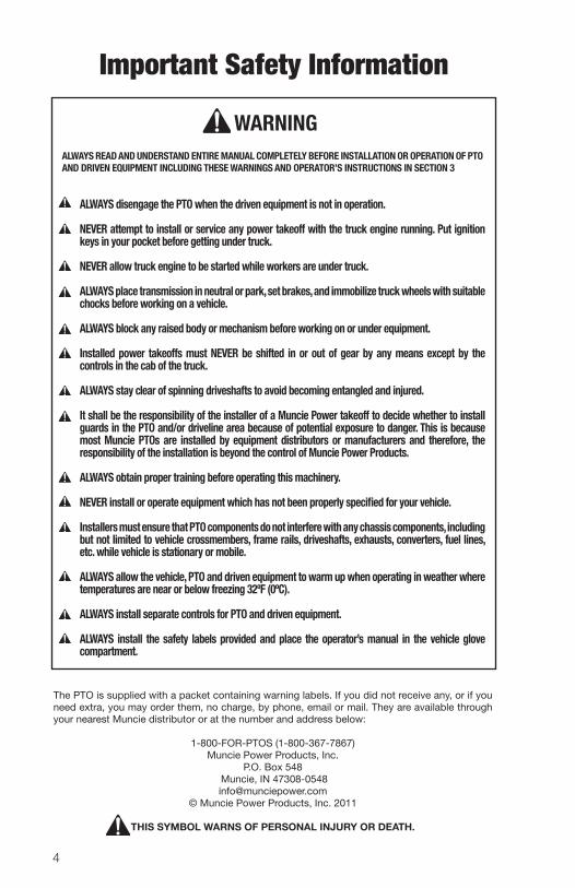
ALWAYS READ AND UNDERSTAND ENTIRE MANUAL COMPLETELY BEFORE INSTALLATION OR OPERATION OF PTO AND DRIVEN EQUIPMENT INCLUDING THESE WARNINGS AND OPERATOR’S INSTRUCTIONS IN SECTION 3
WARNING
Important Safety Information
5
SECTION 1- PTO INSTALLATION ALL INSTALLERS MUST READ THE FOLLOWING
PTO AND ACTIVATION KIT INSTALLATION INSTRUCTIONS
Always wear safety glasses. Read entire manual before starting installation.
IMPORTANT: Disconnect vehicle battery prior to installing electrical and electric/hydraulic activation kits.
A. Vehicle manufacturers may have specific locations for accessing electrical power and activating hydraulics. The body builder manual or company repre sentative for the vehicle chassis should be contacted prior to installing electri cal or hydraulic systems. B. Route wires and activation lines away from rotating and high temperature com ponents. Use appropriate looms and bulk head pass -thru’s wherever possible to avoid rubbing through insulation or tubing and causing an electrical short or oil leak.
C. Follow all Federal Motor Vehicle Safety Standards (FMVSS) for your vehicle. D. Where electrical grounds are indicated, be sure that they are good grounds, with straight paths to the vehicle battery ground. (Many vehicle cabs are insu lated from the vehicle frame and a weak ground is a very common cause for malfunctions).
E. When installing hydraulic components, be certain to follow common installa tion and testing procedures. If you are not familiar with acceptable installation procedures request instructions and guidance from the hydraulic equipment supplier. F. Caution should be taken by installer with any PTO installation to insure compo nents do not interfere with any chassis component during installation or when vehicle is operated.
G. Cold weather start conditions require that the transmission be started and warmed prior to engaging PTO and using equipment. Hydraulic pumps should be run at idle and under no load conditions to allow oil to warm before activat ing hydraulic system.
IMPORTANT INFORMATION: There is valuable information contained in the Ford “Super Duty F-Series Body
Builders Layout Book”. You can obtain a copy of this book by faxing your request to “Body Builder Coordinator” at 1 -734 -414 -2971. Include your street address and
desired vehicle and model year. It can also be found on the Ford website at http://www.fleet.ford.com/truckbbas/
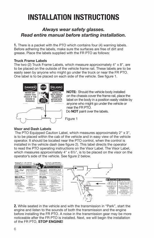
1. There is a packet with the PTO which contains four (4) warning labels. Before adhering the labels, make sure the surfaces are free of dirt and grease. Place the labels supplied with the FR PTO as follows:
Truck Frame LabelsThe two (2) Truck Frame Labels, which measure approximately 4" x 8", are to be placed on the outside of the vehicle frame rail. These labels are to be easily seen by any one who might go under the truck or near the FR PTO. One label is to be placed on each side of the vehicle. See figure 1.
NOTE: Should the vehicle body installed on the chassis cover the frame rail, place the label on the body in a position easily visible by anyone who might go under the vehicle or near the FR PTO. Do NOT paint over the labels.
Visor and Dash Labels The PTO Equipped Caution Label, which measures approximately 2" x 3", is to be placed within the cab of the vehicle and in easy view of the vehicle operator. It should be located near the PTO control, when the control is installed in the vehicle dash (see figure 2). This label directs the operator to read the PTO operating instructions on the Visor Label. The Visor Label, which measures approximately 4" x 6½", is to be placed on the visor on the operator’s side of the vehicle. See figure 2 below.
2. While seated in the vehicle and with the trans mission in “Park”, start the engine and lis ten to the sounds of both the transmission and the engine before installing the FR PTO. A noise in the transmission gear may be more noticeable after the FR PTO is installed. Next, we will begin the installation of the FR PTO, STOP ENGINE!
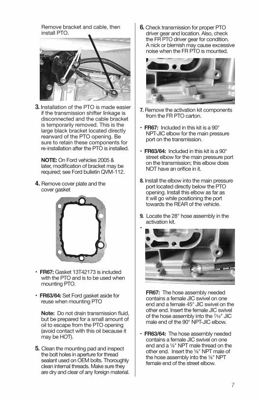
6. Check transmission for proper PTO driver gear and location. Also, check the FR PTO driver gear for condition. A nick or blemish may cause excessive noise when the FR PTO is mounted.
7. Remove the activation kit components from the FR PTO carton.
• FR67: Included in this kit is a 90° NPT-JIC elbow for the main pressure port on the transmission.
• FR63/64: Included in this kit is a 90° street elbow for the main pressure port on the transmission; this elbow does NOT have an orifice in it.
8. Install the elbow into the main pressure port located directly below the PTO opening. Install this elbow as far as it will go while positioning the port towards the REAR of the vehicle.
9. Locate the 28" hose assembly in the activation kit.
•
FR67: The hose assembly needed contains a female JIC swivel on one end and a female 45° JIC swivel on the other end. Insert the female JIC swivel of the hose assembly into the 7∕16" JIC male end of the 90° NPT-JIC elbow.
• FR63/64: The hose assembly needed contains a female JIC swivel on one end and a ⅛" NPT male thread on the other end. Insert the ⅛" NPT male of the hose assembly into the ⅛" NPT female end of the street elbow.
3. Installation of the PTO is made easier if the transmission shifter linkage is disconnected and the cable bracket is tem porarily removed. This is the large black bracket located directly rearward of the PTO opening. Be sure to retain these components for re -installation after the PTO is installed.
NOTE: On Ford vehicles 2005 & later, modification of bracket may be required; see Ford bulletin QVM-112.
4. Remove cover plate and the cover gasket
• FR67: Gasket 13T42173 is included with the PTO and is to be used when mounting PTO.
• FR63/64: Set Ford gasket aside for reuse when mounting PTO
Note: Do not drain transmission fluid, but be pre pared for a small amount of oil to escape from the PTO opening (avoid contact with this oil because it may be HOT).
5. Clean the mounting pad and inspect the bolt holes in aperture for thread sealant used on OEM bolts. Thoroughly clean internal threads. Make sure they are dry and clear of any foreign material.
Remove bracket and cable, then install PTO.
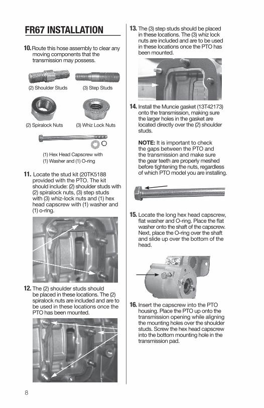
13. The (3) step studs should be placed in these locations. The (3) whiz lock nuts are included and are to be used in these locations once the PTO has been mounted.
14. Install the Muncie gasket (13T42173) onto the transmission, making sure the larger holes in the gasket are located directly over the (2) shoulder studs.
NOTE: It is important to check the gaps between the PTO and the transmission and make sure the gear teeth are properly meshed before tightening the nuts, regardless of which PTO model you are installing.
15. Locate the long hex head capscrew, flat washer and O-ring. Place the flat washer onto the shaft of the capscrew. Next, place the O-ring over the shaft and slide up over the bottom of the head.
16. Insert the capscrew into the PTO housing. Place the PTO up onto the transmission opening while aligning the mounting holes over the shoulder studs. Screw the hex head capscrew into the bottom mounting hole in the transmission pad.
10. Route this hose assembly to clear any moving components that the transmission may possess.
11. Locate the stud kit (20TK5188 provided with the PTO. The kit should include: (2) shoulder studs with (2) spiralock nuts, (3) step studs with (3) whiz-lock nuts and (1) hex head capscrew with (1) washer and (1) o-ring.
12. The (2) shoulder studs should be placed in these locations. The (2) spiralock nuts are included and are to be used in these locations once the PTO has been mounted.
8
FR67 INSTALLATION
(1) Hex Head Capscrew with (1) Washer and (1) O-ring
(2) Shoulder Studs
(2) Spiralock Nuts
(3) Step Studs
(3) Whiz Lock Nuts
9
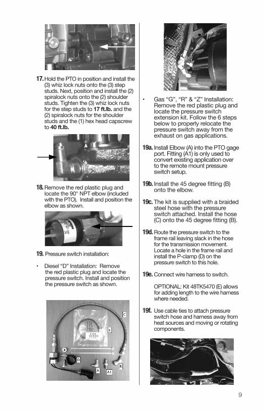
• Gas “G”, “R” & “Z” Installation: Remove the red plastic plug and locate the pressure switch extension kit. Follow the 6 steps below to properly relocate the pressure switch away from the exhaust on gas applications.
19a. Install Elbow (A) into the PTO gage port. Fitting (A1) is only used to convert existing application over to the remote mount pressure switch setup.
19b. Install the 45 degree fitting (B) onto the elbow.
19c. The kit is supplied with a braided steel hose with the pressure switch attached. Install the hose (C) onto the 45 degree fitting (B). 19d. Route the pressure switch to the frame rail leaving slack in the hose for the transmission movement. Locate a hole in the frame rail and install the P-clamp (D) on the pressure switch to this hole.
19e. Connect wire harness to switch.
OPTIONAL: Kit 48TK5470 (E) allows for adding length to the wire harness where needed.
19f. Use cable ties to attach pressure switch hose and harness away from heat sources and moving or rotating components.
17. Hold the PTO in position and install the (3) whiz lock nuts onto the (3) step studs. Next, position and install the (2) spiralock nuts onto the (2) shoulder studs. Tighten the (3) whiz lock nuts for the step studs to 17 ft.lb. and the (2) spiralock nuts for the shoulder studs and the (1) hex head capscrew to 40 ft.lb.
18. Remove the red plastic plug and locate the 90° NPT elbow (included with the PTO). Install and position the elbow as shown.
19. Pressure switch installation:
• Diesel “D” Installation: Remove the red plastic plug and locate the pressure switch. Install and position the pressure switch as shown.
10
20. Install the female 45° JIC swivel end onto the male JIC swivel end of the 90° NPT-JIC elbow.
NOTE: For steps 21-23, the picture shows the old 28" hose assembly. This hose has been changed to a JIC-45° JIC swivel.
21. Use cable ties to route the hose away from the exhaust and away from any components. Route the wiring harness from the vehicle front passenger compartment to the solenoid valve.
22. Make the connections to the pressure switch and the solenoid valve. Refer to page 29 for more details.
NOTE: The solenoid and pressure switch connectors are both Metri-Pack.
Go to step #32 on page 14 to complete the FR67 installation
FR64/67 THRU-BOLT INSTALLATION
Detail A
Install O-ring, followed by washer, BEFORE placingthe hex head capscrew into the mounting hole
11
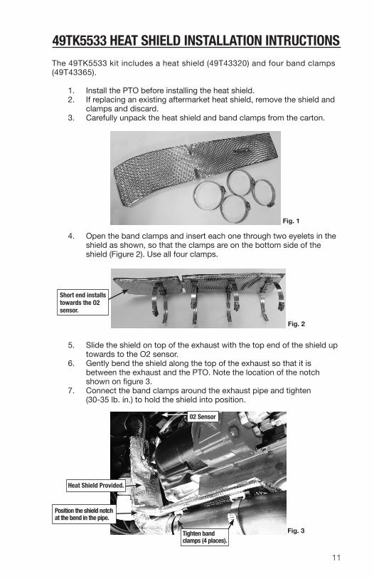
49TK5533 HEAT SHIELD INSTALLATION INTRUCTIONSThe 49TK5533 kit includes a heat shield (49T43320) and four band clamps (49T43365).
1. Install the PTO before installing the heat shield. 2. If replacing an existing aftermarket heat shield, remove the shield and clamps and discard. 3. Carefully unpack the heat shield and band clamps from the carton.
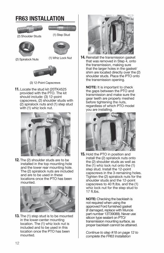
4. Open the band clamps and insert each one through two eyelets in the shield as shown, so that the clamps are on the bottom side of the shield (Figure 2). Use all four clamps.
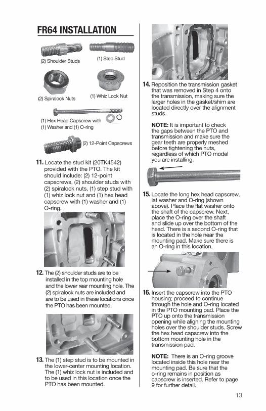
5. Slide the shield on top of the exhaust with the top end of the shield up towards to the O2 sensor. 6. Gently bend the shield along the top of the exhaust so that it is between the exhaust and the PTO. Note the location of the notch shown on figure 3. 7. Connect the band clamps around the exhaust pipe and tighten (30-35 lb. in.) to hold the shield into position.
Fig. 1
Fig. 3
Fig. 2
Short end installs towards the O2 sensor.
Position the shield notch at the bend in the pipe.
Heat Shield Provided.
Tighten band clamps (4 places).
02 Sensor
12
14. Reinstall the transmission gasket that was removed in Step 4, onto the transmission, making sure that the larger holes in the gasket/ shim are located directly over the (2) shoulder studs. Place the PTO onto the transmission opening.
NOTE: It is important to check the gaps between the PTO and transmission and make sure the gear teeth are properly meshed before tightening the nuts, regardless of which PTO model you are installing.
15. Hold the PTO in position and install the (2) spiralock nuts onto the (2) shoulder studs as well as the (1) whiz lock nut onto the (1) step stud. Install the 12-point capscrews in the 3-remaining holes. Tighten the (2) spiralock nuts for the shoulder studs and the 12-point capscrews to 40 ft.lbs. and the (1) whiz lock nut for the step stud to 17 ft.lbs.
NOTE: Checking the backlash is not required when using the approved Ford furnished gasket (if damaged, replace with Muncie part number 13T39089). Never use silicon type sealant on PTO/ transmission mounting surface, as proper backlash cannot be attained.
Continue to step #18 on page 12 to complete the FR63 Installation
11. Locate the stud kit (20TK4525 provided with the PTO. The kit should include: (3) 12-point capscrews, (2) shoulder studs with (2) spiralock nuts and (1) step stud with (1) whiz lock nut.
12. The (2) shoulder studs are to be installed in the top mounting hole and the lower rear mounting hole. The (2) spiralock nuts are included and are to be used in these locations once the PTO has been mounted.
13. The (1) step stud is to be mounted in the lower-center mounting location. The (1) whiz lock nut is included and to be used in this location once the PTO has been mounted.
FR63 INSTALLATION
(2) Shoulder Studs
(2) Spiralock Nuts
(1) Step Stud
(1) Whiz Lock Nut
(3) 12-Point Capscrews
13
14. Reposition the transmission gasket that was removed in Step 4 onto the transmission, making sure the larger holes in the gasket/shim are located directly over the alignment studs. NOTE: It is important to check the gaps between the PTO and transmission and make sure the gear teeth are properly meshed before tightening the nuts, regardless of which PTO model you are installing.
15. Locate the long hex head capscrew, lat washer and O-ring (shown above). Place the flat washer onto the shaft of the capscrew. Next, place the O-ring over the shaft and slide up over the bottom of the head. There is a second O-ring that is located in the hole near the mounting pad. Make sure there is an O-ring in this location.
16. Insert the capscrew into the PTO housing; proceed to continue through the hole and O-ring located in the PTO mounting pad. Place the PTO up onto the transmission opening while aligning the mounting holes over the shoulder studs. Screw the hex head capscrew into the bottom mounting hole in the transmission pad.
NOTE: There is an O-ring groove located inside this hole near the mounting pad. Be sure that the o-ring remains in position as capscrew is inserted. Refer to page 9 for further detail.
11. Locate the stud kit (20TK4542) provided with the PTO. The kit should include: (2) 12-point capscrews, (2) shoulder studs with (2) spiralock nuts, (1) step stud with (1) whiz lock nut and (1) hex head capscrew with (1) washer and (1) O-ring.
12. The (2) shoulder studs are to be installed in the top mounting hole and the lower rear mounting hole. The (2) spiralock nuts are included and are to be used in these locations once the PTO has been mounted.
13. The (1) step stud is to be mounted in the lower-center mounting location. The (1) whiz lock nut is included and to be used in this location once the PTO has been mounted.
(1) Hex Head Capscrew with (1) Washer and (1) O-ring
(2) Shoulder Studs
(2) Spiralock Nuts
(1) Step Stud
(1) Whiz Lock Nut
(2) 12-Point Capscrews
FR64 INSTALLATION
14
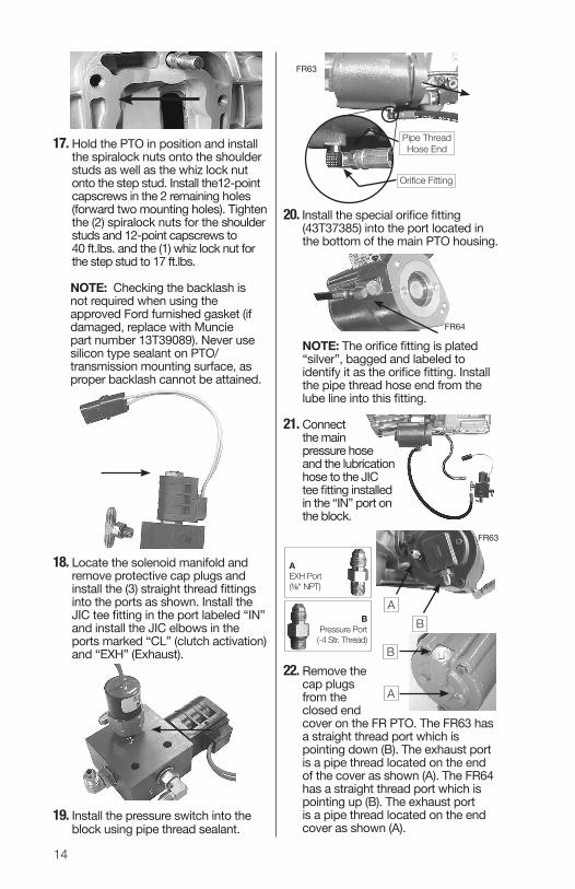
20. Install the special orifice fitting (43T37385) into the port located in the bottom of the main PTO housing.
NOTE: The orifice fitting is plated “silver”, bagged and labeled to identify it as the orifice fitting. Install the pipe thread hose end from the lube line into this fitting.
21. Connect the main pressure hose and the lubrication hose to the JIC tee fitting installed in the “IN” port on the block.
22. Remove the cap plugs from the closed end cover on the FR PTO. The FR63 has a straight thread port which is pointing down (B). The exhaust port is a pipe thread located on the end of the cover as shown (A). The FR64 has a straight thread port which is pointing up (B). The exhaust port is a pipe thread located on the end cover as shown (A).
17. Hold the PTO in position and install the spiralock nuts onto the shoulder studs as well as the whiz lock nut onto the step stud. Install the12-point capscrews in the 2 remaining holes (forward two mounting holes). Tighten the (2) spiralock nuts for the shoulder studs and 12-point capscrews to 40 ft.lbs. and the (1) whiz lock nut for the step stud to 17 ft.lbs.
NOTE: Checking the backlash is not required when using the approved Ford furnished gasket (if damaged, replace with Muncie part number 13T39089). Never use silicon type sealant on PTO/ transmission mounting surface, as proper backlash cannot be attained.
18. Locate the solenoid manifold and remove protective cap plugs and install the (3) straight thread fittings into the ports as shown. Install the JIC tee fitting in the port labeled “IN” and install the JIC elbows in the ports marked “CL” (clutch activation) and “EXH” (Exhaust).
19. Install the pressure switch into the block using pipe thread sealant.
Pipe ThreadHose End
Orifice Fitting
FR63
FR64
B A
FR63
BPressure Port
(-4 Str. Thread)
AEXH Port(⅛" NPT)
B
A
15
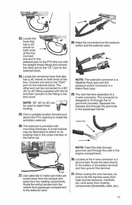
23. Locate the hose that has a JIC swivel on both ends of the line. Connect one end to the pressure port on the PTO (the one with the straight thread fitting) and connect the other end to the “CL” port on the solenoid block.
24. Locate the remaining hose that also has a JIC swivel on both ends of the line. Connect one end to the “EXH” port on the solenoid block. The other end can be connected to a 90° JIC to JIC fitting supplied with the kit and then connect to the fitting in the end cover.
NOTE: 90° JIC to JIC can be used to ease hose routing. 25. Find a suitable location forward and above the PTO opening to install the activation solenoid. 26. The solenoid is provided with mounting hardware. A small bracket may be fabricated to attach to an existing hole in the cross member or the frame rail.
27. Use cable ties to make sure holes are routed away from the exhaust and away from any rotating components. Route the wiring harness from the vehicle front passenger compartment to the solenoid valve.
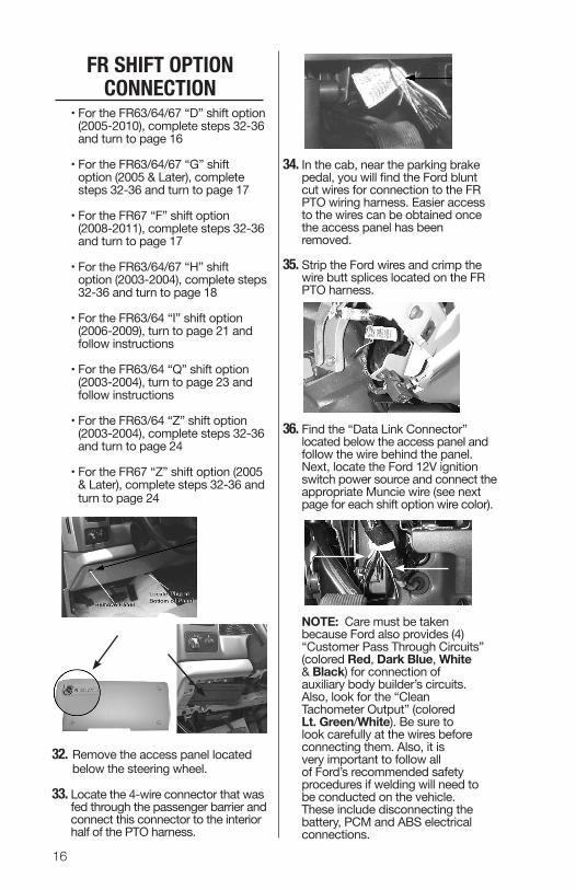
28. Make the connections to the pressure switch and the solenoid valve.
NOTE: The solenoid connector is a Weather-Pack type and the pressure switch connector is a Metri-Pack type.
29. The wire harness separates at a 4-wire connector. The connector is designed to fit through the ⅝" grommet provided. Separate the harness end through the grommet in the passenger barrier.
NOTE: Feed this side through grommet and through the wall in the engine compartment.
30. Located at the 4-wire connector is a ground lead. Route this lead directly to the battery or the battery terminal and then ground this terminal.
31. When routing the wire harness, be sure to tie the harness away from heat sources (exhaust, manifold, etc.) and away from rotating components (driveshafts, belts, etc.).
Inside Cab
16
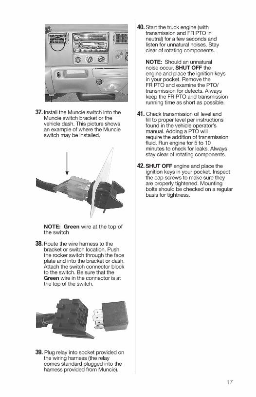
34. In the cab, near the parking brake pedal, you will find the Ford blunt cut wires for connection to the FR PTO wiring harness. Easier access to the wires can be obtained once the access panel has been removed.
35. Strip the Ford wires and crimp the wire butt splices located on the FR PTO harness.
36. Find the “Data Link Connector” located below the access panel and follow the wire behind the panel. Next, locate the Ford 12V ignition switch power source and connect the appropriate Muncie wire (see next page for each shift option wire color).
NOTE: Care must be taken because Ford also provides (4) “Customer Pass Through Circuits” (colored Red, Dark Blue, White & Black) for connection of auxiliary body builder’s circuits. Also, look for the “Clean Tachometer Output” (colored Lt. Green/White). Be sure to look carefully at the wires before connecting them. Also, it is very important to follow all of Ford’s recommended safety procedures if welding will need to be conducted on the vehicle. These include disconnecting the battery, PCM and ABS electrical connections.
• For the FR63/64/67 “D” shift option (2005-2010), complete steps 32-36 and turn to page 16
• For the FR63/64/67 “G” shift option (2005 & Later), complete steps 32-36 and turn to page 17
• For the FR67 “F” shift option (2008-2011), complete steps 32-36 and turn to page 17 • For the FR63/64/67 “H” shift option (2003-2004), complete steps 32-36 and turn to page 18
• For the FR63/64 “I” shift option (2006-2009), turn to page 21 and follow instructions
• For the FR63/64 “Q” shift option (2003-2004), turn to page 23 and follow instructions
• For the FR63/64 “Z” shift option (2003-2004), complete steps 32-36 and turn to page 24
• For the FR67 “Z” shift option (2005 & Later), complete steps 32-36 and turn to page 24
32. Remove the access panel located below the steering wheel.
33. Locate the 4-wire connector that was fed through the passenger barrier and connect this connector to the interior half of the PTO harness.
FR SHIFT OPTION CONNECTION
17
37. Install the Muncie switch into the Muncie switch bracket or the vehicle dash. This picture shows an example of where the Muncie switch may be installed.
NOTE: Green wire at the top of the switch
38. Route the wire harness to the bracket or switch location. Push the rocker switch through the face plate and into the bracket or dash. Attach the switch connector block to the switch. Be sure that the Green wire in the connector is at the top of the switch.
39. Plug relay into socket provided on the wiring harness (the relay comes standard plugged into the harness provided from Muncie).
40. Start the truck engine (with transmission and FR PTO in neutral) for a few seconds and listen for unnatural noises. Stay clear of rotating components.
NOTE: Should an unnatural noise occur, SHUT OFF the engine and place the ignition keys in your pocket. Remove the FR PTO and examine the PTO/ transmission for defects. Always keep the FR PTO and transmission running time as short as possible. 41. Check transmission oil level and fill to proper level per instructions found in the vehicle operator’s manual. Adding a PTO will require the addition of transmission fluid. Run engine for 5 to 10 minutes to check for leaks. Always stay clear of rotating components.
42. SHUT OFF engine and place the ignition keys in your pocket. Inspect the cap screws to make sure they are properly tightened. Mounting bolts should be checked on a regular basis for tightness.
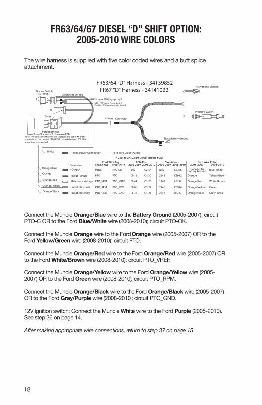
The wire harness is supplied with five color coded wires and a butt splice attachment.
Connect the Muncie Orange/Blue wire to the Battery Ground (2005-2007); circuit PTO-C OR to the Ford Blue/White wire (2008-2010); circuit PTO-OK. Connect the Muncie Orange wire to the Ford Orange wire (2005-2007) OR to the Ford Yellow/Green wire (2008-2010); circuit PTO.
Connect the Muncie Orange/Red wire to the Ford Orange/Red wire (2005-2007) OR to the Ford White/Brown wire (2008-2010); circuit PTO_VREF.
Connect the Muncie Orange/Yellow wire to the Ford Orange/Yellow wire (2005-2007) OR to the Ford Green wire (2008-2010); circuit PTO_RPM.
Connect the Muncie Orange/Black wire to the Ford Orange/Black wire (2005-2007) OR to the Ford Gray/Purple wire (2008-2010); circuit PTO_GND.
12V ignition switch: Connect the Muncie White wire to the Ford Purple (2005-2010). See step 36 on page 14.
After making appropriate wire connections, return to step 37 on page 15
Turn Clockwise To Increase RPMNote: The adjustment screw will increase the set RPM of the engine from the pre-set 1200 RPM. Speeds below 1200 RPM are not recommended.
4-Wire Connector
FR67 "D" Harness - 34T41022Green Wire On Top
Potentiometer
FR63/64 "D" Harness - 34T39852
19
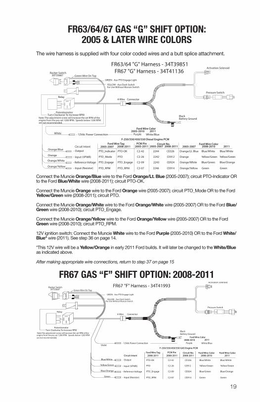
FR63/64/67 GAS “G” SHIFT OPTION: 2005 & LATER WIRE COLORS
The wire harness is supplied with four color coded wires and a butt splice attachment.
Connect the Muncie Orange/Blue wire to the Ford Orange/Lt. Blue (2005-2007); circuit PTO-Indicator OR to the Ford Blue/White wire (2008-2011); circuit PTO-OK.
Connect the Muncie Orange wire to the Ford Orange wire (2005-2007); circuit PTO_Mode OR to the Ford Yellow/Green wire (2008-2011); circuit PTO.
Connect the Muncie Orange/White wire to the Ford Orange/White wire (2005-2007) OR to the Ford Blue/Green wire (2008-2010); circuit PTO_Engage.
Connect the Muncie Orange/Yellow wire to the Ford Orange/Yellow wire (2005-2007) OR to the Ford Green wire (2008-2010); circuit PTO_RPM.
12V ignition switch: Connect the Muncie White wire to the Ford Purple (2005-2010) OR to the Ford White/Blue* wire (2011). See step 36 on page 14.
*This 12V wire will be a Yellow/Orange in early 2011 Ford builds. It will later be changed to the White/Blue as indicated above.
After making appropriate wire connections, return to step 37 on page 15
FR67 GAS “F” SHIFT OPTION: 2008-2011
AB
TAG
AB
BA
GREEN - Aux PTO Engage Light
YELLOW - Aux Dash Switch
Rocker Switch30T35687
For Use Without Muncie Switch
Relay
Black Battery Ground
White
Orange/Blue
Orange
Orange/White
Orange/Yellow
- 12Vdc Power Connection
- Output
- Input (VPWR)
- Reference Voltage
- Input (Resistor)
Pressure Switch
Activation Solenoid
F-250/350/450/550 Diesel Engine PCM
Circuit Intent 2005-2007
PTO-OK
PTO_Mode
PTO_Engage
PTO_RPM
2005-2007
C2-42
C2-26
C2-09
C2-07
4-Wire Connector
FR67 "G" Harness - 34T41136Green Wire On Top
Ford Wire Color
2005-2011
2242
2246
2244
2243
2005-2007 2008-2010Ford Wire Color
Orange/Lt. Blue
Orange/White
Orange/Yellow
Blue/White
Yellow/Green
Green
Orange
2008-2011
PTO_Indicator
Ford Wire Tag
PTO
PTO_Engage
PTO_RPM
Blue/Green
2008-2011Circuit No.PCM Pin
The adjustment screw will increase the set RPM of the Turn Clockwise To Increase RPM
Note:engine from the pre-set 1200 RPM. Speeds below 1200 RPM are not recommended.
Potentiometer
FR63/64 "G" Harness - 34T39851
CE326
CE912
CE924
CE914
2011
Blue/White
Yellow/Green
Green
Blue/Orange
2005-2010 2011Purple White/Blue
AB
TAG
AB
BA
GREEN - Aux PTO Engage Light
YELLOW - Aux Dash Switch
Rocker Switch30T35687
For Use Without Muncie Switch
Relay
Black Battery Ground
Pressure Switch
Activation Solenoid
4-Wire Connector
FR67 "F" Harness - 34T41993Green Wire On Top
Turn Clockwise To Increase RPMNote: The adjustment screw will increase the set RPM of the engine from the pre-set 1200 RPM. Speeds below 1200 RPM are not recommended.
Potentiometer
- 12Vdc Power Connection
- Output
- Input (VPWR)
- Reference Voltage
- Input (Resistor)
F-250/350/450/550 GAS Engine PCM
Circuit Intent
PTO-OK C2-42
C2-26
C2-09
C2-07
Ford Wire Color
Ford Wire ColorFord Wire Tag
PTO
PTO_Engage
PTO_RPM
Circuit No.PCM Pin
CE326
CE912
CE924
CE914
Blue/White
Yellow/Green
Green
Blue/Green
2011White/Blue
Blue/White
Yellow/Green
Green
Blue/Orange
Violet
2008-2011 2008-2011 2008-2011 2008-2010Ford Wire Color
Blue/White
Yellow/Green
Green
Blue/Orange
2011
2008-2010Purple
20
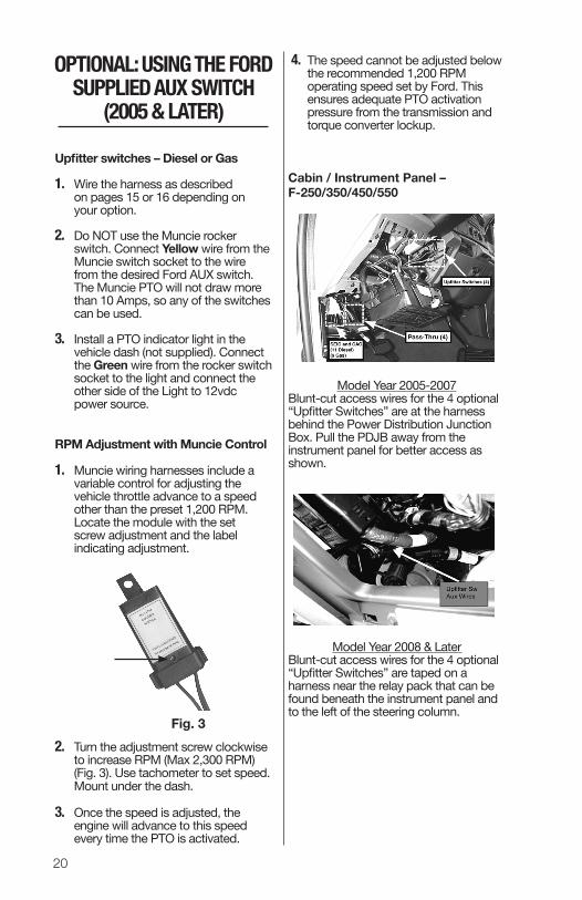
4. The speed cannot be adjusted below the recommended 1,200 RPM operating speed set by Ford. This ensures adequate PTO activation pressure from the transmission and torque converter lock up.
Cabin / Instrument Panel – F-250/350/450/550
Model Year 2005-2007Blunt-cut access wires for the 4 optional “Upfitter Switches” are at the harness behind the Power Distribution Junction Box. Pull the PDJB away from the instrument panel for better access as shown.
Model Year 2008 & LaterBlunt-cut access wires for the 4 optional “Upfitter Switches” are taped on a harness near the relay pack that can be found beneath the instrument panel and to the left of the steering column.
Upfitter switches – Diesel or Gas
1. Wire the harness as described on pages 15 or 16 depending on your option.
2. Do NOT use the Muncie rocker switch. Connect Yellow wire from the Muncie switch socket to the wire from the desired Ford AUX switch. The Muncie PTO will not draw more than 10 Amps, so any of the switches can be used.
3. Install a PTO indicator light in the vehicle dash (not supplied). Connect the Green wire from the rocker switch socket to the light and connect the other side of the Light to 12vdc power source.
RPM Adjustment with Muncie Control
1. Muncie wiring harnesses include a variable control for adjusting the vehicle throttle advance to a speed other than the preset 1,200 RPM. Locate the module with the set screw adjustment and the label indicating adjustment.
2. Turn the adjustment screw clockwise to increase RPM (Max 2,300 RPM) (Fig. 3). Use tachometer to set speed. Mount under the dash.
3. Once the speed is adjusted, the engine will advance to this speed every time the PTO is activated.
Fig. 3
OPTIONAL: USING THE FORD SUPPLIED AUX SWITCH
(2005 & LATER)
21
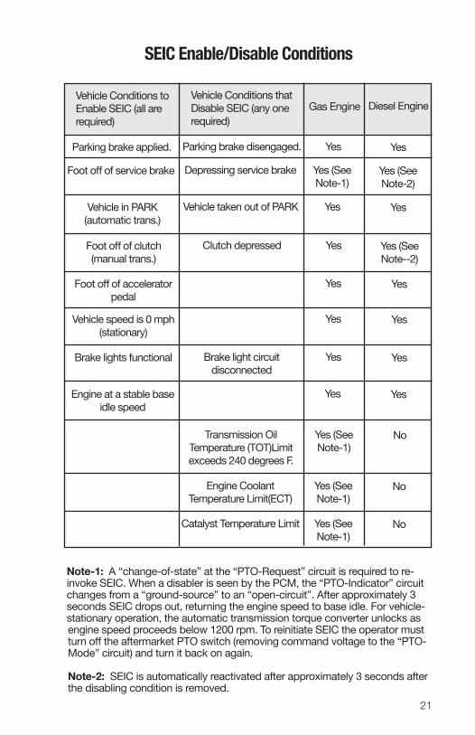
Note -1: A “change -of -state” at the “PTO -Request” circuit is required to re-invoke SEIC. When a disabler is seen by the PCM, the “PTO- Indicator” circuit changes from a “ground- source” to an “open- circuit”. After approxi mately 3 seconds SEIC drops out, returning the engine speed to base idle. For vehicle-stationary operation, the automatic transmission torque converter unlocks as engine speed proceeds below 1200 rpm. To re initiate SEIC the operator must turn off the aftermarket PTO switch (removing command voltage to the “PTO- Mode” circuit) and turn it back on again.
Note -2: SEIC is automatically re activated after approximately 3 seconds after the disabling condition is removed.
SEIC Enable/Disable Conditions
Vehicle Conditions to Enable SEIC (all are required)
Vehicle Conditions that Disable SEIC (any one required)
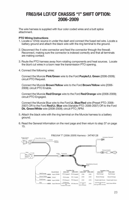
The wire harness is supplied with four color coded wires and a butt splice attachment.
PTO Wiring Instructions1. Locate a 12Vdc source in under the dash and connect the fused red wire. Locate a
battery ground and attach the black wire with the ring terminal to the ground.
2. Disconnect the 4-wire connector and feed the connector through the firewall. Reconnect, making sure the connector is indexed correctly and that all terminals are making contact.
3. Route the PTO harness away from rotating components and heat sources. Locate the blunt cut wires in a loom near the transmission PTO opening.
4. Connect the following wires:
Connect the Muncie Pink/Green wire to the Ford Purple/Lt. Green (2006-2009); circuit PTO Request.
Connect the Muncie Brown/Yellow wire to the Ford Brown/Yellow wire (2006-
2009); circuit PTO Enable.
Connect the Muncie Red/Orange wire to the Ford Red/Orange wire (2006-2009); circuit PTO Engaged.
Connect the Muncie Blue wire to the Ford Lt. Blue/Red wire (Preset PTO: 2006-2007) OR to the Ford Red/Lt. Blue wire (Variable PTO: 2006-2007) OR to the Ford Dk. Green/White wire (2008-2009); circuit PTO_RPM.
5. Attach the black wire with the ring terminal on the Muncie harness to a battery ground.
6. Read the General Information on the next page and then return to step 37 on page 15.
AB
TAG
AB
BA
Rocker Switch30T37752
Relay
Black Battery Ground
Red/Orange
Brown/Yellow
Pink/Green
Blue
- Input (VPWR)
- Output
- Input (VPWR)
- Input (Resistor)
Pressure Switch
Activation Solenoid
Circuit Intent 2006-2007
PTO Engaged
PTO Enable
2006-2007
4-Wire Connector
Green Wire On Top
2334
2231 (Preset)
2336
2335
2006-2007 2008-2009Ford Wire Color
Red/Orange
Purple/Light Green
Brown/Orange
2008-2009
PTO Engaged
Ford Wire Tag
PTO Enable
PTO Request
PTO Resume
2008-2009Circuit No.
FR63/64 "I" (2006-2009) Harness - 34T40128
1924
+12V DC
Ground
ECM RemotePreset PTO Enable
Variable PTO EnableOR
PTO Request
2232 (Variable)OR
2334
2336
2335
Red/Orange
Purple/Light Green
Dark Green/White
Brown/Orange
Light Blue/Red (Preset)
Red/Light Blue (Variable)OR
Battery
24
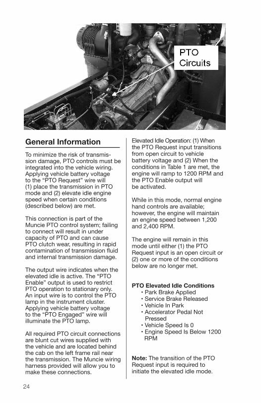
Elevated Idle Operation: (1) When the PTO Request input transitions from open circuit to vehicle battery voltage and (2) When the conditions in Table 1 are met, the engine will ramp to 1200 RPM and the PTO Enable output will be activated.
While in this mode, normal engine hand controls are available; howev er, the engine will maintain an engine speed between 1,200 and 2,400 RPM.
The engine will remain in this mode until either (1) the PTO Request input is an open circuit or (2) one or more of the con ditions below are no longer met.
PTO Elevated Idle Conditions • Park Brake Applied • Service Brake Released • Vehicle In Park • Accelerator Pedal Not Pressed • Vehicle Speed Is 0 • Engine Speed Is Below 1200 RPM
Note: The transition of the PTO Request input is required to initiate the elevated idle mode.
General InformationTo minimize the risk of transmis-sion damage, PTO controls must be integrated into the vehicle wiring. Applying vehicle battery voltage to the “PTO Request” wire will (1) place the transmission in PTO mode and (2) elevate idle engine speed when certain conditions (described below) are met.
This connection is part of the Muncie PTO control system; failing to connect will result in under capacity of PTO and can cause PTO clutch wear, resulting in rapid contamination of transmission fluid and internal transmission damage.
The output wire indicates when the elevated idle is active. The “PTO Enable” output is used to restrict PTO operation to stationary only. An input wire is to control the PTO lamp in the instrument cluster. Applying vehicle battery voltage to the “PTO Engaged” wire will illuminate the PTO lamp.
All required PTO circuit connec tions are blunt cut wires supplied with the vehicle and are located behind the cab on the left frame rail near the transmission. The Muncie wiring harness provided will allow you to make these con nections.
25
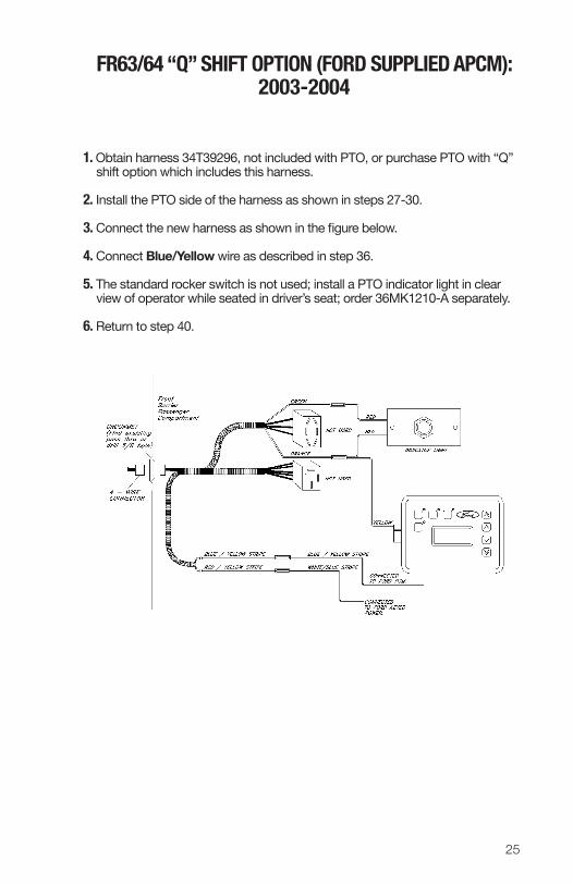
1. Obtain harness 34T39296, not included with PTO, or purchase PTO with “Q” shift option which includes this harness.
2. Install the PTO side of the harness as shown in steps 27-30.
3. Connect the new harness as shown in the figure below.
4. Connect Blue/Yellow wire as described in step 36. 5. The standard rocker switch is not used; install a PTO indicator light in clear
view of operator while seated in driver’s seat; order 36MK1210-A separately.
Requires the purchase of the “Z” option on the original PTO model or kit 43TK4524 and 34T39185
1. The 2-position switch option does not change the way the harness or the rocker switch are installed. In this “Z” option, the relay (37T37621) is not used.
2. When installing the “Z” option, the wire harness connector has a Green wire which should be positioned at the top. The Green wire will line up with the red light on the rocker switch (30T35687).
3. Installation does not require any modification to the existing wiring harness.
4. Return to step 32, but skip over step 39 because the relay is not used.
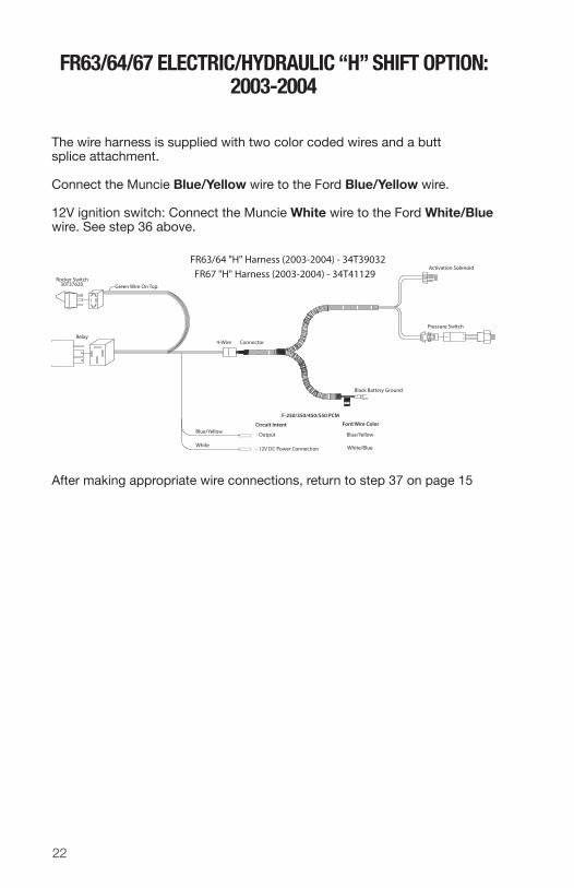
The wire harness is supplied with two color coded wires and a butt splice attachment.
Connect the Muncie Blue/Yellow wire to the Ford Orange/Lt. Blue (2005-2007) OR to the Ford Yellow/Green (2008 -2011) wire.
12V ignition switch: Connect the Muncie White wire to the Ford White/Blue (2005-2007) wire OR to the Ford Purple (2008-2010) OR to the Ford White/Blue (2011). See step 36 on page 14.
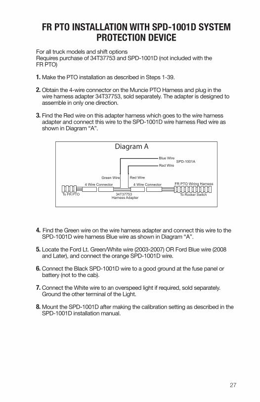
For all truck models and shift optionsRequires purchase of 34T37753 and SPD- 1001D (not included with the FR PTO)
1. Make the PTO installation as described in Steps 1-39.
2. Obtain the 4-wire con nector on the Muncie PTO Harness and plug in the wire harness adapter 34T37753, sold separately. The adapter is designed to assemble in only one direction.
3. Find the Red wire on this adapter harness which goes to the wire harness adapter and connect this wire to the SPD-1001D wire harness Red wire as shown in Diagram “A”.
4. Find the Green wire on the wire harness adapter and connect this wire to the SPD-1001D wire harness Blue wire as shown in Diagram “A”.
5. Locate the Ford Lt. Green/White wire (2003-2007) OR Ford Blue wire (2008 and Later), and connect the orange SPD-1001D wire.
6. Connect the Black SPD-1001D wire to a good ground at the fuse panel or battery (not to the cab).
7. Connect the White wire to an overspeed light if required, sold sepa rately. Ground the other terminal of the Light.
8. Mount the SPD-1001D after making the calibration setting as described in the SPD-1001D installation manual.
FR PTO INSTALLATION WITH SPD-1001D SYSTEM PROTECTION DEVICE
4 Wire Connector FR PTO Wiring Harness
Blue Wire
Red Wire
To FR PTO To Rocker Switch
4 Wire Connector
34T37753Harness Adapter
Red WireGreen Wire
SPD-1001A
Diagram A
28
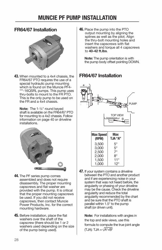
FR64/67 Installation
43. When mounted to a 4x4 chassis, the FR64/67 PTO requires the use of a special hydraulic pump mounting which is found on the Muncie PF4- ***-16QSRL pumps. This pump uses thru-bolts to mount to the FR PTO. This is the only pump to be used on the FR and a 4x4 chassis.
Note: The 1-¼" round keyed shaft is available on the FR64/67 PTO for mounting to a 4x2 chassis. Follow information on page 40 or driveline installations.
44. The PF series pump comes assembled and does not require disassembly. The proper mounting capscrews and flat washer are provided with the pump. It is critical that the proper mounting capscrews be used. If you did not receive capscrews, then contact Muncie Power Products, Inc. for the correct mounting hardware.
45. Before installation, place the flat washers over the shaft of the capscrew (there should be 1 or 2 washers used depending on the size of the pump being used).
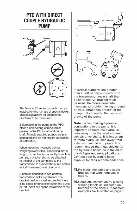
46. Place the pump into the PTO output mounting by aligning the splines as well as the pilot. Align the thru-bolt mounting holes and insert the capscrews with flat washers and torque all 4 capscrews to 40-42 ft.lbs.
Note: The pump orientation is with the pump body offset pointing DOWN.
FR64/67 Installation
47. If your system contains a driveline between the PTO and another product and if are experiencing noise in your system that was not heard before, the angularity or phasing of your driveline may be the cause. Check the driveline angularity and reduce the total angularity recommended by the chart and be sure that the PTO shaft is parallel within 1.5° to the pump shaft (or driven unit). Note: For installations with angles in the top and side views, use this formula to compute the true joint angle (TJA): TJA = A2+B2
If vertical supports are greater than 20 off of perpendicular with the transmission main shaft then a reinforced “Z” bracket must be used. Reinforce horizontal members to prohibit flexing at bend or weld. Attach the bracket at the pump bolt closest to the center of gravity of the pump.
Note: When making hydraulic connections to the pump, it is important to route the hydraulic lines away from the front and rear vehicle drive shafts. It is important to route hydraulic lines away from exhaust manifold and pipes. It is recommended that heat shields for the hydraulic hoses be installed on the 4x4 gas engine applications. Contact your hydraulic hose supplier for their recommendations.
48. Re-install the cable and cable bracket that were removed in step 4.
49. Complete installation by placing warning labels as indicated on borders of the decals. Placement examples are illustrated on page 5.
The Muncie PF series hydraulic pumps installed on the 4x4 are of special design. This design allows for interference problems to be minimized.
Before bolting the pump to the PTO, place a non-seizing compound or grease on the PTO shaft and pump shaft. Muncie supplied pumps are pre-lubricated and do not require lubrication at installation.
When mounting hydraulic pumps weighing over 20 lbs., exceeding 12" in length, or has tandem or multiple section pumps, a bracket should be attached to the rear of the pump and to the transmission to support the pump and to inhibit movement in all directions.
A bracket attached to two or more transmission bolts is preferred. The bracket design should assure that there is no stress or force exerted on the pump or PTO shaft during the installation of the bracket.
PTO WITH DIRECT COUPLE HYDRAULIC
PUMP
30
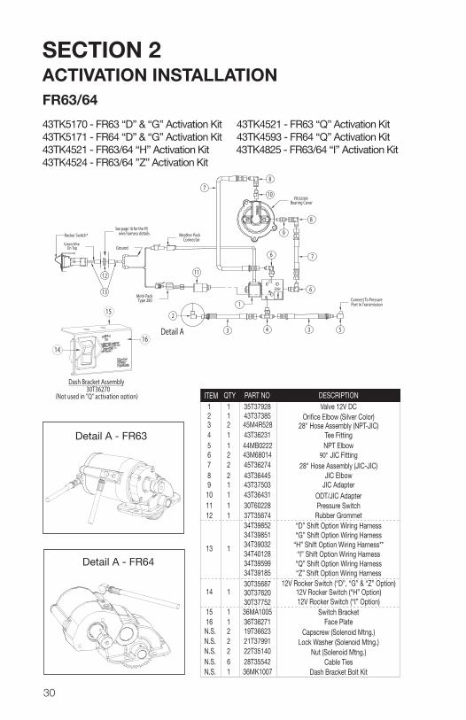
SECTION 2 ACTIVATION INSTALLATIONFR63/64
Connect To PressurePort In Transmission
5343
2
6
76
8
9
8
10FR 63/64
Bearing Cover
7
11CL
IN
EXH
Metri PackType 280
Weather PackConnector
12
GroundGreen Wire
On Top
See page 16 for the FRwire harness details.Rocker Switch*
1. Install the appropriate shifter kit components as described.
2. With the ignition switch on (but engine not running) turn on the PTO control switch and listen for the solenoid valve. You should be able to hear the valve snap open. If not, check for a poor ground connec tion. This must be a bare metal contact to battery ground.
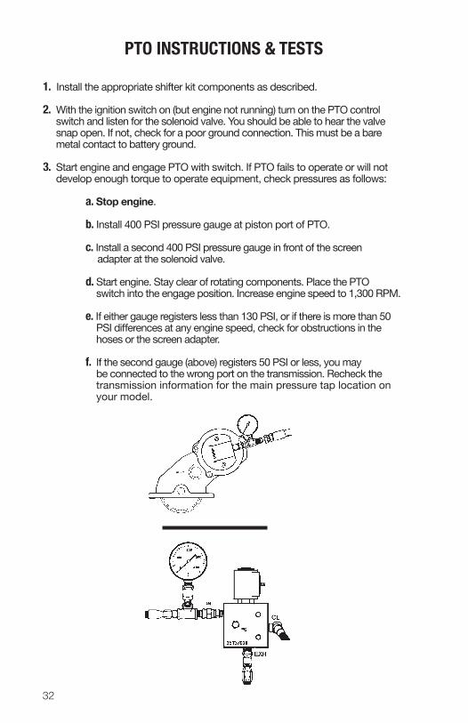
3. Start engine and engage PTO with switch. If PTO fails to operate or will not develop enough torque to operate equipment, check pres sures as follows:
a. Stop engine.
b. Install 400 PSI pressure gauge at piston port of PTO.
c. Install a second 400 PSI pressure gauge in front of the screen adapter at the solenoid valve.
d. Start engine. Stay clear of rotat ing components. Place the PTO switch into the engage position. Increase engine speed to 1,300 RPM.
e. If either gauge registers less than 130 PSI, or if there is more than 50 PSI differences at any engine speed, check for obstructions in the hoses or the screen adapter.
f. If the second gauge (above) reg isters 50 PSI or less, you may be connected to the wrong port on the transmission. Recheck the transmission information for the main pressure tap location on your model.
PTO INSTRUCTIONS & TESTS
SECTION 3OPERATOR’S MANUAL
33
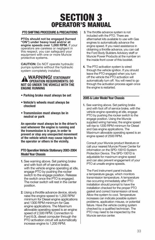
3. The throttle advance system is not included with the PTO. There are aftermarket kits available to use with Gas engines to automatically advance the engine speed. If you need assistance in obtaining a throttle advance, you can call the Ford Body Builders Advisory staff or Muncie Power Products at the number on the inside front cover of this booklet.
4. The PTO activation system is wired through the vehicle ignition. If you should leave the PTO engaged when you turn off the vehicle the PTO activation will automatically turn off. You will need to go through the activation process again once the engine is restarted.
2005 & Later Model Year Chassis
1. See warning above. Set parking brake and with foot off of service brake, with the vehicle engine operating at idle, engage PTO by pushing the rocker switch to the engage position. Using the Muncie supplied wiring harness; the engine speed will rise to 1200 RPM minimum for Diesel and Gas engine applications. The Maximum allowable operating speed is an engine speed of 2500 RPM.
Consult your Muncie product literature or call your nearest Muncie Power Center for information on the SPD-1001D System Protection Device. The SPD-1001D is adjustable for maximum engine speed and can also prevent engagement of your PTO at unsafe engine speeds.
The Ford instrument panel includes a temperature gauge, which monitors transmission temperature. A temperature rise occurring immediately after PTO installation should prompt to have the installation checked for the proper PTO gasket and correct transmission oil level. Allow the system to cool. Temperature increases can indicate possible system problems, applica tion misuse, or potential failure. Have the vehicle cooling system checked by a qualified technician. The PTO may need to be inspected by the Muncie service center.
PTO SHIFTING PROCEDURE & PRECAUTIONS
PTOs should not be engaged (turned “ON”) under heavy load and/or at engine speeds over 1,000 RPM. If your operators are careless or negligent in this respect, you can safeguard your equipment with one or more Muncie protective systems. CAUTION: Do NOT operate hydraulic pumps systems without the hydraulic system completely installed.
WARNING! STATIONARY OPERATION REQUIREMENTS: DO NOT GO UNDER THE VEHICLE WITH THE ENGINE RUNNING
• Parking brake must always be set • Vehicle’s wheels must always be
chocked
• Transmission must always be in neutral or park
An operator must always be in the driver’s seat whenever the engine is running and the transmission is in gear, in order to prevent or stop any unexpected movement of the vehicle which may cause injuries to the operator or others in the vicinity.
PTO Operation Vehicle Stationary 2003 -2004 Model Year Chassis
1. See warning above. Set parking brake and with foot off of service brake, with the vehicle engine operating at idle, engage PTO by pushing the rocker switch to the engage position. Release the switch once the PTO is engaged. The rocker switch will rest in the center position.
2. Using a throttle advance device, slowly raise the engine speed to 1,200 RPM minimum for Diesel engine applications and 1300 RPM minimum for Gas engine applications. The Maximum allowable oper ating speed is an engine speed of 2,500 RPM. Connection to Ford 6.0L diesel computer through the PTO activation circuit will auto matically increase engine to 1,200 RPM.
34
PTO OPERATION VEHICLE MOBILE1. With the vehicle engine operating at idle and the parking brake set, engage the
PTO by pushing the rocker switch to the “engage” position. Release the switch once the PTO is engaged. The rocker switch will rest in the center “on” position. (2-position switch on the 2005 and later vehicles are on/off switches).
2. With the parking brake applied, shift the transmission into a drive or reverse selection. The PTO will stop spinning until the brake is released and the vehicle has started moving. Stopping the vehicle will cause the PTO to stop because it is torque converter dependent. Once the transmis sion selector is shifted to “park” or “neutral” the PTO will start to spin.
3. The Torqshift® transmission is designed to allow PTO operation in all gears including over-drive.
PTO MaintenanceThe Power Take-Off, being an integral part of the transmission, should be serviced at the same intervals as the transmission. Changing transmission fluid should follow the interval recommended by the vehicle manufacturer for severe service. Transmission oil level is important. Checking for PTO leaks and checking the transmission oil level should be done on a regular basis.
The Power Take-Off is also part of a system. The PTO system may include the activation control parts, a driveshaft, or hydraulic pump. This PTO system requires periodic checks and service. Typically the interval for maintenance checks of the PTO system depends on the application of the system. Every time the chassis is lubricated or a mechanic is under the vehicle the PTO sys tem should be checked and/or serviced. For severe duty PTO system applica tions, it is recommended that the system be checked for service every 100 hours of use (this guideline can be adjusted based on past service history once you have it established). Service should include checking and lubricating direct mount pump shaft connections. PTO gears can be checked for wear by removing the PTO. If pitting, galling, cracking, or deformation of the gears or splines has occurred, then the PTO needs to be rebuilt or replaced.
Within the first week of use, recheck installation of PTO. Check for leaks and loose mounting hardware. At regular maintenance intervals, check adjustments and lubricate moving parts, tighten and repair connections, mounting hard ware. Pumps that are mounted directly to the PTO output require the application of an anti-seize or a high temperature and/or high pressure grease (Muncie PTOs are initially supplied with required grease). The purpose of this grease is to help make PTO easier to service and to reduce the effects of fretting corrosion on the mating PTO and pump shafts. PTO applications under severe duty cycles and/or high torque requirements may require servicing this shaft connection by periodically re-greasing shafts. Fretting corrosion cannot be stopped by apply ing grease; the grease is only a deterrent.
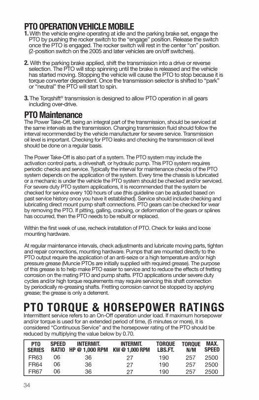
PTO TORQUE & HORSEPOWER RATINGSIntermittent service refers to an On -Off operation under load. If maximum horsepower and/or torque is used for an extended period of time, (5 minutes or more), it is considered “Continuous Service” and the horsepower rating of the PTO should be reduced by multi plying the value below by 0.70.
FR63FR64FR67
060606
363636
272727
190190190
257257257
250025002500
PTO SERIES
SPEED RATIO
INTERMIT. HP @ 1,000 RPM
INTERMIT. KW @ 1,000 RPM
TORQUELBS.FT.
MAX.SPEED
TORQUEN/M
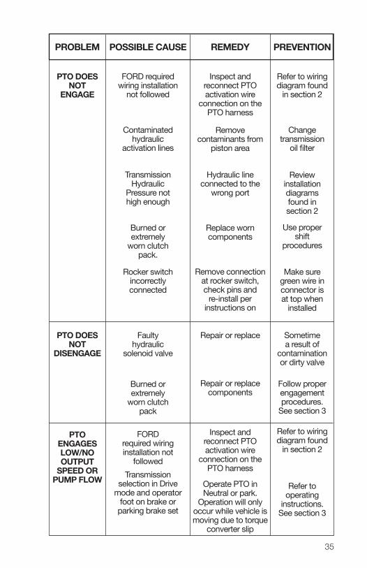
POSSIBLE CAUSE
FORD required wiring installation
not followed
Contaminated hydraulic
activation lines
Transmission Hydraulic
Pressure not high enough
Rocker switch incorrectly connected
Burned or extremely
worn clutch pack.
Burned or extremely
worn clutch pack
Faulty hydraulic
solenoid valve
FORD required wiring installation not
followedTransmission
selection in Drive mode and operator
foot on brake or parking brake set
PREVENTION
Refer to wiring diagram found
in section 2
Change transmission
oil filter
Review installation diagrams found in section 2
Make sure green wire in connector is at top when
installed
Use proper shift
procedures
Follow proper engagement procedures.
See section 3
Sometime a result of
contamination or dirty valve
Refer to wiring diagram found
in section 2
Refer to operating
instructions. See section 3
REMEDY
Inspect and reconnect PTO activation wire
connection on the PTO harness
Remove contaminants from
piston area
Hydraulic line connected to the
wrong port
Remove connection at rocker switch, check pins and
re-install per instructions on
Replace worn components
Repair or replace components
Repair or replace
Inspect and reconnect PTO activation wire
connection on the PTO harness
Operate PTO in Neutral or park.
Operation will only occur while vehicle is moving due to torque
converter slip
PROBLEM
PTO DOES NOT
ENGAGE
PTO DOES NOT
DISENGAGE
PTO ENGAGES LOW/NO OUTPUT
SPEED OR PUMP FLOW
35
POWER TAKE-OFF WARRANTYThe Muncie Power Take-Off is warranted to be free of defects in material or workmanship and to meet Muncie’s standard written specifications at the time of sale. Muncie’s obligation and liability under this warranty is expressly limited to repairing or replacing, at Muncie’s option, within one year after date of original installation any defective part or parts or any product not meeting the specifications.
THIS WARRANTY IS IN LIEU OF ALL OTHER WARRANTIES, EXPRESSED OR IMPLIED. MUNCIE MAKES NO WARRANTY OF MERCHANTABILITY OR OF FITNESS FOR ANY PARTICULAR PURPOSE. MUNCIE’S OBLIGATION UNDER THIS WARRANTY SHALL NOT INCLUDE ANY TRANSPORTATION CHARGES OR COSTS OF INSTALLATION OR ANY LIABILITY FOR DlRECT, lNDIRECT SPECIAL, lNClDENTAL, OR CONSEQUENTIAL DAMAGES OR DELAY. THE REMEDIES SET FORTH HEREIN ARE EXCLUSIVE, AND MUNCIE’S LIABILITY WITH RESPECT TO ANY CONTRACT OR SALE OR ANYTHING DONE IN CONNECTION THEREWITH, WHETHER IN CONTRACT, lN TORT, UNDER ANY WARRANTY, OR OTHERWISE, SHALL NOT, EXCEPT AS EXPRESSLY PROVIDED HEREIN, EXCEED THE PRICE OF THE PRODUCT OR PART ON WHICH SUCH LIABILITY IS BASED.
If requested by Muncie, products or parts for which a warranty claim is made are to be returned transportation prepaid to a Muncie Service Center. Any installation or use not in accordance with catalogue or package instructions, other improper use, operation beyond capacity, substitution of parts not approved by Muncie, use with equipment other than the equipment on which the Power Take-Off is first installed, or alteration or repair made to the Power Take-Off other than at a Muncie Service Center shall void this warranty. No employee or representative of Muncie is authorized to change this warranty in any way or to grant any other warranty.
201 East Jackson Street • Muncie, Indiana 47305800-367-7867 • Fax 765-284-6991
[email protected] • www.munciepower.comSpecifications are subject to change without notice.