REPORT TO: TIGHAR Oxford, PA Attn: Richard Gillespie Purchase Order No.: Courtesy Fractographic Analysis of Artifact 2-2-V-1 MMR Project No. 128927 August 27, 2019 From: Massachusetts Materials Research _____________________________ Veda-Anne Ulčickas Senior Materials Engineer
Transcript
REPORT TO:
TIGHAR Oxford, PA
Attn: Richard Gillespie
Purchase Order No.: Courtesy
Fractographic Analysis of Artifact 2-2-V-1
MMR Project No. 128927
August 27, 2019
From: Massachusetts Materials Research
_____________________________ Veda-Anne Ulčickas
Senior Materials Engineer
MMR Project No. 128927 Page 1
BACKGROUND AND INVESTIGATION The International Group for Historic Aircraft Recovery (TIGHAR) submitted Artifact 2-2-V-1 to Massachusetts Materials Research (MMR) for analysis of fractures present on the artifact. This artifact was recovered on the island of Nikumaroro in 1991, and a current working theory posits it may be a piece of the Lockheed Electra 10 piloted by Amelia Earhart during her second around the world attempt. Specifically, a region on that Electra 10 modified by a patch installed just prior to the 1 June 1937 departure from Miami, FL for San Juan, Puerto Rico has been and is currently under scrutiny by TIGHAR for construction details to compare against Artifact 2-2-V-1. Any fracture features still discernable on the piece would assist in efforts either to match or rule out the fragment as a part of that Electra. This fragment has been modified from its original as-found condition to accommodate necessary mechanical and chemical analyses by various laboratories to determine its alloy of construction and strength. The summary of those findings is that the sheet is a clad product whose base metal is similar to UNS A92024 (aluminum alloy 2024) with trace levels of chromium, nickel and zinc that are more similar to the B-17 Shoo-Shoo Baby from the early 1940s than two known Electra samples tested for comparison. Mechanical testing results indicated an ultimate strength of 52,712 PSI, a yield strength of 41,611 PSI, and an elongation of 26%. Mechanical results for comparison aircraft skins did not follow any discernable pattern based upon year of manufacture. Because this piece is possibly a patch onto an aircraft rather than part of original construction, chemical and mechanical signatures may not align well with original parts. RESULTS Visual and Stereomicroscope Examinations The 2-2-V-1 artifact as delivered to MMR was a piece of curved aluminum skin approximately 24.5 inches by 19 inches at its widest and longest regions, and 0.032-inch thick. A small piece of the artifact approximately 1 ⅓-inch by ¾-inch that had broken off during post-recovery handling was also present. The 2-2-V-1 artifact possessed four rows of 3/16-inch rivet holes and a partial fifth row containing three 5/32-inch rivet holes at a feature colloquially called the tab. On the opposite side of the artifact was a tear referred by TIGHAR as possibly having been located at station 307 of the Earhart aircraft. For convenient reference purposes, “tab” and “Sta. 307” are used in this report as labels for those features. These are shown in Figure 1. Overall, the artifact presented a grey, oxidized aluminum appearance with isolated regions of buff-colored calcareous deposits and thin, green discolorations. Both the buff and green deposits were reported to have been previously tested and found to be consistent with coral and algal growths. Isolated larger radius bends and cracks along rivet holes were present. The rivet hole cracking within the body of the piece and cracks on three edges of the artifact presented the general appearance of fatigue cracking, while the jagged edge along which the tab was located appeared torn in overload. The Sta. 307 tear feature itself presented the overall pattern of a fatigue crack with post-cracking deformation of its metal flaps. Some tear type features were present along the Sta. 307 edge at the 1.5 ft. mark of the scale in Figure 1. Tearing can occur
MMR Project No. 128927 Page 2
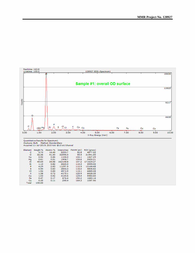
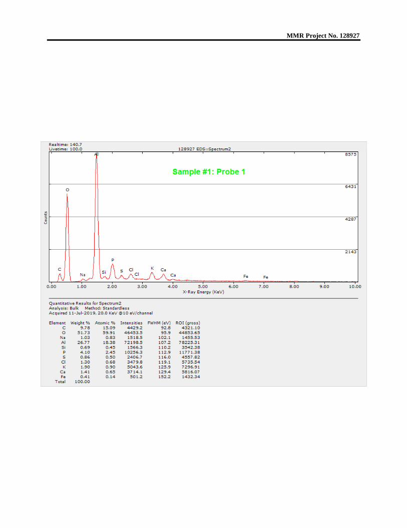
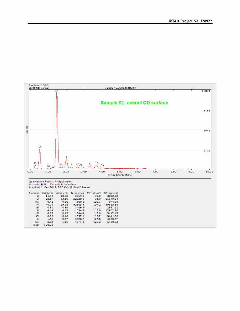
when thin sheet aluminum is dragged along a coral reef. Subsequent fatigue fractures could occur due to wave action and tidal surging. The outer radius of the artifact possessed the letters “AD” near the tab, a “6-” or “-9” mark (depending upon which way is properly “up”) near Sta. 307, and a possible small P or D over a 9 near the tab. No such discernable markings were present on the inner radius surface. The lines of smaller rivet holes were 4 ¼-inch apart, although that was not exact for all the row spacings. These rivet holes were located 1-inch apart. An intact rivet was present in line with the Sta. 307 feature and has been the subject of previous examinations. The partial line of larger rivet holes exhibited irregular spacing and linear misalignment. The features discussed are shown in Figures 2 through 11. To determine whether any radial markings, beach marks, or any other larger fracture features were present to indicate the location of fracture origins or direction of fracture progression, the artifact and its small separated piece were examined with a stereomicroscope. This examination was generally unrevealing, as all fracture surfaces examined exhibited post-fracture damage and corrosion, Figures 12 and 13. Scanning Electron Microscope Examination The small separated piece of 2-2-V-1 presented the opportunity to perform scanning electron microscope (SEM) examinations on two fracture surfaces without any additional cutting or alteration to the artifact. The higher magnifications and greater depth of field available with an SEM versus a traditional light microscope allows the examination of the fine fracture features that reveal fracture mode, when they have not been consumed by corrosion or damaged by mechanical or other action. For this examination, Fracture 1 on this segment is the original edge fracture of the artifact, along the left side of the piece in Figure 1. Fracture 2 on this segment represents a crack leading into the 2-2-V-1 body from Fracture 1. In both cases, this examination revealed that the fracture surfaces were extensively damaged by post-fracture mechanical rubbing and corrosion, Figures 14 through 20. This is expected of aluminum and its alloys when exposed to seawater and wave action, especially if that exposure has been prolonged, as would be the case for an aircraft fragment pre-dating World War II. Coral growth on this artifact is consistent with prolonged exposure. To determine whether the fragment possessed any unusual elemental exposure on its surface that may assist in identification, the outer radius surface of this separated piece was analyzed using energy dispersive x-ray spectroscopy, or EDS. This is a semi-quantitative microchemical analysis technique that uses equipment attached to a SEM to reveal the elements present in an analyzed sample or region, along with their approximate amounts. While not as accurate as wet chemical methods such as inductively coupled plasma spectroscopy (ICP), EDS is ideal for layered samples, samples too small for ICP, and for detecting aggressive elements in corrosion debris. The results of this analysis are summarized below. The original spectrograms are
MMR Project No. 128927 Page 3
appended to this report for reference. The Sample 1 and Sample 2 notations refer to two locations on this fragment, one of which (Sample 2) was examined metallurgically.
Table I EDS Analysis Results, Outer Radius Surface
Region Analyzed Figure Elements Detected (approx. wt. %)
These results revealed that the outer radius surface of the 2-2-V-1 fragment possessed only elements associated with seawater exposure, coral skeletons, and the aluminum alloy of construction. Metallurgical Examination A previous examination of 2-2-V-1 prior to arrival at MMR revealed that the material of construction of the artifact was more brittle in the region of some bending and darker discoloration than nearby. That examiner postulated that the artifact may have been exposed to excessive heat or fire, accounting for the discoloration and brittleness. To verify whether or not high heat or fire was a factor in this regional difference of behavior in the artifact’s material, two sections were prepared for metallurgical examination. One of the sections was removed from the separated fragment (Sample 2 in Table I), and the other was cut from a nearby region that had been the source of either a tensile test specimen or a chemical analysis sample. These two samples were mounted in plastic and ground, polished, and etched to reveal microstructure. The resulting metallurgical mounts provided planar cross-sectional views of the artifact material from outer radius to inner radius, and included a region of original artifact edge from the separated fragment. The mounts were examined in both the as-polished and the etched
MMR Project No. 128927 Page 4
conditions. The locations from which these mounts were created are shown in Figures 23 through 26. This examination confirmed that extensive corrosion was present on the artifact surfaces and fractures. The corrosion was general, pitting, and intergranular attack forms, all of which would be expected from an aluminum alloy fragment submerged in seawater, Figures 27 through 31. The original edge fracture present at one end of the separated fragment mount did not possess enough base metal grain deformation to have fractured via tearing (i.e. overload), Figure 32. While the extensive corrosion prevented observation of the actual fracture mode, metallurgical analysis ruled out overload in this region. Examination of the base metal grain structure of the separated fragment and possible heat affected region revealed no evidence of grain growth, recrystallization, second phase form or size alteration, grain boundary melting, etc. Cold work was present at the possible heat affected region, Figures 33 and 34. This indicates that the more brittle behavior of the possible heat affected region was not due to heat, but instead due to the effects of cold work. The microstructure of both mounted cross-sections was typical of solution treated 2024 aluminum. CONCLUSIONS This examination revealed that the 2-2-V-1 artifact possessed no microscopic fracture features that would allow confirmation of the fracture mode of its various cracks and separations. Corrosion and mechanical rubbing damage were present. This is expected of an aluminum piece that was at one point submerged in the ocean and would be exposed to wave and sand dragging action. Metallurgical examination revealed that more brittle behavior of the artifact material in a possibly heat affected region was actually due to cold work effects. This examination also revealed that the artifact fracture surface grain structure along that same edge was not deformed enough to have occurred as the result of overload fracture in the region examined. The microstructure of the artifact material was typical of solution treated 2024 aluminum alloy.
MMR Project No. 128927
Figure 1: Overall view of 2-2-V-1 with the Tab and Sta. 307 features labelled.
Figure 2: The “AD” logo near the tab. Two other instances of this logo were also present.
This was the best defined.
TAB
Sta 307
MMR Project No. 128927
Figure 3: Smaller rivet hole rows were spaced 4.25-inches apart.
Figure 4: Smaller rivet holes were 1-inch apart. The intact rivet is shown.
MMR Project No. 128927
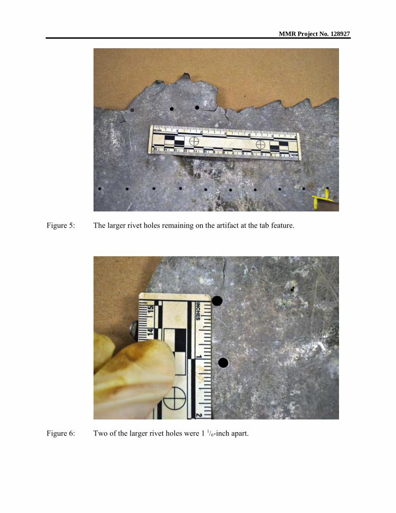
Figure 5: The larger rivet holes remaining on the artifact at the tab feature.
Figure 6: Two of the larger rivet holes were 1 1/6-inch apart.
MMR Project No. 128927
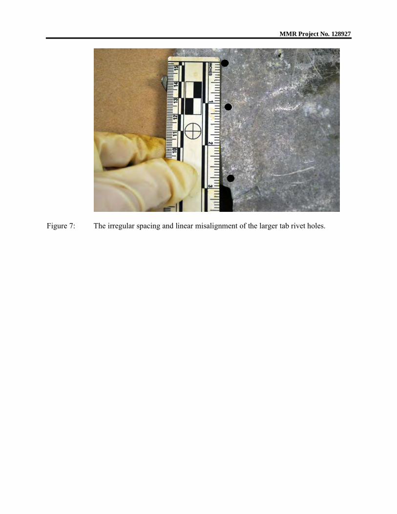
Figure 7: The irregular spacing and linear misalignment of the larger tab rivet holes.
MMR Project No. 128927
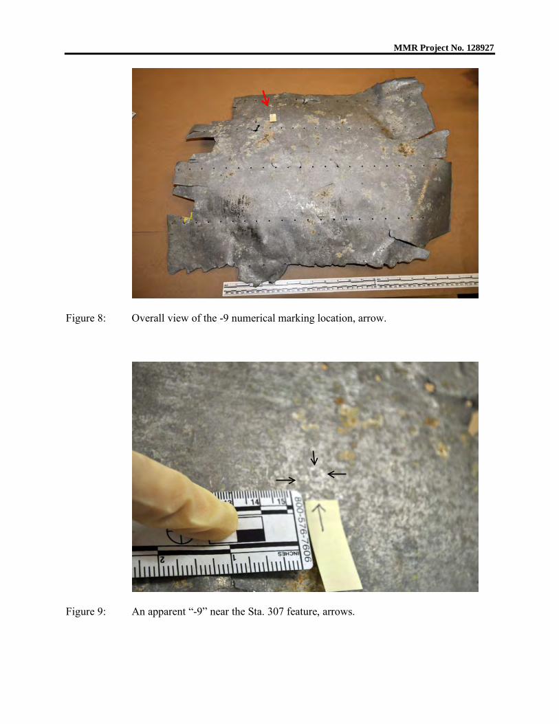
Figure 8: Overall view of the -9 numerical marking location, arrow.
Figure 9: An apparent “-9” near the Sta. 307 feature, arrows.
MMR Project No. 128927
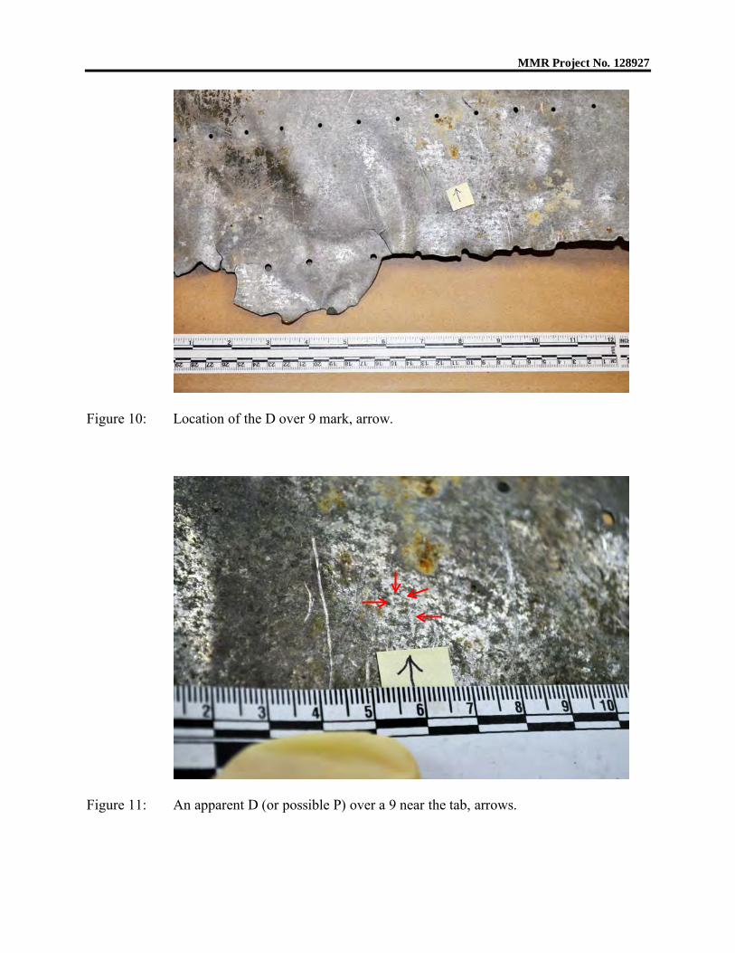
Figure 10: Location of the D over 9 mark, arrow.
Figure 11: An apparent D (or possible P) over a 9 near the tab, arrows.
MMR Project No. 128927
Mag. 28.1 : 1 50 mils
A typical fracture surface on 2-2-V-1, representative of all fractures examined.No fracture features were discernable.
Mag. 37.4 : 1 20 mils
A higher magnification view of a typical fracture showing post-fracture rubbingdamage.
Figure 12:
Figure 13:
MMR Project No. 128927
Figure 14: Fracture 1 overall with areas 1 and 2 marked.
Figure 15: Fracture 1 area 1 detail showing mechanical rubbing and no fracture features.
MMR Project No. 128927
Figure 16: Fracture 1 area 2 detail showing mechanical rubbing and no fracture features.
MMR Project No. 128927
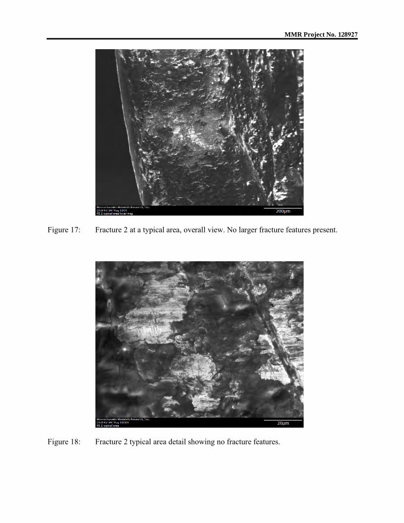
Figure 17: Fracture 2 at a typical area, overall view. No larger fracture features present.
Figure 18: Fracture 2 typical area detail showing no fracture features.
MMR Project No. 128927
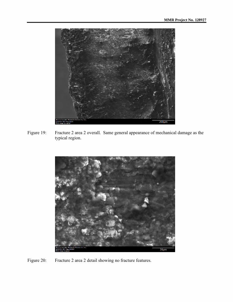
Figure 19: Fracture 2 area 2 overall. Same general appearance of mechanical damage as the typical region.
Figure 20: Fracture 2 area 2 detail showing no fracture features.
MMR Project No. 128927
Figure 21: EDS Probes 1 and 2 locations.
Figure 22: EDS Probes 3 and 4 locations.
MMR Project No. 128927
Figure 23: Overall view of metallurgical mount location sources.
Figure 24: Detail of mounts, mount cards, and aligned location sources for the mounted
specimens.
MMR Project No. 128927
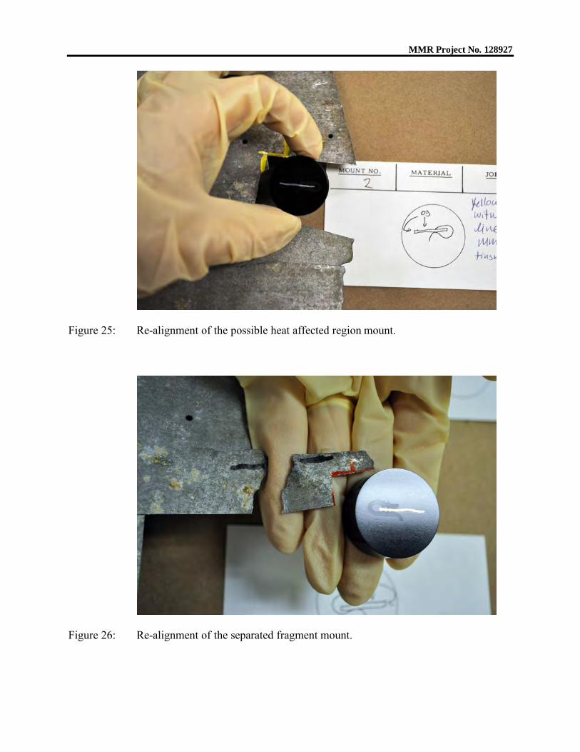
Figure 25: Re-alignment of the possible heat affected region mount.
Figure 26: Re-alignment of the separated fragment mount.
MMR Project No. 128927
Mag. 520 : 1 2 mils
Separated fragment outer radius corrosive attack with intergranular attack atarrows. As-polished.
Mag. 520 : 1 2 mils
Detail of Figure 27 showing remnants of surface cladding, yellow arrows, andcorrosion along second phases in base metal, red arrows. As-polished.
Figure 27:
Figure 28:
LMazur
Line
LMazur
Line
LMazur
Line
LMazur
Line
MMR Project No. 128927
Mag. 129 : 1 10 mils
Separated fragment original artifact fracture surface showing extensive corrosionand rounded fracture surface region. As-polished.
Mag. 520 : 1 2 mils
Detail of fracture surface corrosion from Figure 29.
Figure 29:
Figure 30:
MMR Project No. 128927
Mag. 259 : 1 5 mils
Typical pitting on the possible heat affected region surface. As-polished.
Mag. 129 : 1 10 mils
Etching revealed not enough grain deformation for overload fracture at separatedpiece original 2-2-V-1 fracture. Etchant: Keller’s.
Figure 31:
Figure 32:
MMR Project No. 128927
Mag. 1290 : 1 1 mils
Detail, separated fragment grain structure. Etchant: Keller’s.
Mag. 1290 : 1 1 mils
Detail, cold work and no heat effects in possible heat affected region grainstructure. Etchant: Keller’s.
Figure 33:
Figure 34:
MMR Project No. 128927
MMR Project No. 128927
MMR Project No. 128927
MMR Project No. 128927
MMR Project No. 128927
MMR Project No. 128927
MMR letters and reports apply to the specific materials, products, or processes tested, examined, surveyed, inspected, or calculated; and are not necessarily indicative of the qualities of apparently identical or similar materials, products, or processes. The liability of Massachusetts Materials Research, Inc., with respect to the services rendered, shall be limited to the amount of the consideration paid for such services and not include any consequential damages.