Fracture behavior of nanotube–polymer composites: Insights on surface roughness and failure mechanism Michael Shtein a , Roey Nadiv a , Noa Lachman b , H. Daniel Wagner b , Oren Regev a,⇑ a The Ilse Katz Institute for Nanoscale Science and Technology, The Department of Chemical Engineering, Ben-Gurion University of the Negev, 84105 Beer-Sheva, Israel b Department of Materials and Interfaces, Weizmann Institute of Science, 76100 Rehovot, Israel article info Article history: Received 21 March 2013 Received in revised form 3 July 2013 Accepted 13 July 2013 Available online 31 July 2013 Keywords: A. Carbon nanotubes A. Nanocomposites B. Fracture toughness C. Failure criterion Fractured surface roughness abstract The utilization of highly branched polymer (e.g., epoxy resins) in engineering applications is often limited by their brittle nature (low fracture toughness). Loading the polymer matrix by fillers such as individual nanotubes is a promising alternative to enhance fracture toughness without compromising other mechanical properties. However, to fully understand the nanotubes toughening role and correctly char- acterize the nanocomposite failure mechanisms, a complete exfoliation of the nanotubes aggregates into individual nanotubes is essential. In this work, we embed only individual nanotubes in the polymer matrix using a novel dispersion method. The individual nanotube concentration in the composite is accu- rately determined. We achieve a record fracture toughness enhancement and, for the first time, demon- strate a coherent quantitative correlation between the fracture toughness and the surface roughness. Finally, comprehensive statistical investigation of the nanotube failure mechanisms shows that carbon nanotubes fail via fracture mechanism, while tungsten di-sulfide nanotubes via pullout mechanism. The failure mechanism could be predicted by the slope of the surface roughness vs. fracture toughness curve. Ó 2013 Elsevier Ltd. All rights reserved. 1. Introduction Epoxy resins are widely used in various industrial applications due to their superior properties such as resistance to corrosion, thermal and mechanical shocks, superior electrical insulation, light weight, and ease of processing [1]. However, the usefulness of some epoxy resins is often limited by their brittle nature (low fracture toughness (FT)), stemming from heavy crosslinking. Indeed, the addition of traditional fillers such as rubber particles has been shown to toughen the epoxy resins [2], but often at the expense of other mechanical properties (e.g., elastic modulus, strength, strain, and thermal properties) as a result of local stress concentrations and microcracking. Individual nanotube (NT) fillers such as carbon or tungsten di-sulfide nanotubes (CNT and WS 2 NT) with exceptional mechanical properties [3,4] and large surface area [5] represent a promising alternative to increase the epoxy’s FT without compromising other properties [6–8]. The nanometric size of the NT prevents stress concentration and their large surface area increase the interaction with the polymer matrix, enhancing the stress-transfer mechanism. Although beneficial to stress-transfer, the large surface area of the NT induces excessive aggregation [9–14] due to fairly strong interfacial interaction by van der Waals forces. NT aggregation negates any benefit associated with their nanoscale dimension and impairs the stress-transfer due to limited surface area. Therefore, the NT aggregates behave in some cases as microscopic defects. It is clear from the above that for any type of NT fillers it is essential to develop dispersion methods yielding individual NTs (isolated NT or small aggregates, up to 4 tubes [15]) and yet applicable through macroscopic processing. Suppres- sion of NT aggregation can be achieved by controlling the NT sur- face forming either electrostatic or steric repulsion. There are two main approaches to achieve that: (i) covalently attaching hydro- philic groups to the NT surface (chemical functionalization) [16] (ii) non-covalently adsorbing dispersing molecules (dispersants) [6,17–19]. Although approach (i) may improve interfacial adhesion between the resin and the NT, it usually results in structural de- fects in the NTs, reducing their strength, stiffness and surface area available for stress-transfer. While approach (ii) drastically reduces NT structural defects, it comes with a number of technological dis- advantages: The NTs are dispersed in a solvent that needs to be evaporated from the polymer matrix, which calls for low boiling point solvents. Moreover, the low concentration of exfoliated NTs (<1 wt.%) in dispersions requires evaporation of a large volume of 0266-3538/$ - see front matter Ó 2013 Elsevier Ltd. All rights reserved. http://dx.doi.org/10.1016/j.compscitech.2013.07.016 Abbreviations: CNT, carbon nanotubes; FT, fracture toughness; NCM, nanocom- posite materials; NT, nanotube; SR, surface roughness; SWLIM, scanning white light interference microscopy; WS 2 NT, tungsten disulfide nanotubes. ⇑ Corresponding author. Tel.: +972 86472145; fax: +972 8 6472916. E-mail address: [email protected](O. Regev). Composites Science and Technology 87 (2013) 157–163 Contents lists available at ScienceDirect Composites Science and Technology journal homepage: www.elsevier.com/locate/compscitech
Transcript
Composites Science and Technology 87 (2013) 157–163
Michael Shtein a, Roey Nadiv a, Noa Lachman b, H. Daniel Wagner b, Oren Regev a,⇑a The Ilse Katz Institute for Nanoscale Science and Technology, The Department of Chemical Engineering, Ben-Gurion University of the Negev, 84105 Beer-Sheva, Israelb Department of Materials and Interfaces, Weizmann Institute of Science, 76100 Rehovot, Israel
a r t i c l e i n f o
Article history:Received 21 March 2013Received in revised form 3 July 2013Accepted 13 July 2013Available online 31 July 2013
The utilization of highly branched polymer (e.g., epoxy resins) in engineering applications is often limitedby their brittle nature (low fracture toughness). Loading the polymer matrix by fillers such as individualnanotubes is a promising alternative to enhance fracture toughness without compromising othermechanical properties. However, to fully understand the nanotubes toughening role and correctly char-acterize the nanocomposite failure mechanisms, a complete exfoliation of the nanotubes aggregates intoindividual nanotubes is essential. In this work, we embed only individual nanotubes in the polymermatrix using a novel dispersion method. The individual nanotube concentration in the composite is accu-rately determined. We achieve a record fracture toughness enhancement and, for the first time, demon-strate a coherent quantitative correlation between the fracture toughness and the surface roughness.Finally, comprehensive statistical investigation of the nanotube failure mechanisms shows that carbonnanotubes fail via fracture mechanism, while tungsten di-sulfide nanotubes via pullout mechanism.The failure mechanism could be predicted by the slope of the surface roughness vs. fracture toughnesscurve.
� 2013 Elsevier Ltd. All rights reserved.
1. Introduction
Epoxy resins are widely used in various industrial applicationsdue to their superior properties such as resistance to corrosion,thermal and mechanical shocks, superior electrical insulation, lightweight, and ease of processing [1]. However, the usefulness ofsome epoxy resins is often limited by their brittle nature (lowfracture toughness (FT)), stemming from heavy crosslinking.Indeed, the addition of traditional fillers such as rubber particleshas been shown to toughen the epoxy resins [2], but often at theexpense of other mechanical properties (e.g., elastic modulus,strength, strain, and thermal properties) as a result of local stressconcentrations and microcracking. Individual nanotube (NT) fillerssuch as carbon or tungsten di-sulfide nanotubes (CNT and WS2NT)with exceptional mechanical properties [3,4] and large surface area[5] represent a promising alternative to increase the epoxy’s FTwithout compromising other properties [6–8]. The nanometric sizeof the NT prevents stress concentration and their large surface area
increase the interaction with the polymer matrix, enhancing thestress-transfer mechanism. Although beneficial to stress-transfer,the large surface area of the NT induces excessive aggregation[9–14] due to fairly strong interfacial interaction by van der Waalsforces. NT aggregation negates any benefit associated with theirnanoscale dimension and impairs the stress-transfer due to limitedsurface area. Therefore, the NT aggregates behave in some cases asmicroscopic defects. It is clear from the above that for any type ofNT fillers it is essential to develop dispersion methods yieldingindividual NTs (isolated NT or small aggregates, up to �4 tubes[15]) and yet applicable through macroscopic processing. Suppres-sion of NT aggregation can be achieved by controlling the NT sur-face forming either electrostatic or steric repulsion. There are twomain approaches to achieve that: (i) covalently attaching hydro-philic groups to the NT surface (chemical functionalization) [16](ii) non-covalently adsorbing dispersing molecules (dispersants)[6,17–19]. Although approach (i) may improve interfacial adhesionbetween the resin and the NT, it usually results in structural de-fects in the NTs, reducing their strength, stiffness and surface areaavailable for stress-transfer. While approach (ii) drastically reducesNT structural defects, it comes with a number of technological dis-advantages: The NTs are dispersed in a solvent that needs to beevaporated from the polymer matrix, which calls for low boilingpoint solvents. Moreover, the low concentration of exfoliated NTs(<1 wt.%) in dispersions requires evaporation of a large volume of
158 M. Shtein et al. / Composites Science and Technology 87 (2013) 157–163
solvent, some of which remains in the matrix and may result ininferior properties. The above arguments make the scaling-up ofapproach (ii) to industrial application impractical. Another ap-proach to overcome NTs aggregation is by applying high energyto break the dispersant-free NTs aggregates. This can be done bymechanical methods (iii) such as ultrasonication, high shear mix-ing in a solvent, calendering and ball milling, as well as a combina-tion of these methods in series or parallel [6,20–22]. However, thisapproach is usually the less effective since it results in structuraldefects [23] in the NTs, and in NTs’ re-aggregation due to the ab-sence of stabilizing agents.
The above dispersion approaches usually result only in partialNTs exfoliation. Thus, only part of the initial NTs is actually exfoli-ated and contributes to properties enhancement (namely, effectiveNTs concentration), while the rest (NT aggregates) impairs theproperties of the nanocomposite materials (NCM). Therefore, onlywhen we use the precisely measured effective NTs concentration(after removing the NT aggregates) in the investigation of NT fail-ure mechanisms we are able to evaluate the NTs toughening trueeffect.
Previous studies [24–27] on the failure mechanisms of NCMssuggested that NTs fail by two basic mechanisms: pull-out or frac-ture. The failure mechanism is dictated by NT length and NT–poly-mer interfacial adhesion. During crack propagation, the NTs tend tobe fractured in systems with strong filler–matrix interfacial adhe-sion; otherwise they are pulled-out of the matrix. The determina-tion of the failure mechanism is based in most cases only onimaging of fractured surface by transmission electron microscopy(TEM) [28,29] or scanning electron microscopy (SEM) [8,26].
In this paper we develop a dispersion method that yields mostlyindividual NTs (carbon or WS2), and measure their effective con-centration by our recently developed nanoparticles concentrationdetermination method [30]. Implementing these two methodseliminates the complex contribution of NT aggregates to themechanical properties of epoxy matrix, and results in a record frac-ture toughness enhancement. Furthermore, for the first time wedemonstrate a coherent correlation between the fracture tough-ness and the surface roughness of the fractured specimen, and clar-ify the failure mechanisms of nanocomposite materials.
2. Materials and methods
2.1. Materials
An epoxy resin, diglycidyl ether of bisphenol A (EPON 828,Momentive), polyether triamine hardener (JEFFAMINE� T-403,Momentive), pristine Multi-Wall Carbon Nanotubes (CNTs, Nano-cyl (NC7000)), tungsten disulfide inorganic nanotubes (WS2NTs,Nanomaterials), b-Lactoglobulin (BLAC, Sigma–Aldrich) and plu-ronic F-127 (F127, Sigma–Aldrich) were used as received.
2.2. Specimens preparation
2.2.1. NT dispersionNTs were mixed with a pre-prepared solution of dispersant in
deionized water, as indicated in Table 1. These NT-based disper-sions were then sonicated. Two sonication methods were used:Bath sonication (BS) was performed in an Elma sonic bath (model
Table 1Initial concentration of NTs and dispersants in sonicated dispersions.
NT type Dispersant type Dispersant concentration (mg/mL)
CNT F127 1.5WS2NT BLAC 2.0
S10; 30 W, 37 kHz, Singen). The water level in the bath was keptconstant and the vial (20 mL) was placed in the center of the bath.Tip sonication (TS) was performed in a VCX 400 instrument(400 W, 20 kHz, ltip, Sonics & Materials Inc.) at 38% intensity.The dispersion temperature was kept at 0 �C. Following sonicationthe dispersion was centrifuged (Megafuge 1.0, Heraues, 20 min at4000g) to accelerate precipitation. We found that longer centrifu-gation does not change the NT concentration. Following sonicationand centrifugation, a phase separation of exfoliated (supernatant)and aggregated (precipitate) NTs was performed by decantation.
2.2.2. NCM preparationFollowing decantation, the aqueous dispersions of NT (plastic
flasks 40 mL, diameter = 3 cm) were frozen by liquid nitrogen andplaced in a lyophilizer (Labconco Freezone 4.5) for 48 h. The lyoph-ilized NTs were added into the epoxy resin and then manuallymixed with a spatula for 5 min. Epoxy hardener was then added(1 g resin: 0.38 g hardener) to the NT/epoxy resin and the resultingNCM was manually mixed with a spatula and degassed for 10 minat 80 �C vacuum oven (P = 10 mbar). The NCM mixture was castinto variously-shaped silicone molds, and cured for 12 h at 80 �C.A similar preparation procedure was used for pure (reference)epoxy specimens (without filler addition and sonication/mixingsteps).
2.3. Specimens characterization
2.3.1. Concentration determination [30]Both supernatant and precipitate phases were filtered (using
0.22 lm pore size filter membranes (MF-Milipore)), washed (to re-move excess dispersant and to enhance thermogravimetric analy-sis (TGA) accuracy) and dried (120 �C for 1 h). The exact weights ofthe dried precipitate and dried supernatant phases were deter-mined by weighing the respective loaded filter membranes (andsubtracting the filter membranes weight). The NTs and dispersantweight percentages were then calculated from the thermograms(Mettler Toledo Star System, TGA/STDA85, 50 mL/min N2, 100 lLaluminum crucibles).
2.3.2. UV–vis spectroscopyThe supernatant-phase adsorption was measured by a double-
2.3.3. Electron microscopy of dispersions [31]NTs dispersions were characterized by Transmission Electron
Microscopy (TEM) or cryogenic TEM (cryo-TEM) (FEI Tecnai 12G2 TWIN TEM, 120 kV).
2.3.4. Mechanical characterizationFracture toughness (FT) of the NCM was measured using (at
least seven) small compact tension specimens (LRX, LLOYD instru-ments, 1 mm/min deformation rate, ASTM D 5045-91), which al-lows plane-strain conditions with relatively small specimens. Thespecimens were pre-cracked by tapping a razor blade into the rootof a machined notch. The presence of a sharp starter crack meansthat no energy contribution for crack initiation is included in themeasurement of FT.
NT concentration (mg/mL) Sonication procedure and (energy) (J)
2.0 Tip sonication (5040)6.0 Bath sonication (540)
M. Shtein et al. / Composites Science and Technology 87 (2013) 157–163 159
Young’s modulus and tensile strength of NCM were measuredby performing a three point bending test (LRX, LLOYD instruments,1 mm/min deformation rate, ASTM D 790).
Glass transition temperature (Tg) was measured using differen-tial scanning calorimetry (Mettler Toledo Star System, 80 mL/minN2 ,40 lL aluminum crucibles) and porosity was based on densitymeasurements (weighing and measuring fluid displacement).
2.3.5. Surface roughness (SR) characterizationScanning White Light Interference Microscope (SWLIM) (New
View 200, ZYGO) with high Z-resolution (0.1 nm) is used to gener-ate a 3-D images (218 � 290 lm area each) of the fractured sur-face. The root-mean-square average height (RMS-AH) [32] ofthese 3D images was quantified for each FT specimen at six ran-dom locations.
2.3.6. Failure mechanisms characterizationNCM’s failure mechanism was identified by examining the
specimens’ fractured surfaces with high resolution cold FEG-SEM(JSM-7400F (JEOL)).
3. Results and discussion
First, we present our NTs dispersion method and its character-ization. We then study the influence of the effective nanotube con-centration on the fracture toughness and its correlation with thesurface roughness of the fractured specimen. An investigation ofNTs failure mechanisms concludes this work.
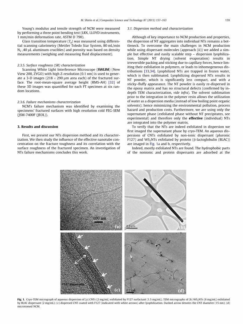
Fig. 1. Cryo-TEM micrograph of aqueous dispersion of (a) CNTs (2 mg/mL) exfoliated byby BLAC dispersant (2 mg/mL); (c) dispersed CNT coated with F127 (indicated with whitmicrotomed NCM.
3.1. Dispersion method and characterization
Although of key importance to NCM production and properties,the dispersion of NT aggregates into individual NTs remains a bot-tleneck. To overcome the main challenges in NCM productionwhile using dispersant molecules (approach (ii)) we added a sim-ple but effective and easily scalable step – dispersion lyophiliza-tion. Simple NT drying (solvent evaporation) results inirreversible packing and sticking due to capillary forces, hence lim-iting their exfoliation in polymers, or leads to inhomogeneous dis-tributions [33,34]. Lyophilized NTs are trapped in frozen water,which is then sublimated. Lyophilizing dispersed NTs results inNT powder, which is significantly less compact, and with asticky–fluffy appearance. The NT powder is easily re-dispersed inthe epoxy matrix and has no structural defects (confirmed by in-depth TEM characterization, vide infra). The solvent sublimationprior to the integration in the polymer resin allows the utilizationof water as a dispersion media (instead of low boiling point organicsolvents); hence minimizing the environmental pollution, processhazard and production costs. Furthermore, we are using only thesupernatant phase (exfoliated phase without NT precipitates, seeexperimental) and therefore only the effective (individual) NTsare integrated into the polymer matrix.
To verify that the NTs are indeed exfoliated in dispersion wefirst imaged the supernatant phase by cryo-TEM. An aqueous dis-persions of CNTs exfoliated by non-ionic dispersant (pluronicF127) and WS2NTs exfoliated by protein (b-lactoglobulin (BLAC))are imaged in Fig. 1a and b, respectively.
Indeed, mostly exfoliated NTs are found. The hydrophobic partsof the nonionic and protein dispersants are adsorbed at the
F127 surfactant (1.5 mg/mL). TEM micrographs of (b) WS2NTs (6 mg/mL) exfoliatede arrows) after lyophilization. Dashed arrow denotes the CNT diameter (15 nm); (d)
Fig. 2. (a) Fracture toughness (FT), NCM’s porosity and epoxy (part A) viscosity(from [37]) as a function of NT vol%. Zone A – increased NT aggregation, Zone B –increased porosity and NT aggregation. (b) FT and surface roughness (SR) as afunction of WS2NT vol%. Inset: linear correlations between SR and FT.
160 M. Shtein et al. / Composites Science and Technology 87 (2013) 157–163
NT–water interface, hence screening the hydrophobic surface fromthe water, whereas the hydrophilic part is extended out into theaqueous phase, providing a steric barrier and preventing NTsaggregation [35]. After lyophilization the NTs remain capped bythe dispersants molecules (the F127 dispersant layer is indicatedby arrows in Fig. 1c). This layer effectively prevents re-aggregationby converting the NT’s surface from hydrophobic to hydrophilicnature. Furthermore, it allows good dispersion in the epoxy matrix[36]. TEM micrograph of the microtomed NCM indicates that a trueNT incorporation into epoxy polymer is obtained (Fig. 1d).
3.2. Determination of the effective concentration
After verifying that the NTs in dispersion are individually exfo-liated we deal with their effective concentration. The non-exfoli-ated aggregates (precipitate) are prone to act as microscopicdefects when present in the matrix. Therefore, the removal (bydecantation) of non-exfoliated NT aggregates and the measure-ment of effective NT concentration are essential. By determiningthe weight of NTs in the precipitate, we can calculate their concen-tration in the supernatant through mass balance. The combinationof TGA and UV–vis techniques yields calibration curves, allowingNT concentration determination by a simple and fast UV–vis spec-troscopy measurement (for details see [30]).
3.3. Fracture toughness (FT) and surface roughness (SR)
The determination of the effective concentration of NTs allowsevaluating of its net influence on the FT of the NCM, without the
side effects of NT aggregates. A combination of in-depth qualitative(SEM) and quantitative (SWLIM) analysis of the fractured NCM sur-faces yields a comprehensive understanding of NT contribution toboth epoxy’s toughening and failure mechanism of the composite.Fracture toughness (FT), porosity, viscosity and surface roughness(SR) as a function of NT vol% are presented in Fig. 2.
3.3.1. Fracture toughness (FT)Specimens with 0.07-0.16 CNT or 0.03-0.23 WS2NT vol% show
significant FT enhancement (Fig. 2a). We achieved record FTenhancement values of 129% and 150% at optimal NTs concentra-tions (0.10 CNT vol% and 0.11 WS2NT vol%, respectively). At theseoptimal NTs concentrations, Young’s modulus (Fig. 3a) and the ten-sile strength (Fig. 3b) were increased by 3.0% for the CNT and by10% for the WS2NT, while the measured glass transition tempera-ture (Fig. 3c) of the NCMs were similar to the neat epoxy (unalteredcross-linking density). The significant enhancement of FT withoutsubstantial change in the other mechanical properties suggestsgenuine nano-reinforcement. Our obtained optimal NTs concentra-tion (�0.1 vol%) is also reported as the rheological percolationthreshold (an abrupt increase in viscosity due to strong physicalinteraction between the NTs, which impedes the polymer chainmobility) experimentally [37–39] and theoretically [40]. Abovethe optimal NTs concentrations, the FT values decrease withincreasing NT content due to increased viscosity (>0.1 vol%,Fig. 2a), which is manifested by small air voids remaining in thehardened matrix. This in turn, results in increased NCM’s porosity(>6 vol%, Fig. 2a, zone B) and NT aggregation (Fig. 2a, zone A + B).The FT enhancement results are quite remarkable for epoxy FTenhancement, and serve as an additional indication of the effec-tiveness of the proposed dispersion method. Previous studies withNT–epoxy system showed only 28% enhancement in FT with pris-tine CNT and 84% enhancement with surface modified (aminated)CNT [25]. Others showed a 26% FT enhancement by mechanical(calendering) method with double-wall CNT [7].
3.3.2. Surface roughness (SR) of the fractured specimenMorphological analysis of the fractured surface of NCM shows
that the neat epoxy (typical specimen is shown in Fig. 4a and c)exhibits smooth, mirror-like surface with SR of 0.06 lm (Fig. 2b),typical of a brittle material [41]. The fractured surfaces of theNT-filled NCM show (Fig. 4b and d) much higher values of SR,namely, 0.52 lm and 3.7 lm at 0.10 CNT vol% and 0.11 WS2NTvol% respectively (Fig. 2b).
During the crack propagation, isolated NTs resist propagationby bifurcation [41,42]. It appears that a typical bifurcation (dashedblack arrows in Fig. 5), starts with isolated, well-dispersed NTs(white arrows in Fig. 5) as clearly demonstrated by in-depth SEManalysis. We believe that the energy dissipation through thesecrack tip bifurcation [43] leads to the dramatic FT increase. Thenumber of bifrucations is quantitatively proportional to SR valuesas characterized by fractured surface imaging. Thus, high SR servesas a good indicator for well-dispersed NT.
3.3.3. SR and FT correlationSurprisingly, while the correlation between FT and SR may
seem clear, it was not previously thoroughly and quantitativelyinvestigated. Recent published studies focus on the qualitative SRanalysis [8,24,43–45] with only few quantitative studies [42,46].We show that FT and SR are in excellent agreement with eachother (Fig. 2b), i.e., the rougher the fractured surface, the higherthe FT of the material. To the best of our knowledge this is the firstreport of such a coherent correlation between these parameters.We believe that the main reasons for such an outstandingcorrelation are the efficient dispersion method and the accurateconcentration determination we developed. These allow us to
Fig. 3. NCM mechanical properties at optimal NT concentrations: (a) Young’s Modulus (b) tensile strength and (c) glass transition temperature.
Fig. 4. SEM micrographs of fractured surfaces (a) plain epoxy and (b) 0.11 vol% WS2NT filled NCM. SWLIM micrographs of fractured surfaces (c) plain epoxy and (d) 0.11 vol%WS2NT filled NCM.
Fig. 5. SEM micrographs of bifurcate propagation path as a result of well-dispersed (a) CNT and (b) WS2NTs. The individual NT and the resulting bifurcation paths areindicated by white and dashed black arrows, respectively.
M. Shtein et al. / Composites Science and Technology 87 (2013) 157–163 161
attribute the FT enhancement to the precisely determined effectiveNT concentration and not to the initial NT concentration thatincludes NT aggregates or unknown NT concentration, thus elimi-nating the complex contribution of NT aggregates on FT and SR.Furthermore, linear regression analysis of the SR–FT slope
(Fig. 2b inset) indicates a higher value for WS2NT-based NCMs(slope = 2.7 lm/(MPa * m0.5)), while only a moderate one for theCNT-based NCMs (slope = 0.33 lm/(MPa * m0.5). This significantdifference may serve as an indication to the NT’s failure mecha-nism (vide infra).
Fig. 6. Schematics presentation of possible failure mechanisms of NTs in polymermatrix: (a?b?c) bridging–pullout and (a?b?d) bridging–fracture mechanism.
Fig. 8. Relative frequency of NT’s initial and protruded lengths in CNT and WS2NTNCMs. N-number of NTs failure events measured.
162 M. Shtein et al. / Composites Science and Technology 87 (2013) 157–163
3.4. Failure mechanisms
According to traditional fracture theory of micro-fibers in poly-mer matrix [47], fiber could fail by two basic mechanisms, i.e. pull-out or fracture. A schematic presentation of pullout (Fig. 6 a?b?c)and fracture (Fig. 6 a?b?d) failure mechanisms are presented.After crack initiation (Fig. 6a), a NT bridges the crack tip (Fig. 6b),and subsequently one side of NT is completely pulled out fromthe polymer matrix (Fig. 6c) or the NT fractures (Fig. 6d).
To identify the failure mechanisms of a given NCM, the frac-tured surfaces of the specimens were examined with high resolu-tion SEM and statistical analysis was implemented on theresulting micrographs. Typical views of failure modes of WS2NT-and CNT-filled NCMs are shown in Fig. 7 a-b and c, respectively.
Typically, the WS2NT-filled NCM fails by a pullout mechanism,as demonstrated in Fig. 7a by protruding WS2NT (right) and a hole(left) formed due to pull-out from the fractured surface. An inter-mediate ‘‘bridging’’ state was identified (Fig. 7b). The bridging WS2-
NT (Fig. 7b, inset) is coated by an epoxy layer indicating enhancedwetting of the dispersing molecules-adsorbed NT surface. TheCNTs present a very different behavior: they are tightly embeddedin the matrix with only short protruding length (Fig. 7c) and a neg-ligible number of detected holes, indicating that most CNTs arefractured and not pulled out during the crack propagation.
To quantify the failure mechanisms of NTs we measured the ini-tial NTs length and their protruded length after fracture. Measure-ments of 680 individual NTs failure events are summarized inFig. 8.
Fig. 7. HR-SEM micrographs of a specimen fractured surface showing (a) pullout failurestate in WS2NT filled NCM. Inset: bridging WS2NT coated with epoxy; and (c) CNTs fille
Statistical analysis of WS2NT failure events shows that the pro-truding length (1.23 ± 0.41 lm) is equal to about half of the initiallength (2.36 ± 0.62 lm), which is a characteristic result of a pulloutfailure mechanism. For the CNT, over 75% of the failure eventsshowed no protruding length (suggesting a clear fracture mecha-nism [27]), while others revealed a significant decrease in protrud-ing CNT’s length (0.09 ± 0.08 lm) as compared to the initial length(1.5 ± 0.41 lm).
The NTs protruding length significantly affects the SR of thefractured specimens. Therefore, at a given concentration of welldispersed NT in the fractured surface, a long protruding length(pulled out WS2NTs) will result in higher SR values compared toshort protruding length (fractured CNTs). In other words, thestrong dependence between SR and FT in the WS2NT system(Fig. 2b-inset) points towards a pullout failure mechanism, whilethe weak dependence in the CNT system to fracture failuremechanism.
It is generally accepted [47] that fillers with stronger interfacialadhesion, tend to be fractured under loading. If the adhesion isweak the NTs are easily pulled out from the matrix. Thus, basedon the statistical analysis of NTs’ failure mechanisms, it is reason-able to assume that CNT–epoxy interfacial adhesion is superiorcompared to WS2NT–epoxy. Further work is expected to shed morelight on the load transfer and failure mechanisms of NT-filled NCM
mechanism: protruding WS2NT (right) and a hole (left); (b) bridging intermediated NCM with very short (<100 nm) protruding length.
M. Shtein et al. / Composites Science and Technology 87 (2013) 157–163 163
by comparing between the adhesion strength of CNT and WS2NTusing direct pullout experiments from an epoxy matrix [48–50].
4. Conclusions
In the present work, we develop novel dispersion and concentra-tion determination methods. These methods enable one not only toeffectively exfoliate individual NTs in polymer matrix, but also toprecisely determine the effective NT concentration. Determinationof NT effective concentration is essential, as it allows evaluation ofits net influence on the FT of the NCM, without the side effects ofNT aggregates. Furthermore, we achieved record FT enhancementvalues of 129% and 150% at optimal NT concentrations (�0.10 NTvol% and 0.11 WS2NT vol%, respectively), without deterioratingother mechanical properties, and for the first time showed a coher-ent quantitative correlation between fracture toughness and frac-tured surface roughness. The optimum concentration is a generalphenomenon; it occurs at roughly the same NT volume fraction(Fig. 2a) for both CNT and WS2NT. Statistical fracture surface analy-sis (by SWLIM and SEM) shows that CNT fail via fracture mechanism,WS2NTs via pullout mechanism and the failure mechanism’s typecould be predicted by the value of the SR–FT slope.
Acknowledgements
The authors thank Jurgen Jopp for critical reading of the manu-script and SWLIM measurements.
References
[1] Tesoro G. Epoxy resins–chemistry and technology, 2nd ed., New York; 1988, p.1288.
[2] Bascom WD, Cottington RL, Jones RL, Peyser P. The fracture of epoxy- andelastomer-modified epoxy polymers in bulk and as adhesives. J Appl Polym Sci1975;19(9):2545–62.
[3] Yu MF, Lourie O, Dyer MJ, Moloni K, Kelly TF, Ruoff RS. Strength and breakingmechanism of multiwalled carbon nanotubes under tensile load. Science2000;287(5453):637–40.
[4] Kaplan-Ashiri I, Cohen SR, Gartsman K, Ivanovskaya V, Heine T, Seifert G, et al.On the mechanical behavior of WS2 nanotubes under axial tension andcompression. Proc Natl Acad Sci USA 2006;103(3):523–8.
[5] Peigney A, Laurent C, Flahaut E, Bacsa RR, Rousset A. Specific surface area ofcarbon nanotubes and bundles of carbon nanotubes. Carbon2001;39(4):507–14.
[6] Geng Y, Liu MY, Li J, Shi XM, Kim JK. Effects of surfactant treatment onmechanical and electrical properties of CNT/epoxy nanocomposites. ComposPart A – Appl Sci Manuf 2008;39(12):1876–83.
[7] Gojny FH, Wichmann MHG, Köpke U, Fiedler B, Schulte K. Carbon nanotube-reinforced epoxy-composites: enhanced stiffness and fracture toughness atlow nanotube content. Compos Sci Technol 2004;64(15):2363–71.
[8] Zohar E, Baruch S, Shneider M, Dodiuk H, Kenig S, Tenne R, et al. The effect ofWS2 nanotubes on the properties of epoxy-based nanocomposites. J Adhes SciTechnol 2011;25(13):1603–17.
[9] Duesberg GS, Burghard M, Muster J, Philipp G, Roth S. Separation of carbonnanotubes by size exclusion chromatography. Chem Commun 1998;3:435–6.
[10] Murphy R, Coleman JN, Cadek M, McCarthy B, Bent M, Drury A, et al. High-yield, nondestructive purification and quantification method for multiwalledcarbon nanotubes. J Phys Chem B 2002;106(12):3087–91.
[11] Weiss V, Thiruvengadathan R, Regev O. Preparation and characterization of acarbon nanotube–lyotropic liquid crystal composite. Langmuir2006;22(3):854–6.
[12] Zheng M, Jagota A, Semke ED, Diner BA, McLean RS, Lustig SR, et al. DNA-assisted dispersion and separation of carbon nanotubes. Nat Mater2003;2(5):338–42.
[13] Tenne R. Advances in the synthesis of inorganic nanotubes and fullerene-likenanoparticles. Angew Chem – Int Edit 2003;42(42):5124–32.
[14] Zhu YQ, Hsu WK, Grobert N, Chang BH, Terrones M, Terrones H, et al.Production of WS2 nanotubes. Chem Mater 2000;12(5):1190–4.
[15] Dror Y, Pyckhout-Hintzen W, Cohen Y. Conformation of polymers dispersingsingle-walled carbon nanotubes in water: a small-angle neutron scatteringstudy. Macromolecules 2005;38(18):7828–36.
[16] Georgakilas V, Kordatos K, Prato M, Guldi DM, Holzinger M, Hirsch A. Organicfunctionalization of carbon nanotubes. J Am Chem Soc 2002;124(5):760–1.
[17] Vigolo B, Pénicaud A, Coulon C, Sauder C, Pailler R, Journet C, et al. Macroscopicfibers and ribbons of oriented carbon nanotubes. Science2000;290(5495):1331–4.
[18] Bandyopadhyaya R, Nativ-Roth E, Regev O, Yerushalmi-Rozen R. Stabilizationof individual carbon nanotubes in aqueous solutions. Nano Lett2001;2(1):25–8.
[19] Nepal D, Geckeler KE. PH-sensitive dispersion and debundling of single-walledcarbon nanotubes: lysozyme as a tool. Small 2006;2(3):406–12.
[20] Chang L, Friedrich K, Ye L, Toro P. Evaluation and visualization of thepercolating networks in multi-wall carbon nanotube/epoxy composites. JMater Sci 2009;44(15):4003–12.
[21] Guadagno L, Vertuccio L, Sorrentino A, Raimondo M, Naddeo C, Vittoria V, et al.Mechanical and barrier properties of epoxy resin filled with multi-walledcarbon nanotubes. Carbon 2009;47(10):2419–30.
[22] Shneider M, Dodiuk H, Kenig S, Tenne R. The effect of tungsten sulfidefullerene-like nanoparticles on the toughness of epoxy adhesives. J Adhes SciTechnol 2010;24(6):1083–95.
[23] Lu KL, Lago RM, Chen YK, Green MLH, Harris PJF, Tsang SC. Mechanical damageof carbon nanotubes by ultrasound. Carbon 1996;34(6):814–6.
[24] Gojny FH, Wichmann MHG, Fiedler B, Schulte K. Influence of different carbonnanotubes on the mechanical properties of epoxy matrix composites – acomparative study. Compos Sci Technol 2005;65(15–16):2300–13.
[25] Lachman N, Daniel Wagner H. Correlation between interfacial molecularstructure and mechanics in CNT/epoxy nano-composites. Compos Part A: ApplSci Manuf 2010;41(9):1093–8.
[26] Tang L-C, Zhang H, Han J-H, Wu X-P, Zhang Z. Fracture mechanisms of epoxyfilled with ozone functionalized multi-wall carbon nanotubes. Compos SciTechnol 2011;72(1):7–13.
[27] Tang L-C, Zhang H, Wu X-P, Zhang Z. A novel failure analysis of multi-walledcarbon nanotubes in epoxy matrix. Polymer 2011;52(9):2070–4.
[28] Fiedler B, Gojny FH, Wichmann MHG, Nolte MCM, Schulte K. Fundamentalaspects of nano-reinforced composites. Compos Sci Technol2006;66(16):3115–25.
[29] Qian D, Dickey EC. In situ transmission electron microscopy studies ofpolymer–carbon nanotube composite deformation. J Microsc2001;204(1):39–45.
[30] Shtein M, Pri-bar I, Regev O. A simple solution for the determination of pristinecarbon nanotube concentration. Analyst 2013;138(5):1490–6.
[31] Talmon Y. Transmission electron microscopy of complex fluids: the state of theart. Berichte der Bunsengesellschaft für physikalische Chemie1996;100(3):364–72.
[33] Moniruzzaman M, Winey KI. Polymer nanocomposites containing carbonnanotubes. Macromolecules 2006;39(16):5194–205.
[34] Grady BP. Recent developments concerning the dispersion of carbonnanotubes in polymers. Macromol Rapid Commun 2010;31(3):247–57.
[35] Szleifer I, Yerushalmi-Rozen R. Polymers and carbon nanotubes –dimensionality, interactions and nanotechnology. Polymer2005;46(19):7803–18.
[36] Zhang W, Lu W, Wang S, Zhou H. Influence of dipole interactions onmechanical behavior of modified epoxy resins. Polym J 2003;35(6):470.
[37] Bauhofer W, Kovacs JZ. A review and analysis of electrical percolation incarbon nanotube polymer composites. Compos Sci Technol2009;69(10):1486–98.
[38] Penu C, Hu G-H, Fernandez A, Marchal P, Choplin L. Rheological and electricalpercolation thresholds of carbon nanotube/polymer nanocomposites. PolymEng Sci 2012;52(10):2173–81.
[39] Rahatekar SS, Koziol KKK, Butler SA, Elliott JA, Shaffer MSP, Mackley MR, et al.Optical microstructure and viscosity enhancement for an epoxy resin matrixcontaining multiwall carbon nanotubes. J Rheol 2006;50(5):599–610.
[40] Balberg I, Anderson CH, Alexander S, Wagner N. Excluded volume and itsrelation to the onset of percolation. Phys Rev B 1984;30(7):3933–43.
[41] Zhou Y, Jeelani MI, Jeelani S. Development of photo micro-graph method tocharacterize dispersion of CNT in epoxy. Mater Sci Eng: A 2009;506(1–2):39–44.
[42] Kinloch A, Taylor A. The mechanical properties and fracture behaviour ofepoxy–inorganic micro- and nano-composites. J Mater Sci2006;41(11):3271–97.
[43] Ma PC, Kim J-K, Tang BZ. Effects of silane functionalization on the properties ofcarbon nanotube/epoxy nanocomposites. Compos Sci Technol2007;67(14):2965–72.
[44] Thostenson ET, Chou T-W. Processing-structure-multi-functional propertyrelationship in carbon nanotube/epoxy composites. Carbon2006;44(14):3022–9.
[45] Kim BC, Park SW, Lee DG. Fracture toughness of the nano-particle reinforcedepoxy composite. Compos Struct 2008;86(1–3):69–77.
[46] Miyagawa H, Drzal LT. The effect of chemical modification on the fracturetoughness of montmorillonite clay/epoxy nanocomposites. J Adhes Sci Technol2004;18(13):1571–88.
[47] Hull D, Clyne TW. An introduction to composite materials. CambridgeUniversity Press; 1996 (Aug 13).
[48] Barber AH, Cohen SR, Wagner HD. Measurement of carbon nanotube–polymerinterfacial strength. Appl Phys Lett 2003;82(23):4140–2.
[49] Barber AH, Cohen SR, Kenig S, Wagner HD. Interfacial fracture energymeasurements for multi-walled carbon nanotubes pulled from a polymermatrix. Compos Sci Technol 2004;64(15):2283–9.
[50] Barber AH, Cohen SR, Eitan A, Schadler LS, Wagner HD. Fracture transitions at acarbon-nanotube/polymer interface. Adv Mater 2006;18(1):83–7.