FRACTURE CONTROL PRACTICES FOR METAL STRUCTURES H.l. McHenry ^ S.T. Rolfe ^ ^ Fracture and Deformation Division National Measurement Laboratory National Bureau of Standards Boulder, Colorado 803.03 2 University of Kansas Civil Engineering Department Lawrence, Kansas 66044 Sponsored by; David Taylor Naval Ship Research & Development Center Annapolis, MD 21402 QC 100 .U56 79-1623 1980 January 1980
Transcript
FRACTURE CONTROL PRACTICES FOR METAL STRUCTURES
H.l. McHenry ^
S.T. Rolfe^
^ Fracture and Deformation Division
National Measurement Laboratory
National Bureau of Standards
Boulder, Colorado 803.03
2University of Kansas
Civil Engineering Department
Lawrence, Kansas 66044
Sponsored by;
David Taylor Naval Ship Research & Development Center
Annapolis, MD 21402
QC100
.U56
79-1623
1980January 1980
NBSIR 79-1623
FRACTURE CONTROL PRACTICES FOR METAL STRUCTURES
H.l. McHenry ^
S.T. Rolfe^
Fracture and Deformation Division
National Measurement Laboratory
National Bureau of Standards
Boulder, Colorado 80303
2University of Kansas
Civil Engineering Department
Lawrence, Kansas 66044
Sponsored by:
David Taylor Naval Ship Research & Development Center
Annapolis, MD 21402
January 1980
U.S. DEPARTMENT OF COMMERCE, Philip M. Klutznick, Secretary
Luther H. Hodges, Jr., Deputy Secretary
Jordan J. Baruch, Assistant Secretary for Science and Technology
NATIONAL BUREAU OF STANDARDS, Ernest Ambler, Director
TABLE OF CONTENTS
Page
ADMINISTRATIVE INFORMATION 1
1. INTRODUCTION - 1
2. ELEMENTS OF FRACTURE CONTROL 2
2.1. Structural Design Conditions 2
2.1.1. Design Life 3
2.1.2. Loads 3
2.1.3. Environment 3
2.1.4. Initial Damage Assumption 3
2.1.5. Safety Factors 3
2.2. Materials 4
2.2.1. Selection 4
2.2.2. Properties 4
2.2.3. Specifications 4
2.3. Design 5
2.3.1. Design for Fracture Control - 5
2.3.2. Standard Details 5
2.3.3. Joining Practices 5
2.4. Analysis 6
2.4.1. Stress Analysis 6
2.4.2. Fatigue Analysis 6
2.4.3. Fracture Mechanics Analysis 6
2.4.4. Fail-Safe Analysis 6
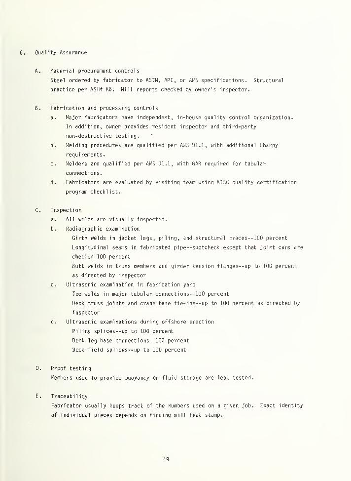
2.5. Quality Assurance 7
2.5.1. Material Procurement Controls 7
2.5.2. Fabrication and Processing Controls 7
2.5.3. Inspection 7
2.5.4. Proof Testing 7
2.5.5. Traceability 8
2.5.6. Verification Testing 8
2.6 In-Service Controls 8
2.6.1. In-Service Monitoring 8
2.6.2. Periodic Inspection 8
2.6.3. Maintenance 8
2.6.4. Repair 9
3. THE CODE APPROACH TO FRACTURE CONTROL 9
3.1. Structural Design Conditions 9
3.1.1. Design Life 10
3.1.2. Loads 10
3.1.3. Environment 10
3.1.4. Assumed Initial Damage 10
3.1.5. Safety Factors 11
3.2 Materials 11
3.2.1. Specifications 11
3.2.2. Properties 12
3.2.3. Toughness Requirements 13
3.3. Design and Analysis 14
3.3.1. Design for Fracture Control 14
3.3.2. Standard Details 15
3.3.3. Analyses 15
3.3.4. Fatigue Control 16
3.4. Quality Assurance 17
3.4.1 Material procurement controls 17
3.4.2 Fabrication and processing controls 17
3.4.3 Inspection 18
3.4.4 Verification testing 18
i i i
contents (continued) Page
3.5. In-Service Controls 19
3.5.1. Periodic inspection 19
3.5.2. Maintenance and repair 20
4. THE PERFORMANCE SPECIFICATION APPROACH TO FRACTURE CONTROL— 20
4.1. Structural Design Condit'ons 20
4.2. Materials 21
4.3. Design and Analysis 21
4.4. Quality Assurance 22
4.5. In-Service Controls 23
5. FRACTURE CONTROL CONCEPTS FOR NAVAL SYSTEMS 23
5.1. Steel Toughness Requirements 23
5.1.1. The strain rate shift 23
5.1.2. Metallurgical controls 24
5.1.3. Toughness saturation 24
5.2. Weld Quality Standards 24
5.2.1. Fitness-for-service 25
5.2.2. Assessment of flaws detected during in-service
inspection 25
5.3. Aerospace Practices for High Performance Structures 26
5.3.1. Loads 26
5.3.2. Full-scale testing 26
5.3.3. Fracture critical parts 27
6. SUMMARY COMMENTS 28
7. ABBREVIATIONS 29
APPENDIX 31
MERCHANT SHIPS 32
LNG SHIPS - CONTAINMENT SYSTEMS - 36
FIXED OFFSHORE STRUCTURES 44
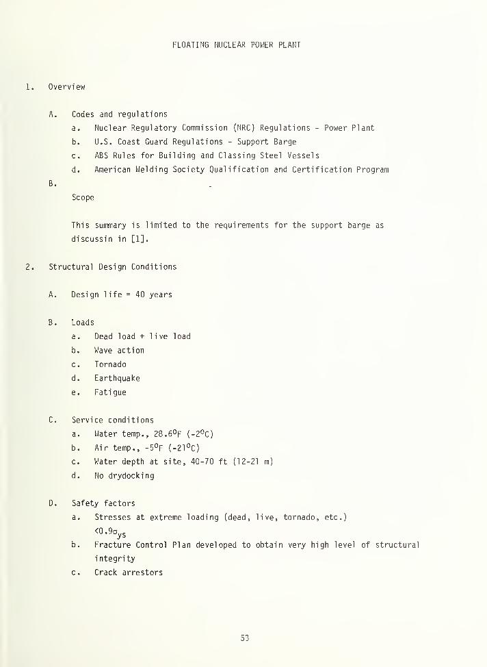
FLOATING NUCLEAR POWER PLANT 53
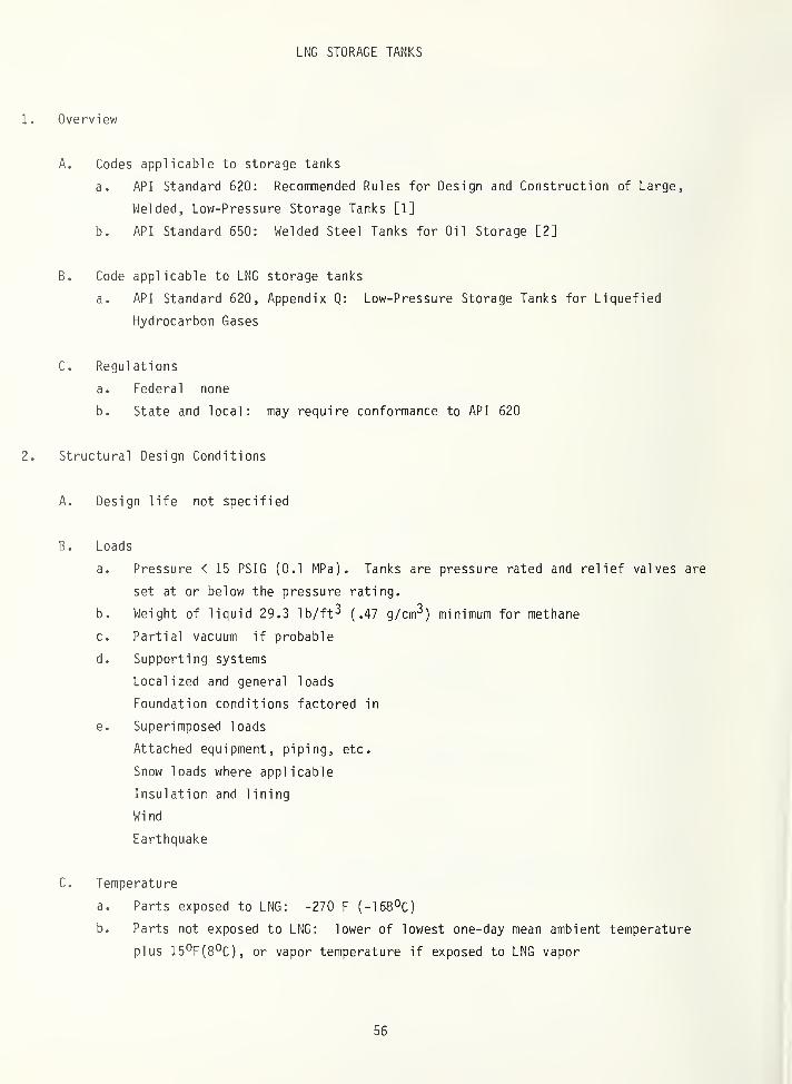
LNG STORAGE TANKS 56
STEEL BRIDGES 61
LARGE ROTATING EQUIPMENT 65
PRESSURE VESSELS 68
NUCLEAR PRESSURE VESSELS 72
GAS AND OIL PIPELINES 75
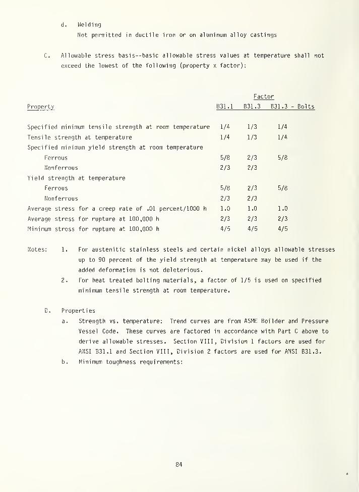
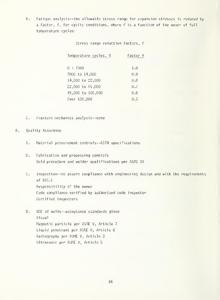
PRESSURE PIPING— POWER AND CHEMICAL INDUSTRIES 82
USAF AIRCRAFT 88
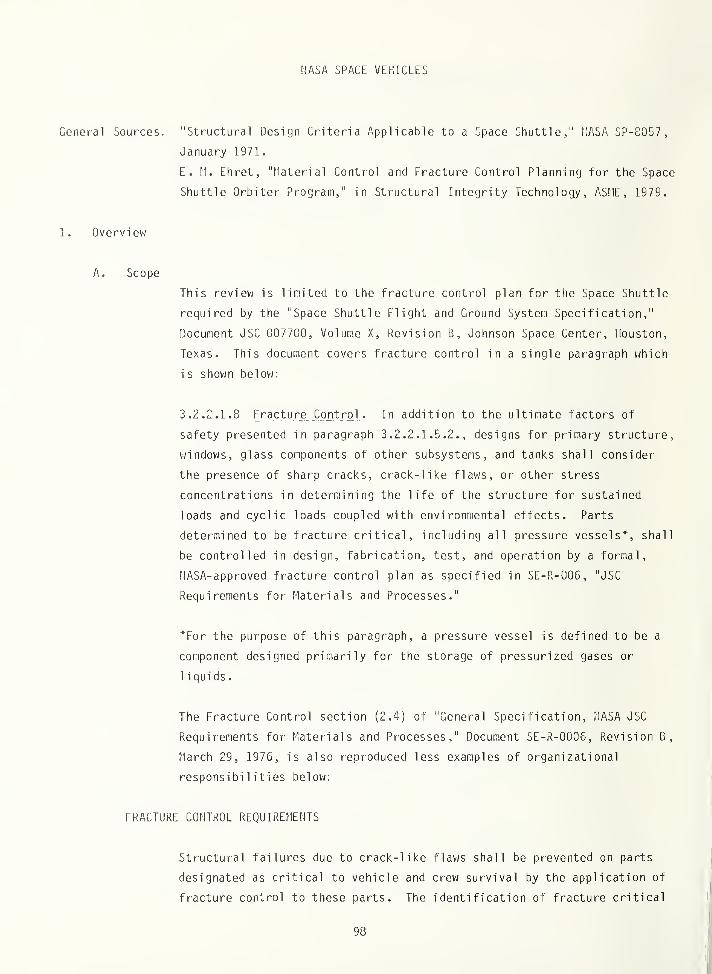
NASA SPACE VEHICLES 98
i V
LIST OF FIGURES
Page
1061. The Effect of Strain Rate on the Fracture Toughness of
a Structural Steel
2. Critical Crack Length as a Function of Charpy V-Notch 107
Toughness for a Specific Type of Size of Line Pipe
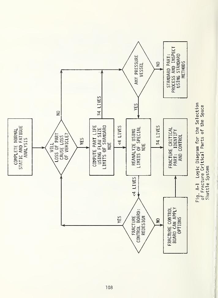
A-1 Logic Diagram for the Selection of Fracture Critical 108
Parts of the Space Shuttle System
V
FRACTURE CONTROL PRACTICES FOR
METAL STRUCTURES
H. I. McHenry
S. T. Rolfe
Fracture control practices are the engineering procedures and requirements thatcontribute to the prevention of fracture in metal structures. These practicesare identified as the elements of fracture control and each element is definedand described. The systematic application of these practices to the preventionof fracture in a particular structure is accomplished by either the code approachor the performance specification approach to fracture control. In these two
approaches, the consideration given to each of the elements of fracture control is
discussed and illustrated with examples for specific types of structures. Selectedpractices that may be of use in Naval systems are discussed. An Appendix containsdetailed summaries of the fracture control practices used in each of thirteenclasses of metal structures, including ships, offshore structures, bridges, cryo-genic tanks, pressure vessels, piping, power generation equipment, and aerospacestructures.
Note on Units: Duplicate units are used throughout this document. SI units appearfirst followed by English units except when quotations from codes and specificationsare given. In that case the first unit is a direct quotation and the second is a
conversion
.
ADMINISTRATIVE INFORMATION
This project was sponsored by the Naval Sea Systems Command (SEA 05R) under Program
Element 62761N, Task Area SF54-591-506 . The program manager is Dr. H. H. Vanderveldt
(SEA 05R). The project monitor was John P. Gudas of the David W. Taylor Naval Ship Research
and Development Center (Code 2814).
1. INTRODUCTION
In the fall of 1977, the Naval Sea Systems Command started a program entitled "Fracture
Control Technology for Ships and Submarines". The initial tasks included the identification
of Navy fracture control requirements and an assessment of fracture control practices used by
U.S and foreign industries. As part of this program, NBS was requested to review fracture
control practices used by American industry and by government agencies other than the Navy
and to identify practices that may be useful to the Navy.
The approach used in this study was first to identify and define the elements of frac-
ture control, and then to prepare detailed summaries of the fracture control practices used
for thirteen classes of metal structures. Concurrently, Navy personnel were reviewing Navy
practices and requirements relative to fracture control. Discussions with the Navy investi-
gators led to the identification of fracture control concepts that are potentially useful to
the Navy.
The report consists of the review of fracture control elements and approaches, and the
identification of innovative and cost-effective fracture control concepts that merit consider-
ation for Naval systems. The detailed summaries of fracture control practices used for thir-
teen types of structures are presented in the Appendix.
2. ELEMENTS OF FRACTURE CONTROL
The objective in design of large complex structures such as ships, bridges, pressure
vessels, aircraft, etc. is to optimize the desired performance requirements relative to cost
considerations (i.e., the overall cost of materials, design, fabrication, and operation) so
that the probabil ityland economic consequences)of failure are low. To achieve these objec-
tives, engineers make predictions of service loads and conditions, calculate stresses in
various structural members resulting from these loads and service conditions, and size the
members such that the stresses are limited to values below the critical stresses for the
potential failure modes of the structure, i.e., yielding, buckling, fatigue, creep, and
brittle fracture.
The prevention of brittle fracture is an important consideration because of the sudden
and uncontrolled nature of such failures. Experience gained from service failures of many
engineering structures indicates that most brittle fractures are initiated by small flaws
that grow, as cracks, to a critical size during service. Accordingly, there are three parts
to the fracture problem: (1) The initial flaw size, (2) crack growth, and (3) crack tolerance.
The initial flaw size is a function of material and weld quality, the workmanship during
fabrication, and the inspection and quality control. The crack-growth behavior is controlled
by the cyclic stress history, the thermal and chemical environment, and the design detail.
The crack tolerance is governed by the material toughness, the crack size, and the maximum
stress level.
A complete understanding of all these factors is obviously not possible for a complex
structure. Thus, to assure safety, it is necessary to devise a plan to limit the uncertain-
ties. Such a plan is a fracture control plan and consists of the systematic consideration
of the numerous elements of the fracture problem. The elements of fracture control are all
of the factors that must be considered during design, fabrication, and operation of a struc-
ture to assure satisfactory fracture resistance of the structure during its intended service
life. The various elements of fracture control are listed and defined in this section.
2.1. Structural Design Conditions
The structural design criteria are the operational and performance standards against
which the expected (or actual) behavior of the structure can be judged. They are based on
the specified operating conditions that the structure must be designed to tolerate, and the
analysis assumptions and safety factors used in design. Operating conditions relevant to
fracture control include the design service life, the anticipated service load history, and
2
the thermal and chemical environment. Analysis assumptions may include consideration of
failed members, preexisting flaws, superimposed loads, and methods of combining stresses.
Safety factors on loads or on material properties may be used to account for uncertainties
in the loads and material properties.
2.1.1. Design life
Design life is the specific number of years of service (e.g., 20 years) or application
of loads (e.g., 2,000,000 cycles) that a structure must withstand. A distinction should be
made between total design life (useful service) and intermediate design life (time for
replacement of critical parts or membe'rs to extend the total design life of the structure).
2.1.2. Loads
Loads are all the forces that the structure must withstand throughout its life, such as
The environment in which the structure must perform is the anticipated thermal and
chemical exposure. Temperature extremes, time at temperature, and number of thermal cycles
should be used to account for strength reductions due to thermal exposure and to analyze for
creep and thermal fatigue. The chemical environment (e.g., sea water, fuel, air, etc.)
should also be characterized in terms of duration and repetitions of exposure. For
environmental considerations, the load vs. time profile also becomes important to properly
account for environmentally enhanced fatigue crack growth.
2.1.4. Initial damage assumption
Flaws, deformation, the failure of members, etc. should be considered during design. In
certain design codes, the designer is required to account for the possibility of flaws and to
conduct a fracture mechanics analysis to insure the satisfactory behavior of the flawed
structure.
2.1.5. Safety factors
Limit criteria (e.g., yield strength, Kj^, etc.) generally are reduced by factors,
or applied loads increased by factors, to reach an allowable working stress that accounts
for unexpected variations in loads or material properties. These factors are called safety
factors. Increasing the factor of safety for a particular mode of failure, reduces the
likelihood of failure by that particular mode.
3
Probabilistic analysis is an emerging design concept that can be used instead of safety
factors.2.2.
Materials
The fracture resistance of a structure is strongly dependent on the materials of
construction. Controls on material procurement and subsequent processing (heat treatment,
welding, etc.) must be implemented such that the material in the as-fabricated structure
retains the properties assumed in design.
2.2.1. Selection
Often, the materials for a particular class of structures are specified by codes, and
the material selection process is automatic. That is, materials that have been used
successfully in the past are selected for similar applications. However, for new systems or
applications, material selection actually depends on an optimization of strength, ductility,
toughness, fabricabi 1 i ty, fatigue, environmental, and cost factors. Thus, material selection
should be based on an understanding of the material response to all anticipated service
loadings and environments.
2.2.2. Properties
Material properties used in design are generally based on the minimum values required in
the material procurement specification such as yield strength, tensile strength, and in some
cases, toughness properties such as CVN, NDT, or Alternatively, data compilations
such as MIL Handbook-V may be used as the source of statistically derived property values.
Properties such as fatigue behavior may be included in the code or code-approved handbooks.
Code-approved procedures, or in some cases, code-body approvals, generally are required
to develop properties of materials needed for design but not available from approved sources.
2.2.3. Specifications
Material procurement specifications are used to provide assurance that the materials of
construction do not have properties inferior to those assumed in design. Specifications
generally are required for each material and product form. These documents specify the mini-
mum acceptable values for the tensile properties and, in some cases, fracture properties.
Requirements may also be established for melting and primary processing (such as in ABS*
specifications), heat treatment, chemical composition, ultrasonic quality, and dimensional
tolerances. Quality assurance provisions, testing procedures, and reporting requirements
may be stipulated.
*Abbreviations defined in Section 7,
4
Material processing specifications nay be required for all processing operations that
nay alter the as-fabricated properties of the material. Examples are specifications for heat
treatment, v/elding, and electroplating. These documents specify requirements for equipment
control, processing procedures, acceptance standards, quality assurance provisions, and
workmanship. Where applicable, tests may be required to measure mechanical properties,
chemical composition, surface condition, and dimensional tolerances. Procedures are defined
for surface preparation, rework and repair, temperature control, etc. Applicable testing
procedures, subcontractor provisions, and reporting requirements may be stipulated.
2.3 Design
Design is the overall process of proportioning and arranging members into a structural
configuration that will perform the intended functions under the specified design conditions.
As part of a comprehensive fracture control plan, design responsibilities include the
following; a) Minimize the probability of structural failure by using damage-tolerant design
concepts and materials, b) reduce the incidence of fatigue cracking and corrosion problems
by careful attention to design detail, and c) provide adequate accessibility for inspection
and repair.
2.3.1. Design for fracture control
Certain codes require that damage in the as-fabricated structure or damage that occurs
during service be considered during the initial design process. The methods most commonly
used are the safe life and fail-safe approaches. The safe-life approach requires that a flaw
will not grow to critical size during service due to the anticipated loads and environment.
The fail-safe approach requires that the structure remaining after failure of any given member
will not fail within a period of service sufficient to detect and repair the failed member.
2.3.2. Standard details
Standard details are those that are known to give satisfactory performance in other
structures. Many codes stipulate that the standard details described in the code be used
where applicable. For example, certain welded connections such as ground butt welds have
better fatigue lives than partial -penetrati on butt v/elds- Hence these standard details can
be specified with some assurance of the level of performance.
2.3.3. Joining practices
The design should require qualified joining practices to assure satisfactory reliability
in welded and mechanically fastened joints. Most codes require qualification of each welding
procedure, i.e., for each material (or class of materials), welding process, position, and
thickness range. Similarly, codes for bolted or riveted structures such as aircraft may
stipulate hole preparation and fastener installation procedures that assure satisfactory
fatigue resistance.
5
2.4. Analysis
Analysis is the analytical evaluation of the design to determine the distribution and
magnitude of the stresses and to determine if the design conforms to the structural design
criteria relative to strength, deformation, fatigue, fracture, and safety.
2.4.1. Stress analysis
Stress analysis consists of the analytic determination of the stresses and deformations
resulting from the external loads and temperature imposed on the structure. The results are
compared v/ith the specified design criteria to determine margins of safety. Design itera-
tions are required until there are adequate margins of safety throughout the structure.
2.4.2. Fatigue analysis
Fatigue analysis is the assessment of the expected behavior of the structure to assure
that fatigue failure will not occur within the specified service life due to application of
the anticipated loads. This may be accomplished by reducing the stresses below a level
specified in the code for fatigue critical details (as is the case for bridges) or by
calculating the fatigue damage in the structure using semi empi ri cal methods. The calculated
fatigue damage is compared with the specified design criteria to determine if the require-
ments are met. If the fatigue damage is too high, design iterations are required until the
stress levels throughout the structure are sufficiently low to meet the fatigue requirements.
2.4.3. Fracture mechanics analysis
Fracture mechanics analysis is the analytical determination of the influence of loading,
crack size, and structural geometry on the fracture resistance of materials containing cracks.
When applied to design, the objective of the fracture mechanics analysis is to limit operating
stresses such that a flaw of a specified initial size located anywhere in the structure will
not grow to critical size during the service life of the structure. Service life for a
given location is calculated on the basis of the specified initial flaw size, a stress anal-
ysis of the structure for the location in question, and experimental data describing the crack
growth and fracture behavior of the material used. Fracture mechanics parameters are used
to compare the stress field ahead of a crack (Kj) with the critical material toughness
(Kj^), i.e., analogous to comparing a design stress (c) with a limiting stress
(ays).
2.4.4. Fail-safe analysis
Fail-safe analysis is the stress analysis of the structure with one or more elements
failed as specified in the criteria. Dynamic release of energy during failure of the element(s)
6
must be taken into account. The stresses in the remaining structure must be sufficiently
low to meet the design criteria for residual strength and fatigue life.
2.5 Quality Assurance
Quality assurance is the system of controls used to ensure that the as-fabricated struc-
ture conforms to the code requirements.
2.5.1. Material procurement controls
Receiving inspection verifies that the raw material meets the requirements of the
applicable procurement specifications. This is accomplished by reviewing the records supplied
by the vendor and, where applicable, by conducting acceptance tests. All material should bo
clearly marked and allocated such that the correct material is used throughout the structure.
2.5.2. Fabrication and processing controls
Production processing and fabrication should be conducted by qualified personnel in
accordance with documented work instructions, using adequate equipment.
Testing requirements invoked by the processing specification should be performed as
required on a timely basis. Processing variables such as temperature, time, welding para-
meters, etc. should be monitored using calibrated equipment, and the variables should bo
controlled within acceptable ranges.
2.5.3. Inspection
Inspection should insure that the structure conforms to the material, dimensional, and
installation requirements of the structural drawings and that defects which could cause
premature failure are not present in the raw material or the as-fabricated structure.
Inspection consists of the dimensional checks, nondestructive evaluation of specified areas
such as the welds, and in some cases, destructive tests to verify conformance to standards
generally specified on the drawing.
2.5.4. Proof testing
Some structures, e.g., pressure vessels, pipes, etc. are loaded to stress levels greater
than the anticipated service loads to verify structural integrity. This loading, generally
hydrostatic, is called proof testing, and is intended to bo nondestructive.
7
2.5.5.Traceability
Traceability refers to the ability to trace the history of the materials of construction
through records indicating original manufacturing procedures, test results, fabrication
sequence, etc. These records may be used to predict the remaining life of a structure, to
help establish the reasons for any failures, and to determine if other similar structures
have a potential problem.
2.5.6. Verification testing
Accelerated total-service-life testing of completed documents or entire structures is
referred to as verification testing. It usually is only done v/hen there are numerous ident-
ical structures such as small pressure vessels, automobiles, insulation panels, etc. in which
actual service loads can be applied and the behavior verified by testing to failure.
2.6. In-Service Controls
Once the structure is put into service several controls should be implemented to prevent
fracture. These controls include: Monitoring the severity of service usage, periodic
inspection and maintenance, and approved repair procedures.
2.6.1. In-service monitoring
For certain structures, the time history of loads (and sometimes temperature) should be
recorded to verify that the load history assumed in design is at least as severe as the actual
load history. This is accomplished for USAF aircraft through the loads/environment spectra
survey and for commercial aircraft by instrumenting representative aircraft with flight load
recorders which monitor the principal load parameters, i.e., velocity, acceleration, and
altitude. In other structures (such as nuclear pressure vessels), time, temperature, and
pressure recorders are used to monitor service usage.
2.6.2. Periodic inspection
Many structures, particularly those susceptible to extensive fatigue and/or corrosion,
are subjected to periodic inspection to assure that structural damage is detected prior to
fai lure.
2.6.3.
Maintenance
A maintenance plan should be developed for many classes of structures to prevent damage
due to wear and corrosion that may enhance fatigue damage or otherwise lead to premature
fai lure.
8
2.6.4. Repair
When structural damage is detected, approved repair procedures should be used to assure
the structural integrity of the repaired region. In general, the repair procedure should
adhere to the code requirements governing materials and processes, such as welding consum-
mables and post-weld thermal treatments.
3. THE CODE APPROACH TO FRACTURE CONTROL
Current approaches to fracture control vary widely from industry to industry.
Consideration of the numerous practices’ summarized in the Appendix reveals two general
approaches: 1) The design and fabrication codes, and 2) performance specifications. In the
code approach to fracture control, the design and fabrication of a particular structure
conform to a set of rules established for the general class of structures that includes the
particular structure, e.g., bridges, pressure vessels, and ships. The performance specifi-
cation approach, discussed in section 4 is applicable to high performance structures where
the inefficiencies associated with general rules cannot be tolerated, e.g., airplanes and
spacecraft.
The code approach to fracture control is used for general classes of structures where
loading modes, design procedures, fabrication methods, and inspection procedures are fairly
uniform. A code is a set of rules established for a general class of structures by commit-
tees of interested and knowledgeable engineers. Examples are the ABS Rules for Shipbuilding,
the ASME Boiler and Pressure Vessel Code, and the AASHTO Standard Specifications for Highway
Bridges. Sometimes these codes, combinations of code segments, and/or additional rules are
incorporated into Federal regulations, e.g., the U.S. Coast Guard regulations for ship-
building or the Office of Pipeline Safety Operations regulations for pipeline construction.
Each of the elements of fracture control is considered in the context of the code
approach in the following subsections. The examples used to illustrate specific practices
are taken from the detailed summaries of fracture control practices presented in the Appendix.
3.1. Structural Design Conditions
The design conditions, analysis assumptions, and safety factors on material properties
used as the basis for structural design criteria vary from code to code depending on the
severity of the design conditions, the scope of the structural analysis, and the complexity
of the design. Variations from structure to structure within a code class are accounted for
by stating the design and analysis requirements in general terms. For example, the code may
require consideration of loads due to earthquakes, a negligible factor for most structures
but a primary requirement for others.
9
3.1.1.Design 1 i fc
Design life is not a specific requirement in codes. Generally the procurement
specification for a code structure specifies the design life. The number of fatigue cycles
and the corrosion allowance are related to design life and accounted for by code rules.
3.1.2. Loads
Loads are conservatively estimated in the code approach. For many classes of structures,
there is a dominant load source, e.g., internal pressure for pressure vessels and piping and
centrifugal forces for steam turbine rotors. In more complex structures, the loads are
estimated on a worst-case basis. For example, to estimate bridge loads, it is assumed that
each lane is occupied by a line of trucks that extends over the complete span. The most
approximate treatment of loads is the case of merchant ships where design is based on scaling
of known proportions of structural sections rather than on specific loadings. Superimposed
on the primary loads are thermal stresses, dead loads due to structural weight and, where
applicable, the loads duo to wind, earthquakes, ice, and snow.
3.1.3. Environment
The anticipated service environment is an important consideration in the design of many
structures. The minimum design temperature is particularly important for the selection of
steels with satisfactory toughness. The API 620 code for storage tanks specifies minimum
temperatures as a function of location. Elevated temperature exposure must be considered
because of reduced strength and creep as temperature and time at temperature increase.
Chemical environment is considered because of corrosion in containers for chemicals and for
structures that operate in adverse environments such as offshore structures.
3.1.4. Assumed initial damage
Initial damage assumptions are not generally required in codes. For example, the AASHTO
bridge code simply requires that all injurious defects be removed. Weld defects are permit-
ted within acceptance limits defined by the codes, but the defects are sufficiently small so
that they need not be considered in the design. In view of actual service experience with
large welded structures, this assumption may not be realistic.
Structures where initial damage is assumed include LHC ships and cargo tanks and gas
pipelines. LIIC ships are required to have a double bottom, double side shells, and trans-
verse bulkheads to localize hull damage to a portion of the ship. LNC containment systems
arc designed to tolerate failure of the primary barrier either through the use of a secondary
barrier or through a 1 eak-before-break approach that has been approved for a specific pressure
vessel design. An initial damage assumption is not explicitly required for gas pipelines but
10
toughness requirements for the line pipe are generally established by the owner company such
that the material can arrest a running through-thickness crack.
3.1.5. Safety factors
Safety factors in codes are generally applied to material properties to arrive at
acceptable design stress levels. For example, a factor of safety of 3 on burst strength is
required in the AIISI B31.1 and B31.3 piping codes, ASME Pressure Vessel Code Section VIII
Division 2, and the API G20 Storage Tank Code. This is achieved by specifying that the
allowable stress in tension is the lesser of 1/3 of the ultimate strength or 2/3 of the yield
strength. Additional factors may be required for castings and weldments. In certain codes,
factors may depend on steel quality, type’of welding, degree of inspection, and production
form. For example, in API 620 a factor is applied to allowable stress that depends on steel
quality. A factor of 1 on pressure vessel steel, and a factor of .92 on structural steel.
The magnitude of the safety factor varies with the scope of the structural analysis,
the complexity of the design, and the possible consequences of failure. For pressurized com-
ponents, some factors on burst strength are. 4 for ASME Section VIII, Division 1 Pressure
Vessels; 3 for ASME Section VIII, Division 2 Pressure Vessels which require a more thorough
analysis and inspection than Division 1 vessels, and approximately 2 (allowable stress is
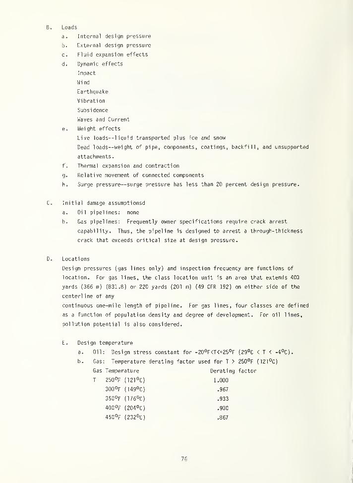
72 percent of the yield strength) on oil pipelines. For gas transmission pipelines, the
allowable stresses are based on the specified minimum yield strength reduced by factors that
range from 0.4 to 0.72 depending on the population density and degree of development in the
vicinity of the pipeline, i.e., stress levels are reduced as the consequences of failure
are increased.
3.2. Materials
In the code approach to fracture control, materials that have been used successfully for
years in similar structures or that have undergone extensive testing generally are the only
ones used. Before new materials can be specified for structures that are designed according
to codes, the code writing bodies must be satisfied (on the basis of material and structural
tests) that these materials will indeed perform satisfactorily.
3.2.1. Specifications
Materials of construction must conform to the requirements of material specifications
listed in the applicable code. In general, unlisted materials may bo used providing the
material is certified to meet all the requirements of a listed material specification, and
its use is approved by either the cognizant code committee (e.g., ASME Pressure Vessel Code)
or by the purchaser (e.g., API 620 Storage Tank Code). Materials are listed by specification
and by grade, i.e., not all grades for a given specification may be used. Usage is further
restricted by notes to avoid improper application of the material.
11
ASTM material specifications are used in many of the codes, including the ANSI B31 pip-
ing codes, the API 620 storage tank code, and the AASHTO bridge code. ASME material
specifications are used in the ASME Boiler and Pressure Vessel Code. The ASME and ASTM
specifications are often related and carry similar numbers, e.g., ASME SA-240 specification
for stainless steels is similar to ASTM A 240. Other material specifications include the
ABS ship steels, and the API specifications for steel line pipe.
Many of the ASTM and ASME material specifications are for product types and cover many
grades. For example, ASTM A 240 is the Standard Specification for Heat-Resisting Chromium
and Chromium-Nickel Stainless Steel Plate, Sheet, and Strip for Fusion Uelded Unfired
Pressure Vessels. It includes many types of stainless steel suitable for this application.
Wherever possible, types are designated by numbers conforming to grade specifications put
out by other organizations. In the case of A 240, grades are specified by the AISI desig-
nation such as 302, 304, 304L, etc. Grades not covered by the AISI designation system are
given ASTM-desi gnati ons such as XM17, a nitrogen-strengthened CK-Ni-Mn stainless steel.
Similarly, ASTM A 131 is the standard specification for structural steel for ships and the
grade designations are related to the ABS grades of ship steel.
Some codes, such as the API RP 2A code for offshore structures, use many types of mate-
rial specifications. The approved materials list in API RP 2A includes Canadian (CSA),
German (DIN), British (BS), and International (ISO) designations and several types of Amer-
ican Speci f i cati ons--ASTM, API, and ABS.
3.2.2. Properties
The material specifications specify the minimum tensile properties that are used as the
basis for determining allowable stress values. Usually minimum values for tensile strength,
0.2 percent offset yield strength and elongation are specified. Sometimes a range of tensile
strength is specified to avoid brittle behavior associated with higher strength levels.
Other properties sometimes specified include minimum reduction of area, maximum hardness,
and minimum bend ratios (bend diameter to thickness).
Properties used for fatigue and fracture analyses are included in certain codes which
require these analyses. The ASME Section VIII, Division 2 Rules for Pressure Vessels require
a fatigue analysis for vessels subject to fatigue cycling that exceeds specified conditions.
The fatigue data used in the analysis are summarized in fatigue design curves applicable to
broad classes of materials. The ASME Section XI, Division 1 Rules for Inservice Inspection
of Nuclear Power Plant Components provide a fracture mechanics analysis procedure for
determining the acceptability of flaws that have been detected during in-service inspection.
The analysis is based on measured material properties applicable to the part of interest or
on conservative representations of fracture toughness and fatigue crack-growth data. The
material property data are applicable to the most common grades of nuclear vessel steels.
12
The lower bound fracture toughness data are presented as a function of temperature indexed
to the ni 1 -ducti 1 ity transition (NOT) temperature of the material and are referred to as the
reference fracture toughness (Kj|^) curve. The NOT, measured at the time of purchase,
is shifted to account for irradiation during service. Upper bound fatigue crack-growth data
are given for buried flaws and for surface flaws where the growth rates are accelerated due
to environmental effects.
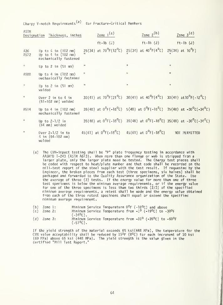
3.2.3. Toughness requirements
To assure satisfactory fracture resistance, codes generally specify minimum levels of
Charpy V-notch (CVH) impact toughness for low- and intermediate-strength steels. Nonferrous
materials such as aluminum and copper alloys do not exhibit a ducti le-to-brittle transition,
and, thus, are not usually toughness tested. Toughness requirements for most types of
structures are based on prior experience, however, an increasing number of fracture crite-
ria are being derived on the basis of fracture mechanics considerations as is the case for
bridges, gas pipelines, and nuclear pressure vessels. The various requirements are summa-
rized below.
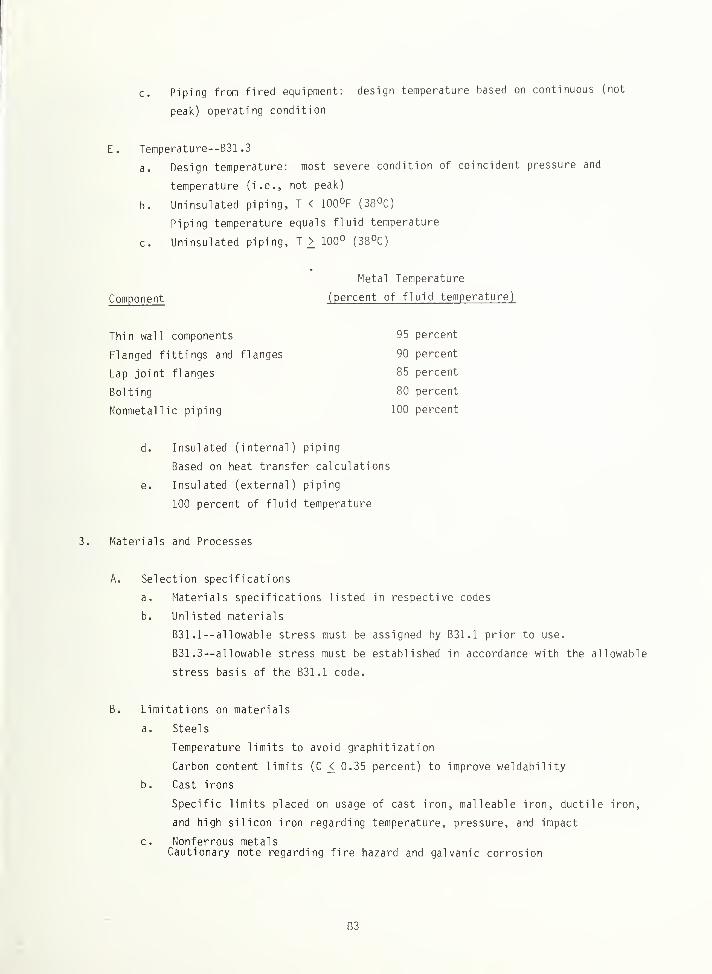
The toughness requirements for pressure vessels (ASME Section VIII) and piping (ANSI
B31.1 and B31.3) are a function of strength level, deoxidation practice, and heat treatment.
Minimum CVfl values for carbon and low alloys steels are specified in terms of average ab-
sorbed energy at a specified temperature. 17. 7J (13 ft lb) for strengths of 448 MPa (65 ksi)
and lower, 20.4J (15 ft lb) for strengths ranging from 448-517 MPa (65 to 75 ksi), and 27 .2J
(20 ft lb) for strengths ranging from 517-655 MPz (75 to 95 ksi). The toughness requirements
for higher strength steels, steels heat treated to enhance strength, and stainless steels are
specified in terms of notch ductility as measured in a CVN test, .38 mm (.015 inch) lateral
expansion is required. The test temperature for all grades is the design temperature or the
minimum temperature at which pressure will be applied, whichever is lower. A lower test
temperature must be used when subsize tests are conducted and the subsize width is less than
80 percent of the material thickness.
The toughness requirements on ship steel plates depend on the grade, plate orientation,
and strength level. The steels used in low stress and moderate temperature locations.
Grades A, B, and AH, do not have any fracture toughness requi rements . Steels used for crack
arrestor strakes, for low temperature applications, or for locations otherwise deemed crit-
ical must meet toughness requirements specified in the ABS rules. The CVN toughness require-
ments range from 19-34J (14 to 25 ft lb) depending on strength level and orientation. Tost
temperature and frequency of testing depend on the grade. For example, grades D and DH are
tested at -200C, 3 specimens from each 36.4 Mg (40 tons); and grades E and EH are tested at
-40 C, 3 specimens from each plate. For many applications, it is permissible to use grades
DS or CS, which do not require testing, in place of grades D or E, respectively.
13
Experience has shown that grades DS and CS consistently meet the toughness requirements
for grades D and E, respectively, due to the controls on chemistry, deoxidation practice,
and heat treatment. The idea of using metallurgical controls to assure toughness in place of
CVn requirements is unique to the ABS rules. This precedent has potential value for other
codes because the metallurgical controls contribute directly to toughness whereas the Charpy
requirements simply measure toughness.
The CVn toughness requirements discussed above are conducted either at the minimum
service temperature (e.g., the ASME approach) or at an arbitrarily low temperature (e.g.,
ABS grade E) under impact loading conditions. An alternative approach is to use actual
loading rates and factor in the various design features pertinent to the particular design.
This approach is used in the AASHTO bridge code. Here, the test temperature is increased by
an amount equal to the shift in transition temperature as the loading rate is decreased from
the impact rate used in CVM tests to the maximum loading rate expected in bridges. The
resulting CVN impact toughness requirements are 34J (25 ft lb) at EPC (7QOF) above
the minimum service temperature for low- and intermediate-strength steels.
3.3. Design and Analysis
Design is the arrangement and proportioning of structural members to withstand specified
loads whereas analysis is the determi nati on of the stress distribution in given structural
members. Both procedures are based on analytical methods of stress analysis, ranging from
strength of materials techniques to finite-element analysis using large computers. Obviously
the functions are closely related.
3.3.1. Design for fracture control
Good design practices are essential to fracture control. The most common methods of
fracture control used in design are to lower the design stress, to improve the design of
details, and to provide redundant load paths. Another design practice that is very helpful,
but less formalized in the codes, is to provide the accessibility needed to facilitate
fabrication, erection, and inspection.
The use of lower design stresses has evolved as a means of reducing the incidence of
fracture in many codes. The approach was used in the boiler and pressure vessel industry
where numerous failures occurred in the early 1900's. Through the years, the allowable
stress was lowered (as a percentage of minimum tensile strength) thereby greatly decreasing
the number of failures in succeeding years. The approach is basic to most codes. For exam-
ple, the ASME code for pressure vessels limits the allowable stresses in welds in accordance
with joint location, joint design, and degree of inspection. The API code for offshore
structures requires lower stresses for waterline braces because of corrosion fatigue
considerations. The ANSI gas pipeline code requires lower stress as a function of geographic
location, i.e., lower stresses where the consequences of failure are greater.
14
The elimination or reduction of stress concentrations and structural discontinuities
is an effective means of fracture control. Cracks usually start at specific design details
(e.g., connections, cutouts, stiffeners, etc.). Considerable improvement in fatigue behavior
can be obtained in smoothing the flow of stress at details. The most notable examples to
illustrate the significance of poor design details are the Liberty Ships of World War II.
The majority of fractures in these ships started at the corners of square hatch cutouts at
the top of the shear strake--desi gn practices that were subsequently eliminated in the ABS
rules
.
Design detail has the greatest importance in fatigue critical structures. For example,
the allowable fatigue stress range in the AASHTO bridge code varies from 110 flPa (16 ksi)
for butt wolds ground flush to 17.2 MP'a (2.5 ksi) for an as-welded cover plate whore there
is an abrupt change in section. Similarly, the AWS fatigue curves for offshore structures
vary by more than a factor of 10 on stress, depending on the particular structural detail.
The use of multiple load paths to provide structural redundancy is an effective moans
of preventing fracture in structures such as bridges, offshore structures, and ships. This
practice is encouraged in the AASHTO bridge code by designating as fracture critical those
tension components that are not redundant and whose failure might result in the collapse of
the bridge. Ships are not normally fail-safe, but the IMCO code for LNG carries (adopted
by ABS and USCG) requires double side shells, a double bottom, and transverse hull heads to
separate the cargo spaces--provi si ons that provide multiple load paths.
3.3.2. Standard details
Standard design details and associated analysis procedures are specified in most codes
to assure continued use of practices known to give satisfactory performance in other struc-
tures. notable examples are weld joint designs, welded connections, and rei nforcoment of
openings. Standardized design practices are particularly well developed for design codes
for pressurized containers such as the ASME pressure vessel code, the AtJSI piping codes, and
the API storage tank code.
3.3.3. Analyses
Design codes for most classes of structures require the analytical determination of the
stresses and deflections caused by the imposed loads and the determination of their signifi-
cance with respect to strength, stiffness, and stability criteria. To perform satisfactorily
the structure must withstand the service loads without yielding, deflecting excessively or
buckling. After designing to these criteria, the code may require that the fracture and
fatigue characteristics of the structure be evaluated. Because many failures of structures
or structural members occur by fatigue or fracture, it is desirable to consider these failure
modes during initial design when it is easier to make changes, e.g., in the geometry of cer-
tain details.
15
Codes that require fatigue analysis include the ASME Pressure Vessel Code Section VIII,
Division 2, the AWS Structural Welding Code (offshore structures), the AASHTO Bridge Code,
and to a lesser extent, the ANSI B31.1 and B31.3 piping codes. Two types of structures may
require a fracture mechanics analysis: 1) LNG shipboard containment systems designed to
pressure vessel requirements and not requiring a secondary barrier, and 2) nuclear pressure
vessels when in-service inspection reveals flaws that exceed original acceptance requirements.
3.3.4. Fatigue control
Fatigue control in the code approach generally is based on the prevention of crack
growth by using S-N curves to prevent initiation of a crack. The analysis is based on
extensive testing, a conservative estimate of the loads, a fairly accurate stress analysis,
and large factors of safety to account for material and fabrication variability. Design of
details can affect the allowable stress range significantly, as was noted in section 3.3.1.
S-N curves usually are obtained in one of two ways:
a) Results of smooth polished test specimens are used to obtain the basic fatigue
properties of the material. The stress range is divided by a fatigue stress concentration
factor to estimate the fatigue lives for a particular local geometry (e.g., as received sur-
face, notches, weldments, etc.). This "derived" S-N curve is then used to estimate the life
of a structure at a particular stress range, with appropriate factors of safety on life.
b) Results of actual fabricated members are used to obtain the fatigue properties
of the material in the actual service condition. Obviously there is no need to use any
stress-concentration factors to further reduce these results because the geometrical factors
(e.g., stress concentrations) are an integral part of the test specimens. The AASHTO bridge
specifications follow this approach by categorizing details from A to E. Category A refers
to smooth plates, category B to butt welds with reinforcement ground smooth, and categories
C, D, and E refer to weldments with increasing severity of stress concentration. For each
category from A to E, the code allowable fatigue stress level for 2,000,000 load cycles is
reduced from 110 MPa (16 ksi) to 17.2 MPa (2.5 ksi).
Conventional procedures for estimating structural fatigue-life expectancy are based on
the establishment (through appropriate material or structural tests) of a life estimate as
described above. After obtaining these results, a somewhat arbitrarily chosen factor
(usually ranging from 2 to 5) is applied to reduce this estimate to a presumably safe
service life. The size of this factor usually is based on judgment or probability analysis
to account for the variability or scatter associated with fatigue testing.
16
3.4. Quality Assurance
Quality assurance is the system of controls used to ensure that the as-fabricated
structure conforms to the code requirements. For many structures built to code requirements,
the Q/A system can be complicated by the use of different organizations to design, fabricate,
erect, inspect, and use the structure. Many of the codes clearly define these responsi-
bilities, as discussed below.
3.4.1. Material procurement controls
As discussed in section 3.2.1., a variety of material procurement specifications is
used in the various codes. The most common types are the ASTM specifications. The ASTM
specifications have requirements on manufacture, heat treatment, chemistry, mechanical
properties, dimensional variations, test specimens and methods, quality, repair by welding,
marking, inspection, and test reports.
For many products, including structural and pressure vessel steels, the purchaser has
rights of inspection. For example, ASTM A6 (structural steels) and ASTM A20 (pressure vessel
plates) specify: "The inspector representing the purchaser shall have entry, at all times
while work on the contract of the purchaser is being performed, to all parts of the
manufacturer's works that concern the manufacture of the material ordered. The manufacturer
shall afford the inspector all reasonable facilities to satisfy him that the material is
being furnished in accordance with the specification."
The manufacturer reports all test results, including the chemical analysis of the heat,
to the purchaser when required and requested. Conformance to the applicable specification
requirements is certified on the mill test reports. Subsequently, the purchaser may perform
a product analysis on all or any part of the order and has the right to reject the material
if it fails to meet the chemistry requirements of the procurement specification.
3.4.2. Fabrication and processing controls
The fabrication and processing controls comprise a major part of most codes. Good
workmanship is essential to fracture control in code structures because of the uncertainties
of inspection during fabrication and erection and because of the limited inspection most
structures receive during service. Each of the codes establishes requirements and/or
recommended practices for the major fabrication and processing operations applicable to that
class of structures, e.g., welding, forming, and heat treatment.
Detailed consideration is generally given to welding and associated activities. The
general approach used in most codes to assure weld integrity is to specify requirements for
workmanship, for qualification of materials, procedures and welders, for weld quality,
inspection and repair welding, and for post-weld heat treatment.
17
In addition to the design and fabrication codes, there are codes that relate specifically
to welding e.g., API Standard 1104--Standard for Welding Pipelines and Related Facilities,
Section IX of the ASME Boiler and Pressure Vessel Code--Wel di ng and Brazing Qualifications,
and the AIJS Structural Welding Code--Steel. The qualification requirements of ASME Section
IX are used for many types of pressure-containing weldments, e.g., by the other sections of
the ASME code, by the AIISI B31.1 and B31.3 pressure piping codes, and by the API 620 Storage
Tank Code.
3.4.3. Inspection
Many of the codes distinguish between examination, a quality control tool, and inspection,
a proof of compliance to code and contract requirements. Examinations are the quality con-
trol functions performed by personnel employed by the material supplier, fabricator, or
erector. Inspections are the proof-of-compl i ance functions performed for the owner by the
authorized inspector. Codes generally specify the qualifications of the authorized inspector.
The inspector is permitted free access to all parts of the site whore manufacture of the
material or fabrication and erection of the structure takes place. The duty of the inspector
is to conduct all tests and inspections necessary to be satisfied that all code and contract
requirements are met.
Inspections common to most codes include verifications that 1) materials conform to the
applicable specifications, 2) welding procedures and welders are qualified, 3) heat treat-
ments are properly performed, 4) nonconforming materials and welds are properly repaired and
re-examined, 5) required NDE and tests are performed and the results are acceptable, and
6) dimensional tolerances and arrangement conform to the engineering drawings.
3.4.4. Verification testing
Proof testing is used as a quality control tool for many classes of structures,
particularly pressure vessels and piping. For pressure containment structures, hydrotesting
or pneumatic testing generally involves loading the completed assembly to a pressure level
above that anticipated in service. The proof-stress factors (proof-pressure/design pressure)
range from 1.1 to 1.4, depending on the type of structure, the intended service, and the
testing medium. Oil pipelines, LNG storage tanks, and pressure vessels are hydrotested to
1.25 times the design pressure. If a pressure vessel cannot be filled with water, it is
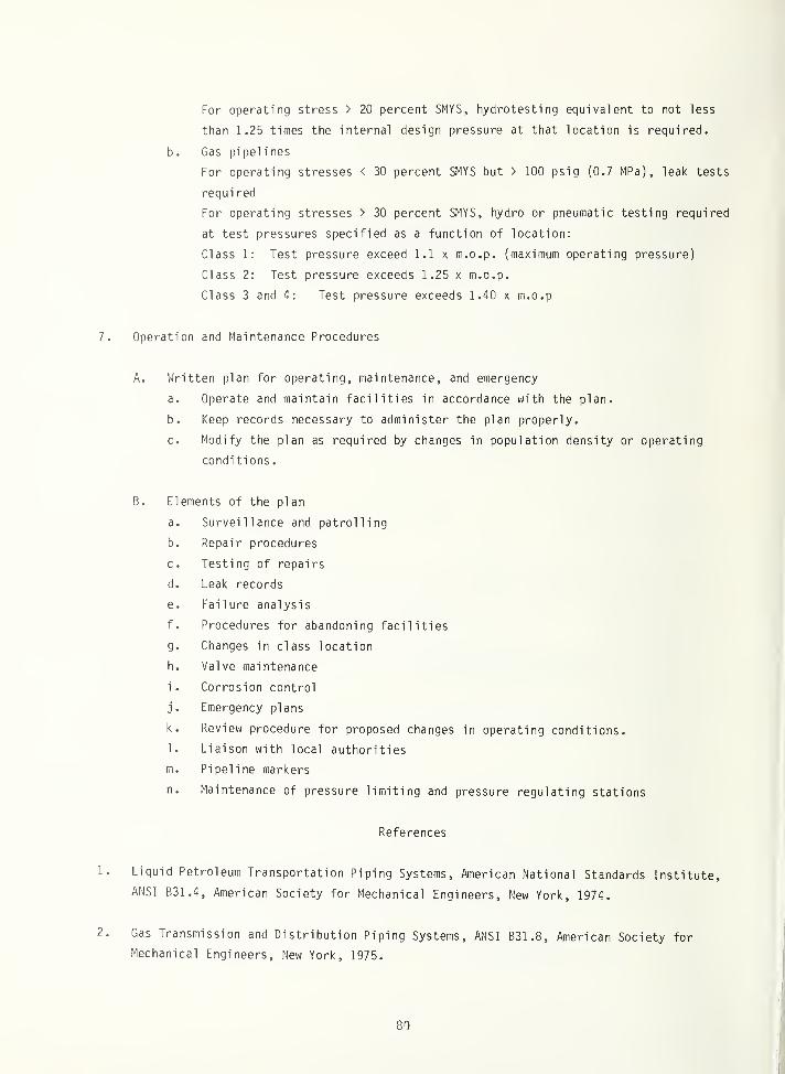
pneumatically tested to 1.15 times the design pressure. The proof-stress factors for gas
pipelines vary form 1.1 to 1.4 depending on location. Piping subject to low internal pres-
sures is simply leak tested, e.g., gas pipelines with stresses below 30 percent of yield
strength or oil pipelines with stresses below 20 percent of yield strength.
18
3.5. In-Service Controls
Many of the codes are limited to the design and fabrication requirements and do not
cover in-service controls. Notable examples are the ASME Section VIII Pressure Vessel Code,
ANSI B31.1 and B31.3 Pressure Piping Codes, and the API 620 Storage Tank Code. Extensive
coverage is given to in-service controls in the following cases: The ABS Rules for
Shipbuilding, the ANSI B31.4 and B31.8 codes for oil and gas pipelines, the API RP 2A
Recommended Practice for Offshore Platforms and the ASME Section XI Rules for Nuclear Power
Plant Components. In those cases where the codes do not cover in-service controls, the owner
and in some cases, local authorities, may require periodic surveys and maintenance. When
repairs are necessary, the materials and procedures may have to conform to the requirements
specified in the code for initial construction.
In pressure containment structures, time histories of pressure and temperatures, when
applicable, are generally recorded to monitor service usage. For complex structures such as
bridges, ships, and offshore platforms, periodic surveys are preferred as discussed in
section 3.5.2. Pressure monitoring for oil pipelines is required to assure that at any point
in the piping system 1) the maximum steady-state operating pressure and static head pressure
do not exceed the specified pressure ratings, and 2) the pressure rises due to surges do not
exceed the internal design pressure by more than 10 percent. Similar requirements are
generally involved in all pressure containment structures.
3.5.1. Periodic inspection
Periodic inspections are required for most classes of structures and are known as patrol
programs, surveys, and in-service inspections. For pipelines, the operating company main-
tains periodic patrol program to observe surface conditions on and adjacent to the pipeline
right-of-way, indication of leaks, construction activity other than that performed by the
operator, and any other factors affecting the safety and operation of the pipeline. Patrols
are required at relatively short intervals, e.g., two weeks for oil lines and one week for
LPG lines in developed areas. Annual surveys are required for specified locations in off-
shore platforms (splash zone and critical above-water members), and ships (steering systems,
specified valves, coamings, hatch covers, and locations particularly liable to rapid
deterioration). Additional surveys are required for the remainder of the ship or offshore
structure; special periodic surveys are scheduled for ships at four-year intervals and for
offshore structures at five-year intervals or following exposure to severe loading conditions.
In-service inspections of nuclear power plant components are scheduled at intervals ranging
from 3 to 40 years, depending on the particular inspection program, the component class, and
the operating experience. The scheduling generally coincides with plant outages due to
refueling or maintenance.
19
3.5.2. Maintenance and repair
The oil and gas pipeline codes (ANSI B31.4 and B31.8) are the only codes that explicitly
treat maintenance. The pipeline operator is required to have detailed plans and instructions
for maintenance of the system, including corrosion control, right-of-way maintenance, and
procedures for maintenance and repair of the pipeline, including valves, pump stations,
terminals, and tank farms.
4. THE PERFORMANCE SPECIFICATION APPROACH TO FRACTURE CONTROL
The performance specification approach to fracture and fatigue control is used for
high-technology weight-critical structures where structural safety and reliability are
essential. The main feature of this approach is the requirement that crack-like flaws of
specified size must be assumed to exist in worst-case locations throughout the as-fabricated
structure. Parts deemed susceptible to crack growth and fracture are identified as
fracture-critical and are subject to the requirements of a comprehensive fracture control
plan. The approach has been applied by the Air Force to aircraft, by NASA to spacecraft and
missiles, and by the Navy to hydrofoils.
The performance specification approach is based on 1) a detailed knowledge of the
anticipated operating conditions, particularly the service load history; 2) a thorough
evaluation of the selected materials and of representati ve joints and components; 3) a
complete structural analysis of the design, including stress, fatigue, and fracture analyses,
4) a comprehensive quality control program to assure that the as-fabricated structure has the
properties and quality levels assumed in design; and 5) an effective in-service program of
usage monitoring, maintenance, inspection, and repair. The following discussion emphasizes
the approaches to each of the elements of fracture control taken by the Air Force in the
Aircraft Structural Integrity Program, which is the outstanding example of the performance
specification approach.
4.1. Structural Design Conditions
Structural design conditions are generally stipulated in the procurement contract. The
conditions may be explicitly stated, as is generally the case for service life, e.g., "the
design life shall exceed 20 years." More commonly, the conditions are stipulated indirectly
through performance requirements (e.g., a 7g aircraft at specified velocity and altitude),
planned operational usage (e.g., 4000 flights of specified mission profiles), and refer-
enced specifications. Early in the design stage, the contractor must develop explicit
criteria consistent with the contract and specification requirements which are subject to
approval by the contracting agency.
20
Success of the performance specification approach is dependent upon a valid and complete
set of structural design conditions. The basis for the structural design criteria for USAF
aircraft is briefly summarized below and given in more detail in the Appendix. Maximum design
loads are based on the specified performance requirements. The fatigue loads spectrum is
based on planned operational usage and the load exceedance data of MIL-A-8866B. The chemi-
cal and thermal environment is characteri zed in terms of intensity, duration, and
f requency-of-occurrence of all exposures based on planned operational usage. Initial damage
assumptions are based on the requirements of MIL-A-83444. Safety factors on static strength,
fatigue life, and safe crack-growth intervals are based on the applicable military
specifications.
4.2. Materials
In the performance specification approach, materials and processes are selected by the
contractor on the basis of prior experience, trade-off studies to optimize weight and cost,
and requirements for system safety and reliability. There is not a set list of materials
that limits material choice as in the code approach, but the need for extensive character-
ization of the mechanical properties tends to result in the choice of materials previously
used. However, the selected materials and processes are subject to approval by the procuring
agency
.
The properties of the selected materials must be thoroughly characterized in the
appropriate product forms and thickness ranges. The influence of processing on the material
properties in the as-fabricated structure must be assessed. Several sources of data are
available for most materials, including handbooks and data from previous programs available
to the contractor and to the procuring agency. Gaps in the data base are filled by tests
conducted by the contractor.
Material procurement and processing specifications are prepared for each material,
product form, and material /process combination selected for usage in fracture-critical parts.
These specifications should invoke controls that are sufficient to preclude the use of mater-
ials in the structure that have properties inferior to those assumed in design. The speci-
fications are prepared by the contractor and approved by the procuring agency.
4.3. Design and Analysis
The role of the design and analysis functions is to integrate materials and structures
technology into the design of safe, functional, and economical structures. The design should
incorporate the results of the structural analyses of strength, rigidity, fatigue life, and
fracture resistance. Careful attention to design detail is essential because fatigue cracks
initiating at stress concentrations are perhaps the most likely source of failures.
21
The two principal design options for providing damage tolerance are the fail-safe and
the safe-life approaches. In the fail-safe approach, fracture safety is provided by struc-
tural redundancy. Inspectabi 1 i ty is essential to fail-safe design to assure detection of the
initial failure before the damage spreads beyond control. In the safe-life approach, the
stress levels are limited such that a flaw should not grow to critical size during the life
of the structure. When sufficient i nspectabi 1 i ty exists, this latter approach can be modi-
fied to provide for a safe inspection interval--at which time the structure is inspected and
certified for another interval of safe operation.
Extra caution is required in the design and analysis of structural joints--both
mechanically fastened and welded. Joints are the areas of greatest uncertainty because of
stress concentrations, fabrication defects, residual stresses, and questionable load paths.
Design concepts should be evaluated and analysis procedures should be verified by conducting
static strength and fatigue tests on representative joints. Care should be taken in locating
joints to avoid high-load areas and compounding stress concentrations whenever possible.
A complete structural analysis of the design should be conducted on a timely basis to
permit iteration of the design/analysis sequence and optimization of the design. Stress
analysis is used to verify airframe strength, to provide stresses for fatigue and fracture
mechanics analyses, to identify fracture critical components, and to select components and
loading conditions for structural tests. Fatigue analysis is used to determine the stress
limits that must bo imposed throughout the structure to avoid fatigue failure during the
specified service life. Fracture mechanics analysis is used to determine the stress limits
necessary to assure that a preexisting flaw of assumed initial size will not grow to critical
size during the specified service life, or in the case of inspectable structures, during the
interval of service between inspections. Fail-safe analysis is used to verify that failure
of a single member will not cause complete structural failure and further to verify that the
fatigue life of the remaining structure is sufficient to permit detection and repair of the
failed member before total structural failure occurs.
4.4. Quality Assurance
The quality-assurance program is the system of controls that ensures that the as-
fabricated structure conforms to the design requirements. The program should assure quality
throughout the design, fabrication, installation, and service life of the structure. Each
organizational element contributes to quality assurance e.g., engineering assures the
correctness of drawings and specifications;, inspection verifies dimensional and quality
requirements, etc.
In the performance specification approach, the engineering drawing should be used to
transmit the fatigue and fracture control requirements relative to materials; processing,
fabrication, and inspection of specific parts. Fracture-critical parts should be so identi-
fied on the drawing. Notes on the drawing should be used to invoke the material procurement
22
material processing specifications, fabrication controls, and inspection and corrosion
protection requirements. Other elements of quality assurance such as traceabi 1 i ty ,proof
testing, and verification testing should be applicable to the total system--! nstead of to
individual parts.
4.5. In-Service Controls
An effective in-service program of usage monitoring, maintenance, inspection, and repair
is essential to the success of the performance specification approach to fatigue and fracture
control. The duration and severity of usage should be monitored to assure that service
operations do not exceed design limits. Safe-usage intervals should bo determined on the
basis of fatigue, fracture mechanics, creep, wear, and corrosion control considerations.
After completion of a usage interval, periodic inspection, maintenance, and repairs should be
performed to the extent necessary to assure satisfactory performance during the next usage
i nterval
.
5. FRACTURE CONTROL CONCEPTS FOR NAVAL SYSTEMS
The purpose of reviewing fracture control practices used in a wide range of industries
to identify promising concepts that could be developed for Naval use. In this section,
selected concepts are discussed. The relative importance of the various concepts and the
specific applicability are not addressed; the purpose is simply to identify those industry
practices that merit consideration by the Navy for further development.
5.1 Steel Toughness Requirements
The establishment of toughness requirements is a difficult task for all structures where
brittle fracture is a credible failure mode. Innovative approaches used in specific codes
that may have broad applicability are described below.
5.1.1. The strain rate shift
The rate of loading (slow, intermediate, or impact) can have a significant effect on the
fracture toughness of structural steels. This behavior is shown in figure 1 for a 345 MPa
(50 ksi) yield strength structural steel. Note that the toughness transition for
intermediate-loading rate occurs over 80OC below that for impact loading. The transition
temperature for slow-loading rate is even lower. If the service loading rates are intermediate
(as has been shown to be the case for bridges) or slow, satisfactory notch-toughness levels
can be obtained well below the dynamic transition behavior, i.e., below the NOT temperature.
For Navy structures subjected to slow or intermediate rates of loading, this approach
may be viable. However it should be emphasized that other factors such as service experience.
23
design and fabrication controls, and actual fatigue tests of welded beams were considered
before AASHTO established their material specification on the basis of the loading rate
shift.
5.1.2. Metallurgical controls
The ABS rules for ordinary strength steels include two grades that require toughness
testing, grades D and E. For most applications, it is permissible to use grades DS or CS,
which do not require testing, and consequently cost less, in place of grades D or E,
respectively. The reason for deleting test requirements is that experience has shown that
grades DS and CS consistently meet the toughness requirements for grades D and E, respec-
tively, due to controls on chemistry, deoxidation practice, and heat treatment. The idea of
using metallurgical controls to assure toughness in place of Charpy impact requirements has
potential applicability to Naval specifications. The metallurgical controls contribute di-
rectly to toughness whereas the test requirements simply measure toughness.
5.1.3. Toughness saturation
The toughness requirements for line pipe have been extensively studied by AISI, AGA, and
British Gas. The results indicate that the notch toughness (e.g., as measured by Charpy
V-notch or drop-weight tear tests) required to arrest a running crack is simply related to
the hoop stress level and the pipe dimensions. Increasing the toughness to higher levels
does not improve performance; i.e., the toughness is saturated. Similar relationships have
been developed to control crack initiation. That is, above a certain toughness level, as
shown in figure 2, critical crack size is flow-stress dependent and independent of toughness.
Figure 2 shows the relationship between flaw size and toughness for a given pipe geometry
and stress level using relationships developed by Battelle for the AGA. In this figure,
increasing the toughness above 70J (50 ft lb) has no further effect on critical flaw size.
Similar curves can be drawn for any grade or size of pipe operations at the specified stress
level. In summary, meaningful and quantitative toughness values can be specified above which
failure is independent of toughness. Since the values vary with pipe dimensions and stress
level, they are not included in the API pipe specifications, but are specified in procurement
specifications for specific pipelines.
5.2. Weld Quality Standards
Weld quality standards are generally established on the basis of workmanship
considerations, i.e., quality levels that a qualified welder can consistently meet when the
proper consummables and equipment are used and the welding conditions (weather, joint
accessibility, etc.) are satisfactory. Workmanship standards can be more restrictive than
necessary to achieve structural integrity in the weld. Two approaches to weld quality based
:4
on fitness-for-service considerations have recently been developed: One for as-welded
structures and the other for cases where defects have been found during periodic in-service
inspection.
5.2.1. Fitness-for-service
In 1976, alternative weld quality standards were developed for the girthwelds of the
trans-Alaska oil pipeline on the basis of a fitness-for-service evaluation. In this eval-
uation, allowable flaw size curves were calculated using fracture mechanics models that
relate flaw size to applied stress and material toughness. Parameters for the analysis were
the worst-case operating stresses and .the lower bound material properties. In addition,
safety factors were applied to the calculated flaw sizes to conservatively account for
uncertainties in the analytical models and the inspection methods. The end results of the
evaluation were curves of allowable flaw length plotted as a function of the flaw depth
estimated from radiographic inspection records. Flaw sizes above the curve required repair,
and those below the curve were acceptable.
The alternative standards permitted acceptance of weld defects that were considerably
longer than those permitted in the API 1104 code. As a result of this work, the code writing
body and the regulatory authorities (Office of Pipeline Safety Regulation) have been considering
revisions to the code (API 1104) and the regulations (49CFRI92 and 49CFRI95) to permit use of
the fitness-for-service approach in the future.
5.2.2. Assessment of flaws detected during in-service inspection
Section XI of the ASME Boiler and Pressure Vessel Code provides procedures for deter-
mining the acceptability of flaws detected during in-service inspection that exceed the size
limits applicable to the as-fabricated vessel. The procedures, summarized in Appendix A of
Section XI, "Analysis of Flaw Indications," are based on the principles of linear elastic
fracture mechanics. They are applicable to ferritic steels in thick sections (^ 102 mm,
4 inch) with specified minimum yield strengths less than 50 ksi (345 MPa) and to structural
configurations that have simple geometries and stress distributions. Procedures are given
to size the flaw, represent the flaw as an elliptical (or semi-el 1 iptical ) crack, calculate
the stress intensity, estimate material toughness including irradiation effects, account for
fatigue crack growth and conduct the analyses for the various operating conditions. The
results of the analyses are minimum critical flaw sizes for normal and upset conditions. The
calculated flaw sizes and flaw evaluation criteria are used to determine if continued oper-
ation without repair of the observed flaw indication is acceptable.
25
5.3. Aerospace Practices for High Performance Structures
Several practices commonly used in the design and evaluation of airplanes and spacecraft
may be useful for high performance Naval structures.
5.3.1. Loads
The USAF has a continuing effort to characterize the loads encountered by aircraft during
service. The detailed consideration given to loads is essential to the design of aircraft
because stress levels throughout the airframe are limited by fatigue; i.e., higher stresses
could lead to fatigue failure. In contrast, Naval ships are designed to withstand massive
overloads due to combat operations or extreme sea states. Consequently, the routine cyclic
loads are of lesser importance. Exceptions occur in advanced systems that are subjected to
severe cyclic loading during normal operations, e.g., struts and foils in hydrofoil systems
and the 1 oad-transfer components in controllable-pitch propellers. For these exceptional
cases, detailed knowledge of the operational loads is essential to rational design.
Maneuver loads are statistical ly character! zed in terms of exceedance curves for each
mission segment, i.e., ascent, cruise, air-to-air combat, etc. Each exceedance curve indi-
cates the number of times a given level of acceleration is exceeded. Ai rframe loads can
then be computed for the velocity, altitude, gross weight, and configuration of the airplane,
during that mission segment. The number and magnitude of loads for each mission segment are
computed on the basis of the planned operational usage of the aircraft. The grand total of
all the loads is the maneuver loads spectrum for the aircraft.
The gust loads spectrum is derived from the continuous turbulence model specified in
MIL-A-8861. The atmospheric turbulence environment is simulated as a continuous random
process. A power spectrum of the turbulence represents the forcing function in the frequency
domain and a dynamic analysis is used to determine the load response of the flexible airframe.
The response characteristics are a function of the velocity and configuration of the aircraft.
The severity of the turbulence is primarily a function of altitude. The sum of all the loads
duo to the airframe response to the power spectrum for each mission segment is the gust loads
spectrum of the aircraft.
Additional loads analyses are conducted to account for cabin pressurization, taxi and
ground handling loads, operation of control surfaces, and combined gust and maneuver loads
during low-level contour operations.
5.3.2. Full-scale testing
Full-scale testing is an essential part of the USAF Airframe Structural Integrity
Program. Similar tests are not normally required for ships because of obvious practical
26
limits. Normally, ships are simply too big, too expensive, and too few to justify testing a
complete unit to destruction, flowever, there are some ships and, more commonly, subsystems
that may benefit from full-scale testing. Notable examples are, again (as in
subsection 5.3.1.), the struts and foils of hydrofoil ships and the controllable pitch prop-
eller system. The full-scale tests generally conducted by the USAF on a new aircraft are
described below.
Static tests are tests conducted on an instrumented airframe that simulates the loads
resulting from critical flight and ground handling conditions. The tests are used to verify
the stress analysis results by correlating strain survey results with analytical predictions
and to verify that the design ul timate -strength of the airframe exceeds specification
requi rements
.
Fatigue tests are tests conducted to evaluate the capability of the airframe to withstand
repeated applications of the fatigue loads spectrum. Cycling is continued for a minimum of
two service lifetimes or until the economic life is exceeded, i.e., until repairs are so
frequent or so major that the airframe is not worth fixing. The results are used to verify
that the economic life exceeds the design service life, to identify fatigue critical compon-
ents, and to provide a basis for establishing special inspection and maintenance requirements.
Damage-tol erance tests are a relatively new requirement for USAF aircraft. A series of
tests are conducted on full-scale articles with specified levels of induced damage, usually
fatigue cracks in critical locations. The size of the induced damage and the applied loads
approximate the initial damage conditions and residual strength requirements used in design.
The results verify the damage tolerance of the fracture critical parts and the ability of
the analysis to predict structural performance.
Additional tests are conducted in operating aircraft that verify airframe safety without
requiring destruction of the airframe. These include loads surveys, dynamic response tests,
sonic response tests, flight vibration and flutter tests, and rigidity tests. The test
philosophy and certain of the techniques may be applicable to Naval ships during sea trials.
5.3.3. Fracture critical parts
In the performance specification approach, only parts designated as fracture-critical
must conform to the requirements of the fracture control plan that exceed normal design
requirements. For the space shuttle program, NASA requires that fracture-critical parts be
identified on the basis of criticalness to structural fl i ghtworthi ness and susceptibility to
cracking or fracture. For USAF aircraft, fracture-cri ti cal parts are defined as those mem-
bers whose failure could result in loss of the aircraft and whose stress levels are limited
by the fracture mechanics analysis requirements. In summary, fracture-critical parts are
identified on the basis of the consequence and likelihood of fracture.
27
Identification of fracture-critical parts is a useful exercise to limit over-application
of fracture control requirements and to focus attention on those parts most likely to cause
fracture problems. Dravjing on the two Maval examples cited previously the performance
specification approach may bo limited to the controllable-pitch propeller instead of the
entire frigate, or to the struts and foils instead of the complete hydrofoil.
6. SUMMARY COMMEIITS
The prevention of fracture has always been a primary consideration in engineering design.
The many practices used in a variety of industries to prevent fracture have been reviewed.
Two general approaches are used; The code approach and the performance specification approach.
The code approach is used for nearly all commercial construction and is based on minimum
requirements on design, materials, fabrication, and quality assurance that are applicable
to a wide variety of configurations within a general class of structures, e.g., bridges,
pressure vessels, and merchant ships. The performance specification approach is used for
high performance structures where the inefficiencies associated with general codified rules
cannot be tolerated, e.g. aircraft and space vehicles.
Certain practices associated with the two approaches may be of potential value to the
Navy. The codes, which are continuously updated to incorporate potential improvements in
industry practice, contain many f racture-control concepts that may be less costly than the
practices used for Naval systems. The performance specifications used by the Air Force and
NASA include fracture-control practices that may be useful for high performance Naval sys-
tems .
Fracture-control practices used by industry that offer potential cost reductions for
Naval systems are related to the establishment of steel toughness requirements and weld
quality standards. Alternative concepts for establishing steel toughness requirements in-
clude the strain-rate shift approach developed for bridges, the metal 1 urgi ca 1 -control
s
approach used for merchant ships, and the toughness-saturation approach developed for line
pipe. Weld quality standards based on f itness-for-servi ce considerations have been used in
place of more stringent workmanship standards for inspection of pipelines and offshore struc-
ture and for in-service inspection of nuclear pressure vessels.
Fracture-control practices used for aerospace structures may improve the reliability of
certain Naval systems, particularly those advanced systems where the experience base is
limited. Practices worthy of consideration include loads characterization, full scale
testing, and formalized designation of fracture-criti cal parts.
28
7. ABBREVIATIONS
AASHTO
ABS
AGA
AIAA
AISC
AISI
ANSI
API
ASIP
ASME
ASM
ASTM
AWS
CFR
CSA
ECP
ENSIP
FAA
IMCO
ISO
American Association of State Highway and Transportation
Official
s
American Bureau of Shipping
American Gas Association
American Institute of Aeronautics and Astronautics
American Institute for Steel Construction
American Iron and Steel Institute
American National Standards Institute
American Petroleum Institute
Aircraft Structural Integrity Program
American Society of Mechanical Engineers
American Society for Metals
American Society for Testing and Materials
American Welding Society
Code of Federal Regulations
Canadian Standards Association
Engineering Change Proposal
Engine Structural Integrity Program
Federal Aviation Administration
International Maritime Consultive Organization
International Standards Organization
29
NASA National Aeronautics and Space Administration
MBS National Bureau of Standards
NRC Nuclear Regulatory Commission
OCS Outer Continental Shelf
OPSR Office of Pipeline Safety Regulation
USAF United States Air Force
USCG United States Coast Guard
USGS United States Geological Survey
The authors gratefully
Acknowledgment
acknowledge the contributions of Peter W. Marshall of the Shell Oil
Company, Houston, Texas, who contributed the appendix section of Fracture Control for FixedOffshore Structures; and James A Begley of the Westinghouse Electric Corporation, Pittsburgh,Pennsylvania, who contributed the appendix section on Large Rotating Equipment for ElectricPower Generation.
30
APPENDIX
SUMMARIES OF FRACTURE CONTROL PRACTICES
USED FOR METAL STRUCTURES
CONTENTS: Page
Ships and Sea Systems
Merchant Ships------------------------------ 32
LNG Ships - Containment Systems --------------------- 35
Rules for Non-Destructive Evaluation of Hull Wolds (American Bureau of Shipping,
45 Broad St., New York).
35
LNG SHIPS - CONTAINMENT SYSTEMS
1. Overview
A. Codes and regulations
a. International Maritime Consultive Organization (IMCO) Code [1]
b. U.S. Coast Guard (USCG) Regulations [2]
c. American Bureau of Shipping (ABS) Rules [3]
B. Designs built in the U.S.
a. Avondale Shipyards, Inc.
Conch containment system [4]*
Free-standing, prismatic tanks
5083 aluminum plates and extruded shapes
b. Newport News Shipbuilding
Techniqaz containment system [5]
Membrane, prismatic tanks
304L stainless steel sheet
c. General Dynamics
Kvaerner-Moss ,containment system [6,7]
Free-standing, prismatic tanks
5083-0 aluminum plates
2. Structural Design Conditions
A. Design life: 20 years
B. Loads: summarized in SSC-258 [8]
a. Static pressure: cargo weight
b. Vapor pressure: pressure relief value setting
c. Dynamic effects due to ship motions
roll, pitch and heave conditions defined [9]
d. Thermal streses: AT = 190°C
e. Flooding: applicable to free-standing tanks
f. Self weight: applicable to free-standing tanks (lifting required)
g. Fatigue loads [10]
C. Initial damage assumptions
a. Hull damage: IMCO Section 2.3 [1]
b. Prismatic design [4,5]
Secondary barrier required
Primary barrier assumed to be failed for hull temperature determination
^Commercial equipment is mentioned in this document to adequately identify certain LNGcontainment systems. In no case does this imply endoresement or recommendation by the NationalBureau of Standards.
36
c. Spherical design [1]
Leak-before-break required
Assume through-thickness crack of length 2 x thickness
Safe crack growth for 15 days under worst-cast storm conditions
D. Safety factors
See section 3C on allowable stresses and 4B on fatigue analysis.
3. Materials and Processes
A. Selection, specifications'
a. Steel alloys
9 percent Hi; ASTM A353 and ASTM A553
36 percent Ni (Invar): ASTM A658
Austenitic stainless steels: ASTM A240
b. A1 umi num al 1 oy
5083-0 sheet and plate: ASTM B209
5083-H 111 extrusions: ASTM B221
B. Properties
a. Room temperature guaranteed minimum properties used [4]
b. Exception is Conch design where allowables are based on strength at LNG
temperatures [4]
C. Allowable stresses
a. Membrane tanks [l]--not specified (membranes not structural).
Tests and analyses must show compatibility of hull and containment system.
b. Free-standi ng-prismatic tanks [1] (independent tanks--type A)
Maximum stress is lesser of o^^j/2.66 or Otj,/l.33
where o^^j = tensile ultimate strength at room temperature
= tensile yield strength at room temprature
Note; Wold metal values for o^^j and o^y are used when the weld is
weaker than the base metal.
Froo-standi ng--spherical tanks [1,12] (independent tanks--type B)
om 1 f
OL < 1.5 f
Ob _< 1 .5F
OL + Ob 1 1 .5F
0[^ + Ob <. 1 .5F
37
where
Opi= equivalent primary general membrane stress
op = equivalent primary local membrane stress
Ob = equivalent primary bending stress
f = the lesser of o^y/A or o^y/B
F = the lesser of o^y/C or Oty/D
Equivalent stresses 0(~, are calculated by the Von Mises yield criterion:
2 2o = 0 + 0 - OO + 0TC X y X y xy
where and Oy are normal stresses and is the shear stress. The safety
factors A, B, C, and D specified by the USCG [10] are as follows:
9Ni
Factor
Steel Austenitic steels 5083-Al
A 4* 4
B 2 1.6 1.5
C 3 3 3
D ;L.5 1.5 1.5
*3 specified in IMCO
**3.5 specified by IMCO
Allowable stresses may be further limited by fatigue analysis, crack propagation analysis,
and buckling criteria.
D. Minimum toughness
a. 9Ni steel
30 ft lb (41 J) longitudinal and 20 ft lb (27 J) transverse at -196C
b. Fe-36Ni and 5083 A1 : none required
c. Austenitic steels: not required by USCG, optional to IMCO
d. 9Ni welds
20 ft lb (27 J) at -196°C for the following notch locations:
(weld parallel to rolling direction, specimens perpendicular to weld, notch
perpendicular to surface)
Weld metal
Fusion line
Heat affected zone: 1, 3, and 5 mm from fusion line
38
4. Desi gn
A. Design for danage tolerance
Double-side shell and double bottom required for hull structure
Fail safe provisions
a. Secondary barrier required for prismatic tank designs
b. Leak-before-break and safe crack growth after leak required for spherical
tank design. Fatigue spectrum for safe crack growth calculations is equiv-
alent to 15 days of worst-case storm conditions.
B . Standard detai 1
s
Each containment system design must be approved by the U.S. Coast Guard if the
ship is to enter U.S. coastal waters.
C. Joining practices
a. Production weld procedures must be qualified for each base material, each
type of consumrnable and welding process, and each welding position. Tests
are as follows:
Cross-weld tensile test
Transverse bend tests
Charpy impact tests (if required for base material)
riacrosecti on, microsection, and hardness survey
b. Free-standing tank shells: full penetration butt welds and full penetration
nozzle welds required.
5. Analysis
A. Stress analysis
a. Limits set by stress allowables, buckling criteria, fatigue, and crack
propagati on
b. Finite-element and closed-form methods used
E. Fatigue analysis
a. Membrane; fatigue testing of models required
b. Free-standing prismatic, fatigue analysis not required
Insulation and secondary barrier system models subjected to fatigue testing.
c. Free-standing spherical: cumulation damage fatigue analysis required
39
n
.
2n.
1
cw
where
n-j = number of stress cycles at stress level i in the fatigue
spectrum
N-j = number of cycles to fail for stress level i based on materials
S-N curve
Nj = number of cycles to fail for stress level correspond! ng to cargo
loading and unloading
1 i.e., safety factor >_ 2 on fatigue life
C. Fracture mechanics
a. Membrane and free-standing prismatic; not required
b. Free-standing-spherical
^cr f daLife = J worst-case storm conditions
^LBB
where C and n are crack growth rate parameters
^LBB“ crack size for leak before break = 2 x thickness
^CR = critical crack size
6. Qual ity Assurance
A. Material procurement and controls
ASTM requirements and IMCO minimum toughness requirements
B. Fabrication and processing controls
a. Held procedure qual ificaions required (See 2-D)
40
b. Production weld tests: free-standing tanks only
Frequency: every 50 m of butt weld
Type: bend tests and Charpy impact test (if required for procedure test)
Notch location:
9Ni steel: alternately in weld metal and HAZ
(worst location identified in procedure tests).
Austenitic steels: in center of weld
C. Inspection (NDE) [11,13]
a. Butt welds: 100 percent radiography
b. Ultrasonics, dye penetrant, and magnetic particle inspection sometimes
requi red
D. Hydrotesting
a. Membrane tanks
Coferdams and spaces adjacent to cargo tanks must be tested.
b. Free-standing tanks
1) Hydrotest to approximate as nearly as possible the design stresses
2) Pressure ip dome must at least equal the maximum allowable relief value
setting.
3) For spherical tanks, at least one tank per ship must bo instrumented
with strain gages to verify stress levels [13].
4) For prismatic tanks, stresses in primary members must not exceed
90 percent of Strain gage verification required if stresses
greater than 75 percent of are anticipated [4].
E. Verification testing
a. Membrane [14]
Component tests on:
"Waffle" panels (primary barrier)
Insulation system
Test boxes: 5m3 specimens with full-size waffle panels
b. Free-standing prismatic [4]
Fatigue tests on insulation panels with secondary barrier
c. Free-standing spherical
Leak-before-break tests [11,15]
References
1. Code for the Construction and Equipment of Ships Carrying Liquified Gases in Bulk
(International Maritime Consultive Organization, London, 1975). See also. Proceedings
of the Maritime Safety Council 3̂ , No. 3 (1976).
41
2. Liquified Flammable Gases, Code of Federal Regulations, Title 46, Part 38 (1977). See
also: Liquified Natural Gas, Views and Practices, Policy and Safety (U.S. Coast Guard,
CG-478, Feb. 1976).
3. Vessels intended to carry liquified gases (sec. 24 of Rules for Building and Classing
Stool Vessels, American Bureau of Shipping, flew York, 1977).
4. Potts, W. K., and Cuthbert, W. L., LNG carriers using the conch containment system.
Paper presented at the SflAnE mooting, Vancouver, B. C., Canada, May 1975, Society of
Naval Architects and Marine Engineers, New York, 1975.
5. Throe stainless steel membrane LNG tankers first of type made in U.S. A., Nickel Topics
4. Fracture Control Plan, Draft developed by the Structual Steel Design and Welding
Technical Committees of the AASHTO Subcommittee on Bridges and Structures in consort
with the Bridge Division of the Federal Highway Administration, April 1978.
63
Charpy V-notch Requirements for Fracture-Critical Members(a)
ASTMDesignation Thickness, inches Zone 1 Zone 2^*^^ Zone 3^*^^
ft-lb (J) ft-lb (J) ft-lb (J)
A36A572
Up to 4 in (102 mm)
Up to 4 in (102 mm)mechanically fastened
25(34)II
at 70°F(12°C) 25(34)II
at 40°F(4°C) 25(34) at 10°F)II
'Up to 2 in (51 mm)
II II II
A588 Up to 4 in (102 mm)
mechanically fastened
II II "
11
Up to 2 in (51 mm)
welded
II II II
II
Over 2 in to 4 in
(51-102 mm) welded30(41) at 70°F(21°C) 30(41) at 40°F(4°C) 30(41) atlO°F(-12°C)
A514 Up to 4 in (102 mm)
mechanically fastened35(48) at 0°F(-18°C) 5(48) at 0°F(-18°C) 35(48) at -30°C(-34°C
11
Up to 2-1/2 in
(64 mm) welded35(48) at 0°F(-18°C) 35(48) at 0°F(-18°C) 35(48) at -30°C(-34°C
II
Over 2-1/2 in to
4 in (64-102 mm)wel ded
45(61) at 0°F(-18°C) 45(61
)
at 0°F(-18°C) NOT PERMITTED
(a) The CVN-impact testing shall be "P" plate frequency testing in accordance withAASHTO T-243 (ASTM A673). When more than one flange or web is stripped from a
larger plate, only the larger plate need be tested. The Charpy test pieces shall
be coded with respect to heat/plate number and that code shall be recorded on themill-test report of the steel supplier with the test result. If requested by theEngineer, the broken pieces from each test (three specimens, six halves) shall be
packaged and forwarded to the Quality Assurance organization of the State. Usethe average of three (3) tests. If the energy value for more than one of threetest specimens is below the minimum average requirements, or if the energy valuefor one of the three specimens is less than two thirds (2/3) of the specifiedminimum average requirements, a retest shall be made and the energy value obtainedfrom each of the three retest specimens shall equal or exceed the specifiedminimum average requirement.
(b) Zone 1: Minimum Service Temperature 0°F (-18°C) and above(c) Zone 2: Minimum Service Temperature from -1° (-19°C) to -30°F
(-34°C).(d) Zone 3: Minimum Service Temperature from -31° (-35°C) to -60°F
(-51°C).
If the yield strength of the material exceeds 65 ksi(448 MPa), the temperature for theCVN value acceptability shall be reduced by 15°F (8°C) for each increment of 10 ksi
(69 MPa) above 65 ksi (448 MPa). The yield strength is the value given in thecertified "Mill Test Report."
64
LARGE ROTATING EQUIPMENT
for
Electrical Power Generation
1. Overview
A. Codes and regulations
Design practices are proprietary to the equipment manufacturers. There are no
design codes or federal regulafions applicable.
B. Equipment
a. Steam turbine rotors and shafts
b. Generator rotors
c. Steam and land-based gas turbine
d. Discs and wheels
C. Scope
Due to the absence of design codes for large rotating equipment, this summary is
limited to general information of a non-proprietary nature.
2. Structural Design Conditions
A. Design life; 40 years
B. Loads
a. Centrifugal stresses due to rotation
b. Thermal stress
c. Bending of large shafts from dead weight
d. Shrink-fit stresses for discs
e. Stop-start fatigue cycle
f. Small amplitude vibration
C. Initial damage assumptions
a. Company specific
b. Generally based on operating experience, backed up by fracture mechanics
analysis
D. Safety factors
a. Company specific
b. Factor of 2 on yield strength is typical
65
3. Materials and Processes
A. Selection, specifications
a. Generator rotors--ASTM A 469
b. Turbine rotors and shafts--ASTM A 470
c. Turbine rotor disks and wheels ASTM A 471
d. Proprietary company specifications, more rigorous than the ASTM
specifications, may bo the procurement requirements.
B. Processes
a. Basic elctric furnace melting
b. Vacuum treated prior to or during pouring to remove objectionable gases,
particularly hydrogen
c. Forged using equipment with sufficient power to hot work the metal throughout
its section. The axial center of the forging is maintained common with the
axial center of the ingot.
d. Heat treatment--quench and tempered (A469 and A 471) or double normalized
(A47C)
0 . Stress rel i ef--requi red after rough machining
C. Properties
a. Minimum tensile and impact requirements in accordance with procurement
specification (ASTM or company)
b. Companies have ongoing material evaluations to qualify suppliers and to
assess material variability.
D . A1 lowable stresses
Company specific
4. Design Practices
A. Based on successful operating history
B. Quality materials
C. Specified operating stresses
D. Minimal stress concentrati ons
66
5. Analysis
A. Stress analysis
a. Closed form methods
b. Finite element analysis
c. Photo elastic stress analysis
B. Fatigue analysis
a. Mainly conventional S-fl approach
b. Low cycle fatigue used to analyze discs
c. Fracture mechanics anal'ysi s--back up analysis and for in-service inspection
6. Qual ity Assurance
A. Material procurement controls
a. ASTM and company material specifications
b. In-house material eval uati on--check test not receiving inspection
B. Inspection
a. Ultrasonics (bore is critical region)
b. Magnetic particle
c. Defect limits are company specific
d. X ray where applicable, but generally parts are too big for x ray
C. Verification testing
a. Overspeed rotation tests
b. 20 percent overspeed--i ncreases stresses 40 percent
67
PRESSURE VESSELS
1. Overview
A. Codes
a. American Society of Mechanical Engineers (ASME) Boiler and Pressure Vessel
Code, Section VIII, Pressure Vessels
Division 1-applicable to vessels designed for pressures not exceeding
3,000 psi (21 MPa)-Factor of Safety against burst = 4
Division 2-Alternative Rules-more precise design and inspection procedures
are required than for Division 1-Pressures greater than 3,000 psi (21 MPa)
are al lowed-Factor of Safety against burst = 3
2. Structural Design Criteria
A. Design life-not specified
B. Loads
a. Internal or external pressure
b. Impact, including rapidly fluctuating pressures
c. Weight of vessel and contents
d. Superimposed loads from other equipment
e. Wind loads, and earthquake loads where required
f. Reactions of supports
g. Effect of temperature gradients
C. Initial damage assumption-none
"All injurious flaws shall be removed"
D. Safety factors
3 or 4 on burst, depending on Division 1 or Division 2 rules
3. Materials and Processes
A. Only certain materials permitted as given by Code Material
Specifications, Section II
Part A-Ferrous Materials
Part B-Nonferrous Materials
Part C-Welding Rods, Electrodes, and Filler Metals
68
B. Properties
Minimum tensile values as specified in Code
C. Special toughness reuirements
a. Carbon and low-alloy steels
Minimum Charpy V-Notch Impact Test Requirements for these steels vary from 10
to 20 ft lb (14 to 27 J) (depending on deoxidation) at minimum service
temperature. (Section VI 1 1 ,Di vision 2, AM-210)
b. Quenched and tempered ferritic steels
Minimum lateral expansion of 0.015 in (3.8 mm) at minimum service
temperature. (Section V 1 1 1 ,Di vi sion 2, AM-310) For service temperatures
below -20°F (-29°C), drop-weight NOT tests shall be made with NOT
(no-break) to be at or below that temperature.
D. Allowable stresses
a. Section VIII, Division 2, Alternate Rules
Referred to as design stress intensity values, S^,. Design allowable values
are given in Section VIII, Division 2, Article M-6, "Material Design Data,"
for materials as a function of temperature. For example, SA-372 steel with a
specified minimum yield of 35 ksi (241 MPa) and tensile of 60 ksi (413 MPa)
has a design stress allowable ranging from 20(aj/3) ksi (138 MPa) at
100°F (38°C) to 17 ksi (117 MPa) at 650°F (349°C).
b. Section VIII, Division 1
Design allowable stress values given in UG-23--"Maximum Allowable Stress
Values." For example. Table UCS-23 gives maximum allowable stress for SA-36
steel as 12.7 ksi (88 MPa). Minimum yield strength is 36 ksi (248 MPa) and
minimum tensile strength is 58 ksi (400 MPa). The allowable stress is less
than oj/4 because SA-36 is a structural grade.
4. Design and Analysis
A. Design requirements specified in Code.
B. Thickness of vessel parts are established by formulas given in Code using the most
severe combination of loadings and allowable stress intensities (also given in
Code for each material) expected to occur.
C. Formulas are based on maximum shear stress theory of failure.
D. Standard details
Acceptable transition details presented in Code--Design Requirements
69
E. Fatigue evaluation
a. Specific rules are established for conditions when fatigue analyses are
mandatory (Conditions A and B, Section VIII, Division 2, Alternate Rules,
AD-160)
.
b. Fatigue analysis based on S-N curves that have factor of safety of 20 on life
or 2 on stress.
c. Stress ranges for fatigue analyses are based on startup and shutdown, number
of operating pressure cycles, thermal stresses, and mechanical loading, e.g.,
piping reactions.
F. Experimental stress analysis shall be conducted to substantiate analysis of
critical parts for which theoretical stress analysis is inadequate.
5. Quality Assurance
A. Material procurement
Section II, Material Specifications-same as ASTM material specifications
B. Fabrication and processing control
General fabrication requirements given in Section VIII, Article F-1, General
Fabrication Requirements and Section IX, Welding and Brazing Qualifications.
C. Inspection
Section V, Nondestructive Examination
Various methods (radiographic, ultrasonic, magnetic particle, liquid penetrant,
visual, eddy current, and leak testing) are specified to detect both surface and
internal discontinuities.
D. Hydrotest
a. After all required heat treatments have been performed, the completed vessel
shall be sujected to either a hydrostatic test (Article T-3) or a pneumatic
test (Article T-4)
.
b. Hydrostatic test pressure to be not less than 1.25 times the design pressure
times the lowest ratio of design stress at the test temperature of the vessel
to the design stress at design temperature.
c. Pneumatic test can be used only if vessel cannot be filled with water.
Required pneumatic test pressure shall be not less than 1.15 times the design
pressure times the lowest ratio of design stress at test temperature to
design stress at design temperature.
E. Safety valves set approximately 10 percent above the operating pressure.
70
6. Fracture Mechanics Analysis
Not used in Section VIII, Pressure Vessels. Fracture mechanics i_s_ used in
Section III, Nuclear Power Plant Components.
71
NUCLEAR PRESSURE VESSELS
1. Overview
A. Codes and Regulations
a. American Society of Mechanical Engineers (ASME) Boiler
and Pressure Vessel Code - Section III - Nuclear Power
Plant Components
b. Nuclear Regulatory Commission (NRC)
2. Structural Design Criteria
A. Design life - not specified (fatigue curves ~ 25 years)
B. Loads
a. internal and external pressure
b. impact loads, including rapidly fluctuating pressures
c. weight of the component and contents
d. superimposed loads such as other components, operating
equipment, etc.
e. wind loads, snow loads, earthquakes
f. reactions of supporting lugs, rings, etc.
g. temperature effects
C. Maximum shear stress theory
a = 1/2 (a - a )
max 1 3
Generally o <max
at operating temperatures
Example: carbon steel - a =24 ksi (165 MPa), a = 45 ksi (310 MPa)y s u I c
max = 15 @ 100°F (38°C)
14.2 @ 30QOF (1490c)
12.9 @ 50QOf (260°C)
11.5 @ 700Of (3710c)
D. Detailed stress report showing stress analysis is required for normal
NASA, Marshall Space Flight Center Report SE-020-002-2H , June 17, 1974.
C. Fracture critical parts
The requirements of the fracture control plan are applicable to parts identified
as fracture critical. The selection logic for fracture-critical parts is shown in
figure A-1.
Structural Design Conditions
A. Design life--100 missions
B. Loads
All static and dynamic loads and pressures acting on the structure are determined
and distributed throughout the structure by rational analysis. Loads encountered
in each of the operational phases (launch, space, reentry, atmosphere, flight,
etc.) must be accounted for.
C. Environment
The structure must meet all the required design characteristics after (or during,
as applicable) exposure to all credible environments. Thermal, chemical, and
natural (rain, hail, blowing sand, etc.).
100
D. Initial damage assumptions
a. Initial crack-like flaws are assumed to exist throughout the structure. The
initial flaw size assumed in analysis is a function of the inspection
method.
b. Standard NDE flaw sizes
Flaw sizes detectable with a 90 percent probability of detection and a
95 percent confidence level by inspectors certified to Level II of
MIL STD 410 working to applicable aerospace industry and military standards.
These flaw sizes are assumed in routine fracture mechanics analyses.
c. Special NDE flaw sizes
Flaw sizes detectable (cigain with 90/95 statistics) by most-qualified
inspectors using part-specific inspection procedures. These flaw sizes are
assumed in the fracture mechanics analysis of specified parts where special
NDE procedures are used.
d. NDE capabilities
Inspection method
Penetrant or magnetic
particle
Ultrasonics
Flaw type
Surface flaw
(Depth X length)
Embedded flaw
(di ameter)
Standard NDE
0.19 X 0.38 cm
(0.075 X 0.150 in.)
or equivalent area
0.254 cm (0.100 in.)
Special NDE
0.063 X 0.127 cm
(0.025 X 0.050 in.)
or equivalent area
0.12 cm (0.047 in.)
Radiographic Surface or embedded
(depth X length)
0.7 X 1.4t
Min length = 0.38 cm
(0.150 in.)
0.6 X 1.2t
Min length = 0.127 cm
(0.050 in.)
t = thickness
E. Safety factors
Recommended values (NASA SP-8057) for application to mechanically induced loads
and pressure (i.e., not thermally induced). Limit load is defined as the maximum
load expected to act on a structure in the expected operating environment. Limit
pressure is the maximum differential pressure expected to occur in service.
a. General unpressurized structure
1.5 on limit load results in o(stresses) < (ultimate tensile
strength). 1.0 on limit load results in a < (yield strength)
b. Pressurized structure
1.5 on limit load applied at limit pressure results in a < a^^j.
101
2 on limit pressure applied at zero load results in a <
1.0 on limit load results in a < o^-y.
c. Main propellant tanks
1.4 on limit pressure results in a <
1.1 on limit pressure results in a <
d. Pressure vessels
2.0 on limit pressure results in a < a^^j.
e. Fati gue--factor of four on mission cycles
3. Materials and Process
A. Selection
a. A list of approved materials is maintained by the integration contractor
(Rockwell International).
b. Selection of structural materials from this list is based on specified
materials selection criteria (Rockwell International Shuttle Specification
MF0004-003, September 20, 1974).
B. Properties
a. Sources: approved by NASA, such as MIL HDBK-5A or test data developed by
the contractor
b. "A" allowables (99 percent nonexceedance with 95 percent confidence) used for
single load path structure
c. "B" allowables (99 percent nonexceedance with 90 percent confidence) used
for redundant structure
d. Fatigue and fracture mechanics data approved by NASA
102
c. Specifications
Developed by contractor. Approved by flASA
4. Design and Analysis
A. Design for damage tolerance
Fracture critical parts shall be designed using sound and established design
procedures which include considerations for minimizing eccentricities and stress
concentrati ons,providing access and clearance for in-service inspections and
tests, and part documentation and identification requirements.
B. Joints
a. Design and analysis verified by test
b. The beneficial effects of interference fasteners, cold expanded holes and
other K-reduction joint design and assembly procedures may be used in
achieving compliance to the flaw growth requirements.
c. Uel ds--scl cction of materials and welding methods is based on consideration
of the effect of welding on the operational capability of the parts
concerned.
C. Stress analysis
a. Consists of the analytical determination of the structur-al response to the
critical loads, environments, and temperatures anticipated during the service
life of the vehi do.
b. Used for the following.
1) To define the critical combination of loads, conditions, material
properties, and interactions which determine the stress levels and
margins of safety for all structural components,
2) To show that deformations do not cause degradation of vehicle
performance,
3) To establish vehicle strength and operating restrictions, and
4) To determine stresses for the fatigue and fracture mechanics analyses.
D. Fatigue analysis
A conventional fatigue analysis (i.e., no assumed initial flaw) is conducted to
determine by analysis and subsequently verify by test that all structure vital to
the integrity of the vehicle or the safety of personnel has a safe life that
exceeds by at least four times the specified service life.
103
E. Fracture nechanics analysis
All prinary structural parts arc analyzed to verify that the assumed initial flaws
do not propagate to critical length during a mininuin of foiir service lifetimes,
nominal part dimensions, fatigue crack growth rates, minimum fracture toughness
values, and semiempi rical retardation models are used in the analysis. If the
crack-growth life with standard TIDE flaw sizes does not exceed four lives, the
part is fracture critical and special TIDE is required and smaller initial flaw
sizes may be assumed (section E.O.d). If the part still does not exceed four
lives by analysis, the part must be redesigned or the analysis modified to reduce
conservatism on the basis of directly applicable tost results. If the part cannot
be redesigned or successfully reanalyzed, the design life of the component may be
reduced below that of the system and mandatory inspection intervals established.
Quality Assurance
A. Materials and processes
a. General specification (IIASA requirements)
b. Material specifications, prepared by contractor and approved by NASA
c. Process specifications; required for fabriction activities such as welding,
bonding, chemical processing, and heat treatment.
B. Inspection
a. NDE demonstration program. Special NDE flaw sizes (Z.D.d) require an HDE
demonstration program to determine the minimum flaw size that can be detected
90 percent of the time with a 95 percent confidence.
b. Part specific FIDE. A specific inspection procedure must be established for
each fracture-critical part.
C. Other quality assurance responsibilities
a. Receiving inspection
b. Quality reviev/ and reporting
c. Failure documentation
d. Traceability
e. Personnel certification
D. Proof testing
a. Mandatory for all pressure vessels
b. Optional for establishing initial flaw sizes. In practice, this option is
not too attractive because of the high toughness and thin section sizes of
most of the structural members.
6 . Qua! i fi cation Tests
Extensive qualification testing is required to verify the analysis procedures used in
design and to dornonstratc the capability of the structure to withstand the design loads
and environment.
A. Static tests
a. Limit conditions, to demonstrate that detrimental deformation does not occur
at limit loads and pressures
b. Ultimate conditions; to demonstrate that rupture or collapse does not occur
at ultimate load and pressure
c. Combined conditions
Loads and pressure
Loads and thermal effects
B. Life tests
a. Fatigue tests; to demonstrate safe life for four service lives
b. Fail-safe tests, to demonstrate damage tolerance and residual strength where
applicable
C. Flight and ground tests
a. Static elasticity--di vergence
b. Dynamic aeroel asti city--fl utter
c. Vibration
d. Shock
e. Thermal
105
PLANE-STRAIN
FRACTURE
TOUGHNESS
D.
-400
TEMPERATURE, “F
-200 -100 0I I r
TEMPERATURE, °C
80
60
-40
-20
e•I
—
•r“
00
Fig. 1 The Effect of Strain Rate on the
Fracture Toughness of a Structural Steel
106
PLANE-STRAIN
FRACTURE
TOUGHNESS
CHARPY V-NOTCH ENERGY, ft. lbs.
0 20 40 60
Fig. 2 Critical Crack Length as a Function
of Charpy V-Notch Toughness for a SpecificType of Size of Line Pipe
107
CRITICAL
DEFECT
LENGTH
(2c)-in
COMPLETE
NORMAL
STATIC
AND
FATIGUE
ANALYSIS
co 0)•r" u4-> fOa Q.cu oo
OJ O)CO
+->
O)<4-
4-> Os- (/)
o +->
S-(O
E D-fCs- r—C71 03fO OQ -l-i
•r—
a S-'*r“ ocno O)_i S-
3-l->
1— o1 03
<C s-u_
m
CDM-o
U-
in
cn
O)
+ju_
108
NBS-114A (REV. 8-78)
U.S. DEPT. OF COMM.
BIBLIOGRAPHIC DATASHEET
1. PUBLICATION OR REPORT NO.
NBSIR 79-1623
Z. Acc$$Si(on No.
4. TITLE AND SUBTITLE 5. Publication Date
January 1980
FRACTURE CONTROL PRACTICES FOR METAL STRUCTURES7. AUTHOR(S) 8. Performing Organ. Report No.
H. I. McHenry and S. T. Rolfe9. PERFORMING ORGANIZATION NAME AND ADDRESS
NATIONAL BUREAU OF STANDARDSDEPARTMENT OF COMMERCEWASHINGTON, DC 20234
11. Contract/Grant No.
12. SPONSORING ORGANIZATION NAME AND COMPLETE ADDRESS rsfreer. City, St^te, ZIP)
David Taylor Naval Ship Research & Development CenterAnnapolis, MD 21402
13. Type of Report & Period Covered
15. SUPPLEMENTARY NOTES
I IDocument describes a computer program; SF-185, FIPS Software Summary, is attached.
16. ABSTRACT (A 200^word or leas factual aunmtary of most significant infonnation. If document includes a significant bibliography or
literature survey, mention it here.)
Fracture control practices are the engineering procedures and requirements
that contribute to the prevention of fracture in metal structures. These
practices are identified as the elements of fracture control and each
element is defined and described. The systematic application of these
practices to the prevention of fracture in a particular structure is accomplishedby either the code approach or the performance specification approach to
fracture control. In these two approaches, the consideration given to each
of the elements of fracture control is discussed and illustrated with
examples for specific types of structures. Selected practices that may be
of use in Naval systems are discussed. An Appendix contains detailed
summaries of the fracture control practices used in each of thirteen classes
of metal structures, including ships, offshore structures, bridges, cryogenic
tanks, pressure vessels, piping, power generation equipment, and aerospace
structures.
17, KEY WORDS (six to twelve entries; alphabetical order; capitalize only the first letter of the first key word unless a proper name;
separated by semicolons)
Fracture Control , Fracture Mechanics, Mechanical Properties,