Page 1
University of Liège
Aerospace & Mechanical Engineering
Fracture mechanics, Damage and Fatigue
Overview
Fracture Mechanics - Overview
Ludovic Noels
Computational & Multiscale Mechanics of Materials – CM3
http://www.ltas-cm3.ulg.ac.be/
Chemin des Chevreuils 1, B4000 Liège
[email protected]
Page 2
Before fracture mechanics
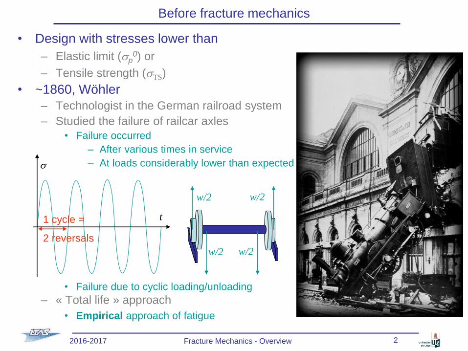
• Design with stresses lower than
– Elastic limit (sp0) or
– Tensile strength (sTS)
• ~1860, Wöhler
– Technologist in the German railroad system
– Studied the failure of railcar axles
• Failure occurred
– After various times in service
– At loads considerably lower than expected
• Failure due to cyclic loading/unloading
– « Total life » approach
• Empirical approach of fatigue
w/2 w/2
w/2 w/2
t
s
1 cycle =
2 reversals
2016-2017 Fracture Mechanics - Overview 2
Page 3
Before fracture mechanics
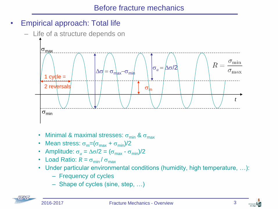
• Empirical approach: Total life
– Life of a structure depends on
• Minimal & maximal stresses: smin & smax
• Mean stress: sm=(smax + smin)/2
• Amplitude: sa = Ds/2 = (smax - smin)/2
• Load Ratio: R = smin / smax
• Under particular environmental conditions (humidity, high temperature, …):
– Frequency of cycles
– Shape of cycles (sine, step, …)
t
smax
smin
Ds = smax-smin
sa = Ds/2
sm
1 cycle =
2 reversals
2016-2017 Fracture Mechanics - Overview 3
Page 4
Before fracture mechanics
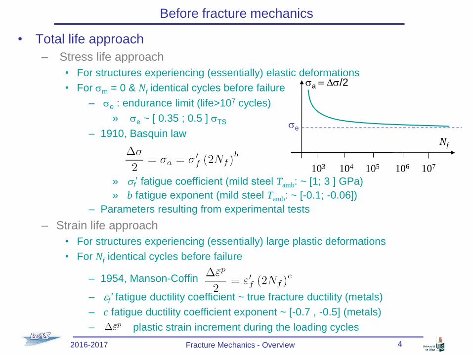
• Total life approach
– Stress life approach
• For structures experiencing (essentially) elastic deformations
• For sm = 0 & Nf identical cycles before failure
– se : endurance limit (life>107 cycles)
» se ~ [ 0.35 ; 0.5 ] sTS
– 1910, Basquin law
» sf’ fatigue coefficient (mild steel Tamb: ~ [1; 3 ] GPa)
» b fatigue exponent (mild steel Tamb: ~ [-0.1; -0.06])
– Parameters resulting from experimental tests
– Strain life approach
• For structures experiencing (essentially) large plastic deformations
• For Nf identical cycles before failure
– 1954, Manson-Coffin
– ef’ fatigue ductility coefficient ~ true fracture ductility (metals)
– c fatigue ductility coefficient exponent ~ [-0.7 , -0.5] (metals)
– plastic strain increment during the loading cycles
Nf
se
sa = Ds/2
103 104 105 106 107
2016-2017 Fracture Mechanics - Overview 4
Page 5
Design using total life approach
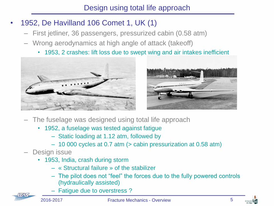
• 1952, De Havilland 106 Comet 1, UK (1)
– First jetliner, 36 passengers, pressurized cabin (0.58 atm)
– Wrong aerodynamics at high angle of attack (takeoff)
• 1953, 2 crashes: lift loss due to swept wing and air intakes inefficient
– The fuselage was designed using total life approach
• 1952, a fuselage was tested against fatigue
– Static loading at 1.12 atm, followed by
– 10 000 cycles at 0.7 atm (> cabin pressurization at 0.58 atm)
– Design issue• 1953, India, crash during storm
– « Structural failure » of the stabilizer
– The pilot does not “feel” the forces due to the fully powered controls (hydraulically assisted)
– Fatigue due to overstress ?
2016-2017 Fracture Mechanics - Overview 5
Page 6
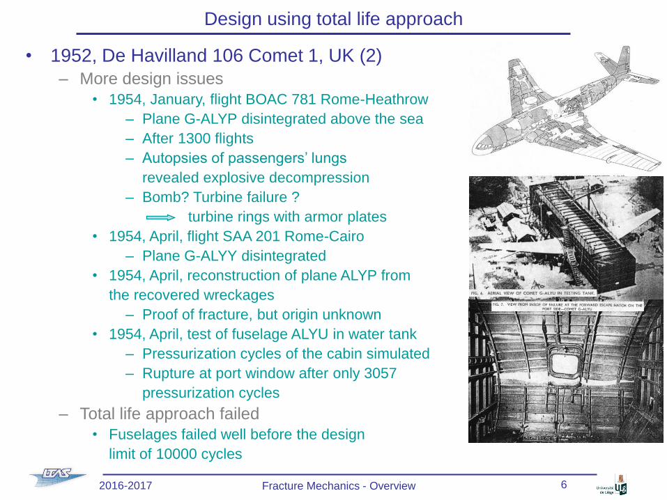
• 1952, De Havilland 106 Comet 1, UK (2)
– More design issues
• 1954, January, flight BOAC 781 Rome-Heathrow
– Plane G-ALYP disintegrated above the sea
– After 1300 flights
– Autopsies of passengers’ lungs
revealed explosive decompression
– Bomb? Turbine failure ?
turbine rings with armor plates
• 1954, April, flight SAA 201 Rome-Cairo
– Plane G-ALYY disintegrated
• 1954, April, reconstruction of plane ALYP from
the recovered wreckages
– Proof of fracture, but origin unknown
• 1954, April, test of fuselage ALYU in water tank
– Pressurization cycles of the cabin simulated
– Rupture at port window after only 3057
pressurization cycles
– Total life approach failed
• Fuselages failed well before the design
limit of 10000 cycles
Design using total life approach
2016-2017 Fracture Mechanics - Overview 6
Page 7
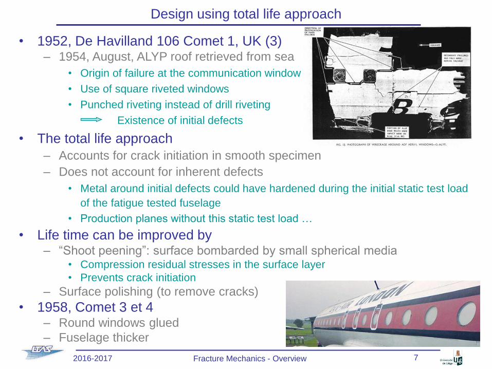
• 1952, De Havilland 106 Comet 1, UK (3)– 1954, August, ALYP roof retrieved from sea
• Origin of failure at the communication window
• Use of square riveted windows
• Punched riveting instead of drill riveting
Existence of initial defects
• The total life approach
– Accounts for crack initiation in smooth specimen
– Does not account for inherent defects
• Metal around initial defects could have hardened during the initial static test load
of the fatigue tested fuselage
• Production planes without this static test load …
• Life time can be improved by – “Shoot peening”: surface bombarded by small spherical media
• Compression residual stresses in the surface layer
• Prevents crack initiation
– Surface polishing (to remove cracks)
• 1958, Comet 3 et 4 – Round windows glued
– Fuselage thicker
Design using total life approach
2016-2017 Fracture Mechanics - Overview 7
Page 8
What is fracture mechanics ?
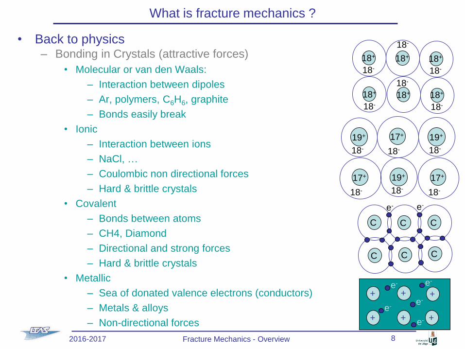
• Back to physics– Bonding in Crystals (attractive forces)
• Molecular or van den Waals:
– Interaction between dipoles
– Ar, polymers, C6H6, graphite
– Bonds easily break
• Ionic
– Interaction between ions
– NaCl, …
– Coulombic non directional forces
– Hard & brittle crystals
• Covalent
– Bonds between atoms
– CH4, Diamond
– Directional and strong forces
– Hard & brittle crystals
• Metallic
– Sea of donated valence electrons (conductors)
– Metals & alloys
– Non-directional forces
19+
18-
17+
18-
19+
18-
19+
18-
17+
18-
17+
18-
18+
18-
18+
18-
18+
18-
18+
18-
18+
18-
18+
18-
e- e-
C C C
C C C
+e-
+
+
+
+
+e-
e- e-
e-
2016-2017 Fracture Mechanics - Overview 8
Page 9
What is fracture mechanics ?
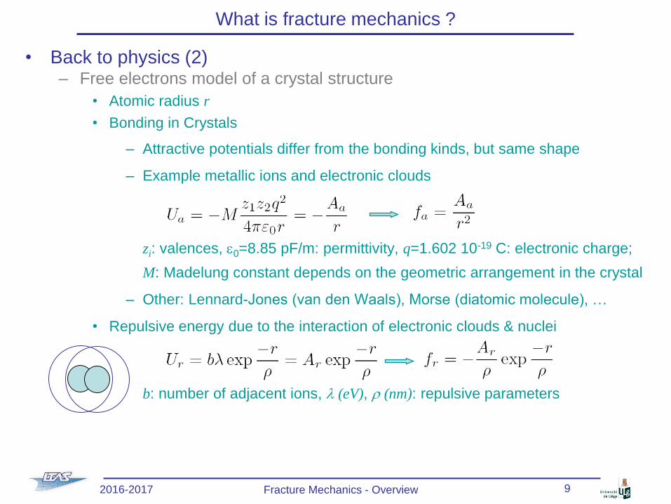
• Back to physics (2)– Free electrons model of a crystal structure
• Atomic radius r
• Bonding in Crystals
– Attractive potentials differ from the bonding kinds, but same shape
– Example metallic ions and electronic clouds
zi: valences, e0=8.85 pF/m: permittivity, q=1.602 10-19 C: electronic charge;
M: Madelung constant depends on the geometric arrangement in the crystal
– Other: Lennard-Jones (van den Waals), Morse (diatomic molecule), …
• Repulsive energy due to the interaction of electronic clouds & nuclei
b: number of adjacent ions, l (eV), r (nm): repulsive parameters
2016-2017 Fracture Mechanics - Overview 9
Page 10
What is fracture mechanics ?
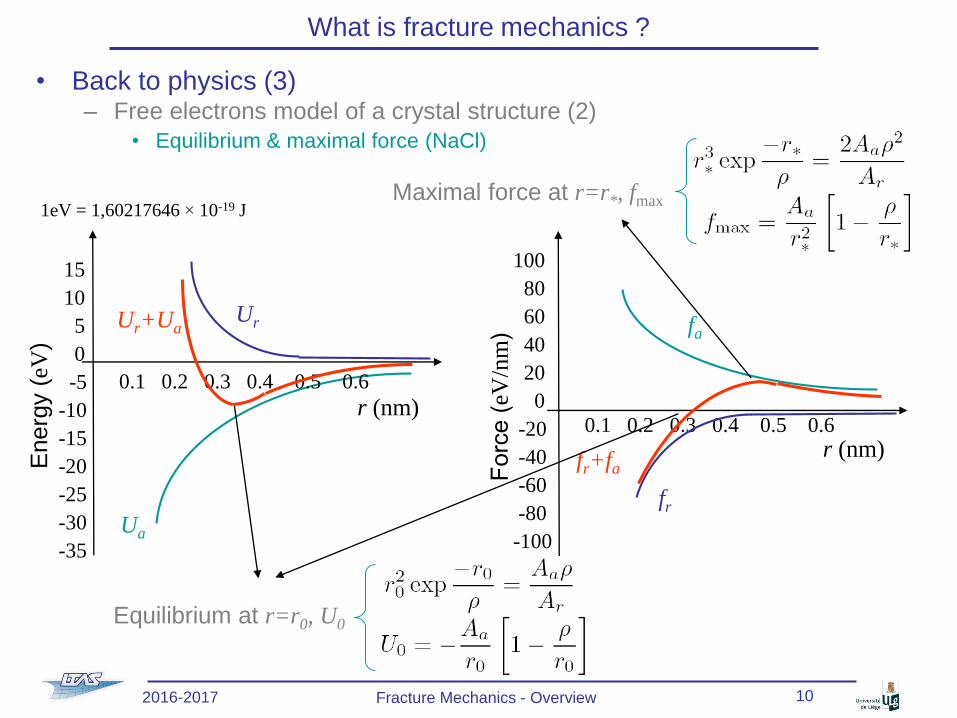
• Back to physics (3)– Free electrons model of a crystal structure (2)
• Equilibrium & maximal force (NaCl)
Ua
Energ
y (
eV)
r (nm)
15
10
5
0
-5
-10
-15
-20
-25
-30
-35
0.1 0.2 0.3 0.4 0.5 0.6
UrUr+Ua fa
Forc
e (
eV/n
m)
r (nm)
100
80
60
40
20
0
-20
-40
-60
-80
-100
0.1 0.2 0.3 0.4 0.5 0.6
fr
fr+fa
Equilibrium at r=r0, U0
Maximal force at r=r*, fmax1eV = 1,60217646 × 10⁻¹⁹ J
2016-2017 Fracture Mechanics - Overview 10
Page 11
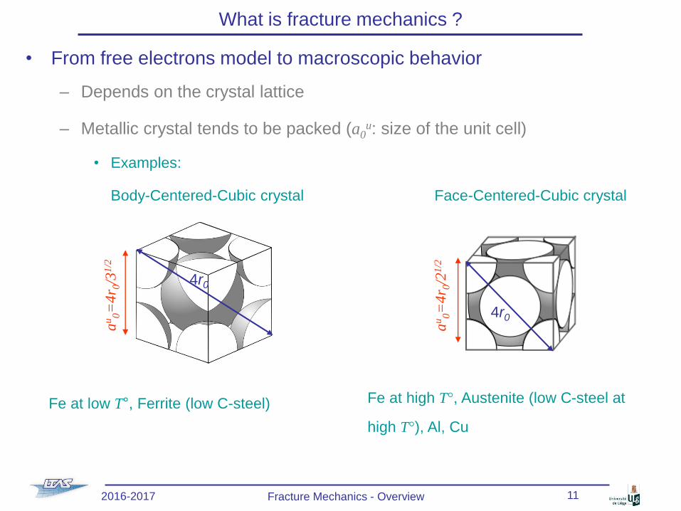
• From free electrons model to macroscopic behavior
– Depends on the crystal lattice
– Metallic crystal tends to be packed (a0u: size of the unit cell)
• Examples:
Body-Centered-Cubic crystal Face-Centered-Cubic crystal
What is fracture mechanics ?
4r0
au
0=
4r 0
/21
/2
Fe at low T°, Ferrite (low C-steel) Fe at high T°, Austenite (low C-steel at
high T°), Al, Cu
2016-2017 Fracture Mechanics - Overview 11
au
0=
4r 0
/31
/2
4r0
Page 12
What is fracture mechanics ?
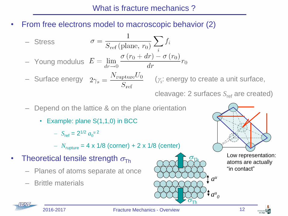
• From free electrons model to macroscopic behavior (2)
– Stress
– Young modulus
– Surface energy (gs: energy to create a unit surface,
cleavage: 2 surfaces Sref are created)
– Depend on the lattice & on the plane orientation
• Example: plane S(1,1,0) in BCC
– Sref = 21/2 a0u 2
– Nrupture = 4 x 1/8 (corner) + 2 x 1/8 (center)
• Theoretical tensile strength sTh
– Planes of atoms separate at once
– Brittle materials
sTh
sTh
au0
au
Low representation:
atoms are actually
“in contact”
2016-2017 Fracture Mechanics - Overview 12
Page 13
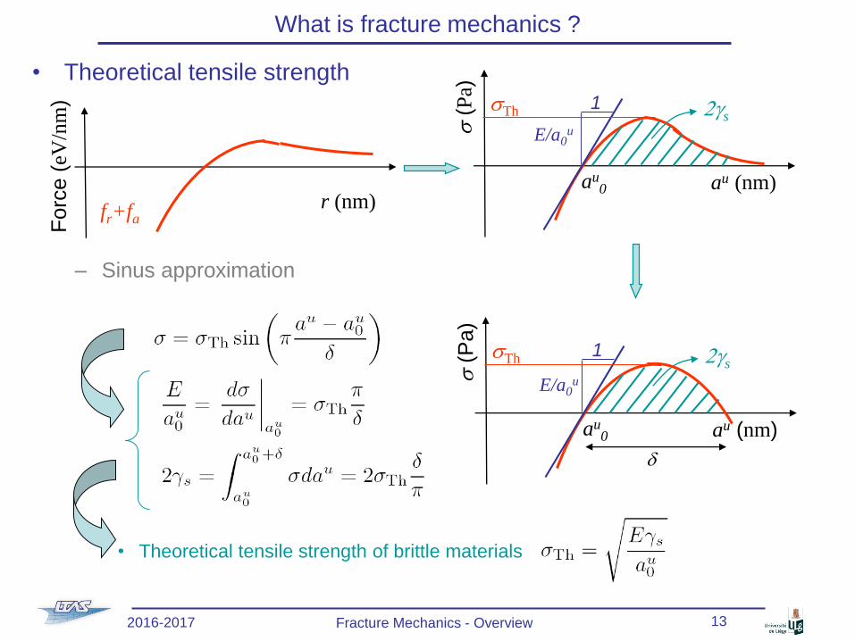
What is fracture mechanics ?
• Theoretical tensile strength
– Sinus approximation
• Theoretical tensile strength of brittle materials
Forc
e (
eV/n
m)
r (nm)fr+fa
s(P
a)
au (nm)
1
E/a0u
sTh
au0
2gs
s(P
a)
au (nm)
1sTh
au0
2gs
d
E/a0u
2016-2017 Fracture Mechanics - Overview 13
Page 14
What is fracture mechanics ?
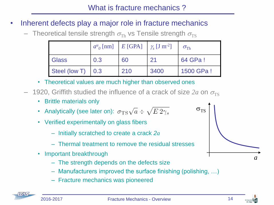
• Inherent defects play a major role in fracture mechanics
– Theoretical tensile strength sTh vs Tensile strength sTS
• Theoretical values are much higher than observed ones
– 1920, Griffith studied the influence of a crack of size 2a on sTS
• Brittle materials only
• Analytically (see later on):
• Verified experimentally on glass fibers
– Initially scratched to create a crack 2a
– Thermal treatment to remove the residual stresses
• Important breakthrough
– The strength depends on the defects size
– Manufacturers improved the surface finishing (polishing, …)
– Fracture mechanics was pioneered
au0 [nm] E [GPA] gs [J m-2] sTh
Glass 0.3 60 21 64 GPa !
Steel (low T) 0.3 210 3400 1500 GPa !
sTS
a
2016-2017 Fracture Mechanics - Overview 14
Page 15
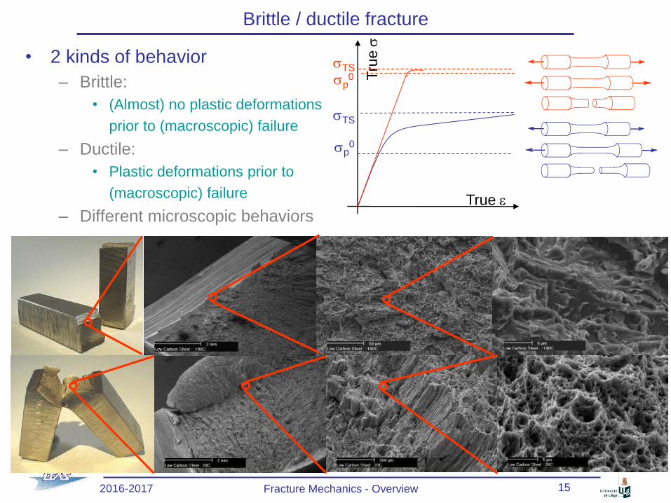
Brittle / ductile fracture
• 2 kinds of behavior
– Brittle:
• (Almost) no plastic deformations
prior to (macroscopic) failure
– Ductile:
• Plastic deformations prior to
(macroscopic) failure
– Different microscopic behaviorsTrue e
Tru
es
sTS
sp0
sTS
sp0
2016-2017 Fracture Mechanics - Overview 15
Page 16
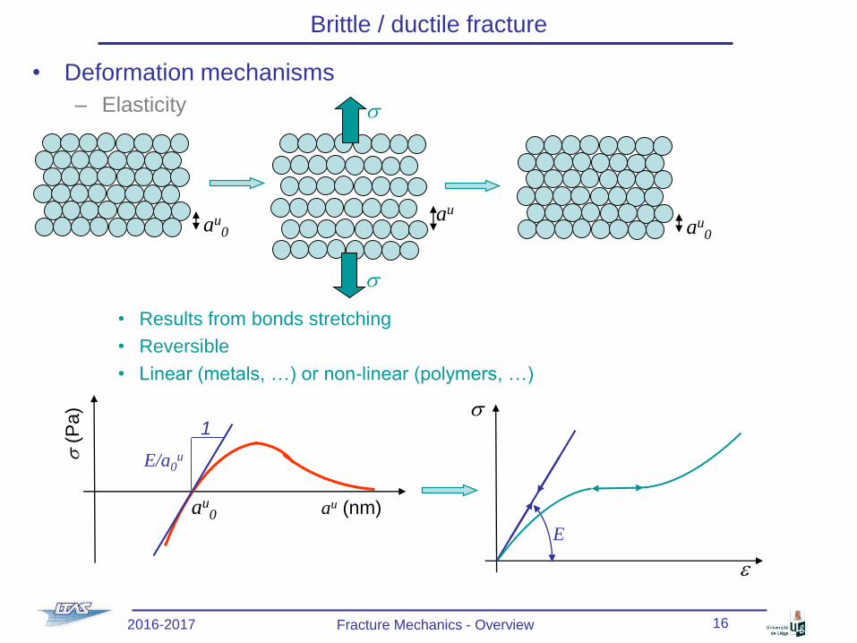
Brittle / ductile fracture
• Deformation mechanisms
– Elasticity
• Results from bonds stretching
• Reversible
• Linear (metals, …) or non-linear (polymers, …)
au0
s
s
au
au0
s(P
a)
au (nm)
1
E/a0u
au0
s
e
E
2016-2017 Fracture Mechanics - Overview 16
Page 17
Brittle / ductile fracture
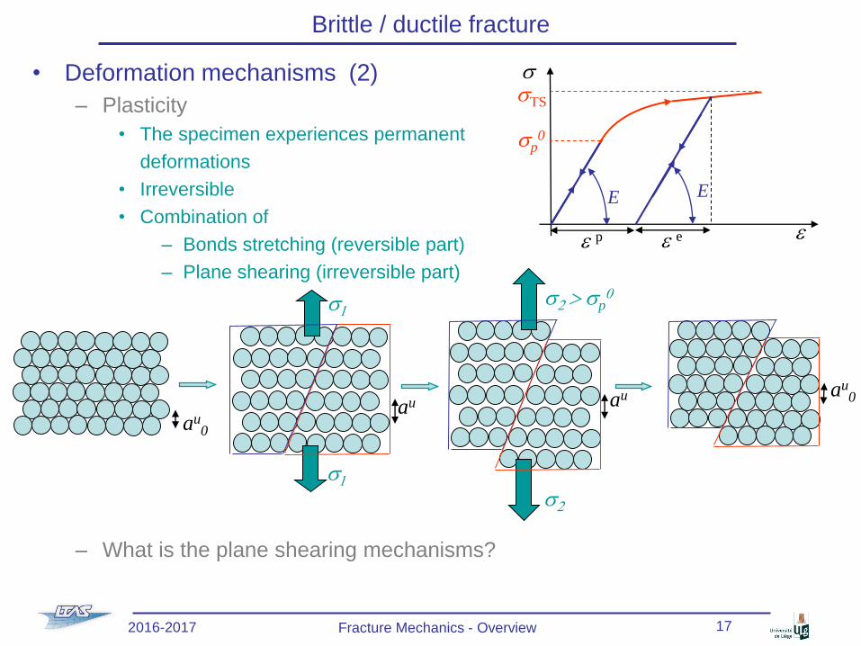
• Deformation mechanisms (2)
– Plasticity
• The specimen experiences permanent
deformations
• Irreversible
• Combination of
– Bonds stretching (reversible part)
– Plane shearing (irreversible part)
– What is the plane shearing mechanisms?
au0
s
e
E E
sTS
sp0
e p e e
au
s2 > sp0
s2
s1
s1
auau
0
2016-2017 Fracture Mechanics - Overview 17
Page 18
Brittle / ductile fracture
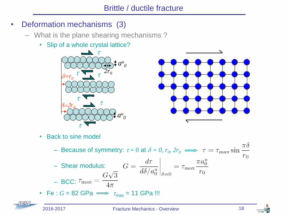
• Deformation mechanisms (3)
– What is the plane shearing mechanisms ?
• Slip of a whole crystal lattice?
• Back to sine model
– Because of symmetry: t = 0 at d = 0, r0, 2r0
– Shear modulus:
– BCC:
• Fe : G = 82 GPa tmax = 11 GPa !!!
2016-2017 Fracture Mechanics - Overview 18
td=r0
t
t
t
au0
2r0
t
t
au0
d=2r0
Page 19
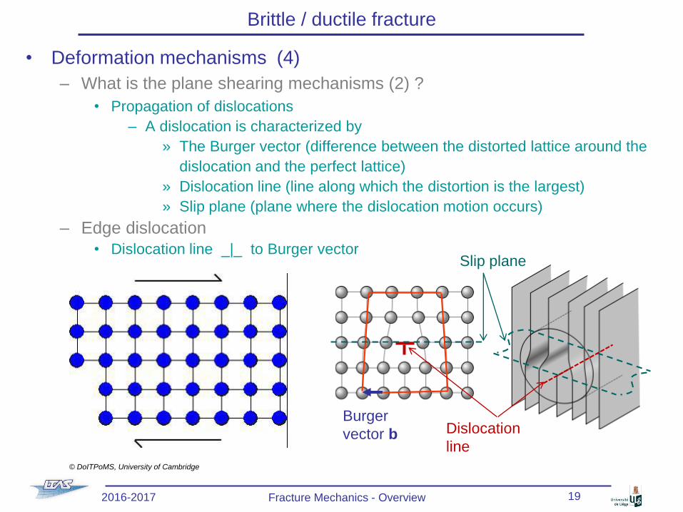
• Deformation mechanisms (4)
– What is the plane shearing mechanisms (2) ?
• Propagation of dislocations
– A dislocation is characterized by
» The Burger vector (difference between the distorted lattice around the
dislocation and the perfect lattice)
» Dislocation line (line along which the distortion is the largest)
» Slip plane (plane where the dislocation motion occurs)
– Edge dislocation
• Dislocation line _|_ to Burger vector
Brittle / ductile fracture
© DoITPoMS, University of Cambridge
2016-2017 Fracture Mechanics - Overview 19
Slip plane
Burger
vector b Dislocation
line
Page 20
Brittle / ductile fracture
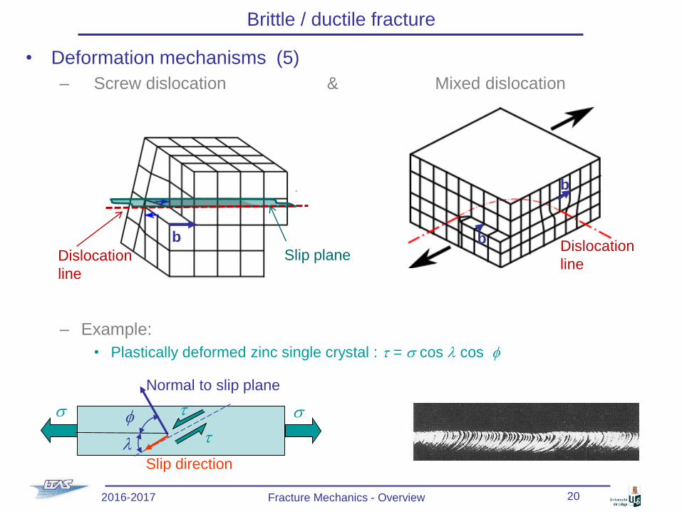
• Deformation mechanisms (5)
– Screw dislocation & Mixed dislocation
– Example:
• Plastically deformed zinc single crystal : t = s cos l cos f
ss t
tf
l
Normal to slip plane
Slip direction
2016-2017 Fracture Mechanics - Overview 20
Slip plane
b
Dislocation
line
Dislocation
line
b
b
Page 21
Brittle / ductile fracture
• Dislocations and brittle/ductile materials
– Cristal with ionic bonding (NaCl, …)
• Motion of dislocations difficult
– A + would be in front of another +
– Cleavage before brittle
– Covalent bonding (Si, diamond, …)
• Motion of dislocations difficult
– Strong & directional bonding
– Cleavage before brittle
– Metallic bonding
• Motion of dislocations possible
– Non directional bonding
• Motion along packed slip directions
– Brittle or ductile?
+
-
+
-
+
-
+
-
+
-
+
-
C C C
C C C
+e-
+
+
+
+
+e-
e- e-
e-
BCC:
6 slip planes
X 2 directions=
12 slip systems
FCC:
4 slip planes
X 3 directions=
12 slip systems
2016-2017 Fracture Mechanics - Overview 21
Page 22
Brittle / ductile fracture
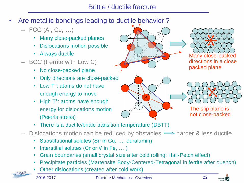
• Are metallic bondings leading to ductile behavior ?
– FCC (Al, Cu, …)
• Many close-packed planes
• Dislocations motion possible
• Always ductile
– BCC (Ferrite with Low C)
• No close-packed plane
• Only directions are close-packed
• Low T°: atoms do not have
enough energy to move
• High T°: atoms have enough
energy for dislocations motion
(Peierls stress)
• There is a ductile/brittle transition temperature (DBTT)
– Dislocations motion can be reduced by obstacles harder & less ductile
• Substitutional solutes (Sn in Cu, …, duralumin)
• Interstitial solutes (Cr or V in Fe, … )
• Grain boundaries (small crystal size after cold rolling: Hall-Petch effect)
• Precipitate particles (Martensite Body-Centered-Tetragonal in ferrite after quench)
• Other dislocations (created after cold work)
Many close-packed directions in a close packed plane
The slip plane is not close-packed
2016-2017 Fracture Mechanics - Overview 22
Page 23
Brittle / ductile fracture
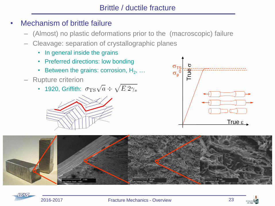
• Mechanism of brittle failure
– (Almost) no plastic deformations prior to the (macroscopic) failure
– Cleavage: separation of crystallographic planes
• In general inside the grains
• Preferred directions: low bonding
• Between the grains: corrosion, H2, …
– Rupture criterion
• 1920, Griffith:
True e
Tru
essTS
sp0
2016-2017 Fracture Mechanics - Overview 23
Page 24
Brittle / ductile fracture
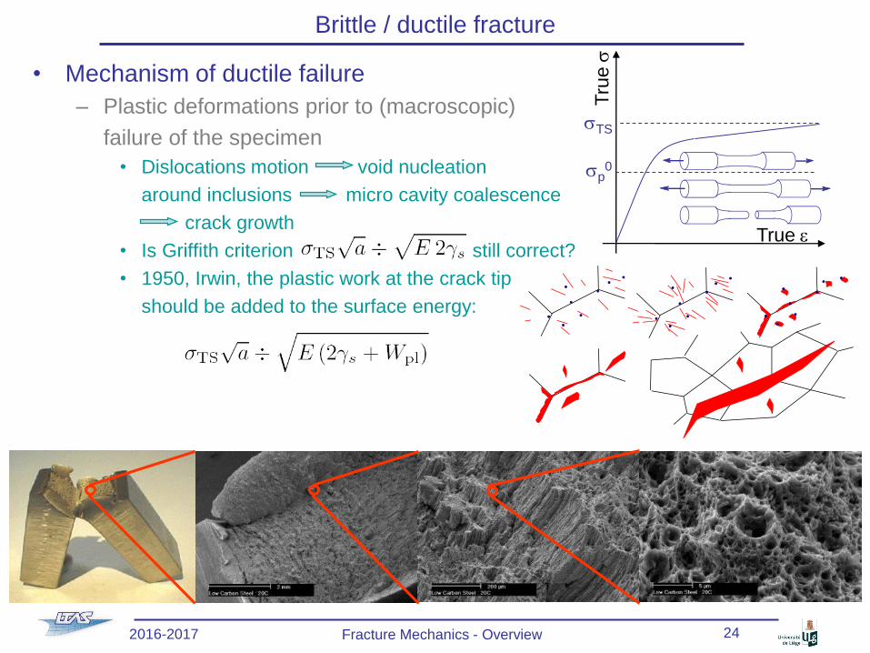
• Mechanism of ductile failure
– Plastic deformations prior to (macroscopic)
failure of the specimen
• Dislocations motion void nucleation
around inclusions micro cavity coalescence
crack growth
• Is Griffith criterion still correct?
• 1950, Irwin, the plastic work at the crack tip
should be added to the surface energy:
True e
Tru
es
sTS
sp0
2016-2017 Fracture Mechanics - Overview 24
Page 25
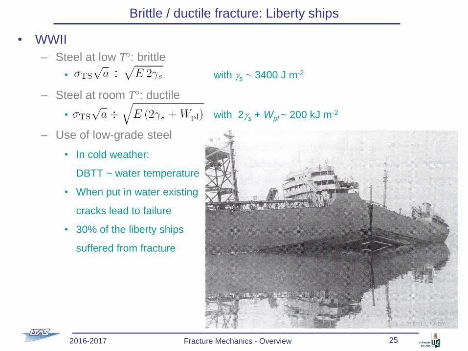
Brittle / ductile fracture: Liberty ships
• WWII
– Steel at low T°: brittle
• with gs ~ 3400 J m-2
– Steel at room T°: ductile
• with 2gs + Wpl ~ 200 kJ m-2
– Use of low-grade steel
• In cold weather:
DBTT ~ water temperature
• When put in water existing
cracks lead to failure
• 30% of the liberty ships
suffered from fracture
2016-2017 Fracture Mechanics - Overview 25
Page 26
Brittle / ductile fracture
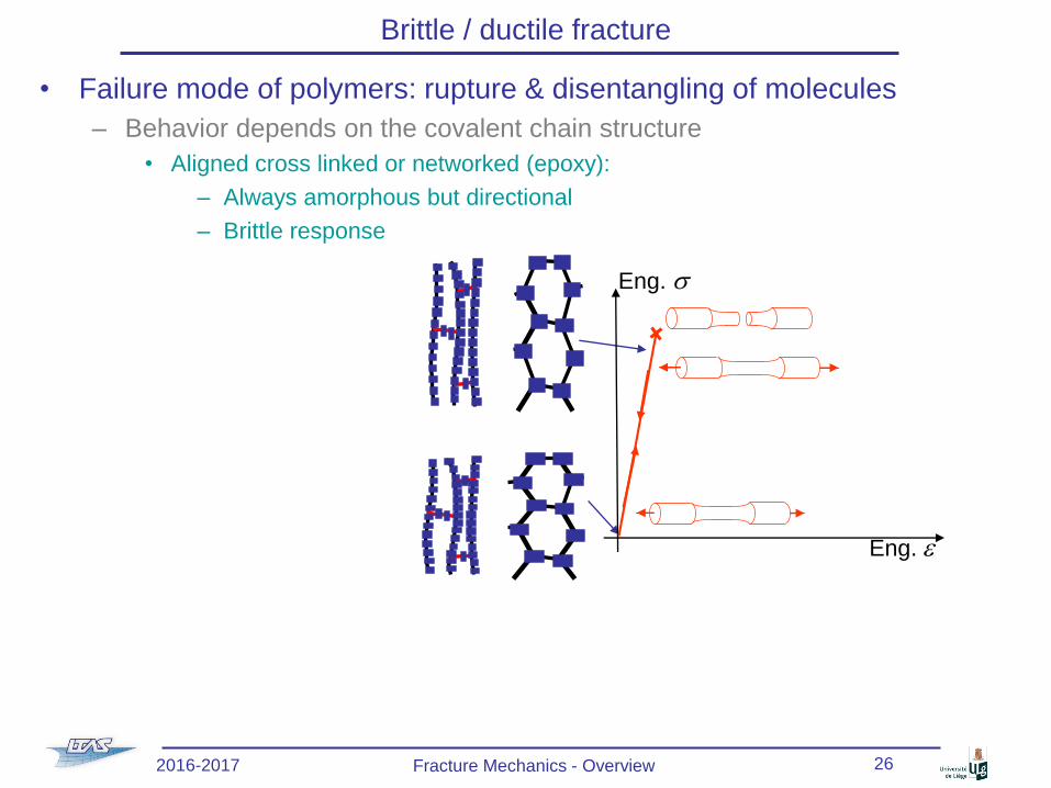
• Failure mode of polymers: rupture & disentangling of molecules
– Behavior depends on the covalent chain structure
• Aligned cross linked or networked (epoxy):
– Always amorphous but directional
– Brittle response
Eng. s
Eng. e
2016-2017 Fracture Mechanics - Overview 26
Page 27
Brittle / ductile fracture
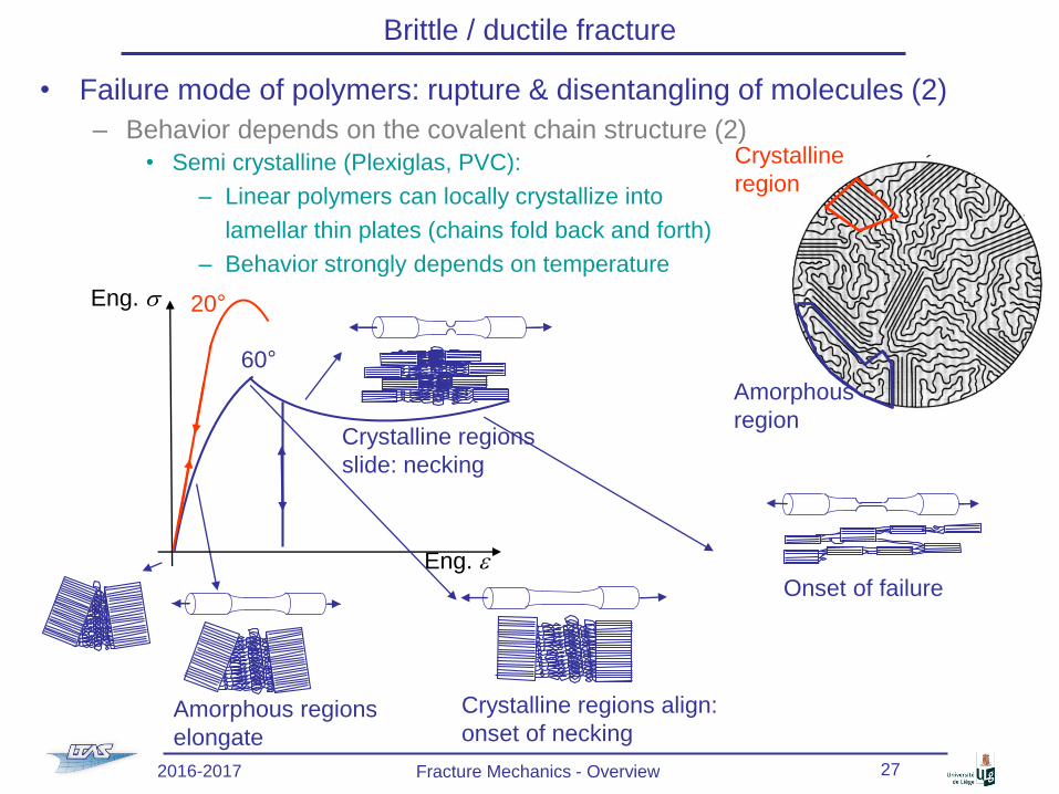
• Failure mode of polymers: rupture & disentangling of molecules (2)
– Behavior depends on the covalent chain structure (2)
• Semi crystalline (Plexiglas, PVC):
– Linear polymers can locally crystallize into
lamellar thin plates (chains fold back and forth)
– Behavior strongly depends on temperature
Crystalline
region
Amorphous
region
Eng. s
Eng. e
20°
60°
Amorphous regions
elongate
Crystalline regions align:
onset of necking
Crystalline regions
slide: necking
Onset of failure
2016-2017 Fracture Mechanics - Overview 27
Page 28
Brittle / ductile fracture
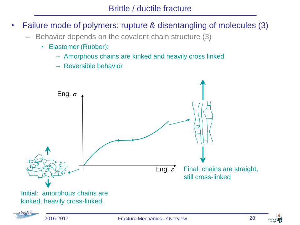
• Failure mode of polymers: rupture & disentangling of molecules (3)
– Behavior depends on the covalent chain structure (3)
• Elastomer (Rubber):
– Amorphous chains are kinked and heavily cross linked
– Reversible behavior
Eng. s
Eng. e
Initial: amorphous chains are
kinked, heavily cross-linked.
Final: chains are straight,
still cross-linked
2016-2017 Fracture Mechanics - Overview 28
Page 29
Brittle / ductile fracture
• Composites
– Fibers in a matrix
• Fibers: polymers, metals or ceramics
• Matrix: polymers, metals or ceramics
• Fibers orientation: unidirectional, woven,
random
– Complex failure modes
• Transverse matrix fracture
• Longitudinal matrix fracture
• Fiber rupture
• Fiber debonding
• Delamination
• Macroscopically: no
plastic deformation
2016-2017 Fracture Mechanics - Overview 29
Delamination
Matrix
rupture
Pull out
Bridging
Fiber rupture
Debonding
Page 30
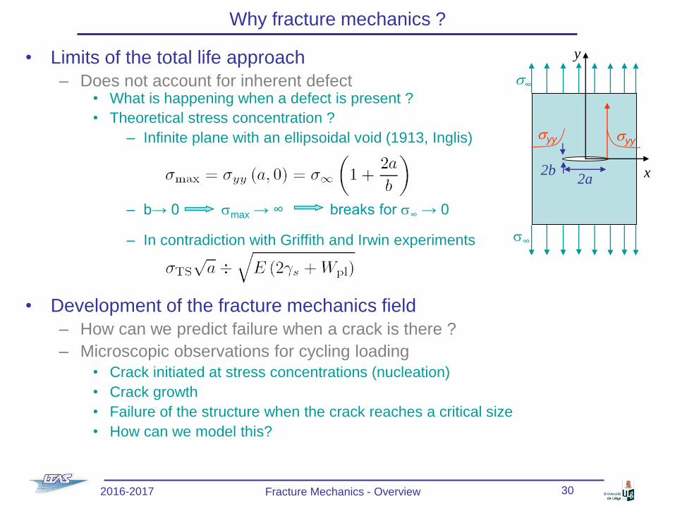
Why fracture mechanics ?
• Limits of the total life approach
– Does not account for inherent defect• What is happening when a defect is present ?
• Theoretical stress concentration ?
– Infinite plane with an ellipsoidal void (1913, Inglis)
– b→ 0 smax → ∞ breaks for s∞ → 0
– In contradiction with Griffith and Irwin experiments
• Development of the fracture mechanics field
– How can we predict failure when a crack is there ?
– Microscopic observations for cycling loading
• Crack initiated at stress concentrations (nucleation)
• Crack growth
• Failure of the structure when the crack reaches a critical size
• How can we model this?
2a2b x
y
s∞
s∞
syysyy
2016-2017 Fracture Mechanics - Overview 30
Page 31
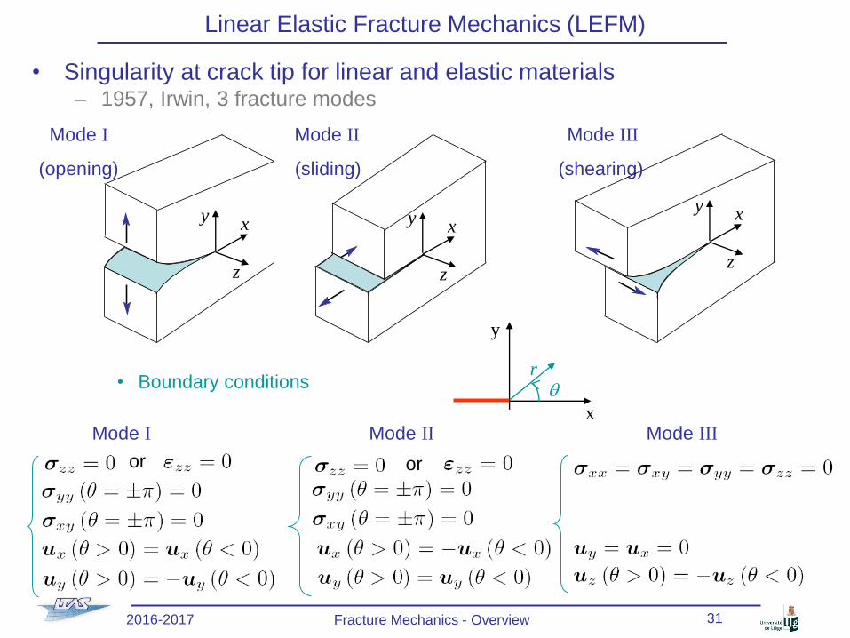
Linear Elastic Fracture Mechanics (LEFM)
• Singularity at crack tip for linear and elastic materials– 1957, Irwin, 3 fracture modes
• Boundary conditions
Mode I Mode II Mode III
(opening) (sliding) (shearing)
y
x
rq
Mode I Mode II Mode III
or or
y x
z
y x
z
y x
z
2016-2017 Fracture Mechanics - Overview 31
Page 32
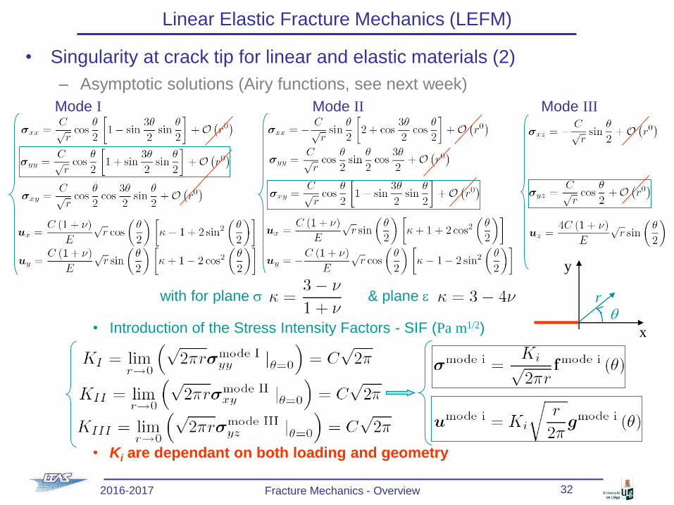
• Singularity at crack tip for linear and elastic materials (2)
– Asymptotic solutions (Airy functions, see next week)
with for plane s & plane e
• Introduction of the Stress Intensity Factors - SIF (Pa m1/2)
• Ki are dependant on both loading and geometry
Linear Elastic Fracture Mechanics (LEFM)
y
x
rq
Mode I Mode II Mode III
2016-2017 Fracture Mechanics - Overview 32
Page 33
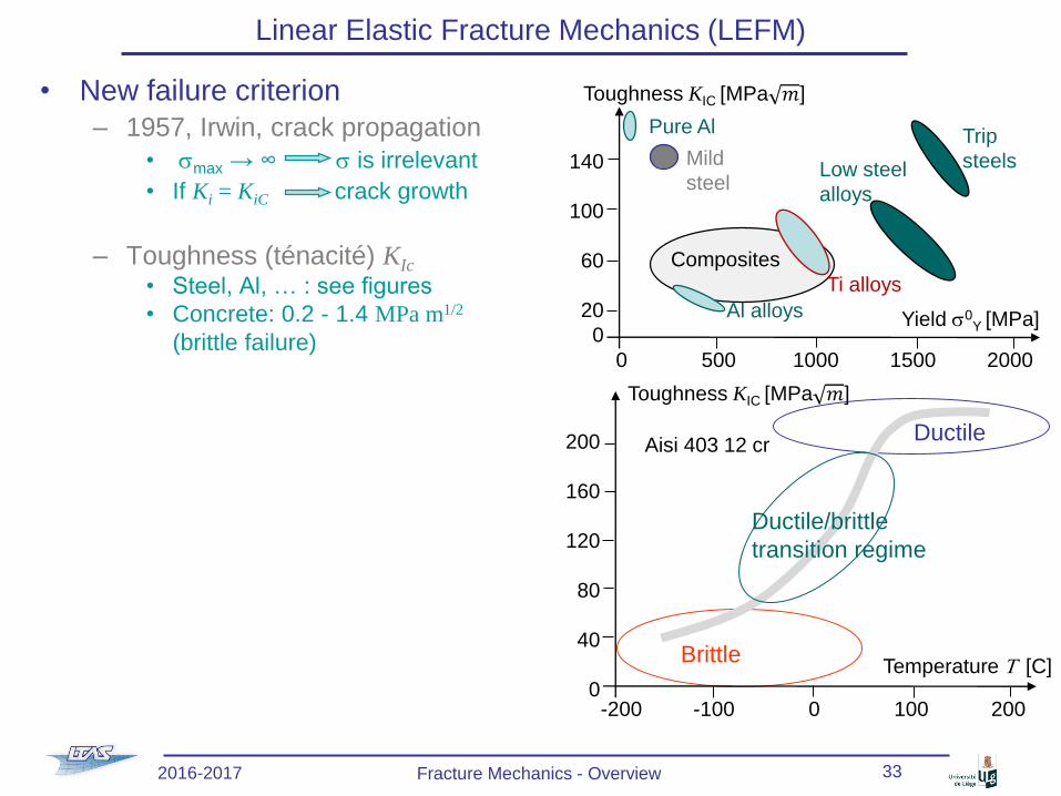
• New failure criterion
– 1957, Irwin, crack propagation
• smax → ∞ s is irrelevant
• If Ki = KiC crack growth
– Toughness (ténacité) KIc
• Steel, Al, … : see figures
• Concrete: 0.2 - 1.4 MPa m1/2
(brittle failure)
Linear Elastic Fracture Mechanics (LEFM)
2016-2017 Fracture Mechanics - Overview 33
Yield s0Y [MPa]
Toughness KIC [MPa 𝑚]
0 500 1000 1500 2000
140
100
60
20
0
Pure Al
Mild
steel Low steel
alloys
Trip
steels
Al alloys
Ti alloys
Composites
Aisi 403 12 cr
Brittle
Ductile
Temperature T [C]
Toughness KIC [MPa 𝑚]
-200 -100 0 100 200
200
160
120
80
40
0
Ductile/brittle
transition regime
Page 34
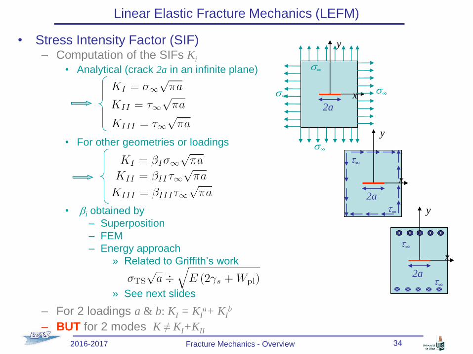
• Stress Intensity Factor (SIF)– Computation of the SIFs Ki
• Analytical (crack 2a in an infinite plane)
• For other geometries or loadings
• bi obtained by
– Superposition
– FEM
– Energy approach
» Related to Griffith’s work
» See next slides
– For 2 loadings a & b: KI = KIa+ KI
b
– BUT for 2 modes K ≠ KI+KII
Linear Elastic Fracture Mechanics (LEFM)
s∞s∞
y
2a
x
s∞
s∞
y
2a
x
t∞
t∞
y
2a
x
t∞
t∞
2016-2017 Fracture Mechanics - Overview 34
Page 35
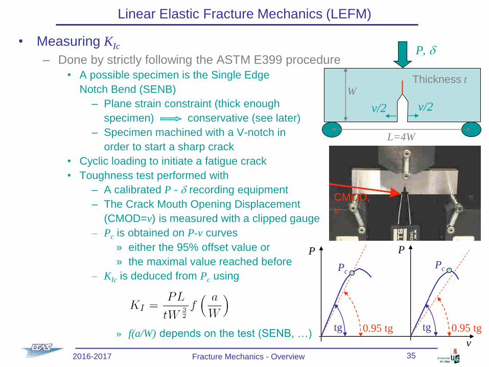
• Measuring KIc
– Done by strictly following the ASTM E399 procedure
• A possible specimen is the Single Edge
Notch Bend (SENB)
– Plane strain constraint (thick enough
specimen) conservative (see later)
– Specimen machined with a V-notch in
order to start a sharp crack
• Cyclic loading to initiate a fatigue crack
• Toughness test performed with
– A calibrated P - d recording equipment
– The Crack Mouth Opening Displacement
(CMOD=v) is measured with a clipped gauge
– Pc is obtained on P-v curves
» either the 95% offset value or
» the maximal value reached before
– KIc is deduced from Pc using
» f(a/W) depends on the test (SENB, …)
Linear Elastic Fracture Mechanics (LEFM)
P, d
v/2v/2
L=4W
WThickness t
CMOD,
v
v
P
tg 0.95 tg
Pc
P
tg 0.95 tg
Pc
2016-2017 Fracture Mechanics - Overview 35
Page 36
Linear Elastic Fracture Mechanics (LEFM)
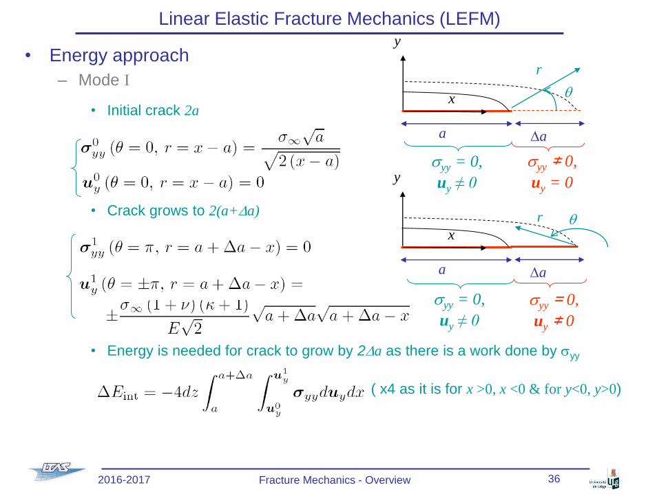
• Energy approach
– Mode I
• Initial crack 2a
• Crack grows to 2(a+Da)
• Energy is needed for crack to grow by 2Da as there is a work done by syy
( x4 as it is for x >0, x <0 & for y<0, y>0)
y
x
a Da
r
q
syy = 0,
uy ≠ 0
syy ≠ 0,
uy = 0y
x
a Da
r q
syy = 0,
uy ≠ 0
syy = 0,
uy ≠ 0
2016-2017 Fracture Mechanics - Overview 36
Page 37
Linear Elastic Fracture Mechanics (LEFM)
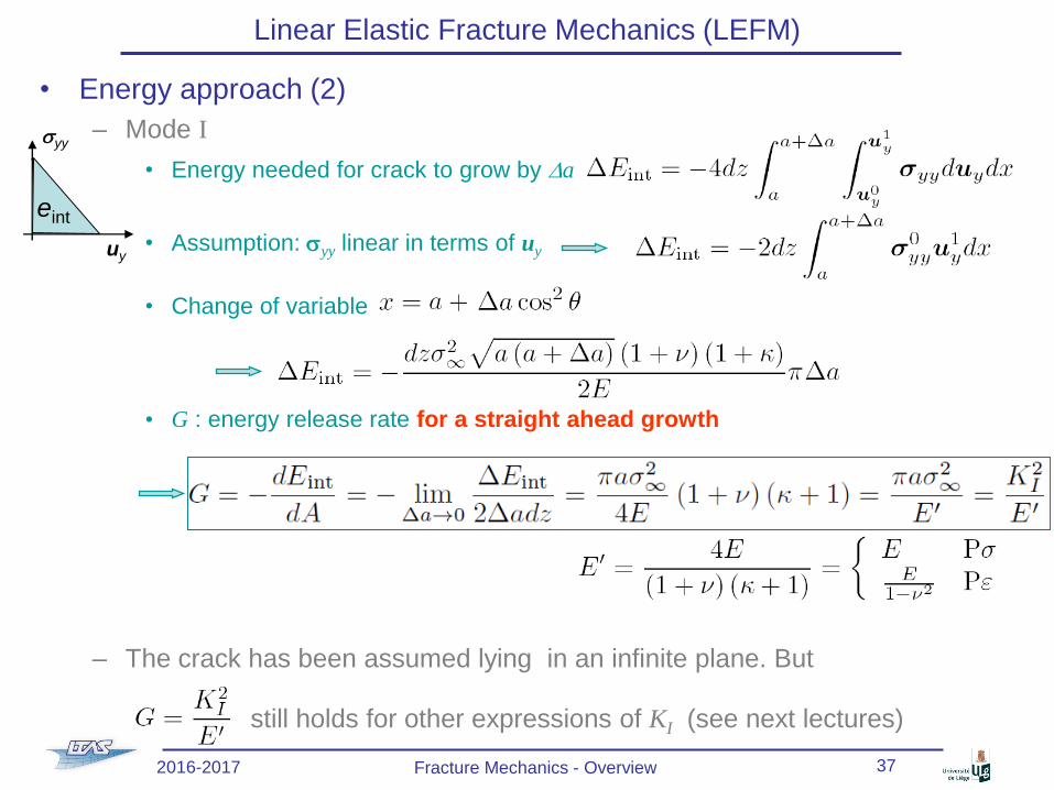
• Energy approach (2)
– Mode I
• Energy needed for crack to grow by Da
• Assumption: syy linear in terms of uy
• Change of variable
• G : energy release rate for a straight ahead growth
– The crack has been assumed lying in an infinite plane. But
still holds for other expressions of KI (see next lectures)
uy
syy
eint
2016-2017 Fracture Mechanics - Overview 37
Page 38
Linear Elastic Fracture Mechanics (LEFM)
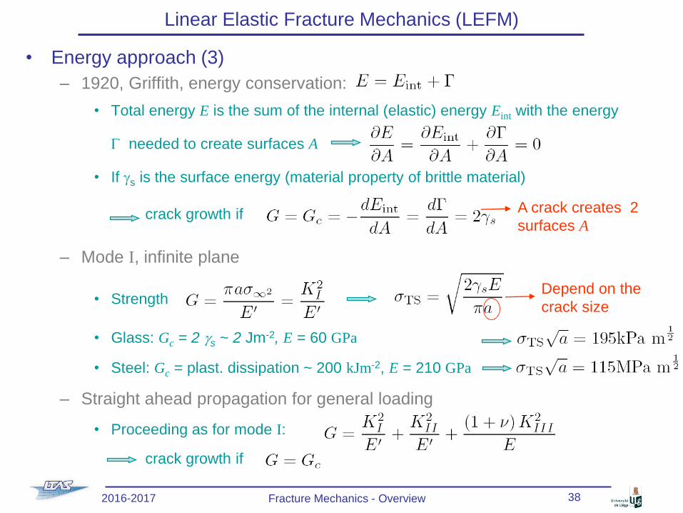
• Energy approach (3)
– 1920, Griffith, energy conservation:
• Total energy E is the sum of the internal (elastic) energy Eint with the energy
G needed to create surfaces A
• If gs is the surface energy (material property of brittle material)
crack growth if
– Mode I, infinite plane
• Strength
• Glass: Gc = 2 gs ~ 2 Jm-2, E = 60 GPa
• Steel: Gc = plast. dissipation ~ 200 kJm-2, E = 210 GPa
– Straight ahead propagation for general loading
• Proceeding as for mode I:
crack growth if
A crack creates 2
surfaces A
Depend on the
crack size
2016-2017 Fracture Mechanics - Overview 38
Page 39
Linear Elastic Fracture Mechanics (LEFM)
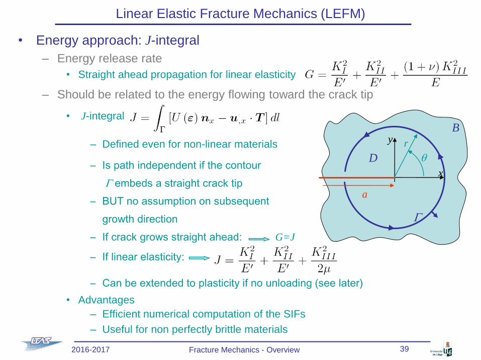
• Energy approach: J-integral
– Energy release rate
• Straight ahead propagation for linear elasticity
– Should be related to the energy flowing toward the crack tip
• J-integral
– Defined even for non-linear materials
– Is path independent if the contour
G embeds a straight crack tip
– BUT no assumption on subsequent
growth direction
– If crack grows straight ahead: G=J
– If linear elasticity:
– Can be extended to plasticity if no unloading (see later)
• Advantages
– Efficient numerical computation of the SIFs
– Useful for non perfectly brittle materials
x
yB
G
a
D
r
q
2016-2017 Fracture Mechanics - Overview 39
Page 40
Linear Elastic Fracture Mechanics (LEFM)
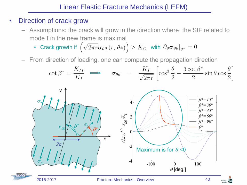
• Direction of crack grow
– Assumptions: the crack will grow in the direction where the SIF related to
mode I in the new frame is maximal
• Crack growth if with
– From direction of loading, one can compute the propagation direction
2ax
y
s∞
s∞
b*
q*er
reqq
2016-2017 Fracture Mechanics - Overview 40
-100 0 100-4
-2
0
2
4
q [°]
(2
r)1
/2 s
qq /
KI
b*=15°
b*=30°
b*=45°
b*=60°
b*=90°
q*
Maximum is for q <0
q [deg.]
Page 41
Linear Elastic Fracture Mechanics (LEFM)
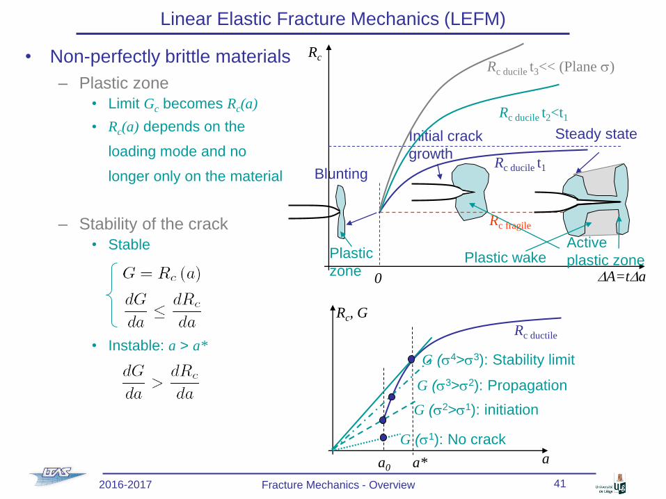
• Non-perfectly brittle materials
– Plastic zone
• Limit Gc becomes Rc(a)
• Rc(a) depends on the
loading mode and no
longer only on the material
– Stability of the crack
• Stable
• Instable: a > a*
a
Rc, G
Rc ductile
G (s2>s1): initiation
G (s1): No crack
a0 a*
G (s4>s3): Stability limit
G (s3>s2): Propagation
2016-2017 Fracture Mechanics - Overview 41
Plastic
zone
Blunting
Initial crack
growth
Steady state
DA=tDa
Rc
Rc fragile
Rc ducile t1
0
Rc ducile t2<t1
Rc ducile t3<< (Plane s)
Active
plastic zonePlastic wake
Page 42
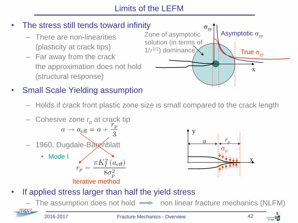
Limits of the LEFM
• The stress still tends toward infinity
– There are non-linearities
(plasticity at crack tips)
– Far away from the crack
the approximation does not hold
(structural response)
• Small Scale Yielding assumption
– Holds if crack front plastic zone size is small compared to the crack length
– Cohesive zone rp at crack tip
– 1960, Dugdale-Barenblatt
• Mode I
• If applied stress larger than half the yield stress
– The assumption does not hold non linear fracture mechanics (NLFM)
syy
x
Asymptotic syy
True syy
Zone of asymptotic
solution (in terms of
1/r1/2) dominance
asp
x
rp
y
Iterative method
2016-2017 Fracture Mechanics - Overview 42
Page 43
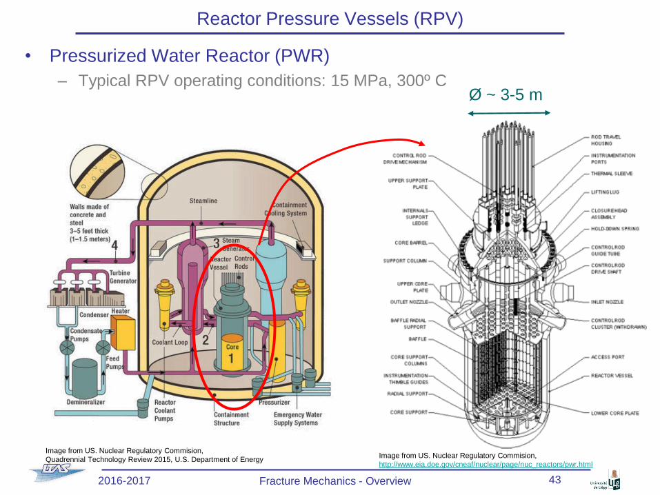
Reactor Pressure Vessels (RPV)
• Pressurized Water Reactor (PWR)
– Typical RPV operating conditions: 15 MPa, 300º C
2016-2017 Fracture Mechanics - Overview 43
Image from US. Nuclear Regulatory Commision,
Quadrennial Technology Review 2015, U.S. Department of EnergyImage from US. Nuclear Regulatory Commision,
http://www.eia.doe.gov/cneaf/nuclear/page/nuc_reactors/pwr.html
Ø ~ 3-5 m
Page 44
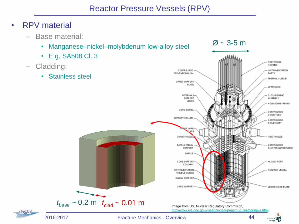
Reactor Pressure Vessels (RPV)
• RPV material
– Base material:
• Manganese–nickel–molybdenum low-alloy steel
• E.g. SA508 Cl. 3
– Cladding:
• Stainless steel
2016-2017 Fracture Mechanics - Overview 44
tbase ~ 0.2 m tclad ~ 0.01 m
44
Image from US. Nuclear Regulatory Commision,
http://www.eia.doe.gov/cneaf/nuclear/page/nuc_reactors/pwr.html
Ø ~ 3-5 m
Page 45
Reactor Pressure Vessels (RPV)
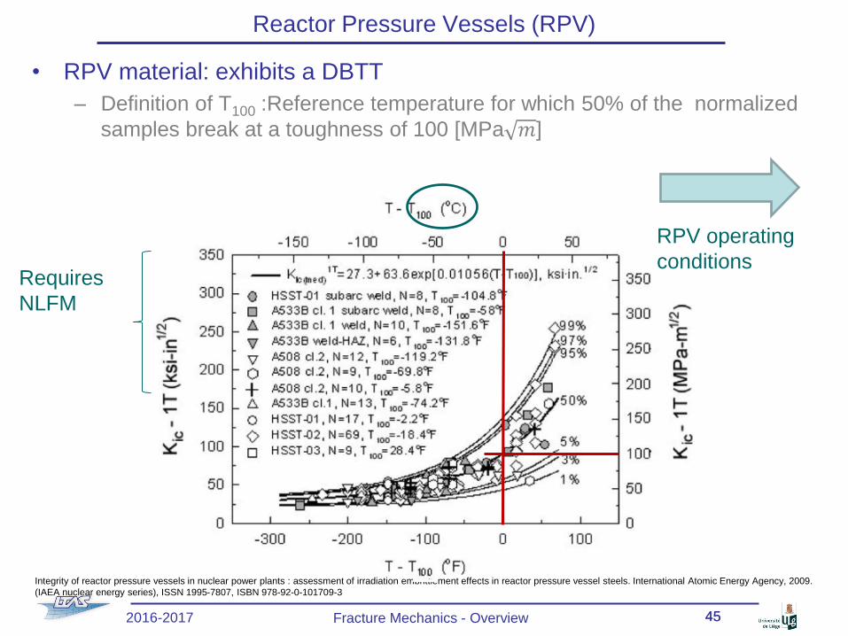
• RPV material: exhibits a DBTT
– Definition of T100 :Reference temperature for which 50% of the normalized
samples break at a toughness of 100 [MPa 𝑚]
2016-2017 Fracture Mechanics - Overview 4545
Integrity of reactor pressure vessels in nuclear power plants : assessment of irradiation embrittlement effects in reactor pressure vessel steels. International Atomic Energy Agency, 2009.
(IAEA nuclear energy series), ISSN 1995-7807, ISBN 978-92-0-101709-3
RPV operating
conditionsRequires
NLFM
Page 46
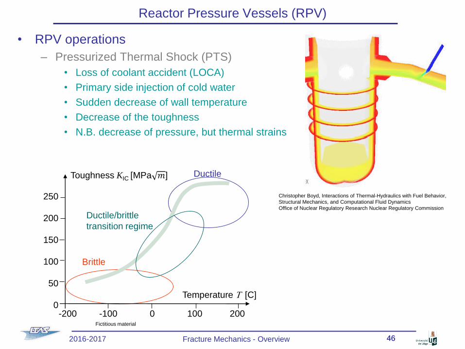
Reactor Pressure Vessels (RPV)
• RPV operations
– Pressurized Thermal Shock (PTS)
• Loss of coolant accident (LOCA)
• Primary side injection of cold water
• Sudden decrease of wall temperature
• Decrease of the toughness
• N.B. decrease of pressure, but thermal strains
2016-2017 Fracture Mechanics - Overview 4646
Christopher Boyd, Interactions of Thermal-Hydraulics with Fuel Behavior,
Structural Mechanics, and Computational Fluid Dynamics
Office of Nuclear Regulatory Research Nuclear Regulatory Commission
Brittle
Ductile
Temperature T [C]
Toughness KIC [MPa 𝑚]
-200 -100 0 100 200
250
200
150
100
50
0
Ductile/brittle
transition regime
Fictitious material
Page 47
Reactor Pressure Vessels (RPV)
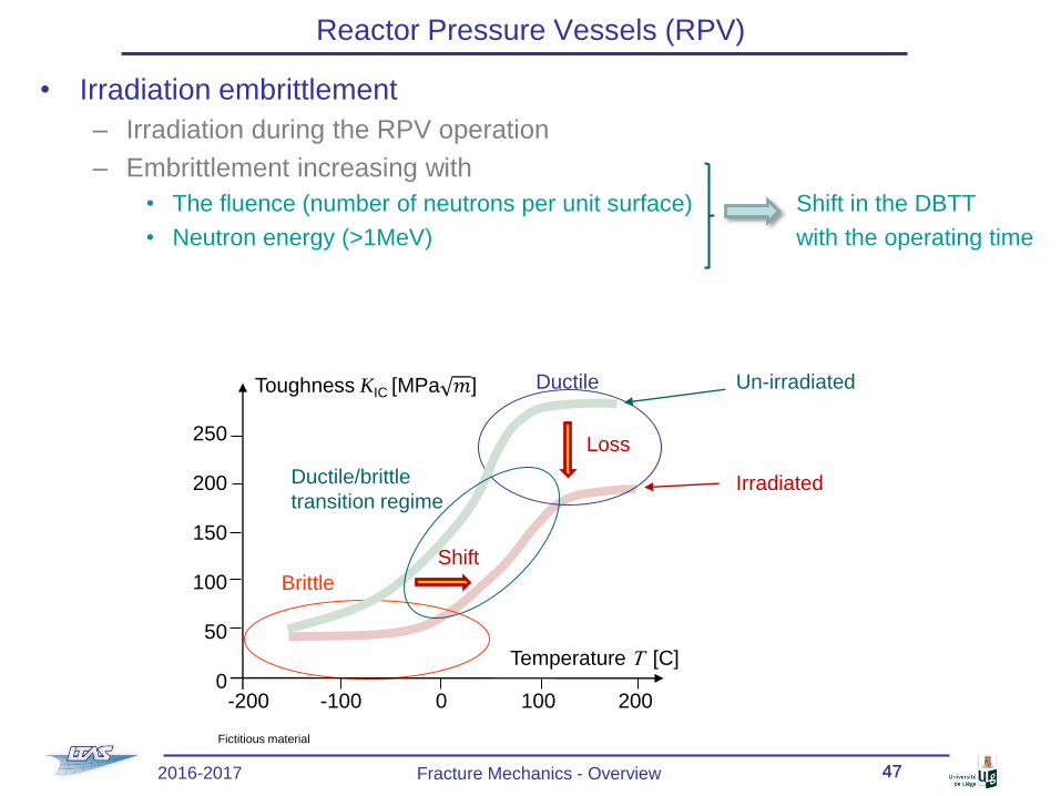
• Irradiation embrittlement
– Irradiation during the RPV operation
– Embrittlement increasing with
• The fluence (number of neutrons per unit surface) Shift in the DBTT
• Neutron energy (>1MeV) with the operating time
2016-2017 Fracture Mechanics - Overview 4747
Brittle
Ductile
Temperature T [C]
Toughness KIC [MPa 𝑚]
-200 -100 0 100 200
250
200
150
100
50
0
Ductile/brittle
transition regime
Shift
Loss
Un-irradiated
Irradiated
Fictitious material
Page 48
Reactor Pressure Vessels (RPV)
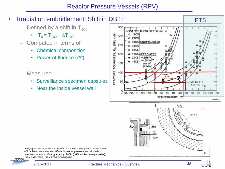
• Irradiation embrittlement: Shift in DBTT
– Defined by a shift in T100
• T0 = T100 + DT100
– Computed in terms of
• Chemical composition
• Power of fluence (Fn)
– Measured
• Surveillance specimen capsules
• Near the inside vessel wall
2016-2017 Fracture Mechanics - Overview 4848
Integrity of reactor pressure vessels in nuclear power plants : assessment
of irradiation embrittlement effects in reactor pressure vessel steels.
International Atomic Energy Agency, 2009. (IAEA nuclear energy series),
ISSN 1995-7807, ISBN 978-92-0-101709-3
PTS
DT100
Page 49
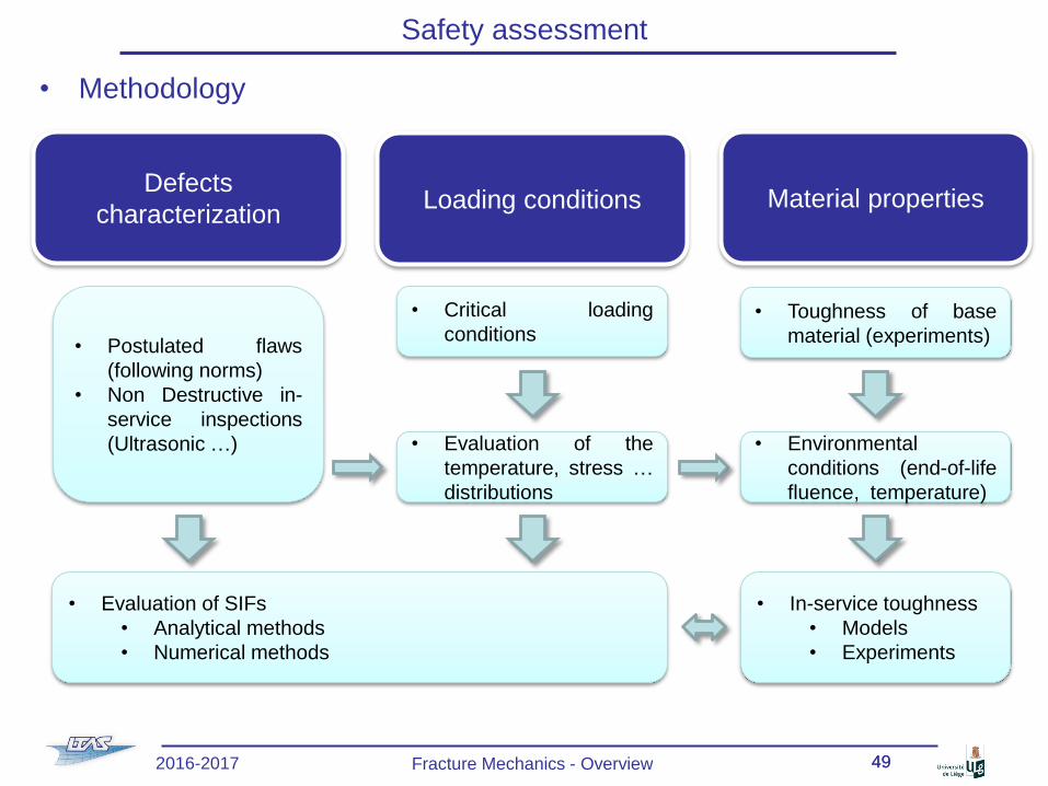
Safety assessment
• Methodology
2016-2017 Fracture Mechanics - Overview 4949
Defects
characterizationLoading conditions Material properties
• Postulated flaws
(following norms)
• Non Destructive in-
service inspections
(Ultrasonic …)
• Evaluation of SIFs
• Analytical methods
• Numerical methods
• Critical loading
conditions
• Evaluation of the
temperature, stress …
distributions
• Environmental
conditions (end-of-life
fluence, temperature)
• In-service toughness
• Models
• Experiments
• Toughness of base
material (experiments)
Page 50
Cyclic loading
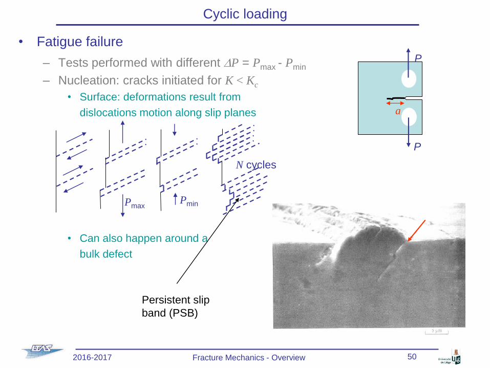
• Fatigue failure
– Tests performed with different DP = Pmax - Pmin
– Nucleation: cracks initiated for K < Kc
• Surface: deformations result from
dislocations motion along slip planes
• Can also happen around a
bulk defect
P
P
a
N cycles
PminPmax
Persistent slip
band (PSB)
2016-2017 Fracture Mechanics - Overview 50
Page 51
Cyclic loading
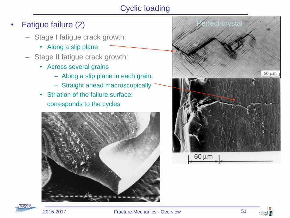
• Fatigue failure (2)
– Stage I fatigue crack growth:
• Along a slip plane
– Stage II fatigue crack growth:
• Across several grains
– Along a slip plane in each grain,
– Straight ahead macroscopically
• Striation of the failure surface:
corresponds to the cycles
Perfect crystal
2016-2017 Fracture Mechanics - Overview 51
Page 52
Cyclic loading
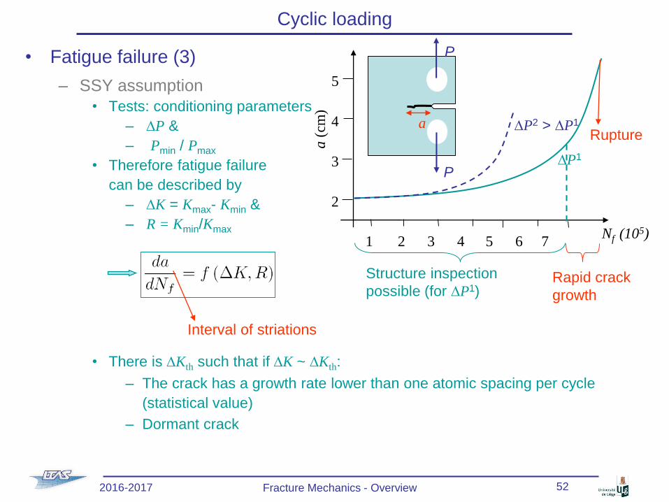
• Fatigue failure (3)
– SSY assumption
• Tests: conditioning parameters
– DP &
– Pmin / Pmax
• Therefore fatigue failure
can be described by
– DK = Kmax- Kmin &
– R = Kmin/Kmax
• There is DKth such that if DK ~ DKth:
– The crack has a growth rate lower than one atomic spacing per cycle
(statistical value)
– Dormant crack
Interval of striations
P
P
a
a(c
m)
Nf (105)1 2 3 4 5 6 7
5
4
3
2
DP1
DP2 > DP1
Structure inspection
possible (for DP1)Rapid crack
growth
Rupture
2016-2017 Fracture Mechanics - Overview 52
Page 53
Cyclic loading
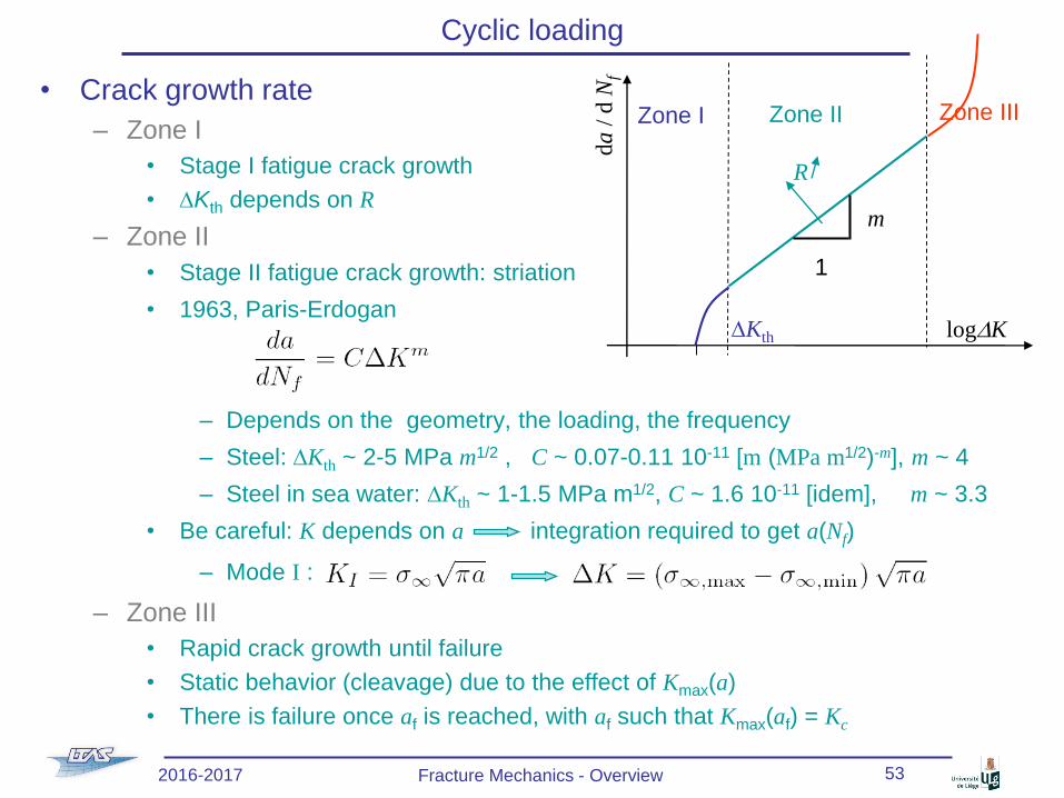
• Crack growth rate
– Zone I
• Stage I fatigue crack growth
• DKth depends on R
– Zone II
• Stage II fatigue crack growth: striation
• 1963, Paris-Erdogan
– Depends on the geometry, the loading, the frequency
– Steel: DKth ~ 2-5 MPa m1/2 , C ~ 0.07-0.11 10-11 [m (MPa m1/2)-m], m ~ 4
– Steel in sea water: DKth ~ 1-1.5 MPa m1/2, C ~ 1.6 10-11 [idem], m ~ 3.3
• Be careful: K depends on a integration required to get a(Nf)
– Mode I :
– Zone III
• Rapid crack growth until failure
• Static behavior (cleavage) due to the effect of Kmax(a)
• There is failure once af is reached, with af such that Kmax(af) = Kc
da
/ d
Nf
logDKDKth
Zone I Zone II Zone III
R
1
m
2016-2017 Fracture Mechanics - Overview 53
Page 54
Fatigue design
• « Infinite life design »
– sa < se: « infinite » life
– Economically deficient
• « Safe life design »
– No crack before a determined number of cycles
• At the end of the expected life the component
is changed even if no failure has occurred
• Emphasis on prevention of crack initiation
• Approach theoretical in nature
– Assumes initial crack free structures
– Use of sa – Nf curves (stress life)
• Add factor of safety
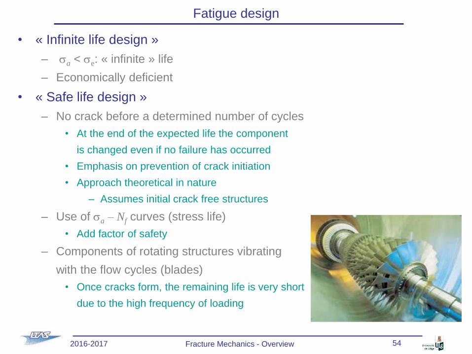
– Components of rotating structures vibrating
with the flow cycles (blades)
• Once cracks form, the remaining life is very short
due to the high frequency of loading
2016-2017 Fracture Mechanics - Overview 54
Page 55
Fatigue design
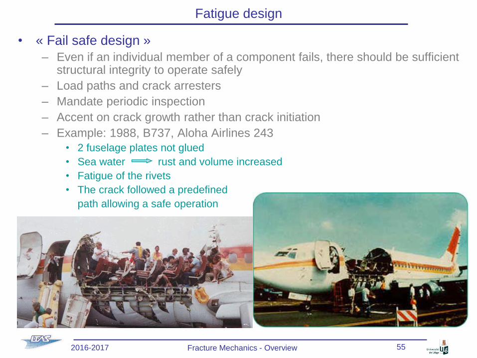
• « Fail safe design »
– Even if an individual member of a component fails, there should be sufficient structural integrity to operate safely
– Load paths and crack arresters
– Mandate periodic inspection
– Accent on crack growth rather than crack initiation
– Example: 1988, B737, Aloha Airlines 243
• 2 fuselage plates not glued
• Sea water rust and volume increased
• Fatigue of the rivets
• The crack followed a predefined
path allowing a safe operation
2016-2017 Fracture Mechanics - Overview 55
Page 56
Fatigue design
• « Damage tolerant design »
– Assume cracks are present from the beginning of service
– Characterize the significance of fatigue cracks on structural performance
• Control initial crack sizes through
manufacturing processes and
(non-destructive) inspections
• Estimate crack growth rates during
service (Paris-Erdogan) & plan
conservative inspection intervals
(e.g. every so many years, number
of flights)
• Verify crack growth during
these inspections
• Predict end of life (af)
• Remove old structures from service
before predicted end-of-life (fracture) or
implement repair-rehabilitation strategy
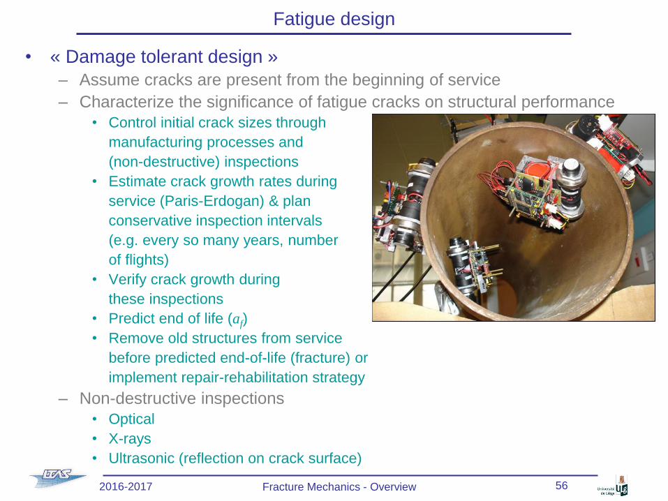
– Non-destructive inspections
• Optical
• X-rays
• Ultrasonic (reflection on crack surface)
2016-2017 Fracture Mechanics - Overview 56
Page 57
References
• Lecture notes
– Lecture Notes on Fracture Mechanics, Alan T. Zehnder, Cornell University,
Ithaca, http://hdl.handle.net/1813/3075
– Fracture Mechanics Online Class, L. Noels, ULg, http://www.ltas-
cm3.ulg.ac.be/FractureMechanics
– Fracture Mechanics, Piet Schreurs, TUe,
http://www.mate.tue.nl/~piet/edu/frm/sht/bmsht.html
• Book
– Fracture Mechanics: Fundamentals and applications, D. T. Anderson. CRC
press, 1991.
• RPV
– Documents
• Integrity of reactor pressure vessels in nuclear power plants : assessment of
irradiation embrittlement effects in reactor pressure vessel steels. International
Atomic Energy Agency, 2009. (IAEA nuclear energy series), ISSN 1995-7807,
ISBN 978-92-0-101709-3
• Pressurized thermal shock in nuclear power plants: good practices for
assessment, International Atomic Energy Agency, 2010 (iaea-tecdoc-1627), ISSN
1011-4289, ISBN 978-92-0-111109-8
2016-2017 Fracture Mechanics - Overview 57