ORIGINAL ARTICLE Frame element including effects of reinforcement slippage for nonlinear analysis of R/C structures Suchart Limkatanyu 1 and Agarat Samakrattakit 2 Abstract Limkatanyu, S. and Samakrattakit, A. Frame element including effects of reinforcement slippage for nonlinear analysis of R/C structures Songklanakarin J. Sci. Technol., 2003, 25(2) : 213-226 This paper presents the formulation and application of the flexibility-based, reinforced concrete frame model with bond-slip. The formulation starts from the derivation of the governing differential equa- tions (strong form) of the problem and then the flexibility-based, reinforced concrete frame model with bond-slip (weak form) is constructed to obtain the numerical solution of the problem. This numerical model is derived based on the principle of stationary complementary potential energy. Tonti’s diagrams are em- ployed to conveniently represent the governing equations for both strong and weak forms of the problem. This numerical model can be applied to both monotonic and cyclic loadings. The reinforced concrete column experimentally tested under cyclic loads is used to illustrate the model accuracy and to show the importance of bond-slip inclusion. Key words : finite elements, bond-slip model, nonlinear analysis, flexibility-based formulation 1 Ph.D. (Structural Engineering), 2 M.Eng. (Structural Engineering), Department of Civil Engineering, Faculty of Engineering, Prince of Songkla University, Hat Yai, Songkhla 90112 Thailand. Corresponding e-mail : [email protected]Received, 12 November 2002 Accepted, 22 January 2003
Transcript
ORIGINAL ARTICLE
Frame element including effects of reinforcement
slippage for nonlinear analysis of R/C structures
Suchart Limkatanyu1
and Agarat Samakrattakit2
AbstractLimkatanyu, S. and Samakrattakit, A.
Frame element including effects of reinforcement slippage for
nonlinear analysis of R/C structuresSongklanakarin J. Sci. Technol., 2003, 25(2) : 213-226
This paper presents the formulation and application of the flexibility-based, reinforced concrete
frame model with bond-slip. The formulation starts from the derivation of the governing differential equa-
tions (strong form) of the problem and then the flexibility-based, reinforced concrete frame model with
bond-slip (weak form) is constructed to obtain the numerical solution of the problem. This numerical model
is derived based on the principle of stationary complementary potential energy. Tonti’s diagrams are em-
ployed to conveniently represent the governing equations for both strong and weak forms of the problem.
This numerical model can be applied to both monotonic and cyclic loadings. The reinforced concrete column
experimentally tested under cyclic loads is used to illustrate the model accuracy and to show the importance
The accurate representation of the bond-slip effects is important in predicting the responseof reinforced concrete (R/C) frames under bothmonotonic and cyclic loads. Under the assump-tion of full composite action between the concreteand the reinforcing bars, the stiffness and strengthof R/C structures are overestimated, as is theenergy dissipated during the loading cycles. Anumber of experimental tests on R/C subassem-blages have shown the reduction in stiffness dueto slip in the reinforcing bars above the founda-tions and in the beam-column connections. Barpullout, which may be experienced in older struc-tures with insufficient bar anchorages or barsplices, drastically reduces the strength of the R/Cmembers. In order to realistically describe thebehavior of R/C structures in static and dynamicnonlinear structural analysis, the inclusion of thebond-slip effects is essential.
In recent years, major advances in model-ing the monotonic and cyclic response of R/Cframe structures have been accomplished. Espe-cially, frame models relying on the fiber-sectionmodels have found widespread uses in researchand professional practices. Fiber models are used
to compute the section interaction diagrams, beamdeflections, nonlinear static and dynamic frameresponses, etc. The main advantage of the fibermodel is that it automatically couples the interac-tion between axial and bending effects. Existingfiber-section models, however, are normally basedon the assumption that plane sections remainplane and that there is strain-compatibility bet-ween the concrete and the steel rebars, henceneglecting the bond-slip effects. This leads to anoverprediction of the initial stiffness and of thehysteretic energy dissipation of the R/C members(Spacone et al., 1996). The simplest way to ac-count for the bond-slip effects in frame elementsis to add nonlinear rotational springs at the ele-ment ends (Rubiano-Benavides, 1998). Althoughsimple, this way needs the formulation of anad-hoc phenomenological moment-rotation law,and disrupts the continuity of the fibers betweenadjacent elements.
The R/C frame elements with bond-slipproposed in this work are different from thosepublished to date in that different degrees of free-dom are used for the concrete beam and for thebars with bond-slip. In other words, the bond-slip
215Songklanakarin J. Sci. Technol.
Vol. 25 No. 2 Mar.-Apr. 2003
Reinforced concrete frame
Limkatanyu, S. and Samakrattakit, A.
between the steel bar and the surrounding con-crete is computed directly as the difference in thesteel and concrete displacements at the bar level.Aprile et al. (2001) have already successfullytested the general idea with the simple, stiffness-based formulation. The resulting model is com-putationally robust, but not very accurate. There-fore, a large number of elements are needed togain sufficient accuracy, hence requiring highcomputational efforts. To date, several researchers(e.g. Zeris and Mahin, 1988) have investigatedthe use of assumed force fields for the develop-ment of nonlinear frame elements. This intereststems from two main observations: a) in somesimplified cases the internal force distributions inframe elements are known “exactly”. This is forexam-ple the case of the R/C beam element withperfect bond; b) in general, the force fields alongthe beam are smoother than the deformationfields, which may show large jumps in the inelas-tic regions, particularly where plastic hinges tendto form (i.e. in column bases, girder ends, beam-midspan, etc.). Consequently, the uses of force-shape functions in the flexibility-based formula-tion are an encouraging way to improve the ac-curacy of finite element models.
This paper presents the general theoreticalframework of the flexibility-based formulationof R/C frame element with bond-slip in the steelbars. The beam section force-deformation rela-tions are derived from the fiber section model.The derivation of the governing differential equa-tions (strong form) of the R/C frame element withbond interfaces is presented first. The flexibility-based element formulation (weak forms) is pre-sented next and establishes the core of this paper.The flexibility-based element is derived from theprinciple of stationary complementary potentialenergy functional. The Tonti’s diagrams are usedto concisely illustrate the governing equations ofboth the strong and the weak forms. The flexibil-ity-based element is implemented in a finite ele-ment analysis program, FEAP (Taylor, 1998) andthe experimental result of the laterally loadedR/C column is used to validate the element accu-racy and to show the effects of reinforcement
slippages.
Equations of R/C frame element with bond-slip
(strong from)
Equilibrium
The free body diagram of an infinitesimalsegment dx of R/C frame element with n barswith bond interfaces is shown in Figure 1. Onlybond stresses tangential to the bars are consi-dered in this formulation. The dowel effect in thebars is neglected. Based on the small-deformationassumption, all of the equilibrium conditionsare considered in the undeformed configuration.Axial equilibriums in the beam component and inthe bar i lead to the following equations:
dNB (x)dx
+ Dbi (x) == 0i=1
n
∑∑
dNi (x)dx
- Dbi (x) == 0 , i = 1, n (1)
where NB(x) and N
i(x) are the axial forces in the
beam and in the bar i, respectively. Dbi(x) is the
bond interface force per unit length between thebeam and bar i. Vertical equilibrium of the infi-nitesimal segment dx yields :
dVB (x)dx
- py (x) == 0 (2)
where VB(x) is the beam section shear force and
py(x) is the transverse distributed load. Finally,
moment equilibrium yields:
dMB (x)
dx- VB (x) −− yi Dbi (x) == 0
i=1
n
∑∑ (3)
where MB(x) is the beam section bending mo-
ment, yi is the distance of bar i from the element
reference axis (Figure 1). This work follows theEuler-Bernoulli beam theory, thus the shear defor-mations are neglected. The shear force V
B(x) is
removed by combining Eqs. (2) and (3) to obtain
d2
MB (x)
dx2 −− py (x) −− yi
dDbi (x)dxi-1
n
∑∑ == 0 (4)
Reinforced concrete frame
Limkatanyu, S. and Samakrattakit, A.
Songklanakarin J. Sci. Technol.
Vol. 25 No. 2 Mar.-Apr. 2003 216
Figure 1. R/C beam element with bond-slip: Beam and bar components
Eqs. (1) and (4) represent the governingequilibrium equations of the R/C frame elementwith bond slip. Eqs. (1) and (4) can be written inthe following matrix form:
∂Β
ΤDΒ (x) - ∂b
ΤDb (x) - p(x) = 0 (5)
where DB(x) {D(x) M D
==(x)}
Τ are the element sec-
tion forces, D(x) == {NB (x) MB (x)}Τ are the beam
section forces, D==
(x) == {N1 (x) LNn (x)}Τ are the bar
forces, Db(x) = {D
b1(x) LD
bn(x)}
T are the bond
section forces and p(x) = {0 py(x) 0 L 0}
T is
the element force vector. ∂Β and ∂b are differentialoperators defined in Appendix II. It is important
to point out that there are 2n + 2 internal forceunknowns while only n+2 equilibrium equa-tions are available at any element section. Conse-quently, this system is internally statically inde-terminate and the internal forces cannot be deter-mined solely by the equilibrium conditions.
Compatibility
The element section deformation vector
conjugate of DB(x) is d
B(x) = {d(x) M d
=
(x)}T
, where
d(x) == {εB (x) κ
B(x)}
T are the beam section defor-
mations (axial strain εB at reference axis and cur-
vature κB) , and d
=
(x) == {ε1 (x) L ε n (x)}T
containsthe axial strains of the n bars. The followingdisplacements are defined at the element level:
u(x) == {u(x) M u=
(x)}T
are the displacement fields
217Songklanakarin J. Sci. Technol.
Vol. 25 No. 2 Mar.-Apr. 2003
Reinforced concrete frame
Limkatanyu, S. and Samakrattakit, A.
along the element, where u(x) == {uB (x) vB (x)}T
contains the beam axial and transverse displace-
ments, respectively, and u=
(x) == {ui (x) L un (x)}T
contains the axial dis-placements of the n bars.From the small deformation assumption, the
element deformations are related to the elementdisplacements through the following compatibi-lity relations: ε
B(x) = du
B (x)/dx, κ
B(x) = d
2v
B(x)/
dx2, and ε
i(x) = du
i(x)/dx , which can be written
in the following matrix form:
d B (x) == ∂Bu(x) (6)
The bond slips are determined by the fol-lowing compatibility relation between the beamand the bar displacements:
ubi (x) == ui (x) −− uB (x) + yi
dvB (x)
dx (7)
where ubi(x) is the bond slip between the beam
and bar i . If the bond deformation vector db(x) =
{ub1
(x) L ubn
(x)}T is introduced, Eq. (7) can be
written in the following matrix form:
db(x) = ∂bu(x) (8)
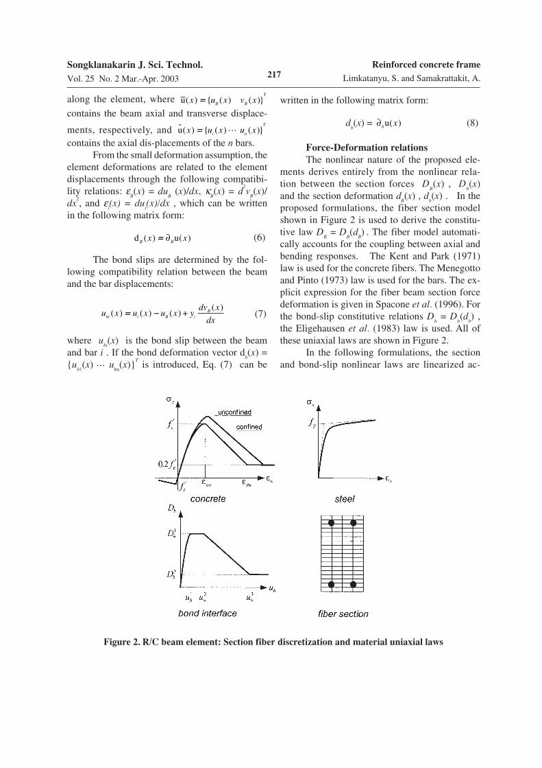
Force-Deformation relations
The nonlinear nature of the proposed ele-ments derives entirely from the nonlinear rela-tion between the section forces D
B(x) , D
b(x)
and the section deformation dB(x) , d
b(x) . In the
proposed formulations, the fiber section modelshown in Figure 2 is used to derive the constitu-tive law D
B = D
B(d
B) . The fiber model automati-
cally accounts for the coupling between axial andbending responses. The Kent and Park (1971)law is used for the concrete fibers. The Menegottoand Pinto (1973) law is used for the bars. The ex-plicit expression for the fiber beam section forcedeformation is given in Spacone et al. (1996). Forthe bond-slip constitutive relations D
b = D
b(d
b) ,
the Eligehausen et al. (1983) law is used. All ofthese uniaxial laws are shown in Figure 2.
In the following formulations, the sectionand bond-slip nonlinear laws are linearized ac-
Figure 2. R/C beam element: Section fiber discretization and material uniaxial laws
Reinforced concrete frame
Limkatanyu, S. and Samakrattakit, A.
Songklanakarin J. Sci. Technol.
Vol. 25 No. 2 Mar.-Apr. 2003 218
cording to the following forms:
DB (x) == DB
0
(x) + ∆DB (x) == DB
0
(x) + k B
0
(x)∆d B (x)
Db (x) == Db
0
(x) + ∆Db (x) == Db
0
(x) + k b
0
(x)∆d b (x) (9)
where DB
0
(x), Db
0
(x), k B
0
(x) and k b
0
(x) are the sec-tion and bond force vectors and stiffness matricesat the initial point. The consistent inverse of (9)can be expressed in the following forms:
dB (x) == d B
0
(x) + ∆d B (x) == d B
0
(x) + f B
0
(x)∆DB (x)
db (x) == d b
0
(x) + ∆d b (x) == d b
0
(x) + f b
0
(x)∆Db (x) (10)
where d B
0
(x), d b
0
(x), f B
0
(x) and f b
0
(x) are the sec-tion and bond deformation vectors and flexibilitymatrices at the initial point. In the above equationsand throughout the paper, superscript 0 indicatesthe value of a vector or matrix at the initial pointof the nonlinear scheme.
The compatibility, equilibrium and consti-tutive equations for the R/C frame element withbond-slip presented above are conveniently repre-sented in the classical Tonti’s diagram of Figure3. This diagram is going to be modified for thedifferent element formulations. Finally, for sim-plicity, the transverse load p
y(x) is omitted in the
following derivations.
Flexibility-based (force-hybrid) formulation
(weak form)
The flexibility-based formulation stemsfrom the flexibility-based steel-concrete compo-site beam element with partial interaction pro-posed by Salari et al. (1998). The flexibility-basedformulation is derived from the total comple-mentary potential energy functional and is thedual of the stiffness-based formulation. The ele-ment internal force fields D
B(x) and D
b(x) serve
as the primary unknowns and are expressed interms of the element nodal forces through appro-priate force shape functions. The force shapefunctions are derived such that the equilibriumequations (5) are satisfied point-wise along theelement. On the other hand, the beam compatibil-ity equation (6) and the bond compatibility equa-tion (8) are satisfied only in an integral sense.The steps involved in the flexibility-based formu-lation are schematically represented in the Tonti'sdiagram of Figure 4.
The total complementary potential energyfunctional ∏
CPE is :
ΠCPE [DB (x), Db (x)] =
DB
T
(x)(d B (x) - ∂Bu(x))dx +L∫∫
Db
T
L∫∫ (x)(d b (x) - ∂bu(x))dx (11)
According to the principle of stationarycomplementary potential energy, the compatibleconfiguration is obtained when
CPE reaches a
Figure 3. Tonti’s diagram for R/C beam with bond-slip: Differential equations (strong form)
219Songklanakarin J. Sci. Technol.
Vol. 25 No. 2 Mar.-Apr. 2003
Reinforced concrete frame
Limkatanyu, S. and Samakrattakit, A.
Figure 4. Tonti’s diagram for R/C beam with bond-slip: Flexibility-based formulation
stationary value, i.e. when
δΠCPE [δDB (x), δDb (x)] = δDB
T
(x)(d B (x) - ∂Bu(x))dx +L∫∫ δDb
T
L∫∫ (x)(d b (x) - ∂bu(x))dx = 0 (12)
Upon substitution of the section linearized laws (10) , (12) is written
δΠCPE δDB
T
(x)(d B
0
(x) + f B
0
(x)∆DB (x)L∫∫ −− ∂Bu(x))dx + δDb
T
(x)(d b
0
(x) + f b
0
(x)∆Db (x)L∫∫ −− ∂bu(x))dx = 0 (13)
where δDB(x) and δD
b(x) are virtual, equilibrated section and bond-interface force fields, respec-
tively, and f B
0
(x) and f b
0
(x) are the initial flexibi-lity matrices of the section and of the bond-interfaces,respectively. Integration by parts of (13) and substitution of the equilibrium equation (5)lead to the following matrix equation:
δDB
δDb
L
∫∫(x)(x)
T
f B
0
(x) 0
0
f b
0
(x)
∆DB
∆Db
(x) (x)
dx == δQT
U −−δDB
δDb
L
∫∫(x)(x)
T
d B
0
d b
0
(x)
(x)
dx (14)
where δQT
U is the boundary term and represents the external virtual work done by δQ (the virtual
element nodal forces without rigid body modes) on U (the corresponding element nodal displacementswithout rigid body modes). The element is formulated without rigid body modes in view ofits implementation in a general-purpose finite element code, which requires inversion of theelement flexibility matrix (Spacone et al. 1996). Eq. (14) is the backbone equation of the flexibility-based finite element formulation. To obtain the discrete form of (14), the section forces D
B(x) and the
bond-interface forces Db(x) are expressed in terms of the element nodal forces without rigid body modes
Q and of the bond-interface forces Qb at selected reference points along the interface, according to the
following matrix relation:
DB
Db
(x)(x)
=N BB
F-B
(x)
NbB
F-B
(x)
N Bb
F-B
(x)
Nbb
F-B
(x)
Q
Qb
(15)
where the superscript F-B denotes the flexibility-based formulation, and N BB
F-B
(x), N Bb
F-B
(x), NbB
F-B
(x), Nbb
F-B
(x)
are the force shape functions. Substitution of (15) into (14) and from the arbitrariness of δQ and δQb ,the following matrix expression results:
Reinforced concrete frame
Limkatanyu, S. and Samakrattakit, A.
Songklanakarin J. Sci. Technol.
Vol. 25 No. 2 Mar.-Apr. 2003 220
FBB
0
FBb
0 T
FBb
0
Fbb
0
∆Q
∆Qb
==
U
0
−−
r0
r b
0
(16)
where FBB
0
, FBb
0 , Fbb
0 are the following flexibility
terms:
FBB
0
== N BB
F-B T
f B
0
N BB
F-B
+ NbB
F-B T
f b
0
NbB
F-B
dxL∫∫
FBb
0
== N BB
F-B T
f B
0
N Bb
F-B
+ NbB
F-B T
f b
0
Nbb
F-B
dxL∫∫
Fbb
0
== N Bb
F-B T
f B
0
N Bb
F-B
+ Nbb
F-B T
f b
0
Nbb
F-B
dxL∫∫
(17)
r0
and r b
0
represent the displacements at the elementand bond degrees of freedom, respectively, com-
patible with the internal deformations d B
0
and d b
0
:
r0
== N BB
F-B T
d B
0
+ NbB
F-B T
d b
0
dxL∫∫
r b
0
== N Bb
F-B T
d B
0
+ Nbb
F-B T
d b
0
dxL∫∫
(18)
In fact, U - r0and - r b
0
represent the element
nodal and bond displacement residuals, respec-tively, in the flexibility equation (16). The zeroterm on the right-hand side of (16) implies thatthe relative bond-slips at the selected referencepoints along the interfaces are equal to zero. Thiscondition is similar to the known displacementconditions that are used to determine the redun-dant forces in statically indeterminate structuresby the classical force method.
The redundant force unknowns ∆Qb are
eliminated through static condensation in (16).The second equation in (16) yields ∆Qb ==
−−(Fbb
0
)-1
(FbB
0
∆Q + r b
0
) , which substituted in the first
equation yields
F0
∆Q = U −− UB
0
−− Ub
0 (19)
where F is element flexibility matrix defined as:
F0
= FBB
0
−− FBb
0
(Fbb
0
)-1
FbB
0 (20)
and UB
0
, Ub
0
are the contributions of the beam com-ponent and of the bond-interfaces, respectively,to the element nodal displacements U
0
withoutrigid body modes:
UB
0
== N BB
F-B T
−− FBb
0
(Fbb
0
)-1
N Bb
F-B T
d B
0
dxL∫∫
Ub
0
== NbB
F-B T
−− FBb
0
(Fbb
0
)-1
Nbb
F-B T
d b
0
dxL∫∫
(21)
The right-hand side vector U - UB
0
- Ub
0 of
(19) represents the element nodal displacementresiduals corresponding to the weak form of thecompatibility conditions (6) , (8) and vanisheswhen the compatible configuration is reached.
Figure 5 shows the 2-node flexibility-basedR/C frame element with and without rigid bodymodes. Adding the rigid body modes to the ele-ment of Figure 5b or filtering-out the rigid bodymodes from the element of Figure 5a is accom-plished through matrix transformations based onequilibrium and compatibility between the twosystems.
In structures that are internally staticallydeterminate, such as the R/C beam with perfectbond of Spacone et al. (1996), the internal forcedistributions can be determined exactly fromequilibrium. It is also important to remark that inthis case only beam deformation contributes tothe total complementary potential energy func-tional ∏
CPE . In the R/C beam model with bond-
slip of Figure 5, which is internally staticallyindeterminate, the internal force distributions can-not be exactly determined from equilibrium only,except for some special, simple linear-elasticstructures. The bond-interface forces serve as theredundant forces in this element. Assumptions onthe bond force distributions are made. This proce-dure is identical to that followed by Salari et al.(1998) for the steel-concrete composite beam withdeformable shear connectors. In the proposedformulation of a R/C element with bond-slip, thebond-force distributions are assumed to be cubicfunctions. During the element development, aquadratic bond-interface force distribution was
221Songklanakarin J. Sci. Technol.
Vol. 25 No. 2 Mar.-Apr. 2003
Reinforced concrete frame
Limkatanyu, S. and Samakrattakit, A.
Figure 5. 2-Node flexibility-based R/C element with bond-slip
also tested, but it was discarded because it did notaccurately represent the actual bond distribution.The beam axial force and bending moment andthe bar axial force distributions corresponding tothe cubic bond-interface force distributions arequartic functions.
Low-Moehle Specimen 1 (Low and Moehle,
1987)
A series of R/C cantilever columns withrectangular cross section were tested by Low andMoehle (1987). A constant axial force represent-ing the gravity load and cyclic lateral displace-ments representing seismic actions were appliedto the columns. One of these columns, referred asLow-Moehle Specimen 1, was modeled by Spaconeet al. (1996) to validate the flexibility-based for-mulation of a R/C frame element with perfectbond. Though the correlation study between ex-perimental and numerical results was rather satis-factory in aspects of strength, the experimentalresult was more flexible than the numerical solu-
tion. This is due to the fact that the model withperfect bond could not represent the base rota-tions resulting from the large slips of the reinforc-ing bars in the anchorage zone. The same speci-men is used herein to verify the proposed modelaccuracy and to show the effects of reinforcementslippages.
Figure 6 shows the specimen geometry.The column was subjected to a constant axial
compression of 44.5 kN (approximately 5% f c
'
Ag )and a cyclic lateral displacement causing flexureabout the weak axis. According to the report byLow and Moehle (1987) and using the labeling ofFigure 6, the material properties are: f
y 447.5 MPa
for rebar set I, fy 444 MPa for rebar set II and
fy
504 MPa for rebar set III. The ultimate com-pressive strengths of unconfined and confinedconcrete are 36.54 MPa and 42.13 MPa, respec-tively. The tensile strength of concrete, thoughconsidered in the analyses, does not affect theresults, except at the very early loading stages,before the base section cracks. As for the bond
Reinforced concrete frame
Limkatanyu, S. and Samakrattakit, A.
Songklanakarin J. Sci. Technol.
Vol. 25 No. 2 Mar.-Apr. 2003 222
Figure 6. Geometry and loads of Low-Moehle Specimen 1
stress-slip relation, in the test bond did not fail orreach the plateau shown in Figure 2, thus only theascending branch of the bond-slip envelope is ofinterest. The simple linear model is used withstiffness of 8.75 MPa/mm for bar set I (bars #3)and 9.05 MPa/mm for bar set II and III (bars #2).These values are based on a set of formulasdeveloped by Monti et al. (1994) from the regres-sion analysis on a number of pullout tests avail-able in the published literature. In the numericalmodel, the column is discretized into 1 element,plus 1 element representing the anchorage zone.In the original test specimen, the rebars werehooked 7 in. (177.8 mm) into the foundation. Tosimulate the effect of the hooks, the bar nodes areassumed fully anchored 7 in. into the foundation(Figure 6).
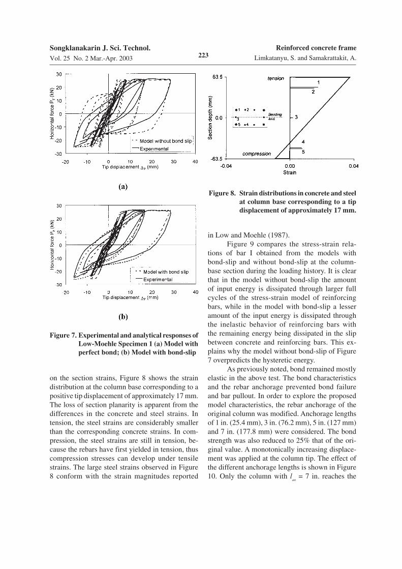
Figure 7a compares the tip force-displace-ment response from the experimental test withthe numerical result obtained with the flexibility-based R/C frame element with perfect bond(Spacone et al., 1996), while Figure 7b superim-poses the tip force-displacement response fromthe experimental test with the numerical resultobtained with the flexibility-based R/C frame ele-
ment with bond-interfaces proposed in this study.As expected, both models predict the same columnstrength. Bond-slip mostly affects the columnstiffness and the shape of the unloading-reloadingcurves. The model without bond-slip over-predictsthe hysteretic energy of the specimen. During un-loading, initial unloading is followed by closing ofthe crack, reloading and yielding of the steel intension. With the model with bond-slip, when thecolumn unloads, closing of the crack is accompa-nied by slip of the rebars at the column base. Thisgives a more flexible response, and yielding ofthe rebars in tension is delayed. It should be notedthat the initial unloading stiffness predicted bythe proposed model is somehow more flexiblethan the experimental one. This is mostly due tothe selection of a linear unloading branch for thebond law. A more refined curve would yield asmoother trend, but the overall response of themodel would be unaffected. The specimen initialstiffness is also smaller for the model with bond-slip, since some slip is present from the initialphases of loading, as shown in a number of testson R/C columns and frames.
In order to show the effects of bond-slip
223Songklanakarin J. Sci. Technol.
Vol. 25 No. 2 Mar.-Apr. 2003
Reinforced concrete frame
Limkatanyu, S. and Samakrattakit, A.
Figure 7. Experimental and analytical responses of
Low-Moehle Specimen 1 (a) Model with
perfect bond; (b) Model with bond-slip
on the section strains, Figure 8 shows the straindistribution at the column base corresponding to apositive tip displacement of approximately 17 mm.The loss of section planarity is apparent from thedifferences in the concrete and steel strains. Intension, the steel strains are considerably smallerthan the corresponding concrete strains. In com-pression, the steel strains are still in tension, be-cause the rebars have first yielded in tension, thuscompression stresses can develop under tensilestrains. The large steel strains observed in Figure8 conform with the strain magnitudes reported
Figure 8. Strain distributions in concrete and steel
at column base corresponding to a tip
displacement of approximately 17 mm.
in Low and Moehle (1987).Figure 9 compares the stress-strain rela-
tions of bar I obtained from the models withbond-slip and without bond-slip at the column-base section during the loading history. It is clearthat in the model without bond-slip the amountof input energy is dissipated through larger fullcycles of the stress-strain model of reinforcingbars, while in the model with bond-slip a lesseramount of the input energy is dissipated throughthe inelastic behavior of reinforcing bars withthe remaining energy being dissipated in the slipbetween concrete and reinforcing bars. This ex-plains why the model without bond-slip of Figure7 overpredicts the hysteretic energy.
As previously noted, bond remained mostlyelastic in the above test. The bond characteristicsand the rebar anchorage prevented bond failureand bar pullout. In order to explore the proposedmodel characteristics, the rebar anchorage of theoriginal column was modified. Anchorage lengthsof 1 in. (25.4 mm), 3 in. (76.2 mm), 5 in. (127 mm)and 7 in. (177.8 mm) were considered. The bondstrength was also reduced to 25% that of the ori-ginal value. A monotonically increasing displace-ment was applied at the column tip. The effect ofthe different anchorage lengths is shown in Figure10. Only the column with l
an = 7 in. reaches the
Reinforced concrete frame
Limkatanyu, S. and Samakrattakit, A.
Songklanakarin J. Sci. Technol.
Vol. 25 No. 2 Mar.-Apr. 2003 224
Figure 9. Stress-strain loading history of bar I: (a) Model without bond-slip; (b) Model with bond-slip
strength of the original column of Figure 7. In thiscase bond fails at the column base but the rebarsin tension do not totally pull-out because the steelrebars yield before bond can fail throughout theanchorage length. On the other end, for shorteranchorage lengths the column fails because ofcomplete bar pull-out from the foundation block,while the steel rebars remain linear elastic.
Summary and Conclusions
This paper presents the derivation of thegoverning differential equations (strong form) and
derives the flexibility-based finite element for-mulation (weak forms) for the R/C frame elementwith bond-interfaces. The flexibility-based (forcehybrid) element is derived from the principle ofstationary total complementary potential energyfunctional and employs force-shape functions toexpress the internal force fields in terms of forcedegrees of freedom. In this element, the elementbond forces at selected reference points serve asinternal redundant forces, and are statically con-densed out in order to implement the element intoa general-propose stiffness-based finite elementprogram. As a result, the bond force continuity
225Songklanakarin J. Sci. Technol.
Vol. 25 No. 2 Mar.-Apr. 2003
Reinforced concrete frame
Limkatanyu, S. and Samakrattakit, A.
between adjacent elements is locally relaxed.Tonti’s diagrams are also used to schematicallyrepresent the set of basic governing equations forboth strong and weak forms.
The correlation study between experimentaland numerical results of a R/C column subjectedto cyclic loading is used to show the importanceof bond-slip in modeling the response of R/Cstructures and to validate the model formulation.The inclusion of bond-slip effects results in a pre-
diction of the experimental results that is muchmore accurate than that obtained with a fibermodel without bond-slip. The model can also tracefailure of the column by bar pull-out. Pull-outtests can be extended to different bar materials,such as mild steel, prestressing steel and FRPbars. Pull-out studies can be performed to study ofthe effects of bond and anchorage lengths for en-hancing design provisions.
Figure 10. Column response with weak bond and reduced anchorage length
Notation
∂B ==
ddx
0 M 0 0 0
0 d
2
dx2 M 0 0 0
L L L L L L
0 0 M ddx
L 0
0 0 M 0 L 0
0 0 M 0 L ddx
== beam differential operator ;
∂b ==
−−1 y1
ddx
1 0 0
L L L L L
−−1 yn
ddx
0 0 1
== bond differential operator.
Reinforced concrete frame
Limkatanyu, S. and Samakrattakit, A.
Songklanakarin J. Sci. Technol.
Vol. 25 No. 2 Mar.-Apr. 2003 226
References
Aprile, A., Spacone, E., and Limkatanyu, S. 2001. Roleof bond in beams strengthened with steel andFRP plates, ASCE J. of Structural Engineering,127(12) : 1445-1452.
Eligehausen, R., Popov, E.P., and Bertero, V.V. 1983.Local bond stress-slip relationships of deformedbars under generalized excitations: experi-mental results and analytical model. EERCReport 83-23, Earthquake Engineering ResearchCenter, University of California, Berkeley.
Kent, D.C. and Park, R. 1971. Flexural members withconfined Concrete. ASCE Journal of the Struc-tural Division, 97(7) : 1964-1990.
Low, S.S., and Moehle, J.P. 1987. Experimental Studyof Reinforced Concrete Columns Subjected toMulti-Axial Cyclic Loading. EERC Report 87/14, Earthquake Engineering Research Center,University of California, Berkeley.
Menegotto, M., and Pinto, P.E. 1973. Method of analy-sis for cyclically loaded reinforced concreteplane frames including changes in geometryand nonelastic behavior of elements undercombined normal force and bending. IABSESymposium on Resistance and Ultimate De-formability of Structures Acted on by Well-Defined Repeated Loads, Lisbon, Portugal:112-123.
Monti, G., De Sortis, A., and Nuti, C. 1994. Problemidi scala nella sperimentazione pseudodinamicadi pile da ponte in C.A. (in Italian). Proceedings,Workshop Danneggiamento, Prove Cicliche ePseudodinamica, (Damage, Cyclic Tests andPseudo-dynamic Testing), Napoli, Italy.
Rubiano-Benavides, N.R. 1998. Predictions of theinelastic seismic response of concrete struc-tures including shear deformations and an-chorage slip (Ph.D. dissertation), Department ofCivil Engineering, University of Texas, Austin.
Salari, M.R., Spacone, E., Shing P.B, D.M. Frangopol.1998. Nonlinear analysis of composite beamswith deformable shear connectors, ASCE J. ofStructural Engineering, 124(10) : 1148-1158.
Spacone, E., Filippou, F.C., and Taucer, F.F. 1996.Fibre beam-column model for nonlinear analy-sis of R/C frames. Part I: formulation, EarthquakeEngineering and Structural Dynamics, 25: 711-725.
Taylor, R.L. 1998. FEAP: A Finite Element AnalysisProgram. User manual: Version 7.1, Departmentof Civil and Environmental Engineering, Uni-versity of California, Berkeley.
Zeris, C.A. and Mahin, S.A. 1988. Analysis of rein-forced concrete beam-columns under uniaxialexcitation, ASCE J. of Structural Engineering,114(4) : 804-820.