7" WIDE LCD MONITORAFFICHEUR À CRISTAUX LIQUIDES (LCD) COULEUR LARGE DE 7"PANEL LCD A COLOR PANTALLA ANCHA DE 7"
VMA8582Owner's manual & Installation manualMode d'emploi et manuel d'installationManual del usuario y de instlactión
Thank you for purchasing the Clarion VMA8582.Nous vous remercions d’avoir acheté le Clarion VMA8582.Muchas gracias por la adquisición del VMA8582 Clarion.
Esp
año
lF
rançais
En
glish
* Antes de pasar a la conexión de los cables y ala instalación, lea detenidamente este manualdel usuario y de instalación.
* Después de haber leído este manual, guárdeloa mano (p. ej., en la guantera).
Cuando venda su automóvil, deje en él elmanual de instrucciones a fin de que puedautilizarlo el nuevo usuario.
* Lea el contenido de la tarjeta de garantíaadjunta, y guárdela con este manual.
* Please read this Owner’s manual & Installa-tion manual in its entirety before proceedingwith wire connection and installation.
* After reading this manual, be sure to keep it ina handy place (e.g., glove compartment).
If you sell the motor vehicle, please leave themanual in it so that the new owner can use it.
* Read the contents of the enclosed warrantycard and keep it with this manual.
* Veuillez lire entièrement le mode d’emploi etle manuel d’installation avant de procéder auxconnexions et à l’installation.
* Après avoir lu ce mode d’emploi, prenez soinde le conserver dans un endroit pratique (parex: la boîte à gants).
Si vous vendez votre véhicule à moteur,laissez-y le manuel de façon que le nouveaupropriétaire puisse l’utiliser.
* Lisez le contenu de la carte de garantie com-prise et conservez-la avec ce manuel.
2 VMA8582 (U)
English
Français
Español
■ Table des matières1. PRÉCAUTIONS 332. CARACTÉRISTIQUES 343. PRÉCAUTIONS DE MANIPULATION 35
Nettoyage 354. NOMENCLATURE DES TOUCHES ET LEURS
FONCTIONS 36Module d'affichage 36Boîtier de commande 39
5. FONCTIONNEMENT 40Réglage du volume 40Sélection du mode d'écran (taille) 41Gradateur 42Réglage de l'image 45Système de diffusion télévisée: Rubrique PAL/NTSC 48
6. RACCORDEMENT D'UN APPAREILEXTERNE 49Exemple de raccordement 49
7. GUIDE DE DÉPANNAGE 528. SPECIFICATIONS 539. CERTIFICAT DE GARANTIE ET SERVICE
APRÉS-VENTE 54• Manuel d'installation/connexion 55
Français
■ Índice1. PRECAUCIONES 632. CARACTERÍSTICAS 643. PRECAUCIONES DE MANEJO 65
Limpieza 654. NOMBRES DE PARTES Y SUS FUNCIONES 66
Unidad de visualización 66Caja de control 69
5. OPERACIÓN 70Ajuste del volumen 70Selección del modo de pantalla (tamaño) 71Regulador de brillo 72Ajuste de la imagen 75Sistema de teledifusión: Ajuste de PAL/NTSC 78
6. CONEXIÓN DE EQUIPOS EXTERNOS 79Ejemplo de conexión 79
7. SOLUCIÓN DE PROBLEMAS 828. ESPECIFICACIONES 839. CERTIFICADO DE GARANTÍA Y SERVICIO
POSVENTA 84• Manual de instalación/Conexión de cables 85
Español■ Contents1. PRECAUTIONS 32. FEATURES 43. CAUTIONS ON HANDLING 5
Cleaning 54. NAMES OF THE PARTS AND THEIR FUNC-
TIONS 6Display unit 6Control Box 9
5. OPERATION 10Adjusting the Volume 10Selecting the Screen Mode (size) 11Dimmer 12Picture Adjustment 15Television Broadcast System: PAL/NTSC Setting 18
6. CONNECTION OF EXTERNAL EQUIPMENT 19Connection Example 19
7. TROUBLESHOOTING 228. SPECIFICATIONS 239. WARRANTY CERTIFICATE AND AFTER-
SERVICE 24• Installation/Wire Connection Manual 25
English
En
glish
Ow
ner’s M
anu
alF
rançais
Mo
de d
’emp
loi
Esp
año
lM
anu
al de
instru
ccion
es
VMA8582(U) 3
En
glish
Ow
ner’s M
anu
al
1. PRECAUTIONS1. This set is for use in DC 12V, negative ground
vehicles. Be sure to consult your store of pur-chase or a Clarion-designated service outletbefore installing it on DC 24V cars.
2. Do not operate the set in ways other thandescribed in this guide. Doing so may dam-age it.
3. Safety first! For rear seat use only. Do notinstall on dashboard or anywhere else thatwould permit monitor to be viewed by thedriver. Monitor must not be located in themotor vehicle at any point forward of the backof the front seats. Monitor must never be usedin any manner that will distract driver or inter-fere with driver’s safe operation of the motorvehicle.
4. Be careful not to run down the car batterywhile using the set with the car stopped.
5. For safety, install the set in a position at whichit cannot be seen by the driver.
6. Do not disassemble or modify the set. Doingso may damage it.
7. Keep drinks and drops from umbrellas awayfrom the set. Water may damage the internalcircuitry.
8. Do not let lit cigarettes or other hot objectstouch the set. Doing so may damage or de-form the cabinet.
9. Do not let the set become hot. If the tempera-ture in the car is high or if the set has beenexposed to direct sunlight and is hot, lowerthe temperature before using it.(The LCD panel will work properly within atemperature range of 0 to 40 ˚C.)
10.In extremely cold temperatures, the movementof the picture may be slow and the picture maybe dark, but this is not a malfunction. The setwill work normally once the temperature in-creases.
11.Small black and shiny dots inside the liquidcrystal panel are normal for liquid crystal prod-ucts.
Clar ion Company.Limited. MADE IN JAPAN
NO USEVIDEO
L - A U D I O - R
AV
OU
TP
UT
L - A U D I O - RVIDEO
AV
IN
PU
T
1
2
VIDEO / CAMERA
This device complies with Part 15 of the FCC Rules. Operation is subject to the following two conditions : (1) This device may not cause harmful interference,and (2) This device must accept any interference received,
7WMPALA
MODEL NO. ZM-7000Assembled From Tested Components (Complete System Not Tested)FOR HOME OR CAR USE
Clar ion Company.Limited. MADE IN JAPAN
NO USEVIDEO
L - A U D I O - R
AV
OU
TP
UT
L - A U D I O - RVIDEO
AV
IN
PU
T
1
2
VIDEO / CAMERA
This device complies with Part 15 of the FCC Rules. Operation is subject to the following two conditions : (1) This device may not cause harmful interference,and (2) This device must accept any interference received, including interference that may cause undesired operation. 7WMPALA
MODEL NO. ZM-7000Assembled From Tested Components (Complete System Not Tested)FOR HOME OR CAR USE
This equipment has been tested and found to comply with the limits for a Class B digital device,pursuant to Part 15 of the FCC Rules. These limits are designed to provide reasonable protectionagainst harmful interference in a residential installation. This equipment generates, uses, andcan radiate radio frequency energy and, if not installed and used in accordance with the instruc-tions, may cause harmful interference to radio communications. However, there is no guaranteethat interference will not occur in a particular installation. If this equipment does cause harmfulinterference to radio or television reception, which can be determined by turning the equipmentoff and on, the user is encouraged to consult the dealer or an experienced radio/TV technicianfor help.
4 VMA8582 (U)
En
glish
Ow
ner’s M
anu
al
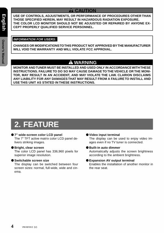
CAUTIONUSE OF CONTROLS, ADJUSTMENTS, OR PERFORMANCE OF PROCEDURES OTHER THANTHOSE SPECIFIED HEREIN, MAY RESULT IN HAZARDOUS RADIATION EXPOSURE.THE COLOR LCD MONITOR SHOULD NOT BE ADJUSTED OR REPAIRED BY ANYONE EX-CEPT PROPERLY QUALIFIED SERVICE PERSONNEL.
WARNINGMONITOR AND TUNER MUST BE INSTALLED AND USED ONLY IN ACCORDANCE WITH THESEINSTRUCTIONS. FAILURE TO DO SO MAY CAUSE DAMAGE TO THE VEHICLE OR THE MONI-TOR, MAY RESULT IN AN ACCIDENT, AND MAY VIOLATE THE LAW. CLARION DISCLAIMSANY LIABILITY FOR ANY DAMAGES THAT MAY RESULT FROM A FAILURE TO INSTALL ANDUSE THIS UNIT AS STATED IN THESE INSTRUCTIONS.
INFORMATION FOR USERS:
CHANGES OR MODIFICATIONS TO THIS PRODUCT NOT APPROVED BY THE MANUFACTURERWILL VOID THE WARRANTY AND WILL VIOLATE FCC APPROVAL.
2. FEATURE● 7" wide-screen color LCD panel
The 7" TFT active matrix color LCD panel de-livers striking images.
● Bright, clear screenThe color LCD panel has 336,960 pixels forsuperior image resolution.
● Switchable screen sizeThe display can be switched between fourscreen sizes: normal, full-wide, wide and cin-ema.
● Video input terminalThe display can be used to enjoy video im-ages even if no TV tuner is connected.
● Built-in auto dimmerAutomatically adjusts the screen brightnessaccording to the ambient brightness.
● Expansion AV output terminalEnables the installation of another monitor inthe rear seat.
VMA8582(U) 5
En
glish
Ow
ner’s M
anu
al
• Don’t allow any liquids on the set from drinks,umbrellas etc. Doing so may damage the in-ternal circuitry.
• Do not disassemble or modify the set in anyway. Doing so may result in damage.
• Do not let cigarettes burn the display. Doingso may damage or deform the cabinet.
• If a problem should occur, have the set in-spected at your store of purchase.
• Do not hold on the LCD panel when adjustingthe angle of the LCD panel. Doing so may dam-age it.
For a longer service life, be sure to read the following cautions.
Cleaning• Cleaning the cabinet
Use a soft, dry cloth and gently wipe off thedirt.For tough dirt, apply some neutral detergentdiluted in water to a soft cloth, wipe off the dirtgently, then wipe again with a dry cloth.
Do not use benzine, thinner, car cleaner, etc.,as these substances may damage the cabinetor cause the paint to peel. Also, leaving rub-ber of plastic products in contact with the cabi-net for long periods of time may cause stains.
• Cleaning the LCD panelThe LCD panel tends to collect dust, so wipeit off occasionally with a soft and dry cloth.
The surface is easily scratched, so do not rubit with hard objects.
3. CAUTION ON HANDLING
6 VMA8582 (U)
En
glish
Ow
ner’s M
anu
al
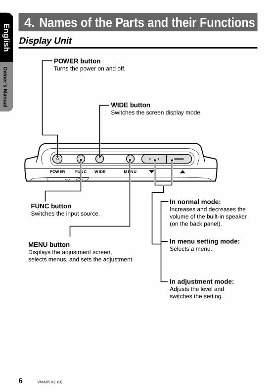
Display Unit
4. Names of the Parts and their Functions
POWER FUNC WIDE MENU
POWER button Turns the power on and off.
WIDE button Switches the screen display mode.
FUNC buttonSwitches the input source.
MENU buttonDisplays the adjustment screen, selects menus, and sets the adjustment.
In normal mode: Increases and decreases the volume of the built-in speaker (on the back panel).
In menu setting mode: Selects a menu.
In adjustment mode: Adjusts the level and switches the setting.
VMA8582(U) 7
En
glish
Ow
ner’s M
anu
al
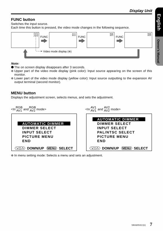
FUNC buttonSwitches the input source.Each time this button is pressed, the video mode changes in the following sequence.
❈ In menu setting mode: Selects a menu and sets an adjustment.
Note:● The on screen display disappears after 3 seconds.❈ Upper part of the video mode display (pink color): Input source appearing on the screen of this
monitor.❈ Lower part of the video mode display (yellow color): Input source outputting to the expansion AV
output terminal (second monitor).
MENU buttonDisplays the adjustment screen, selects menus, and sets the adjustment.
AV 1AV 1
AV 2AV 2
RGBAV 1
RGBAV 2
FUNC FUNC FUNC
Video mode display (❈ )
<In and mode>RGBAV1
RGBAV2 <In and mode>
AV1AV1
AV2AV2
8 VMA8582 (U)
En
glish
Ow
ner’s M
anu
al
Display Unit
Dimmer sensorWhen AUTOMATIC DIMMER is selected in dimmer setting, the brightness of the screen is adjusted automatically according to the ambient brightness.
STAND BY (R), ON(G)When the power is turned off..........red colorWhen the power is turned on..........green color
Receiver for remote control unit
Built-in speaker (on the back panel)
The screw hole is provided to install a TV stand at the bottom of this monitor. (1/4 inch unified screw thread, 4.5 mm of maximum length)
Terminal to which cables from the control box are connected. (on the right side of the monitor)
Precautions on handling of the LCD panel• Do not leave the monitor on the dashboard with the LCD panel facing upwards. (Range of storage
temperature: -20˚C to +80˚C)When the temperature is high or low, chemical changes occur in the LCD panel, resulting in damageto the monitor.
• Since the LCD panel has been specially processed, the fingerprints will remain on the panel andstand out if you touch the panel. Avoid touching the panel as much as possible. Also avoid pushingthe panel.
• When temperature becomes low, the picture does not appear or sometimes it takes time to appear.On occasion, the picture motion seems to be different from that at normal temperature and thepicture quality deteriorates. These phenomena are not a malfunction. (Range of operating tempera-ture: 0˚C to +40˚C)
• On the panel red dots, blue dots and green dots are found. This is peculiar to the LCD panel and it isnot a malfunction.[The LCD panel has been designed and manufactured using a highly developed precision technol-ogy and has a 99.99 % or more effective pixels. However, note that 0.01 % of pixels are defectiveand always light.]
CAUTION
VMA8582(U) 9
En
glish
Ow
ner’s M
anu
al
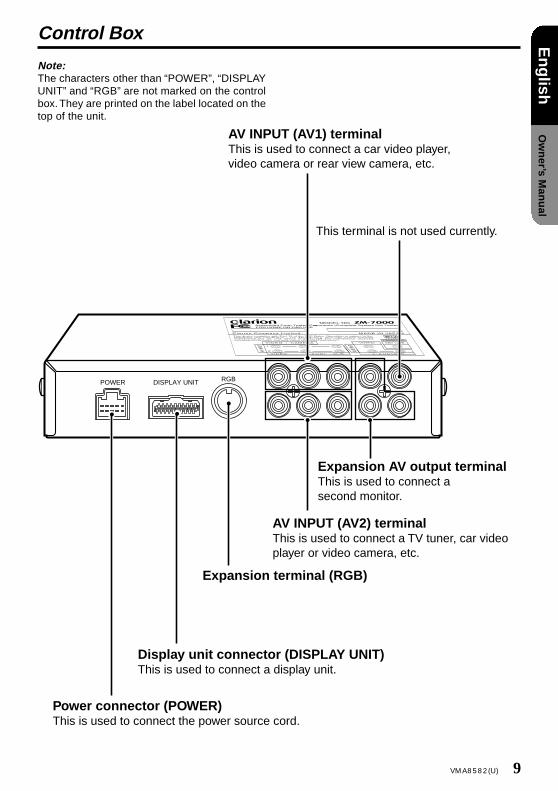
Control Box
Note:The characters other than “POWER”, “DISPLAYUNIT” and “RGB” are not marked on the controlbox. They are printed on the label located on thetop of the unit.
POWER DISPLAY UNIT RGB
Power connector (POWER)This is used to connect the power source cord.
AV INPUT (AV1) terminalThis is used to connect a car video player, video camera or rear view camera, etc.
This terminal is not used currently.
Expansion AV output terminalThis is used to connect a second monitor.
AV INPUT (AV2) terminalThis is used to connect a TV tuner, car video player or video camera, etc.
Expansion terminal (RGB)
Display unit connector (DISPLAY UNIT)This is used to connect a display unit.
10 VMA8582 (U)
En
glish
Ow
ner’s M
anu
al
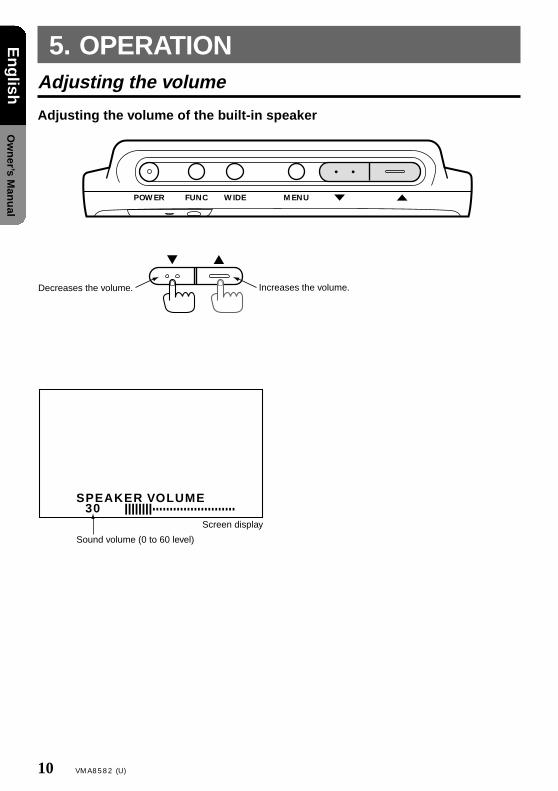
Adjusting the volume
Adjusting the volume of the built-in speaker
5. OPERATION
POWER FUNC WIDE MENU
Increases the volume.Decreases the volume.
30SPEAKER VOLUME
Sound volume (0 to 60 level)
Screen display
VMA8582(U) 11
En
glish
Ow
ner’s M
anu
al
Selection of the screen mode (size)
The following screen display modes are supported: normal, full wide, wide and cinema.
Notes:• Various screen display modes are available on
this monitor.If you select the screen display mode which isdifferent from the image ratio of software, suchas a TV program, it differs in appearance fromthe original image. Please keep this in mindand select the appropriate screen displaymode.
Selecting a screen display modePressing the WIDE button switches the screen display mode as follows: NORMAL→F•WIDE→WIDE-→CINEMA→NORMAL→❈ The screen display mode can be set for each video source.
F WIDE
WIDECINEMA
NORMAL
CINEMA
● Full wide mode
● Wide mode
● Normal mode
● Cinema mode
Picture of a normal TV program (4:3)
This mode enlarges a normal picture in all, and allows you to enjoy the picture in a larger size.However, the upper and lower parts of the picture, or the right and left parts of the picture will be missed.
This mode enlarges a picture only horizontally and fully to the screen edges in a balanced manner.
This mode enlarges a normal picture only horizontally and fully to the screen edges.(This enlarges the picture in a small area in the center, and in a large area in the proximity of the right and left side of the screen. This enlarges the picture in a natural manner with a lesser feeling of being out of harmony.)
• If you reduce or enlarge an image using thescreen display mode switching function (fullwide, cinema, etc.) of this monitor with profitin mind or for any purpose of making the pub-lic watch it or listen to it, it may infringe therights of the author who is protected under thecopyright law.
12 VMA8582 (U)
En
glish
Ow
ner’s M
anu
al
Dimmer
In case of auto modeThe factory default setting is auto mode.This mode adjusts the screen brightness automatically according to the ambient brightness.
1. Press the MENU button.Confirm that “AUTOMATIC DIMMER” is se-lected.
2. Press the MENU button again.The auto dimmer (dark level) display appears.
3. Adjust the screen brightness using the ▼ and▲ buttons so that you can see the screen withgreat ease at night time. (-60 to ±0)
Notes:• When the menu screen is displayed and “END”
is selected in step 1 or a further operation isnot performed for 10 seconds, the menu dis-play disappears automatically.
• If you adjust the screen brightness so that thescreen can be seen with great ease at night-time, the screen brightness will be adjustedautomatically from the maximum luminance tothe minimum luminance (the brightness atwhich the screen can be seen with great easeat nighttime).(It is recommended to set the AUTOMATICDIMMER level at -40 to -60.)
• If you set the AUTOMATIC DIMMER level to±0, the screen brightness level will be fixed tothe maximum luminance and the screen bright-ness will not change.
POWER FUNC WIDE MENU
–55AUTOMATIC DIMMER
–55AUTOMATIC DIMMER
If you set the AUTOMATIC DIMMER level to ± 0, the screen brightness does not change.
VMA8582(U) 13
En
glish
Ow
ner’s M
anu
al
Dimmer
POWER FUNC WIDE MENU
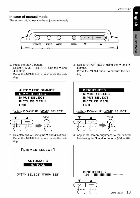
In case of manual modeThe screen brightness can be adjusted manually.
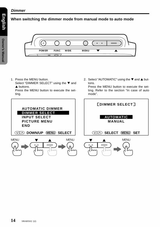
1. Press the MENU button.Select “DIMMER SELECT” using the ▼ and▲ buttons.Press the MENU button to execute the set-ting.
2. Select “MANUAL” using the ▼ and ▲ buttons.Press the MENU button to execute the set-ting.
3. Select “BRIGHTNESS” using the ▼ and ▼buttons.Press the MENU button to execute the set-ting.
4. Adjust the screen brightness to the desiredlevel using the ▼ and ▲ buttons. (-60 to ±0)
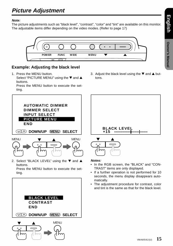
Note:The picture adjustments such as “black level”, “contrast”, “color” and “tint” are available on this monitor.The adjustable items differ depending on the video modes. (Refer to page 17)
Example: Adjusting the black level
1. Press the MENU button.Select “PICTURE MENU” using the ▼ and ▲buttons.Press the MENU button to execute the set-ting.
2. Select “BLACK LEVEL” using the ▼ and ▲buttons.Press the MENU button to execute the set-ting.
3. Adjust the black level using the ▼ and ▲ but-tons.
TRAST” items are only displayed.• If a further operation is not performed for 10
seconds, the menu display disappears auto-matically.
• The adjustment procedure for contrast, colorand tint is the same as that for the black level.
16 VMA8582 (U)
En
glish
Ow
ner’s M
anu
al
Picture Adjustment
Selecting picture adjustment itemsThe picture adjustments available on the monitor differ depending on each video mode. Press theFUNC button to select the video mode.
The “black level” and “contrast” adjustments arepossible.
DOWN/UP SELECTMENU
BLACK LEVELCONTRASTCOLORTINTEND
<In and mode>AV1AV1
AV2AV2
<NTSC mode>
DOWN/UP SELECTMENU
BLACK LEVELCONTRASTCOLOREND
<PAL mode>
<In and mode>AV1AV1
AV2AV2
DOWN/UP SELECTMENU
BLACK LEVELCONTRASTEND
<In and mode>RGBAV1
RGBAV2
The “black level”, “contrast” and “color” adjust-ments are possible.
The “black level”, “contrast”, “color” and “tint” ad-justments are possible.
Note:The selection between “PAL mode” and “NTSC mode” is performed by the “PAL/NTSC SELECT” set-ting. (Refer to page 18.)
VMA8582(U) 17
En
glish
Ow
ner’s M
anu
al
Picture Adjustment
Points of adjustment (The picture adjustment can be performed in each screen.)
–15BLACK LEVEL
+15BLACK LEVEL
This adjustment is performed to allow the dark portion of the screen to be seen with ease (picture in the night and hair, etc.)
BLACK LEVEL
❈ In connection to the installation location of the display unit and the eye level, when the light anddarkness of the screen is reversed or the screen becomes whitish, adjust the black level.
Set the black level to the “–” side. Set the black level to the “+” side.
–15CONTRAST
+15CONTRAST
Normally set this adjustment to the center. In order to exhibit the difference between the lightest and the darkest portion of the screen, set the contrast to the “+” side.
CONTRAST
–15COLOR
+15COLOR
Set the color to the slightly dark color.
COLOR
–15TINT
+15TINT
Set the color so that the flesh color appears refined.
Note:Only in PAL mode
TINT
The color becomes paler. The color becomes darker.
The flesh color becomes red-purplish. The flesh color becomes greenish.
18 VMA8582 (U)
En
glish
Ow
ner’s M
anu
al
Television Broadcast System: PAL/NTSC Setting
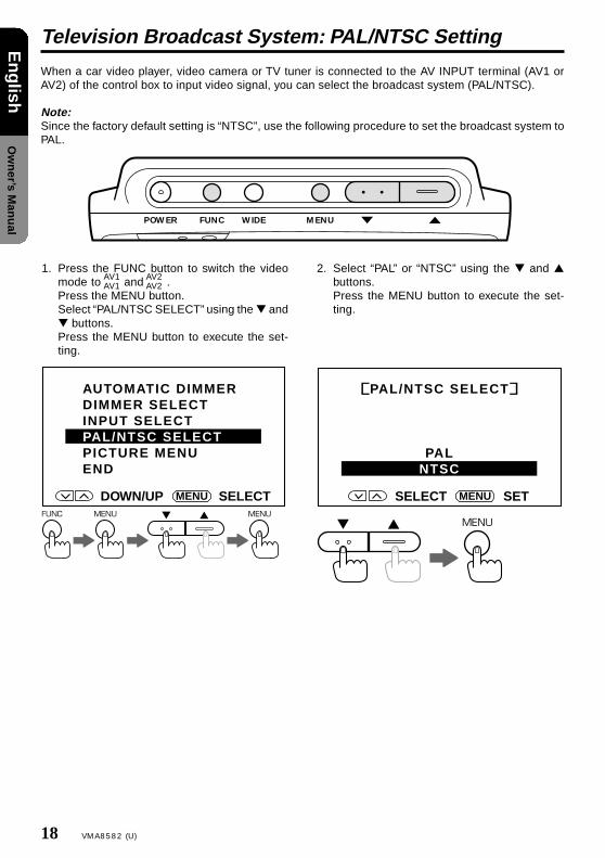
When a car video player, video camera or TV tuner is connected to the AV INPUT terminal (AV1 orAV2) of the control box to input video signal, you can select the broadcast system (PAL/NTSC).
Note:Since the factory default setting is “NTSC”, use the following procedure to set the broadcast system toPAL.
POWER FUNC WIDE MENU
1. Press the FUNC button to switch the videomode to and .Press the MENU button.Select “PAL/NTSC SELECT” using the ▼ and▼ buttons.Press the MENU button to execute the set-ting.
2. Select “PAL” or “NTSC” using the ▼ and ▲buttons.Press the MENU button to execute the set-ting.
Note:The characters other than “POWER”, “DISPLAY UNIT” and “RGB” are not marked on the control box.They are printed on the label located on the top of the unit.
6. CONNECTION OF EXTERNAL EQUIPMENT
POWER DISPLAY UNIT RGB
Rear view camera (back-eye camera), car video player or video camera
Video
Second monitor
Expansion AV output
TV tuner, car video player or video camera
Notes:• For the connection method, refer to page 29 of the “Installation / Wire Connection Manual”.• When a video camera monitor is connected to the control box and a howling noise is heard, one of
the following countermeasures should be taken.❈ Lower the volume of this unit.❈ Use earphones (if the earphones terminal is provided with the camera).❈ Put the camera microphone away from this unit.
20 VMA8582 (U)
En
glish
Ow
ner’s M
anu
al
Setting Example
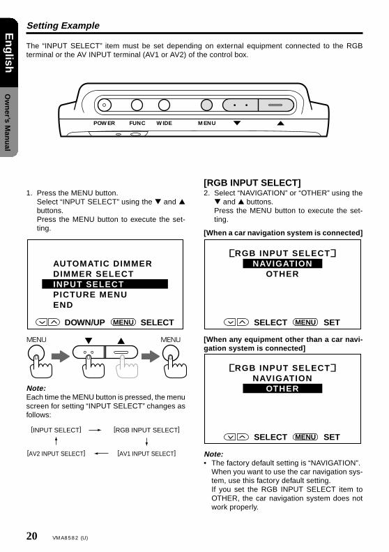
The “INPUT SELECT” item must be set depending on external equipment connected to the RGBterminal or the AV INPUT terminal (AV1 or AV2) of the control box.
POWER FUNC WIDE MENU
1. Press the MENU button.Select “INPUT SELECT” using the ▼ and ▲buttons.Press the MENU button to execute the set-ting.
Note:Each time the MENU button is pressed, the menuscreen for setting “INPUT SELECT” changes asfollows:
[RGB INPUT SELECT]2. Select “NAVIGATION” or “OTHER” using the
▼ and ▲ buttons.Press the MENU button to execute the set-ting.
[When a car navigation system is connected]
[When any equipment other than a car navi-gation system is connected]
Note:• The factory default setting is “NAVIGATION”.
When you want to use the car navigation sys-tem, use this factory default setting.If you set the RGB INPUT SELECT item toOTHER, the car navigation system does notwork properly.
[AV1 INPUT SELECT]3. Select “VIDEO” or “CAMERA” using the ▼ and
▲ buttons.Press the MENU button to execute the set-ting.
[When a rear view camera (back-eye camera)is connected]
[When a car video player or video camera isconnected or when no equipment is con-nected]
Notes:• The rear view camera (back-eye camera) must
be connected to the AV INPUT terminal (AV1only) of the control box.
• When the gear of the car is shifted to the “back”position, the monitor shows the image of therear view camera (back-eye camera).
• If “CAMERA” is selected for the AV1 INPUTSELECT item, the monitor always shows theimage of the rear view camera (back-eye cam-era).
[AV2 INPUT SELECT]4. Select “VIDEO” or “TV TUNER” using the ▼
and ▲ buttons.Press the MENU button to execute the set-ting.
[When a TV tuner is connected]
[When a car video player or video camera isconnected or when no equipment is con-nected]
Notes:• The TV tuner must be connected to the AV IN-
PUT terminal (AV2 only) of the control box.• If “TV TUNER” is selected for the AV2 INPUT
SELECT item, the video system is fixed toNTSC.
DOWN/UP SETMENU
AV1 INPUT SELECT
VIDEOCAMERA
DOWN/UP SETMENU
AV1 INPUT SELECT
VIDEOCAMERA
DOWN/UP SETMENU
AV2 INPUT SELECT
VIDEOTV TUNER
DOWN/UP SETMENU
AV2 INPUT SELECT
VIDEOTV TUNER
22 VMA8582 (U)
En
glish
Ow
ner’s M
anu
al
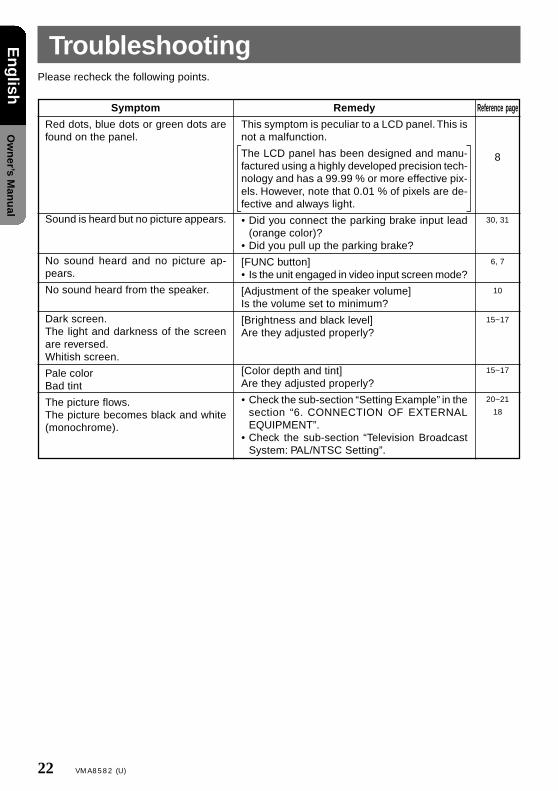
TroubleshootingPlease recheck the following points.
Symptom
Red dots, blue dots or green dots arefound on the panel.
Sound is heard but no picture appears.
No sound heard and no picture ap-pears.
No sound heard from the speaker.
Dark screen.The light and darkness of the screenare reversed.Whitish screen.
Pale colorBad tint
The picture flows.The picture becomes black and white(monochrome).
Reference page
8
30, 31
6, 7
10
15~17
15~17
20~21
18
Remedy
This symptom is peculiar to a LCD panel. This isnot a malfunction.
The LCD panel has been designed and manu-factured using a highly developed precision tech-nology and has a 99.99 % or more effective pix-els. However, note that 0.01 % of pixels are de-fective and always light.
• Did you connect the parking brake input lead(orange color)?
• Did you pull up the parking brake?
[FUNC button]• Is the unit engaged in video input screen mode?
[Adjustment of the speaker volume]Is the volume set to minimum?
[Brightness and black level]Are they adjusted properly?
[Color depth and tint]Are they adjusted properly?
• Check the sub-section “Setting Example” in thesection “6. CONNECTION OF EXTERNALEQUIPMENT”.
• Check the sub-section “Television BroadcastSystem: PAL/NTSC Setting”.
VMA8582(U) 23
En
glish
Ow
ner’s M
anu
al
GeneralModel No.: VMA8582 (with TV stand)Type: Liquid crystal color monitor unitPower supply voltage: DC 13.2V (exclusively for
a 12-volt car)Power consumption: 12 W (1.3 W at stand-by)Operating temperature range: 0˚C to +40˚CStorage temperature range: -20˚C to +80˚C
Control BoxConnection terminals : ACC power source input
: Rear view camera (back-eye) interrupt input
: Parking brake signal input: RGB input terminal: AV input 1, 2 terminal: AV output terminal
9. WARRANTY CERTIFICATE AND AFTER-SERVICE• First consult the store of purchase about the
repair, handling and maintenance of this prod-uct.
• When you encounter problems because youhave just relocated or this product was receivedas a gift, consult the “repair service center” onits repair. For other inquiries, consult the “cus-tomer service center”.
■ Warranty card (attached separately)You should ensure that the store of purchasefilled required items such as the date of pur-chase, name of the store, etc. After reading indetail, the warranty card should be stored awaycarefully.
Warranty period: 1 (one ) year from the dateof purchase
■ When repair is requiredRecheck the product to see if it has a break-down, according to the table on page 22. Ifbreakdown persists, switch off the power andcall the store of purchase.
• During the warranty period, the store of pur-chase will repair the defective product withinthe limits of warranty. You should deliver thedefective product with the warranty card.
• If the warranty expires, performance can bemaintained through repair. Repairs can bedone for a fee if the customer so desires. How-ever, the shortest storage period of perfor-mance parts for repair is 8 (eight) years afterthe end of manufacturing. (Performance partsare the critical parts which are required formaintenance of the product functioning.)
On fluorescent tubesThe fluorescent tubes used for this product havean expected life span. Beyond the life span, thefluorescent tubes do not function. In this case,they should be replaced with new ones.
Expectancy of life span: about 6 (six) to 7(seven) years (about 10, 000 hours) with useof 4 hours per day
When the fluorescent tubes do not function andrequire replacement, expert skills are necessary.You should consult the store of purchase.