20
Modeling Exercise Define the physics for a model of heat transfer by free convection using the manual approach with user-defined couplings
Modeling ExerciseDefine the physics for a model of heat transfer by free convection using the manual approach with user-defined couplings
Introduction
▪ This model exercise demonstrates the concept of multiphysics modeling in COMSOL Multiphysics®
▪ Define the physics for the model using the manual approach with user-defined couplings
Add and define the physics settings for the Laminar Flow (spf) interface, followed by the Heat Transfer in Fluids interface, and then manually couple the physics to simulate nonisothermal flow by including dependent variables of each physics interface as input to the other
• Enables you to manually implement couplings between physics interfaces for which no coupling features are available
▪ Important information for setting up the model can be found in the model specifications
Refer to this when building the model

Model Overview
▪ An array of heating tubes are submerged in a vessel of water with the fluid entering from the bottom
The model is reduced from 3D to 2D and further simplified by exploiting symmetry due to the array
▪ As fluid enters the vessel and travels past the heating element, heat is transferred through convection
An instance of nonisothermal flow
▪ The buoyancy force lifting the fluid is incorporated through a force term that depends on the temperature through the density
Modeled through a Volume Force domain feature
▪ Results include the velocity field, pressure distribution, and temperature distribution

Model Overview
A cross section (center) of the 3D model geometry (left) is taken, and symmetry of the array is exploited to result in the model geometry (right)
Model Specifications
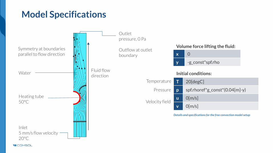
Details and specifications for the free convection model setup
Symmetry at boundaries parallel to flow direction
Inlet5 mm/s flow velocity20°C
Heating tube50°C
Outletpressure, 0 Pa
Outflow at outletboundary
Volume force lifting the fluid:
x 0
y -g_const*spf.rho
Initial conditions:
T 20[degC]
p spf.rhoref*g_const*(0.04[m]-y)
u 0[m/s]
v 0[m/s]
WaterFluid flow direction
Temperature
Pressure
Velocity field
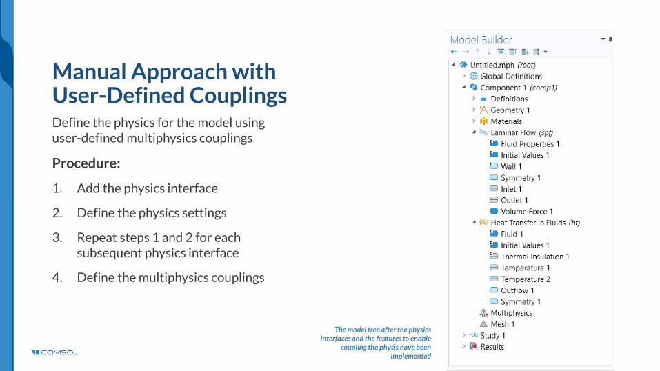
Manual Approach with User-Defined CouplingsDefine the physics for the model using user-defined multiphysics couplings
Procedure:
1. Add the physics interface
2. Define the physics settings
3. Repeat steps 1 and 2 for each subsequent physics interface
4. Define the multiphysics couplings
The model tree after the physics interfaces and the features to enable
coupling the physis have been implemented
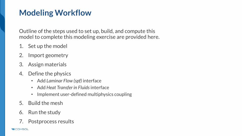
Modeling Workflow
Outline of the steps used to set up, build, and compute this model to complete this modeling exercise are provided here.
1. Set up the model
2. Import geometry
3. Assign materials
4. Define the physics
• Add Laminar Flow (spf) interface
• Add Heat Transfer in Fluids interface
• Implement user-defined multiphysics coupling
5. Build the mesh
6. Run the study
7. Postprocess results
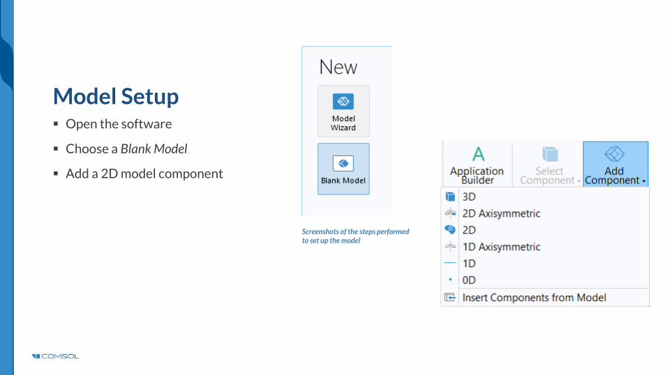
Model Setup▪ Open the software
▪ Choose a Blank Model
▪ Add a 2D model component
Screenshots of the steps performed to set up the model

▪ Download the geometry file free_convection.mphbin
▪ Import the geometry
▪ Build Form Union operation to finalize the geometry
Import Geometry
The Import button used and the free convection model geometry
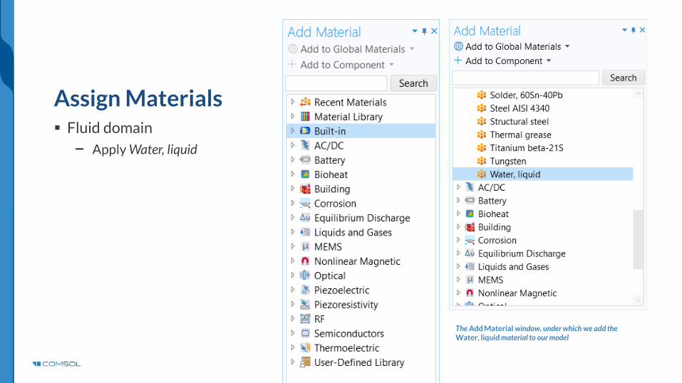
▪ Fluid domain
Apply Water, liquid
Assign Materials
The Add Material window, under which we add the Water, liquid material to our model

Manual Approach with User-Defined CouplingsDefine the physics for the model using user-defined multiphysics couplings
Procedure:
1. Add the physics interfaces
Laminar Flow (spf)
Heat Transfer in Fluids
2. Define the physics settings
3. Repeat steps 1 and 2 for each subsequent physics interface
4. Define the multiphysics couplings
Laminar Flow (spf) > Fluid Properties node
Heat Transfer in Fluids > Fluid nodeThe model tree after the physics
interfaces and the features to enable coupling the physics have been
implemented
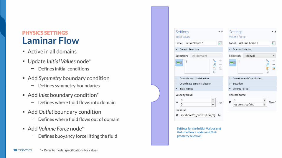
▪ Active in all domains
▪ Update Initial Values node*
Defines initial conditions
▪ Add Symmetry boundary condition
Defines symmetry boundaries
▪ Add Inlet boundary condition*
Defines where fluid flows into domain
▪ Add Outlet boundary condition
Defines where fluid flows out of domain
▪ Add Volume Force node*
Defines buoyancy force lifting the fluid
d
PHYSICS SETTINGS
Laminar Flow
Settings for the Initial Values and Volume Force nodes and their geometry selection
* = Refer to model specifications for values

PHYSICS SETTINGS
Heat Transfer in Fluids
Settings for the initial values (left) and the geometry selections for the inlet (center) and heater (right)
▪ Active in all domains
▪ Update Initial Values node*
Defines initial conditions
▪ Add Temperature boundary condition*
Defines temperature at inlet
▪ Add Temperature boundary condition*
Defines temperature of heater
▪ Add Outflow boundary condition
Defines outlet boundary
▪ Add Symmetry boundary condition
Defines symmetry boundaries
d
* = Refer to model specifications for values
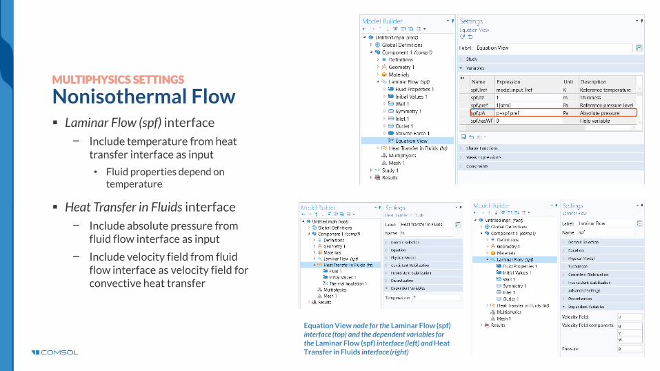
MULTIPHYSICS SETTINGS
Nonisothermal Flow▪ Laminar Flow (spf) interface
Include temperature from heat transfer interface as input
• Fluid properties depend on temperature
▪ Heat Transfer in Fluids interface
Include absolute pressure from fluid flow interface as input
Include velocity field from fluid flow interface as velocity field for convective heat transfer
Equation View node for the Laminar Flow (spf) interface (top) and the dependent variables for the Laminar Flow (spf) interface (left) and Heat Transfer in Fluids interface (right)
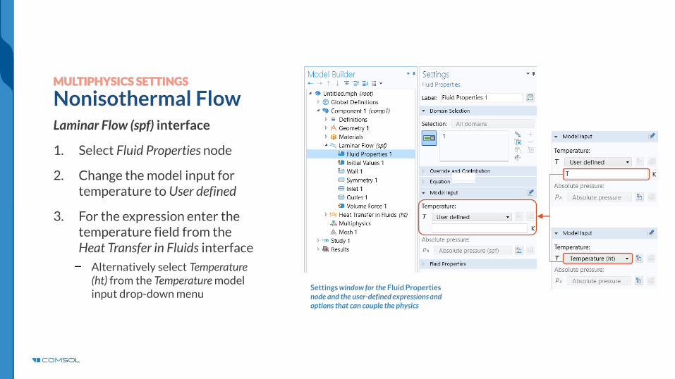
MULTIPHYSICS SETTINGS
Nonisothermal FlowLaminar Flow (spf) interface
1. Select Fluid Properties node
2. Change the model input for temperature to User defined
3. For the expression enter the temperature field from the Heat Transfer in Fluids interface
Alternatively select Temperature (ht) from the Temperature model input drop-down menu
Settings window for the Fluid Properties node and the user-defined expressions and options that can couple the physics
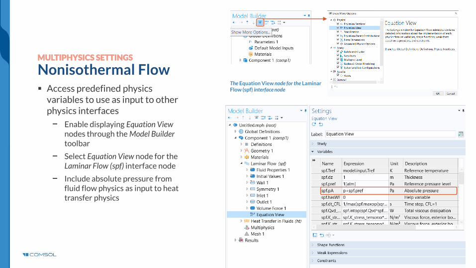
MULTIPHYSICS SETTINGS
Nonisothermal Flow▪ Access predefined physics
variables to use as input to other physics interfaces
Enable displaying Equation View nodes through the Model Builder toolbar
Select Equation View node for theLaminar Flow (spf) interface node
Include absolute pressure from fluid flow physics as input to heat transfer physics
The Equation View node for the Laminar Flow (spf) interface node
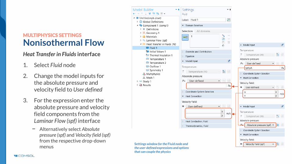
MULTIPHYSICS SETTINGS
Nonisothermal FlowHeat Transfer in Fluids interface
1. Select Fluid node
2. Change the model inputs for the absolute pressure and velocity field to User defined
3. For the expression enter the absolute pressure and velocity field components from the Laminar Flow (spf) interface
Alternatively select Absolute pressure (spf) and Velocity field (spf) from the respective drop-down menus
Settings window for the Fluid node and the user-defined expressions and options that can couple the physics

Build the mesh using the default settings
Build the Mesh
The setting used to generate the mesh for the free convection model, also pictured

Run the Study▪ Add a Stationary study
▪ Compute the model
Settings for the Stationary study being added to the model
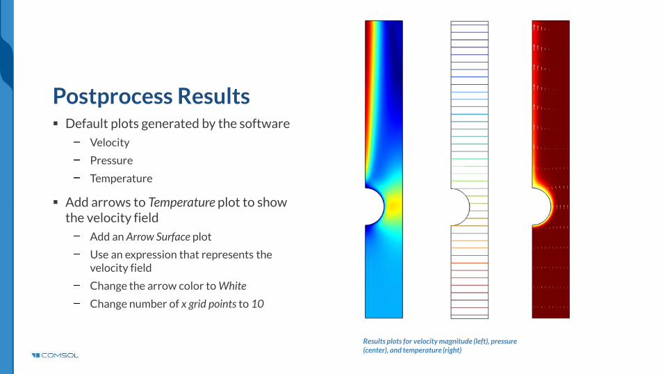
Postprocess Results▪ Default plots generated by the software
Velocity
Pressure
Temperature
▪ Add arrows to Temperature plot to show the velocity field
Add an Arrow Surface plot
Use an expression that represents the velocity field
Change the arrow color to White
Change number of x grid points to 10
Results plots for velocity magnitude (left), pressure (center), and temperature (right)


