45
Free Electrons. Kernel, drivers and embedded Linux development, consulting, training and support. http://free-electrons.com 1/45
Free Electrons. Kernel, drivers and embedded Linux development, consulting, training and support. http://free-electrons.com 1/45
Thomas Petazzoni
I CTO and Embedded Linux engineer at Free ElectronsI Embedded Linux development: kernel and driver
development, system integration, boot time and powerconsumption optimization, consulting, etc.
I Embedded Linux training, Linux driver development trainingand Android system development training, with materialsfreely available under a Creative Commons license.
I http://free-electrons.com
I ContributionsI Kernel support for the new Armada 370 and Armada XP
ARM SoCs from MarvellI Major contributor to Buildroot, an open-source, simple and
fast embedded Linux build system
I Living in Toulouse, south west of France
Free Electrons. Kernel, drivers and embedded Linux development, consulting, training and support. http://free-electrons.com 2/45
Agenda
I User perspective: booting with the Device Tree
I Basic Device Tree syntax and compilation
I Simple example of Device Tree fragment
I Overall organization of a Device Tree
I Examples of Device Tree usage
I General considerations about the Device Tree in Linux
Free Electrons. Kernel, drivers and embedded Linux development, consulting, training and support. http://free-electrons.com 3/45
User perspective: before the Device Tree
I The kernel contains the entire description of the hardware.I The bootloader loads a single binary, the kernel image, and
executes it.I uImage or zImage
I The bootloader prepares some additional information, calledATAGS, which address is passed to the kernel through registerr2
I Contains information such as memory size and location, kernelcommand line, etc.
I The bootloader tells the kernel on which board it is beingbooted through a machine type integer, passed in register r1.
I U-Boot command: bootm <kernel img addr>
I Barebox variable: bootm.image
Free Electrons. Kernel, drivers and embedded Linux development, consulting, training and support. http://free-electrons.com 4/45

User perspective: before the Device Tree
Free Electrons. Kernel, drivers and embedded Linux development, consulting, training and support. http://free-electrons.com 5/45
User perspective: booting with a Device Tree
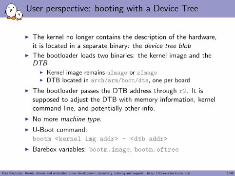
I The kernel no longer contains the description of the hardware,it is located in a separate binary: the device tree blob
I The bootloader loads two binaries: the kernel image and theDTB
I Kernel image remains uImage or zImageI DTB located in arch/arm/boot/dts, one per board
I The bootloader passes the DTB address through r2. It issupposed to adjust the DTB with memory information, kernelcommand line, and potentially other info.
I No more machine type.
I U-Boot command:bootm <kernel img addr> - <dtb addr>
I Barebox variables: bootm.image, bootm.oftree
Free Electrons. Kernel, drivers and embedded Linux development, consulting, training and support. http://free-electrons.com 6/45
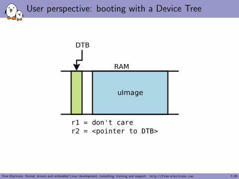
User perspective: booting with a Device Tree
Free Electrons. Kernel, drivers and embedded Linux development, consulting, training and support. http://free-electrons.com 7/45
User perspective: compatibility mode for DT booting
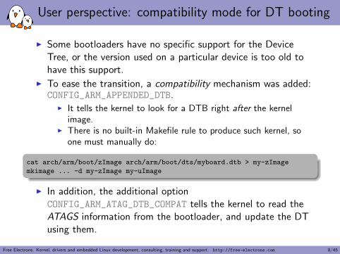
I Some bootloaders have no specific support for the DeviceTree, or the version used on a particular device is too old tohave this support.
I To ease the transition, a compatibility mechanism was added:CONFIG_ARM_APPENDED_DTB.
I It tells the kernel to look for a DTB right after the kernelimage.
I There is no built-in Makefile rule to produce such kernel, soone must manually do:
cat arch/arm/boot/zImage arch/arm/boot/dts/myboard.dtb > my-zImage
mkimage ... -d my-zImage my-uImage
I In addition, the additional optionCONFIG_ARM_ATAG_DTB_COMPAT tells the kernel to read theATAGS information from the bootloader, and update the DTusing them.
Free Electrons. Kernel, drivers and embedded Linux development, consulting, training and support. http://free-electrons.com 8/45
What is the Device Tree ?
I Quoted from the Power.org Standard for Embedded PowerArchitecture Platform Requirements (ePAPR)
I The ePAPR specifies a concept called a device tree to describesystem hardware. A boot program loads a device tree into aclient program’s memory and passes a pointer to the devicetree to the client.
I A device tree is a tree data structure with nodes that describethe physical devices in a system.
I An ePAPR-compliant device tree describes device informationin a system that cannot be dynamically detected by a clientprogram.
Free Electrons. Kernel, drivers and embedded Linux development, consulting, training and support. http://free-electrons.com 9/45
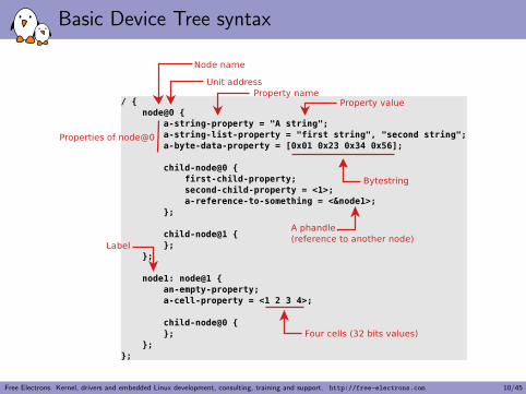
Basic Device Tree syntax
Free Electrons. Kernel, drivers and embedded Linux development, consulting, training and support. http://free-electrons.com 10/45
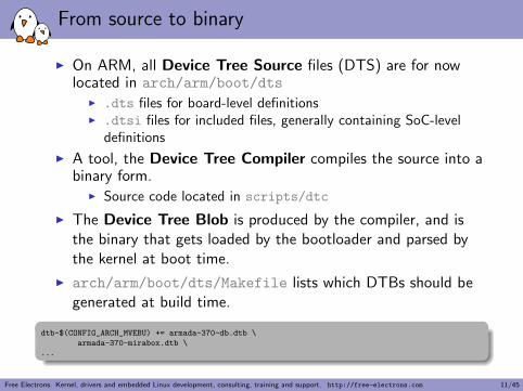
From source to binary
I On ARM, all Device Tree Source files (DTS) are for nowlocated in arch/arm/boot/dts
I .dts files for board-level definitionsI .dtsi files for included files, generally containing SoC-level
definitions
I A tool, the Device Tree Compiler compiles the source into abinary form.
I Source code located in scripts/dtc
I The Device Tree Blob is produced by the compiler, and isthe binary that gets loaded by the bootloader and parsed bythe kernel at boot time.
I arch/arm/boot/dts/Makefile lists which DTBs should begenerated at build time.
dtb-$(CONFIG_ARCH_MVEBU) += armada-370-db.dtb \
armada-370-mirabox.dtb \
...
Free Electrons. Kernel, drivers and embedded Linux development, consulting, training and support. http://free-electrons.com 11/45
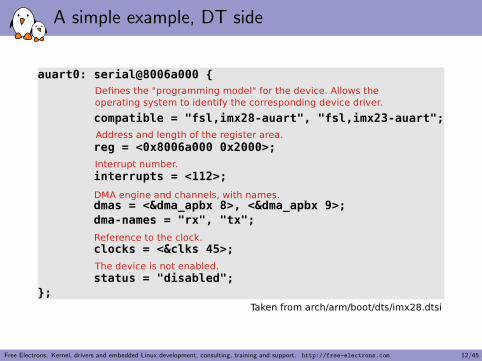
A simple example, DT side
Free Electrons. Kernel, drivers and embedded Linux development, consulting, training and support. http://free-electrons.com 12/45
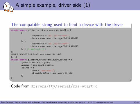
A simple example, driver side (1)
The compatible string used to bind a device with the driverstatic struct of_device_id mxs_auart_dt_ids[] = {
{
.compatible = "fsl,imx28-auart",
.data = &mxs_auart_devtype[IMX28_AUART]
}, {
.compatible = "fsl,imx23-auart",
.data = &mxs_auart_devtype[IMX23_AUART]
}, { /* sentinel */ }
};
MODULE_DEVICE_TABLE(of, mxs_auart_dt_ids);
[...]
static struct platform_driver mxs_auart_driver = {
.probe = mxs_auart_probe,
.remove = mxs_auart_remove,
.driver = {
.name = "mxs-auart",
.of_match_table = mxs_auart_dt_ids,
},
};
Code from drivers/tty/serial/mxs-auart.c
Free Electrons. Kernel, drivers and embedded Linux development, consulting, training and support. http://free-electrons.com 13/45
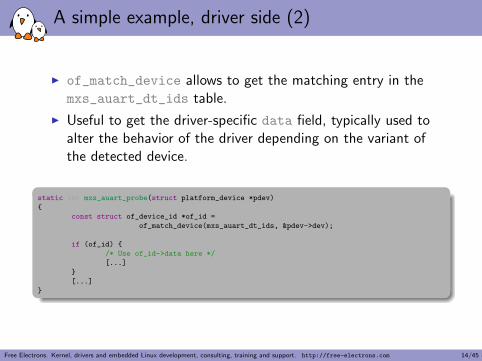
A simple example, driver side (2)
I of_match_device allows to get the matching entry in themxs_auart_dt_ids table.
I Useful to get the driver-specific data field, typically used toalter the behavior of the driver depending on the variant ofthe detected device.
static int mxs_auart_probe(struct platform_device *pdev)
{
const struct of_device_id *of_id =
of_match_device(mxs_auart_dt_ids, &pdev->dev);
if (of_id) {
/* Use of_id->data here */
[...]
}
[...]
}
Free Electrons. Kernel, drivers and embedded Linux development, consulting, training and support. http://free-electrons.com 14/45
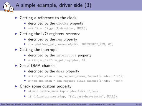
A simple example, driver side (3)
I Getting a reference to the clockI described by the clocks propertyI s->clk = clk_get(&pdev->dev, NULL);
I Getting the I/O registers resourceI described by the reg propertyI r = platform_get_resource(pdev, IORESOURCE_MEM, 0);
I Getting the interruptI described by the interrupts propertyI s->irq = platform_get_irq(pdev, 0);
I Get a DMA channelI described by the dmas propertyI s->rx_dma_chan = dma_request_slave_channel(s->dev, "rx");
I s->tx_dma_chan = dma_request_slave_channel(s->dev, "tx");
I Check some custom propertyI struct device_node *np = pdev->dev.of_node;
I if (of_get_property(np, "fsl,uart-has-rtscts", NULL))
Free Electrons. Kernel, drivers and embedded Linux development, consulting, training and support. http://free-electrons.com 15/45
Device Tree inclusion
I Device Tree files are not monolithic, they can be split inseveral files, including each other.
I .dtsi files are included files, while .dts files are final DeviceTrees
I Typically, .dtsi will contain definition of SoC-levelinformation (or sometimes definitions common to severalalmost identical boards).
I The .dts file contains the board-level information.
I The inclusion works by overlaying the tree of the includingfile over the tree of the included file.
I Inclusion using the DT operator /include/, or since a fewkernel releases, the DTS go through the C preprocessor, so#include is recommended.
Free Electrons. Kernel, drivers and embedded Linux development, consulting, training and support. http://free-electrons.com 16/45
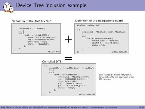
Device Tree inclusion example
Free Electrons. Kernel, drivers and embedded Linux development, consulting, training and support. http://free-electrons.com 17/45
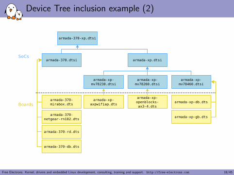
Device Tree inclusion example (2)
Free Electrons. Kernel, drivers and embedded Linux development, consulting, training and support. http://free-electrons.com 18/45
Concept of Device Tree binding
I Quoting the ePAPR:I This chapter contains requirements, known as bindings, for
how specific types and classes of devices are representedin the device tree.
I The compatible property of a device node describes thespecific binding (or bindings) to which the node complies.
I When creating a new device tree representation for a device, abinding should be created that fully describes therequired properties and value of the device. This set ofproperties shall be sufficiently descriptive to provide devicedrivers with needed attributes of the device.
Free Electrons. Kernel, drivers and embedded Linux development, consulting, training and support. http://free-electrons.com 19/45
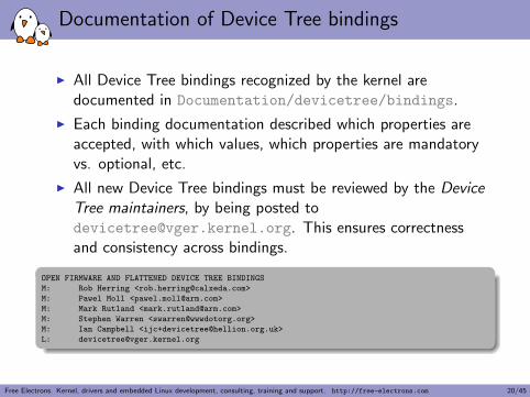
Documentation of Device Tree bindings
I All Device Tree bindings recognized by the kernel aredocumented in Documentation/devicetree/bindings.
I Each binding documentation described which properties areaccepted, with which values, which properties are mandatoryvs. optional, etc.
I All new Device Tree bindings must be reviewed by the DeviceTree maintainers, by being posted [email protected]. This ensures correctnessand consistency across bindings.
OPEN FIRMWARE AND FLATTENED DEVICE TREE BINDINGS
M: Rob Herring <[email protected]>
M: Pawel Moll <[email protected]>
M: Mark Rutland <[email protected]>
M: Stephen Warren <[email protected]>
M: Ian Campbell <[email protected]>
Free Electrons. Kernel, drivers and embedded Linux development, consulting, training and support. http://free-electrons.com 20/45
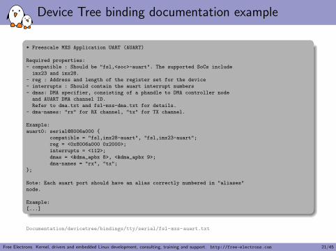
Device Tree binding documentation example
* Freescale MXS Application UART (AUART)
Required properties:
- compatible : Should be "fsl,<soc>-auart". The supported SoCs include
imx23 and imx28.
- reg : Address and length of the register set for the device
- interrupts : Should contain the auart interrupt numbers
- dmas: DMA specifier, consisting of a phandle to DMA controller node
and AUART DMA channel ID.
Refer to dma.txt and fsl-mxs-dma.txt for details.
- dma-names: "rx" for RX channel, "tx" for TX channel.
Example:
auart0: serial@8006a000 {
compatible = "fsl,imx28-auart", "fsl,imx23-auart";
reg = <0x8006a000 0x2000>;
interrupts = <112>;
dmas = <&dma_apbx 8>, <&dma_apbx 9>;
dma-names = "rx", "tx";
};
Note: Each auart port should have an alias correctly numbered in "aliases"
node.
Example:
[...]
Documentation/devicetree/bindings/tty/serial/fsl-mxs-auart.txt
Free Electrons. Kernel, drivers and embedded Linux development, consulting, training and support. http://free-electrons.com 21/45
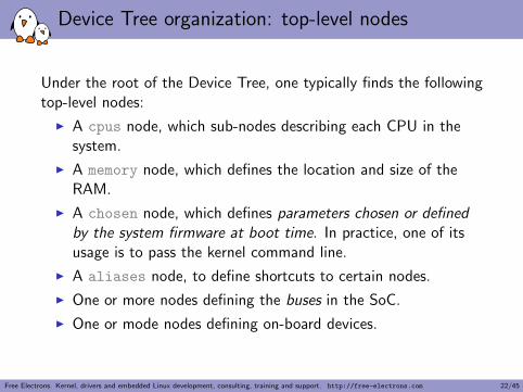
Device Tree organization: top-level nodes
Under the root of the Device Tree, one typically finds the followingtop-level nodes:
I A cpus node, which sub-nodes describing each CPU in thesystem.
I A memory node, which defines the location and size of theRAM.
I A chosen node, which defines parameters chosen or definedby the system firmware at boot time. In practice, one of itsusage is to pass the kernel command line.
I A aliases node, to define shortcuts to certain nodes.
I One or more nodes defining the buses in the SoC.
I One or mode nodes defining on-board devices.
Free Electrons. Kernel, drivers and embedded Linux development, consulting, training and support. http://free-electrons.com 22/45
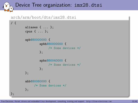
Device Tree organization: imx28.dtsi
arch/arm/boot/dts/imx28.dtsi
/ {
aliases { ... };
cpus { ... };
apb@80000000 {
apbh@80000000 {
/* Some devices */
};
apbx@80040000 {
/* Some devices */
};
};
ahb@80080000 {
/* Some devices */
};
};
Free Electrons. Kernel, drivers and embedded Linux development, consulting, training and support. http://free-electrons.com 23/45
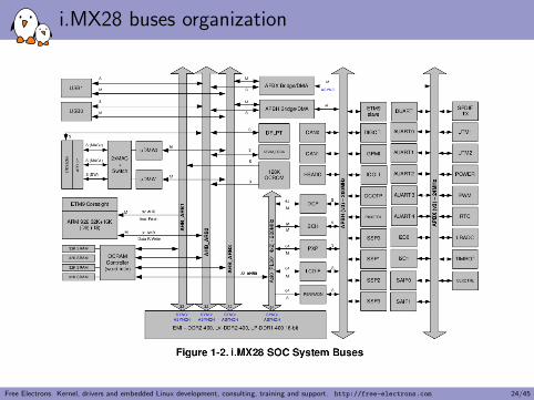
i.MX28 buses organization
Free Electrons. Kernel, drivers and embedded Linux development, consulting, training and support. http://free-electrons.com 24/45
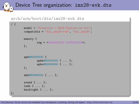
Device Tree organization: imx28-evk.dts
arch/arm/boot/dts/imx28-evk.dts/ {
model = "Freescale i.MX28 Evaluation Kit";
compatible = "fsl,imx28-evk", "fsl,imx28";
memory {
reg = <0x40000000 0x08000000>;
};
apb@80000000 {
apbh@80000000 { ... };
apbx@80040000 { ... };
};
ahb@80080000 { ... };
sound { ... };
leds { ... };
backlight { ... };
};
Free Electrons. Kernel, drivers and embedded Linux development, consulting, training and support. http://free-electrons.com 25/45
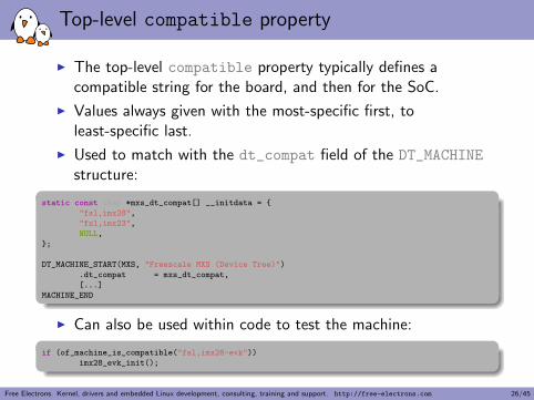
Top-level compatible property
I The top-level compatible property typically defines acompatible string for the board, and then for the SoC.
I Values always given with the most-specific first, toleast-specific last.
I Used to match with the dt_compat field of the DT_MACHINE
structure:
static const char *mxs_dt_compat[] __initdata = {
"fsl,imx28",
"fsl,imx23",
NULL,
};
DT_MACHINE_START(MXS, "Freescale MXS (Device Tree)")
.dt_compat = mxs_dt_compat,
[...]
MACHINE_END
I Can also be used within code to test the machine:
if (of_machine_is_compatible("fsl,imx28-evk"))
imx28_evk_init();
Free Electrons. Kernel, drivers and embedded Linux development, consulting, training and support. http://free-electrons.com 26/45

Bus, address cells and size cells
Inside a bus, one typically needs to define the following properties:
I A compatible property, which identifies the bus controller (incase of I2C, SPI, PCI, etc.). A special valuecompatible = "simple-bus" means a simplememory-mapped bus with no specific handling or driver. Childnodes will be registered as platform devices.
I The #address-cells property indicate how many cells (i.e32 bits values) are needed to form the base address part in thereg property.
I The #size-cells is the same, for the size part of the reg
property.
I The ranges property can describe an address translationbetween the child bus and the parent bus. When simplydefined as ranges;, it means that the translation is anidentity translation.
Free Electrons. Kernel, drivers and embedded Linux development, consulting, training and support. http://free-electrons.com 27/45
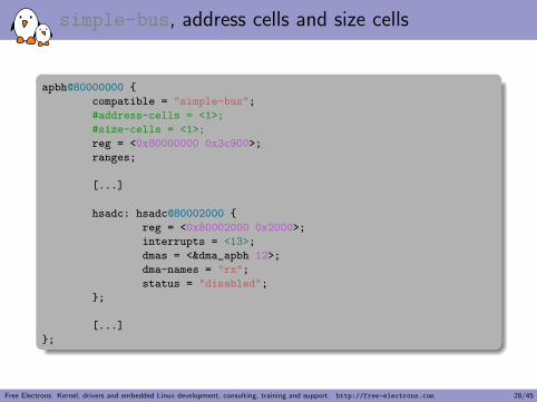
simple-bus, address cells and size cells
apbh@80000000 {
compatible = "simple-bus";
#address-cells = <1>;
#size-cells = <1>;
reg = <0x80000000 0x3c900>;
ranges;
[...]
hsadc: hsadc@80002000 {
reg = <0x80002000 0x2000>;
interrupts = <13>;
dmas = <&dma_apbh 12>;
dma-names = "rx";
status = "disabled";
};
[...]
};
Free Electrons. Kernel, drivers and embedded Linux development, consulting, training and support. http://free-electrons.com 28/45
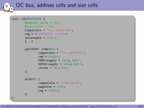
I2C bus, address cells and size cells
i2c0: i2c@80058000 {
#address-cells = <1>;
#size-cells = <0>;
compatible = "fsl,imx28-i2c";
reg = <0x80058000 0x2000>;
interrupts = <111>;
[...]
sgtl5000: codec@0a {
compatible = "fsl,sgtl5000";
reg = <0x0a>;
VDDA-supply = <®_3p3v>;
VDDIO-supply = <®_3p3v>;
clocks = <&saif0>;
};
at24@51 {
compatible = "at24,24c32";
pagesize = <32>;
reg = <0x51>;
};
};
Free Electrons. Kernel, drivers and embedded Linux development, consulting, training and support. http://free-electrons.com 29/45
Interrupt handling
I interrupt-controller; is a boolean property thatindicates that the current node is an interrupt controller.
I #interrupt-cells indicates the number of cells in theinterrupts property for the interrupts managed by theselected interrupt controller.
I interrupt-parent is a phandle that points to the interruptcontroller for the current node. There is generally a top-levelinterrupt-parent definition for the main interruptcontroller.
Free Electrons. Kernel, drivers and embedded Linux development, consulting, training and support. http://free-electrons.com 30/45
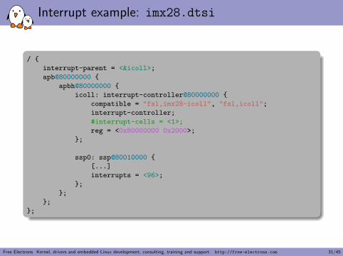
Interrupt example: imx28.dtsi
/ {
interrupt-parent = <&icoll>;
apb@80000000 {
apbh@80000000 {
icoll: interrupt-controller@80000000 {
compatible = "fsl,imx28-icoll", "fsl,icoll";
interrupt-controller;
#interrupt-cells = <1>;
reg = <0x80000000 0x2000>;
};
ssp0: ssp@80010000 {
[...]
interrupts = <96>;
};
};
};
};
Free Electrons. Kernel, drivers and embedded Linux development, consulting, training and support. http://free-electrons.com 31/45
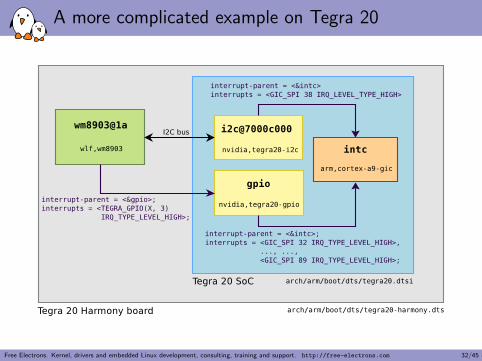
A more complicated example on Tegra 20
Free Electrons. Kernel, drivers and embedded Linux development, consulting, training and support. http://free-electrons.com 32/45
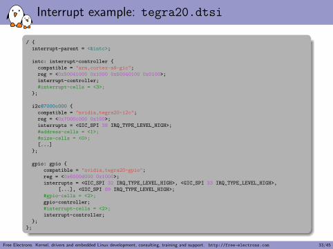
Interrupt example: tegra20.dtsi
/ {
interrupt-parent = <&intc>;
intc: interrupt-controller {
compatible = "arm,cortex-a9-gic";
reg = <0x50041000 0x1000 0x50040100 0x0100>;
interrupt-controller;
#interrupt-cells = <3>;
};
i2c@7000c000 {
compatible = "nvidia,tegra20-i2c";
reg = <0x7000c000 0x100>;
interrupts = <GIC_SPI 38 IRQ_TYPE_LEVEL_HIGH>;
#address-cells = <1>;
#size-cells = <0>;
[...]
};
gpio: gpio {
compatible = "nvidia,tegra20-gpio";
reg = <0x6000d000 0x1000>;
interrupts = <GIC_SPI 32 IRQ_TYPE_LEVEL_HIGH>, <GIC_SPI 33 IRQ_TYPE_LEVEL_HIGH>,
[...], <GIC_SPI 89 IRQ_TYPE_LEVEL_HIGH>;
#gpio-cells = <2>;
gpio-controller;
#interrupt-cells = <2>;
interrupt-controller;
};
};
Free Electrons. Kernel, drivers and embedded Linux development, consulting, training and support. http://free-electrons.com 33/45
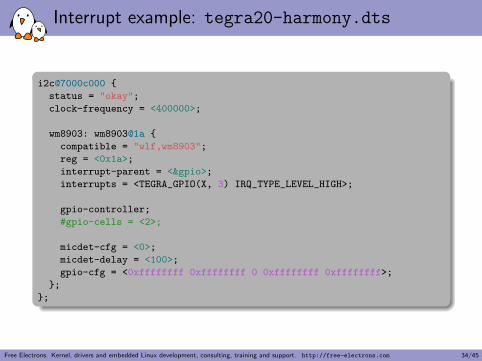
Interrupt example: tegra20-harmony.dts
i2c@7000c000 {
status = "okay";
clock-frequency = <400000>;
wm8903: wm8903@1a {
compatible = "wlf,wm8903";
reg = <0x1a>;
interrupt-parent = <&gpio>;
interrupts = <TEGRA_GPIO(X, 3) IRQ_TYPE_LEVEL_HIGH>;
gpio-controller;
#gpio-cells = <2>;
micdet-cfg = <0>;
micdet-delay = <100>;
gpio-cfg = <0xffffffff 0xffffffff 0 0xffffffff 0xffffffff>;
};
};
Free Electrons. Kernel, drivers and embedded Linux development, consulting, training and support. http://free-electrons.com 34/45
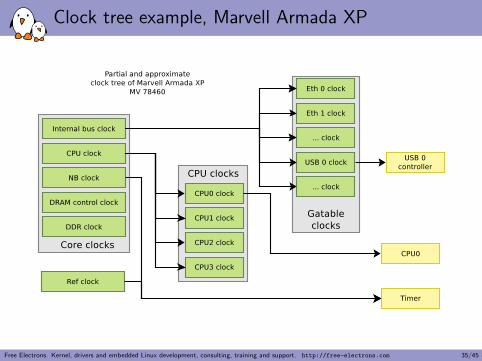
Clock tree example, Marvell Armada XP
Free Electrons. Kernel, drivers and embedded Linux development, consulting, training and support. http://free-electrons.com 35/45
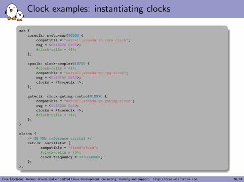
Clock examples: instantiating clocks
soc {
coreclk: mvebu-sar@18230 {
compatible = "marvell,armada-xp-core-clock";
reg = <0x18230 0x08>;
#clock-cells = <1>;
};
cpuclk: clock-complex@18700 {
#clock-cells = <1>;
compatible = "marvell,armada-xp-cpu-clock";
reg = <0x18700 0xA0>;
clocks = <&coreclk 1>;
};
gateclk: clock-gating-control@18220 {
compatible = "marvell,armada-xp-gating-clock";
reg = <0x18220 0x4>;
clocks = <&coreclk 0>;
#clock-cells = <1>;
};
}
clocks {
/* 25 MHz reference crystal */
refclk: oscillator {
compatible = "fixed-clock";
#clock-cells = <0>;
clock-frequency = <25000000>;
};
};
Free Electrons. Kernel, drivers and embedded Linux development, consulting, training and support. http://free-electrons.com 36/45
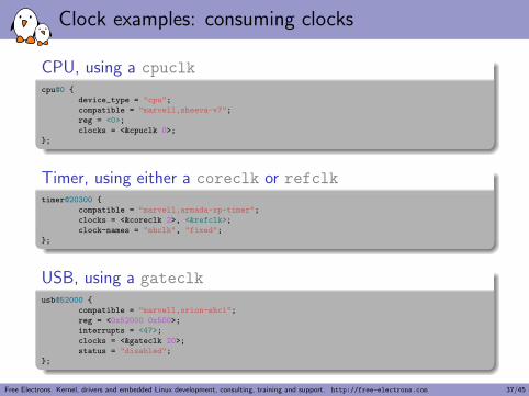
Clock examples: consuming clocks
CPU, using a cpuclkcpu@0 {
device_type = "cpu";
compatible = "marvell,sheeva-v7";
reg = <0>;
clocks = <&cpuclk 0>;
};
Timer, using either a coreclk or refclktimer@20300 {
compatible = "marvell,armada-xp-timer";
clocks = <&coreclk 2>, <&refclk>;
clock-names = "nbclk", "fixed";
};
USB, using a gateclkusb@52000 {
compatible = "marvell,orion-ehci";
reg = <0x52000 0x500>;
interrupts = <47>;
clocks = <&gateclk 20>;
status = "disabled";
};
Free Electrons. Kernel, drivers and embedded Linux development, consulting, training and support. http://free-electrons.com 37/45
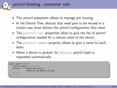
pinctrl binding: consumer side
I The pinctrl subsystem allows to manage pin muxing.
I In the Device Tree, devices that need pins to be muxed in acertain way must declare the pinctrl configuration they need.
I The pinctrl-<n> properties allow to give the list of pinctrlconfiguration needed for a certain state of the device.
I The pinctrl-names property allows to give a name to eachstate.
I When a device is probed, its default pinctrl state isrequested automatically.
ssp0: ssp@80010000 {
pinctrl-names = "default";
pinctrl-0 = <&mmc0_8bit_pins_a
&mmc0_cd_cfg &mmc0_sck_cfg>;
[...]
};
Free Electrons. Kernel, drivers and embedded Linux development, consulting, training and support. http://free-electrons.com 38/45
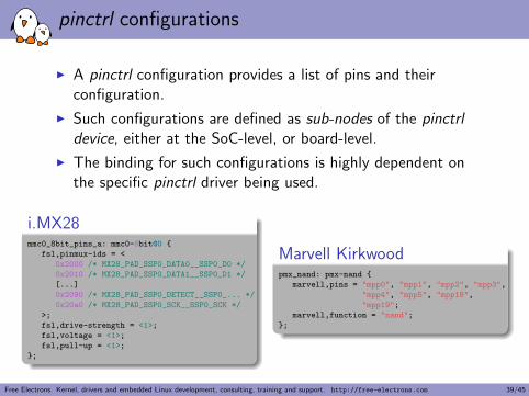
pinctrl configurations
I A pinctrl configuration provides a list of pins and theirconfiguration.
I Such configurations are defined as sub-nodes of the pinctrldevice, either at the SoC-level, or board-level.
I The binding for such configurations is highly dependent onthe specific pinctrl driver being used.
i.MX28mmc0_8bit_pins_a: mmc0-8bit@0 {
fsl,pinmux-ids = <
0x2000 /* MX28_PAD_SSP0_DATA0__SSP0_D0 */
0x2010 /* MX28_PAD_SSP0_DATA1__SSP0_D1 */
[...]
0x2090 /* MX28_PAD_SSP0_DETECT__SSP0_... */
0x20a0 /* MX28_PAD_SSP0_SCK__SSP0_SCK */
>;
fsl,drive-strength = <1>;
fsl,voltage = <1>;
fsl,pull-up = <1>;
};
Marvell Kirkwoodpmx_nand: pmx-nand {
marvell,pins = "mpp0", "mpp1", "mpp2", "mpp3",
"mpp4", "mpp5", "mpp18",
"mpp19";
marvell,function = "nand";
};
Free Electrons. Kernel, drivers and embedded Linux development, consulting, training and support. http://free-electrons.com 39/45
DT is hardware description, not configuration
I The Device Tree is really a hardware description language.
I It should describe the hardware layout, and how it works.
I But it should not describe which particular hardwareconfiguration you’re interested in.
I As an example:I You may describe in the DT whether a particular piece of
hardware supports DMA or not.I But you may not describe in the DT if you want to use DMA
or not.
Free Electrons. Kernel, drivers and embedded Linux development, consulting, training and support. http://free-electrons.com 40/45
DT bindings as an ABI
I Since the DT is OS independent, it should also be stable.
I The original idea is that DTBs can be flashed on some devicesby the manufacturer, so that the user can install whicheveroperating system it wants.
I Once a Device Tree binding is defined, and used in DTBs, itshould no longer be changed anymore. It can only beextended.
I This normally means that Device Tree bindings becomepart of the kernel ABI, and it should be handled with thesame care.
I However, kernel developers are realizing that this is really hardto achieve and slowing down the integration of drivers.
I The ARM Kernel Mini-summit discussions have relaxed thoserules.
I There will be additional discussions during the Kernel Summit,with final conclusions published afterwards.
Free Electrons. Kernel, drivers and embedded Linux development, consulting, training and support. http://free-electrons.com 41/45
Basic guidelines for binding design
I A precise compatible string is better than a vague oneI You have a driver that covers both variants T320 and T330 of
your hardware. You may be tempted to use foo,t3xx as yourcompatible string.
I Bad idea: what if T340 is slightly different, in an incompatibleway? You’d better use foo,t320 for both T320 and T330.
I Do not encode too much hardware details in the DTI When two hardware variants are quite similar, some developers
are tempted to encode all the differences in the DT, includingregister offsets, bit masks or offsets.
I Bad idea: it makes the binding more complex, and thereforeless resilient to future changes. Instead, use two differentcompatible strings and handle the differences in the driver.
Free Electrons. Kernel, drivers and embedded Linux development, consulting, training and support. http://free-electrons.com 42/45
Future directions
I More DT bindings for various subsystemsI A tool to validate DTS against bindings
I Currently, the DT compiler only makes syntax checks, noconformance checks against bindings.
I Proposal from Benoit Cousson and Fabien Parent,[RFC 00/15] Device Tree schemas and validation
I Take out the Device Tree source files from the kerneltree
I DTs are OS independent, so they can be used for otherpurposes than just Linux. They are already used by Barebox orU-Boot.
I Having them outside of the kernel reduces the amount ofchurn in the kernel source.
I But is IMO likely to cause a huge number of compatibilityissues.
Free Electrons. Kernel, drivers and embedded Linux development, consulting, training and support. http://free-electrons.com 43/45
References
I Power.orgTM Standard for Embedded Power ArchitecturePlatform Requirements (ePAPR), http://www.power.org/resources/downloads/Power_ePAPR_APPROVED_v1.0.pdf
I DeviceTree.org website, http://www.devicetree.org
I Device Tree documentation in the kernel sources,Documentation/devicetree
I The Device Tree kernel mailing list, http://dir.gmane.org/gmane.linux.drivers.devicetree
Free Electrons. Kernel, drivers and embedded Linux development, consulting, training and support. http://free-electrons.com 44/45
Questions?
Thomas Petazzoni
Slides under CC-BY-SA 3.0http://free-electrons.com/pub/conferences/2013/elce/petazzoni-device-
tree-dummies/
Free Electrons. Kernel, drivers and embedded Linux development, consulting, training and support. http://free-electrons.com 45/45


