by Grant M More8/16 bit ApplicationsFreescale, East Kilbride
Introduction
This document describes an audio reproduction technique that may be employed on any HCS12 series microcontroller (MCU) with pulse-width modulation (PWM) capability. The approach is optimised in that it uses a minimal number of components external to the MCU, and when reproducing stored sample data, is almost completely passive in relation to processor core usage.
This document focuses on the reproduction of .WAV files, primarily because they are commonly available, uncompressed, and easy to manipulate. There is no reason, however, why the technique should not be applied to other file formats.
Another technique is described, in addition to the sample reproduction technique, which allows simple warning noises to be created from basic mathematical algorithms.
The HCS12 series of microcontrollers does not support dedicated internal digital-to-analogue conversion hardware, and thus external hardware, perhaps in the form of a digital-to-analogue conversion IC, is required to perform the necessary manipulation. This approach may be well justified if the process data is high quality, high bit rate audio, for example a bit stream within a CD player. The use of an external digital-to-analog converter (DAC) in this context is justified primarily by the benefit given from the device, offset by the relatively high cost.
In applications where a requirement exists for audio reproduction, but the cost of a DAC precludes external conversion, the technique described here may be a prime solution. An example of this may be a security alarm control panel where a microcontroller is employed to perform the user interaction and system control functions. Communication with the user could be improved with the implementation of sound capability, perhaps only the generation of beeps, dings and alarm functions, or perhaps issuing clear, concise voice instructions. Both are easily possible.
The basic principle of audio reproduction using the PWM module involves using sampled data to vary the duty cycle of a PWM signal, the period of which is held at a constant value. The signal produced by the PWM module is then fed to a low-pass filter, which effectively integrates the pulsed data and produces a signal that is decipherable by the human ear.
2 Audio Reproduction on HCS12 Microcontrollers
For More Information On This Product, Go to: www.freescale.com
AN2250/DSoftware
F
ree
sca
le S
em
ico
nd
uc
tor,
I
Freescale Semiconductor, Inc.n
c..
.
Software
Principle The basic purpose of the software is to use either stored data samples, or an algorithm to produce samples in real-time, to directly change the duty cycle of a PWM signal. This task is relatively straightforward: a simple case of loading the PWM duty register at intervals specified by a strategically set timer. The more complex task is taking data in a manageable form, namely .WAV data, and passing this to the HCS12 MCU in a format that can be easily stored and retrieved.
Storing and Retrieving Sample Data
In order to accomplish the storage and retrieval task, raw sample data is stripped from a .WAV file by a run-time utility which creates a number of 16kb ASCII arrays of the type which can be handled by the coding environment. Each array can then be loaded into a 16kb discrete flash memory page, and accessed with a far data pointer. Each page can then be accessed sequentially and the data read out as one audio stream.
The binary data is converted to ASCII to allow the development environment to handle the arrays. This creates run-time array files that are a great deal larger than 16kb, but the compiler stores these as the original 16kb of binary data within the flash memory.
A variation on this is the provision for storing a number of discrete audio samples in individual pages. These could then be accessed individually and allow a number of samples to be reproduced independently. This may have application in systems where a number of short samples, perhaps voice commands, need to be reproduced.
Audio Reproduction on HCS12 Microcontrollers 3
For More Information On This Product, Go to: www.freescale.com
AN2250/D
F
ree
sca
le S
em
ico
nd
uc
tor,
I
Freescale Semiconductor, Inc.n
c..
.
.WAV Files .WAV files have a standard format that contains sample data and a header describing the format and contents of the file. It is important to check the format of the file to be downloaded to the HCS12 MCU, as reading a file of an unexpected format will result in corrupt sample data. Reading the value of a number of the parameters stored in the header and comparing these to the values expected authenticates the format of the file. This is the method used to check the validity of the .WAV file in the accompanying example source code.
The critical parameters that should always be checked are:
• The magic number used to define the file as a type .WAV (Hex 52494646)
• Number of channels• Sample rate• Number of bytes per sample
The length of the raw data (specified in bytes 4-7 of the DATA chunk) can be copied from the .WAV file and used to determine the memory page requirement. This value is also used to determine the code length for each page (all pages = 16kb except the last page), which is written as the first two bytes to the beginning of each array (page) in order to allow the playback code to detect the size and end of the file.
Choosing Sample Rate
The sample rate depends entirely on the application. The final choice is a trade-off between intelligibility and sample storage (time) capability. Commonly available sample rates are:
• 8kHz telephone quality• 11.025 kHz AM radio quality• 22.05kHz TV/FM radio quality• 44.1kHz CD quality
There is no reason, however, why the sample rate cannot be chosen out with these values, especially if the .WAV data is obtained from a file upon the creation of which the sample rate was selectable. In theory, the sample rate determines the bandwidth available for reproduction, and by the Nyquist Criterion, the highest frequency that can be reproduced accurately at a sample rate of z kHz is z/2 kHz.
The scope of application for this reproduction technique is such that it is unlikely that the 22.05/44.1kHz sample rates be used. In relation to Figure 2, it is clear that these sample rates demand a much greater storage requirement, and are thus likely to be quite impractical, though not impossible. In practice, an 11.025kHz sample rate has yielded good results. Speech is entirely clear and intelligible, and music data is equally good, though one must take into account the bandwidth limitation imposed by the lower sample rate.
4 Audio Reproduction on HCS12 Microcontrollers
For More Information On This Product, Go to: www.freescale.com
AN2250/DSoftware
F
ree
sca
le S
em
ico
nd
uc
tor,
I
Freescale Semiconductor, Inc.n
c..
.
Simple Beeps and Alarm Sounds
By generating sample data in real time with the use of an algorithm, it is possible to eliminate the requirement for sample storage space. Clearly this is not practical for reproducing speech, music or any type of randomly varying audio signal, as the algorithm would be extremely complex. However, simple beeps and warning signals may be constructed with comparative ease.
The two parameters that can be controlled directly from software are the PWM duty cycle and the PWM period length. A simple sinusoidal output can be achieved by cycling the PWM duty cycle register, and a delay introduced into the register write operation can be used to control the pitch of the signal. This procedure forms the basis of a simple beep, where the sinusoid is applied and withdrawn after a set amount of time.
The PWM period length register can be used in conjunction with the PWM duty cycle register to control the amplitude of the output signal. As the PWM period decreases, the maximum possible amplitude of the output signal is proportionally reduced. This can be used to produce a number of interesting effects including alarm sounds, signal fades and cyclic warning noises. A degree of experimentation can yield a range of different outputs, a sample of which are demonstrated in the accompanying source code.
Reproducing Audio As has been previously described, the task of reproducing the audio is accomplished by loading the PWM duty register with values pointed to by the far type data pointer. The timing of the samples is controlled by the modulus down counter, which interrupts and activates an ISR to perform the required PWM register and pointer servicing.
The modulus down counter operates by counting down from a prescribed value and generating an interrupt when zero is reached, then reloading the prescribed value and starting again. This gives good flexibility in this application as any practical sample rate can be reproduced by setting the appropriate count start value. This can be calculated by identifying the down counter count rate (set to bus clock in example source code), and identifying how many bus clock cycles should pass between sample write operations to the PWM duty register. For example, the modulus down counter on an HCS12 MCU, operating from a 32MHz crystal with a 16MHz bus clock will down count once every 62.5nS (assuming that the bus clock is used as the counter clock). To reproduce a sample at a sample rate of 11.025kHz the counter will need to count down from 1451 (hex 0x05AB). This ensures that the samples are scheduled at the correct rate.
Audio Reproduction on HCS12 Microcontrollers 5
For More Information On This Product, Go to: www.freescale.com
AN2250/D
F
ree
sca
le S
em
ico
nd
uc
tor,
I
Freescale Semiconductor, Inc.n
c..
.
Reproducing Multi-channel/Stereo Audio
Stereo samples may be reproduced by making use of a second PWM channel. The channels can therefore be assigned one to the left channel, the other to the right channel. Data can then be read from the stored data file in pairs, the relative data being passed to the correct PWM channel. This is straightforward as data is stored in a .WAV file as a series of sequential sample pairs format as shown in Figure 1.
Figure 1. Arrangement of Samples Within a Stereo .WAV File
Although entirely possible, the stereo reproduction technique halves the available reproduction time, and thus makes the implementation much less attractive.
A much more practical use for two PWM channels may be to use the second channel to drive a second loudspeaker in a different location. This would allow both loudspeakers to operate simultaneously, reproducing different samples. An example of this is again the use of the MCU in a security alarm circuit. On intruder detection, one PWM channel could be used to generate the alarm sound for the external siren on the outside of the building, while the other could be used to sound a different alarm inside the building.
Using this technique, a maximum of eight separate channels could be used, each reproducing a different sample. For example, a third PWM channel could be used to reproduce a stored sample detailing the address of the protected property, which is relayed by telephone line to the police.
Reproducing 16-bit Samples
The PWM module on HCS12 series microcontrollers supports 16-bit PWM operation. This provides 16-bit duty cycle resolution, and thus it is technically possible to load 16-bit sample data to the PWM. The concatenation of two PWM channels has the effect that the PWM period is increased by a factor of 256 and therefore, the sample reproduction rate capability is reduced by a factor of 256. Furthermore, the use of 16-bit samples halves the playback time capability of the MCU and will not yield a vast increase in audio quality, especially if the passive RC low-pass filter is implemented.
The practical consequences of 16-bit sample reproduction have not been fully investigated, but it is absolutely possible.
Left 1 Right 1 Left 2 Right 2 Left 3 Right 3 Etc.
6 Audio Reproduction on HCS12 Microcontrollers
For More Information On This Product, Go to: www.freescale.com
AN2250/DHardware
F
ree
sca
le S
em
ico
nd
uc
tor,
I
Freescale Semiconductor, Inc.n
c..
.
Compression Audio reproduction is clearly a process that monopolises a vast amount of memory. As has already been discussed, the limitation on sample storage time is based on the available memory. It is possible to compress the raw sample data, thus allowing more sample data to be stored in an equivalent space, allowing greater playback time with an equivalent memory capacity. This approach optimises memory usage and minimises hardware costs.
Hardware
The basic requirement for reproduction is an HCS12 series microcontroller equipped with a PWM module. One PWM channel is required for each audio channel, thus one for mono reproduction, two for stereo. The specific choice of microcontroller is fundamental to the amount of stored sample data that can be replayed. Clearly a greater memory provision allows more storage and a greater playback time capability. As a benchmark, an MC9S12DP256 micro-controller equipped with 256kb of flash memory could theoretically store 23.78 seconds of 8-bit uncompressed mono samples at a sample rate of 11.025kHz. In practice this consumes the whole flash memory area, leaving no space for the program code. Should one 16kb page be reserved for the code, 22.29 seconds of playback is possible. The various playback capabilities are summarised below.
Figure 2. Playback Capability (in Seconds) at Various Resolutionsand Frequencies (Mono Sample)
NOTE: Playback capability is halved for stereo samples. The entire flash memory area is used for data storage.
For More Information On This Product, Go to: www.freescale.com
AN2250/D
F
ree
sca
le S
em
ico
nd
uc
tor,
I
Freescale Semiconductor, Inc.n
c..
.
Filtering
The task of filtering the PWM output must be assigned to a low-pass filter. The type of filter and the relative attributes are determined by the sampled audio data that is to be reproduced and the price budget.
The simplest implementation is an RC filter. This provides an extremely basic first-order roll-off, but offers the advantage that there are only two components external to the MCU. The other implementation is an active filter. This approach provides a much more flexible solution in that the order of the filter, and thus the complexity and number of components, can be chosen to suit the application.
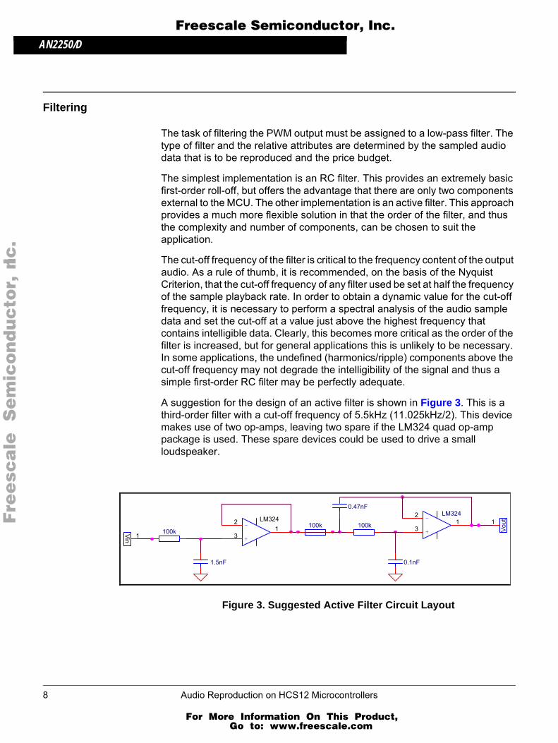
The cut-off frequency of the filter is critical to the frequency content of the output audio. As a rule of thumb, it is recommended, on the basis of the Nyquist Criterion, that the cut-off frequency of any filter used be set at half the frequency of the sample playback rate. In order to obtain a dynamic value for the cut-off frequency, it is necessary to perform a spectral analysis of the audio sample data and set the cut-off at a value just above the highest frequency that contains intelligible data. Clearly, this becomes more critical as the order of the filter is increased, but for general applications this is unlikely to be necessary. In some applications, the undefined (harmonics/ripple) components above the cut-off frequency may not degrade the intelligibility of the signal and thus a simple first-order RC filter may be perfectly adequate.
A suggestion for the design of an active filter is shown in Figure 3. This is a third-order filter with a cut-off frequency of 5.5kHz (11.025kHz/2). This device makes use of two op-amps, leaving two spare if the LM324 quad op-amp package is used. These spare devices could be used to drive a small loudspeaker.
Figure 3. Suggested Active Filter Circuit Layout
1
-
+
LM324
3
21
Vou
t1
Vin
100k
0.1nF
LM324100k
1.5nF
100k-
+3
21
0.47nF
8 Audio Reproduction on HCS12 Microcontrollers
For More Information On This Product, Go to: www.freescale.com
AN2250/DAmplification and Loudspeakers
F
ree
sca
le S
em
ico
nd
uc
tor,
I
Freescale Semiconductor, Inc.n
c..
.
Figure 4 shows the fast Fourier transforms of a speech sample played through a first-order passive and a third order active filter of equal cut-off frequency. The upper frequency components are clearly visible in the passive transform, while these are suppressed in the active example. These components give the passively filtered sample a tinny sound, while the active filtered sample is much clearer. Both samples are perfectly intelligible.
Figure 4. Fast Fourier Transform of Speech Sample
Amplification and Loudspeakers
The signal obtained from either filter should be amplified and used to drive a loudspeaker. This circuitry will depend upon the target loudspeaker, but it may be possible, design depending, to integrate op-amps used in active filtering with op-amps used to drive the loudspeaker on one IC, minimising the external component count.
It is possible to drive a small loudspeaker directly from the port pin with the series introduction of a strategically chosen capacitor. The loudspeaker will provide the resistive component of the RC filter, reducing external components to an absolute minimum. Extreme care should be taken not to overload the MCU, as damage will result if too much current is drawn from the port pin. Consult the data book for the device in question.
(a) Passive Filter (b) Active Filter
Audio Reproduction on HCS12 Microcontrollers 9
For More Information On This Product, Go to: www.freescale.com
AN2250/D
F
ree
sca
le S
em
ico
nd
uc
tor,
I
Freescale Semiconductor, Inc.n
c..
.
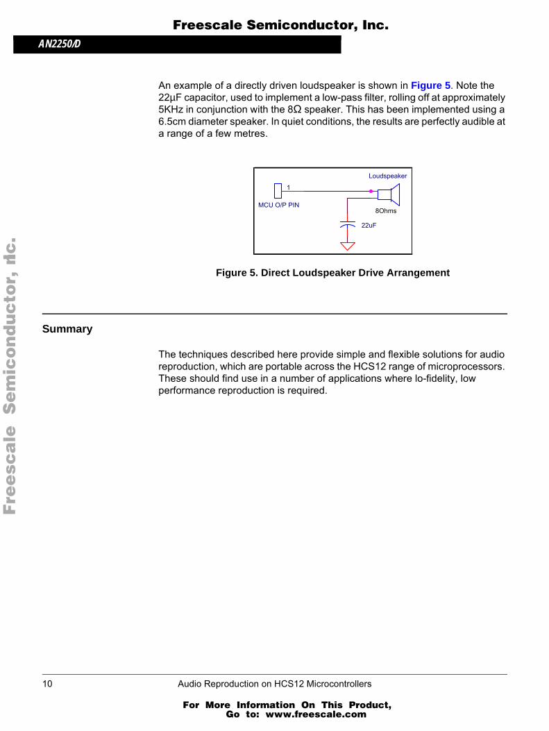
An example of a directly driven loudspeaker is shown in Figure 5. Note the 22µF capacitor, used to implement a low-pass filter, rolling off at approximately 5KHz in conjunction with the 8Ω speaker. This has been implemented using a 6.5cm diameter speaker. In quiet conditions, the results are perfectly audible at a range of a few metres.
Figure 5. Direct Loudspeaker Drive Arrangement
Summary
The techniques described here provide simple and flexible solutions for audio reproduction, which are portable across the HCS12 range of microprocessors. These should find use in a number of applications where lo-fidelity, low performance reproduction is required.
8Ohms
Loudspeaker
22uF
MCU O/P PIN
1
10 Audio Reproduction on HCS12 Microcontrollers
For More Information On This Product, Go to: www.freescale.com
AN2250/DUsing the Source Code Examples
F
ree
sca
le S
em
ico
nd
uc
tor,
I
Freescale Semiconductor, Inc.n
c..
.
Using the Source Code Examples
Three examples of source code are available from the Freescale web site. They are:
generatedsounds.c The name of this file on the Freescale web site is AN2250SW1.zip.
This is a stand-alone beep creator program that has been configured to play three different noises demonstrating the algorithmic reproduction capabilities of the HCS12 without the use of stored sample data. The three samples are a periodic beep, a periodic beep with a fade effect, and a warning whoop sound.
arraycreator.c The name of this file on the Freescale web site is AN2250SW2.zip.
This is the source code for the arraycreator.exe executable program. This takes a .WAV file called input.wav and produces a number of C files called outputxx.c
pwmcontroller.c The name of this file on the Freescale web site is AN2250SW3.zip.
This is the master program that takes the C files made by the arraycreator.exe program, stores them in the Flash memory, and implements the playback facility.
Audio Reproduction on HCS12 Microcontrollers 11
For More Information On This Product, Go to: www.freescale.com