23
1 ECE 3120 Microelectronics II Dr. Suketu Naik Chapter 9 Frequency Response PART C: High Frequency Response

1
ECE 3120 Microelectronics II Dr. Suketu Naik
Chapter 9
Frequency Response
PART C:
High Frequency
Response

2
ECE 3120 Microelectronics II Dr. Suketu Naik
Discrete Common Source (CS) Amplifier
Goal: find high cut-off frequency, fH
fH is dependent on
internal capacitances
Vo
Load Resistance
will affect fH

3
ECE 3120 Microelectronics II Dr. Suketu Naik
9.5.1 High Frequency Model of CS Amplifier
Goal: find high cut-off frequency, fH

4
ECE 3120 Microelectronics II Dr. Suketu Naik
Miller Effect or Miller Multiplier K
Impedance Z can be replaced with two impedances:
Z1 connected between node 1 and ground = Z/(1-K)
Z2 connected between node 2 and ground = Z/(1-1/K)

5
ECE 3120 Microelectronics II Dr. Suketu Naik
High-frequency model
C1 = Cgd(1-K), C2 = Cgd(1-1/K)
K =small signal gain= V0/Vgs=1+gmRL’; RL’=ro||RD||RL
Vo
Vo
Miller
Effect
Miller Effect or Miller Multiplier K
𝑹𝒔𝒊𝒈′=Rsig||RG
𝑹𝑳′ = 𝒓𝒐| 𝑹𝑫 |𝑹𝑳
input
resistance output
resistance

6
ECE 3120 Microelectronics II Dr. Suketu Naik
Estimating fH
𝑹𝒔𝒊𝒈′ = 𝑹𝒔𝒊𝒈||𝑹𝑮
𝑪𝒊𝒏 = 𝑪𝒈𝒔+ 𝑪𝟏𝑪𝟏 = 𝑪𝒈𝒅 𝟏 + 𝒈𝒎𝑹𝑳
′
𝑹𝑳′ = 𝒓𝒐| 𝑹𝑫 |𝑹𝑳
𝑨𝑴 = −𝑹𝑮
𝑹𝑮 + 𝑹𝒔𝒊𝒈𝒈𝒎𝑹𝑳
′
AM
fH: First Estimate (Miller’s Approximation)
Miller Effect
𝒇𝑯 =𝟏
𝟐𝝅𝑪𝒊𝒏𝑹𝒔𝒊𝒈′
Mid-band Gain
7
ECE 3120 Microelectronics II Dr. Suketu Naik
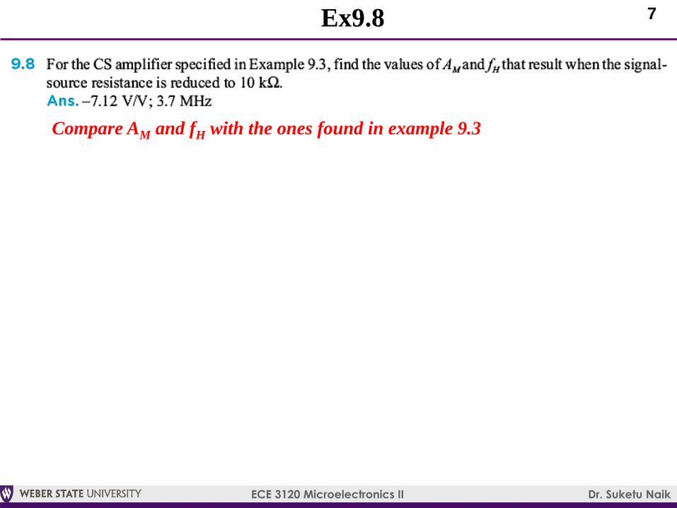
Ex9.8
Compare AM and fH with the ones found in example 9.3

8
ECE 3120 Microelectronics II Dr. Suketu Naik
9.5.2 Analysis Using Miller’s Theorem
High-frequency model with Load Capacitance CL
What is Load
Capacitance?

9
ECE 3120 Microelectronics II Dr. Suketu Naik
Estimating fH
AM
fH: Second Estimate (Miller’s Theorem)
𝒇𝑯 =𝟏
𝟏𝒇𝒑𝒊𝒏
𝟐+𝟏
𝒇𝒑𝒐𝒖𝒕𝟐
𝟏/𝟐
𝒇𝒑𝒊𝒏 =𝟏
𝟐𝝅𝑪𝒊𝒏𝑹𝒔𝒊𝒈′𝒇𝒑𝒐𝒖𝒕 =
𝟏
𝟐𝝅𝑪𝑳′𝑹𝑳′
𝑹𝒔𝒊𝒈′ = 𝑹𝒔𝒊𝒈||𝑹𝑮
𝑪𝒊𝒏 = 𝑪𝒈𝒔+ 𝑪𝒈𝒅 𝟏 + 𝒈𝒎𝑹𝑳′
𝑹𝑳′ = 𝒓𝒐| 𝑹𝑫 |𝑹𝑳
𝑪𝑳′ = 𝑪𝑳+ 𝑪𝒈𝒅 𝟏 + 𝟏/(𝒈𝒎𝑹𝑳′ )
C1 C2

10
ECE 3120 Microelectronics II Dr. Suketu Naik
Example 9.5
Transfer function
First approximation
Second
approximation
Exact Value
-3 dB frequency
= 9537 rad/s

11
ECE 3120 Microelectronics II Dr. Suketu Naik
Estimating fH
AM
fH: Third Estimate (Open Circuit Time Constants)

12
ECE 3120 Microelectronics II Dr. Suketu Naik
P9.60, P9.61: CS Amp
Omit the % contribution. Just calculate fH

13
ECE 3120 Microelectronics II Dr. Suketu Naik
Discrete Common Emitter (CE) Amplifier
Vo
Goal: find high cut-off frequency, fH
fH is dependent on
internal capacitances
Load Resistance
will affect fH

14
ECE 3120 Microelectronics II Dr. Suketu Naik
High Frequency Model of CE Amplifier
Goal: find high cut-off frequency, fH

15
ECE 3120 Microelectronics II Dr. Suketu Naik
High-frequency model
Vo
Miller Effect or Miller Multiplier K
𝑹𝒔𝒊𝒈′=Rsig||RG
𝑹𝑳′ = 𝒓𝒐| 𝑹𝑪 |𝑹𝑳
input
resistance output
resistance
C1 C2
16
ECE 3120 Microelectronics II Dr. Suketu Naik
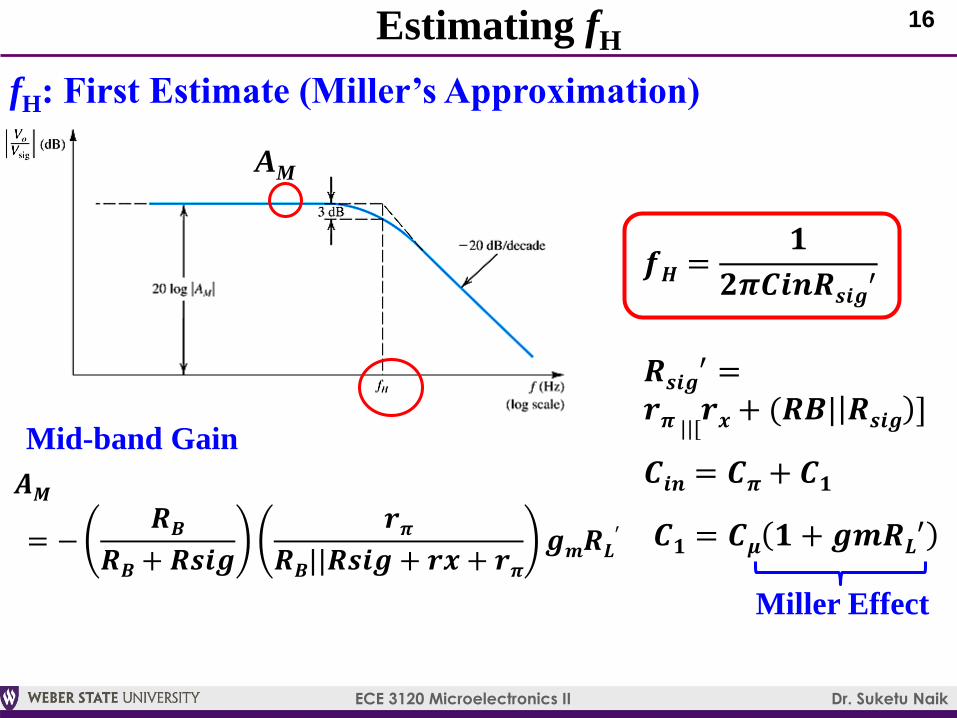
Estimating fH
𝑨𝑴
= −𝑹𝑩
𝑹𝑩+ 𝑹𝒔𝒊𝒈
𝒓𝝅𝑹𝑩||𝑹𝒔𝒊𝒈 + 𝒓𝒙 + 𝒓𝝅
𝒈𝒎𝑹𝑳′
AM
fH: First Estimate (Miller’s Approximation)
Miller Effect
𝒇𝑯 =𝟏
𝟐𝝅𝑪𝒊𝒏𝑹𝒔𝒊𝒈′
Mid-band Gain
𝑹𝒔𝒊𝒈′ =
𝒓𝝅 ||[𝒓𝒙+ (𝑹𝑩| 𝑹𝒔𝒊𝒈 ]
𝑪𝒊𝒏 = 𝑪𝝅+ 𝑪𝟏
𝑪𝟏 = 𝑪𝝁 𝟏 + 𝒈𝒎𝑹𝑳′

17
ECE 3120 Microelectronics II Dr. Suketu Naik
Ex9.10
Note the trade-off between gain and bandwidth
18
ECE 3120 Microelectronics II Dr. Suketu Naik
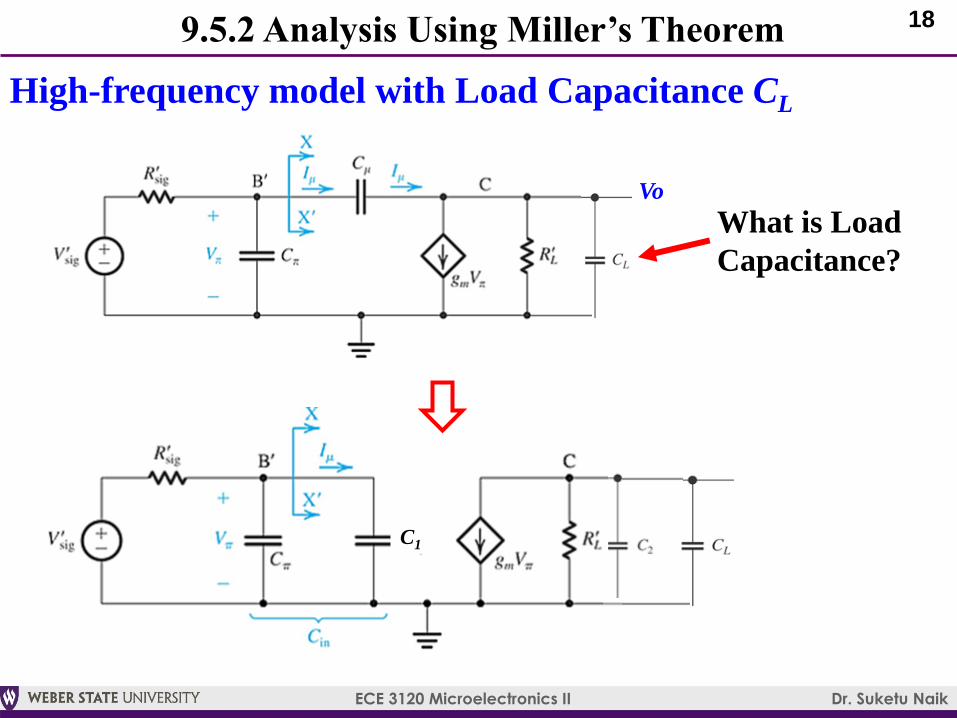
9.5.2 Analysis Using Miller’s Theorem
High-frequency model with Load Capacitance CL
What is Load
Capacitance?
Vo
C1
19
ECE 3120 Microelectronics II Dr. Suketu Naik
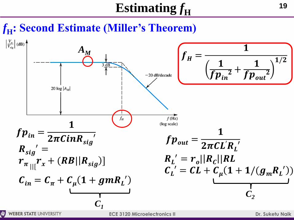
Estimating fH
AM
fH: Second Estimate (Miller’s Theorem)
𝒇𝑯 =𝟏
𝟏𝒇𝒑𝒊𝒏
𝟐+𝟏
𝒇𝒑𝒐𝒖𝒕𝟐
𝟏/𝟐
𝒇𝒑𝒊𝒏 =𝟏
𝟐𝝅𝑪𝒊𝒏𝑹𝒔𝒊𝒈′ 𝒇𝒑𝒐𝒖𝒕 =𝟏
𝟐𝝅𝑪𝑳′𝑹𝑳′
𝑹𝑳′ = 𝒓𝒐| 𝑹𝑪 |𝑹𝑳
𝑪𝑳′ = 𝑪𝑳 + 𝑪𝝁 𝟏 + 𝟏/(𝒈𝒎𝑹𝑳′ )
C1
C2
𝑹𝒔𝒊𝒈′ =
𝒓𝝅 ||[𝒓𝒙+ (𝑹𝑩| 𝑹𝒔𝒊𝒈 ]
𝑪𝒊𝒏 = 𝑪𝝅+ 𝑪𝝁 𝟏 + 𝒈𝒎𝑹𝑳′

20
ECE 3120 Microelectronics II Dr. Suketu Naik
Estimating fH
AM
fH: Third Estimate (Open Circuit Time Constants)

21
ECE 3120 Microelectronics II Dr. Suketu Naik
P9.64, 9.65: CE Amp
Omit the % contribution. Just calculate fH

22
ECE 3120 Microelectronics II Dr. Suketu Naik
Summary
Low Frequency Response:
The coupling and bypass capacitors cause the amplifier gain
to fall off at low frequencies
The low cut-off frequency can be estimated by considering
each of these capacitors separately
High Frequency Model:
Both MOSFET and the BJT have internal capacitive effects
that can be modeled by augmenting the device hybrid-π
model with capacitances.
Transition Frequency indicates the speed of the transistor
MOSFET: fT = gm/2π(Cgs+Cgd)
BJT: fT = gm/2π(Cπ+Cμ)
23
ECE 3120 Microelectronics II Dr. Suketu Naik
A figure-of-merit for the amplifier is the gain-bandwidth product
(GB = AMfH): tradeoff between gain and bandwidth while
keeping GB
High Frequency Response:
The internal capacitances of the MOSFET and the BJT cause the
amplifier gain to fall off at high frequencies.
An estimate of the amplifier bandwidth is provided by the
frequency fH at which the gain drops 3dB below its value at mid-
band (AM).
The high-frequency response of the CS and CE amplifiers is
severely limited by the Miller effect
Three methods: 1) Miller’s Approximation, 2) Miller’s Theorem,
3) Open-circuit Time Constants
Summary


