14
Embedded System, EE500, Dept. of Electrical Engineering, University at Buffalo Final Project Report Haowei Jiang 5016 6365 Fei Wei 5016 4316 12/7/2015
| Date post: | 18-Feb-2017 |
| Category: |
Documents |
| Upload: | haowei-jiang |
| View: | 151 times |
| Download: | 0 times |

Embedded System, EE500, Dept. of Electrical
Engineering, University at Buffalo
Final Project Report
Haowei Jiang
5016 6365
Fei Wei
5016 4316
12/7/2015
Introduction
Nowadays, Embedded system is playing a more and more significant rule in modern world,
with its small size, low cost, low power and high speed, it can be utilized in many different
scenarios. For example, the lab works we finished in this semester, the labs showed that
embedded systems can control the LCD, transmit data to other chips or computers via CAN
and UART buses, it can be scheduled with the timer interrupts and can make commands to
the Microcontroller by the out-interrupts.
As described before, we have done several implements in lab and got really interested in
embedded system, especially the microcontroller LPC1768. One of the most important
implement of embedded system is digital signal processing, that is why we would like to make
program to realize some basic digital signal processing algorithm on the LPC1768 develop
board like Fast Fourier Transformation. After the calculation we planned to display the FFT
spectrum on the LCD and refresh it periodically.
In this report, it presents a program to play real-time music through loudspeaker whose
signal transmitted via USB connection and shows the FFT spectrum of that period of music, in
which the sample rate is 32KHz and the FFT array length is about forty. The reason we choose
this number is that the LCD is 240*360, we choose to display the spectrum horizontally, so the
width is only 240 and the width of every column is 6, so the points could not be larger than 40.
And the half of FFT result is useless cause the result larger than Nyquist frequency is merely
copy of the spectrum before that. Using the Reader Algorithms on LCD board. It shows that
the music playing and display functions play well but not that perfectly. And in the discussion
chapter we will talk about the problems in detail and analysis the reason.
Solution
Here are some basic design ideas implemented in our final project and we will discuss them
in detail. Roughly there are four parts in our project named Initialization, Play Music, Fast Fourier
Transform Algorithm and LCD display respectively. And the peripherals we used in the experiment
are GPIO, Timer0, Timer1, GLCD, USB connection, LED.and related interrupts.
Initialization
Initializing is the very first step in every program. The chip resources will be use in the program
are Timer0, Timer1, AD Converter, DA Converter and USB. So we need to initialize all the resources.
SystemInit() could initialized the system clock, GLCD_Init() initialized LCD screen, USB_Init()
initialize the USB, after that we need to set the registers of LPC_PINCON, LPC_GPOI2, LPC_SC,
LPC_DAC and LPC_ADC. We need to initialize some other parts which we would use in our design.
Use a switch sentence where the PCLK is used to match the system frequency. Typically, the PCLK
for all the peripherals is 1/4 of the System Frequency (32 kHz), which is 8 kHz. That is the
initialization of the program.

Play Music
The function of play music is mainly contained in Timer0 Service Function.
As described before, we initialize the system clock by calling function SystemInit(), since that
we could use the ADC peripheral and Timers. Then we initialize and enable the Timer0 with
function NVIC_EnableIRQ(TIMER0_IRQn). When the timer counter matches to the number we set,
the system goes into interrupt. In the interrupt service function TIMER0_IRQHandler(void), the
process flow is: 1. Check the value of DataRun, if it is 1 which means there is data for receive the
value is read to val from DataBuf[DataOut] , if the sound is not mute, 10 bits of the value will be
write into LPC_DAC->DACR, which is a register connected to the Loud Speaker. And after the
process, LPC_TIM0->IR which is the interrupt register will be set to 1, which means it will be ready
to process next interrupt form Timer0.
Fast Fourier Transform Algorithm
We defined a struct which represent a complex (since the music signal is a serial of data).
Based on the definition of the struct we defined a struct array as input and output (after FFT, we
get complex value) and we apply the look-up table method to create a sin and cos value table
sin_tab() & cos_tab() instead of time-consuming direct calculation, this could improve the overall
operating speed.
In FFT, each point (usually N=2n) contains its frequency and Amplitude information. If the
Amplitude in Signal is A, then amplitude in FFT points is 2*A/N, except the 1st point – Direct Current
component, that is A/N. At the #n point, its frequency should be (n-1)*Fs/N where Fs is the
sampling frequency. Typically, the Fs in wav. File music is 44 kHz. Consider the resolution, if
Fs=1024Hz, N=1024, we get 1 Hz resolution = Fs/N. What’s more, with the symmetric property of
FFT, we only need to plot the half part of the calculation.
After that, we use the Reader algorithms, assuming the FFT number is N:
Firstly, we do the indexed calculation, to reverse the sequence of the natural sequence
Secondly, calculate the numbers of butterfly level m, total is log2N and distance between each
unit.
Then, by using double for-loop to calculate butterfly unit with both same and different
coefficients then apply the formula and do the next unit until the end of the loop.
Last, store the result in s[i] (complex struct array).
LCD Display
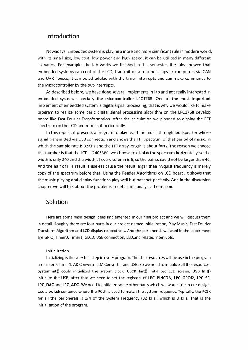
Totally we have three functions worked in our program, named display_0(), display_1() and
display_2() respectively. And when the user presses the button INT0, the display will change by a
switch-case function.
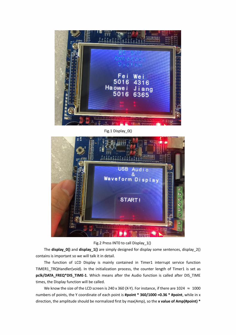
Fig.1 Display_0()
Fig.2 Press INT0 to call Display_1()
The display_0() and display_1() are simply designed for display some sentences, display_2()
contains is important so we will talk it in detail.
The function of LCD Display is mainly contained in Timer1 interrupt service function
TIMER1_TRQHandler(void). In the initialization process, the counter length of Timer1 is set as
pclk/DATA_FREQ*DIS_TIME-1. Which means after the Audio function is called after DIS_TIME
times, the Display function will be called.
We know the size of the LCD screen is 240 x 360 (X-Y). For instance, if there are 1024 ≈ 1000
numbers of points, the Y coordinate of each point is #point * 360/1000 =0.36 * #point, while in x
direction, the amplitude should be normalized first by max(Amp), so the x value of Amp(#point) *
240/ max(Amp).
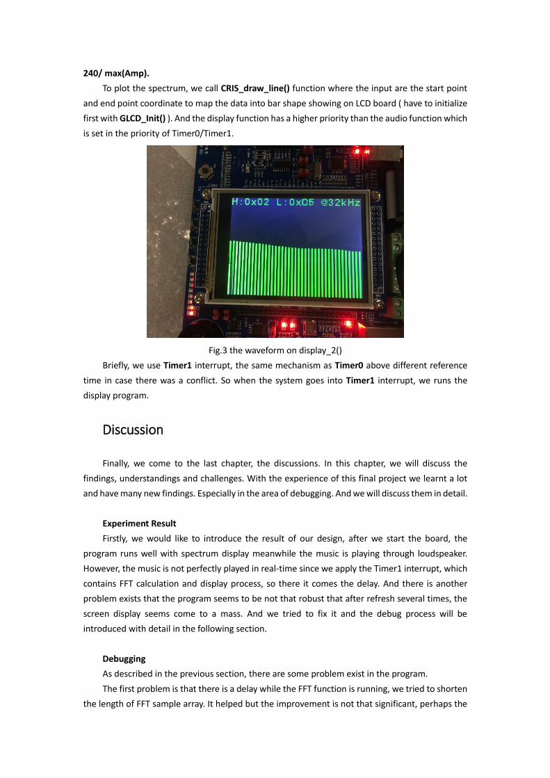
To plot the spectrum, we call CRIS_draw_line() function where the input are the start point
and end point coordinate to map the data into bar shape showing on LCD board ( have to initialize
first with GLCD_Init() ). And the display function has a higher priority than the audio function which
is set in the priority of Timer0/Timer1.
Fig.3 the waveform on display_2()
Briefly, we use Timer1 interrupt, the same mechanism as Timer0 above different reference
time in case there was a conflict. So when the system goes into Timer1 interrupt, we runs the
display program.
Discussion
Finally, we come to the last chapter, the discussions. In this chapter, we will discuss the
findings, understandings and challenges. With the experience of this final project we learnt a lot
and have many new findings. Especially in the area of debugging. And we will discuss them in detail.
Experiment Result
Firstly, we would like to introduce the result of our design, after we start the board, the
program runs well with spectrum display meanwhile the music is playing through loudspeaker.
However, the music is not perfectly played in real-time since we apply the Timer1 interrupt, which
contains FFT calculation and display process, so there it comes the delay. And there is another
problem exists that the program seems to be not that robust that after refresh several times, the
screen display seems come to a mass. And we tried to fix it and the debug process will be
introduced with detail in the following section.
Debugging
As described in the previous section, there are some problem exist in the program.
The first problem is that there is a delay while the FFT function is running, we tried to shorten
the length of FFT sample array. It helped but the improvement is not that significant, perhaps the

bottleneck is the calculation speed of the LPC1768 microcontroller.
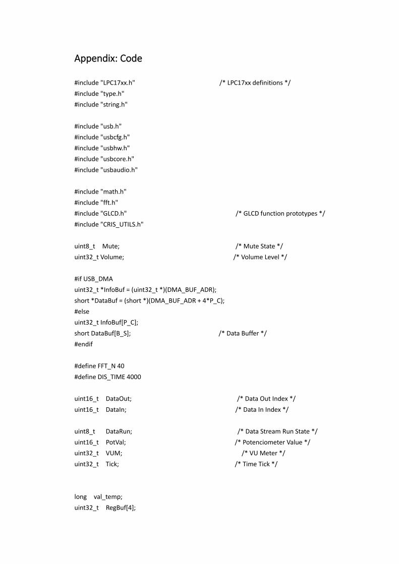
Fig.4 disordered display on LCD
The second problem we faced is the program disorder. Every time when we start the board,
the program can work well for only couple of seconds, and after the LCD screen refreshed several
times, the display on LCD disordered. For solve this problem, we tried to find some solutions.
At first, we thought maybe two Timers may interference with each other, so we changed the
priority of two timers, but it did not work. Also, we tried to use only one timer, but not only the
problem still existed, there seems to be a delay that the sound was lost.
Then, we thought maybe the display function would come disordered when be called in the
function, so we modified the program and add the display codes directly into the Timer1 interrupt
function, however, it did not work either.
We also modified the program to let there be a while loop in the main function, and set a
variable as counter to display, while it is displaying the Timer0 interrupt and sample the audio signal
from USB. But we failed again.
After that we want to find out what cause such a result. So we dug deep in the codes, and
found that may be the register of LPC_GPIO0 disordered. Usually, when the interrupt is called all
the registers values should be saved in stack. But it seems that there were some conflicts. We tried
to save the value of GPIO registers manually, but it still did not work. But we want to emphasize
that once I set a value in GPIO register randomly, the display on screen would disorder at once.
After try all these methods, the imperfection of the program exists. Optimization: To gain a better
resolution, we could increase the FFT number at the cost of delay time.
Conclusion
Finally, although we cannot claim that our project is perfectly done, during debugging we got
a deeper understanding about the resources of embedded system, for example, the USB
connection, Inner interrupt, Timer/Counter, and the display on LCD. With the experience of

implement digital signal processing on microcontroller, we realized how important the processing
speed is. And the essentiality to find the balance between cost and performance. Once we want to
implement some more complexed algorithm, we need more calculation capacity. When we were
trying to find what cause the disorder of LCD, we read some very basic level system library functions
which could directly set the values of some registers, which helped us a lot to understand the
operating process in embedded systems. Overall, we learned a lot in the final project.
And thanks to Professor Praveen Meduri and the TAs, Rajarshi Basak, Zahed Hossain and
Xuejuan Yang.
Appendix: Code
#include "LPC17xx.h" /* LPC17xx definitions */
#include "type.h"
#include "string.h"
#include "usb.h"
#include "usbcfg.h"
#include "usbhw.h"
#include "usbcore.h"
#include "usbaudio.h"
#include "math.h"
#include "fft.h"
#include "GLCD.h" /* GLCD function prototypes */
#include "CRIS_UTILS.h"
uint8_t Mute; /* Mute State */
uint32_t Volume; /* Volume Level */
#if USB_DMA
uint32_t *InfoBuf = (uint32_t *)(DMA_BUF_ADR);
short *DataBuf = (short *)(DMA_BUF_ADR + 4*P_C);
#else
uint32_t InfoBuf[P_C];
short DataBuf[B_S]; /* Data Buffer */
#endif
#define FFT_N 40
#define DIS_TIME 4000
uint16_t DataOut; /* Data Out Index */
uint16_t DataIn; /* Data In Index */
uint8_t DataRun; /* Data Stream Run State */
uint16_t PotVal; /* Potenciometer Value */
uint32_t VUM; /* VU Meter */
uint32_t Tick; /* Time Tick */
long val_temp;
uint32_t RegBuf[4];

uint16_t FFTcount; /* FFT count */
static uint16_t counter;
struct compx s[FFT_N]; /* FFT points */
static char valdisp[22];
char hex_chars[16] = {'0', '1', '2', '3', '4', '5', '6', '7', '8', '9', 'A', 'B', 'C', 'D', 'E', 'F'};
void display(void);
void Hex_Str (unsigned char hex, char *str);
/*
* Get Potenciometer Value
*/
void get_potval (void) {
uint32_t val;
LPC_ADC->ADCR |= 0x01000000; /* Start A/D Conversion */
do {
val = LPC_ADC->ADGDR; /* Read A/D Data Register */
} while ((val & 0x80000000) == 0); /* Wait for end of A/D Conversion */
LPC_ADC->ADCR &= ~0x01000000; /* Stop A/D Conversion */
PotVal = ((val >> 8) & 0xF8) + /* Extract Potenciometer Value */
((val >> 7) & 0x08);
}
/**************************************************************************
* Timer Counter 0 Interrupt Service Routine
* executed each 31.25us (32kHz frequency)
*************************************************************************/
void TIMER0_IRQHandler(void)
{
long val;
uint32_t cnt;
if (DataRun) { /* Data Stream is running */
val = DataBuf[DataOut]; /* Get Audio Sample */
cnt = (DataIn - DataOut) & (B_S - 1); /* Buffer Data Count */
if (cnt == (B_S - P_C*P_S)) { /* Too much Data in Buffer */
DataOut++; /* Skip one Sample */
}
if (cnt > (P_C*P_S)) { /* Still enough Data in Buffer */
DataOut++; /* Update Data Out Index */

}
DataOut &= B_S - 1; /* Adjust Buffer Out Index */
if (val < 0) VUM -= val; /* Accumulate Neg Value */
else VUM += val; /* Accumulate Pos Value */
val *= Volume; /* Apply Volume Level */
val >>= 16; /* Adjust Value */
val += 0x8000; /* Add Bias */
val &= 0xFFFF; /* Mask Value */
} else {
val = 0x8000; /* DAC Middle Point */
}
if (Mute) {
val = 0x8000; /* DAC Middle Point */
}
LPC_DAC->DACR = val & 0xFFC0; /* Set Speaker Output */
val_temp = val&0xffc0;
////////////////////////////////////////////////////////////////////////
if(FFTcount<FFT_N)
{
val_temp=val&0xFFC0;
val_temp=val_temp>>6;
strcpy(valdisp,"H: L: @32kHz");
Hex_Str((unsigned char)(val_temp&0x00ff), &valdisp[9]);
Hex_Str((unsigned char)(val_temp>>8), &valdisp[2]);
s[FFTcount].real= (float)(val_temp)/1024*240;
s[FFTcount].imag=0;
FFTcount++;
}
////////////////////////////////////////////////////////////////////////
if ((Tick++ & 0x03FF) == 0) { /* On every 1024th Tick */
get_potval(); /* Get Potenciometer Value */
if (VolCur == 0x8000) { /* Check for Minimum Level */
Volume = 0; /* No Sound */
} else {

Volume = VolCur * PotVal; /* Chained Volume Level */
}
val = VUM >> 20; /* Scale Accumulated Value */
VUM = 0; /* Clear VUM */
if (val > 7) val = 7; /* Limit Value */
}
counter++;
LPC_TIM0->IR = 1; /* Clear Interrupt Flag */
// NVIC_EnableIRQ(TIMER1_IRQn);
}
/**************************************************************************
***
* Timer Counter 1 Interrupt Service Routine
* executed each 31.25us (32kHz frequency)
***************************************************************************
***/
void TIMER1_IRQHandler(void)
{
int i;
//NVIC_DisableIRQ(TIMER0_IRQn);
GLCD_SetBackColor(Black);
GLCD_SetTextColor(Green);
GLCD_DisplayString(0, 0, " ");
GLCD_DisplayString(0, 0, (uint8_t*)valdisp);
FFT(s);
for(i=0;i<FFT_N;i++)
{
GLCD_SetTextColor(Black);
CRIS_draw_line(8*i, 239, 8*i , 19); //plot on LCD
CRIS_draw_line(8*i+1, 239, 8*i+1 , 19); //plot on LCD
CRIS_draw_line(8*i+2, 239, 8*i+2 , 19); //plot on LCD
GLCD_SetTextColor(Green);
CRIS_draw_line(8*i , 239, 8*i , 239-floor(s[i].real)); //plot on LCD
CRIS_draw_line(8*i+1, 239, 8*i+1 , 239-floor(s[i].real)); //plot on LCD
CRIS_draw_line(8*i+2, 239, 8*i+2 , 239-floor(s[i].real)); //plot on LCD
}
FFTcount=0;
counter=0;
LPC_TIM1->IR = 1;
//NVIC_EnableIRQ(TIMER0_IRQn);
}
/**************************************************************************
***
** Display Function display()
***************************************************************************
***/
void display()
{
int i;
GLCD_Clear(Black);
GLCD_SetBackColor(Black);
GLCD_SetTextColor(Green);
GLCD_DisplayString(0, 0, (uint8_t*)valdisp);
for(i=0;i<FFT_N;i++)
{
GLCD_SetTextColor(Green);
CRIS_draw_line(8*i, 239, 8*i , 239-floor(s[i].real)); //plot on LCD
CRIS_draw_line(8*i+7, 239, 8*i+7 , 239-floor(s[i].real)); //plot on LCD
CRIS_draw_line(8*i, 239-floor(s[i].real), 8*i+8 , 239-floor(s[i].real)); //plot on
LCD
GLCD_SetTextColor(Black);
CRIS_draw_line(8*i+1, 239, 8*i+6 , 239-floor(s[i].real)); //plot on LCD
}
}
/**************************************************************************
***
** Hex String Function Hex_Sr()
***************************************************************************
***/
void Hex_Str (unsigned char hex, char *str) {
*str++ = '0';
*str++ = 'x';
*str++ = hex_chars[hex >> 4];
*str++ = hex_chars[hex & 0xF];
}
/**************************************************************************
***
** Main Function main()
***************************************************************************
***/
int main (void)
{
volatile uint32_t pclkdiv, pclk;
SystemInit();
GLCD_Init();
GLCD_Clear(Black);
FFTcount=0;
counter=0;
LPC_PINCON->PINSEL1 &=~((0x03<<18)|(0x03<<20));
/* P0.25, A0.0, function 01, P0.26 AOUT, function 10 */
LPC_PINCON->PINSEL1 |= ((0x01<<18)|(0x02<<20));
LPC_GPIO2->FIODIR |= 1 << 0; /* P2.0 defined as Output (LED)
*/
LPC_PINCON->PINSEL3 |= (3ul<<30); /* P1.31 is AD0.5 */
LPC_SC->PCONP |= (1<<12); /* Enable power to ADC
block */
LPC_ADC->ADCR = (1<< 5) | /* select AD0.5 pin */
(4<< 8) | /* ADC clock is 25MHz/5 */
(1<<21); /* enable ADC */
/* Enable CLOCK into ADC controller */
// LPC_SC->PCONP |= (1 << 12);
// LPC_ADC->ADCR = 0x00200E04; /* ADC: 10-bit AIN2 @ 4MHz */
LPC_DAC->DACR = 0x00008000; /* DAC Output set to Middle Point */
/* By default, the PCLKSELx value is zero, thus, the PCLK for
all the peripherals is 1/4 of the SystemFrequency. */
/* Bit 2~3 is for TIMER0 */
pclkdiv = (LPC_SC->PCLKSEL0 >> 2) & 0x03;

switch ( pclkdiv )
{
case 0x00:
default:
pclk = SystemFrequency/4;
break;
case 0x01:
pclk = SystemFrequency;
break;
case 0x02:
pclk = SystemFrequency/2;
break;
case 0x03:
pclk = SystemFrequency/8;
break;
}
LPC_TIM0->MR0 = pclk/DATA_FREQ - 1; /* TC0 Match Value 0 */
LPC_TIM0->MCR = 3; /* TCO Interrupt and Reset on MR0 */
LPC_TIM0->TCR = 1; /* TC0 Enable */
NVIC_EnableIRQ(TIMER0_IRQn);
LPC_TIM1->MR0 = pclk/DATA_FREQ*DIS_TIME - 1; /* TC0 Match Value 0 */
LPC_TIM1->MCR = 3; /* TCO Interrupt and Reset on MR0 */
LPC_TIM1->TCR = 1; /* TC0 Enable */
NVIC_EnableIRQ(TIMER1_IRQn);
USB_Init(); /* USB Initialization */
USB_Connect(TRUE); /* USB Connect */
/********* The main Function is an endless loop ***********/
while( 1 );
}
/*************************************************************************
** End Of File
************************************************************************/


