University of Bologna Dottorato di Ricerca in Ingegneria Elettronica Informatica e delle Telecomunicazioni Short course on “RF electronics for wireless communication and remote sensing systems” Eleonora Franchi , Antonio Gnudi, Marco Guermandi DEIS-ARCES - University of Bologna Viale Risorgimento 2, Bologna, Italy Frequency synthesizers for RF transceivers University of Bologna Frequency synthesizers for RF transceivers q Introduction q Frequency synthesizer requirements for integrated RF transceivers q Phase locked-loops (PLL): architecture, and working principle and building blocks q PLL Modeling q Modeling of PLL in the frequency and time domain q Noise in PLLs q Design examples: 1) Synthesizer for UWB receivers (integer-N PLL) 2) Synthesizer and VCOs for fully-integrated reconfigurable multi- standard transceivers: • high tuning-range VCO • fractional-N synthesizers with techniques for spurious compensation and increased linearity.
Transcript
1
University of Bologna
Dottorato di Ricerca in Ingegneria Elettronica Informatica e delle Telecomunicazioni
Short course on
“RF electronics for wireless communication and remote sensing systems”
Eleonora Franchi, Antonio Gnudi, Marco Guermandi
DEIS-ARCES - University of Bologna
Viale Risorgimento 2, Bologna, Italy
Frequency synthesizers for RF transceivers
University of Bologna
Frequency synthesizers for RF transceivers
q Introductionq Frequency synthesizer requirements for integrated RF transceivers q Phase locked-loops (PLL): architecture, and working principle and building blocks
q PLL Modelingq Modeling of PLL in the frequency and time domainq Noise in PLLs
q Design examples: 1) Synthesizer for UWB receivers (integer-N PLL)2) Synthesizer and VCOs for fully-integrated reconfigurable multi-standard transceivers:
• high tuning-range VCO• fractional-N synthesizers with techniques for spurious compensation and increased linearity.
2
University of Bologna
Introduction
• Wireless and cellular standards require low-cost, low-power
• Sub-micron CMOS technologies achieve:– High transistor cut-off frequencies
– “Low cost” technologies
– VLSI for digital signal processing
RF front-end transceiver and the base band processor
can be realized on the same chip.
University of Bologna
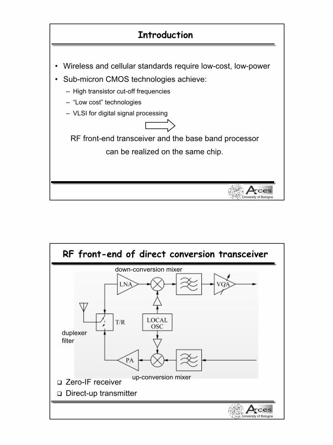
RF front-end of direct conversion transceiver
q Zero-IF receiverq Direct-up transmitter
down-conversion mixer
up-conversion mixer
duplexerfilter
3
University of Bologna
Frequency synthesizer requirements
• tuning range i.e. capability of synthesizing various RF frequencies according to the transceiver architecture and the communication system (channel spacing)
• frequency accuracy and stability in time and temperature
• spectral purity: phase noise and spurs
• switching time
University of Bologna
Phase Noise
• Due to the noise of the electronic circuits the oscillator outputs can be written as Vout = A(t) cos [ω0 t + φ(t)]
• Phase noise:
4
University of Bologna
Effect of phase-noise in a receiver
RF Input
Lo output
From RF Microlectronics Razavi, 1998, Fig. 7.13
Mixer
University of Bologna
Effect of spurs in a receiver
RF Input
Synt output
From RF Microlectronics Razavi, 1998, Fig. 8.2
Mixer
5
University of Bologna
Characteristics of some communication standards and phase noise requirements
• DECT – 10 channels spaced of 1.728 MHz from 1881 to 1897 MHz
– Settling time < 400 µs
– Phase Noise < -114 dBc/Hz @ 5.184MHz
• UWB MB-OFDM – Frequency range: 3432-to-10296 MHz.
– 14 center frequencies to be synthesized, spaced of 528 MHz
– Frequency switching time lower than 9.5 ns
– Accuracy 20 ppm
– Integrated Phase noise below 3.6o RMS
– Aggregate power of spurs lower than -24 dBc
University of Bologna
Characteristics of some communication standards and phase noise requirements
• UMTS RX
– Tuning range 60 MHz (2110 to 2170 MHz)
– channel spacing 5 MHz
– Phase Noise -130 dBc/Hz @1MHz
• E-GSM RX
– Tuning range 35 MHz (925 to 960 MHz)
– channel spacing 200 kHz
– Phase Noise -141 dBc/Hz @3MHz
• IEEE 802.11b (WLAN)
– Tuning range 84 MHz (2400 to 2483.5 MHz)
– Channel spacing 20 MHz
– Phase Noise -107 dBc/Hz @1MHz
6
University of Bologna
Integer-N PLL (Charge Pump Phase-Locked Loop)
• Phase Frequency Detector (PFD)
• Charge Pump (CP)
• Low Pass Filter (LPF)
• Voltage Controlled Oscillator (VCO)
• Frequency Divider (FD)
Icp Vc
University of Bologna
Voltage Controlled Oscillator (VCO)
LC oscillator •large area (integrated inductors)• fine tuning obtained by variable capacitor C = C(Vc) (varactor)• coarse tuning through array of switchable capacitors
LCfo π2
1=
N
C = Cfixed + Cprogrammable
7
University of Bologna
VCO Tuning Curves (DECT)
ω out = ωFR + KVCO VC KVCO = dω/dVc
1860 MHz
2060 MHz
University of Bologna
VCO Tuning Curves (multistandard transceiver)
KVCO = dω/dVcω out = ωFR + KVCO VC
8
University of Bologna
Frequency divider (FD)
FOUT FDIV = FOUT / NFD
N
Fout in the GHz rangeFref in the MHz range
N in the order of 102
• change in output frequency achieved by changing N