48
FRESH WATER PUMPING CATALOG Submersible Pump Protection • Single-Phase Pump Protection Three-Phase Pump Protection • Liquid Level Protection
| Date post: | 12-May-2018 |
| Category: |
Documents |
| Upload: | trannguyet |
| View: | 217 times |
| Download: | 0 times |

FRESH WATER PUMPINGCATALOG
Submersible Pump Protection • Single-Phase Pump Protection Three-Phase Pump Protection • Liquid Level Protection

Fault Damage
Equipment Replacement
Calibration Costs
Compliance Citations
Motor Rewinds
Shock Hazard
Injury to Personnel
Arc-Flash Hazards
Open-CT Hazards
Failed Resistors
Replacement Time
Nuisance Tripping
Intermittent Faults
Unreliable Protection
Calibration Time
CostSafety Downtime
Cover photo of pump (left) is courtesy of the Department of Water Resources
For All Types of Environments
Mining
Petrochemical, Oil and Gas
Power Generation
Pipelines and Transportation
Aggregate and Cement
Pulp and Paper
Water and Wastewater
Shore-to-Ship Power
Data Centers
Semiconductor Equipment
Hospitals
Alternative Energy
Manufacturing
We Improve Electrical Safety and Increase ProductivityThe Industrial Business Unit of Littelfuse delivers vital products to address customer needs for protection, safe control and distribution of electrical power in industrial applications. Our electrical safety product portfolio includes a comprehensive line of fuses, fuse holders, protection relays, and custom-engineered electrical products to minimize electrical safety hazards, limit equipment damage, improve productivity, and safeguard personnel from injury due to electrical faults.
Technically speaking, professionals in construction, manufacturing, mining, oil & gas, solar, and many more industries rely on Littelfuse for rugged, lasting protection for their designs.

© 2018 Littelfuse Fresh Water Pumping 1
Fresh Water Pumping
Littelfuse.com/Pump-Protection
TABLE OF CONTENTS
SUBMERSIBLE PUMPS - OPTIMIZED PROTECTION111-Insider-P / 231-Insider-P with Control Box ...........................................2 Single-Phase Pump Monitor
232-Insider with Grundfos® Control Box .......................................................5 Single-Phase Pump Monitor
234-P with Grundfos® Control Box ................................................................7 Single-Phase Pump Monitor
111P / 233P / 233P-1.5 .......................................................................................9 Single-Phase Pump Monitor
235P ....................................................................................................................11 Single-Phase Pump Monitor
Abbreviated Installation Instructions ..........................................................13
111P / 233P / 233P-1.5 / 235P in Enclosure .................................................15 Single-Phase Pump Monitor in a NEMA box
SINGLE-PHASE & THREE-PHASE PUMP PROTECTION MP8000 Series .................................................................................................16 Bluetooth® Overload Relay
SINGLE-PHASE PUMP PROTECTION 77C-KW/HP (2-800 Amps) ..............................................................................20 Programmable
77C-LR-KW/HP (1-9 Amps) ............................................................................20 Low-Range Programmable
THREE-PHASE PUMP PROTECTION 777-P2 Series ...................................................................................................25 Fully Programmable Electronic Overload Relay
777-KW/HP-P2 Series .....................................................................................27 Programmable Electronic Power Monitor
LIQUID LEVEL PROTECTION460-15-100-LLS .................................................................................................36 Liquid Level Sensor Relay (DIN-rail or surface mount)
PC-xxx-LLC-CZ / PC-xxx-LLC-GM Series ....................................................38 Liquid Level Control Relays (8-pin plug-in)
ACCESSORIESNEMA 3R-L Enclosure ....................................................................................42 Metal Electric Box
Informer ............................................................................................................43 Hand-Held Diagnostic Tool

© 2018 Littelfuse Fresh Water Pumping 2
Submersible Pumps – Optimized Protection Franklin™, CentriPro™, Pentek®, Grundfos® or Flint and Walling™ Control Box
111-INSIDER-P / 231-INSIDER-PSingle-Phase Pump Monitor
Littelfuse.com/Pump-Protection
DescriptionThe Littelfuse 111-Insider-P single-phase products fit inside ¹⁄³ and ½ hp, 115V control boxes and the 231-Insider-P fits inside ¹⁄³, ½, ¾, and 1 hp, 230V control boxes. Both models are designed to protect single-phase pumps from dry-well, dead-head, jammed impeller, rapid-cycle, overvoltage, and undervoltage conditions.
A calibration adjustment allows the Insider to be calibrated to your specific pumping applications, thereby reducing the possibility of false or nuisance tripping. A unique microcontroller-based voltage and current-sensing circuit constantly monitors the incoming power for fluctuations, overcurrent, and undercurrent. When an abnormality, such as loss of suction is detected, the product deactivates its output relay and directly disconnects the pump motor. The unit then begins its user-selectable restart delay (dry-well recovery) timer. When the timer counts to zero or power is removed and reapplied, the unit reactivates its output relay and turns the pump back on. By leaving the restart delay knob in the reset position, the unit will operate in manual reset mode.
The Insider communicates with a hand-held diagnostics tool called the Informer (sold separately). The Informer displays parameters including calibration points, trip points, run time and last faults. An IR Kit-12 (12” fiber optic kit) is included with each Insider, allowing the Informer to access these parameters even when the Insider is enclosed in a control box. This is valuable for troubleshooting the pump while it is running.
NOTE: The 111/231-Insider-P models have a sensitivity adjustment for the dry-well trip point. After calibration is done, you can adjust the sensitivity for the dry-well/dead-head trip point from 70-90% of the full load. This makes the unit even more adaptable to varying pumping applications. If you have a very low producing well, you increase the sensitivity closer to the 90% mark, or if you have a very heavy producing well, you would decrease the sensitivity around the 70% mark.
AccessoriesInformer A hand-held diagnostic tool that uses an infrared receiver to access information which can be helpful for troubleshooting the system.
Informer IR Kit-12Attaches to the face of the unit to provide remote diagnostics without opening the panel. (12” fiber optic cable)
MODEL VOLTAGE DESCRIPTION
111-Insider-P 115VAC ¹⁄³ - ½ hp, includes IR Kit-12
231-Insider-P 230VAC ¹⁄³ - 1 hp, includes IR Kit-12
Ordering Information
© 2018 Littelfuse Fresh Water Pumping 3
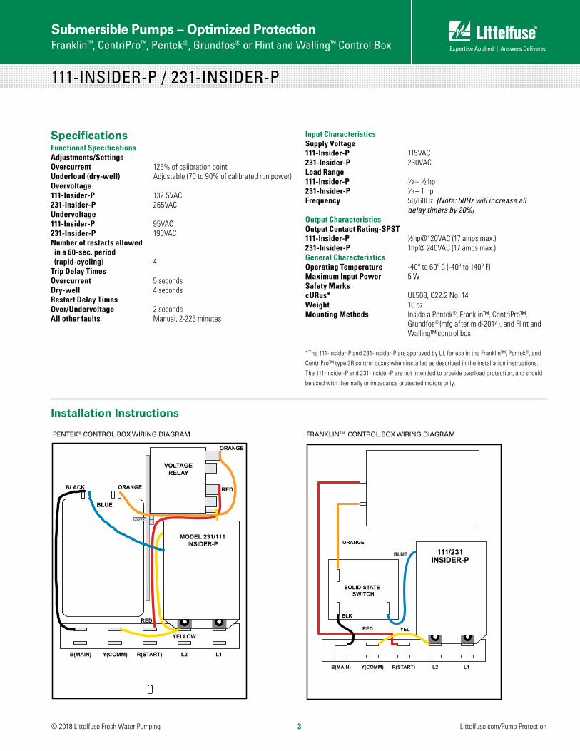
SpecificationsFunctional SpecificationsAdjustments/Settings Overcurrent 125% of calibration pointUnderload (dry-well) Adjustable (70 to 90% of calibrated run power)Overvoltage111-Insider-P 132.5VAC231-Insider-P 265VACUndervoltage 111-Insider-P 95VAC231-Insider-P 190VACNumber of restarts allowed in a 60-sec. period (rapid-cycling) 4 Trip Delay Times Overcurrent 5 secondsDry-well 4 secondsRestart Delay Times Over/Undervoltage 2 secondsAll other faults Manual, 2-225 minutes
Submersible Pumps – Optimized Protection Franklin™, CentriPro™, Pentek®, Grundfos® or Flint and Walling™ Control Box
111-INSIDER-P / 231-INSIDER-P
Littelfuse.com/Pump-Protection
MODEL 231/111INSIDER-P
BLUE
FIGURE 5: Pentek® Control Box with the PumpSaver®Plus Installed
PENTEK® CONTROL BOX WIRING DIAGRAM FRANKLIN™ CONTROL BOX WIRING DIAGRAM
111-Insider-P/231-Insider-P in Franklin™ Control Box
SOLID-STATE SWITCH
B(MAIN) Y(COMM)
BLK
RED
ORANGE
YEL
R(START) L2 L1
BLUE 111/231INSIDER-P
Installation Instructions
Input CharacteristicsSupply Voltage111-Insider-P 115VAC231-Insider-P 230VACLoad Range111-Insider-P ¹⁄ ³ – ½ hp231-Insider-P ¹⁄ ³ – 1 hpFrequency 50/60Hz (Note: 50Hz will increase all delay timers by 20%)Output CharacteristicsOutput Contact Rating-SPST111-Insider-P ½hp@120VAC (17 amps max.) 231-Insider-P 1hp@ 240VAC (17 amps max.)General CharacteristicsOperating Temperature -40º to 60º C (-40º to 140º F)Maximum Input Power 5 WSafety MarkscURus* UL508, C22.2 No. 14Weight 10 oz.Mounting Methods Inside a Pentek®, Franklin™, CentriPro™, Grundfos® (mfg after mid-2014), and Flint and Walling™ control box
*The 111-Insider-P and 231-Insider-P are approved by UL for use in the Franklin™, Pentek®, and CentriPro™ type 3R control boxes when installed as described in the installation instructions. The 111-Insider-P and 231-Insider-P are not intended to provide overload protection, and should be used with thermally or impedance protected motors only.

© 2018 Littelfuse Fresh Water Pumping 4
Submersible Pumps – Optimized Protection Franklin™, CentriPro™, Pentek®, Grundfos® or Flint and Walling™ Control Box
Littelfuse.com/Pump-Protection
111-INSIDER-P / 231-INSIDER-P
FLINT AND WALLING™ CONTROL BOX WIRING DIAGRAM
CAPACITORORANGE
BLUE
BLACK
5YELLOW
231/111 INSIDER-P
VOLTAGERELAY
1 2
YELLOW RED
B(MAIN) Y(COMM) R(START) L2 L1
FIGURE 9: Flint and Walling™ Control Box with the PumpSaver®Plus Installed
CENTRIPRO™ CONTROL BOX WIRING DIAGRAM
VOLTAGERELAY
B(MAIN) Y(COMM)
BLACK
ORANGE
R(START) L2 L1
BLUE
231/111INSIDER-P
YELLOW YELLOWRED
FIGURE 7: CentriPro™ Control Box with the PumpSaver®Plus Installed
GRUNDFOS® CONTROL BOX* WIRING DIAGRAM
Grundfos® Control Box with the PumpSaver®Plus Installed
CAPACITORORANGE
EBLU
BLACK
5
YELLOW
VOLTAGERELAY
1
2
YELLOW
RED
B(MAIN) Y(COMM) R(START) L2 L1
MODEL 231/111INSIDER-P
BLACK
* For boxes manufactured in mid 2014 or later. See 232-INSIDER page 6 for boxes manufactured prior to mid 2014.
© 2018 Littelfuse Fresh Water Pumping 5
Submersible Pumps – Optimized Protection Grundfos® Control Box
Littelfuse.com/Pump-Protection
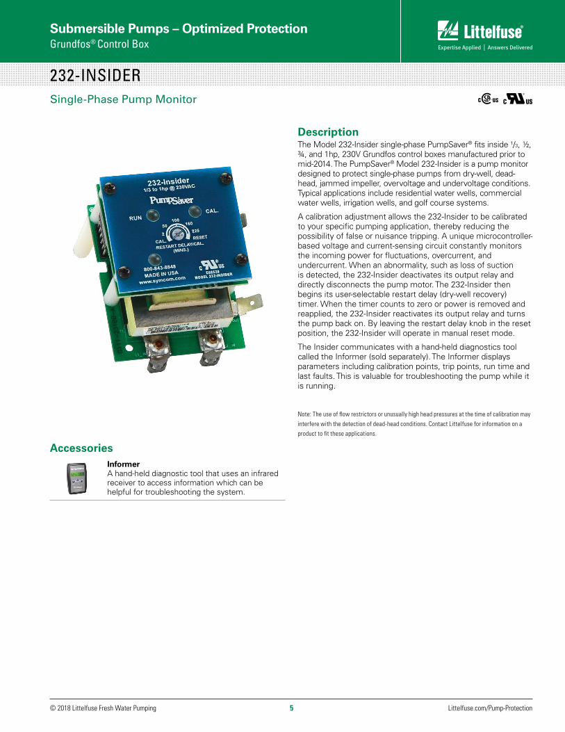
232-INSIDERSingle-Phase Pump Monitor
DescriptionThe Model 232-Insider single-phase PumpSaver® fits inside ¹/3, ½, ¾, and 1hp, 230V Grundfos control boxes manufactured prior to mid-2014. The PumpSaver® Model 232-Insider is a pump monitor designed to protect single-phase pumps from dry-well, dead-head, jammed impeller, overvoltage and undervoltage conditions. Typical applications include residential water wells, commercial water wells, irrigation wells, and golf course systems.
A calibration adjustment allows the 232-Insider to be calibrated to your specific pumping application, thereby reducing the possibility of false or nuisance tripping. A unique microcontroller-based voltage and current-sensing circuit constantly monitors the incoming power for fluctuations, overcurrent, and undercurrent. When an abnormality, such as loss of suction is detected, the 232-Insider deactivates its output relay and directly disconnects the pump motor. The 232-Insider then begins its user-selectable restart delay (dry-well recovery) timer. When the timer counts to zero or power is removed and reapplied, the 232-Insider reactivates its output relay and turns the pump back on. By leaving the restart delay knob in the reset position, the 232-Insider will operate in manual reset mode.
The Insider communicates with a hand-held diagnostics tool called the Informer (sold separately). The Informer displays parameters including calibration points, trip points, run time and last faults. This is valuable for troubleshooting the pump while it is running.
Note: The use of flow restrictors or unusually high head pressures at the time of calibration may interfere with the detection of dead-head conditions. Contact Littelfuse for information on a product to fit these applications.
AccessoriesInformer A hand-held diagnostic tool that uses an infrared receiver to access information which can be helpful for troubleshooting the system.
© 2018 Littelfuse Fresh Water Pumping 6Littelfuse.com/Pump-Protection
Submersible Pumps – Optimized Protection Grundfos® Control Box
232-INSIDER
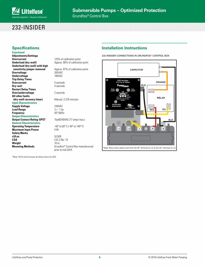
Installation Instructions
232-INSIDER CONNECTIONS IN GRUNDFOS® CONTROL BOX
SpecificationsFunctionalAdjustments/SettingsOvercurrent 125% of calibration pointUnderload (dry-well) Approx. 80% of calibration pointUnderload (dry well) with high sensitivity jumper removed Approx. 87% of calibration point Overvoltage 265VACUndervoltage 190VACTrip Delay TimesOvercurrent 5 secondsDry-well 4 secondsRestart Delay TimesOver/undervoltage 2 secondsAll other faults (dry-well recovery timer) Manual, 2-225 minutesInput CharacteristicsSupply Voltage 230VACLoad Range ¹⁄3 – 1 hpFrequency 50*/60Hz Output CharacteristicsOutput Contact Rating-SPST 1hp@240VAC (17 amps max.)General CharacteristicsOperating Temperature -40º to 60º C (-40º to 140º F)Maximum Input Power 5 WSafety MarkscULus UL508CSA C22.2 No. 14Weight 10 oz.Mounting Methods Grundfos® Control Box manufactured prior to mid-2014
*Note: 50 Hz will increase all delay timers by 20%
BLK
BLKORANGE
YEL
CAPACITOR
RED
YELYEL
RELAY
L1 L2 Y R B*
*Note: Move short yellow wire from the 90° terminal on L2 to the 45° terminal on L2.
232-Insider1/3 to 1hp @ 230VAC
RESTART DELAY/CAL.(MINS.)
800-843-8848MADE INUSA
E68520MODEL 232-INSIDER

© 2018 Littelfuse Fresh Water Pumping 7
Submersible Pumps – Optimized Protection Grundfos® Control Box
Littelfuse.com/Pump-Protection
234-P
Description The PumpSaver® Model 234-P is designed to be mounted inside a Grundfos® control box to protect ¹/3 – 3hp, 2- or 3-wire, 230V pumps.
The Model 234-P protects single-phase pumps from dry-well, dead-head, rapid-cycle, jammed-impeller, and over/undervoltage conditions. Typical applications include residential waterwells, commercial waterwells, irrigation wells, and golf course and other sprinkler systems.
A calibration adjustment allows the 234-P to be calibrated to your specific pumping applications, thereby reducing the possibility of false or nuisance tripping. A unique microcontroller-based voltage and current-sensing circuit constantly monitors the incoming power for fluctuations, overcurrent, and undercurrent. When an abnormality, such as loss of suction is detected, the 234-P deactivates its output relay and directly disconnects the pump motor. The 234-P then begins its user-selectable restart delay (dry-well recovery) timer. When the timer counts to zero or power is removed and reapplied, the 234-P reactivates its output relay and turns the pump back on. By leaving the restart delay knob in the reset position, the 234-P will operate in manual reset mode.
The 234-P communicates with a hand-held diagnostics tool called the Informer (sold separately). The Informer displays parameters including calibration points, trip points, run time and last faults. An IR Kit-12 (12” fiber optic kit) allows the Informer to access these parameters even when the 234-P is enclosed in a control box. This is valuable for troubleshooting the pump while it is running.
NOTE: The PumpSaver® models have a sensitivity adjustment for the dry-well trip point. After calibration is done, you can adjust the sensitivity for the dry-well/dead-head trip point from 70-90% of the full load. This makes the unit even more adaptable to varying pumping applications. If you have a very low producing well, you increase the sensitivity closer to the 90% mark, or if you have a very heavy producing well, you would decrease the sensitivity around the 70% mark.
The Model 234-P is not recommended for use with the Grundfos® Deluxe Control Box.
Single-Phase Pump Monitor
AccessoriesInformer A hand-held diagnostic tool that uses an infrared receiver to access information which can be helpful for troubleshooting the system. Includes the Informer IR Kit-12
Informer IR Kit-1212” infrared adapter cable attaches to the face of the unit to provide remote diagnostics without opening the panel. Included with the Informer

© 2018 Littelfuse Fresh Water Pumping 8
Submersible Pumps – Optimized Protection Grundfos® Control Box
Littelfuse.com/Pump-Protection
SpecificationsFunctional SpecificationsAdjustments/SettingsOvercurrent 125% of calibration pointUnderload (dry-well) Adjustable (70 - 90% of calibrated run power)Overvoltage 265VACUndervoltage 190VACNumber of restarts allowed in a 60-second period (rapid-cycling) 4Trip Delay Times Overcurrent 5 secondsDry-well 4 secondsRestart Delay Times Over/undervoltage 2 secondsAll other faults (dry-well recovery timer) Manual, 2-225 MinutesInput CharacteristicsSupply Voltage 230VACLoad Range ¹⁄3 – 3 hpFrequency 50*/60Hz Output CharacteristicsOutput Contact Rating (SPST) 3 hp @ 240VAC (17 amps max.)General CharacteristicsOperating Temperature -40º to 60º C (-40º to 140º F)Maximum Input Power 5WDimensions Fitted to Grundfos® Control BoxWeight 14 oz.Mounting Methods Grundfos® Control BoxStandards PassedElectrostatic Discharge (ESD) IEC 61000-4-2, Level 2, 4kV contact, 6kV air
*Note: 50 Hz will increase all delay timers by 20%
Installation Instructions
STARTCAPACITOR
RUNCAPACITOR
RELAY
YELLOW RED
ORANGE
BLACK
BLACK
BLK
BLUE
SW L1 L2 YEL RED BLK
RESTART DELAY/
1.5 to 3hp at 230VAC
_ +
IRLINK
YELLOW
234-P CONNECTIONS IN GRUNDFOS® CONTROL BOX
234-P

© 2018 Littelfuse Fresh Water Pumping 9
Submersible Pumps – Optimized Protection
Littelfuse.com/Pump-Protection
DescriptionThe Littelfuse Models 111P (115 volt, ¹⁄³ to 1hp); 233P-1.5 (230 volt, ¹⁄³ to 1.5hp); and 233P (230 volt, ¹⁄³ to 3hp) protect pumps from dry-well, dead-head, jammed impeller, overvoltage/undervoltage conditions, and rapid-cycle protection whether the pressure switch is mounted before or after our unit.
A calibration adjustment allows the unit to be calibrated to your specific pumping applications, thereby reducing the possibility of false or nuisance tripping. A unique microcontroller-based voltage and current-sensing circuit constantly monitors the incoming power for fluctuations, overcurrent, and undercurrent. When an abnormality, such as loss of suction is detected, the unit deactivates its output relay and directly disconnects the pump motor. The unit then begins its user-selectable restart delay (dry-well recovery) timer. When the timer counts to zero or power is removed and reapplied, the unit reactivates its output relay and turns the pump back on.
The infrared LED communicates with a hand-held diagnostics tool called the Informer (sold separately). The Informer displays parameters including calibration points, trip points, run time and last faults.
Special considerations for pump cables larger than #10 AWG: In some cases where larger motors are installed with deep set pumps, pump cables are used that exceed the relay’s terminal size. In these conditions, a short splice of #10 AWG or #12 AWG may be a solution at the control box. Note: All local, state and national electric codes should be followed when applying this solution.
NOTE: The 111P/233P/233P-1.5 models have a sensitivity adjustment for the dry-well trip point. After calibration is done, you can adjust the sensitivity for the dry-well/dead-head trip point from 70-90% of the full load. This makes the unit even more adaptable to varying pumping applications. If you have a very low producing well, you increase the sensitivity closer to the 90% mark, or if you have a very heavy producing well, you would decrease the sensitivity around the 70% mark.
AccessoriesInformer A hand-held diagnostic tool that uses an infrared receiver to access information which can be helpful for troubleshooting the system.
111P / 233P / 233P-1.5 Single-Phase Pump Monitor
MODEL LINE VOLTAGE DESCRIPTION
111P 115VAC ¹⁄³ - 1hp
233P 230VAC ¹⁄³ - 3hp
233P-1.5 230VAC ¹⁄³ - 1.5hp
Ordering Information

© 2018 Littelfuse Fresh Water Pumping 10
Submersible Pumps – Optimized Protection
Littelfuse.com/Pump-Protection
SpecificationsFunctional SpecificationsAdjustments/SettingsOvercurrent 125% of calibration pointUnderload (dry-well) Adjustable (70 to 90% of calibrated run power)Overvoltage111P 132.5VAC233P, 233P-1.5 265VACUndervoltage111P 95VAC233P, 233P-1.5 190VACNumber of restarts allowed in a 60-sec. period (rapid-cycling) 4Trip Delay Times Overcurrent 5 seconds Dry-well 4 secondsRestart Delay Times Over/undervoltage 2 seconds All other faults Manual, 2-225 Minutes Input CharacteristicsSupply Voltage111P 115VAC233P-1.5, 233P 230VACLoad Range:111P ¹⁄ ³ – 1 hp233P-1.5 ¹⁄ ³ – 1.5 hp233P ¹⁄ ³ – 3 hpFrequency 50*/60Hz Output CharacteristicsOutput Contact Rating-SPST111P 1hp@120VAC (16 amps max.)233P-1.5 1.5hp@240VAC (10 amps max.)233P 3hp@240VAC (17 amps max.)General CharacteristicsOperating Temperature -40º to 60º C (-40º to 140º F)Maximum Input Power 5 WWire Gauge Solid or Stranded 10 - 22AWGTerminal Torque 13 in.-lbs.Safety MarkscULus Listed UL508, C22.2 No. 14Dimensions H 73.66 mm (2.9”); W 133.35 mm (5.25”); D 73.99 mm (2.913”)Weight 14 oz.Mounting Methods #8 screws
*Note: 50Hz will increase all delay timers by 20%
Dimensions
111P / 233P / 235P DIMENSIONS
4.03" (102.36)
5.25" (133.35)
4.50" (114.30)
0.375" (9.53)
2.90"(73.66)
2.163"(54.94)
2.913"(73.99)
111P / 233P / 235P DIMENSIONS
4.03" (102.36)
5.25" (133.35)
4.50" (114.30)
0.375" (9.53)
2.90"(73.66)
2.163"(54.94)
2.913"(73.99)
111P / 233P / 233P-1.5
Installation Instructions
TYPICAL WIRING DIAGRAM FOR 111P / 233P / 233P-1.5
Models 111P / 233P
OPTIONAL PRESSURE SWITCH
OR CIRCUIT BREAKER
GND
L2
L1
111P / 233PMODEL
FUSED DISCONNECT
INL1 L1
OUT INL2
OUTL2
(IF USED)CONTROL BOX
3 WIRE
PRESSURE SWITCH
MOTORPUMP
LOCATION Shows Internal Connections
© 2018 Littelfuse Fresh Water Pumping 11
Submersible Pumps – Optimized Protection
Littelfuse.com/Pump-Protection
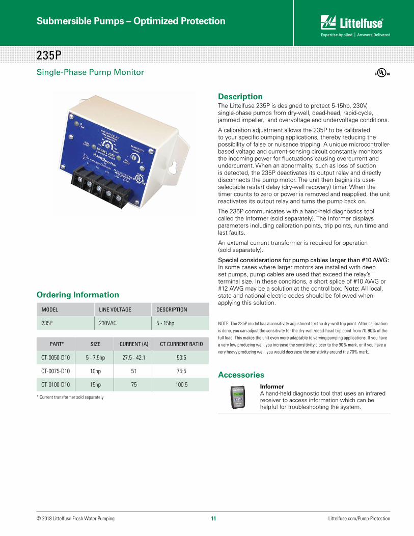
DescriptionThe Littelfuse 235P is designed to protect 5-15hp, 230V, single-phase pumps from dry-well, dead-head, rapid-cycle, jammed impeller, and overvoltage and undervoltage conditions.
A calibration adjustment allows the 235P to be calibrated to your specific pumping applications, thereby reducing the possibility of false or nuisance tripping. A unique microcontroller-based voltage and current-sensing circuit constantly monitors the incoming power for fluctuations causing overcurrent and undercurrent. When an abnormality, such as loss of suction is detected, the 235P deactivates its output relay and directly disconnects the pump motor. The unit then begins its user-selectable restart delay (dry-well recovery) timer. When the timer counts to zero or power is removed and reapplied, the unit reactivates its output relay and turns the pump back on.
The 235P communicates with a hand-held diagnostics tool called the Informer (sold separately). The Informer displays parameters including calibration points, trip points, run time and last faults.
An external current transformer is required for operation (sold separately).
Special considerations for pump cables larger than #10 AWG: In some cases where larger motors are installed with deep set pumps, pump cables are used that exceed the relay’s terminal size. In these conditions, a short splice of #10 AWG or #12 AWG may be a solution at the control box. Note: All local, state and national electric codes should be followed when applying this solution.
NOTE: The 235P model has a sensitivity adjustment for the dry-well trip point. After calibration is done, you can adjust the sensitivity for the dry-well/dead-head trip point from 70-90% of the full load. This makes the unit even more adaptable to varying pumping applications. If you have a very low producing well, you increase the sensitivity closer to the 90% mark, or if you have a very heavy producing well, you would decrease the sensitivity around the 70% mark.
AccessoriesInformer A hand-held diagnostic tool that uses an infrared receiver to access information which can be helpful for troubleshooting the system.
235PSingle-Phase Pump Monitor
MODEL LINE VOLTAGE DESCRIPTION
235P 230VAC 5 - 15hp
Ordering Information
PART* SIZE CURRENT (A) CT CURRENT RATIO
CT-0050-D10 5 - 7.5hp 27.5 - 42.1 50:5
CT-0075-D10 10hp 51 75:5
CT-0100-D10 15hp 75 100:5
* Current transformer sold separately

© 2018 Littelfuse Fresh Water Pumping 12
Submersible Pumps – Optimized Protection
Littelfuse.com/Pump-Protection
SpecificationsFunctional SpecificationsAdjustments/SettingsOvercurrent 125% of calibration pointUnderload (dry-well) Adjustable (70 to 90% of calibrated run power)Overvoltage 265VACUndervoltage 190VACNumber of restarts allowed in a 60-sec. period (rapid-cycling) 4Trip Delay Times Overcurrent 5 seconds Dry-well 4 secondsRestart Delay Times Over/undervoltage 2 seconds All other faults Manual, 2-225 MinutesInput CharacteristicsSupply Voltage 230VACLoad Range 5 - 15 hpFrequency 50*/60HzOutput CharacteristicsOutput Contact Rating-SPST A300, 720A @240VAC (10 amps max.)General CharacteristicsOperating Temperature -40º to 60º C (-40º to 140º F)Maximum Input Power 5 WWire Gauge Solid or Stranded 10 - 22AWGTerminal Torque 13 in.-lbs.Safety MarkscULus Listed UL508, C22.2 No. 14Dimensions H 73.66 mm (2.9”); W 133.35 mm (5.25”); D 73.99 mm (2.913”)Weight 14 oz.Mounting Methods #8 screws
*Note: 50Hz will increase all delay timers by 20%)
Dimensions
111P / 233P / 235P DIMENSIONS
4.03" (102.36)
5.25" (133.35)
4.50" (114.30)
0.375" (9.53)
2.90"(73.66)
2.163"(54.94)
2.913"(73.99)
111P / 233P / 235P DIMENSIONS
4.03" (102.36)
5.25" (133.35)
4.50" (114.30)
0.375" (9.53)
2.90"(73.66)
2.163"(54.94)
2.913"(73.99)
Installation Instructions
TYPICAL WIRING DIAGRAM FOR 235P
Model 235P
Shows Internal Connection
235P
© 2018 Littelfuse Fresh Water Pumping 13
Submersible Pumps – Optimized Protection
Littelfuse.com/Pump-Protection
ABBREVIATED INSTALLATION INSTRUCTIONS
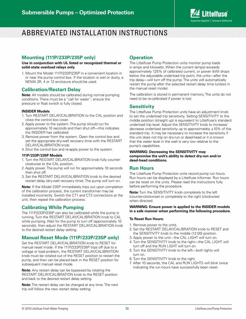
OperationThe Littelfuse Pump Protection units monitor pump loads in amps and kilowatts. When the current (amps) exceeds approximately 125% of calibrated current, or power (kW) drops below the adjustable underload trip point, the units—after the trip delay—will turn off the pump. The units will automatically restart the pump after the selected restart delay time (unless in the manual reset mode).
The calibration is stored in permanent memory. The units do not need to be re-calibrated if power is lost.
SensitivityThe Littelfuse Pump Protection units have an adjustment knob to set the underload trip sensitivity. Setting SENSITIVITY to the middle position (straight up) is equivalent to Littelfuse’s standard underload trip level. Adjust the SENSITIVITY knob to increase/decrease underload sensitivity up to approximately ±10% of the standard trip. It may be necessary to increase the sensitivity if the unit does not trip on dry-run or dead-head or it is known that the water level in the well is very low relative to the pump’s capabilities.
WARNING: Decreasing the SENSITIVITY may compromise the unit’s ability to detect dry-run and/or dead-head conditions.
Run HoursThe Littelfuse Pump Protection units record pump run hours. Run hours can be displayed by a Littelfuse Informer. Run hours can be reset on the units. Please read the instructions fully before performing the procedure.
Note: Turn the SENSITIVITY knob completely to the left (counter-clockwise) or completely to the right (clockwise) when directed.
WARNING: Ensure power is applied to the INSIDER models in a safe manner when performing the following procedure.
To Reset Run Hours:
1. Remove power to the units.2. Set the RESTART DELAY/CALIBRATION knob to RESET and
the SENSITIVITY knob to the middle (12:00) position.3. Apply power to the unit—the CAL LIGHT will turn on.4. Turn the SENSITIVITY knob to the right—the CAL LIGHT will
turn off and the RUN LIGHT will turn on.5. Turn the SENSITIVITY knob to the left—both lights will
turn on.6. Turn the SENSITIVITY knob to the right. 7. After 10 seconds, the CAL and RUN LIGHTS will blink twice
indicating the run hours have successfully been reset.
Mounting (111P/233P/235P only)Use in conjunction with UL listed or recognized thermal or solid-state overload relays only.
1. Mount the Model 111P/233P/235P in a convenient location in or near the pump control box. If the location is wet or dusty, a NEMA 3R, 4 or 12 enclosure should be used.
Calibration/Restart DelayNote: All models should be calibrated during normal pumping conditions. There must be a “call for water”; ensure the pressure or float switch is fully closed.
INSIDER Models1. Turn RESTART DELAY/CALIBRATION to the CAL position and
close the control box cover.2. Apply power to the system. The pump should run for
approximately 10 seconds and then shut off—this indicates the INSIDER has calibrated.
3. Remove power from the system. Open the control box and set the appropriate dry-well recovery time with the RESTART DELAY/CALIBRATION knob.
4. Shut the control box and re-apply power to the system.
111P/233P/235P Models1. Turn the RESTART DELAY/CALIBRATION knob fully counter-
clockwise to the CAL position.2. Apply power. The pump will run for approximately 10 seconds
then shut off.3. Set the RESTART DELAY/CALIBRATION knob to the desired
restart delay (dry-well recovery time). The pump will turn on.
Note: If the Model 235P immediately trips out upon completion of the calibration process, the current transformer may be installed incorrectly. Switch the CT1 and CT2 connections at the unit, then repeat the calibration process.
Calibrating While PumpingThe 111P/233P/235P can also be calibrated while the pump is running. Turn the RESTART DELAY/CALIBRATION knob to CAL while pumping. Wait for the pump to turn off (approximately 10 seconds), then adjust the RESTART DELAY/CALIBRATION knob to the desired restart delay setting.
Manual Reset Mode (111P/233P/235P only)Set the RESTART DELAY/CALIBRATION knob to RESET for manual reset mode. If the 111P/233P/235P trips off due to a voltage or load problem, the RESTART DELAY/CALIBRATION knob must be rotated out of the RESET position to restart the pump, and then can be placed back in the RESET position for subsequent manual reset mode.
Note: Any restart delay can be bypassed by rotating the RESTART DELAY/CALIBRATION knob to the RESET position and back to the desired restart delay setting.
Note: The restart delay can be changed at any time. The next trip will follow the new restart delay setting.

© 2018 Littelfuse Fresh Water Pumping 14
Submersible Pumps – Optimized Protection
Littelfuse.com/Pump-Protection
Rapid CyclingRapid cycling is defined as more than 4 restarts in a 60-second period. The units are capable of detecting a rapid-cycle condition whether a control device, such as a pressure switch, is installed before or after it. Upon detecting either form of rapid cycling, the unit will lock-out, preventing damage to the pump. To reset the unit, remove and re-apply power.
RAPID CYCLING (Line Side/Upstream)Rapid cycling of the line side of the units may be caused by several naturally occurring conditions which are indistinguishable from true rapid cycling. For this reason, once tripped, the units will wait 30 minutes and restart for protection. If any restart is successful (pump runs for more than 1 minute), the rapid cycle counter will reset to zero. If the unit encounters rapid cycle 4 times without a successful restart, the unit will lock-out and require a manual reset. To reset, remove and re-apply power.
Note: Turn the SENSITIVITY knob completely to the left (counter-clockwise) or completely to the right (clockwise) when directed.
To Enable Line-Side Rapid-Cycle Protection: (to disable, follow the same procedure and replace the jumper on the unit) (Insider models only)1. Locate the Rapid-Cycle Jumper in the upper-right corner
behind the faceplate of the unit. 2. Remove the Rapid-Cycle Jumper. The jumper may be
removed before or after initial installation.3. Save the removed jumper.4. If the unit is not already installed, install as described in the
CONNECTIONS section of the unit’s install manual.5. Re-apply power.
ABBREVIATED INSTALLATION INSTRUCTIONS
To Enable Rapid-Cycle Protection when a Control Device is Installed BEFORE the unit: (to disable, follow the same procedure)1. Remove power to the unit.2. Set the RESTART DELAY/CALIBRATION knob to RESET and
the SENSITIVITY knob to the middle (12:00) position.3. Apply power to the unit—the CAL LIGHT will turn on.4. Turn the SENSITIVITY knob to the right—the CAL LIGHT
will turn off, RUN LIGHT will turn on.5. Turn the SENSITIVITY knob to the left—both lights will
turn on.6. Turn the SENSITIVITY knob right—left—right—left—right, in a
quick and smooth manner. 7. After 2 seconds, the CAL and RUN LIGHTS will blink once
indicating line side rapid-cycle protection has been enabled.
RAPID CYCLING (Load Side/Downstream)Load side rapid cycling of the pump will immediately result in a manual lock-out. The pump will not restart automatically. To reset, remove and re-apply power.
Note: Protection against rapid cycling of a control device installed after the unit is always enabled. Disabling line side detection will not disable load side detection.

© 2018 Littelfuse Fresh Water Pumping 15
Submersible Pumps – Optimized Protection Single-Phase Pump Monitor in NEMA Box
Littelfuse.com/Pump-Protection
Enclosure with 233P mounted
DescriptionThe ENCL enclosure is a metal electrical box that meets the National Electrical Manufacturers Association’s and Underwriter Laboratory’s standard for a 3R rating. The ENCL box can house one of several single-phase Littelfuse Pump Protection products. It has three clear lenses on the cover for viewing the LEDs on the units, allowing the customer to determine the units operational status and to provide access to the IR signal for use with the Informer diagnostic tool.
The ENCL enclosure is sold ONLY in conjunction with the single-phase 111P, 233P, 233P-1.5, and 235P models.
Special considerations for pump cables larger than #10 AWG: In some cases where larger motors are installed with deep set pumps, pump cables are used that exceed the unit’s terminal size. In these conditions, a short splice of #10 AWG or #12 AWG may be a solution at the control box. Note: All local, state and national electric codes should be followed when applying this solution.
An external current transformer is required for operation of the Model 235P (sold separately).
Specifications (Enclosure)Functional SpecificationsClassification NEMA 3RGrounding Two separate ground tabsGeneral CharacteristicsDimensions (with cover on) H 210.82 mm (8.3”); W 139.70 mm (5.5”); D 93.47 mm (3.68”)Front Cover Secured by one capture screw. Cover contains three clear lenses, two for viewing the diagnostic LED’s on PumpSaver® and one for access to IR Signal for InformerWeight 2.20 lbs.Mounting Method Surface mount (two concave mounting holes)Knock-outs (seven) ½” (1 each side and 2 in bottom) ¾” (1 each side and 1 in bottom)
111P-ENCL / 233P-ENCL / 233P-1.5-ENCL / 235P-ENCLSingle-Phase Pump Protection Enclosure
Dimensions (Enclosure with cover on)
8.30”
5.50” 3.68”
8.30”
5.50” 3.68”
MODEL DESCRIPTION
111P-ENCL Enclosure with 111P mounted
233P-ENCL Enclosure with 233P mounted
233P-1.5-ENCL Enclosure with 233P-1.5 mounted
235P-ENCL Enclosure with 235P mounted
Ordering Information
Enclosure
PART* SIZE CURRENT (A) CT CURRENT RATIO
CT-0050-D10 5 - 7½ HP 27.5 - 42.1 50:5
CT-0075-D10 10 HP 51 75:5
CT-0100-D10 15 HP 75 100:5
* Current transformer sold separately

Single-Phase & Three-Phase Pump Protection Fully Programmable via Bluetooth®
MP8000 SERIESBluetooth® Overload Relay
© 2018 Littelfuse Fresh Water Pumping Littelfuse.com/Pump-Protection 16
DescriptionThe MP8000/MP8100 are advanced motor protection electronic overload relays, fully programmable via Bluetooth® using an iPhone® or Android™ smartphone or tablet with the Littelfuse App. It is easy to use and arc-flash safety is increased because the app allows settings to be modified and real-time operational information viewed. Viewing operational information and faults on the app does not require the user to open the control panel.
The MP8000 protects any motor drawing 0.5-1,000 full load Amps (external CTs are required above 100 Amps). It is designed for single or 3-phase systems with operating voltages of 90-690 VAC (use of external potential transformers can extend upper voltage range above 690 VAC). Common applications include conveyor systems, HVAC equipment, saws and grinders, fan motors, and almost any pumping application.
Protection is unsurpassed by combining overload, voltage, phase loss and reversal, voltage and current unbalance, power monitoring, and underload in one package. For standalone applications, the Bluetooth® interface can be used when paired with a smartphone or tablet. The units also feature an Ethernet communications port that can be used to form an Ethernet Modbus TCP/IP network. Units can be remotely monitored and controlled from a PC, or SCADA system, and data logging through a PC with the optional Solutions software or other software program using the MP8000 memory map. This capability allows for a simple cost-effective way to further enhance arc-flash safety.
Advanced Features ■■ Overload (Overpower)■■ Underload (Underpower) ■■ Overcurrent/Jam■■ Undercurrent■■ Current Unbalance■■ Phase Loss■■ Phase Reversal■■ Overvoltage■■ Undervoltage■■ Voltage Unbalance■■ Rapid Cycling/Jog■■ Contactor Failure■■ Zero-Sequence Ground Fault■■ PTC Motor Overtemperature
Ordering Information
MODEL LINE VOLTAGE MOTOR FULL AMP RANGE DESCRIPTION
MP8000
90-690VAC (use of external potential transformers can extend upper voltage range above 690VAC)
0.5-1,000A+ (external CTs required above 100A)
Provides remote wired communication via Ethernet Modbus TCP/IP
MP8100
90-690VAC (use of external potential transformers can extend upper voltage range above 690VAC)
0.5-1,000A+ (external CTs required above 100A)
Provides remote wired communication via Ethernet Modbus TCP/IP, RS485, and CAN bus
Patent Pending
Real Time Configuration Fault
MP8000Littelfuse App icon
Single-Phase & Three-Phase Pump Protection Fully Programmable via Bluetooth®
MP8000 SERIES
17© 2018 Littelfuse Fresh Water Pumping Littelfuse.com/Pump-Protection17
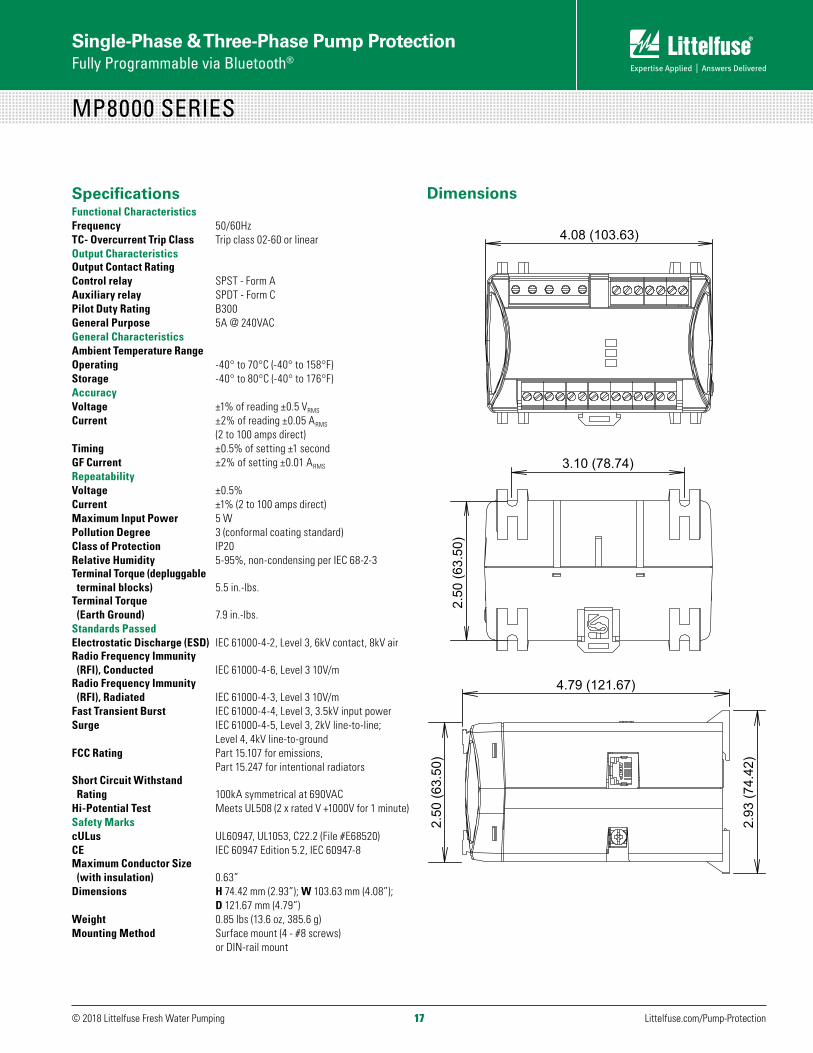
SpecificationsFunctional CharacteristicsFrequency 50/60HzTC- Overcurrent Trip Class Trip class 02-60 or linearOutput CharacteristicsOutput Contact Rating Control relay SPST - Form AAuxiliary relay SPDT - Form C Pilot Duty Rating B300General Purpose 5A @ 240VACGeneral CharacteristicsAmbient Temperature Range Operating -40° to 70°C (-40° to 158°F)Storage -40° to 80°C (-40° to 176°F)Accuracy Voltage ±1% of reading ±0.5 VRMS
Current ±2% of reading ±0.05 ARMS (2 to 100 amps direct)Timing ±0.5% of setting ±1 secondGF Current ±2% of setting ±0.01 ARMS
Repeatability Voltage ±0.5%Current ±1% (2 to 100 amps direct)Maximum Input Power 5 WPollution Degree 3 (conformal coating standard)Class of Protection IP20Relative Humidity 5-95%, non-condensing per IEC 68-2-3Terminal Torque (depluggable terminal blocks) 5.5 in.-lbs.Terminal Torque (Earth Ground) 7.9 in.-lbs.Standards PassedElectrostatic Discharge (ESD) IEC 61000-4-2, Level 3, 6kV contact, 8kV airRadio Frequency Immunity (RFI), Conducted IEC 61000-4-6, Level 3 10V/mRadio Frequency Immunity (RFI), Radiated IEC 61000-4-3, Level 3 10V/mFast Transient Burst IEC 61000-4-4, Level 3, 3.5kV input power Surge IEC 61000-4-5, Level 3, 2kV line-to-line; Level 4, 4kV line-to-ground FCC Rating Part 15.107 for emissions, Part 15.247 for intentional radiatorsShort Circuit Withstand Rating 100kA symmetrical at 690VACHi-Potential Test Meets UL508 (2 x rated V +1000V for 1 minute)Safety MarkscULus UL60947, UL1053, C22.2 (File #E68520)CE IEC 60947 Edition 5.2, IEC 60947-8 Maximum Conductor Size (with insulation) 0.63”Dimensions H 74.42 mm (2.93”); W 103.63 mm (4.08”); D 121.67 mm (4.79”)Weight 0.85 lbs (13.6 oz, 385.6 g)Mounting Method Surface mount (4 - #8 screws) or DIN-rail mount
Dimensions
4.79 (121.67)
2.9
3 (7
4.42
)
3.10 (78.74)
2.50
(63.
50)
4.08 (103.63)
2.5
0 (6
3.50
)
4.79 (121.67)
2.9
3 (7
4.42
)
3.10 (78.74) 2.
50 (6
3.50
) 4.08 (103.63)
2.5
0 (6
3.50
)
4.79 (121.67)
2.9
3 (7
4.42
)
3.10 (78.74)
2.50
(63.
50)
4.08 (103.63)
2.5
0 (6
3.50
)
Single-Phase & Three-Phase Pump Protection Fully Programmable via Bluetooth®
MP8000 SERIESBluetooth® Overload Relay
© 2018 Littelfuse Fresh Water Pumping Littelfuse.com/Pump-Protection 18
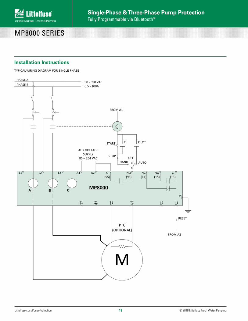
Installation Instructions
TYPICAL WIRING DIAGRAM FOR SINGLE-PHASE
NO(15)
C(13)
.I.2 I.1
MP8000
PTC (OPTIONAL)
RESET
FROM A2
PE
C(95)
L1 L3L2 A2
Z1 Z2 T1 T2
PHASE APHASE B
AUX VOLTAGE SUPPLY
A B C
NO(96)
NC(14)
C
PILOTSTART C
STOP
AUTOHANDOFF
FROM A1
M
A1
85 – 264 VAC
90 - 690 VAC0.5 - 100A
Single-Phase & Three-Phase Pump Protection Fully Programmable via Bluetooth®
MP8000 SERIES
19© 2018 Littelfuse Fresh Water Pumping Littelfuse.com/Pump-Protection19
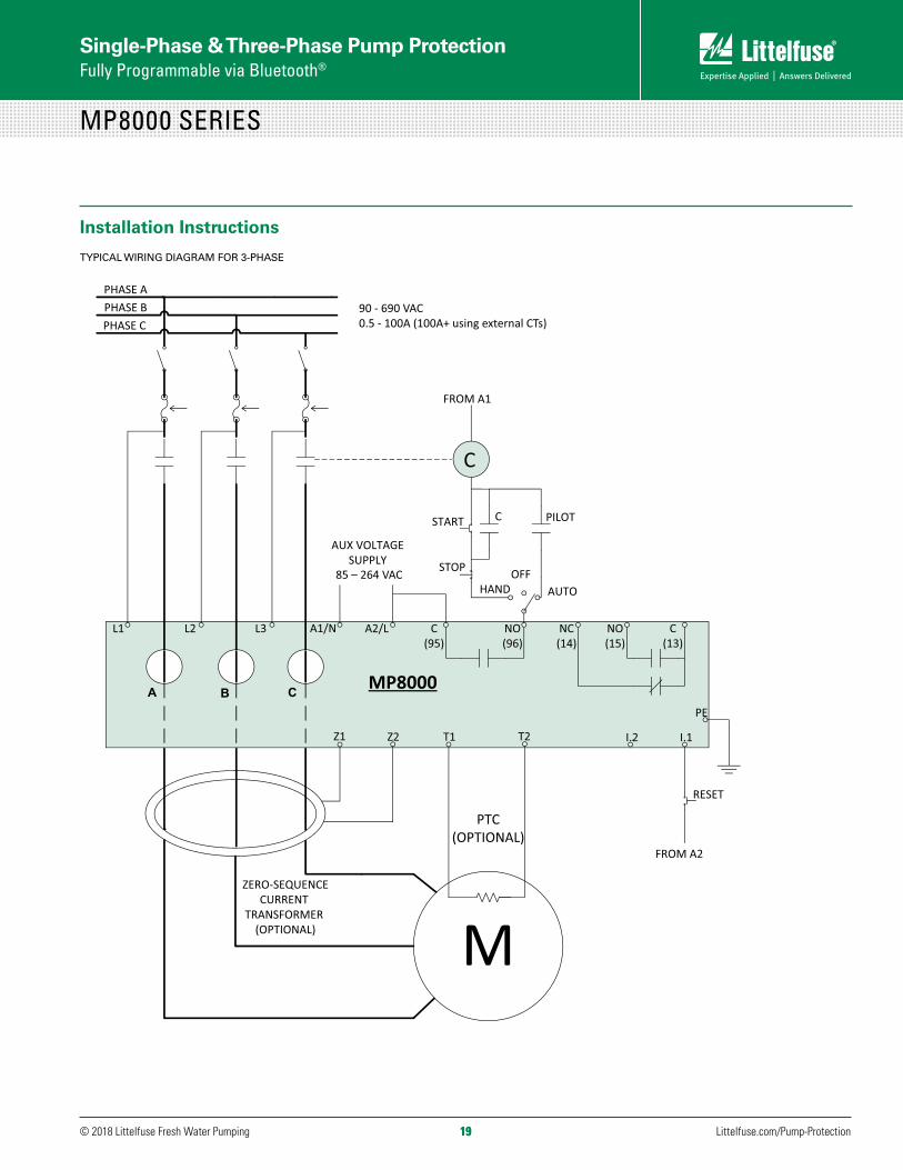
Installation Instructions
TYPICAL WIRING DIAGRAM FOR 3-PHASE
NO(15)
C(13)
.I.2 I.1
MP8000
PTC (OPTIONAL)
RESET
FROM A2
PE
C(95)
L1 L3L2 A2/L
Z1 Z2 T1 T2
PHASE APHASE BPHASE C
AUX VOLTAGE SUPPLY
ZERO-SEQUENCECURRENT
TRANSFORMER (OPTIONAL)
A B C
NO(96)
NC(14)
C
PILOTSTART C
STOP
AUTOHANDOFF
FROM A1
M
A1/N
85 – 264 VAC
90 - 690 VAC0.5 - 100A (100A+ using external CTs)

© 2018 Littelfuse Fresh Water Pumping Littelfuse.com/Pump-Protection 20
Single-Phase Pump Protection Programmable and Low-Range Programmable
DescriptionThe 77C-KW/HP is a programmable solid-state power monitor/overload relay that protects single-phase, 100-240VAC, 2-800 amp pumps (external CTs are required for 91-800 amps) from dry-well, dead-head, jammed impeller and other voltage and current conditions. The LR version is designed for easier installation at a lower 1-9 full load amps.
This Littelfuse 77C-KW/HP is programmable to your specific pumping application and provides a digital display of real-time data of the pump’s operation and fault conditions. The programmability allows the user to set trip points, trip delays and restart delays, to include protection from successive power outages and short-cycling/rapid-cycling caused by other motor controls, and delays for motor cool-down time and dry-well recovery time.
The 77C-KW/HP can be programmed and monitored through network communications, as well as hooked to a remote display unit to program and monitor the pump protection from an alternate location, or outside the electrical panel to avoid potential arc flash (arc flash is a serious hazard that can happen when opening an electrical panel).
SpecificationsFunctional SpecificationsProgrammable Operating Points LV-Low Voltage Threshold 85V - HV Setting HV-High Voltage Threshold LV Setting - 264VMULT-# of Conductors or CT Ratio (xxx:5) 77C-KW/HP: 1-10 Conductors or 100-800 Ratio 77C-LR-KW/HP: 1 or 2 conductors
OC-Overcurrent Threshold (20-100A) / MULT or 80-120% of CT PrimaryLP-Low Power Threshold See PWS below or 0=offTC-Overcurrent Trip Class 5, J5, 10, J10, 15, J15, 20, J20, 30, J30 or Lin (linear)PWS-Power Setpoint Range (1,2,3,4)(5,6,7,8) (settings within ranges are adjusted in LP settings) 1=0.01-0.99kw 5=0.01-1.33hp 2=1.00-9.95kw 6=1.34-13.3hp 3=10.0-99.5kw 7=13.4-133hp 4=100-650kw 8=134-871hp
RD1-Rapid-Cycle Timer 0, 2-500 SecondsRD2-Restart Delay after all faults except underload (motor cool down timer) 2-500 Minutes/SecondsRD3-Restart Delay after undercurrent (dry-well recovery timer) 2-500 Minutes/Seconds#RU-Number of restarts after underload 0, 1, 2, 3, 4, A (automatic)#RO-Number of restarts after overload 0, 1, 2, 3, 4, A (automatic) ADDR-RS485 Address A01-A99OPT1-To set linear OC trip delay when TC is set to Lin 2-60 secondsOPT2-To set RD2 & RD3 in either seconds or minutes 0, 1, 2, 3
MODEL DESCRIPTION
77C-KW/HP Programmable Pump Protection
77C-LR-KW/HP Low-Range Programmable Pump Protection
Ordering Information
77C-KW/HP / 77C-LR-KW/HPProgrammable Power Monitor/Overload Relay
21© 2018 Littelfuse Fresh Water Pumping Littelfuse.com/Pump-Protection21
Single-Phase Pump Protection Programmable and Low-Range Programmable
77C-KW/HP / 77C-LR-KW/HP
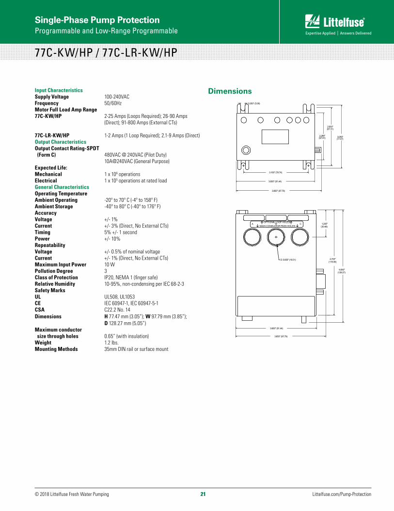
Input CharacteristicsSupply Voltage 100-240VACFrequency 50/60Hz Motor Full Load Amp Range77C-KW/HP 2-25 Amps (Loops Required); 26-90 Amps (Direct); 91-800 Amps (External CTs)
77C-LR-KW/HP 1-2 Amps (1 Loop Required); 2.1-9 Amps (Direct)Output CharacteristicsOutput Contact Rating-SPDT (Form C) 480VAC @ 240VAC (Pilot Duty) 10A@240VAC (General Purpose)Expected Life:Mechanical 1 x 10⁶ operationsElectrical 1 x 10⁵ operations at rated loadGeneral CharacteristicsOperating TemperatureAmbient Operating -20º to 70º C (-4º to 158º F)Ambient Storage -40º to 80º C (-40º to 176º F)AccuracyVoltage +/- 1%Current +/- 3% (Direct, No External CTs)Timing 5% +/- 1 second Power +/- 10%RepeatabilityVoltage +/- 0.5% of nominal voltageCurrent +/- 1% (Direct, No External CTs)Maximum Input Power 10 WPollution Degree 3Class of Protection IP20, NEMA 1 (finger safe)Relative Humidity 10-95%, non-condensing per IEC 68-2-3Safety Marks UL UL508, UL1053CE IEC 60947-1, IEC 60947-5-1CSA C22.2 No. 14 Dimensions H 77.47 mm (3.05”); W 97.79 mm (3.85”); D 128.27 mm (5.05”)Maximum conductor size through holes 0.65” (with insulation)Weight 1.2 lbs.Mounting Methods 35mm DIN rail or surface mount
Dimensions
3.100" (78.74)
3.850" (97.79)
3.600" (91.44)
2.280"
(67.31)
3.050"
3.850" (97.79)
3.600" (91.44)
5.050"
4.700"
1.200"
(57.91)
2.650"
(77.47)
(30.48)
(128.27)
(119.38)D. 0.650" (16.51)
0.200" (5.08)
OPTIONAL LOOP HOLESMAIN CONDUCTOR PASS HOLES
A B C

© 2018 Littelfuse Fresh Water Pumping Littelfuse.com/Pump-Protection 22
Single-Phase Pump Protection Programmable and Low-Range Programmable
77C-KW/HP / 77C-LR-KW/HP
Installation Instructions
TYPICAL WIRING DIAGRAM FOR 77C-KW/HP & 77C-LR-KW/HP SERIES
L1
CONTACTOR
COIL
CONTROL POWER
START STOP HAND
AUTO PILOT
M
A
TO MOTOR
B C
OFF
240 VAC OR LESS
NOTE: PHASES A&C ARE INACTIVE
L2
A B C
Figure 2: Typical Wiring Diagram for 77C-KW/HP
LITTELFUSE RECOMMENDS USING CTs WITH TERMINALS TO SIMPLIFY INSTALLATION.
NOTE: PHASES A & C ARE INACTIVE. USE PHASE B FOR ALL ACTIVE CURRENT MEASUREMENTS. CT SECONDARY MUST MAKE FIVE PASSES THROUGH THE PHASE B CONDUCTOR WINDOW.
Table 1: Wiring configuration for 77C-KW/HP based on motor amps.
FULL LOAD AMPS # OF CONDUCTORS THROUGH B
MULT TO PROGRAM (CT RATIO)
2.0 - 2.5 10 10
2.6 - 3.0 9 9
3.1 - 3.5 8 8
3.6 - 4.0 7 7
4.1 - 5.0 6 6
5.1 - 6.0 5 5
6.1 - 8.0 4 4
8.1 - 12 3 3
13 - 25 2 2
26 - 90 1 1
EXTERNAL CTS REQUIRED. SEE WIRING DIAGRAM FOR EXTERNAL CTS.
91 - 110 5 100 (100:5)
111 - 160 5 150 (150:5)
161 - 220 5 200 (200:5)
221 - 320 5 300 (300:5)
321 - 420 5 400 (400:5)
421 - 520 5 500 (500:5)
521 - 620 5 600 (600:5)
621 - 800 5 800 (800:5)
Table 2: Wiring configuration for 77C-LR-KW/HP based on motor amps.
FULL LOAD AMPS # OF CONDUCTORS THROUGH WINDOW B MULT
1.0 - 2.0 2 2
2.1 - 9.0 1 1
Programming1. Rotate the MODE SELECT switch to the parameter to be
programmed. It is recommended that PWS be programmed first on the KW/HP versions.
2. Press and hold the RESET/PROGRAM button.
3. While holding the RESET/PROGRAM button, rotate the DISPLAY/PROGRAM knob until the proper setting for the parameter that is being programmed is displayed.
4. Release the RESET/PROGRAM button. This stores the new parameter in the nonvolatile memory. If the number changes back to what is was before programming, then the tamper guard is on and will need to be unlocked before programming can be completed.
5. Continue steps 1-4 until all parameters are programmed.
23© 2018 Littelfuse Fresh Water Pumping Littelfuse.com/Pump-Protection23
Single-Phase Pump Protection Programmable and Low-Range Programmable
77C-KW/HP / 77C-LR-KW/HP
Suggested Settings(Consult the Motor Manufacturer for their recommendations.)
LV/HV- The recommended settings for LV (low voltage) and HV (high voltage) depend on many factors such as motor usage, motor size, environmental factors and tolerance of the motor. The motor manufacturer should be consulted for HV and LV settings. However, the NEMA MG1 standard recommends that LV and HV be set to no more than ±10% of the motor’s nameplate voltage. The setting can be determined by multiplying the motor’s nameplate voltage by the recommended percent over and under voltage. (e.g., The motor nameplate voltage is 230 V, set LV to 0.9 x 230 = 207, set HV to 1.10 x 230 = 253) LV can not be set higher than HV, so HV may have to be adjusted higher before the proper LV setting can be programmed.
MULT- The multiplication factor for determining true current settings and represents the number of conductors passing through the main current window marked B, or current transformer ratio of external CTs. The appropriate number can be determined from Table 1 (Table 2 for -LR version) on page 18. MULT must be correctly programmed in order to accurately program the current settings.
OC- Represents the motor’s maximum service factor amperage. The OC (overcurrent) setting depends on many factors such as motor usage, motor size, environmental factors and tolerance of the motor. The motor manufacturer should be consulted for OC settings. However, OC is typically between 110% and 125% of full load amperage (FLA) and may be referred to as maximum amps or service factor amps.
LP- (Low power setting) is used to shut down the motor or pump on an underload condition. Setting LP to 0 disables the underload trip feature. LP is set in either kilowatts (KW) or horsepower (HP) depending on the PWS setting.
NOTE: PWS must be set before setting LP
TC- Designates the trip class for overload protection. The trip class defines the trip delay when an overload is detected. Trip class is determined by the type of motor and application. Your motor manufacturer should be consulted for the proper setting. Table 4 shows the trip class and a general description of the applications and Table 5 shows the trip class curves.
RD1- is the rapid-cycle timer. It will engage when the motor is first powered-up or after the motor controls shut down the motor. An RD1 setting of 20-30 seconds will generally protect the motor from rapid, successive power outages or short cycling caused by the motor controls. A setting of 0 seconds will allow the motor to start immediately after power-up or after a normal shutdown.
RD2- is the restart delay after the overload relay trips on overcurrent. This delay allows the motor to cool down after experiencing an overcurrent. It is also known as a motor cool down timer. Your motor manufacturer should be contacted to determine this setting. Under normal circumstances, a setting of 5-10 minutes will give the motor enough time to cool down between faults.
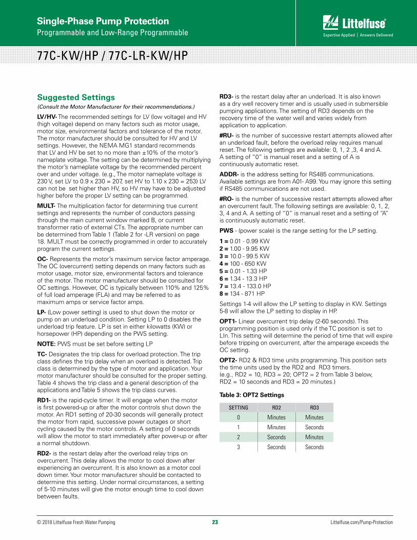
RD3- is the restart delay after an underload. It is also known as a dry well recovery timer and is usually used in submersible pumping applications. The setting of RD3 depends on the recovery time of the water well and varies widely from application to application.
#RU- is the number of successive restart attempts allowed after an underload fault, before the overload relay requires manual reset. The following settings are available: 0, 1, 2 ,3, 4 and A. A setting of “0” is manual reset and a setting of A is continuously automatic reset.
ADDR- is the address setting for RS485 communications. Available settings are from A01- A99. You may ignore this setting if RS485 communications are not used.
#RO- is the number of successive restart attempts allowed after an overcurrent fault. The following settings are available: 0, 1, 2, 3, 4 and A. A setting of “0” is manual reset and a setting of “A” is continuously automatic reset.
PWS - (power scale) is the range setting for the LP setting.
1 = 0.01 - 0.99 KW 2 = 1.00 - 9.95 KW 3 = 10.0 - 99.5 KW 4 = 100 - 650 KW 5 = 0.01 - 1.33 HP 6 = 1.34 - 13.3 HP 7 = 13.4 - 133.0 HP 8 = 134 - 871 HP
Settings 1-4 will allow the LP setting to display in KW. Settings 5-8 will allow the LP setting to display in HP.
OPT1- Linear overcurrent trip delay (2-60 seconds). This programming position is used only if the TC position is set to LIn. This setting will determine the period of time that will expire before tripping on overcurrent, after the amperage exceeds the OC setting.
OPT2- RD2 & RD3 time units programming. This position sets the time units used by the RD2 and RD3 timers. (e.g., RD2 = 10, RD3 = 20; OPT2 = 2 from Table 3 below, RD2 = 10 seconds and RD3 = 20 minutes.)
Table 3: OPT2 Settings
SETTING RD2 RD3
0 Minutes Minutes
1 Minutes Seconds
2 Seconds Minutes
3 Seconds Seconds

© 2018 Littelfuse Fresh Water Pumping Littelfuse.com/Pump-Protection 24
Single-Phase Pump Protection Programmable and Low-Range Programmable
77C-KW/HP / 77C-LR-KW/HPProgrammable Power Monitor/Overload Relay
Table 4: Trip Class Table
TRIP CLASS APPLICATION DESCRIPTION
5Small fractional horsepower motors where acceleration times are almost instantaneous or where extremely quick trip times are required.
10(Fast Trip) Hermetic refrigerant motors, compressors, submersible pumps and general purpose motors that reach rated speed in less than 4 seconds.
15 Specialized applications.
20 (Standard Trip) Most NEMA-rated general purpose motors will be protected by this setting.
30 (Slow Trip) Motors with long acceleration times (>10 seconds) or high inertia loads.
J Prefix
Programming any of the trip classes with the J Prefix will enable jam protection. This additional protection is enabled 1 minute after the motor starts and provides a 2 second trip time for motors exceeding 400% of the OC setting, regardless of trip class.
Lln
Programming the trip class to Lln disables the normal trip classes shown above and enables a linear trip delay on overcurrent. The linear trip delay is set in program position OPT1.
Table 5: Overload Trip Curves
10000
1000
100
10
0 300 400 500
% of OC Setting
Trip
Tim
e (S
econ
ds)
600 700 800 900 1000
Class 10
Class 30
Class 20Class 15
Class 5
2001001
Table 5: Overload Trip CurvesMulti-Function System DisplayThe output display shows various system operating parameters (L1-L2 Voltage, L2 Current (B), kilowatts, and horsepower).
When MODE SELECT is in the RUN position, the LED will display one of the above operating parameters. To select or change the displayed parameter, turn the DISPLAY/PROGRAM knob to the desired position as shown on its label.
The multifunction display is used for programming purposes and also announces system faults such as low voltage and high voltage. Any time MODE SELECT is in the RUN position, the RESET/PROGRAM button may be pushed to view the last fault which occurred. Table 6 below shows the possible messages.
Table 6: Output Displays
DISPLAYED MESSAGE MEANING
oc Tripped on Overcurrent
LPR Tripped on Low Power
H I High Voltage (won’t allow the motor to start)
Lo Low Voltage (won’t allow the motor to start)
oFF A stop command was issued from a remote source.
OperationOnce the power monitor has been programmed, turn the MODE SELECT to the RUN position. The LED display will flash RUN alternatively with a number representing the parameter indicated by the DISPLAY/PROGRAM knob. After the period of time programmed into RD1, the output contacts will close and the value of the parameter indicated by the DISPLAY/PROGRAM knob will appear on the LED display. If a message other than those indicated above is shown on the LED display, see Troubleshooting Chart in Table 7 to diagnose the problem.
Table 7: Troubleshooting Chart
PROBLEM SOLUTION
The unit will not start. Display alternates “HI” or “Lo” with the DISPLAY/PROGRAM knob parameter value.
The incoming voltage is not within the limits programmed in the HV and LV settings. Adjust the DISPLAY/PROGRAM knob to read the incoming line voltage value. Correct the incoming power problem and check programmed limits to verify they are correct.
Display alternates “oc” with RUN.
The overload relay has tripped on overcurrent and is timing down RD2 before restarting.
Display alternates LPr with RUN.
The overload relay has tripped on low power and is timing down RD3 before restarting.
Display is showing a solid “oc.”
The unit has tripped on overcurrent and manual reset is required because of the programmed setting in #RO. Check the system for problems (like a jam) that would produce the overload fault.
Display is showing the solid “LPr.”
The unit has tripped on low power and a manual reset is required because of the programmed setting in #RU. Check the system for problems that would produce an underload condition like a dead-head or a lack of liquid to the pump.
Unable to change parameters. See Tamper Guard.

25© 2018 Littelfuse Fresh Water Pumping Littelfuse.com/Pump-Protection25
Three-Phase Pump Protection Fully Programmable
777-P2 SERIESElectronic Overload Relay
DescriptionThe 777-P2 Series is a family of fully programmable electronic overload relays. They are designed to monitor and protect any 3-phase 200-480VAC motor drawing 2-800 full load amps (external CTs are required above 90 amps). They provide unsurpassed protection from faulty voltage, underload and overload conditions. The 777-P2 can be used in a variety of 3-phase applications and features an undercurrent trip point (adjustable on the unit) that is favorable anytime there is a notable difference between a load and no-load condition. The overload relay displays voltage and current on the face of the unit. The LR version is designed for easier installation at a lower range of 1-9 full load amps. The HVR version is designed with a high voltage relay for control circuits operating at 480VAC.
The 777-P2 Series units incorporate a 3-digit LED display that is used for programming, providing real-time operational information, and displaying diagnostic codes to aid in troubleshooting a fault condition.
The unit’s many features include enhanced trip classes beyond the NEMA standard trip classes. The settable trip class range is 2-60, with or without jam protection, and a secondary linear trip delay can be set with a range of 0-60 seconds. If both trip class and linear trip delay are set, the 777-P2 will follow the faster trip time. Another feature is the automatic dry-well recovery timer that allows the unit to automatically select a restart delay based on the last cycle’s run time. This allows the 777-P2 to optimize restart delay times.
Network communications: compatible with Modbus, DeviceNet™, Profibus, or Ethernet using optional communications module.
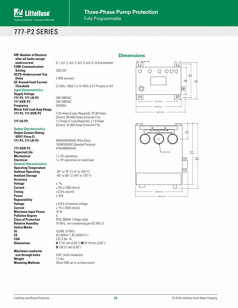
SpecificationsFunctional SpecificationsProgrammable Operating Points LV-Low Voltage Threshold 170-524VHV-High Voltage Threshold 172-528V VUB-Voltage Unbalance Threshold 2-25% or 999 (disable)MULT-# of Conductors or CT Ratio (xxx:5) 1-10, 100, 150, 200, 300, 400, 500, 600, 700, 800OC-Overcurrent Threshold (20-100A) ÷ MULT or 80-140% of CT PrimaryUC-Undercurrent Threshold 0, (10-98A) ÷ MULT or 40-140% of CT PrimaryCUB-Current Unbalance Threshold 2-50% or 999 (disable)TC-Overcurrent Trip Class 2-60, J2-J60, L00-L60, oFF RD1-Rapid-Cycle Timer 0-999 secondsRD2-Restart Delay after all faults except undercurrent (motor cool down timer) 2-500 minutesRD3-Restart Delay after undercurrent (dry-well recovery timer) 2-500 minutes, A (automatic)#RU-Number of restarts after undercurrent 0, 1, 2, 3, 4, A (automatic)ADDR-RS485 Address A01-A99
Ordering Information
MODEL LINE VOLTAGE
MOTOR FULL AMP RANGE DESCRIPTION
777-P2 200-480VAC (3-phase)
2-800A (external CTs required above 90A)
Provides low and high power trip*, linear overcurrent trip, and 480VA @ 240VAC output SPDT relay contacts
777-LR-P2 200-480VAC (3-phase)
1-800A (external CTs required above 9A)
Protects low range motors when wired directly or with 10-800 FLA with use of external CTs
777-HVR-P2 340-480VAC (3-phase)
2-800A (external CTs required above 90A)
Provides low and high power trip*, linear overcurrent trip, and 470VA @ 600VAC output SPDT relay contacts. Required when a control power transformer (CPT) is not used with a 480V system
* Network programmable only
© 2018 Littelfuse Fresh Water Pumping Littelfuse.com/Pump-Protection 26
Three-Phase Pump Protection Fully Programmable
777-P2 SERIES
#RF-Number of Restarts after all faults except undercurrent 0, 1, oc1, 2, oc2, 3, oc3, 4, oc4, A, ocA (automatic)COM-Communication Setting C00-C07UCTD-Undercurrent Trip Delay 2-999 secondsGF-Ground Fault Current Threshold (3-20A) ÷ MULT or 12-40% of CT Primary or oFFInput CharacteristicsSupply Voltage777-P2, 777-LR-P2 200-480VAC777-HVR-P2 340-480VACFrequency 50/60HzMotor Full Load Amp Range777-P2, 777-HVR-P2 2-20 Amps (Loops Required); 20-90 Amps (Direct); 80-800 Amps (External CTs)777-LR-P2 1-2 Amps (1 Loop Required); 2.1-9 Amps (Direct); 10-800 Amps (External CTs)Output CharacteristicsOutput Contact Rating- SPDT (Form C) 777-P2, 777-LR-P2 480VA@240VAC (Pilot Duty), 10A@240VAC (General Purpose)777-HVR-P2 470VA@600VAC Expected Life Mechanical 1 x 10⁶ operationsElectrical 1 x 10⁵ operations at rated loadGeneral CharacteristicsOperating Temperature Ambient Operating -20° to 70° C (-4° to 158° F)Ambient Storage -40° to 80° C (-40° to 176° F)AccuracyVoltage ± 1%Current ± 3% (<100A direct)Timing ± 0.5% secondPower ± 10%Repeatability Voltage ± 0.5% of nominal voltageCurrent ± 1% (<100A direct)Maximum Input Power 10 WPollution Degree 3Class of Protection IP20, NEMA 1 (finger safe)Relative Humidity 10-95%, non-condensing per IEC 68-2-3Safety MarksUL UL508, UL1053 CE IEC 60947-1, IEC 60947-5-1 CSA C22.2 No. 14 Dimensions H 77.47 mm (3.05”); W 97.79 mm (3.85”); D 128.27 mm (5.05”)Maximum conductor size through holes 0.65” (with insulation)Weight 1.2 lbs. Mounting Methods 35mm DIN rail or surface mount
Dimensions
3.100" (78.74)
3.850" (97.79)
3.600" (91.44)
2.280"
(67.31)
3.050"
3.850" (97.79)
3.600" (91.44)
5.050"
4.700"
1.200"
(57.91)
2.650"
(77.47)
(30.48)
(128.27)
(119.38)D. 0.650" (16.51)
0.200" (5.08)
OPTIONAL LOOP HOLESMAIN CONDUCTOR PASS HOLES
A B C
27© 2018 Littelfuse Fresh Water Pumping Littelfuse.com/Pump-Protection27
Three-Phase Pump Protection Fully Programmable
777-KW/HP-P2 SERIESElectronic Power Monitors
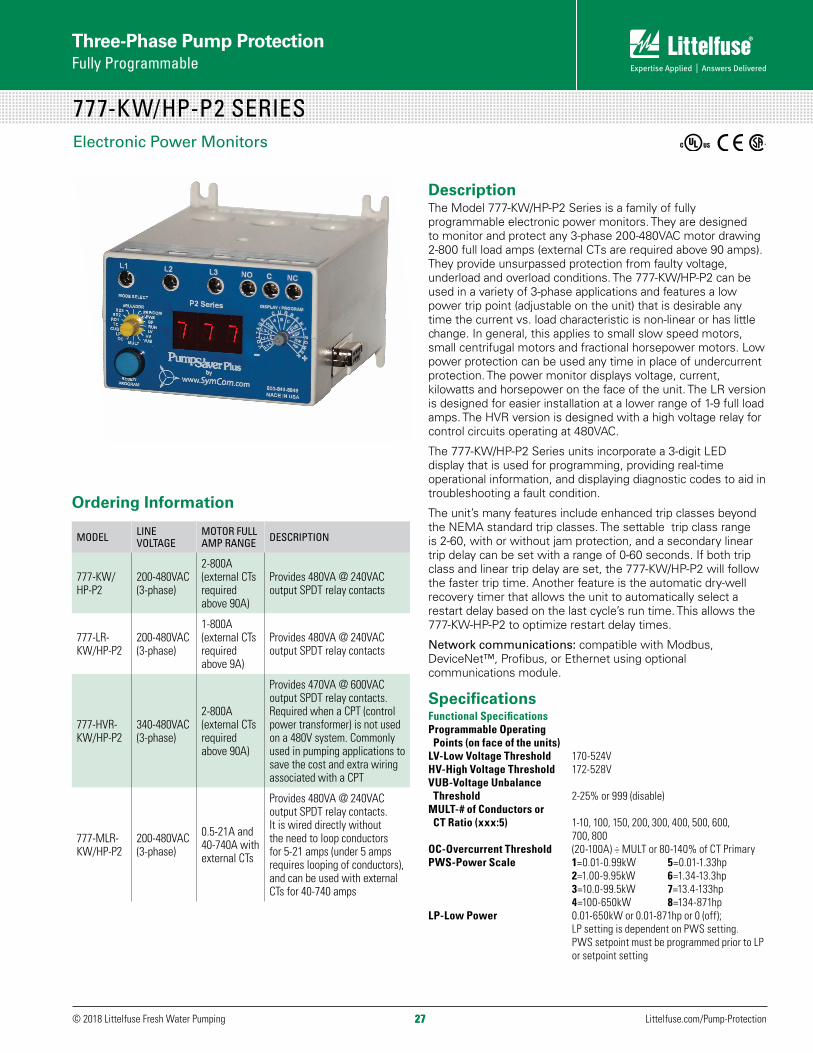
DescriptionThe Model 777-KW/HP-P2 Series is a family of fully programmable electronic power monitors. They are designed to monitor and protect any 3-phase 200-480VAC motor drawing 2-800 full load amps (external CTs are required above 90 amps). They provide unsurpassed protection from faulty voltage, underload and overload conditions. The 777-KW/HP-P2 can be used in a variety of 3-phase applications and features a low power trip point (adjustable on the unit) that is desirable any time the current vs. load characteristic is non-linear or has little change. In general, this applies to small slow speed motors, small centrifugal motors and fractional horsepower motors. Low power protection can be used any time in place of undercurrent protection. The power monitor displays voltage, current, kilowatts and horsepower on the face of the unit. The LR version is designed for easier installation at a lower range of 1-9 full load amps. The HVR version is designed with a high voltage relay for control circuits operating at 480VAC.
The 777-KW/HP-P2 Series units incorporate a 3-digit LED display that is used for programming, providing real-time operational information, and displaying diagnostic codes to aid in troubleshooting a fault condition.
The unit’s many features include enhanced trip classes beyond the NEMA standard trip classes. The settable trip class range is 2-60, with or without jam protection, and a secondary linear trip delay can be set with a range of 0-60 seconds. If both trip class and linear trip delay are set, the 777-KW/HP-P2 will follow the faster trip time. Another feature is the automatic dry-well recovery timer that allows the unit to automatically select a restart delay based on the last cycle’s run time. This allows the 777-KW-HP-P2 to optimize restart delay times.
Network communications: compatible with Modbus, DeviceNet™, Profibus, or Ethernet using optional communications module.
SpecificationsFunctional SpecificationsProgrammable Operating Points (on face of the units)LV-Low Voltage Threshold 170-524VHV-High Voltage Threshold 172-528VVUB-Voltage Unbalance Threshold 2-25% or 999 (disable)MULT-# of Conductors or CT Ratio (xxx:5) 1-10, 100, 150, 200, 300, 400, 500, 600, 700, 800OC-Overcurrent Threshold (20-100A) ÷ MULT or 80-140% of CT PrimaryPWS-Power Scale 1=0.01-0.99kW 5=0.01-1.33hp 2=1.00-9.95kW 6=1.34-13.3hp 3=10.0-99.5kW 7=13.4-133hp 4=100-650kW 8=134-871hpLP-Low Power 0.01-650kW or 0.01-871hp or 0 (off); LP setting is dependent on PWS setting. PWS setpoint must be programmed prior to LP or setpoint setting
Ordering Information
MODEL LINE VOLTAGE
MOTOR FULL AMP RANGE DESCRIPTION
777-KW/HP-P2
200-480VAC (3-phase)
2-800A (external CTs required above 90A)
Provides 480VA @ 240VAC output SPDT relay contacts
777-LR-KW/HP-P2
200-480VAC (3-phase)
1-800A (external CTs required above 9A)
Provides 480VA @ 240VAC output SPDT relay contacts
777-HVR-KW/HP-P2
340-480VAC (3-phase)
2-800A (external CTs required above 90A)
Provides 470VA @ 600VAC output SPDT relay contacts. Required when a CPT (control power transformer) is not used on a 480V system. Commonly used in pumping applications to save the cost and extra wiring associated with a CPT
777-MLR-KW/HP-P2
200-480VAC (3-phase)
0.5-21A and 40-740A with external CTs
Provides 480VA @ 240VAC output SPDT relay contacts. It is wired directly without the need to loop conductors for 5-21 amps (under 5 amps requires looping of conductors), and can be used with external CTs for 40-740 amps

© 2018 Littelfuse Fresh Water Pumping Littelfuse.com/Pump-Protection 28
Three-Phase Pump Protection Fully Programmable
777-KW/HP-P2 SERIES
CUB-Current Unbalance Threshold 2-50% or 999 (disable)TC-Overcurrent Trip Class 2-60, J2-J60, L00-L60, oFFRD1-Rapid-cycle Timer 0-999 secondsRD2- Restart Delay after all faults except underload motor cool-down timer) 2-500 minutesRD3-Restart Delay after underload (dry-well recovery timer) 2-500 minutes, A (automatic)#RU-Number of Restarts after underload 0, 1, 2, 3, 4, A (automatic)ADDR-RS485 Address A01-A99#RF-Number of Restarts after all faults except underload 0, 1, oc1, 2, oc2, 3, oc3, 4, oc4, A, ocA (automatic)COM-Communication Setting C00-C07GF-Ground Fault Current Threshold (3-20A) ÷ MULT of 12-40% of CT Primary or oFFInput CharacteristicsSupply Voltage777-KW/HP-P2, 777-LR-KW/HP-P2, 777-MLR-KW/HP-P2 200-480VAC 777-HVR-KW/HP-P2 340-480VACFrequency 50/60HzMotor Full Load Amp Range777-KW/HP-P2, 777-HVR-KW/HP-P2 2-20 Amps (Loops Required); 20-90 Amps (Direct); 80-800 Amps (External CTs)777-LR-KW/HP-P2 1-2 Amps (1 Loop Required); 2.1-9 Amps (Direct); 10-800 Amps (External CTs)777-MLR-KW/HP-P2 0.5-10.5 Amps (Loops Required), 5-21 (Direct), 40-740 (External CTs)Output CharacteristicsOutput Contact Rating-SPDT (Form C)777-KW/HP-P2, 7 77-LR-KW/HP-P2, 77-MLR-KW/HP-P2 480VA@240VAC (Pilot Duty) 10A@240VAC (General Purpose)777-HVR-KW/HP-P2 470VA@600VACExpected LifeMechanical 1 x 10⁶ operationsElectrical 1 x 10⁵ operations at rated loadGeneral CharacteristicsOperating TemperatureAmbient Operating -20º to 70º C (-4º to 158º F)Ambient Storage -40º to 80º C (-40º to 176º F)AccuracyVoltage ± 1%Current ± 3% (<100A direct)Timing ± 0.5% secondPower ± 10%
RepeatabilityVoltage ± 0.5% of nominal voltageCurrent ± 1% (<100A direct)Maximum Input Power 10 WPollution Degree 3Class of Protection IP20, NEMA 1 (finger safe)Relative Humidity 10-95%, non-condensing per IEC 68-2-3Safety MarksUL UL508, UL1053CE IEC 60947-1, IEC 60947-5-1CSA C22.2 No. 14 Dimensions H 77.47 mm (3.05”); W 97.79 mm (3.85”); D 128.27 mm (5.05”)Maximum conductor size through holes 0.65” (with insulation)Weight 1.2 lbs.Mounting Methods 35mm DIN rail or surface mount
Dimensions
3.100 [78.74]
3.850 [97.79]
3.600 [91.44]
2.280[57.91]
3.050[77.47]
1.200[30.48]
3.850 [97.79]
3.600 [91.44]
2.650[67.31]
D. 0.650 [16.51]
0.200 [5.08]
OPTIONAL LOOP HOLES
MAIN CONDUCTORPASS HOLESA B C
inches [millimeters]
4.700[119.38]
5.050[128.27]

29© 2018 Littelfuse Fresh Water Pumping Littelfuse.com/Pump-Protection29
Three-Phase Pump Protection Fully Programmable
777-P2 / 777-KW/HP-P2 SERIES INSTALLATION INSTRUCTIONS
Installation InstructionsTYPICAL WIRING DIAGRAM FOR 777-KW/HP-P2 SERIES
PILOT
Table 8: Wiring Configuration for 777-P2 & 777-KW/HP-P2 Based on Motor Full Load Amps
RECOMMENDED FULL LOAD AMPS OC RANGE (AMPS)
UC RANGE (AMPS)
# OF PASSES THROUGH EACH WINDOW
MULT (CT RATIO)
2-2.5 2-10 0, 1-9.8 10 10
2.5-3 2.2-11.1 0, 1.1-10.8 9 9
3-3.5 2.5-12.5 0, 1.2-12.2 8 8
3.5-4 2.8-14.3 0, 1.4-14 7 7
4-5 3.3-16.7 0, 1.6-16.3 6 6
5-6 4-20.1 0, 2-19.6 5 5
6-8 5-25.1 0, 2.5-24.5 4 4
8-12 6.6-33.5 0, 3.3-32.6 3 3
12-20 10-50.3 0, 5-49 2 2
20-90 20-100 0, 10-98 1 1
80-110 80-140 0, 40-140 5 100 (100:5)
110-160 120-210 0, 60-210 5 150 (150:5)
160-220 160-280 0, 80-280 5 200 (200:5)
220-320 240-420 0, 120-420 5 300 (300:5)
320-420 320-560 0, 160-560 5 400 (400:5)
400-520 400-700 0, 200-700 5 500 (500:5)
480-600 480-840 0, 240-840 5 600 (600:5)
540-700 560-980 0, 280-980 5 700 (700:5)
560-800 640-992/FFF 0, 320-992/FFF 5 800 (800:5)
LITTELFUSE RECOMMENDS USING CTs WITH TERMINALS TO SIMPLIFY INSTALLATION.
12 - 16 AWG STRANDED
WIRE
Note: All CTs must face the same direction and all CT secondaries must be wired identically, i.e. all X1 terminals enter the main (round) window and returns to H1 terminal after exiting the loop conductor window (rectangle).
Every CT secondary must make five passes through the corresponding main conductor window on the modell 777.
Every CT secondary must make a single pass through the corresponding main conductor window on the LR versions of the 777 Plus Series
CURRENT TRANSFORMER WIRING DIAGRAM FOR 777-KW/HP-P2 SERIES
Three-Phase Pump Protection Fully Programmable

© 2018 Littelfuse Fresh Water Pumping Littelfuse.com/Pump-Protection 30
Three-Phase Pump Protection Fully Programmable
Table 9: Wiring Configuration for 777-LR-P2 & 777-LR-KW/HP-P2 Based on Motor Full Load Amps
RECOMMENDED FULL LOAD AMPS OC RANGE (AMPS)
UC RANGE (AMPS)
# OF PASSES THROUGH EACH WINDOW
MULT (CT RATIO)
1.0-2.0 1.0-5.0 0, 0.5-4.9 2 2
2.1-9.0 2.0-10.0 0, 1-9.8 1 1
10-25 10-50 0, 5-49 2 25 (50:5)
20-50 20-100 0, 10-98 1 50 (50:5)
30-75 30-150 0, 15-147 1 75 (75:5)
40-100 40-200 0, 20-196 1 100 (100:5)
60-150 60-300 0, 30-294 1 150 (150:5)
80-200 80-400 0, 40-392 1 200 (200:5)
120-300 120-600 0, 60-588 1 300 (300:5)
160-400 160-800 0, 80-784 1 400 (400:5)
200-500 200-999 0, 100-980 1 500 (500:5)
240-600 240-999 0, 120-999 1 600 (600:5)
280-700 280-999 0, 140-999 1 700 (700:5)
320-800 320-999 0, 160-999 1 800 (800:5)
Table 10: Wiring Configuration for 777-MLR-KW/HP-P2 Based on Motor Full Load Amps
RECOMMENDED FULL LOAD AMPS OC RANGE (AMPS)
# OF PASSES THROUGH EACH WINDOW
MULT (CT RATIO)
0.5-2.10 0.5-2.7 10 10
0.5-2.3 0.5-3 9 9
0.6-2.6 0.6-3.3 8 8
0.7-3 0.7-3.8 7 7
0.8-3.5 0.8-4.5 6 6
1-4.25 1-5.4 5 5
1.2-5.25 1.2-6.7 4 4
1.6-7 1.6-9 3 3
2.5-10.5 2.5-13.5 2 2
5-21 5-27 1 1
40-90 20-108 5 100 (100:5)
60-135 30-162 5 150 (150:5)
80-180 40-216 5 200 (200:5)
120-270 60-324 5 300 (300:5)
160-360 80-432 5 400 (400:5)
200-450 100-540 5 500 (500:5)
240-540 120-648 5 600 (600:5)
270-630 140-756 5 700 (700:5)
320-740 160-864 5 800 (800:5)
777-P2 / 777-KW/HP-P2 SERIES INSTALLATION INSTRUCTIONS
31© 2018 Littelfuse Fresh Water Pumping Littelfuse.com/Pump-Protection31
Three-Phase Pump Protection Fully Programmable
777-P2 / 777-KW/HP-P2 SERIES INSTALLATION INSTRUCTIONS
ProgrammingTo program prior to installation, connect the 9V battery cable to the pins on the left side of the unit (when looking at the display), and then attach a standard 9V battery to the cable. The 9V battery cable is keyed for proper installation. If the cable is connected improperly, the unit will not power its display. DO NOT connect the battery when line voltage is present. The unit cannot be tested for proper operation or communications using a 9V battery. For testing purposes, 3-phase power must be used with a minimum voltage of 200VAC. Follow all safety warnings when dealing with hazardous voltages.
1. Rotate the MODE SELECT switch to the parameter to be programmed. It is recommended that PWS be programmed first on the KW/HP versions.
2. Press and hold the RESET/PROGRAM button.
3. While holding the RESET/PROGRAM button, rotate the DISPLAY/PROGRAM knob until the proper setting for the parameter that is being programmed is displayed.
4. Release the RESET/PROGRAM button. This stores the new parameter in the nonvolatile memory. If the number changes back to what is was before programming, then the tamper guard is on and will need to be unlocked before programming can be completed. (See Tamper Guard section in the install manual if necessary.)
5. Continue steps 1-4 until all parameters are programmed.
Programmable ParametersThe following settings MUST be programmed by the user in order to provide proper protection for the application. Settings vary by situation and application and should be selected and tested for each unique installation. All parameters are actual values except for the VUB and CUB settings; these are programmed as percentages. The range each parameter can be programmed is found in the electrical specifications table. Failure to program all setpoints could result in nuisance tripping or prevent the device from protecting the motor. Always use the proper CTs for the motor full-load amperage (FLA).
LV/HV - Low Voltage/High Voltage. The recommended settings for LV (low voltage) and HV (high voltage) according to the NEMA MG1 standard are ±10% of the motor’s nameplate voltage. Generally, the motor manufacturer should be contacted to verify these limits. High and low voltage trips are based on average voltage measured. Never set LV higher than HV.
Example: Nameplate voltage = 230 V LV = 90% x 230 =207 V HV = 110% x 230 = 253 V
VUB - Voltage Unbalance. The NEMA MG1 standard says a motor should not be operated above a 1% voltage unbalance without derating the motor. Most utility supplied power sources have a difficult time sustaining a 1% VUB. The motor manufacturer should be consulted for an exact VUB setting. Setting VUB to 999 will disable voltage unbalance protection, but will not disable voltage single-phase protection. Voltage unbalance is calculated as follows:
%Voltage Unbalance = [(Maximum deviation from the average)/Average] x 100%
Example: Measured line-line voltages = 203, 210, and 212. The average = (203+210+212)/3 = 208.3. The maximum deviation from the average is the greatest difference between the average voltage (208.3) and any one voltage reading: 212-208.3 = 3.7, 210-208.3 = 1.7 and 208.3-203 = 5.3. The maximum deviation from the average is 5.3, thus voltage unbalance = 5.3/208.3 x 100 = 2.5%.
MULT - (multiplier) setting is found in Table 8 (Table 9 for -LR version, Table 10 for -MLR version). The MULT setting is determined by the number of passes of the motor leads or the size of external CTs and the full-load amps of the motor the unit will be monitoring. MULT sets the trip point range for overcurrent and ground fault current faults. Set MULT first, then set OC and GF.
OC - Overcurrent. Is typically set to the service-factor amperage (SFA) of the motor or 100-135% of motor full-load amps (FLA), which are determined by the motor manufacturer. If any one leg exceeds the OC setting, the unit will trip according to the Trip Class (TC) settings.
NOTE: When using external CTs, do not set OC greater than the thermal rating of the CTs
UC - Undercurrent (for non-KW/HP versions). Is most commonly set to 80% of the full-load amperage (FLA) of the motor. This is usually adequate for protection of loss of load for many pumps and motors, including submersibles. If the motor is drawing less than full-load amperage, then the UC may be set lower than 80% of FLA for adequate protection. Centrifugal/booster pumps may have to be set to something higher than 80% of FLA for adequate protection. UC can be set to 0 if UC protection is not desired. The unit examines average current to determine if an undercurrent trip condition exists. The value must be lower than OC.
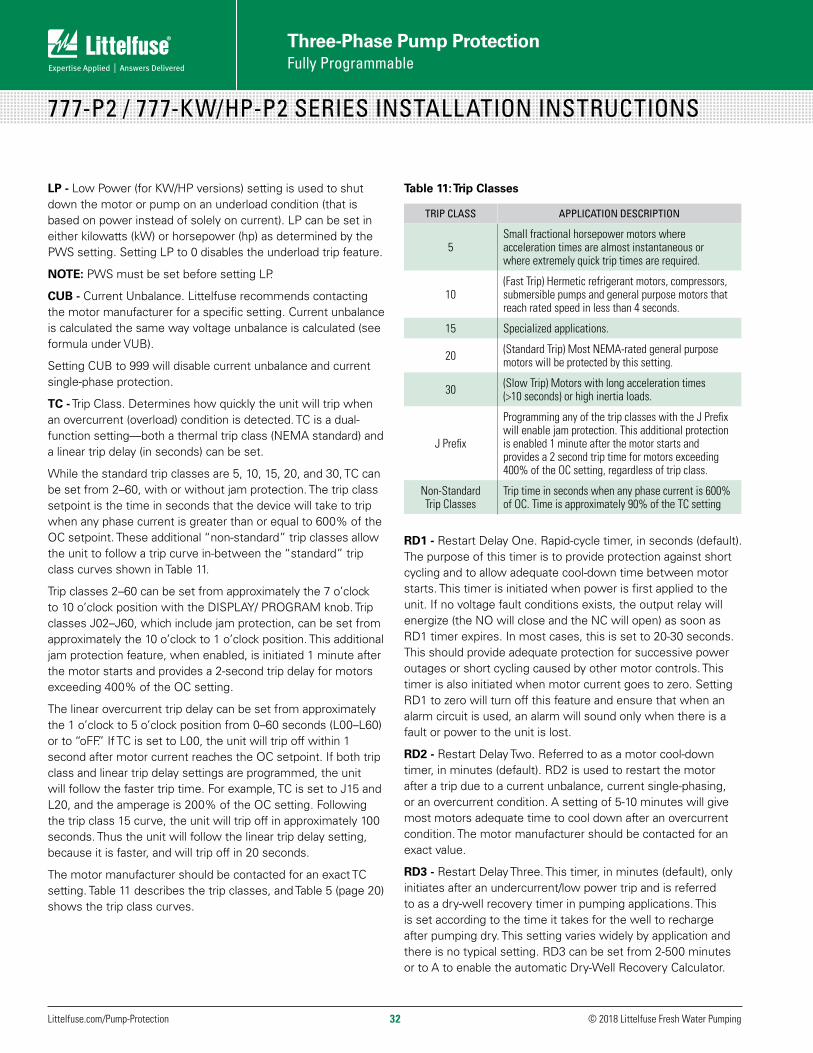
© 2018 Littelfuse Fresh Water Pumping Littelfuse.com/Pump-Protection 32
Three-Phase Pump Protection Fully Programmable
777-P2 / 777-KW/HP-P2 SERIES INSTALLATION INSTRUCTIONS
LP - Low Power (for KW/HP versions) setting is used to shut down the motor or pump on an underload condition (that is based on power instead of solely on current). LP can be set in either kilowatts (kW) or horsepower (hp) as determined by the PWS setting. Setting LP to 0 disables the underload trip feature.
NOTE: PWS must be set before setting LP.
CUB - Current Unbalance. Littelfuse recommends contacting the motor manufacturer for a specific setting. Current unbalance is calculated the same way voltage unbalance is calculated (see formula under VUB).
Setting CUB to 999 will disable current unbalance and current single-phase protection.
TC - Trip Class. Determines how quickly the unit will trip when an overcurrent (overload) condition is detected. TC is a dual-function setting—both a thermal trip class (NEMA standard) and a linear trip delay (in seconds) can be set.
While the standard trip classes are 5, 10, 15, 20, and 30, TC can be set from 2–60, with or without jam protection. The trip class setpoint is the time in seconds that the device will take to trip when any phase current is greater than or equal to 600% of the OC setpoint. These additional “non-standard” trip classes allow the unit to follow a trip curve in-between the “standard” trip class curves shown in Table 11.
Trip classes 2–60 can be set from approximately the 7 o’clock to 10 o’clock position with the DISPLAY/ PROGRAM knob. Trip classes J02–J60, which include jam protection, can be set from approximately the 10 o’clock to 1 o’clock position. This additional jam protection feature, when enabled, is initiated 1 minute after the motor starts and provides a 2-second trip delay for motors exceeding 400% of the OC setting.
The linear overcurrent trip delay can be set from approximately the 1 o’clock to 5 o’clock position from 0–60 seconds (L00–L60) or to “oFF.” If TC is set to L00, the unit will trip off within 1 second after motor current reaches the OC setpoint. If both trip class and linear trip delay settings are programmed, the unit will follow the faster trip time. For example, TC is set to J15 and L20, and the amperage is 200% of the OC setting. Following the trip class 15 curve, the unit will trip off in approximately 100 seconds. Thus the unit will follow the linear trip delay setting, because it is faster, and will trip off in 20 seconds.
The motor manufacturer should be contacted for an exact TC setting. Table 11 describes the trip classes, and Table 5 (page 20) shows the trip class curves.
Table 11: Trip Classes
TRIP CLASS APPLICATION DESCRIPTION
5Small fractional horsepower motors where acceleration times are almost instantaneous or where extremely quick trip times are required.
10(Fast Trip) Hermetic refrigerant motors, compressors, submersible pumps and general purpose motors that reach rated speed in less than 4 seconds.
15 Specialized applications.
20 (Standard Trip) Most NEMA-rated general purpose motors will be protected by this setting.
30 (Slow Trip) Motors with long acceleration times (>10 seconds) or high inertia loads.
J Prefix
Programming any of the trip classes with the J Prefix will enable jam protection. This additional protection is enabled 1 minute after the motor starts and provides a 2 second trip time for motors exceeding 400% of the OC setting, regardless of trip class.
Non-Standard Trip Classes
Trip time in seconds when any phase current is 600% of OC. Time is approximately 90% of the TC setting
RD1 - Restart Delay One. Rapid-cycle timer, in seconds (default). The purpose of this timer is to provide protection against short cycling and to allow adequate cool-down time between motor starts. This timer is initiated when power is first applied to the unit. If no voltage fault conditions exists, the output relay will energize (the NO will close and the NC will open) as soon as RD1 timer expires. In most cases, this is set to 20-30 seconds. This should provide adequate protection for successive power outages or short cycling caused by other motor controls. This timer is also initiated when motor current goes to zero. Setting RD1 to zero will turn off this feature and ensure that when an alarm circuit is used, an alarm will sound only when there is a fault or power to the unit is lost.
RD2 - Restart Delay Two. Referred to as a motor cool-down timer, in minutes (default). RD2 is used to restart the motor after a trip due to a current unbalance, current single-phasing, or an overcurrent condition. A setting of 5-10 minutes will give most motors adequate time to cool down after an overcurrent condition. The motor manufacturer should be contacted for an exact value.
RD3 - Restart Delay Three. This timer, in minutes (default), only initiates after an undercurrent/low power trip and is referred to as a dry-well recovery timer in pumping applications. This is set according to the time it takes for the well to recharge after pumping dry. This setting varies widely by application and there is no typical setting. RD3 can be set from 2-500 minutes or to A to enable the automatic Dry-Well Recovery Calculator.
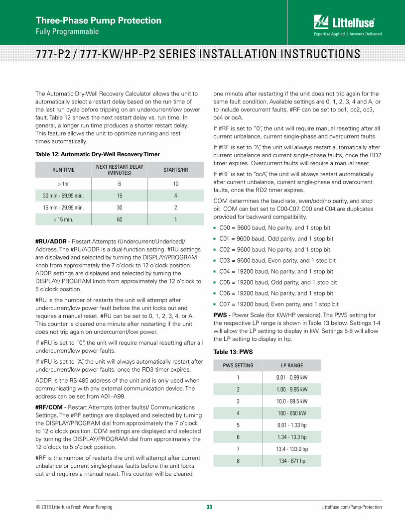
33© 2018 Littelfuse Fresh Water Pumping Littelfuse.com/Pump-Protection33
Three-Phase Pump Protection Fully Programmable
777-P2 / 777-KW/HP-P2 SERIES INSTALLATION INSTRUCTIONS
The Automatic Dry-Well Recovery Calculator allows the unit to automatically select a restart delay based on the run time of the last run cycle before tripping on an undercurrent/low power fault. Table 12 shows the next restart delay vs. run time. In general, a longer run time produces a shorter restart delay. This feature allows the unit to optimize running and rest times automatically.
Table 12: Automatic Dry-Well Recovery Timer
RUN TIME NEXT RESTART DELAY (MINUTES) STARTS/HR
> 1hr 6 10
30 min.- 59.99 min. 15 4
15 min.- 29.99 min. 30 2
< 15 min. 60 1
#RU/ADDR - Restart Attempts (Undercurrent/Underload)/Address. The #RU/ADDR is a dual-function setting. #RU settings are displayed and selected by turning the DISPLAY/PROGRAM knob from approximately the 7 o’clock to 12 o’clock position. ADDR settings are displayed and selected by turning the DISPLAY/ PROGRAM knob from approximately the 12 o’clock to 5 o’clock position.
#RU is the number of restarts the unit will attempt after undercurrent/low power fault before the unit locks out and requires a manual reset. #RU can be set to 0, 1, 2, 3, 4, or A. This counter is cleared one minute after restarting if the unit does not trip again on undercurrent/low power.
If #RU is set to “0”, the unit will require manual resetting after all undercurrent/low power faults.
If #RU is set to “A”, the unit will always automatically restart after undercurrent/low power faults, once the RD3 timer expires.
ADDR is the RS-485 address of the unit and is only used when communicating with any external communication device. The address can be set from A01–A99.
#RF/COM - Restart Attempts (other faults)/ Communications Settings. The #RF settings are displayed and selected by turning the DISPLAY/PROGRAM dial from approximately the 7 o’clock to 12 o’clock position. COM settings are displayed and selected by turning the DISPLAY/PROGRAM dial from approximately the 12 o’clock to 5 o’clock position.
#RF is the number of restarts the unit will attempt after current unbalance or current single-phase faults before the unit locks out and requires a manual reset. This counter will be cleared
one minute after restarting if the unit does not trip again for the same fault condition. Available settings are 0, 1, 2, 3, 4 and A, or to include overcurrent faults, #RF can be set to oc1, oc2, oc3, oc4 or ocA.
If #RF is set to “0”, the unit will require manual resetting after all current unbalance, current single-phase and overcurrent faults.
If #RF is set to “A”, the unit will always restart automatically after current unbalance and current single-phase faults, once the RD2 timer expires. Overcurrent faults will require a manual reset.
If #RF is set to “ocA”, the unit will always restart automatically after current unbalance, current single-phase and overcurrent faults, once the RD2 timer expires.
COM determines the baud rate, even/odd/no parity, and stop bit. COM can bet set to C00-C07. C00 and C04 are duplicates provided for backward compatibility.
JJ C00 = 9600 baud, No parity, and 1 stop bit
JJ C01 = 9600 baud, Odd parity, and 1 stop bit
JJ C02 = 9600 baud, No parity, and 1 stop bit
JJ C03 = 9600 baud, Even parity, and 1 stop bit
JJ C04 = 19200 baud, No parity, and 1 stop bit
JJ C05 = 19200 baud, Odd parity, and 1 stop bit
JJ C06 = 19200 baud, No parity, and 1 stop bit
JJ C07 = 19200 baud, Even parity, and 1 stop bit
PWS - Power Scale (for KW/HP versions). The PWS setting for the respective LP range is shown in Table 13 below. Settings 1-4 will allow the LP setting to display in kW. Settings 5-8 will allow the LP setting to display in hp.
Table 13: PWS
PWS SETTING LP RANGE
1 0.01 - 0.99 kW
2 1.00 - 9.95 kW
3 10.0 - 99.5 kW
4 100 - 650 kW
5 0.01 - 1.33 hp
6 1.34 - 13.3 hp
7 13.4 - 133.0 hp
8 134 - 871 hp
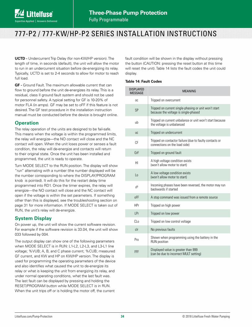
© 2018 Littelfuse Fresh Water Pumping Littelfuse.com/Pump-Protection 34
Three-Phase Pump Protection Fully Programmable
777-P2 / 777-KW/HP-P2 SERIES INSTALLATION INSTRUCTIONS
UCTD - Undercurrent Trip Delay (for non-KW/HP version). The length of time, in seconds (default), the unit will allow the motor to run in an undercurrent situation before de-energizing its relay. Typically, UCTD is set to 2-4 seconds to allow for motor to reach full load.
GF - Ground Fault. The maximum allowable current that can flow to ground before the unit de-energizes its relay. This is a residual, class II ground fault system and should not be used for personnel safety. A typical setting for GF is 10-20% of motor FLA (in amps). GF may be set to oFF if this feature is not desired. The GF test procedure in the installation instruction manual must be conducted before the device is brought online.
OperationThe relay operation of the units are designed to be fail-safe. This means when the voltage is within the programmed limits, the relay will energize—the NO contact will close and the NC contact will open. When the unit loses power or senses a fault condition, the relay will de-energize and contacts will return to their original state. Once the unit has been installed and programmed, the unit is ready to operate.
Turn MODE SELECT to the RUN position. The display will show “run” alternating with a number (the number displayed will be the number corresponding to where the DISPLAY/PROGRAM knob is pointed). It will do this for the restart delay time programmed into RD1. Once the timer expires, the relay will energize—the NO contact will close and the NC contact will open if the voltage is within the set parameters. If something other than this is displayed, see the troubleshooting section on page 31 for more information. If MODE SELECT is taken out of RUN, the unit’s relay will de-energize.
System DisplayOn power up, the unit will show the current software revision. For example if the software revision is 33.04, the unit will show 033 followed by 004.
The output display can show one of the following parameters when MODE SELECT is in RUN: L1-L2, L2-L3, and L3-L1 line voltage; %VUB; A, B, and C phase current; %CUB; measured GF current, and KW and HP on KW/HP version. The display is used for programming the operating parameters of the device and also identifies what caused the unit to de-energize its relay or what is keeping the unit from energizing its relay, and under normal operating conditions, what the last fault was. The last fault can be displayed by pressing and holding the RESET/PROGRAM button while MODE SELECT is in RUN. When the unit trips off or is holding the motor off, the current
fault condition will be shown in the display without pressing the button (CAUTION: pressing the reset button at this time will reset the unit). Table 14 lists the fault codes the unit could display.
Table 14: Fault Codes
DISPLAYED MESSAGE MEANING
oc Tripped on overcurrent
SP Tripped on current single-phasing or unit won’t start because the voltage is single-phased
ub Tripped on current unbalance or unit won’t start because the voltage is unbalanced
uc Tripped on undercurrent
CF Tripped on contactor failure (due to faulty contacts or connections on the load side)
GrF Tripped on ground fault
HI A high voltage condition exists (won’t allow motor to start)
Lo A low voltage condition exists (won’t allow motor to start)
rP Incoming phases have been reversed, the motor may run backwards if started
oFF A stop command was issued from a remote source
HPr Tripped on high power
LPr Tripped on low power
CLo Tripped on low control voltage
clr No previous faults
Pro Shown when programming using the battery in the RUN position
FFF Displayed value is greater than 999 (can be due to incorrect MULT setting)

35© 2018 Littelfuse Fresh Water Pumping Littelfuse.com/Pump-Protection35
Three-Phase Pump Protection Fully Programmable
777-P2 / 777-KW/HP-P2 SERIES INSTALLATION INSTRUCTIONS
Table 15: Troubleshooting Chart
PROBLEM SOLUTION
The unit will not start. Display alternates “rP” with the DISPLAY/PROGRAM parameter value.
The voltage inputs are reverse-phased. If this is the initial start-up, swap any two of the leads connected to L1, L2, or L3 on the unit to correct the problem. If the unit has been previously running, the power system has been reverse-phased. Check the phase sequence of the incoming power lines. Note: L1 must be tapped from conductor Phase A, L2 from B, and L3 from C for correct power factor measurements on remote communications.
The unit will not start. Display alternates “SP”, “ub”, “HI”, or “Lo” with the DISPLAY/PROGRAM parameter value.
The incoming voltage is not within the limits programmed in the VUB,HV, and LV settings. Turn the DISPLAY/PROGRAM knob to read each incoming line voltage value. Correct the incoming power problem and check programmed limits by turning the MODE SELECT knob. Compare incoming values for HV, LV, and VUB to setpoints to verify they are correct.
Display alternates “SP”, “ub”, or “oc” with “run”
The unit has tripped on the fault shown on the display and is timing down RD2 before restarting. No further action is required.
Display alternates “uc” with “run”The unit has tripped on undercurrent and is counting down RD3 before restarting. If undercurrent is not a normal condition for this application, check for broken shafts, belts, or closed valves or loss of liquid.
Display is showing a solid “SP”, “ub”, or “oc”
The unit has tripped on the fault shown and a manual reset is required because of the programmed setting in #RF. Check the system for problems that would produce the single-phase, overcurrent or current unbalance fault, such as a jam.
Display is showing a solid “uc”The unit has tripped on undercurrent and a manual reset is required because of the setting in #RU. Check the system for problems that would produce an undercurrent condition like a dead-head or a lack of liquid to the pump.
Display is showing a solid “CF”The unit has tripped on current single-phasing, but was not single-phased by the incoming voltage. Check for damaged contacts or loose or corroded wiring connections.
Display is showing a solid “GrF”A ground fault current greater than the programmed GF value has been detected. Check the motor for insulation breakdown. A manual reset is required to clear this message. Press the RESET/PROGRAM button to perform a manual reset.
Display alternates “LPr” with “RUN”The unit has tripped on low power (LPr) and is timing down RD3 before restarting. If LPr is not a normal condition for this application, check for broken shafts, belts, or closed valves or loss of liquid.
Display is showing a solid “LPr”The unit has tripped on low power and a manual reset is required because of the setting in #RU. Check the system for problems that would produce a loss of load or a pump is out of liquid. Press the RESET/PROGRAM button to perform a manual reset.
Display alternates “HPr” with “RUN” The unit has tripped on high power and is timing down RD2. Check for a high power condition.
Display is showing solid “HPr”The unit has tripped on high power and requires a manual reset because of the setting in #RF. Press the RESET/PROGRAM button to perform a manual reset.
Display alternates “CLo” with “RUN” The unit has tripped on low control voltage (CLo) and is timing down RD2 before restarting.
Display is showing solid “CLo”The unit has tripped on low control voltage (CLo) and a manual reset is required because of the setting in #RF. Verify system voltage is correct. Press the RESET/PROGRAM button to perform a manual reset.
TROUBLESHOOTINGThe unit will display a fault code alternating with a number or with “run” when it has tripped. If the unit is showing a fault code alternating with “run,” it is timing down the restart delay. If the fault code is alternating with a number (voltage reading or zero), the unit will not allow the motor to start because there is a
problem with the incoming voltage. If the display is showing just a fault code, the unit is in a manual reset mode. This could be because the number of restarts (#RF, #RU) has expired or is not allowed. If the display reads “oFF,” a stop command was issued through the communications network or a remote monitor.
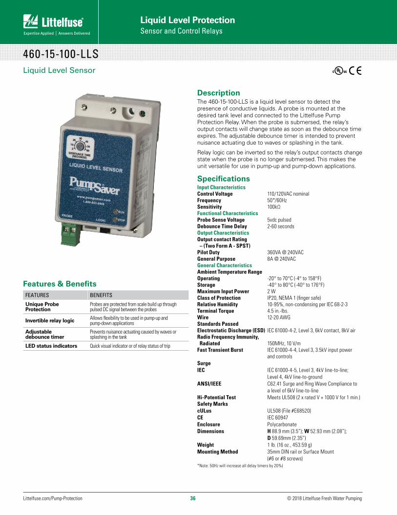
© 2018 Littelfuse Fresh Water Pumping Littelfuse.com/Pump-Protection 36
Liquid Level Protection Sensor and Control Relays
460-15-100-LLSLiquid Level Sensor
DescriptionThe 460-15-100-LLS is a liquid level sensor to detect the presence of conductive liquids. A probe is mounted at the desired tank level and connected to the Littelfuse Pump Protection Relay. When the probe is submersed, the relay’s output contacts will change state as soon as the debounce time expires. The adjustable debounce timer is intended to prevent nuisance actuating due to waves or splashing in the tank.
Relay logic can be inverted so the relay’s output contacts change state when the probe is no longer submersed. This makes the unit versatile for use in pump-up and pump-down applications.
Specifications Input CharacteristicsControl Voltage 110/120VAC nominalFrequency 50*/60Hz Sensitivity 100kΩFunctional CharacteristicsProbe Sense Voltage 5vdc pulsedDebounce Time Delay 2-60 secondsOutput CharacteristicsOutput contact Rating – (Two Form A - SPST) Pilot Duty 360VA @ 240VAC General Purpose 8A @ 240VAC General CharacteristicsAmbient Temperature RangeOperating -20° to 70°C (-4° to 158°F) Storage -40° to 80°C (-40° to 176°F) Maximum Input Power 2 W Class of Protection IP20, NEMA 1 (finger safe) Relative Humidity 10-95%, non-condensing per IEC 68-2-3Terminal Torque 4.5 in.-lbs. Wire 12-20 AWG Standards Passed Electrostatic Discharge (ESD) IEC 61000-4-2, Level 3, 6kV contact, 8kV air Radio Frequency Immunity, Radiated 150MHz, 10 V/m Fast Transient Burst IEC 61000-4-4, Level 3, 3.5kV input power and controls Surge IEC IEC 61000-4-5, Level 3, 4kV line-to-line; Level 4, 4kV line-to-ground ANSI/IEEE C62.41 Surge and Ring Wave Compliance to a level of 6kV line-to-line Hi-Potential Test Meets UL508 (2 x rated V + 1000 V for 1 min.) Safety Marks cULus UL508 (File #E68520)CE IEC 60947Enclosure Polycarbonate Dimensions H 88.9 mm (3.5”); W 52.93 mm (2.08”); D 59.69mm (2.35”) Weight 1 lb. (16 oz., 453.59 g)Mounting Method 35mm DIN rail or Surface Mount (#6 or #8 screws)*Note: 50Hz will increase all delay timers by 20%)
Features & BenefitsFEATURES BENEFITS
Unique Probe Protection
Probes are protected from scale build up through pulsed DC signal between the probes
Invertible relay logic Allows flexibility to be used in pump-up and pump-down applications
Adjustable debounce timer
Prevents nuisance actuating caused by waves or splashing in the tank
LED status indicators Quick visual indicator or of relay status of trip
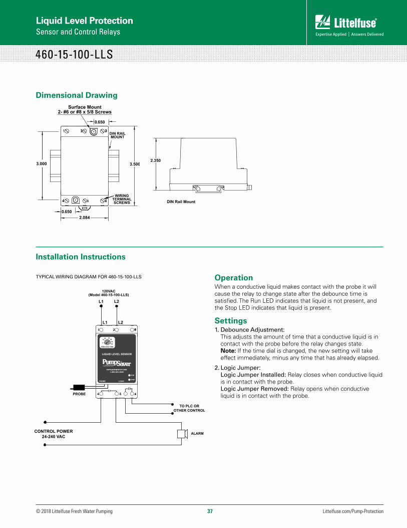
© 2018 Littelfuse Fresh Water Pumping Littelfuse.com/Pump-Protection37
460-15-100-LLS
Dimensional Drawing
460-15-100-LLS - DIMENSIONS
2.350
DIN Rail Mount
Installation Instructions
TYPICAL WIRING DIAGRAM FOR 460-15-100-LLS OperationWhen a conductive liquid makes contact with the probe it will cause the relay to change state after the debounce time is satisfied. The Run LED indicates that liquid is not present, and the Stop LED indicates that liquid is present.
Settings1. Debounce Adjustment:
This adjusts the amount of time that a conductive liquid is in contact with the probe before the relay changes state. Note: If the time dial is changed, the new setting will take effect immediately, minus any time that has already elapsed.
2. Logic Jumper: Logic Jumper Installed: Relay closes when conductive liquid is in contact with the probe. Logic Jumper Removed: Relay opens when conductive liquid is in contact with the probe.
Liquid Level ProtectionSensor and Control Relays

© 2018 Littelfuse Fresh Water Pumping Littelfuse.com/Pump-Protection 38
Liquid Level Protection Sensor and Control Relays
PC-XXX-LLC-CZ / PC-XXX-LLC-GM SERIESLiquid Level Control Relays
DescriptionThe PC-XXX-LLC-CZ & PC-XXX-LLC-GM are liquid level control relays used to control conductive liquid pumping operations in a pump-up or pump-down application. The units come in two different voltage ranges (see specs on adjacent page).
The units have an adjustable sensitivity knob (4.7k to 100k ohms) that is set according to the resistance level at which you want the (user supplied) probes to sense the conductive liquid. The units have a built-in debounce time delay that prevents the relay from energizing if the probe resistance momentarily goes above or below the sensitivity setpoint (due to liquid splashing in the tank).
The units operate their internal relay based on inputs from a high and low probe and a common reference (when a conductive tank is used) or common probe (when a non-conductive tank is used).
PC-XXX-LLC-CZJJ Compatible with Crouzet’s PNR & PNRU series liquid
level control
(Direct replacement for Crouzet models: PNR110A, PNR220A, PNRU110A, PNRU220A)
PC-XXX-LLC-GMJJ Compatible with Gems’ Series 16M general purpose control
(Direct replacement for GEMS models: 16MA1A0, 16MB1A0, 16MC1A0, 16MD1A0, 16ME1A0, 16MA2A0, 16MB2A0, 16MC2A0, 16MD2A0, 16ME2A0, 16MK1A0, 16ML1A0, 16MM1A0, 16MN1A0, 16MP1A0, 16MK2A0, 16MM2A0, 16MN2A0, 16MP2A0)
Must use Model OT08-PC socket for UL Rating!
Note: Manufacturer’s recommended screw terminal torque for the OT Series Octal Sockets is 12 in.-lbs.
Accessories8-pin Octal Socket (P/N: OT08-PC) Octal Socket for plug-in units. 8-pin surface & DIN rail mountable
MODEL LINE VOLTAGE DESCRIPTION
PC-100-LLC-CZ 95 to 120VAC Compatible with Crouzet PNR & PNRU series
PC-200-LLC-CZ 190 to 240VAC Compatible with Crouzet PNR & PNRU series
PC-100-LLC-GM 95 to 120VAC Compatible with Gems’ series 16M
PC-200-LLC-GM 190 to 240VAC Compatible with Gems’ series 16M
Ordering Information

© 2018 Littelfuse Fresh Water Pumping Littelfuse.com/Pump-Protection39
PC-XXX-LLC-CZ / PC-XXX-LLC-GM SERIES
SpecificationsInput CharacteristicsSupply Voltage:PC-100-LLC-CZ 95-120VACPC-100-LLC-GM 95-120VACPC-200-LLC-CZ 190-240VACPC-200-LLC-GM 190-240VACFrequency 50/60HzFunctional CharacteristicsProbe Sense Voltage 5vdc pulsedDebounce Time Delay 2 secondsProbe Sensitivity 4.7k to 100k AdjustableOutput CharacteristicsOutput Contact Rating:Pilot Duty 480VA @ 240VACGeneral Purpose 10A @240VACGeneral CharacteristicsTemperature Range -40° to 70°C (-40° to 158°F)Maximum Input Power 5 WStandards PassedElectrostatic Discharge (ESD) IEC 61000-4-2, Level 3, 6kV contact, 8kV air.Radio Frequency Immunity (RFI) 150MHz, 10V/mFast Transients IEC 61000-4-4, Level 3, 2kV input power and controls Safety MarkscULus (OT08-PC octal socket required) UL508 (File #E68520)CE IEC60947-6-2Dimensions (when installed in socket base) H 44.45 mm (1.75”); W 60.33 mm (2.375”); D 104.78 mm (4.125”) Weight 0.65 lb. (10.4 oz., 294.84 g)Mounting Method DIN rail or surface mount (plug into OT08-PC socket) Socket Available Model OT08-PC (UL Rating 600V)
The 600V socket can be surface mounted or installed on DIN Rail.
BOTTOM
2.375[60.331]
1.75[44.45]
SIDE
3.15[80.01]
0.5[12.7]
inches [millimeters]
Dimensional Drawing
Liquid Level ProtectionSensor and Control Relays
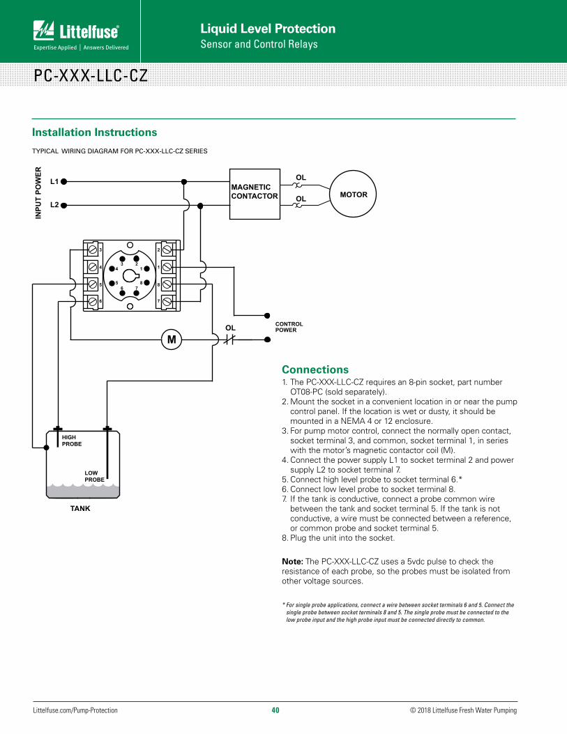
Liquid Level Protection Sensor and Control Relays
© 2018 Littelfuse Fresh Water Pumping Littelfuse.com/Pump-Protection 40
PC-XXX-LLC-CZ
Connections1. The PC-XXX-LLC-CZ requires an 8-pin socket, part number
OT08-PC (sold separately).2. Mount the socket in a convenient location in or near the pump
control panel. If the location is wet or dusty, it should be mounted in a NEMA 4 or 12 enclosure.
3. For pump motor control, connect the normally open contact, socket terminal 3, and common, socket terminal 1, in series with the motor’s magnetic contactor coil (M).
4. Connect the power supply L1 to socket terminal 2 and power supply L2 to socket terminal 7.
5. Connect high level probe to socket terminal 6.*6. Connect low level probe to socket terminal 8.7. If the tank is conductive, connect a probe common wire
between the tank and socket terminal 5. If the tank is not conductive, a wire must be connected between a reference, or common probe and socket terminal 5.
8. Plug the unit into the socket.
Note: The PC-XXX-LLC-CZ uses a 5vdc pulse to check the resistance of each probe, so the probes must be isolated from other voltage sources.
* For single probe applications, connect a wire between socket terminals 6 and 5. Connect the single probe between socket terminals 8 and 5. The single probe must be connected to the low probe input and the high probe input must be connected directly to common.
Installation Instructions TYPICAL WIRING DIAGRAM FOR PC-XXX-LLC-CZ SERIES

© 2018 Littelfuse Fresh Water Pumping Littelfuse.com/Pump-Protection41
Liquid Level ProtectionSensor and Control Relays
PC-XXX-LLC-GM
Connections1. The PC-XXX-LLC-GM requires an 8-pin socket, part number
OT08-PC (sold separately).2. Mount the socket in a convenient location in or near the pump
control panel. If the location is wet or dusty, it should be mounted in a NEMA 4 or 12 enclosure.
3. For pump motor control, connect the normally open contact, socket terminal 6, and common, socket terminal 8, in series with the motor’s magnetic contactor coil (M).
4. Connect the power supply L1 to socket terminal 1 and power supply L2 to socket terminal 2.
5. Connect high level probe to socket terminal 3.*6. Connect low level probe to socket terminal 4.7. If the tank is conductive, connect a probe common wire
between the tank and socket terminal 5. If the tank is not conductive, a wire must be connected between a reference, or common, probe and socket terminal 5.
8. Plug the unit into the socket.
Note: The PC-XXX-LLC-GM uses a 5vdc pulse to check the resistance of each probe, so the probes must be isolated from other voltage sources.
* For single probe applications, connect the single probe between socket terminals 3 and 5. The single probe must be connected to the high probe input and the low probe input must be left open.
Installation Instructions TYPICAL WIRING DIAGRAM FOR PC-XXX-LLC-GM SERIES
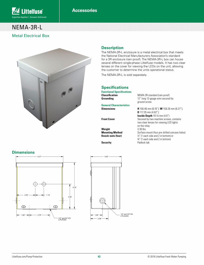
© 2018 Littelfuse Fresh Water Pumping Littelfuse.com/Pump-Protection 42
Accessories
Dimensions6.27”
6.16”
1.69”
3.30”2.50” 1.13”
2.75”
1/2" and 3/4" KO2 PLACES
4.62”
2.38”
1.59” 2 PLACES1/2" and 3/4" KO
NEMA-3R-L
DescriptionThe NEMA-3R-L enclosure is a metal electrical box that meets the National Electrical Manufacturers Association’s standard for a 3R enclosure (rain proof). The NEMA-3R-L box can house several different single-phase Littelfuse models. It has two clear lenses on the cover for viewing the LEDs on the unit, allowing the customer to determine the units operational status.
The NEMA-3R-L is sold separately.
SpecificationsFunctional SpecificationsClassification NEMA 3R standard (rain proof)Grounding 12” long 12-gauge wire secured by ground screwGeneral CharacteristicsDimensions H 156.46 mm (6.16”); W 159.26 mm (6.27”); D 117.35 mm (4.62”); Inside Depth 101.6 mm (4.0”)Front Cover Secured by two machine screws, contains two clear lenses for viewing LED lights on the relayWeight 3.30 lbs.Mounting Method Surface mount (four pre-drilled concave holes)Knock-outs (four) ½” (1 each side and 2 in bottom) or ¾” (1 each side and 2 in bottom)Security Padlock tab
NEMA-3R-LMetal Electrical Box
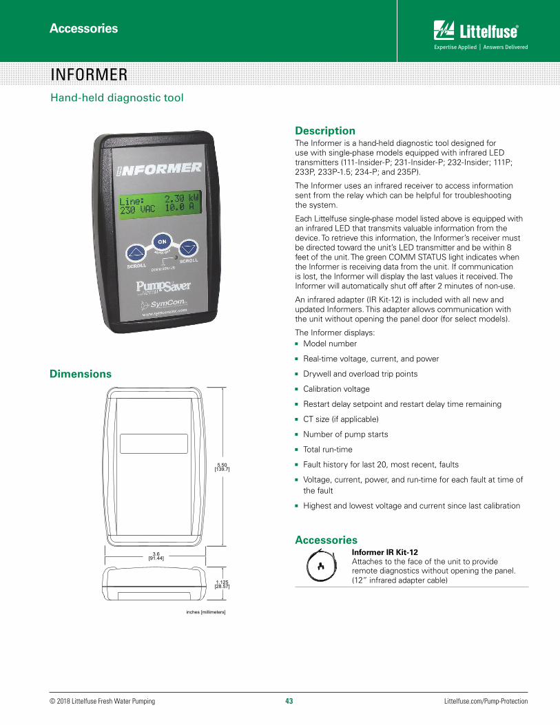
© 2018 Littelfuse Fresh Water Pumping Littelfuse.com/Pump-Protection43
Accessories
INFORMERHand-held diagnostic tool
Description The Informer is a hand-held diagnostic tool designed for use with single-phase models equipped with infrared LED transmitters (111-Insider-P; 231-Insider-P; 232-Insider; 111P; 233P, 233P-1.5; 234-P; and 235P).
The Informer uses an infrared receiver to access information sent from the relay which can be helpful for troubleshooting the system.
Each Littelfuse single-phase model listed above is equipped with an infrared LED that transmits valuable information from the device. To retrieve this information, the Informer’s receiver must be directed toward the unit’s LED transmitter and be within 8 feet of the unit. The green COMM STATUS light indicates when the Informer is receiving data from the unit. If communication is lost, the Informer will display the last values it received. The Informer will automatically shut off after 2 minutes of non-use.
An infrared adapter (IR Kit-12) is included with all new and updated Informers. This adapter allows communication with the unit without opening the panel door (for select models).
The Informer displays:JJ Model number
JJ Real-time voltage, current, and power
JJ Drywell and overload trip points
JJ Calibration voltage
JJ Restart delay setpoint and restart delay time remaining
JJ CT size (if applicable)
JJ Number of pump starts
JJ Total run-time
JJ Fault history for last 20, most recent, faults
JJ Voltage, current, power, and run-time for each fault at time of the fault
JJ Highest and lowest voltage and current since last calibration
AccessoriesInformer IR Kit-12Attaches to the face of the unit to provide remote diagnostics without opening the panel. (12” infrared adapter cable)
Dimensions

Accessories
© 2018 Littelfuse Fresh Water Pumping Littelfuse.com/Pump-Protection 44
INFORMER
SpecificationsFunctional CharacteristicsPowerInput 9 Volts DC (requires one 9-volt alkaline battery)Auto Shut-off 2 minutesCommunicationSignal InfraredRange 1-8 ft. (approx. 0.25 ft. when using IR Kit)Data Update 4 secondsGeneral CharacteristicsTemperature Range 0 to 60°C (32° to 140°F)AccuracyVoltage ± 2%Current ± 2% Power ± 4% Maximum Input 0.25 WResolutionVoltage 1.0VACDisplay Liquid crystalSize 2 rows x 16 charactersKeypad Three 0.5” diameter buttons Mechanical Life 100,000 actuations min.Overlay Material Polyester EnclosureDimensions H 139.70 mm (5.50”); W 91.44 mm (3.60”); D 28.70 mm (1.13”)Weight 0.375 lb. (6 oz., 170.10 g) (w/out battery); 0.70 lb. (11.2 oz., 317.51 g) (total package) Material Black ABS 94HB
Troubleshooting GuidePROBLEM SOLUTION
The Informer does not activate when the ON button is pressed.
Battery Polarity Reversed – Verify the + and – terminals on the battery match the markings inside the battery compartment.
Low Battery – Replace the battery.
The COMM STATUS light is off and all display values remain at zero.
Weak Signal – Ensure the Informer is aimed directly at the unit’s infrared LED and is within the operating distance.
Unit Not Transmitting – Verify the unit is energized and the green RUN light is illuminated.
Sunlight - Verify the sun is not shining directly onto the Informer’s infrared receiver or the unit’s infrared LED.
The COMM STATUS light is blinking.
Weak Signal – Ensure the Informer is aimed directly at the unit’s infrared LED and is within the operating distance.
If using an older Informer (version 1.XX or earlier), this is a normal condition.
The displayed values fluctuate radically.
Weak Signal – Ensure the Informer is aimed directly at the unit’s infrared LED and is within the operating distance.
The Informer displays values even after communication is lost.
This is Normal – The Informer holds the last values it received before communication was lost (until the auto shut off).

WWW.LITTELFUSE.COM/RELAYSCONTROLS
Littelfuse’s staff of professional engineers assists customers with the application of protection relays. By working with the customer during the design phase, our engineers are able to help identify potential issues and provide product recommendations to resolve difficult problems. Since we are involved from the beginning, we are also able to provide recommendations for relay settings.
Our experienced product and application engineers are available to provide assistance when investigating the cause of a relay trip, or assisting with product setup. As systems grow in terms of power and physical size, some products and settings may need to be adjusted. If so, our engineers are available to answer any questions that arise when modifying these applications.
Featuring easy to use navigation, search and selection tools as well as in-depth product details, Littelfuse.com/RelaysControls is a powerful resource for up-to-date technical information. In addition, our website features various software applications, such as relay-to-PC interface software, firmware, upgrade software, online demos and programming tutorials.
Application Support
Field Support
Online Tools and Relay Software
Let Us Help You Build a Safe Electrical System
Contact our protection relay and safety experts today at 1-800-832-3873 or [email protected] to find out what Littelfuse can do for you.

Kaunas
Amsterdam
Muzquiz
Bellingham
Matamoros
Boston
EssenSaskatoon
Piedras Negras
SeoulTokyoTsukuba
SuzhouWuxi
Beijing
ShanghaiKunshan
TaipeiChu-pei
DongguanShenzhen
Hong Kong
Lipa City
Singapore
São Paulo
Legnago
BremenDeventer
LaufOzegna
Troy
Eagle Pass
Manaus
Lake MillsRapid CityChicago
ChampaignFreemont
Local Resources for a GLOBAL Market
To view all Littelfuse product catalogs, visit our website at Littelfuse.com/Catalogs. Go to Littelfuse.com/TechnicalResources
Protection Relays & Controls Catalog The comprehensive line of electronic and microprocessor-based protection relays safeguard equipment and personnel to prevent expensive damage, downtime or injury due to electrical faults.
Visit Technical Resources at Littelfuse.com Technical information is only a click away. The Littelfuse Technical Resources contains datasheets, product manuals, white papers, application guides, demos, on-line design tools, and more.
Fuses and Fuse Holders Catalog Littelfuse offers a complete circuit protection portfolio of industrial power fuses, including time-saving indication products for an instant visual blown-fuse identification.
Littelfuse products are certified to many standards around the world. To check certifications on specific product please refer to the product datasheet on Littelfuse.com.
Littelfuse World Headquarters8755 West Higgins Road, Suite 500Chicago, IL 60631, USATechnical Support: Tel: +1-800-TEC-FUSEE-mail: [email protected] Customer Service:Tel: +1-800-227-0029E-mail: [email protected]: +1-847-787-5190
Littelfuse SymCom222 Disk DriveRapid City, SD 57701, USATechnical Support:Tel: +1-800-832-3873E-mail: [email protected] Customer Service: Tel: +1-800-227-0029E-mail: [email protected]: + 1-605-348-5685
Littelfuse Startco3714 Kinnear PlaceSaskatoon, SK S7P 0A6CanadaTel: +1-306-373-5505Fax: +1-306-374-2245E-mail: [email protected]
© 2018 Littelfuse, Inc.FORM PF156
Rev: 1-C-010918
Disclaimer Notice – Information furnished is believed to be accurate and reliable. However, users should independently evaluate the suitability of and test each product selected for their own applications. Littelfuse products are not designed for, and may not be used in, all applications. Read complete Disclaimer Notice at www.littelfuse.com/product-disclaimer.


