44th International Conference on Environmental Systems ICES-2014-106 13-17 July 2014, Tucson, Arizona Fresnel-based Solar Concentration Power System for Mars and Lunar Outposts Roberto Furfaro 1 and Sean Gellenbeck. 2 The University of Arizona, Tucson, Arizona, 85721 and Phil Sadler 3 Sadler Machine Company, Tempe, Arizona, USA Future human exploration of the solar system will require architecting and deploying missions that last for years. Oxygen generation and atmosphere revitalization represent a critical component for sustainable long-term space missions. Bioregenerative Life Support Systems (BLSS) can recycle oxygen, water and produce food. However, power is generally a limiting factor for effective implementation of such systems. Nevertheless, solar concentrating technology can be integrated with BLSS to improve performance and reduce the Equivalent System Mass (ESM). In this paper we present and discuss the development of a Fresnel-based Solar Concentration Power System (SCPS) for future Mars and lunar outposts. SCPS is primarily conceived to operate as energy support system for outposts that comprise a greenhouse-based BLSS as source for oxygen, water and food. The system employed a closed-loop sun-tracking system coupled with a Fresnel-based collector capable of separating the solar irradiation as function of wavelength along the system’s longitudinal axis. A set of fiber optics was employed to distribute the Photosynthetic Active Radiation (PAR) portion of the spectrum to the greenhouse components. In addition, the system was designed to collect infra-red portion of the spectrum and convert it to electricity using a set of PV cells. An initial Fresnel-based SCPS prototype was tested and evaluated at the University of Arizona Controlled Environment Agriculture Center. An analysis was conducted to understand the impact of the system performance on the energy balance of future Mars and lunar outposts. Nomenclature ALS = Advanced Life Support BLSS = Bioregenerative Life Support System CWF = Cool White Fluorescence ESM = Equivalent System Mass HPS = High Pressure Sodium IR = Infra-Red KSC = Kennedy Space Center LGH = Lunar Greenhouse NASA = National Air and Space Administration OW = Optical Waveguide PAR = Photosynthetic Active Radiation PPF = Photosynthetic Photon Flux PV = Photovoltaic 1 Assistant Professor, Department of Systems and Industrial Engineering, Department of Aerospace and Mechanical Engineering, University of Arizona, 1127 E James E Rogers Way, Tucson, Arizona, 85721 2 Student Worker, University of Arizona Controlled Environment Agriculture Center, 1951 E Roger Rd., Tucson, Arizona 85719 3 CEO, Sadler Machine Company, Tempe, Arizona, 85281.
Transcript
44th International Conference on Environmental Systems ICES-2014-106 13-17 July 2014, Tucson, Arizona
Fresnel-based Solar Concentration Power System for Mars and Lunar Outposts
Roberto Furfaro1 and Sean Gellenbeck.2
The University of Arizona, Tucson, Arizona, 85721
and
Phil Sadler3 Sadler Machine Company, Tempe, Arizona, USA
Future human exploration of the solar system will require architecting and deploying missions that last for years. Oxygen generation and atmosphere revitalization represent a critical component for sustainable long-term space missions. Bioregenerative Life Support Systems (BLSS) can recycle oxygen, water and produce food. However, power is generally a limiting factor for effective implementation of such systems. Nevertheless, solar concentrating technology can be integrated with BLSS to improve performance and reduce the Equivalent System Mass (ESM). In this paper we present and discuss the development of a Fresnel-based Solar Concentration Power System (SCPS) for future Mars and lunar outposts. SCPS is primarily conceived to operate as energy support system for outposts that comprise a greenhouse-based BLSS as source for oxygen, water and food. The system employed a closed-loop sun-tracking system coupled with a Fresnel-based collector capable of separating the solar irradiation as function of wavelength along the system’s longitudinal axis. A set of fiber optics was employed to distribute the Photosynthetic Active Radiation (PAR) portion of the spectrum to the greenhouse components. In addition, the system was designed to collect infra-red portion of the spectrum and convert it to electricity using a set of PV cells. An initial Fresnel-based SCPS prototype was tested and evaluated at the University of Arizona Controlled Environment Agriculture Center. An analysis was conducted to understand the impact of the system performance on the energy balance of future Mars and lunar outposts.
Nomenclature ALS = Advanced Life Support BLSS = Bioregenerative Life Support System CWF = Cool White Fluorescence ESM = Equivalent System Mass HPS = High Pressure Sodium IR = Infra-Red KSC = Kennedy Space Center LGH = Lunar Greenhouse NASA = National Air and Space Administration OW = Optical Waveguide PAR = Photosynthetic Active Radiation PPF = Photosynthetic Photon Flux PV = Photovoltaic 1 Assistant Professor, Department of Systems and Industrial Engineering, Department of Aerospace and Mechanical Engineering, University of Arizona, 1127 E James E Rogers Way, Tucson, Arizona, 85721 2 Student Worker, University of Arizona Controlled Environment Agriculture Center, 1951 E Roger Rd., Tucson, Arizona 85719 3 CEO, Sadler Machine Company, Tempe, Arizona, 85281.
International Conference on Environmental Systems
2
SC = Solar Collector SCPS = Solar Concentration Power System SICTDS = Solar Irradiation Collection Distribution and Transmission Systems SMC = Sadler Machine Co. UV = Ultraviolet UA-CEAC = University of Arizona Controlled Environment Agriculture Center UA-SIE = University of Arizona Department of Systems and Industrial Engineering
I. Introduction stablishing a continuous human presence on planetary surfaces (e.g. Moon, Mars) requires the design and development of a permanent outpost. Such system must be able to a) provide an initial outpost for the
exploration of geological sites of interest, b) sustain human presence on the planetary surface for extended periods of time, and c) facilitate the development and testing of new approaches and technologies for future lunar/Mars surface systems. Over the past few years Sadler Machine Co. (SMC) in cooperation with the University of Arizona Controlled Environment Agriculture Center (UA-CEAC) and the Department of Systems and Industrial Engineering (UA-SIE) has been developing a novel lunar habitat design that can support the establishment of a lunar outpost (Fig.1, Sadler et. al1). The conceptual lunar habitat is equipped with a Bioregenerative Life Support System (BLSS)2. Although initially conceived as a permanent lunar outpost, the system can be readily adapted to become a Mars permanent outpost. The proposed design is comprised of living systems for human life support, including food crop cultivation and composting, to recycle the air (oxygen-CO2), water, and partially satisfy caloric food requirements. The BLSS is the primary life support system of the proposed lunar habitat, with physicochemical systems as secondary. One of the critical factors for the successful implementation of the proposed BLSS is the greenhouse modules that are employed for crop production (Fig. 2). Indeed, growing plants within an enclosed, fully recycling
controlled environment is crucial for developing BLSS for space applications, including future Moon and Mars human outposts. However, growing plants in BLSS requires extensive use of energy-intensive electric light sources which demands high power consumption (up to 500 W/m2 of electrical power), and heat dissipation of nearly 360 W/m2 (Giacomelli, et al3) Usage of conventional High Pressure Sodium (HPS) and/or Cool White Fluorescence (CWF) lamps translates in up to 66% energy waste due to the inefficiency of the lamps.
Ikeda et. al4 showed that a growth chamber illuminated by a combination of HPS and CWF lamps and designed to sustain a Photosynthetic Photon Flux (PPF) between 330 and 650 𝜇𝑚𝑜𝑙 𝑚−2𝑠−1 for 16 h day-1 absorbed 70% of the total power input. Therefore considering energy convernsion inefficiency, growing plants using direct solar energy would be the most viable option. Using direct solar energy would eliminate energy losses associated with power generation, power conditioning, and electric power to radiation conversion. Solar Irradiation Collection Distribution and Transmission Systems (SICTDS5,6) represent an attractive technology to illuminate plants in BLSS7,8. This technology was based on using a solar collection or concentrator system, coupled with fiber optic cables to collect, transmit and distribute the solar irradiance into the greenhouse of the BLSS, and thereby reduce the
E
A
B
Figure 1. A) Model of the proposed Lunar Habitat (Sadler et. al1) B) HAB top view: four LGH units are highlighted
International Conference on Environmental Systems
3
electrical power demand in a BLSS. Pioneering work on solar collection and distribution via fiber optics has been conducted by Kato and Nakamura9 which led the first theoretical study on the feasibility of transmitting solar radiation within optical fibers. They concluded that it is possible to transmit solar radiation effectively with a fused-silica optical fiber over a distance of approximately 100 m. The first experimental demonstration of such technology was made by Cariou et al11.They demonstrated that the transmission of concentrated solar radiation can be achieved using a simple parabolic mirror and a fused-silica optical fiber. The system had a transport efficiency of about 80% over a 15 m cable. They concluded that it was possible to obtain high density solar energy by increasing the size and/or the number of mirrors, in conjunction
with optical fiber bundles. The NASA Ralph Steckler Space Grant Colonization Research and Technology Development Opportunity Phase
II investigation12 awared a grant to a University of Arizona team to develop a full-scale LGH prototype for lunar outposts. Part of the investigation dealt with the initial developing and study of a Solar Concentrator Power System (SCPS) for optimizing light distribution and energy demand of crop production in greenhouses for future lunar BLSS systems. Our team has proposed the development of a Fresnel-based fiber-optics Solar Collector (SC) specifically concevied to satisfy the power requirements of the innovative lunar greenhouse prototype, built and operated at the UA-CEAC. A conceptual representation of the proposed solar collection and energy distribution system, as integrated in the proposed lunar base architecture, is shown in Fig. 3. The overall long-term goal (beyond Phase II investigation) is to design and build a modular solar collection system that (a) collects the full spectrum of solar irradiation, (b) uses Fresnel lenses to split the original spectrum, (c) focuses the individual spectral components in spatially divided regions along the longitudinal axis of the device, (d) captures and guides the PAR (i.e. essentially the visible portion of the spectrum) into the greenhouse module of the lunar habitat using liquid fiber optics, and (e) collects the thermal component from focal point and PV cell for additional power extraction. The ability of the system to produce electrical power will contribute an important role in the global energy balance of BLSS for future lunar habitat. The development of the proposed system is critical for growing plants in extra-terrestrial habitats. In this paper, we report the current status and effort for the initial development, testing and performance analysis of the Fresnel-based SC system for future Mars and lunar
outposts. The paper is organized as follows. In Section II, the current available technologies for solar-powered lighting systems are reviewed. In addition, an overview of the proposed Fresnel-based SC system is provided. In Section III, the development and testing of the available system is presented. Section IV reports an analysis of the projected performance of the Fresnel-based SC for potential applications in lunar and Mars outposts. Section V outlines the conclusions.
Figure 2. One module of the Lunar Greenhouse (LGH) prototype at University of Arizona .
Figure 3. Schematic of the Fresnel-based SC. Bottom: Implementation of a multi-unit system on the lunar habitat. Top: Configuration of a single unit
International Conference on Environmental Systems
4
II. State-of-the-Art and Overview of the Proposed Fresnel-based SCPS Deployment of future lunar and Mars bases will enable the most effective use of solar power. Different
approaches to space-based solar power are available including a) PV cells –based power system that convert solar energy directly into electricity (e.g. International Space Station), b) thermal power system which uses a thermo-dynamical system based on Rankin cycle, or c) hybrid system incorporating 1) a light concentration and transmission system, 2) photovoltaic cells for electrical power generation, and 3) thermal energy utilization. Future planetary outposts will probably employ all means of solar power harvesting systems but for this paper, we will focus only on the hybrid solar concentrating system.
NASA has investigated the use of optical dish reflector solar concentrating systems which have been successful in harnessing the visible (PAR) and non-visible (red - infra-red) portions of the spectrum. Two major solar collection and distribution systems have been used for solar space power and space plant applications. Under US Air Force funding, Nakamura et al.13,14,15 conducted basic research on optical waveguide for both solar power applications and for space-based plant growth. Successively, the same team developed an Optical Waveguide (OW) solar lighting system16,6. The system is comprised of four 50-cm aluminum parabolic mirrors (primary concentrators). Each mirror focused solar irradiance onto a secondary solid quartz-based, secondary mirror connected with a bundle of 37, 1-mm diameter fused–silica fibers. Solar radiation is collected by the concentrator which transfers the concentrated solar radiation to the optical waveguide transmission line consisting of low-loss optical fibers. The optical waveguide line transmits the solar radiation to the plant growing units where the solar radiation from the optical fibers is defocused and directed to the plants for optimum intensity for plant growing. The system was tested on a plant growth chamber. The conclusion was that the optical waveguide solar lighting system was capable of delivering solar light for growing plants in space (Nakamura et al., 1996). The second system6 is a Fresnel lens–based Himawari solar concentrating and transmitting system (La Foret
Engineering Co., Ltd., Tokyo, Japan). The Himawari system is comprised of seven mini–Fresnel lenses arranged in a honeycomb pattern. The total collection area of the seven lenses is 2200 cm2. Each lens focused the incoming solar irradiance onto a bundle of 20 0.51 mm diameter fused–silica fibers. Both system performances have been
Figure 4. Schematic of the proposed Fresnel-based fiber optics solar concentrator. The top view shows the components comprising one-unit. Bottom view shows how the six-units are integrated in a common system.
International Conference on Environmental Systems
5
evaluated5,6. It is shown that (a) the overall efficiency of the OW system is 40.1% against the 23.5% efficiency exhibited by the Himawari, (b) ratios of PAR to total emitted radiation were statistically indistinguishable, (c) coefficient of variation for PPF were comparable and (d) fresh and dry weight of produced lettuce were comparable6. More recently, the OW lighting system has been upgraded to use the infra-red portion of the spectrum
and generate electricity17. The overall idea is that the infra-red radiation is reflected using a dichroic mirror which reflects the radiation onto a photovoltaic cell for electricity generation. The proposed Fresnel-based SC (Fig. 4) works on the same physical principle driving the Himawari system. Fresnel lenses are clear flat plastic or glass panels that have micro-prisms cut into them usually in a circular or linear fashion. For solar concentration, when the lens is orientated directly at the Sun, the collected solar radiation is dispersed into its multiple spectra and focused on the respective focal points spaced along the longitudinal axis of the system. It is in principle possible to position the ends of fiber optics waveguides at a specific location along the longitudinal axis such that only a portion of the spectra is channeled into the fiber optics (visible light, Photosynthetic Active Radiation-PAR). Initial estimation indicates that 50% of the non-harvested UV and/or Infra-red radiation does not enter the fiber-optic waveguide and are projected on the area surrounding the collecting region. Such energy can be employed to both irradiate greenhouse modules and produce electricity.
Collecting the visible spectra using Fresnel lenses and fiber-optic wave guides is an established technology (Himawari). What is not an established technology is “gleaning” the remainder of the spectra for useful purposes, electrical power generation and thermal energy utilization. The PAR spectra radiation is extracted with fiber-optic wave guide end being located in the focal point of the 480-680nm light. The remainder of the spectra is projected around the outside
of this wave guide and in the case of the UV spectra it focuses in front of the PAR focal point and the infra-red radiation is focuses beyond the PAR focal point (see Fig. 4, top panel). Behind the focal point for PAR spectra and the collection end of the waveguide along with its support structure and cooling circuit is a circular annulus disk structure that the waveguide passes through. This annulus structure supports the various types of PV cells for collection and conversion of the non-PAR spectra radiation into electricity and a heat sink for collection of the resulting thermal energy being rejected by the PV cells.
In the vacuum of space, there is no atmospheric heat conduction and cooling of the focal point and PV cell surfaces is accomplished by circulating silicon oil through these structures. This heat rejection challenge becomes a “windfall” for energy production. This thermal component of the spectra that is extracted from the PV cells and focal points can power a Rankin Cycle engine which generates electrical power and provides habitat interior climate control. The dish concentrator has the same opportunity to utilize this energy and the challenge with collecting this thermal component is in the packaging of the structures.
Solar based energy production on the lunar surface will face challenges that will need to be addressed in our design. These include: lunar dust generated by the lunar terminator, as well as human activity; excessive thermal collection loads at the focal points and PV surfaces being more difficult to dissipate in a vacuum; damage from micro-meteorite impacts, accessibility for maintencance and repairs; spares parts; packaging; and overall heat rejection of the power system. The Fresnel-based system has an inherent advantage over the dish concentrator system regarding dust contamination in that focal area, since components can be enclosed in a sealed housing to exclude dust. Dust that accumulates on the exterior of the lens can be physically removed with a brush. Any physical removal of dust on a dish reflector would generate surface abrasion and deteriorate the ideal reflective
Figure 5. Himawari has been disassembled to implement a custom-made system for moving and positioning of the Fresnel-lenses which is the core of the proposed Fresnel-based SC
International Conference on Environmental Systems
6
qualities. Experience of observations with the Himawari clear indicated that dust that contacts the focal point was permanently fused to the quartz end of the fiber-optic wave guide, resulting in reduced performance.
Packaging will differentiate between the success of the dish collector and the Fresnel units, as there is a minimum angle of entry that the light will enter the wave guide, and light being greater than this angle will cause more of the concentrated light to be reflected. Furthermore, as the size of the dish colletor or Fresnel lens increases, the further away the focal point will be located, and thus increasing the depth (thickness) of the concentrator. The Fresnel system has multiple, smaller lenses that are ganged together and provide a large collection area while maintaining a relatively narrow profile. Our initial target Fresnel lens size is between 300-400mm, and depending on the wave guides capabilities we will explore larger lens sizes. What is important is that we develop individual Fresnel units that are easily replaced and repaired. Fetching et al.18 reported that every square meter of the lunar surface averages one micro-meteorite impact every year of size that is damaging. Thus it is essential that the Fresnel concentrator units can be easily removed, repaired, and reinstalled when damaged.
In summary, our long-term vision is to build and evaluate a solar collection system that is based on the commercially successful Himawari technology, but additionally is able to produce electricity and extract thermal energy. This will contribute to the improvement of the energy balance of BLSS toward a favored alternative in a lunar habitat. Moreover, the ultimate goal is integrate the solar collection system within a simulated lunar greenhouse prototype to directly evaluate the capability of the combined system.
III. Development, Testing and Performance Evaluation of the Fresnel-based Solar Concentrator The Fresnel-based Solar Concentrator Power System development phase is organized in two phases i.e. 1)
Himawari system modification and adaptation for the Fresnel-based SC, and 2) system deployment, testing and performance evaluation.
A. Himawari System Modification and Adaptation for the Fresnel-based Solar Collector
As discussed in Section II., the Himawari is a solar concentrating and transmitting device that is currently being evaluated for use in redirecting sunlight for the purpose of growing plants indoors. This device has the capacity to have seven functioning concentrators each of which includes a Fresnel lens, a fiber-optic cable, and the hardware the allows for the adjustment of the position of the cable relative to the focal point of the lens. The direction the unit is facing is controlled by two stepper motors (one for elevation and one for azimuth) which are in turn governed by both a closed-loop and an open-loop control sytem. The open-loop system uses the date and time in order to position the Himawari while the closed-loop system uses the output voltages from a series of small photovoltaic detectors. This allows for
the Himawari to operate in full sun and allows for the program to continue functioning despite a passing cloud while still beign oriented at the sun as accurately as possible.
Figure 6. Refurbished Himawari equipped with closed-loop Sun-tracking system deployed for collection at the UA-CEAC
International Conference on Environmental Systems
7
The proposed Fresnel-based SC is developed by properly modifying the Himawari prototype currently available at the UA-CEAC facility. The particular available model that is being used in the SC development phase was last fully operational in 1998. During the time the unit was not in operation, it was stored outside and this certainly took
a toll on the device as well as its interior mechanics. In order to make the device the centerpiece of the proposed system, a major overhaul had to be performed (Fig. 5). The refurbishing involved not only replacing critical parts but developing hardware and software to enable effective solar tracking. Both the equipment and program for the targeting/tracking system had to be replaced due to extensive solar exposure and the unit is no longer supported by the manufacturer in Japan. Because of this, an Arrick Robotics control system was purchased and installed. A novel, custom-made Arduino software was also designed, implemented, and tested. This new software allows for the dynamic control of the Fresnel-based system. The stepper motors that controlled the direction the original Himawari prototype was pointed,
were replaced as well. In addition, the special mechanical interface (harmonic drives) required between these motors and the mechanical axels of the original Himawari were no longer functioning and also had to be replaced. These linkages were rebuilt by Sadler Machine Company for the Fresnel-based Solar Concentrator.
B. Deployment, Testing and Performance Evaluation The Fresnel-based SC was deployed at the UA-CEAC facility for testing and performance evaluation (Fig. 6).
The current Fresnel-based SC design is capable of supporting a total of seven concentrators. Each concentrator must have its own fiber optic cable in order to be able to adjust to the focal point of the individual lens it is under. Two
different sets of fused silica cables, 3.6m and 30m, have been installed and tested on the deployed prototype. The current configuration uses the four available 30m cables as seen in Fig. 7. The other three concentrator slots are currently not in operation.
The Fresnel lens also has a secondary effect in addition to focusing the light at a point. This is that the spectrum is split along the longitudinal axis (perpendicular to the lens). This mens that the ultraviolet (UV) focal point is closest to the lens, shortly followed by the visible or PAR, and finally the infra-red (IR). Therefore, the position of the end of the fiber-optic cable relative to the lens will determine what part of the spectrum is being transmitted. In addition to
Figure 7. Bundle of fiber optic cables have been installed to transport the PAR to the dark lab room.
PARCollection6:15 AM
PARCollection9:58 AM
PARCollection11:25 AM
PARCollection4:00 PM
Figure 8. Himawari system deployed at the UA-CEAC. The system is shown operating during the 1-day PAR collecting phase.
International Conference on Environmental Systems
8
the position of the cable being adjustable in its distance from the lens (Z-direction), it can also be changed in a plane perpendicular to the lens (X and Y-directions). The process of adjusting the position of the cable to transmit a certain part of the spectrum is refered to as “tuning.” The initial tuning was done to PAR as that is the region of light of most interest for integration of the Fresnel-based SC into a greenhouse. Since the Himawari system employed by the Fresnel-based SC had just been rebuilt, all three directions of each of the four cables had to be adjusted independently by hand. The optimal position was found by making small changes in each of the directions until the reading from a quantum sensor on the output end of the fiber optic cables was maximized.
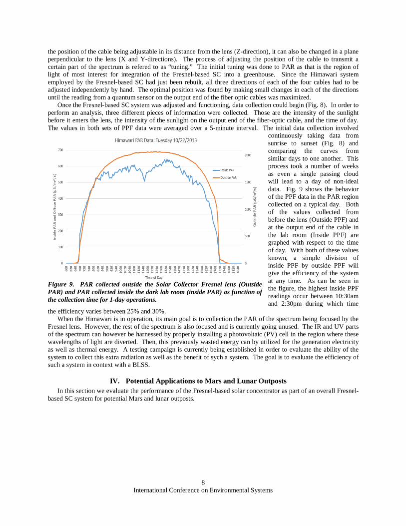
Once the Fresnel-based SC system was adjusted and functioning, data collection could begin (Fig. 8). In order to perform an analysis, three different pieces of information were collected. Those are the intensity of the sunlight before it enters the lens, the intensity of the sunlight on the output end of the fiber-optic cable, and the time of day. The values in both sets of PPF data were averaged over a 5-minute interval. The initial data collection involved
continuously taking data from sunrise to sunset (Fig. 8) and comparing the curves from similar days to one another. This process took a number of weeks as even a single passing cloud will lead to a day of non-ideal data. Fig. 9 shows the behavior of the PPF data in the PAR region collected on a typical day. Both of the values collected from before the lens (Outside PPF) and at the output end of the cable in the lab room (Inside PPF) are graphed with respect to the time of day. With both of these values known, a simple division of inside PPF by outside PPF will give the efficiency of the system at any time. As can be seen in the figure, the highest inside PPF readings occur between 10:30am and 2:30pm during which time
the efficiency varies between 25% and 30%. When the Himawari is in operation, its main goal is to collection the PAR of the spectrum being focused by the
Fresnel lens. However, the rest of the spectrum is also focused and is currently going unused. The IR and UV parts of the spectrum can however be harnessed by properly installing a photovoltaic (PV) cell in the region where these wavelengths of light are diverted. Then, this previously wasted energy can by utilized for the generation electricity as well as thermal energy. A testing campaign is currently being established in order to evaluate the ability of the system to collect this extra radiation as well as the benefit of sych a system. The goal is to evaluate the efficiency of such a system in context with a BLSS.
IV. Potential Applications to Mars and Lunar Outposts In this section we evaluate the performance of the Fresnel-based solar concentrator as part of an overall Fresnel-
based SC system for potential Mars and lunar outposts.
Figure 9. PAR collected outside the Solar Collector Fresnel lens (Outside PAR) and PAR collected inside the dark lab room (inside PAR) as function of the collection time for 1-day operations.
International Conference on Environmental Systems
9
A. Fresnel-based Solar Concentrator for Lunar Greenhouse Applications
For an evaluation of the Fresnel-based SC performance in a lunar environment, we consider a lunar base architecture as proposed by Sadler et al.1. As described in the paper, the architecture comprises 4 LGH modules each exhibiting a growing longitudinal area of 11.1 m2. It assumed that the lunar outpost is located at the Shackelton crater on the Moon’s south pole (“point of eternal light”). Fig. 10 shows the spectral lunar irradiance modeled assuming the Sun to behave as a black body (Planck’s law). The later represents the radiation as collected by the Fresnel-based SC mounted on the lunar outpost in tracking mode. The PPF (𝜇𝑚𝑜𝑙 𝑚−2𝑠−1) can be computed according to the following formula:
𝑃𝑃𝐹 = �1
𝐸�550𝑛𝑚
∫ 𝑀𝜆𝑑𝜆700400
(1)
Here the Moon irradiance 𝑀𝜆 has been integrated over the wavelength across the visible part of the spectrum to capture the PAR and then converted to 𝜇𝑚𝑜𝑙 𝑚−2𝑠−1. The factor 1 𝐸⁄ = 1 𝑛𝑒⁄ , comprising the energy of photon 𝑒 = ℎ𝑐 𝜆⁄ computed at a reference wavelength of 𝜆 = 550 𝑛𝑚, has been employed as conversion. Here, ℎ is the Planck constant, 𝑐 is the speed of light, and 𝑛 is Avogadro’s number. Fig. 11 shows the PPF in 𝜇𝑚𝑜𝑙 𝑚−2𝑠−1experienced by the LGH modules as function of the Fresnel-based SC efficiency. Fig. 12 shows the Daily PPF as function of the efficiency assuming a 12 hours photoperiod. For a nominal 30% efficiency, the system is able to convey a daily PPF of 35.6 𝜇𝑚𝑜𝑙 𝑚−2𝑑𝑎𝑦−1 which is generally sufficient for most of the crops except wheat (see Table 119) However, for the case of wheat, for a 24 hours photoperiod, the system may deliver a daily PPF of 71.2 𝜇𝑚𝑜𝑙 𝑚−2𝑑𝑎𝑦−1 (i.e. double the amount for a 12 hours photoperiod). Next, the Fresnel-based SC area required to support a nominal PPF level of 600 𝜇𝑚𝑜𝑙 𝑚−2𝑠−1 throughout the 4 LGH modules comprising the lunar outpost has been computed. This is equivalent to a total power requirement of 5.78 𝑘𝑊 (1.44 𝑘𝑊 per LGH module). Fig. 13 shows the area of the Fresnel-based SC as function of the
Figure 10. Irradiance on the Lunar Surface
Figure 11. PPF on the LGH as fucntion of the Fresnel-based SC efficiency
Figure 12. Daily PPF as function of the Fresnel-based SC efficiency
International Conference on Environmental Systems
10
system efficiency. A nominal 30% efficiency requires 32. 3 𝑚2 of total solar collection area. This is equivalent to mounting 4 independent- 1.6 𝑚 radius dishes equipped with multiple units of the Fresnel-based SC (see Fig. 2). The same amount of power may be provided by conventional electrical lighting systems (e.g. HPS lamps). If a solar-power system is envisioned to provide the required lighting power, the latter executes a light-electricity and electricity-light conversion. Fig. 15 shows the required solar panel area as fucntion of the overall light-electricity-light efficiency. In this case, it is assumed a fixed and optimistic electricity-light efficiency of 35%20 whereas the solar panel efficiency is allowed to vary beween 20% and 40%. As reported in Fig. 14, the required solar collection area (assuming perfect sun-tracking) ranges between 68 𝑚2 and 138 𝑚2.
Importatly, as part of the overall SCPS, the system is able to recover the unused Infra-Red (IR) portion of the spectrum and convert it in usable electrical energy (see section II). Fig. 15 shows the amount of extractable IR-based power as fucntion of the solar concentrator area. The IR power has been computed by evaluating the total infra-red flux (𝑊/𝑚2) collected between 0.7𝜇𝑚 and 50𝜇𝑚 and assuming a sterling system efficiency of 30%. For a total collecting area of 32. 3 𝑚2 necessary to provide PAR sufficient for the four (4) LGH module, the additional extracted power is 6.7 𝑘𝑊. Importantly, those are theoretical estimates and characterization of the extractable IR power is part of the future work.
B. Fresnel-based Solar Concentrator for Potential Mars Outpost
For a Martian outpost, the use of a Fresnel-based solar concentrator is not as favorable as the lunar case. Nevertheless, our analysis demonstrates that the Fresnel-based SC may provide important energy savings. In this case, the analysis is repeated assuming that the same lunar outpost comprising four (4) LGH modules
is deployed on Mars. The amount of solar irradiance impinging on the martian surface has been reported by Crisp et al.21 and used by Ono and Cuello for initial working estimates of the available PAR on Mars22. Assuming a similar spectral irradiance profile and repeating the procedure reported in Section IV.A we computed the available PPF and
Figure 13. Area of the Fresnel-based SC as function of the system efficiency
Figure 14. Area of the Solar panels as function of the light-electricity-light efficiency
Figure 15. Potential extracted IR power as fucntion of the Fresnel-based SC area
International Conference on Environmental Systems
11
daily PPF for a solar collecting area of 32. 3 𝑚2. The results are reported in Fig. 16 and Fig. 17. For a nominal 30% system efficiency, the PPF level is established at 281 𝜇𝑚𝑜𝑙 𝑚−2𝑠−1 with a daily PPF of 12.2 𝜇𝑚𝑜𝑙 𝑚−2𝑑𝑎𝑦−1 (12 hours photoperiod). In this case, although the Daily PPF is usable, the crops lighting requirements reported in Table 1 are not met. Therefore, additional photons must be supplied by an electrical lighting system. Fig.18 reports the lighting power produced by the system and the additional power required to meet a nominal PPF of 600 𝜇𝑚𝑜𝑙 𝑚−2𝑠−1 as function of the Fresnel-based SC efficiency. A total power of 5.83 𝑘𝑊 is required to irradiate the four LGH modules. For a nominal 30% system efficiency 2.16 𝑘𝑊, (~37%) is provided by the SCPS. The additional 3.67 𝑘𝑊 (~63%) must be provided by via electric power. Importantly, for the same collecting area, the IR power for the Mars case has been computed by evaluating the total infra-red flux (𝑊/𝑚2) collected between 0.7𝜇𝑚 and 50𝜇𝑚 and assuming a sterling system efficiency of 30%. For this case, the extractable IR power is estimated to be 2.51 𝑘𝑊. Assuming a 35% electricity-light conversion efficiency, the system my provide additional 0.875 𝑘𝑊 of effective lighting power, potentially increasing the system contribution to the required lighting power to 3.05 𝑘𝑊 (~52%). As in the lunar case, those are just initial theoretical estimates.
V. Conclusions and Future Work A Fresnel-based Solar Concentrator
Power System for future Mars and lunar outposts has been proposed. Funded by the NASA Ralph Steckler Space Grant Colonization Research and Technology Development Opportunity Phase II, the system has undergone to an initial development and testing phase. Based on the commercially available Himawari technology, following the conceptual design phase, the currently available hardware has been refurbished and
deployed to evaluate the system efficiency. The testing phase comprised an extensive collection of solar data as tracked by the system in a closed-loop fashion and transmitted via fiber-optics cables to a dark room to record the transported PAR. Based on the estimated efficiency range, an analysis of the system performance as deployed on proposed lunar and martian basis comprising 4 LGH modules has been executed. The results of the preliminary analysis show the benefits of employing such a system for energy efficient BLSS deployments. Future work will
Figure 16. PPF on the LGH as fucntion of the Fresnel-based SC efficiency for the Mars outpost
Figure 17. Daily PPF on the LGH as fucntion of the Fresnel-based SC efficiency for the Mars outpost
Figure 18. Lighting power (required, generated and supplemented) as function of the Fresnel-based SC efficiency.
International Conference on Environmental Systems
12
include: 1) Non-PAR radiation Capturing and Characterization, 2) Improving performance of the PAR collection system (i.e. performance maximization), and 3) Define the upper limits of Fresnel concentrator lens size and its effect on failure of the focal point components. The main objective will be to define how much non-PAR energy (IR) can be collected and transformed in usable energy by the Fresnel-based SC system to confirm the theoretical estimate employed in this paper for Mars and lunar outpost. To this regard we will build and implement the PV system for conversion of the IR energy into electrical energy. The latter will require the design, construction and
implementation on the optical unit focal point of a liquid-cooled heat sink. We will also plan to look at improving the current system performance (i.e. efficiency) by experimenting with liquid-filled cables.
Acknowledgments The authors wish to thank NASA and the Ralph Steckler Space Grant Colonization Research and Technology
Development Opportunity Phase II investigation for their generous support that was provided to the Arizona Space Grant Consortium, Timothy Swindle, Director and Susan Brew, Program Manager. We also wish to thank Dr. Raymond Wheeler, NASA Technical Advisor; Dr. Gene Giacomelli (technical PI), Dr. Murat Kacira (Co-PI), Dr. David Story, Derek Wibben and Neil Barto, UA-CEAC.
References 1Sadler, P., R. Furfaro, G. Giacomelli and L. Patterson. 2008. Prototype BLSS Lunar Habitat. SAE International Paper No.
08ICES-0094. 2 P. Sadler, G. Giacomelli, R. Furfaro, R. Patterson, M. Kacira, “Prototype BLSS Lunar Greenhouse,” SAE Paper No. 2009-
01-2484, 39th International Conference on Environmental Systems, Savannah, Georgia, USA, 2009. 3Giacomelli, G.A., R.L. Patterson and P.D. Sadler. 2007. Telepresence Technologies and Practices for Enabling Remote
Semi-Autonomus CEA Food Production. Acta Hort. (ISHS) 761:21-31. 4Ikeda, A., Y. Tanimura, E. Ezaki, Y. Kawai, S. Nakayama, K. Iwao, and H. Kageyama. 1992. Environmental control and
operation monitoring in a plant factory using artificial light. ISFS Paper No. 304. Noordwijkerhout, The Netherlands: International Society for Horticultural Science.
5Jack, D. 1999. Evaluation of two fiber optic–based solar collection and distribution systems for bioregenerative space life support. MS thesis. Tucson, Ariz.: University of Arizona, Department of Agricultural and Biosystems Engineering.
6Jack D., A., T. Nakamura, P. Sadler, J. L. Cuello, 2002, Evaluation of two fiber optics-based solar collection and distribution systems for advanced space life support. Transactions of the ASAE, Vol. 45(5): 1547–1558.
7Cuello, J., P. Sadler, D. Jack, E. Ono, and K. Jordan. 1998. Evaluation of light transmission and distribution materials for lunar and Martian bioregenerative life support. Life Support and Biosphere Science 5(4): 389–402.
8Cuello, J., D. Jack, P. Sadler, and T. Nakamura. 1999. Hybrid solar and artificial lighting (HYSAL): Next–generation lighting strategy for bioregenerative advanced life support. SAE Paper No. 99ES–293. Warrendale, Pa.: Society of Automotive Engineers.
9Kato, D., and T. Nakamura. 1976. Application of optical fibers to the transmission of solar radiation. J. Applied Physics 47(10): 4528–4531.
10R. L. Patterson, G. A. Giacomell, P. Sadler, “Resource and Production Model for the South Pole Food Growth Chamber”, SAE Paper No. 2008-01-2011, 39h International Conference on Environmental Systems, San Francisco, CA, USA, 2008.
11 Cariou, J., J. Dugas, and L. Martin. 1982. Transport of solar energy with optical fibers. Solar Energy. 29(5): 397–406. 12http://www.nasa.gov/offices/education/centers/johnson/home/highlight-0016.html (retrieved March 9, 2014). 13Nakamura, T.; Irvin, B. R. Optical Waveguide Photovoltaic PowerGenerator. AL-TR-90-046, Air Force Astronautics
Laboratory (AFSC); 1990.
Table 1. Environmental set points used for Advanced Life Support (ALS) candidate crops in KSC testing (from Wheeler et al. 19)
International Conference on Environmental Systems
13
14Nakamura, T.; Irvin, B. R. Optical Waveguide Solar Space Power System. ASME International Solar Energy Conference, Maui, Hawaii; 1992.
15Nakamura, T.; Irvin, B. R. Development of Optical Waveguide for Survivable Solar Space Power Systems. PL-TR-92-3006, Air Force Phillips Laboratory; 1993.
16Nakamura, T., J. Case, and M. Mankamyer. 1996. Optical waveguide solar lighting system for space–based plant growing. Presented at the 1996 International Solar Energy Conference. ASME Solar Engineering 1996: 347–358. New York, N.Y.: American Society of Mechanical Engineers.
17Nakamura, T., Fraas, L., M., Avery, J., E., 2002, Solar Plant Lighting with Electric Power Generation, Presented at 32nd International Conference on Environmental Systems San Antonio, TX
18 Fechtig, H.,J.B.Hartung, K.Nagel, and G.Newkum. 1974. Lunar microcrater studies, derived meteoroid fluxed, and comparison with satellite-borne experiments. Proc.Lunar Sci.Conf., 5th, 1974 3:2463-2474.
19A. Wheeler, R. M., J. C. Sager, et al. (2003). Crop Production for Advanced Life Support Systems - Observations From the Kennedy Space Center Breadboard Project. NASA/TM-2003-211184, Kennedy Space Center, Florida, National Aeronautics and Space Administration.
20Hanford, A. J. (2004). Advanced Life Support Baseline Values and Assumptions Document. CTSD-ADV-484 A, Houston, Texas, Crew And Thermal Systems Division NASA Lyndon B. Johnson Space Center.
21Crisp, D., D. A. Paige, et al. (1994). The performance of solar cells at the Martian surface. Pasadena, CA, Jet Propulsion Laboratory.
21Ono, E. and J. Cuello (2000). Photosynthetically Active Radiation on Mars. 30th International Conference on Environmental Systems, Toulouse, France, Society of Automotive Engineers.