Friction of sheared granular layers: Role of particle dimensionality, surface roughness, and material properties Matthew Knuth Department of Geosciences, Pennsylvania State University, 522 Deike Building, University Park, Pennsylvania 16802, USA Now at Department of Geology and Geophysics, University of Wisconsin-Madison, 1215 West Dayton Street, Madison, Wisconsin 53706, USA ([email protected]) Chris Marone Department of Geosciences, Pennsylvania State University, 522 Deike Building, University Park, Pennsylvania 16802, USA [1] We report on laboratory experiments designed to investigate three fundamental deformation mechanisms for frictional shear of granular fault gouge: sliding, rolling, and dilation. Mechanisms were isolated by shearing layers composed of rods in geometric configurations that resulted in one-dimensional, two-dimensional, and rolling-only particle interactions. Results of digital video are presented with measurements of friction and strain to illuminate the distribution of shear and the relationship between particle motions and friction. The double-direct-shear configuration was used with boundary conditions of constant layer normal stress (1 MPa) and controlled shear loading rate (10 mm/s) with initial layer thickness of 6 mm. Layers were sheared in a servo-hydraulic testing machine at room temperature (22°C) and relative humidity (5 to 10%). Three materials were studied: alloy 260 brass, dried semolina pasta, and hardwood dowels, with particle diameters of 1.59 mm, 1.86 mm, and 2.06 mm, respectively. Pasta layers had mean sliding friction coefficients of 0.24, 0.11, and 0.02 in 2-D, 1-D, and rolling configurations, respectively. Layers of brass rods had average friction coefficients of 0.23, 0.15, and 0.01, respectively, in 2-D, 1-D, and rolling configurations; and the wood samples exhibited friction values of 0.18, 0.19, and 0.09, respectively. Evolution of strength during shear correlated strongly with the displacement derivative of layer thickness. SEM images document the role of surface finish on frictional properties. Rapid reorientations of particles correspond to stick-slip stress drops and may be related to the collapse and reformation of granular force chains. We find a systematic relationship between the strength of granular layers and (1) the surface roughness of particles and (2) the number of particle contact dimensions. Our data provide important insights on the mechanics of granular fault gouge and constraints on the fundamental parameters used in numerical models of tectonic faulting. Components: 7756 words, 14 figures, 1 table, 2 animations. Keywords: granular mechanics; friction; fault gouge. Index Terms: 0550 Computational Geophysics: Model verification and validation. Received 6 April 2006; Revised 26 July 2006; Accepted 6 October 2006; Published 20 March 2007. Knuth, M., and C. Marone (2007), Friction of sheared granular layers: Role of particle dimensionality, surface roughness, and material properties, Geochem. Geophys. Geosyst., 8, Q03012, doi:10.1029/2006GC001327. G 3 G 3 Geochemistry Geophysics Geosystems Published by AGU and the Geochemical Society AN ELECTRONIC JOURNAL OF THE EARTH SCIENCES Geochemistry Geophysics Geosystems Article Volume 8, Number 3 20 March 2007 Q03012, doi:10.1029/2006GC001327 ISSN: 1525-2027 Click Here for Full Articl e Copyright 2007 by the American Geophysical Union 1 of 18
Transcript
Friction of sheared granular layers: Role of particledimensionality, surface roughness, and material properties
Matthew KnuthDepartment of Geosciences, Pennsylvania State University, 522 Deike Building, University Park, Pennsylvania 16802,USA
Now at Department of Geology and Geophysics, University of Wisconsin-Madison, 1215 West Dayton Street, Madison,Wisconsin 53706, USA ([email protected])
Chris MaroneDepartment of Geosciences, Pennsylvania State University, 522 Deike Building, University Park, Pennsylvania 16802,USA
[1] We report on laboratory experiments designed to investigate three fundamental deformationmechanisms for frictional shear of granular fault gouge: sliding, rolling, and dilation. Mechanisms wereisolated by shearing layers composed of rods in geometric configurations that resulted in one-dimensional,two-dimensional, and rolling-only particle interactions. Results of digital video are presented withmeasurements of friction and strain to illuminate the distribution of shear and the relationship betweenparticle motions and friction. The double-direct-shear configuration was used with boundary conditions ofconstant layer normal stress (1 MPa) and controlled shear loading rate (10 mm/s) with initial layer thicknessof 6 mm. Layers were sheared in a servo-hydraulic testing machine at room temperature (22�C) andrelative humidity (5 to 10%). Three materials were studied: alloy 260 brass, dried semolina pasta, andhardwood dowels, with particle diameters of 1.59 mm, 1.86 mm, and 2.06 mm, respectively. Pasta layershad mean sliding friction coefficients of 0.24, 0.11, and 0.02 in 2-D, 1-D, and rolling configurations,respectively. Layers of brass rods had average friction coefficients of 0.23, 0.15, and 0.01, respectively, in2-D, 1-D, and rolling configurations; and the wood samples exhibited friction values of 0.18, 0.19, and0.09, respectively. Evolution of strength during shear correlated strongly with the displacement derivativeof layer thickness. SEM images document the role of surface finish on frictional properties. Rapidreorientations of particles correspond to stick-slip stress drops and may be related to the collapse andreformation of granular force chains. We find a systematic relationship between the strength of granularlayers and (1) the surface roughness of particles and (2) the number of particle contact dimensions. Ourdata provide important insights on the mechanics of granular fault gouge and constraints on thefundamental parameters used in numerical models of tectonic faulting.
[2] Fault zones in the upper crust and lithosphereundergo shear via brittle frictional sliding and cata-clasis, which generates a wear zone of crushed rockcalled ‘‘fault gouge’’ [e.g., Sammis et al., 1987;Scott et al., 1994; Chester et al., 2005; Reches andDewers, 2005]. Fault gouge, which can vary inwidth from tens of cm on young faults to hundredsof m on mature faults [e.g., Scholz, 1998], dictateskey aspects of fault behavior and earthquake phys-ics, including fault strength, seismic potential, andearthquake properties. For fault zones that cutquartzo-feldspathic rocks of the upper crust, gougeis often dominated by granular material. Thus un-derstanding the physical processes of granular fric-tion is critical to a quantitative interpretation of faultmechanics [e.g., Scholz, 1998].
[3] A central problem in fault mechanics andearthquake physics is that of understanding howfault gouge influences the strength and stability offrictional sliding. The mechanical and hydrologicproperties of fault gouge are critical parameters inmodels of frictional heating and thermal pressuri-zation [e.g., Irwin and Barnes, 1975; Mase andSmith, 1987; Andrews, 2002; Rice, 2006]. Theo-retical works often predict qualitative changes inbehavior for relatively minor variations in faultzone properties, and thus detailed laboratoryexperiments designed to identify and constrainsuch properties are critical.
[4] Numerical models form a vital link betweenlaboratory experiments and field observations offaulting and tectonic processes. Distinct-Element-Modeling and Finite-Element-Modeling methodshave demonstrated the contributions of grain size[Radjai et al., 1996], grain-size distribution, strainrate, and particle collision [Ketterhagen et al.,2005], among other factors. However, limitationsin computing power have restricted many of thesemodels to two-dimensional systems. This has led toa disconnect between model results and realisticbehavior observed in fault zones and laboratoryexperiments [e.g.,Mair et al., 2002;Morgan, 1999;Mair and Marone, 1999]. In particular, manyexisting numerical models predict lower overallmacroscopic frictional strength and greater vari-ability in friction as a function of shear of the layeras a whole than corresponding laboratory experi-mental results [Mair et al., 2002]. At least part ofthese differences stem from the two-dimensionalnature of many early numerical models [e.g.,Hazzard and Mair, 2003; Abe and Mair, 2005].
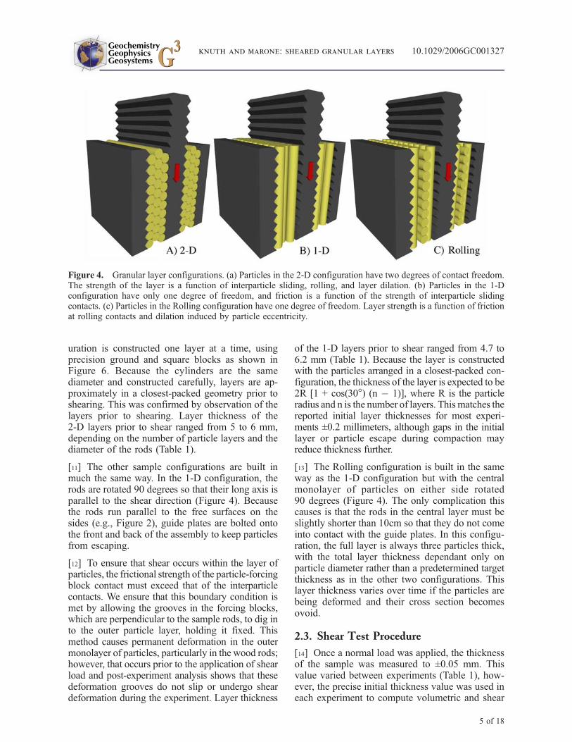
[5] The purpose of this paper is to report onexperiments designed to allow direct comparisonwith results from two-dimensional numerical sim-ulations and provide constraints on fundamentalparameters used in models of tectonic faulting. Weshear layers composed of packed cylinders ingeometric configurations that resulted in one-dimensional, two-dimensional, and rolling-onlyparticle interactions (Table 1). We use the term‘‘dimensional’’ here to indicate the degrees offreedom available to individual rods, with rods inthe 2-D configuration able to displace in both theshear and normal directions, but with rods in the 1-Dconfiguration able to displace only in the sheardirection. The 1-D configuration thus provides ameasure of intrinsic friction for interparticle slip.
2. Experimental Technique
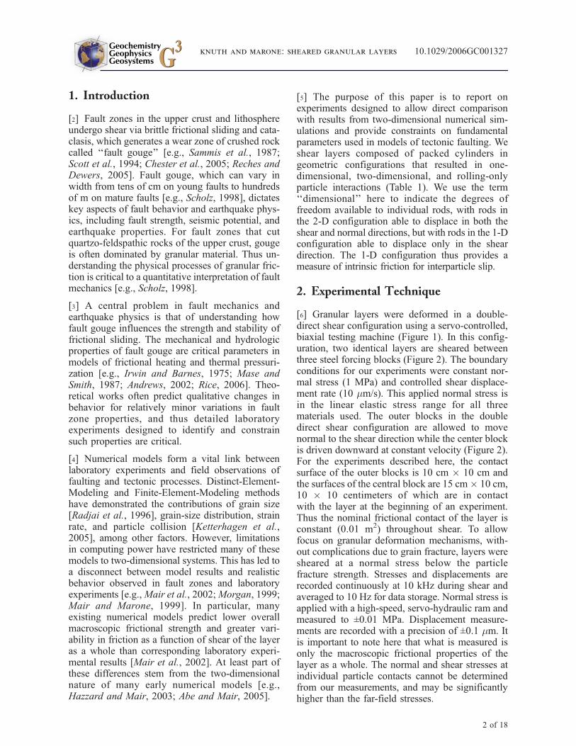
[6] Granular layers were deformed in a double-direct shear configuration using a servo-controlled,biaxial testing machine (Figure 1). In this config-uration, two identical layers are sheared betweenthree steel forcing blocks (Figure 2). The boundaryconditions for our experiments were constant nor-mal stress (1 MPa) and controlled shear displace-ment rate (10 mm/s). This applied normal stress isin the linear elastic stress range for all threematerials used. The outer blocks in the doubledirect shear configuration are allowed to movenormal to the shear direction while the center blockis driven downward at constant velocity (Figure 2).For the experiments described here, the contactsurface of the outer blocks is 10 cm � 10 cm andthe surfaces of the central block are 15 cm� 10 cm,10 � 10 centimeters of which are in contactwith the layer at the beginning of an experiment.Thus the nominal frictional contact of the layer isconstant (0.01 m2) throughout shear. To allowfocus on granular deformation mechanisms, with-out complications due to grain fracture, layers weresheared at a normal stress below the particlefracture strength. Stresses and displacements arerecorded continuously at 10 kHz during shear andaveraged to 10 Hz for data storage. Normal stress isapplied with a high-speed, servo-hydraulic ram andmeasured to ±0.01 MPa. Displacement measure-ments are recorded with a precision of ±0.1 mm. Itis important to note here that what is measured isonly the macroscopic frictional properties of thelayer as a whole. The normal and shear stresses atindividual particle contacts cannot be determinedfrom our measurements, and may be significantlyhigher than the far-field stresses.
GeochemistryGeophysicsGeosystems G3G3
knuth and marone: sheared granular layers 10.1029/2006GC001327
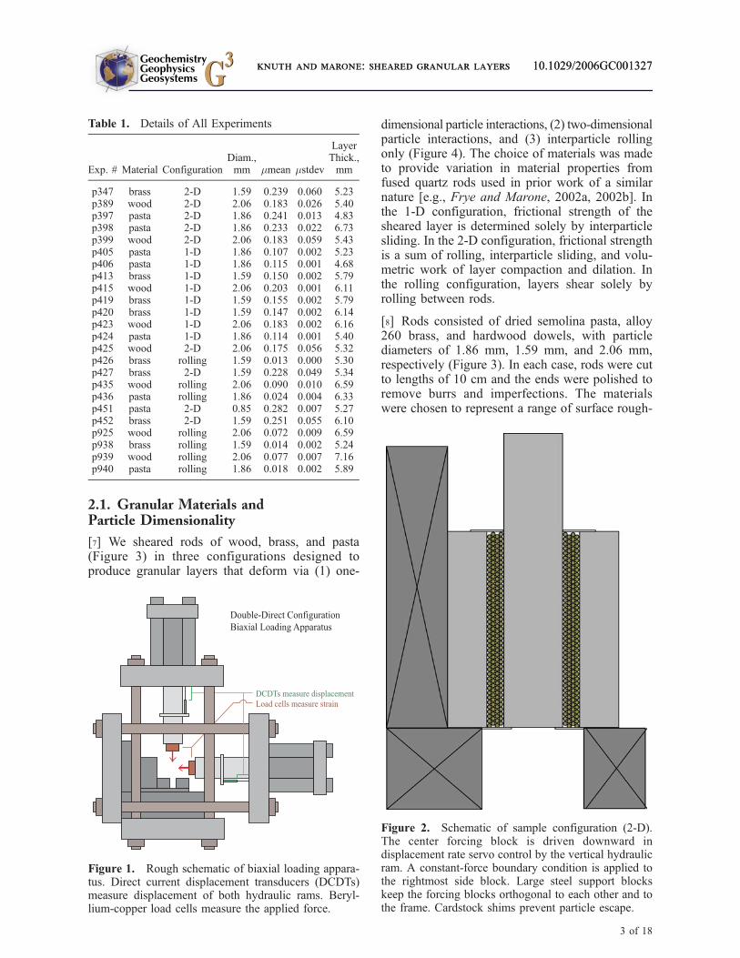
[7] We sheared rods of wood, brass, and pasta(Figure 3) in three configurations designed toproduce granular layers that deform via (1) one-
dimensional particle interactions, (2) two-dimensionalparticle interactions, and (3) interparticle rollingonly (Figure 4). The choice of materials was madeto provide variation in material properties fromfused quartz rods used in prior work of a similarnature [e.g., Frye and Marone, 2002a, 2002b]. Inthe 1-D configuration, frictional strength of thesheared layer is determined solely by interparticlesliding. In the 2-D configuration, frictional strengthis a sum of rolling, interparticle sliding, and volu-metric work of layer compaction and dilation. Inthe rolling configuration, layers shear solely byrolling between rods.
[8] Rods consisted of dried semolina pasta, alloy260 brass, and hardwood dowels, with particlediameters of 1.86 mm, 1.59 mm, and 2.06 mm,respectively (Figure 3). In each case, rods were cutto lengths of 10 cm and the ends were polished toremove burrs and imperfections. The materialswere chosen to represent a range of surface rough-
Figure 1. Rough schematic of biaxial loading appara-tus. Direct current displacement transducers (DCDTs)measure displacement of both hydraulic rams. Beryl-lium-copper load cells measure the applied force.
Figure 2. Schematic of sample configuration (2-D).The center forcing block is driven downward indisplacement rate servo control by the vertical hydraulicram. A constant-force boundary condition is applied tothe rightmost side block. Large steel support blockskeep the forcing blocks orthogonal to each other and tothe frame. Cardstock shims prevent particle escape.
Table 1. Details of All Experiments
Exp. # Material ConfigurationDiam.,mm mmean mstdev
LayerThick.,mm
p347 brass 2-D 1.59 0.239 0.060 5.23p389 wood 2-D 2.06 0.183 0.026 5.40p397 pasta 2-D 1.86 0.241 0.013 4.83p398 pasta 2-D 1.86 0.233 0.022 6.73p399 wood 2-D 2.06 0.183 0.059 5.43p405 pasta 1-D 1.86 0.107 0.002 5.23p406 pasta 1-D 1.86 0.115 0.001 4.68p413 brass 1-D 1.59 0.150 0.002 5.79p415 wood 1-D 2.06 0.203 0.001 6.11p419 brass 1-D 1.59 0.155 0.002 5.79p420 brass 1-D 1.59 0.147 0.002 6.14p423 wood 1-D 2.06 0.183 0.002 6.16p424 pasta 1-D 1.86 0.114 0.001 5.40p425 wood 2-D 2.06 0.175 0.056 5.32p426 brass rolling 1.59 0.013 0.000 5.30p427 brass 2-D 1.59 0.228 0.049 5.34p435 wood rolling 2.06 0.090 0.010 6.59p436 pasta rolling 1.86 0.024 0.004 6.33p451 pasta 2-D 0.85 0.282 0.007 5.27p452 brass 2-D 1.59 0.251 0.055 6.10p925 wood rolling 2.06 0.072 0.009 6.59p938 brass rolling 1.59 0.014 0.002 5.24p939 wood rolling 2.06 0.077 0.007 7.16p940 pasta rolling 1.86 0.018 0.002 5.89
GeochemistryGeophysicsGeosystems G3G3
knuth and marone: sheared granular layers 10.1029/2006GC001327knuth and marone: sheared granular layers 10.1029/2006GC001327
3 of 18
ness and hardness (Figure 5). Particle compress-ibility and breaking strength were measured bysubjecting a 10 cm � 10 cm monolayer of rodsto uniaxial compression between hardened steelplatens. The relationship between particle defor-mation and applied force was measured for eachmaterial over the range 0 to 60 kN; the upper limitof this range corresponds to an average, layer-normal stress of 6 MPa. Wood exhibits plasticdeformation at �30 kN, and pasta exhibits plasticdeformation at �50 kN. Brass deforms elasticallythrough 60 kN of applied force. At 10 kN appliedforce, which corresponds to the 1 MPa nominalnormal stress used in our experiments, percentaxial strain was 0.2, 0.28, and 0.44 for brass, pasta,and wood rods, respectively.
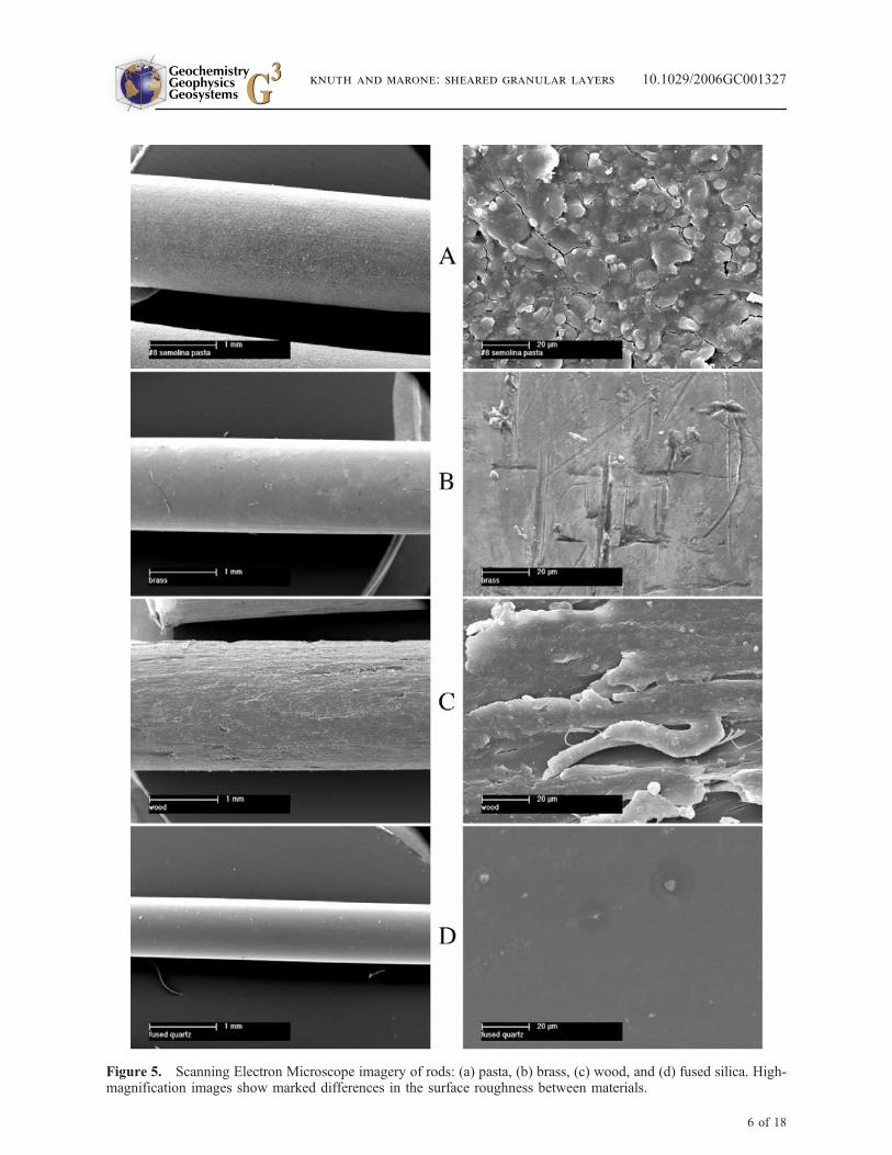
[9] SEM imagery documents significant differen-ces in the material surface roughness (Figure 5).Pasta rods are rough and exhibit a scaly texture.Brass rods are smooth but include scratches andother minor imperfections at the micron scale.Wood rods are quite rough and exhibit a fibroustexture at the scale of tens of microns (Figure 5). Alimited suite of experiments was conducted usingfused quartz rods, which are quite smooth at themicron scale (Figure 5).
2.2. Layer Construction
[10] Granular layers are constructed in a specificsequence to ensure reproducible particle packingand layer characteristics. The 2-D sample config-
Figure 3. Sample materials clockwise from left to right: #8 semolina pasta (spaghetti), hardwood dowels, and alloy260 brass rods. Inset: 1 mm fused silica rods granular shear.
GeochemistryGeophysicsGeosystems G3G3
knuth and marone: sheared granular layers 10.1029/2006GC001327
4 of 18
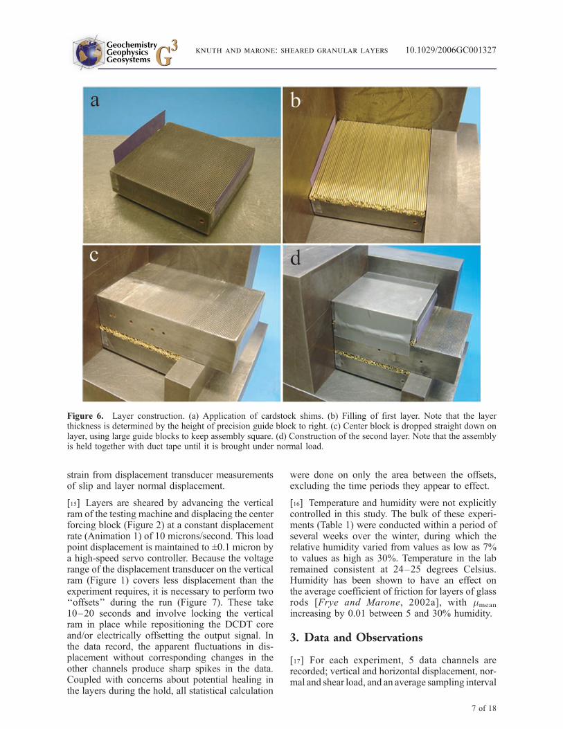
uration is constructed one layer at a time, usingprecision ground and square blocks as shown inFigure 6. Because the cylinders are the samediameter and constructed carefully, layers are ap-proximately in a closest-packed geometry prior toshearing. This was confirmed by observation of thelayers prior to shearing. Layer thickness of the2-D layers prior to shear ranged from 5 to 6 mm,depending on the number of particle layers and thediameter of the rods (Table 1).
[11] The other sample configurations are built inmuch the same way. In the 1-D configuration, therods are rotated 90 degrees so that their long axis isparallel to the shear direction (Figure 4). Becausethe rods run parallel to the free surfaces on thesides (e.g., Figure 2), guide plates are bolted ontothe front and back of the assembly to keep particlesfrom escaping.
[12] To ensure that shear occurs within the layer ofparticles, the frictional strength of the particle-forcingblock contact must exceed that of the interparticlecontacts. We ensure that this boundary condition ismet by allowing the grooves in the forcing blocks,which are perpendicular to the sample rods, to dig into the outer particle layer, holding it fixed. Thismethod causes permanent deformation in the outermonolayer of particles, particularly in the wood rods;however, that occurs prior to the application of shearload and post-experiment analysis shows that thesedeformation grooves do not slip or undergo sheardeformation during the experiment. Layer thickness
of the 1-D layers prior to shear ranged from 4.7 to6.2 mm (Table 1). Because the layer is constructedwith the particles arranged in a closest-packed con-figuration, the thickness of the layer is expected to be2R [1 + cos(30�) (n � 1)], where R is the particleradius and n is the number of layers. This matches thereported initial layer thicknesses for most experi-ments ±0.2 millimeters, although gaps in the initiallayer or particle escape during compaction mayreduce thickness further.
[13] The Rolling configuration is built in the sameway as the 1-D configuration but with the centralmonolayer of particles on either side rotated90 degrees (Figure 4). The only complication thiscauses is that the rods in the central layer must beslightly shorter than 10cm so that they do not comeinto contact with the guide plates. In this configu-ration, the full layer is always three particles thick,with the total layer thickness dependant only onparticle diameter rather than a predetermined targetthickness as in the other two configurations. Thislayer thickness varies over time if the particles arebeing deformed and their cross section becomesovoid.
2.3. Shear Test Procedure
[14] Once a normal load was applied, the thicknessof the sample was measured to ±0.05 mm. Thisvalue varied between experiments (Table 1), how-ever, the precise initial thickness value was used ineach experiment to compute volumetric and shear
Figure 4. Granular layer configurations. (a) Particles in the 2-D configuration have two degrees of contact freedom.The strength of the layer is a function of interparticle sliding, rolling, and layer dilation. (b) Particles in the 1-Dconfiguration have only one degree of freedom, and friction is a function of the strength of interparticle slidingcontacts. (c) Particles in the Rolling configuration have one degree of freedom. Layer strength is a function of frictionat rolling contacts and dilation induced by particle eccentricity.
GeochemistryGeophysicsGeosystems G3G3
knuth and marone: sheared granular layers 10.1029/2006GC001327
5 of 18
Figure 5. Scanning Electron Microscope imagery of rods: (a) pasta, (b) brass, (c) wood, and (d) fused silica. High-magnification images show marked differences in the surface roughness between materials.
GeochemistryGeophysicsGeosystems G3G3
knuth and marone: sheared granular layers 10.1029/2006GC001327
6 of 18
strain from displacement transducer measurementsof slip and layer normal displacement.
[15] Layers are sheared by advancing the verticalram of the testing machine and displacing the centerforcing block (Figure 2) at a constant displacementrate (Animation 1) of 10 microns/second. This loadpoint displacement is maintained to ±0.1 micron bya high-speed servo controller. Because the voltagerange of the displacement transducer on the verticalram (Figure 1) covers less displacement than theexperiment requires, it is necessary to perform two‘‘offsets’’ during the run (Figure 7). These take10–20 seconds and involve locking the verticalram in place while repositioning the DCDT coreand/or electrically offsetting the output signal. Inthe data record, the apparent fluctuations in dis-placement without corresponding changes in theother channels produce sharp spikes in the data.Coupled with concerns about potential healing inthe layers during the hold, all statistical calculation
were done on only the area between the offsets,excluding the time periods they appear to effect.
[16] Temperature and humidity were not explicitlycontrolled in this study. The bulk of these experi-ments (Table 1) were conducted within a period ofseveral weeks over the winter, during which therelative humidity varied from values as low as 7%to values as high as 30%. Temperature in the labremained consistent at 24–25 degrees Celsius.Humidity has been shown to have an effect onthe average coefficient of friction for layers of glassrods [Frye and Marone, 2002a], with mmean
increasing by 0.01 between 5 and 30% humidity.
3. Data and Observations
[17] For each experiment, 5 data channels arerecorded; vertical and horizontal displacement, nor-mal and shear load, and an average sampling interval
Figure 6. Layer construction. (a) Application of cardstock shims. (b) Filling of first layer. Note that the layerthickness is determined by the height of precision guide block to right. (c) Center block is dropped straight down onlayer, using large guide blocks to keep assembly square. (d) Construction of the second layer. Note that the assemblyis held together with duct tape until it is brought under normal load.
GeochemistryGeophysicsGeosystems G3G3
knuth and marone: sheared granular layers 10.1029/2006GC001327
7 of 18
(10 Hz). Shear and normal displacements are cor-rected for elastic deformation of the apparatus, usingvalues obtained in detailed calibrations. The truesample boundary displacement is used to calculateshear and volumetric strain in the layer. The voltagesignals from the load cells are converted into stressesusing the known area of the sample blocks and thecalibration values of the load cells. The coefficientof friction m for the layer is calculated by dividingthe shear stress by the normal stress (Table 1).
3.1. Two-Dimensional Configuration
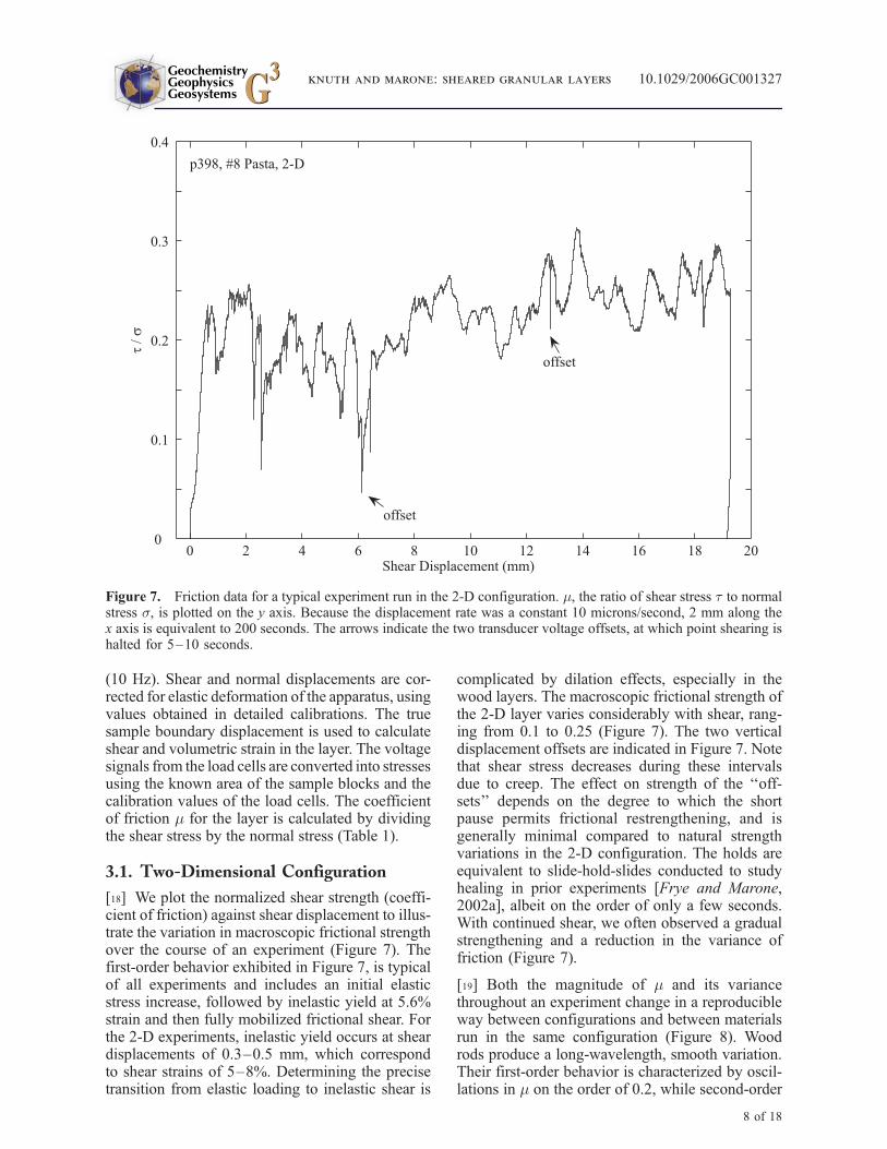
[18] We plot the normalized shear strength (coeffi-cient of friction) against shear displacement to illus-trate the variation in macroscopic frictional strengthover the course of an experiment (Figure 7). Thefirst-order behavior exhibited in Figure 7, is typicalof all experiments and includes an initial elasticstress increase, followed by inelastic yield at 5.6%strain and then fully mobilized frictional shear. Forthe 2-D experiments, inelastic yield occurs at sheardisplacements of 0.3–0.5 mm, which correspondto shear strains of 5–8%. Determining the precisetransition from elastic loading to inelastic shear is
complicated by dilation effects, especially in thewood layers. The macroscopic frictional strength ofthe 2-D layer varies considerably with shear, rang-ing from 0.1 to 0.25 (Figure 7). The two verticaldisplacement offsets are indicated in Figure 7. Notethat shear stress decreases during these intervalsdue to creep. The effect on strength of the ‘‘off-sets’’ depends on the degree to which the shortpause permits frictional restrengthening, and isgenerally minimal compared to natural strengthvariations in the 2-D configuration. The holds areequivalent to slide-hold-slides conducted to studyhealing in prior experiments [Frye and Marone,2002a], albeit on the order of only a few seconds.With continued shear, we often observed a gradualstrengthening and a reduction in the variance offriction (Figure 7).
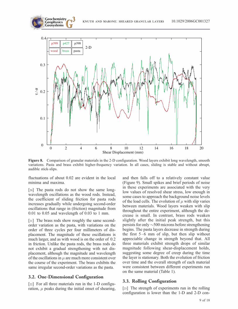
[19] Both the magnitude of m and its variancethroughout an experiment change in a reproducibleway between configurations and between materialsrun in the same configuration (Figure 8). Woodrods produce a long-wavelength, smooth variation.Their first-order behavior is characterized by oscil-lations in m on the order of 0.2, while second-order
Figure 7. Friction data for a typical experiment run in the 2-D configuration. m, the ratio of shear stress t to normalstress s, is plotted on the y axis. Because the displacement rate was a constant 10 microns/second, 2 mm along thex axis is equivalent to 200 seconds. The arrows indicate the two transducer voltage offsets, at which point shearing ishalted for 5–10 seconds.
GeochemistryGeophysicsGeosystems G3G3
knuth and marone: sheared granular layers 10.1029/2006GC001327
8 of 18
fluctuations of about 0.02 are evident in the localminima and maxima.
[20] The pasta rods do not show the same long-wavelength oscillations as the wood rods. Instead,the coefficient of sliding friction for pasta rodsincreases gradually while undergoing second-orderoscillations that range in (friction) magnitude from0.01 to 0.05 and wavelength of 0.03 to 1 mm.
[21] The brass rods show roughly the same second-order variation as the pasta, with variations on theorder of three cycles per four millimeters of dis-placement. The magnitude of these oscillations ismuch larger, and as with wood is on the order of 0.2in friction. Unlike the pasta rods, the brass rods donot exhibit a gradual strengthening with net dis-placement, although the magnitude and wavelengthof the oscillations in m are muchmore consistent overthe course of the experiment. The brass exhibits thesame irregular second-order variations as the pasta.
3.2. One-Dimensional Configuration
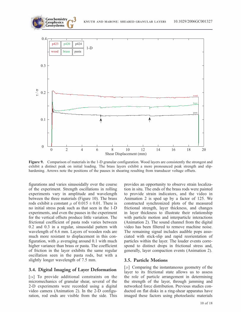
[22] For all three materials run in the 1-D configu-ration, m peaks during the initial onset of shearing,
and then falls off to a relatively constant value(Figure 9). Small spikes and brief periods of noisein these experiments are associated with the verylow values of resolved shear stress, low enough insome cases to approach the background noise levelsof the load cells. The evolution of m with slip variesbetween materials. Wood layers weaken with slipthroughout the entire experiment, although the de-crease is small. In contrast, brass rods weakenslightly after the initial peak strength, but thispersists for only�500 microns before strengtheningbegins. The pasta layers decrease in strength duringthe first 5–6 mm of slip, but then slip withoutappreciable change in strength beyond that. Allthree materials exhibit strength drops of similarmagnitude following shear-displacement holds,suggesting some degree of creep during the timethe layer is stationary. Both the evolution of frictionover time and the overall strength of each materialwere consistent between different experiments runon the same material (Table 1).
3.3. Rolling Configuration
[23] The strength of experiments run in the rollingconfiguration is lower than the 1-D and 2-D con-
Figure 8. Comparison of granular materials in the 2-D configuration. Wood layers exhibit long wavelength, smoothvariations. Pasta and brass exhibit higher-frequency variation. In all cases, sliding is stable and without abrupt,audible stick-slips.
GeochemistryGeophysicsGeosystems G3G3
knuth and marone: sheared granular layers 10.1029/2006GC001327
9 of 18
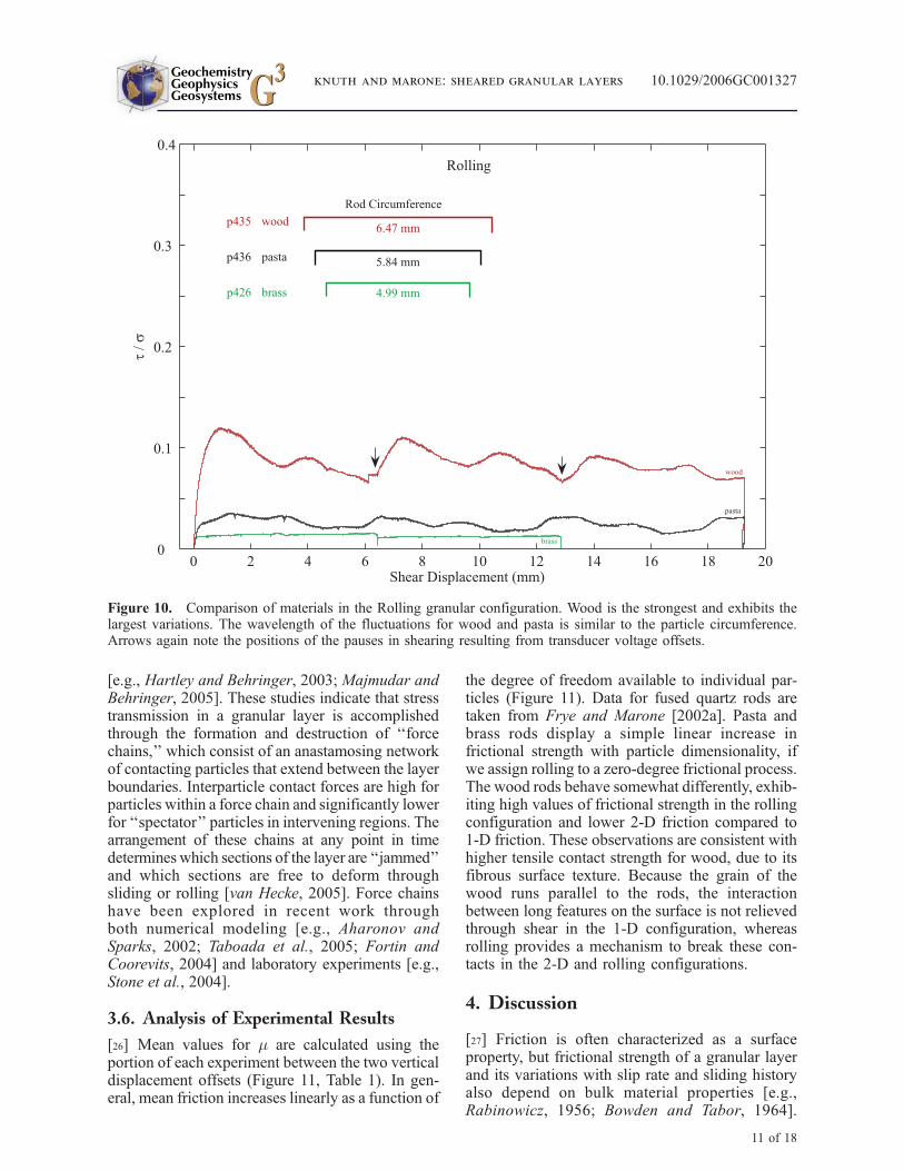
figurations and varies sinusoidally over the courseof the experiment. Strength oscillations in rollingexperiments vary in amplitude and wavelengthbetween the three materials (Figure 10). The brassrods exhibit a constant m of 0.015 ± 0.01. There isno initial stress peak such as that seen in the 1-Dexperiments, and even the pauses in the experimentfor the vertical offsets produce little variation. Thefrictional coefficient of pasta rods varies between0.2 and 0.3 in a regular, sinusoidal pattern withwavelength of 6.6 mm. Layers of wooden rods aremuch more resistant to displacement in this con-figuration, with m averaging around 0.1 with muchhigher variance than brass or pasta. The coefficientof friction in the layer exhibits the same regularoscillation seen in the pasta rods, but with aslightly longer wavelength of 7.5 mm.
3.4. Digital Imaging of Layer Deformation
[24] To provide additional constraints on themicromechanics of granular shear, several of the2-D experiments were recorded using a digitalvideo camera (Animation 2). In the 2-D configu-ration, rod ends are visible from the side. This
provides an opportunity to observe strain localiza-tion in situ. The ends of the brass rods were paintedto provide strain indicators, and the video inAnimation 2 is sped up by a factor of 125. Weconstructed synchronized plots of the measuredfrictional strength, layer thickness, and changesin layer thickness to illustrate their relationshipwith particle motion and interparticle interactions(Animation 2). The sound channel from the digitalvideo has been filtered to remove machine noise.The remaining signal includes audible pops asso-ciated with stick-slip and rapid reorientation ofparticles within the layer. The louder events corre-spond to distinct drops in frictional stress and,generally, layer compaction events (Animation 2).
3.5. Particle Motions
[25] Comparing the instantaneous geometry of thelayer to its frictional state allows us to assessthe role of particle arrangement in determiningthe strength of the layer, through jamming andnetworked force distribution. Previous studies con-ducted on flat disks in a ring-shear apparatus haveimaged these factors using photoelastic materials
Figure 9. Comparison of materials in the 1-D granular configuration. Wood layers are consistently the strongest andexhibit a distinct peak on initial loading. The brass layers exhibit a more pronounced peak strength and slip-hardening. Arrows note the positions of the pauses in shearing resulting from transducer voltage offsets.
GeochemistryGeophysicsGeosystems G3G3
knuth and marone: sheared granular layers 10.1029/2006GC001327
10 of 18
[e.g., Hartley and Behringer, 2003; Majmudar andBehringer, 2005]. These studies indicate that stresstransmission in a granular layer is accomplishedthrough the formation and destruction of ‘‘forcechains,’’ which consist of an anastamosing networkof contacting particles that extend between the layerboundaries. Interparticle contact forces are high forparticles within a force chain and significantly lowerfor ‘‘spectator’’ particles in intervening regions. Thearrangement of these chains at any point in timedetermines which sections of the layer are ‘‘jammed’’and which sections are free to deform throughsliding or rolling [van Hecke, 2005]. Force chainshave been explored in recent work throughboth numerical modeling [e.g., Aharonov andSparks, 2002; Taboada et al., 2005; Fortin andCoorevits, 2004] and laboratory experiments [e.g.,Stone et al., 2004].
3.6. Analysis of Experimental Results
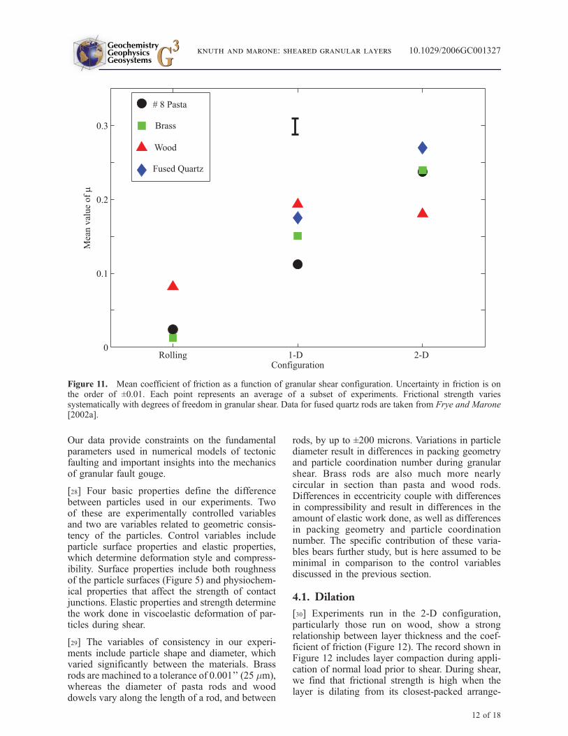
[26] Mean values for m are calculated using theportion of each experiment between the two verticaldisplacement offsets (Figure 11, Table 1). In gen-eral, mean friction increases linearly as a function of
the degree of freedom available to individual par-ticles (Figure 11). Data for fused quartz rods aretaken from Frye and Marone [2002a]. Pasta andbrass rods display a simple linear increase infrictional strength with particle dimensionality, ifwe assign rolling to a zero-degree frictional process.The wood rods behave somewhat differently, exhib-iting high values of frictional strength in the rollingconfiguration and lower 2-D friction compared to1-D friction. These observations are consistent withhigher tensile contact strength for wood, due to itsfibrous surface texture. Because the grain of thewood runs parallel to the rods, the interactionbetween long features on the surface is not relievedthrough shear in the 1-D configuration, whereasrolling provides a mechanism to break these con-tacts in the 2-D and rolling configurations.
4. Discussion
[27] Friction is often characterized as a surfaceproperty, but frictional strength of a granular layerand its variations with slip rate and sliding historyalso depend on bulk material properties [e.g.,Rabinowicz, 1956; Bowden and Tabor, 1964].
Figure 10. Comparison of materials in the Rolling granular configuration. Wood is the strongest and exhibits thelargest variations. The wavelength of the fluctuations for wood and pasta is similar to the particle circumference.Arrows again note the positions of the pauses in shearing resulting from transducer voltage offsets.
GeochemistryGeophysicsGeosystems G3G3
knuth and marone: sheared granular layers 10.1029/2006GC001327
11 of 18
Our data provide constraints on the fundamentalparameters used in numerical models of tectonicfaulting and important insights into the mechanicsof granular fault gouge.
[28] Four basic properties define the differencebetween particles used in our experiments. Twoof these are experimentally controlled variablesand two are variables related to geometric consis-tency of the particles. Control variables includeparticle surface properties and elastic properties,which determine deformation style and compress-ibility. Surface properties include both roughnessof the particle surfaces (Figure 5) and physiochem-ical properties that affect the strength of contactjunctions. Elastic properties and strength determinethe work done in viscoelastic deformation of par-ticles during shear.
[29] The variables of consistency in our experi-ments include particle shape and diameter, whichvaried significantly between the materials. Brassrods are machined to a tolerance of 0.001’’ (25 mm),whereas the diameter of pasta rods and wooddowels vary along the length of a rod, and between
rods, by up to ±200 microns. Variations in particlediameter result in differences in packing geometryand particle coordination number during granularshear. Brass rods are also much more nearlycircular in section than pasta and wood rods.Differences in eccentricity couple with differencesin compressibility and result in differences in theamount of elastic work done, as well as differencesin packing geometry and particle coordinationnumber. The specific contribution of these varia-bles bears further study, but is here assumed to beminimal in comparison to the control variablesdiscussed in the previous section.
4.1. Dilation
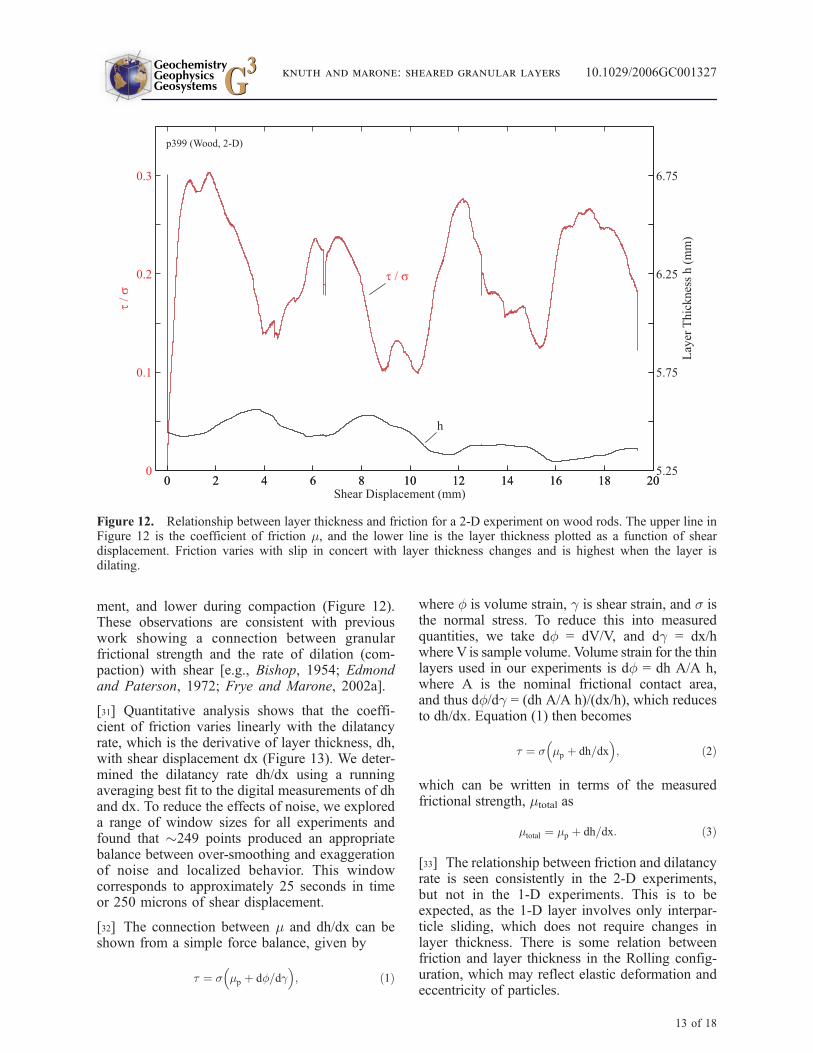
[30] Experiments run in the 2-D configuration,particularly those run on wood, show a strongrelationship between layer thickness and the coef-ficient of friction (Figure 12). The record shown inFigure 12 includes layer compaction during appli-cation of normal load prior to shear. During shear,we find that frictional strength is high when thelayer is dilating from its closest-packed arrange-
Figure 11. Mean coefficient of friction as a function of granular shear configuration. Uncertainty in friction is onthe order of ±0.01. Each point represents an average of a subset of experiments. Frictional strength variessystematically with degrees of freedom in granular shear. Data for fused quartz rods are taken from Frye and Marone[2002a].
GeochemistryGeophysicsGeosystems G3G3
knuth and marone: sheared granular layers 10.1029/2006GC001327
12 of 18
ment, and lower during compaction (Figure 12).These observations are consistent with previouswork showing a connection between granularfrictional strength and the rate of dilation (com-paction) with shear [e.g., Bishop, 1954; Edmondand Paterson, 1972; Frye and Marone, 2002a].
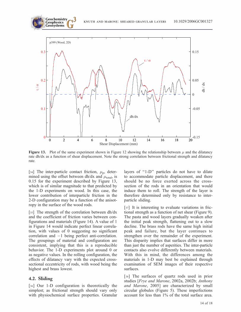
[31] Quantitative analysis shows that the coeffi-cient of friction varies linearly with the dilatancyrate, which is the derivative of layer thickness, dh,with shear displacement dx (Figure 13). We deter-mined the dilatancy rate dh/dx using a runningaveraging best fit to the digital measurements of dhand dx. To reduce the effects of noise, we exploreda range of window sizes for all experiments andfound that �249 points produced an appropriatebalance between over-smoothing and exaggerationof noise and localized behavior. This windowcorresponds to approximately 25 seconds in timeor 250 microns of shear displacement.
[32] The connection between m and dh/dx can beshown from a simple force balance, given by
t ¼ s mp þ df=dg� �
; ð1Þ
where f is volume strain, g is shear strain, and s isthe normal stress. To reduce this into measuredquantities, we take df = dV/V, and dg = dx/hwhere V is sample volume. Volume strain for the thinlayers used in our experiments is df = dh A/A h,where A is the nominal frictional contact area,and thus df/dg = (dh A/A h)/(dx/h), which reducesto dh/dx. Equation (1) then becomes
t ¼ s mp þ dh=dx� �
; ð2Þ
which can be written in terms of the measuredfrictional strength, mtotal as
mtotal ¼ mp þ dh=dx: ð3Þ
[33] The relationship between friction and dilatancyrate is seen consistently in the 2-D experiments,but not in the 1-D experiments. This is to beexpected, as the 1-D layer involves only interpar-ticle sliding, which does not require changes inlayer thickness. There is some relation betweenfriction and layer thickness in the Rolling config-uration, which may reflect elastic deformation andeccentricity of particles.
Figure 12. Relationship between layer thickness and friction for a 2-D experiment on wood rods. The upper line inFigure 12 is the coefficient of friction m, and the lower line is the layer thickness plotted as a function of sheardisplacement. Friction varies with slip in concert with layer thickness changes and is highest when the layer isdilating.
GeochemistryGeophysicsGeosystems G3G3
knuth and marone: sheared granular layers 10.1029/2006GC001327
13 of 18
[34] The inter-particle contact friction, mp, deter-mined using the offset between dh/dx and mtotal, is0.15 for the experiment described by Figure 13,which is of similar magnitude to that predicted bythe 1-D experiments on wood. In this case, thelower contribution of interparticle friction in the2-D configuration may be a function of the anisot-ropy in the surface of the wood rods.
[35] The strength of the correlation between dh/dxand the coefficient of friction varies between con-figurations and materials (Figure 14). A value of 1in Figure 14 would indicate perfect linear correla-tion, with values of 0 suggesting no significantcorrelation and �1 being perfect anti-correlation.The groupings of material and configuration areconsistent, implying that this is a reproduciblebehavior. The 1-D experiments plot around 0 oras negative values. In the rolling configuration, theeffects of dilatancy vary with the expected cross-sectional eccentricity of rods, with wood being thehighest and brass lowest.
4.2. Sliding
[36] Our 1-D configuration is theoretically thesimplest; as frictional strength should vary onlywith physiochemical surface properties. Granular
layers of ‘‘1-D’’ particles do not have to dilateto accommodate particle displacement, and thereshould be no force exerted across the cross-section of the rods in an orientation that wouldinduce them to roll. The strength of the layer istherefore determined only by resistance to inter-particle sliding.
[37] It is interesting to evaluate variations in fric-tional strength as a function of net shear (Figure 9).The pasta and wood layers gradually weaken afterthe initial peak strength, flattening out to a slowdecline. The brass rods have the same high initialpeak and failure, but the layer continues tostrengthen over the remainder of the experiment.This disparity implies that surfaces differ in morethan just the number of asperities. The inter-particlecontacts also evolve differently between materials.With this in mind, the differences among thematerials in 1-D may best be explained throughexamination of SEM images of their respectivesurfaces.
[38] The surfaces of quartz rods used in priorstudies [Frye and Marone, 2002a, 2002b; Anthonyand Marone, 2005] are characterized by smallcircular globules (Figure 5). These imperfectionsaccount for less than 1% of the total surface area.
Figure 13. Plot of the same experiment shown in Figure 12 showing the relationship between m and the dilatancyrate dh/dx as a function of shear displacement. Note the strong correlation between frictional strength and dilatancyrate.
GeochemistryGeophysicsGeosystems G3G3
knuth and marone: sheared granular layers 10.1029/2006GC001327
14 of 18
The remainder of the rod’s surface appears com-pletely smooth. Fresh rods of pasta are character-ized by an irregular network of desiccation cracksand starch nodules. The cracks are on the order ofone micron in width. The starch nodules rangefrom 10–20 square microns in area and are lessthan 20 microns in height. Images of the pasta afteran experiment did not show these cracks. Wetypically observed very fine dust after experimentswith pasta experiment, which is consistent withwear of these starch nodules.
[39] Figure 5 shows the surface of a brass rod aftershearing. It is characterized by deep gouges that are�2 microns in width (Figure 5). These do notappear on the surface of fresh rods, which arefeatureless. The wear grooves visible in Figure 5are oriented parallel to the long axis of the cylinderor on a plane orthogonal to it. The latter weregenerated by experiments run in the 2-D or rollingconfigurations, while the former were formed atsliding contacts in the 1-D configuration. Themechanism for creating these gouges could bespalling, interaction between asperities, or somecombination of the two. A large amount of adhe-sion and spalling should increase the coefficient of
friction over time [Bowden and Tabor, 1964],which is consistent with observations from the1-D experiments (Figure 9). There was no apparentresidue left behind from damage to the brass rodsduring shear.
[40] The surface of the wood rods is characterizedby deep hollows and fibrous surface projections onthe order of hundreds of square microns (Figure 5).Many of these features are roughly linear, orientedwith the grain of the wood. This orientation is tobe expected, because dowels are manufactured bycutting the wood parallel to its grain. During shearof wood rods, surface fibers become interlockedand must be detached or torn, which contributesto the high friction values observed in the 1-Dconfiguration.
4.3. Rolling
[41] The variations in friction in the rolling con-figuration reflect a different set of processes thanthose in the other configurations. With only a sin-gle layer actually being strained in this geometry,there is no need for any reordering of particlesto accommodate slip. The long, periodic changes in
Figure 14. Scatterplot of linear correlation coefficient against the coefficient of friction for all experiments.Experiments in the same configuration and with the same material plot in the same general area, suggesting goodreproducibility of results. Correlation strength in the rolling configuration is a function of particle eccentricity.
GeochemistryGeophysicsGeosystems G3G3
knuth and marone: sheared granular layers 10.1029/2006GC001327
15 of 18
strength as a function of slip (Figure 10) must bedue to some other property. Surface roughness is anunlikely candidate, as it is improbable that everycylinder would be similarly anisotropic. The cir-cumference of the wood rods is 7.4 mm, and thecircumference of the pasta rods is 6.9 mm,corresponding to their oscillation wavelengths of7.5 and 6.6 millimeters, respectively. The similaritybetween oscillation wavelength and particle cir-cumference confirms that the rods in the layer arerolling, and also implies that the pasta and woodrods are not perfectly cylindrical. The strength ofthe layer is tied to changes in its thickness, which isin turn tied to the eccentricity of the rollingparticles. Because this behavior characterizes thelayer as a whole, individual rods must either alignthemselves during initial loading, with the majoraxis of their ovoid cross-section perpendicular tothe normal stress, or else the loading itself deformsthe particles in a way that is not recoverable at therate at which the layer is sheared. In an ideal case,the thickness of a layer of rolling ellipses will varyas a sine wave between the semi-major and semi-minor axes. This is consistent with the observationthat frictional strength varies with the derivative ofthe layer thickness (Figure 14), although the cor-relation is weaker, as expected, than that observedfor the 2-D configuration.
[42] In a simple model of a rolling ovoid, wewould expect two peaks of equal height in a fullrotation; with the minima occurring just as thesemi-major axis of the particles aligns with thenormal stress direction. What we observe is thatthe first peak is significantly higher than the second(Figure 10). This may represent one of two things.Either the arrangement of the particles becomesdisturbed such they do not all share the samealignment, or else the layer is deforming as it rolls.More perfectly cylindrical particles, as evidencedby the brass rods, should exhibit minimal variationin friction when rolling. The fact that the variationin the strength of the wood rods decreases overtime may imply that the wood rods are loosingtheir eccentricity as they roll. This issue could beexplored in future work by introducing slide-hold-slide steps into the rolling experiment or by vary-ing the strain rate and normal stress throughout.
[43] Rolling friction can be attributed to severalprocesses, although some of them will only act onspheres [Bowden and Tabor, 1964]. Some strengthwill come from the work necessary to overcomeweak inter-particle attraction at the contact inter-face. Some will also come from work done in thedeformation of the contact surface, and some will
come from hysteresis associated with particle de-formation. In a true 3-D configuration composed ofspheres, contact deformation will result in ananisotropic sense of relative velocity over the totalcontact area, which may result in some degree ofsliding [Bowden and Tabor, 1964]. For rollingcylinders, some degree of interparticle slip willoccur at contact junctions prior to and during roll-ing. These processes will be exacerbated by surfaceasperities and by any time-dependant deformationthat acts to increase the area of the contact.
[44] A packed layer of rolling particles will have anadditional source of sliding friction related to thecontact between adjacent particles in front andbehind. In our experiments, the in-plane force onthese contacts is indeterminate, although ellipticalparticles would come into stronger contact whentheir semi-major axis is perpendicular to the nor-mal stress. The stress at these contacts will behighest when the layer thickness is narrowest, soany contribution to frictional strength from thesesliding contacts will add to that generated at therolling contacts.
4.4. Applicability to Fault Mechanics
[45] Determining the relative contribution of roll-ing and sliding to friction between two adjacentcylinders in the 2-D configuration is impossibleusing only macroscopic stress/strain measurementsand difficult even with the video recordings ofstrain. Computer models have proven to be ex-tremely useful in this regard, and indicate thatrolling contacts are especially important in deter-mining patterns of strain localization and distribu-tion [Morgan and Boettcher, 1999]. The surfaceproperties of synthetic materials are difficult tocompare directly with those of natural fault gougematerial. They are, however, directly applicable tonumerical approaches that address questions aboutthe formation, strength, and properties of activefault zones.
[46] Experiments such as those described hereprovide physical insight and input parametersfor numerical models of tectonic processes. Indetail, the elastic modulus of brass is higher thanthat of a typical granite, while the elastic modulusof most hardwood is comparable to that of aweak sandstone. Semolina pasta falls somewherein the middle, as does fused quartz. Conductinggranular friction tests in the lab on a range ofdifferent materials with diverse properties thusallows the results to be correlated with a widerrange of parameters in the numerical models,
GeochemistryGeophysicsGeosystems G3G3
knuth and marone: sheared granular layers 10.1029/2006GC001327
16 of 18
calibrating them to represent actual fault rockmore precisely.
[47] The nature of the interparticle surface contactsfor different materials provides another way toexplore the parameter space of the model. Thebrass surfaces describe a case where surface inter-actions are dominated by metallic adhesive pro-cesses [Bowden and Tabor, 1964], while frictionbetween wood rods is dominated by surface as-perity interactions and semolina pasta by a com-bination of asperity interactions and sub-gougeformation from their brittle outer surfaces. Theexamination of these more extreme cases providesinsight into the more heterogeneous processesacting in a natural fault zone. One could applyour results more directly by scaling the relativeeffects of adhesion, cohesion, asperities, and sub-gouge formation (e.g., spalling) in a model formacroscopic frictional strength, although that isbeyond the scope of this study.
5. Conclusions
[48] We show that material properties and surfacecharacteristics of particles have significant effectson the frictional strength of granular layers. Differ-ences between experimental configurations areexploited to isolate the role of strain accommodationmechanisms in granular layers. The frictionalstrength of 2-D granular layers varies in a reproduc-ible manner predicted by 2-D computer modeling.We observe that particle deformation style plays arole in determining the shape and periodicity ofthese variations. Experiments run in the 1-D config-uration exhibit negligible variation in strength withslip, which is consistent with pure sliding behavior.Variations in the rolling experiments scale withparticle compressibility and eccentricity. Experi-ments on pasta and brass confirm the roughly linearincrease in mean frictional strength with particle-dimensionality and degrees of particle freedomobserved by Frye and Marone [2002a]. We alsoobserve the same linear correlation between changesin layer thickness and the frictional strength of layersrun in the 2-D configuration. The strength of thiscorrelation varies between materials in a consistentand reproducible way, implying that it is affected bymaterial properties, with dilatancy in the layerimpacted by particle eccentricity and elasticity.Future work will include a detailed analysis ofvideos of experiments run in the 2-D configurationin order to elucidate changes in the layer geometryand also the use of different types of materials toexpand the range of parameters available.
Acknowledgments
[49] This work has been funded by National Science Foun-
dation grants EAR 0196570, OCE 0196462, and EAR-
0337627.
References
Abe, S., and K. Mair (2005), Grain fracture in 3D numericalsimulations of granular shear, Geophys. Res. Lett., 32,L05305, doi:10.1029/2004GL022123.
Aharonov, E., and D. Sparks (2002), Shear profiles and loca-lization in simulations of granular materials, Phys. Rev. E,65, 051302, doi:10.1103/PhysRevE.65.051302.
Andrews, D. J. (2002), A fault constitutive relation accountingfor thermal pressurization of pore fluid, J. Geophys. Res.,107(B12), 2363, doi:10.1029/2002JB001942.
Anthony, J. L., and C. Marone (2005), Influence of particlecharacteristics on granular friction, J. Geophys. Res., 110,B08409, doi:10.1029/2004JB003399.
Bisho, A. W. (1954), Correspondence, Geotech, 4, 43–45.Bowden, F. P., and D. Tabor (1964), The Friction and Lubri-cation of Solids Part II, Oxford Univ. Press, New York.
Chester, J. S., F. M. Chester, and A. K. Kronenberg (2005),Fracture surface energy of the Punchbowl fault, San Andreassystem, Nature, 437, 133–136, doi:10.1038/nature03942.
Edmond, J. M., and M. S. Paterson (1972), Volume changesduring the deformation of rocks at high pressures, Int. J.Rock Mech. Min. Sci., 9(2), 161–182.
Fortin, J., and P. Coorevits (2004), Selecting contact particlesin dynamics granular mechanics systems, J. Comp. Appl.Math., 168, doi:10.1016/j.cam.2003.05.025.
Frye, K.M., and C.Marone (2002a), The effect of particle dimen-sionality on Granular friction in laboratory shear zones, Geo-phys. Res. Lett., 29(19), 1916, doi:10.1029/2002GL015709.
Frye, K. M., and C. Marone (2002b), Effect of humidity ongranular friction at room temperature, J. Geophys. Res.,107(B11), 2309, doi:10.1029/2001JB000654.
Hartley, R. R., and R. P. Behringer (2003), Logarithmic ratedependence of force networks in sheared granular materials,Nature, 421, 928–930, doi:10.1038/nature01394.
Hazzard, J. F., and K. Mair (2003), The importance of the thirddimension in granular shear, Geophys. Res. Lett., 30(13),1708, doi:10.1029/2003GL017534.
Irwin, W. P., and I. Barnes (1975), Effects of geological struc-ture and metamorphic fluids on seismic behavior of the SanAndreas fault system in central and northern California,Geology, 3, 713–716.
Ketterhagen, W. R., J. S. Curtis, and C. R. Wassgren (2005),Stress results from two-dimensional granular shear flowsimulations using various collision models, Phys. Rev. E,71, 061307, doi:10.1103/PhysRevE.71.061307.
Mair, K., and C. Marone (1999), Friction of simulated faultgouge for a wide range of velocities and normal stresses,J. Geophys. Res., 104(B12), 28,899–28,914.
Mair, K., K. M. Frye, and C. Marone (2002), Influence of graincharacteristics on the friction of granular shear zones, J. Geo-phys. Res., 107(B10), 2219, doi:10.1029/2001JB000516.
Majmudar, T. S., and R. P. Behringer (2005), Contact force mea-surements and stress-induced anisotropy in granular materials,Nature, 435, 1079–1082, doi:10.1038/nature03805.
Mase, C. W., and L. Smith (1987), Effects of frictional heatingon the thermal, hydrologic, and mechanical response of afault, J. Geophys. Res., 92(B7), 6249–6272.
GeochemistryGeophysicsGeosystems G3G3
knuth and marone: sheared granular layers 10.1029/2006GC001327
17 of 18
Morgan, J. K. (1999), Numerical simulations of granularshear zones using the distinct element method: 2. Effectsof particle size distribution and interparticle friction onmechanical behavior, J. Geophys. Res., 104(B2), 2721–2732.
Morgan, J. K., and M. S. Boettcher (1999), Numerical simu-lations of granular shear zones using the distinct elementmethod: 1. Shear zone kinematics and the micromechanicsof localization, J. Geophys. Res., 104(B2), 2703–2720.
Rabinowicz, E. (1956), Stick and slip, Sci. Am., 194, 109–118.Radjai, F., M. Jean, J. Moreau, and S. Roux (1996), Forcedistributions in dense two-dimensional granular system-sPhys. Rev. Lett., 77(2), 274–277, doi:10.1103/PhysRev-Lett.77.274.
Reches, Z., and T. A. Dewers (2005), Gouge formation bydynamic pulverization during earthquake rupture, Earth Pla-net Sci. Lett., 235(1–2), 361–374.
Rice, J. R. (2006), Heating and weakening of faults duringearthquake slip, J. Geophys. Res., 111, B05311,doi:10.1029/2005JB004006.
Sammis, C., G. King, and R. Biegel (1987), The kinematics ofgouge formation, Pure Appl. Geophys., 125(5), 777–812,doi:10.1007/BF00878033.
Scholz, C. H. (1998), Earthquakes and friction laws, Nature,391, 37–42.
Scott, R. S., D. A. Lockner, J. D. Byerlee, and C. G. Sammis(1994), Triaxial testing of Lopez fault gouge at 150 MPamean effective stress, Pure Appl. Geophys., 142(3/4),doi:10.1007/BF00876063.
Stone, M. B., R. Barry, D. P. Bernstein, M. D. Pelc, T. K. Tsui,and P. Schiffer (2004), Local jamming via penetration of agranular medium, Phys. Rev. E, 70, doi:10.1103/Phys-RevE.70.041301.
Taboada, A., K.-J. Chang, F. Radjaı̈, and F. Bouchette (2005),Rheology, force transmission, and shear instabilities in fric-tional granular media from biaxial numerical tests using thecontact dynamics method, J. Geophys. Res., 110, B09202,doi:10.1029/2003JB002955.
van Hecke, M. (2005), Granular matter: Tale of tails, Nature,435, 1041–1042, doi:10.1038/4351041a.
GeochemistryGeophysicsGeosystems G3G3
knuth and marone: sheared granular layers 10.1029/2006GC001327