W hen Rogers Stirk Harbour & Partners suggested running steel bracing diago- nally across the facade of apartments in the upmarket Neo Bankside develop- ment, the client was unsurpris- ingly a little cautious. Yet with the vast majority of the first phase sold, the wind-bracing structure has turned out to be a selling point rather than a problem. “It provides a strong identity to the building and architecturally embraces the Rogers idea of show- ing structure on the outside,” says Nick Gray, development executive of Native Land, which is develop- ing Neo Bankside in joint venture with Grosvenor. “Typically people look for apart- ments where you can see the struc- ture expressed,” he says, adding that apartments with views of the bracing nodes are proving partic- ularly popular. The development, on Holland Street close to Tate Modern on Lon- don’s South Bank, consists of four diagrid pavilions ranging from 12- 24 storeys and containing a total of 217 units. These are arranged to allow pedestrian routes through the site towards the river, with the low- est block closest to the modestly scaled nearby almshouses towards Southwark Street. The bulk of the massing is closer to the Tate and the site of its Herzog & de Meuron- designed extension. Each pavilion has a similar plan, resembling a stretched hexagon. It was important that the build- ings had a simple presence, says RSHP senior director Graham Stirk, who led the design team. “The notion of the diagrid was something that could create a sense of unity throughout the develop- ment. We need to create something that’s quite structured and ordered to let the asymmetric Herzog & de Meuron building do its thing.” Originally, the steel was to be an expressed perimeter diagrid within the plane of the cladding. But it was decided to move the bracing to the outside of the building — as an exoskeleton — to allow it to oper- ate purely as a bracing system. In this way, it is isolated from any WWW.BDONLINE.CO.UK FRIDAY OCTOBER 14 2011 17 FRIDAY OCTOBER 14 2011 WWW.BDONLINE.CO.UK 16 STEEL FOCUS: NEO BANKSIDE In association with The British Constructional Steelwork Association and Tata Steel Unusually, the cross-bracing is in both compression and tension. The bracing consists of 400 x 200mm oval hollow sections stretching up to 13.3m between the nodes. Nodes occur at reinforced column locations at every three floors. Vertical beams on each side of the stair core transfer the load to the nodal floor of the bracing. “Because we wanted to ensure the system purely developed axial loads, we wanted a high degree of symmetry and we wanted to develop a single nodal arrangement in all locations,” says Steve Fuller, director at structural engineer Waterman. This family of node connectors can accommodate members joining in a pure horizontal plane or at different planar angles, as required according to their position on the building. The solution was a four-pinned nodal propeller around a central, circular hollow section spindle 350mm in diameter. This spindle is attached to a vertical steel section 4.5m in length. Both the spindle and the column had been preinstalled into the concrete main frame. The steel bracing sections taper and are attached to the spindle shaft with a Macalloy fork. The diagonal bracing is linked at each floor by a support tie that goes through the cladding into the concrete frame. One of the biggest challenges was co-ordinating the sequence of spindles, bracing, glazing and tie-backs. “Normally the steel frame connects to itself. But on this, the bracing connects into the nodes and the concrete. So you’re relying on every node as a separate in-cast item. They have to be spot-on or it won’t line up,” says Frances Walker, contracts manager of Watson Steel. At the two “prows” at opposite sides of each block, the apex of the node supports the single-glazed winter gardens on a system of props and hangers. The winter gardens have sliding screens and act as buffer zones between the apartment and the exterior. This steel structure is suspended from the bracing’s nodal structure towards the top of each tower at the lower of the two penthouse levels. At the base, the building is anchored on sturdy tie-downs into a precast concrete plinth. The bracing system presented engineer Waterman with considerable movement and thermal issues. Movement was resolved by a close tolerance specification for the pins, which were match-fitted to ensure a close fit. Thermal stresses are locked in to ensure that the bracing doesn’t expand and contract at the nodal positions. Colour was a factor. The steel is an iridescent, gunmetal grey — any darker would have affected the thermal characteristics. Four layers were applied, the last in-situ with a roller. Design of the bracing system was refined in close collaboration with steelwork contractors. “We had very good and interesting meetings with Watson Steel in Bolton trying to improve the design of the nodes and bracing. Watson’s were excellent and helped us to reduce costs,” says RSHP associate Simon Davis. STEEL CROSS-BRACING WELDED JUNCTIONS The close proximity of the bracing to the apartments meant that great attention was paid to the quality of the welds. Steelwork contractor Watson Steel Structures and RSHP worked closely together on this, with Watson creating a mock-up at the site and experimenting to get the effect the architect wanted. “Welded junctions in steelwork show the construc-tion of the elements, so the key for us is not to eliminate them visually but ensure their sizing is appropriate to the steel sections being joined, and that their quality and uniformity is as good as possible,” says RSHP’s Simon Davis. “This required a close understanding of the junctions, load paths of the steel elements, and Watson’s fabrication methods. Certain key, or more delicate, junctions were rearranged as an outcome of this collaborative process and had prepped (chamfered ended) connections to control the visual impact of the welds.” “To have 90% of the steel on show, up close and personal because of the windows, is quite unusual,” says Watson Steel Structures contracts manager LIFT CORES Capturing Bankside’s X factor The diagonal steel bracing on Rogers Stirk Harbour & Partners’ Neo Bankside is a core part of its identity — and because of its prominence, it had to look exactly right Text by Pamela Buxton Photographs by Edmund Sumner Red steel beams frame the inside of the lift hallways. Node detail 1 Brace end plate 2 Threaded receiver socket 3 Fork end lock cover 4 Spindle 5 Threaded torsion bars 6 Brace end lock cover 7 Fork and pin 8 Embedded steel stanchion 9 Oval hollow section brace 10 Tapered stiffener 11 Cheek plate to embedded section 12 Threaded anchor bars 4 5 6 9 10 11 12 7 8 1 2 3 1 6 5 9 7 8 3 4 2 2 1 Phase 1 2 Phase 2 3 New office building 4 Drop off 5 Sumner Street 6 Southwark Street 7 Almshouses 8 Herzog & de Meuron Tate Modern extension 9 Bankside 1 Level 1 plan 1 Units with views of the steel crossbracing are proving popular. A lift core with St Paul’s Cathedral in the background. Steel bracing supports the winter gardens at the prows of each building. These are expressed separately to the main building on the east of each pavilion. A stand-alone steel tower would have required a great deal of structure to withstand the wind forces. Instead, the architect was able to use a much lighter steel structure by anchoring it back to the main frame on every floor with projecting steel beams that take the wind load. The lift tower’s deadload is taken on four stanchions. The result is a lightweight, delicate and highly glazed pair of scenic lifts with great views of the Tate, the river and beyond. Frances Walker. “We did a lot of cosmetic work with a lot of cover plates… it had to look beautiful.” In particular, they came up with a way of concealing the welds inside the head of the spindle and were also able to reduce them on the forks from 20mm to 4mm. gravity-carrying load, with the exception of the steel winter gar- dens which it supports at the two “prows” of each building. Exter- nalising the bracing also cut costs significantly. The final structure has led to fewer shear walls within the plan, enabling the developer to respond better to market demand and future needs. “Creating open floors without shear walls was very important,” says Stirk. “We always believe that things change.” Legibility of structure was also vital, both from the outside and the inside, where the expression of the exterior is clearly visible in the diagonal bracing. Choice of colour was important in enabling people to “read” the building — the pri- mary structure is in an iridescent grey, while secondary structure such as the winter garden and the subsidiary structure of the lift is red. As the building is occupied, the diagrid’s strong visual struc- ture gives an overriding frame- work that is robust enough to take an array of curtains and blinds. Phase one is complete. Of the 91 apartments, only seven, plus the penthouses, are yet to be sold. The remaining two buildings are on site and are due to complete in spring 2012. A five-floor office will follow on Southwark Street by next autumn. Native Land hopes to realise total residential sales worth £400 million. PROJECT TEAM Client Native Land/Grosvenor Development manager Native Land Architect RSHP Structural engineer Waterman Structures Contractor Carillion Construction CDM consultant Capita Symonds Contractor’s architect John Robertson Architects Steelwork contractor Watson Steel Structures Quality of the exposed steel junctions was a priority.
Transcript
When Rogers StirkHarbour & Partnerssuggested runningsteel bracing diago-nally across the
facade of apartments in theupmarket Neo Bankside develop-ment, the client was unsurpris-ingly a little cautious. Yet with thevast majority of the first phasesold, the wind-bracing structurehas turned out to be a selling pointrather than a problem.
“It provides a strong identity tothe building and architecturallyembraces the Rogers idea of show-ing structure on the outside,” saysNick Gray, development executiveof Native Land, which is develop-ing Neo Bankside in joint venturewith Grosvenor.
“Typically people look for apart-ments where you can see the struc-ture expressed,” he says, addingthat apartments with views of thebracing nodes are proving partic-ularly popular.
The development, on HollandStreet close to Tate Modern on Lon-don’s South Bank, consists of fourdiagrid pavilions ranging from 12-24 storeys and containing a total of217 units. These are arranged toallow pedestrian routes through thesite towards the river, with the low-est block closest to the modestlyscaled nearby almshouses towardsSouthwark Street. The bulk of the
massing is closer to the Tate and thesite of its Herzog & de Meuron-designed extension. Each pavilionhas a similar plan, resembling astretched hexagon.
It was important that the build-ings had a simple presence, saysRSHP senior director GrahamStirk, who led the design team.“The notion of the diagrid wassomething that could create a senseof unity throughout the develop-ment. We need to create somethingthat’s quite structured and orderedto let the asymmetric Herzog & deMeuron building do its thing.”
Originally, the steel was to be anexpressed perimeter diagrid withinthe plane of the cladding. But it wasdecided to move the bracing to theoutside of the building — as anexoskeleton — to allow it to oper-ate purely as a bracing system. Inthis way, it is isolated from any
WWW.BDONLINE.CO.UK FRIDAY OCTOBER 14 2011 17FRIDAY OCTOBER 14 2011 WWW.BDONLINE.CO.UK16
STEEL FOCUS: NEO BANKSIDE In association withThe British Constructional Steelwork Association and Tata Steel
Unusually, the cross-bracing isin both compression andtension. The bracing consistsof 400 x 200mm oval hollowsections stretching up to 13.3mbetween the nodes. Nodesoccur at reinforced columnlocations at every three floors.Vertical beams on each side ofthe stair core transfer the loadto the nodal floor of thebracing.
“Because we wanted toensure the system purelydeveloped axial loads, wewanted a high degree ofsymmetry and we wanted todevelop a single nodalarrangement in all locations,”says Steve Fuller, director atstructural engineer Waterman.
This family of nodeconnectors can accommodatemembers joining in a purehorizontal plane or at differentplanar angles, as requiredaccording to their position onthe building. The solution wasa four-pinned nodal propelleraround a central, circularhollow section spindle 350mmin diameter. This spindle isattached to a vertical steelsection 4.5m in length.
Both the spindle and thecolumn had been preinstalledinto the concrete main frame.The steel bracing sectionstaper and are attached to thespindle shaft with a Macalloyfork. The diagonal bracing islinked at each floor by asupport tie that goes throughthe cladding into the concreteframe. One of the biggestchallenges was co-ordinatingthe sequence of spindles,bracing, glazing and tie-backs.
“Normally the steel frameconnects to itself. But on this,the bracing connects into thenodes and the concrete. Soyou’re relying on every node asa separate in-cast item. Theyhave to be spot-on or it won’t
line up,” says Frances Walker,contracts manager of WatsonSteel.
At the two “prows” atopposite sides of each block,the apex of the node supportsthe single-glazed wintergardens on a system of propsand hangers. The wintergardens have sliding screensand act as buffer zonesbetween the apartment and theexterior. This steel structureis suspended fromthebracing’snodalstructuretowards the top ofeach tower at the lower ofthe two penthouse levels. Atthe base, the building isanchored on sturdy tie-downsinto a precast concrete plinth.
The bracing systempresented engineer Watermanwith considerable movementand thermal issues. Movementwas resolved by a closetolerance specification for thepins, which were match-fittedto ensure a close fit. Thermalstresses are locked in toensure that the bracing doesn’texpand and contract at thenodal positions.
Colour was a factor. Thesteel is an iridescent, gunmetalgrey — any darker would haveaffected the thermalcharacteristics. Four layerswere applied, the last in-situwith a roller.
Design of the bracing systemwas refined in closecollaboration with steelworkcontractors.
“We had very good andinteresting meetings withWatson Steel in Bolton tryingto improve the design of thenodes and bracing. Watson’swere excellent and helped usto reduce costs,” says RSHPassociate Simon Davis.
STEEL CROSS-BRACING
WELDED JUNCTIONS
The close proximity of the bracingto the apartments meant that greatattention was paid to the quality ofthe welds. Steelwork contractorWatson Steel Structures and RSHPworked closely together on this,with Watson creating a mock-up atthe site and experimenting to getthe effect the architect wanted.
“Welded junctions in steelworkshow the construc-tion of theelements, so the key for us is not toeliminate them visually but ensuretheir sizing is appropriate to the steel sectionsbeing joined, and that their qualityand uniformity is as good aspossible,” says RSHP’s SimonDavis.
“This required a closeunderstanding of the junctions, loadpaths of the steel elements, andWatson’s fabrication methods.Certain key, or more delicate,junctions were rearranged as anoutcome of this collaborativeprocess and had prepped(chamfered ended) connections tocontrol the visual impact of thewelds.”
“To have 90% of the steel onshow, up close and personalbecause of the windows, is quiteunusual,” says Watson SteelStructures contracts manager
LIFT CORES
Capturing Bankside’s X factorThe diagonal steel bracing on Rogers Stirk Harbour & Partners’ Neo Bankside is a core part of its identity — and because of itsprominence, it had to look exactly rightText by Pamela Buxton Photographs by Edmund Sumner
Red steelbeams framethe inside of the lifthallways.
Node detail
1 Brace end plate2 Threaded
receiver socket3 Fork end lock
cover4 Spindle5 Threaded
torsion bars6 Brace end lock
cover7 Fork and pin8 Embedded
steel stanchion9 Oval hollow
section brace10 Tapered
stiffener11 Cheek plate
to embedded section
12 Threaded anchor bars
45
6
9
10
11
12
7
8
1
2
3
1
6
5
9
7
8
3 4
2
2
1 Phase 12 Phase 23 New office
building4 Drop off5 Sumner Street6 Southwark
Street7 Almshouses8 Herzog
& de Meuron Tate Modern extension
9 Bankside 1
Level 1plan
1
Units with views of the steel crossbracing are proving popular.
A lift core with St Paul’s Cathedral in the background.
Steel bracingsupports the winter gardensat the prows ofeach building.
These are expressedseparately to the mainbuilding on the east of eachpavilion. A stand-alone steeltower would have required agreat deal of structure towithstand the wind forces.
Instead, the architect wasable to use a much lightersteel structure by anchoring
it back to the main frame onevery floor with projectingsteel beams that take thewind load. The lift tower’sdeadload is taken on fourstanchions. The result is alightweight, delicate andhighly glazed pair of sceniclifts with great views of theTate, the river and beyond.
Frances Walker. “We did a lot ofcosmetic work with a lot of coverplates… it had to look beautiful.”
In particular, they came upwith a way of concealing thewelds inside the head of thespindle and were also able toreduce them on the forks from20mm to 4mm.
gravity-carrying load, with theexception of the steel winter gar-dens which it supports at the two“prows” of each building. Exter-nalising the bracing also cut costssignificantly.
The final structure has led tofewer shear walls within the plan,enabling the developer to respondbetter to market demand andfuture needs. “Creating open floorswithout shear walls was veryimportant,” says Stirk. “We alwaysbelieve that things change.”
Legibility of structure was alsovital, both from the outside and theinside, where the expression of theexterior is clearly visible in thediagonal bracing. Choice of colourwas important in enabling peopleto “read” the building — the pri-mary structure is in an iridescentgrey, while secondary structuresuch as the winter garden and thesubsidiary structure of the lift isred. As the building is occupied,the diagrid’s strong visual struc-ture gives an overriding frame-work that is robust enough to takean array of curtains and blinds.
Phase one is complete. Of the91 apartments, only seven, plusthe penthouses, are yet to be sold.The remaining two buildings areon site and are due to complete inspring 2012. A five-floor office willfollow on Southwark Street bynext autumn. Native Land hopesto realise total residential salesworth £400 million.
Quality of the exposed steeljunctions was a priority.
At the start of the lastcentury, BirminghamUniversity embarkedon the construction ofa crescent of grand
buildings designed by EdwardIngress Bell and Aston Webb —architect of the Admiralty Arch —and financed with the help of phi-lanthropist Andrew Carnegie.Unfortunately, the money ran outbefore the final building was built.Now, more than 100 years later,the missing link in the redbrickcrescent is under construction.
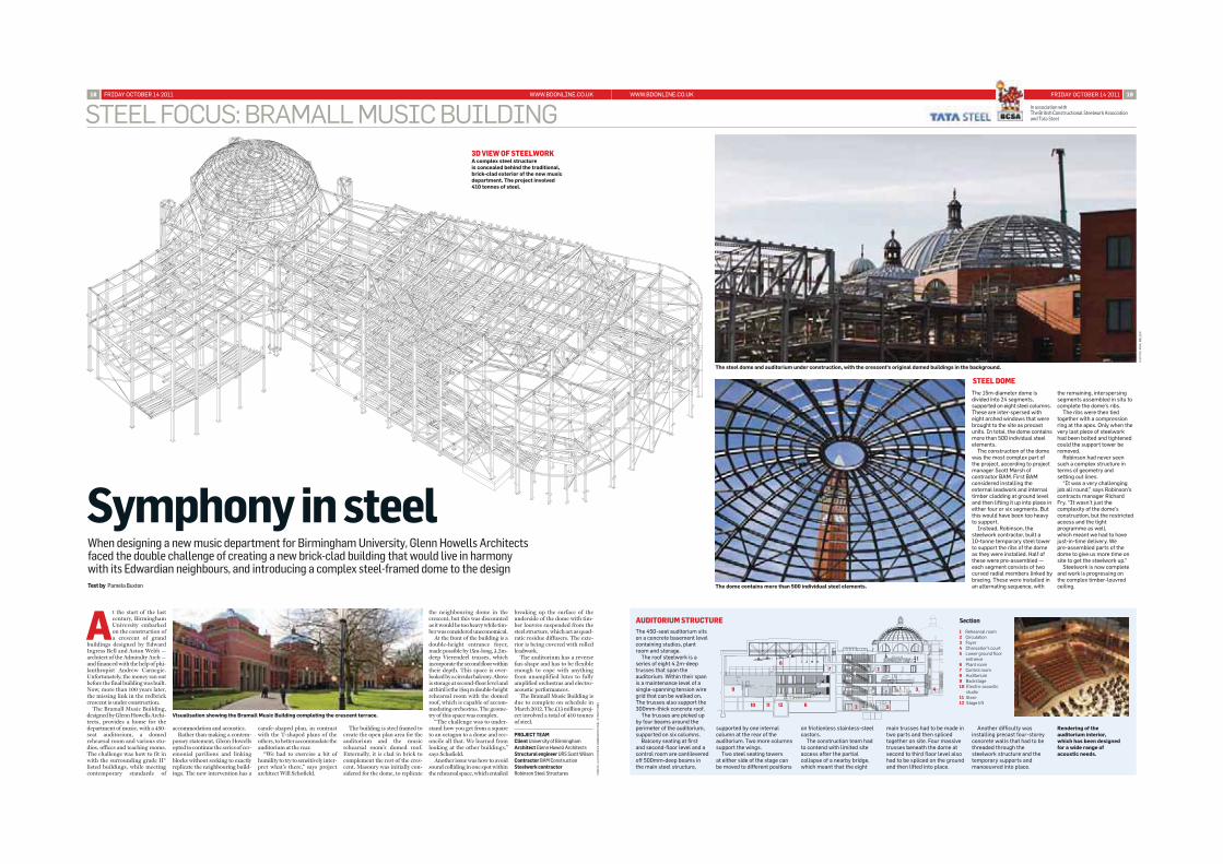
The Bramall Music Building,designed by Glenn Howells Archi-tects, provides a home for thedepartment of music, with a 450-seat auditorium, a domedrehearsal room and various stu-dios, offices and teaching rooms.The challenge was how to fit inwith the surrounding grade II*listed buildings, while meetingcontemporary standards of
accommodation and acoustics. Rather than making a contem-
porary statement, Glenn Howellsopted to continue the series of cer-emonial pavilions and linkingblocks without seeking to exactlyreplicate the neighbouring build-ings. The new intervention has a
carafe-shaped plan, in contrastwith the T-shaped plans of theothers, to better accommodate theauditorium at the rear.
“We had to exercise a bit ofhumility to try to sensitively inter-pret what’s there,” says projectarchitect Will Schofield.
The building is steel framed tocreate the open plan area for theauditorium and the musicrehearsal room’s domed roof.Externally, it is clad in brick tocomplement the rest of the cres-cent. Masonry was initially con-sidered for the dome, to replicate
the neighbouring dome in thecrescent, but this was discountedas it would be too heavy while tim-ber was considered uneconomical.
At the front of the building is adouble-height entrance foyer,made possible by 15m-long, 3.2m-deep Vierendeel trusses, whichincorporate the second floor withintheir depth. This space is over-looked by a circular balcony. Aboveis storage at second-floor level andat third is the 15sq m double-heightrehearsal room with the domedroof, which is capable of accom-modating orchestras. The geome-try of this space was complex.
“The challenge was to under-stand how you get from a squareto an octagon to a dome and rec-oncile all that. We learned fromlooking at the other buildings,”says Schofield.
Another issue was how to avoidsound colliding in one spot withinthe rehearsal space, which entailed
breaking up the surface of theunderside of the dome with tim-ber louvres suspended from thesteel structure, which act as quad-ratic residue diffusers. The exte-rior is being covered with rolledleadwork.
The auditorium has a reversefan-shape and has to be flexibleenough to cope with anythingfrom unamplified lutes to fullyamplified orchestras and electro-acoustic performances.
The Bramall Music Building isdue to complete on schedule in March 2012. The £13 million proj-ect involved a total of 410 tonnesof steel.
PROJECT TEAMClient University of BirminghamArchitect Glenn Howell ArchitectsStructural engineer URS Scott WilsonContractor BAM ConstructionSteelwork contractorRobinson Steel Structures
WWW.BDONLINE.CO.UK FRIDAY OCTOBER 14 2011 19
The 450-seat auditorium sitson a concrete basement levelcontaining studios, plantroom and storage.
The roof steelwork is aseries of eight 4.2m-deeptrusses that span theauditorium. Within their spanis a maintenance level of asingle-spanning tension wiregrid that can be walked on.The trusses also support the300mm-thick concrete roof.
The trusses are picked upby four beams around theperimeter of the auditorium,supported on six columns.
Balcony seating at first and second-floor level and acontrol room are cantileveredoff 500mm-deep beams inthe main steel structure,
In association withThe British Constructional Steelwork Association and Tata Steel
When designing a new music department for Birmingham University, Glenn Howells Architectsfaced the double challenge of creating a new brick-clad building that would live in harmony with its Edwardian neighbours, and introducing a complex steel-framed dome to the designText by Pamela Buxton
FRIDAY OCTOBER 14 2011 WWW.BDONLINE.CO.UK18
STEEL FOCUS: BRAMALL MUSIC BUILDING
The steel dome and auditorium under construction, with the crescent's original domed buildings in the background.
Visualisation showing the Bramall Music Building completing the crescent terrace.
supported by one internalcolumn at the rear of theauditorium. Two more columnssupport the wings.
Two steel seating towers at either side of the stage canbe moved to different positions
Rendering of theauditorium interior,which has been designedfor a wide range ofacoustic needs.
3D VIEW OF STEELWORKA complex steel structure is concealed behind the traditional,brick-clad exterior of the new musicdepartment. The project involved 410 tonnes of steel.
on frictionless stainless-steelcastors.
The construction team had to contend with limited siteaccess after the partialcollapse of a nearby bridge,which meant that the eight
main trusses had to be made intwo parts and then splicedtogether on site. Four massivetrusses beneath the dome atsecond to third floor level alsohad to be spliced on the groundand then lifted into place.
Another difficulty wasinstalling precast four-storeyconcrete walls that had to bethreaded through thesteelwork structure and thetemporary supports andmanoeuvred into place.
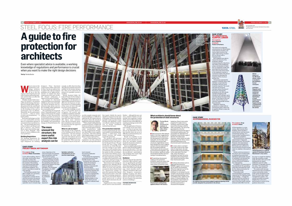
The dome contains more than 500 individual steel elements.
entrance6 Plant room7 Control room8 Auditorium9 Backstage10 Electro-acoustic
studio11 Store12 Stage lift
Section
1
2
2
3
5
4
6
78
9
10 11 12
The 15m-diameter dome isdivided into 24 segments,supported on eight steel columns.These are inter-spersed witheight arched windows that werebrought to the site as precastunits. In total, the dome containsmore than 500 individual steelelements.
The construction of the domewas the most complex part ofthe project, according to projectmanager Scott Marsh ofcontractor BAM. First BAMconsidered installing theexternal leadwork and internaltimber cladding at ground leveland then lifting it up into place ineither four or six segments. Butthis would have been too heavyto support.
Instead, Robinson, thesteelwork contractor, built a 10-tonne temporary steel towerto support the ribs of the domeas they were installed. Half ofthese were pre-assembled —each segment consists of twocurved radial members linked bybracing. These were installed inan alternating sequence, with
STEEL DOME
the remaining, interspersingsegments assembled in situ tocomplete the dome’s ribs.
The ribs were then tiedtogether with a compressionring at the apex. Only when thevery last piece of steelworkhad been bolted and tightenedcould the support tower beremoved.
Robinson had never seensuch a complex structure interms of geometry and setting out lines.
“It was a very challengingjob all round,” says Robinson’scontracts manager RichardFry. “It wasn’t just thecomplexity of the dome’sconstruction, but the restrictedaccess and the tightprogramme as well, which meant we had to havejust-in-time delivery. We pre-assembled parts of thedome to give us more time onsite to get the steelwork up.”
Steelwork is now completeand work is progressing on the complex timber-louvredceiling.
MA
IN I
LLU
ST
RA
TIO
N: R
OB
INS
ON
ST
EE
L S
TR
UC
TU
RES
PH
OT
OS
: PA
UL
MIL
LER
AUDITORIUM STRUCTURE
Symphony in steel
When it comes to fireperformance tech-nology architectsshould not leave itall up to the fire
engineer. Knowing the pros andcons of various construction mate-rials and how they can affect thedesign is essential.
Detailed, chunky timber struc-tures, for instance, can performwell by slowly forming a char layer.However, slender timber is gener-ally protected by fire-rated boardand great care needs to be takenon the detailing of this and onmaintenance over its lifetime. Meanwhile, the fire performanceof concrete — with its variety of mixes and formulations — ishard to define.
Steel’s great advantages are thatit is non-combustible and thatthere is a tremendous amount ofresearch into how it performs in afire. “The good thing about steelis that we know a lot about it andhow it behaves,” says FlorianBlock, senior structural fire engi-neer at Buro Happold. “Thismeans we can be confident in theway it performs.”
Building RegulationsThe Building Regulations forEngland and Wales set out thelegal obligations for building
designers. These functionalrequirements outline what mustbe done, but do not address howto achieve this. The governmentpublishes a set of “approved doc-uments” to explain how theserequirements can be met. For fire,the relevant publication isApproved Document B (2006).
An example of a functionalrequirement that covers structuralstability in a fire is that “the build-ing shall be designed and con-structed so that, in the event of afire, its stability will be maintainedfor a reasonable period”.
The regulations do not specifywhat a “reasonable period” is, butApproved Document B containsguidance on this. Structural fireresistance periods vary between30, 60 and 90 minutes, accordingto the occupancy and the height ofthe building, and requirementschange at 5, 18 and 30 metres. For
example, an office that is less than18m tall must maintain structuralstability for 60 minutes during afire. This can be reduced by 30minutes if a sprinkler system isinstalled.
British Standard 9999: theCode of Practice for Fire Safety inthe Design, Management and Useof Buildings, is an alternative toApproved Document B. It seeks toallow the development of solu-tions based on an understandingof the causes of risk to life andhow these can be mitigated.
It classifies buildings accord-ing to a risk profile based onoccupancy, fire growth rate, ventilation conditions and build-ing height. It also introduces anew height category for build-ings taller than 60m and gener-ally allows more attractivetrade-offs for automatic sprin-klers installation and automaticfire detection than the approveddocument does.
When to call an expertThis depends on the complexityof the building and the form ofconstruction — the more unusualthe structure, the more usefulexpert fire risk analysis can be inachieving an appropriate level offire-protection. Where prescrip-tive guidance may be overly oner-
WWW.BDONLINE.CO.UK FRIDAY OCTOBER 14 2011 21FRIDAY OCTOBER 14 2011 WWW.BDONLINE.CO.UK20
STEEL FOCUS: FIRE PERFORMANCE In association withThe British Constructional Steelwork Association and Tata Steel
A guide to fireprotection forarchitectsEven where specialist advice is available, a workingknowledge of regulations and performance is crucialwhen you want to make the right design decisionsText by Pamela Buxton
Fire engineer Arup Architect Aedas
40 Springardens is a nine-storey, steel-framed officebuilding, which includes acentral atrium and two levelsof basement parking. It isclose to other buildings and isprotected by sprinklers.
The structural fire resistancerequirement in ApprovedDocument B was 120 minutes.However, time equivalenceanalysis demonstrated that 60 minutes was sufficient toensure that the structure wouldretain its stability in the event ofa fire.
Smoke control provisions inthe atrium were installed afteran engineering assessmentdefined an appropriate amountof ventilation, and allowed theuse of toughened glazing toenclose the atrium instead offire-rated glazing.
In addition, an assessment ofthe potential for fire spreadingexternally eliminated the needfor fire-rated construction forthe external facade.
Prescriptive coderecommendations would haverequired two fire-fighting shaftsin the building. A single fire-fighting shaft was justified onthe basis that coverage to allparts of the floor plate could beachieved within 60m from the
dry riser in a single fire-fightingshaft. By providing a singleshaft, the other stair core in thebuilding did not requireadditional space for lobbyventilation or openable vents tothe stairs. This reduced thearea of the stair enclosure.
The smoke shaft size wasreduced from 3sq m to 0.6sq musing a mechanical smokeshaft system designed on thebasis of a clear layer smokemanagement system. Thissolution provided increasedlettable floor area and aperformance in excess of theguidance documents.
ous (for example composite steel-framed buildings) or difficult toapply directly, fire engineering canbe used to reduce the amount ofapplied fire protection required.
“With a simple building that hasa standard structure, it might wellbe that an architect in conjunctionwith a structural engineer and spe-cialist manufacturers mightdevelop an appropriate strategy,”says Alan Wilson, senior engineerat Arup Fire. “But when dealingwith complex designs, you’re morelikely to require expert advice.”
A basic understanding of fireregulations can help architectsdecide how much specialist advice
they require. Ideally, fire expertsshould be involved near the startof the project. Wilson says that thistypically results in greater designfreedom and ultimately a morecost-effective solution, despite thecost of having consultantsinvolved from the onset.
Fire protection materialsTo meet requirements for struc-tural stability in the Building Reg-ulations, a multi-storey, steel-framed structure will usuallyrequire fire protection.
New products and increasedcompetition mean that the cost offire protection has come down alot over the past 20 years. The pastdecade has seen a huge swingtowards the use of thin film intu-mescent coatings in new build-ings. Once a niche product, theseaccounted for more than 70% ofthe market in 2010, according tothe Construction Markets surveycarried out each year on behalf ofthe steel construction sector. Thiswas followed by board (25%) witha relatively small percentage ofspray and other niche products.
Most intumescent coatings areapplied on site, although off-siteapplication has increased in pop-ularity in recent years and nowaccounts for about a third of totaluse. Intumescent coatings arepaint-like materials that expandwhen heated to form a char withexcellent insulating properties.They can be water based, which ismostly used on site, or solventbased, which dominates the off-site market.
If applied on site, these coatingscan be used to create decorative
finishes — although this may costmore. Aesthetic finishes are alsopossible when applying a coatingoff site, however this is more prob-lematic because of the difficulty ofrepairing any damage on site to thesame standard.
Off-site application of intumes-cent coatings can be more expen-sive in terms of up-front coststhan on-site alternatives, but canhave benefits where site access isdifficult or restricted and may savecosts in the long run.
Boards are available in twotypes: heavy duty boards, whichtake decorative finishes for aes-thetic use; and lighter, cheaperboards for situations in which aes-thetics are not important.
Sprays are lightweight productsthat are easily and cheaply applied,but are not decorative. Their usehas declined in recent years, butthey are still used — particularly inlarge buildings that require highperiods of fire resistance.
GuidanceThe Association for Specialist FireProtection offers extensive guid-ance on specifying fire protectionsystems. This includes the publi-cation Ensuring Best Practice forPassive Fire Protection in Build-ings, which describes itself as“guidance intended to offer archi-tects, designers, constructors,building occupiers and others,effective and feasible recommen-dations and selection criteria forthe use of passive fire protectionsystems in buildings”.
� Steel structures often behavebetter in fire than suggested bystandard fire tests, because ofthe development of alternativeload paths. On the other hand,complex and unusual steelstructures might behave worsethan standard fire tests suggest,owing to thermal expansion ofthe surrounding materials.These factors can be assessedby structural fire engineers, andthis can deliver significant safetyand aesthetic benefits and costsavings if considered early.
� If specifying intumescentcoating as fire protection,architects need to be aware thatintumescent paint expands tomany times its thickness when
heated up. Since it only worksproperly if it is able to do so,architects need to leave a gaparound the structure, which isoften overlooked. The size of thegap depends on the fireresistance period and the type ofintumescent coating used. TheAssociation for Specialist FireProtection recommends a gap of50 times the initial paintthickness, which would normallylead to gaps of 25-75mm unlessspecified differently by theintumescent paint manufacturer.
� In cases where a compart-ment wall is built on the under-side of a steel beam, the wallshould continue past the beamsto the underside of the floorslab, unless the beam isprotected to at least the samestandard as the compartmentwall using fire protection otherthan intumescent paint.
� Guidance documents such asApproved Document B orBS9999 suggest roof structuresdo not require fire protection.While this might be true for thetop storey of multi-storeybuildings, it is not always true forcomplex roof structures coveringlarger assembly buildings suchas exhibition halls, stadiums andarenas. In these buildings, thefire protection requirements ofthe roof structure need to becarefully assessed by astructural fire engineer.
CASE STUDY40 SPRINGARDENS, MANCHESTER
CASE STUDYME LONDON HOTEL,ALDWYCH, LONDON
CASE STUDYPROJECT GREEN, NOTTINGHAM
The moreunusual thestructure, themore usefulexpert fire riskanalysis can be
Fire engineer Arup Architect Maber Associates
In this office building, which isstill under construction, Arupwas able to reduce theamount of fire protection onthe outside of the buildingfrom what would have beenrequired if it had followedprescriptive guidance. As aresult, it was able to install farmore glazing.
The building is greater than30m in height. It is served bythree staircases andincorporates a central atriumvoid that connects the groundlevel to all upper areas of thebuilding. An important designaspiration was to include large
areas of glazing on theexternal facade and maintainopen connections with theinternal atrium space.
Crucial aspects of the fireengineering design includedan assessment of the risk offire spreading externally anddetermining realistic fire sizesbased on sprinkleractivation. This facilitatedthe adoption of a 100%non-fire-ratedfacade. Analternativearrangementfor ventilationof fire-fightingshafts atbasement
level removed the need for dedicated smoke shafts.
A structural fire engineeringassessment demonstratedthat 60 minutes of fire
resistance was sufficient tosatisfy the functionalrequirements of thebuilding, compared withthe prescriptiverecommendations, whichwould have required 120minutes of resistance.
Use of a mechanicallyassisted ventilationsystem for the fire-fighting lobbies on thelevels above ground
resulted in reduced shaftsizes.
What architects should know about fire protection of steel structures
Sprinkler activationcontributed to use of a non-fire-rated facade
An engineering assessment judged toughened glazing wouldprovide adequate fire protection in the atrium.
Fire engineerBuro HappoldArchitect Foster & Partners
This hotel and residentialrefurbishment for Meliá HotelsInternational includes a 10-storey steel structure, theupper eight storeys of whichform an atrium with atriangular plan.
Buro Happold was able toreduce the amount of fireprotection withoutcompromising the robustnessand safety of the building byusing a combination of tools:first, an analytical model thatdescribed the heat transferfrom a fire at the atrium baseto the steelwork; second, anumerical model of the atriumstructure to calculate theresponse of the structureduring a fire.
This process allowed theengineer to identify which steelmembers would need fireprotection and how muchwould be required. The resultwas that all structuralmembers below the base ofthe atrium required fireprotection to an 120-minutestandard dropping to 60minutes for all members up toone level above the base of theatrium. From there to the rooflevel, only the three cornercolumns required 60 minutesfire protection.
Steelwork requiringprotection is coated with anintumescent paint, which canbe applied offsite to make sitework easier.
Above:Interior of the ME Hotelatrium, whichis located inthe building’sformercourtyard.
Left: Buro Happold usedanalytical andnumericalmodels tocalculate thedistribution of steeltemperaturesthat wouldhappen duringa localised fireat the base ofthe atrium.
Intumescent coating beingapplied offsite in the factory
40 Springardens is a redevel-opment of Amethyst House inManchester’s city centre.
PH
OT
O:D
AN
IEL
HO
PK
INS
ON
Site image of the ME Hotel atriumsteelwork showingprotected membersin white and theunprotected membersin grey above.