20
IN01433P Rev.D 1 5/28/2014 OrderRite™ Frisch’s LCD 6.x Order Confirmation System Canopy & Monolith Instruction Manual

IN01433P Rev.D 1 5/28/2014
OrderRite™
Frisch’s LCD 6.x Order Confirmation System
Canopy & Monolith Instruction Manual

IN01433P Rev.D 2 5/28/2014
Table of Contents
Table of Contents ................................................................................................................. 2
Installation Instructions ......................................................................................................... 4 General Requirements ...................................................................................................... 4 Unpacking the Hardware ................................................................................................... 4 Sign Installation Procedure ............................................................................................... 4 Store Installation Procedure .............................................................................................. 6
Completing the Install........................................................................................................ 6 OCS IP Address ................................................................................................................ 7
Troubleshooting .................................................................................................................... 8 Hardware Problems .......................................................................................................... 8
Service and Maintenance ................................................................................................... 10 Replacing the Compact Flash ......................................................................................... 10
Removing the Electronics ............................................................................................... 12 Reinstalling the Electronics ............................................................................................. 13 Cleaning the Outdoor OCS Cabinet ................................................................................ 13
System Operation ............................................................................................................... 14 OCS Sign Operation Overview ....................................................................................... 14
Appendices ......................................................................................................................... 15
Appendix A: OCS Install Details ...................................................................................... 15
Appendix B: Ethernet Connector Crimping Instructions .................................................. 17 Appendix C: Specifications ............................................................................................. 18 Appendix D: Warranty ..................................................................................................... 19

IN01433P Rev.D 3 5/28/2014
Legal notices Copyright © 2014 Everbrite, LLC. All rights reserved. Everbrite and OrderRite logos are trademarks or registered trademarks of Everbrite, LLC. Reproduction, transfer, distribution, or storage of part or all of the contents in this document in any form without the prior written permission of Everbrite is prohibited. Everbrite operates a policy of on-going development. Everbrite reserves the right to make changes and improvements to any of the products described in this document without prior notice. Under no circumstances shall Everbrite be responsible for any loss of data or data or income or any special, incidental, consequential, or indirect damages howsoever caused. THE CONTENTS OF THIS DOCUMENT ARE PROVIDED “AS IS.” EXCEPT AS REQUIRED BY APPLICABLE LAW, NO WARRANTIES OF ANY KIND, EITHER EXPRESS OR IMPLIED, INCLUDING, BUT NOT LIMITED TO, THE IMPLIED WARRANTIES OF MERCHANTABILITY AND FITNESS FOR A PARTICULAR PURPOSE, ARE MADE IN RELATION TO THE ACCURACY, RELIABILITY OR CONTENTS OF THIS DOCUMENT. EVERBRITE RESERVES THE RIGHT TO REVISE THIS DOCUMENT OR WITHDRAW IT AT ANY TIME WITHOUT PRIOR NOTICE. Trademarks Product names and/or brands mentioned herein are trademarks or registered trademarks of their respective holders. Export Controls This product contains commodities, technology or software exported from the United States in accordance with the Export Administration regulations. Diversion contrary to U.S. law is prohibited.
IN01433P Rev.D 4 5/28/2014
Installation Instructions
General Requirements
Speaker and microphone are supplied by either an audio vendor or from existing system
Installer needs to ensure the sign is properly installed, connected, and grounded per all local codes
Proper concrete sign foundation with cable conduits of proper number and size need to be present
Connected primaries must remain in the conduit and be properly sealed to conduit at the foundation
Everbrite UL file is #E6733
Unpacking the Hardware
Carefully unpack the canopy and OCS POS kit. Examine them for any shipping damage. Note: The POS kit contains important items required for the installation – keep all these items together until used.
Sign Installation Procedure
1. Remove the existing speaker stand from the foundation (if applicable).
2. Obtain the CAT-5e Ethernet cable spool (white) from the POS kit located in the OCS (see Unpacking the Hardware above).
3. Pull the cable through the 1.5" data conduit from inside the store to the concrete foundation. The Ethernet cable should be run to reach the Ethernet patch panel. Leave at least 4 feet of extra cable at the sign foundation and coil a generous portion of the cable inside the equipment rack or in the ceiling above. If extra cable length will be stored in the ceiling, ensure that it is secured to the structure to prevent future injury.
Do not pull the Ethernet cable through the primary power conduit. Operation of the system will be compromised.
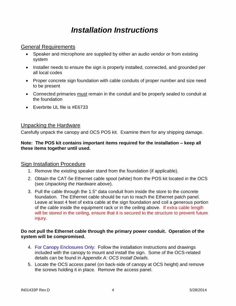
4. For Canopy Enclosures Only: Follow the installation instructions and drawings included with the canopy to mount and install the sign. Some of the OCS-related details can be found in Appendix A: OCS Install Details.
5. Locate the OCS access panel (on back-side of canopy at OCS height) and remove the screws holding it in place. Remove the access panel.

IN01433P Rev.D 5 5/28/2014
6. The OCS’s 12v power connection should be pre-wired as per the figure below.
12v POWER CONNECTION DATA CABLE (NOT USED) ETHERNET CONNECTION
7. Remove (2) RJ-45 connectors from the POS kit and crimp them onto each end of the white CAT-5e Ethernet cable (see detail below). For more information, see Appendix B: Ethernet Connector Crimping Instructions.
RJ-45 ETHERNET CRIMP CONNECTION DETAIL
8. Locate the white Ethernet cable coming from the conduit and plug it into the open jack of the surge suppressor located just above the external fans on canopy enclosures or just below the fan shelf on monolith enclosures.
IMPORTANT! THIS SIGN MUST BE WIRED TO A DEDICATED ELECTRICAL CIRCUIT BREAKER. Before making primary connections, make sure the power is off.
9. Feed the primary power wires from the power conduit into power junction box and terminate the connections (black to black, white to white, green to green).
10. Remove the speaker and microphone from the existing speaker stand (if applicable). Separate the speaker from the microphone if contained as a single unit. Make sure to label the wires in order to ensure properly reconnection later.
IN01433P Rev.D 6 5/28/2014
11. Locate the grey microphone enclosure above the LCD electronics and remove the back cover by unfastening the screws. Remove the block of foam insulation packing within the enclosure. Leave the foam wind screen and circular gasket attached to the microphone grill (if present).
12. Using a utility knife, cut a hole in the center of the block of foam large enough to insert microphone (DO NOT cut hole all the way through foam. The back of the microphone must be covered with foam). The microphone should fit snuggly within foam, and must not touch any metal when positioned in the cabinet. IMPORTANT! If microphone touches the metal of the cabinet, sound quality will be greatly reduced. Create a hole inside of the foam for the cable to exit.
13. Guide the microphone cable down through a side channel for connection. The cable cannot interfere with the operation of servicing the electronics.
14. Locate the grey speaker enclosure below the LED electronics and repeat the previous three steps to install the speaker.
15. Make the microphone and speaker connections below the shelf. The connections must be soldered. IMPORTANT! Ensure that no cables are impeding the fans from functioning or from the operation of servicing the electronics.
Store Installation Procedure
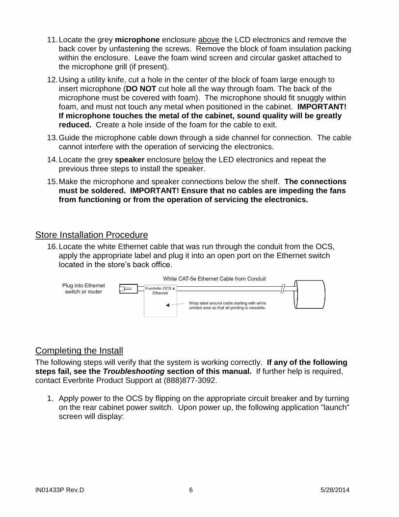
16. Locate the white Ethernet cable that was run through the conduit from the OCS, apply the appropriate label and plug it into an open port on the Ethernet switch located in the store’s back office.
Completing the Install
The following steps will verify that the system is working correctly. If any of the following steps fail, see the Troubleshooting section of this manual. If further help is required, contact Everbrite Product Support at (888)877-3092.
1. Apply power to the OCS by flipping on the appropriate circuit breaker and by turning on the rear cabinet power switch. Upon power up, the following application "launch" screen will display:

IN01433P Rev.D 7 5/28/2014
2. Make sure that the Software Configuration > POS Type is "Xpient" and that all
"Controller Feedback" tests pass (green).
3. At this point, the OCS is in perfect working condition and ready to display orders.
4. Working with store personnel, simulate a drive-thru order and verify that the order is showing up properly on the OCS display. Also verify that Frisch’s slide images are displaying on the OCS between orders.
OCS IP Address
All Frisch’s OCS systems are preprogrammed with network settings to match the latest corporate requirements. If there are problems accessing the OCS over the network, verify the network settings that appear on the boot up “launch” screen (lower right corner). The required installation procedures are now complete and the OCS back panel can now be screwed back in place.
IMPORTANT! GIVE THESE INSTRUCTIONS TO THE STORE MANAGER FOR SAFEKEEPING –
THEY WILL NEED THIS MANUAL FOR FUTURE TROUBLESHOOTING.

IN01433P Rev.D 8 5/28/2014
Troubleshooting
Hardware Problems
The following list contains common problems with their solutions. If you don't see your particular problem or the solution listed doesn't solve your problem, contact Everbrite Product Support at (888)877-3092.
Problem Possible Cause Solution
The OCS is not responding, no orders are displaying and no images are on the OCS screen (black as if switched off).
The AC power is switched off at the OCS or at the circuit breaker panel in the store.
Check the power switch located on the back of the OCS (access panel will need to be removed). The power switch will light orange when it is switched on and sees AC power. If it does not light, check the AC circuit breaker. If the breaker appears to be switched on, contact your maintenance electrician.
External power supply may be defective.
Unplug the power supply from the pigtail coming out of the electronics enclosure. Unplug the fan pigtail coming out of the electronics enclosure from the external fans. To test the supply, plug the open power supply pigtail into the external fans (the connector should fit if the correct procedure was followed). With the power switch on, the external fans should spin – if they don’t, the power supply is defective.
Note: Revert wiring back to original when complete.
The OCS may be defective. Turn the OCS off for 15 seconds and then back on (the power switch is behind OCS access panel). There are (2) indicators (amber & red) at the bottom of the OCS display. If these do not light up, check the AC power in the step above. If these do light up, but the display remains black, the OCS is defective.
The OCS is switched on with a white/yellow blank appearance.
The OCS may be defective. Turn the OCS off for 15 seconds and then back on (the power switch is behind OCS access panel). If the OCS display still has a white/yellow appearance, the OCS is defective.
The OCS is displaying images, but no orders are being displayed.
OCS not connected to store network.
Verify the following connections: 1) Within the OCS, the blue CAT-5 cable running from the silver enclosure is plugged into one end of the surge protector, 2) Within the OCS, the white CAT-5 cable running from the conduit is plugged into the other end of the surge protector and 3) Within the store, the white CAT-5 cable coming from the conduit is plugged into network switch.
OCS network settings may be incorrect.
Turn the OCS off for 15 seconds and then back on (the power switch is on the back of the OCS). Right before the slideshow displays, the launch screen will display the network settings. Make sure the settings match the latest Frisch’s corporate requirements (right).
POS settings for the OCS may be incorrect.
Contact POS technical support and verify that the software is setup for an Everbrite OCS and make sure the network configuration matches the settings in the OCS (see step above to display OCS network settings).
Upon power up, the launch screen displays a 'POS Type' other than 'Xpient'.
The setting might have been accidentally changed using the back office software.
Contact Frisch’s corporate and request a complete configuration and image package be downloaded to the store. Contact Everbrite Product Support for questions.

IN01433P Rev.D 9 5/28/2014
Problem Possible Cause Solution
Upon power up, the launch screen indicates that the external fan test has failed.
One or both of the fans may be bound up with foreign debris.
The (2) external fans are located inside the OCS just above the grey speaker enclosure. With the OCS powered off, check that any debris is cleared from the fan rotors and that they can spin freely.
The external fan wiring may have been compromised.
The (2) external fans are located inside the OCS just above the grey speaker enclosure (see above). With the OCS powered off, check the fan wiring (red & black wires) and inspect for any damage.
An external fan may be defective.
Unplug the power supply from the pigtail coming out of the electronics enclosure. Unplug the fan pigtail coming out of the electronics enclosure from the external fans. To test the fans, plug the open power supply pigtail into the external fans (the connector should fit if the correct procedure was followed). With the power switch on, the external fans should spin – if they don’t, one or more fans are defective.
Note: Revert wiring back to original when complete.
Upon power up, the launch screen indicates that the internal fan test has failed.
The internal fan may be defective.
The internal fan is not serviceable in the field. Please contact Product Support for assistance.
OCS doesn’t boot fully and gets stuck before the slideshow starts.
File corruption can prevent the system from booting.
If OCS hangs on one of screens above for more than 2 minutes:
Turn the OCS off for 30 seconds and then back on (the power switch is on the back of the OCS). Allow 2 minutes for the OCS to fully boot. If the OCS gets hung on the same screen, repeat this procedure once. If the unit still won’t boot, please contact Product Support for assistance.
IN01433P Rev.D 10 5/28/2014
Service and Maintenance
Replacing the Compact Flash
1. Remove the OCS access panel (with vents) from the rear cladding by unscrewing the fasteners and then pulling the panel out and away from the sign.
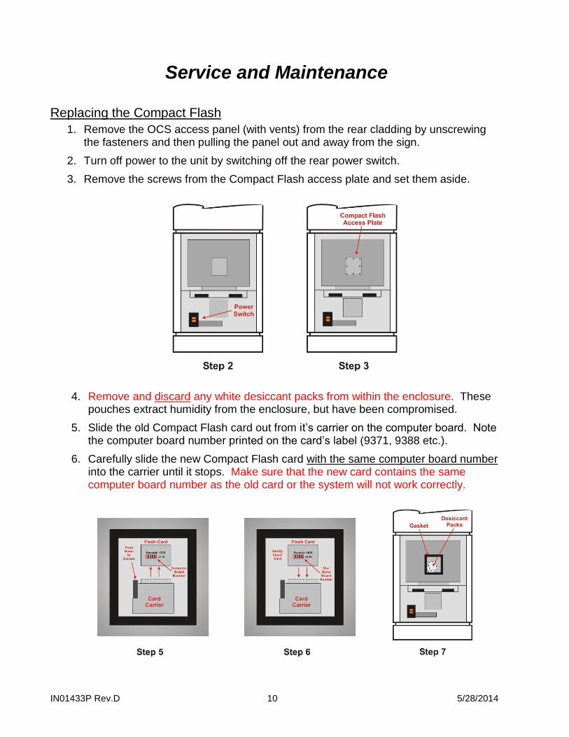
2. Turn off power to the unit by switching off the rear power switch.
3. Remove the screws from the Compact Flash access plate and set them aside.
4. Remove and discard any white desiccant packs from within the enclosure. These
pouches extract humidity from the enclosure, but have been compromised.
5. Slide the old Compact Flash card out from it’s carrier on the computer board. Note the computer board number printed on the card’s label (9371, 9388 etc.).
6. Carefully slide the new Compact Flash card with the same computer board number into the carrier until it stops. Make sure that the new card contains the same computer board number as the old card or the system will not work correctly.
IN01433P Rev.D 11 5/28/2014
7. Important! Remove new desiccant(s) from plastic, sealed pouch and place
inside the electronics enclosure.
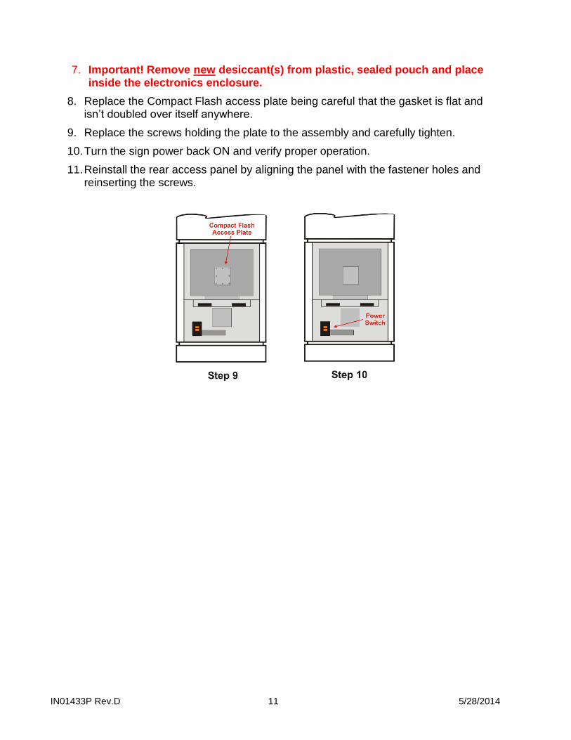
8. Replace the Compact Flash access plate being careful that the gasket is flat and isn’t doubled over itself anywhere.
9. Replace the screws holding the plate to the assembly and carefully tighten.
10. Turn the sign power back ON and verify proper operation.
11. Reinstall the rear access panel by aligning the panel with the fastener holes and reinserting the screws.

IN01433P Rev.D 12 5/28/2014
Removing the Electronics
1. Remove the OCS access panel (with vents) from the rear cladding by unscrewing the fasteners and then pulling the panel out and away from the sign.
2. Turn off power to the unit by switching off the rear, orange power switch.
3. Disconnect the power, data and fan connectors then unplug the blue network cable from the Ethernet surge suppressor located above the fans.
4. The LCD display assembly is secured to the mounting bracket from the bottom with 2 mounting screws. Remove these screws/washers and set them aside for reuse.
5. Remove the LCD display assembly by lifting it up and out of the sign cabinet.

IN01433P Rev.D 13 5/28/2014
Reinstalling the Electronics
6. Set the new LCD display assembly on top of the mounting bracket being careful not to pinch any cables coming from the back.
7. Mount the assembly by using the 2 screws/washers (from the bottom on each side).
8. Reconnect the power, data and fan connectors then insert the blue network cable into the Ethernet surge suppressor located above the fans.
9. Turn the sign power back ON and verify proper operation.
10. Reinstall the rear access panel by aligning the panel's angled slots with the mounting studs along the cladding sides and push in/down into place. Rotate the latches to lock the access panel.
Cleaning the Outdoor OCS Cabinet
Use a very mild, non-abrasive household detergent solution (ie: Dawn dish soap). Rinse with clean water and dry with a chamois or a soft cloth. Do not rub cabinet with a dry cloth or use cleaning powders, solvents, abrasives, ammonia or caustics. Avoid harsh or excessive rubbing. Note: Cleaning the OCS with a pressure washer could result in damage to the system. Any damage caused by this type of cleaning will not be covered by the warranty.

IN01433P Rev.D 14 5/28/2014
System Operation
OCS Sign Operation Overview
During the power up cycle, the OCS will perform a number of memory checks and diagnostic tests as well as display system information, configuration information and network information. The display will then begin to display a series of images. When orders are entered into the appropriate order taker POS register, the OCS will begin displaying the items ordered for the customer to confirm and verify. The OCS has internal smart controls that are constantly monitoring sunlight and temperature conditions and automatically controlling the OCS to perform optimally. The system is designed such that any changes to the configuration or images and any program updates can easily be transmitted to the OCS using Everbrite's back office software. The software can also perform remote diagnostic tests and display system, configuration and network information.

IN01433P Rev.D 15 5/28/2014
Appendices
Appendix A: OCS Install Details

IN01433P Rev.D 16 5/28/2014
Note: These drawings should be included with your sign documentation package
IN01433P Rev.D 17 5/28/2014
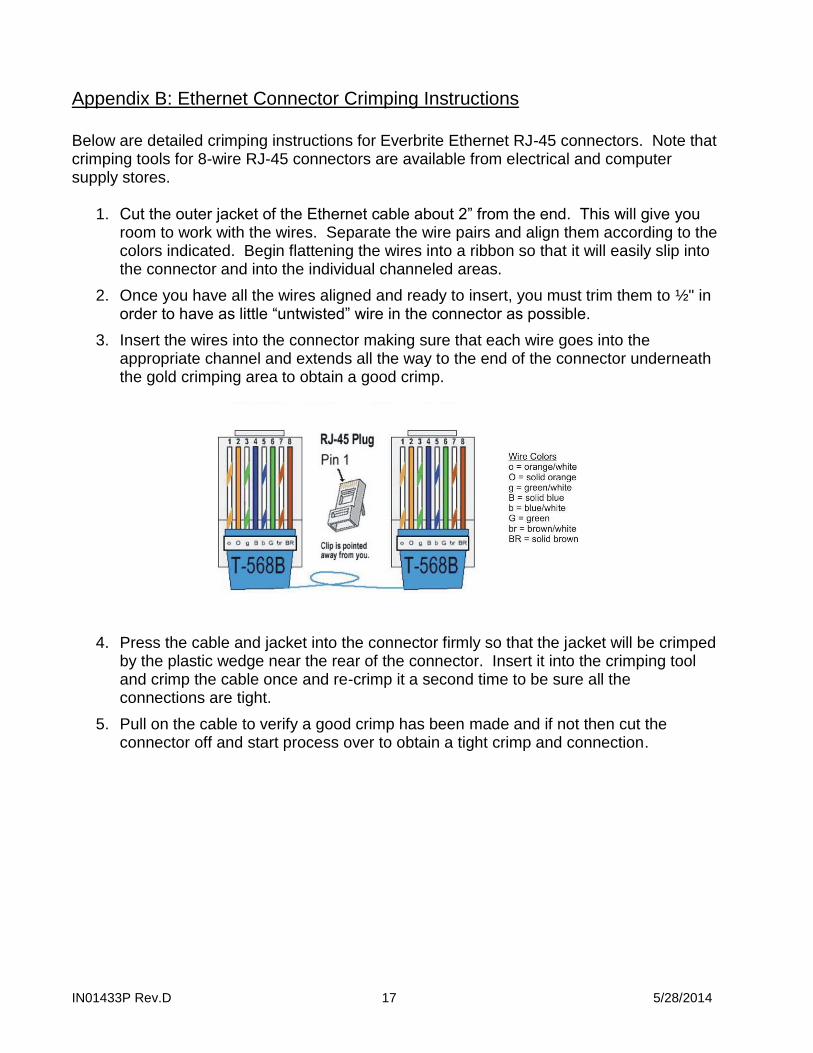
Appendix B: Ethernet Connector Crimping Instructions
Below are detailed crimping instructions for Everbrite Ethernet RJ-45 connectors. Note that crimping tools for 8-wire RJ-45 connectors are available from electrical and computer supply stores.
1. Cut the outer jacket of the Ethernet cable about 2” from the end. This will give you room to work with the wires. Separate the wire pairs and align them according to the colors indicated. Begin flattening the wires into a ribbon so that it will easily slip into the connector and into the individual channeled areas.
2. Once you have all the wires aligned and ready to insert, you must trim them to ½" in order to have as little “untwisted” wire in the connector as possible.
3. Insert the wires into the connector making sure that each wire goes into the appropriate channel and extends all the way to the end of the connector underneath the gold crimping area to obtain a good crimp.
4. Press the cable and jacket into the connector firmly so that the jacket will be crimped by the plastic wedge near the rear of the connector. Insert it into the crimping tool and crimp the cable once and re-crimp it a second time to be sure all the connections are tight.
5. Pull on the cable to verify a good crimp has been made and if not then cut the connector off and start process over to obtain a tight crimp and connection.

IN01433P Rev.D 18 5/28/2014
Appendix C: Specifications
Utilizes Everbrite’s high quality, super-bright LCD backlight rated at 50,000 hours which offers optimal visibility even in direct sunlight
Unit displays orders (line items, price, tax and total) and promotional graphics
Unit continuously monitors ambient light and adjusts display brightness
Units are designed and sealed for all outdoor weather conditions with an operating range of -40 to 122 F (-40 to 50 C)
Thermostatically controlled “silent” fans are utilized to cool the unit’s electronics
Thermostatically controlled heater for cold weather operation
The display is designed with vandal resistant laminated glass and is fully enclosed in a high quality aluminum housing
Full control of graphics can be performed in a centralized or non-centralized method
Maximum current draw of unit is 1.5A at 120VAC / 60HZ
Everbrite UL file is #E6733
Average life expectancy of 5 years if used within the conditions described in our warranty

IN01433P Rev.D 19 5/28/2014
Appendix D: Warranty Everbrite warrants the 6.x LCD Order Confirmation System (“Product”) against defects in workmanship or materials for a period of thirty six (36) months from the date of shipment. This limited warranty covers parts which are proven to be defective at the time of manufacture. During the warranty period, defective components may be replaced or repaired at Everbrite’s discretion.
Procedure to Request Warranty Service 1) Contact Everbrite’s Technical Support Department at (888) 877-3092 to report a defective condition.
Please have the unit’s serial number available and include information on the stores location, store number or code, and on-site contact information.
2) Everbrite’s Technical Support Representatives will make every effort to diagnose and trouble-shoot
reported problems over the phone.
3) Should the problem be tentatively determined to be defective component or part, a return “Call Tag” will be issued. Replacement components will be shipped to the customer, along with all packing materials and shipping labels required to return the defective components. Everbrite will be responsible for the prepaid UPS Ground shipping charges.
4) Everbrite will invoice customer for replacement components upon shipment. It is the customer’s
responsibility to return defective components to Everbrite within 10 business days in order to be eligible for full credit of replacement component invoice(s). Failure to return defective components within the specified timeframe may result in customer payment responsibility for full replacement component invoice costs and/or may void all warranties.
5) The customer is responsible for shipping the Product back to Everbrite’s factory using the above #3
referenced packaging materials. Failure to use provided packaging materials may void warranties.
6) Upon receipt, Everbrite will inspect the product and make a determination of warranty coverage. Should Everbrite determine the product is not defective, the customer may be charged associated freight costs and a nominal inspection/re-stocking fee.
Provisions/Exclusions of Warranty The three year limited warranty does not cover the following conditions:
Damage or defects caused by the failure to provide a suitable and responsible installation environment for the product
Damage caused by impact from other objects, vandalism, damage or defects resulting from acts of nature, misuse, abuse, mishandling, misapplication or faulty wiring
Damage or defects caused by disturbances or surges in the electrical service; unauthorized attachments, alterations or modifications; or improper maintenance
Everbrite will not accept any responsibility for a unit that is moved from one location and re-installed at another, unless Everbrite is contracted to handle the move.
On-site maintenance or repair services
Installation labor
Under no circumstances shall Everbrite or our installers be liable for any special, incidental, or consequential damages based upon breach of warranty, breach of contract, negligence, strict liability, or any other legal theory. Such damages include, but are not limited to, loss of profits, loss of revenue, loss of data, loss of use of the Everbrite product or any associated or connected product or equipment, cost of capital, cost of substitute or replacement equipment, facilities or services, down time, purchaser’s time, or the claims of third parties.

IN01433P Rev.D 20 5/28/2014
Disclaimer of Warranties The warranties stated above are the only warranties applicable to this product. All other warranties express or implied (including all implied warranties of merchantability or fitness for a particular purpose), are hereby disclaimed. No oral or written information, or advice given by Everbrite, its agents or employees, shall create a warranty or in any way increase the scope of this warranty. In no event shall Everbrite’s liability exceed the original price paid for the product. This limited warranty applies to the Continental United States and Canada. Rev. 4/14/2011
24 Month Extended Warranty Option: At the time of original purchase of an Everbrite 6.x LCD Order Confirmation Board, customer may elect to extend the Standard 36 Month Limited Warranty by an additional 24 Months (60 Months Total) for an additional $700.00 fee. Audio is not included with the OCS. If an existing speaker/microphone will be used in the new Everbrite OCS, and the audio cable is already run to the same foundation the new OCS unit will be mounted on, as a courtesy, the Everbrite installer will transfer the speaker/ microphone from your existing product to your new Everbrite OCS. However, Everbrite is not liable for any audio quality issues. The customer is responsible for resolving any audio issues with the appropriate audio vendor.


