This document is downloaded from DR‑NTU (https://dr.ntu.edu.sg)Nanyang Technological University, Singapore.
FRM‑based FIR filters with optimum finiteword‑length performance
Lim, Yong Ching; Yu, Ya Jun; Teo, Kok Lay; Saramäki, Tapio
2007
Lim, Y. C., Yu, Y. J., Teo, K. L., & Saramaki, T. (2007). FRM‑based FIR filters with optimumfinite word‑length performance. IEEE Transactions on Signal Processing, 55(6), 2914‑2924.
2914 IEEE TRANSACTIONS ON SIGNAL PROCESSING, VOL. 55, NO. 6, JUNE 2007
FRM-Based FIR Filters With OptimumFinite Word-Length Performance
Yong Ching Lim, Fellow, IEEE, Ya Jun Yu, Member, IEEE, Kok Lay Teo, Senior Member, IEEE, andTapio Saramäki, Fellow, IEEE
Abstract—It is well known that filters designed using the fre-quency response masking (FRM) technique have very sparse co-efficients. The number of nontrivial coefficients of a digital filterdesigned using the FRM technique is only a very small fraction ofthat of a minimax optimum design meeting the same set of specifi-cations. A digital filter designed using FRM technique is a networkof several subfilters. Several methods have been developed for op-timizing the subfilters. The earliest method optimizes the subfil-ters separately and produces a network of subfilters with excellentfinite word-length performance. Subsequent techniques optimizethe subfilters jointly and produce filters with significantly smallernumbers of nontrivial coefficients. Unfortunately, these joint opti-mization techniques, that optimize only the overall frequency re-sponse characteristics, may produce filters with undesirable finiteword-length properties. The design of FRM-based filters that si-multaneously optimizes the frequency response and finite word-length properties had not been reported in the literatures. In thispaper, we develop several new optimization approaches that in-clude the finite word-length properties of the overall filter into theoptimization process. These new approaches produce filters withexcellent finite word-length performance with almost no degrada-tion in frequency response performance.
Index Terms—Coefficient sensitivity, FIR digital filter, finiteword-length effect, frequency response masking (FRM), highselectivity filter, low complexity filter, round off noise, sharp filter,signal word-length, sparse coefficient filter.
I. INTRODUCTION
THE FREQUENCY response masking (FRM) technique[1]–[20] was developed for the synthesis of very sharp
digital filters with very sparse coefficients. Thus, a filter synthe-sized using the FRM technique has very low complexity eventhough the effective filter length is slightly longer than that ofthe minimax optimum design meeting the same set of frequencyresponse specifications. The FRM technique has been extendedto the synthesis of various types of filters such as half-band fil-ters [21]–[23], 2-D filters [24], IIR filters [25]–[28], filter banks[29]–[34], decimators and interpolators [35], [36], and Hilbert
Manuscript received June 27, 2006; revised September 28, 2006. The asso-ciate editor coordinating the review of this manuscript and approving it for pub-lication was Dr. Hakan Johansson. This work was supported in part by TemasekLaboratories, Nanyang Technological University, by Curtin University of Tech-nology, and by Tampere University of Technology.
Y. C. Lim and Y. J. Yu are with the School of Electrical and Electronic En-gineering, Nanyang Technological University, 639798, Singapore.
K. L. Teo is with the Department of Mathematics and Statistics, Curtin Uni-versity of Technology, Perth 6102, Australia.
T. Saramäki is with the Institute of Signal Processing, Tampere University ofTechnology, FIN-33101 Tampere, Finland.
Digital Object Identifier 10.1109/TSP.2007.893965
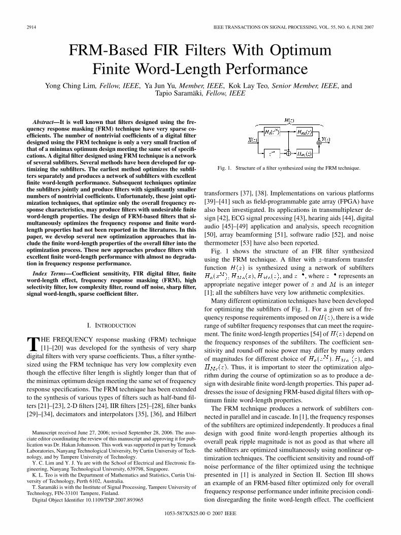
Fig. 1. Structure of a filter synthesized using the FRM technique.
transformers [37], [38]. Implementations on various platforms[39]–[41] such as field-programmable gate array (FPGA) havealso been investigated. Its applications in transmultiplexer de-sign [42], ECG signal processing [43], hearing aids [44], digitalaudio [45]–[49] application and analysis, speech recognition[50], array beamforming [51], software radio [52], and noisethermometer [53] have also been reported.
Fig. 1 shows the structure of an FIR filter synthesizedusing the FRM technique. A filter with -transform transferfunction is synthesized using a network of subfilters
, and , where represents anappropriate negative integer power of and is an integer[1]; all the subfilters have very low arithmetic complexities.
Many different optimization techniques have been developedfor optimizing the subfilters of Fig. 1. For a given set of fre-quency response requirements imposed on , there is a widerange of subfilter frequency responses that can meet the require-ment. The finite word-length properties [54] of depend onthe frequency responses of the subfilters. The coefficient sen-sitivity and round-off noise power may differ by many ordersof magnitudes for different choice of , and
. Thus, it is important to steer the optimization algo-rithm during the course of optimization so as to produce a de-sign with desirable finite word-length properties. This paper ad-dresses the issue of designing FRM-based digital filters with op-timum finite word-length properties.
The FRM technique produces a network of subfilters con-nected in parallel and in cascade. In [1], the frequency responsesof the subfilters are optimized independently. It produces a finaldesign with good finite word-length properties although itsoverall peak ripple magnitude is not as good as that where allthe subfilters are optimized simultaneously using nonlinear op-timization techniques. The coefficient sensitivity and round-offnoise performance of the filter optimized using the techniquepresented in [1] is analyzed in Section II. Section III showsan example of an FRM-based filter optimized only for overallfrequency response performance under infinite precision condi-tion disregarding the finite word-length effect. The coefficient
LIM et al.: FRM-BASED FIR FILTERS WITH OPTIMUM FINITE WORD-LENGTH PERFORMANCE 2915
Fig. 2. Frequency responses of the subfilters of Fig. 1.
sensitivity of an FRM-based filter is investigated in Section IV.The investigation leads to a new design approach where thecoefficient sensitivity is used as the objective function foroptimization. This leads to the design of FRM-based filterswith low coefficient sensitivity. An example of a low coefficientsensitivity design is shown in Section V. Based on the principleof minimizing coefficient sensitivity, many approaches, eachleading to a different objective function, may be developed.Two such approaches are presented in Section VI. The effectson the various design approaches on the signal word-lengthrequired to achieve a given signal-to-noise ratio is presented inSection VII.
II. FINITE WORD-LENGTH PERFORMANCE FOR
THE FILTERS OPTIMIZED IN [1]
In general, the frequency responses of the subfilters op-timized separately using the linear optimization techniquesuch as that used in [1] will resemble that shown in Fig. 2.In Fig. 2, , andare the frequency responses of the filters whose -transformtransfer functions are , and ,respectively. It can be seen from the frequency responses that,for most sinusoidal input frequencies within the pass-bandof , the input signal flows through either the path
or the pathsince the pass-bands of is thestop-bands of and viceversa. Input sinusoids with frequencies in the stop-band of
will be rejected by both and. Thus, for subfilters with
frequency responses as shown in Fig. 2, the scenario that twolarge data are subtracted to form a small data (the scenario thatwill lead to a serious finite word-length problem) never occur.
Fig. 3. Frequency response plots for H (e )H (e ); fe �H (e )gH (e ), and H(e ) for an example exhibiting a seriousfinite word-length problem.
III. FINITE WORD-LENGTH PERFORMANCE OF
SUBFILTERS DESIGNED FOR OPTIMAL FREQUENCY
RESPONSE PERFORMANCE
Many powerful nonlinear optimization techniques have beendeveloped for the design of the subfilters. These advanced non-linear optimization techniques jointly optimize all the subfiltersfor obtaining the optimum overall frequency response. The fre-quency response of the overall filter obtained using these non-linear optimization techniques is significantly better than thatobtained by optimizing the subfilters separately using the linearoptimization technique. Unfortunately, even though the filter de-signed using these advanced techniques has good overall fre-quency response under infinite precision arithmetic condition;its finite word-length properties may be undesirable. The path
and the path mayboth have very high gain causing the outputs of and
to be very large. Since the pass-band gain of the filter’soverall frequency response is unity, the very large output signalsof and must have opposite signs so that thesignals cancel each other to form the filter’s final output that hasa comparable magnitude with the input. Since the output signalof the overall filter is obtained from the difference between twolarge signals, for filter designed using the nonlinear optimizationtechnique, the filter exhibits serious finite word-length problem.We shall illustrate this problem by means of an example.
Consider the design of a low-pass filter with band edges atand , respectively. The allowed peak ripple mag-
nitude is 0.01. When the peak ripple magnitude is used as theobjective function for minimization, there are a large numberof minima with almost the same objective function values. Theoptimization algorithm may converge to any one of the minimaif no further criterion is imposed. The frequency responses
, and(with the linear phase term removed), for a typical
solution are shown in Fig. 3. The coefficient values are shownin Table I. The value of in is 9. As can be seen fromTable I, the coefficients of have very large magnitude.
2916 IEEE TRANSACTIONS ON SIGNAL PROCESSING, VOL. 55, NO. 6, JUNE 2007
TABLE ICOEFFICIENT VALUES FOR H (z); H (z), AND H (z) FOR THE FILTERS
WHOSE FREQUENCY RESPONSES ARE SHOWN IN FIG. 3
In Fig. 3, 1E4 and 2E4 represent 10 000 and 20 000, respec-tively. As can be seen from Fig. 3, and
have very large magnitudeand are opposite in sign. The frequency response isobtained from the difference of two large quantities resulting inserious finite word-length problems.
IV. COEFFICIENT SENSITIVITY
We shall investigate the finite word-length properties of thefilters under two headings, namely, coefficient sensitivity andsignal round off noise. The investigation of the round off noiseproperty is deferred to Section VII while this section is devotedto the discussion of the coefficient sensitivity. The frequencyresponse of the overall filter is given by
(1)
Let the th coefficient values of , andbe , and , respectively. In
actual implementation, all coefficient values must be madediscrete since all implementation platforms are finite precision;this introduces round off errors into the coefficient values. Themagnitudes of the errors depend on the multiplier word length.Let the errors introduced into , and be
, and , respectively, when the co-efficient values are rounded. We shall investigate the change in
caused by small values of , and, where denotes “the magnitude of .” Suppose
that , and become
, and , re-spectively, when , and be-come ,
and . We shall assume that, and are sufficiently
small so that , andare small. Thus, we have
(2)
Neglecting the second order error terms, we have
(3)
It can be seen from (3) that the magnitudes of the sensitivitiesof with respect to changes in ,and are ,and , respectively. Thus,
, and shouldbe minimized for good robustness against changes in
, and . Squaring both sides of(3) leads to
(4)
Let denotes the expected value of . Taking theexpected values for both sides of (4) and assuming that
(see Appendix 1), we have
(5)
The frequency response of a linear phase symmet-rical impulse response FIR filter with length and coefficientvalues is given by
(6a)
LIM et al.: FRM-BASED FIR FILTERS WITH OPTIMUM FINITE WORD-LENGTH PERFORMANCE 2917
for even, and given by
(6b)
for odd.Suppose that changing to causes
to change to . Thus
(7a)
for even, and
(7b)
for odd.Assume that for
(8a)
Define the quantity as
(8b)
Define
(9)
From (7), (8), and (9), we have
(10)
Although is a function of for a given filter,for a large number of independent filters is a
constant independent of if has flat spectrum. Thus
(11)
Applying the result of (11), (5) becomes
(12)
where , and are the numbers of coefficients of, and , respectively.
We have
(13)
Define
(14a)
(14b)
(14c)
For and to produce the same phase shiftsso that their outputs can be summed correctly, and
must have the same order [1], i.e., . Ifthey do not have the same order, the lower order transfer func-tion should be preceded and appended with zero valued coef-ficients so that and have the same order andthat and have the same group delay [1].From (12)–(14), we have
(15)
Let
(16)
From (15) and (16), we have
(17)
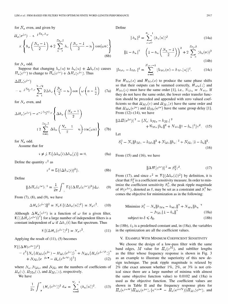
From (17), and since by definition, it isclear that is a coefficient sensitivity measure. In order to min-imize the coefficient sensitivity , the peak ripple magnitudeof , denoted as , may be set as a constraint and be-comes the objective for minimization as in the following:
Minimize
(18a)
subject to (18b)
In (18b), is a predefined constant and, in (18a), the variablesin the optimization are all the coefficient values.
V. EXAMPLE WITH MINIMUM COEFFICIENT SENSITIVITY
We choose the design of a low-pass filter with the sameband edges, value for , and subfilter lengthsas the filter whose frequency response is shown in Fig. 3as an example to illustrate the superiority of this new de-sign technique. The peak ripple magnitude is relaxed by2% (the exact amount whether 1%, 2%, or 3% is not crit-ical since there are a large number of minima with almostthe same objective function value) to 0.0102 and (18a) isused as the objective function. The coefficient values areshown in Table II and the frequency response plots for
, and
2918 IEEE TRANSACTIONS ON SIGNAL PROCESSING, VOL. 55, NO. 6, JUNE 2007
TABLE IICOEFFICIENT VALUES FOR H (z); H (z), AND H (z) FOR
THE FILTER OBTAINED BY MINIMIZING S
Fig. 4. Plots for the various functions for the filter shown in Table II.
(with the linear phase term removed) are shown inFig. 4. The value of is 26.43. It can be seen from Fig. 4that the magnitudes of the gains for and
are not very large; the outputis not obtained from subtracting two large numbers to forma small number and, hence, its finite word-length property isexpected to be much better than that shown in Fig. 3.
The superiority in the coefficient value’s finite word-lengthproperty can be easily demonstrated by evaluating the frequencyresponse subject to coefficient quantization. If the quantizationstep sizes for each coefficient in Table II are 2 and 2 ,the peak ripple magnitudes of the overall filter become 0.01029and 0.01046, respectively. The frequency response plot for thecase where the coefficient quantization step size is 2 , (i.e.,the coefficient values are obtained by multiplying them by 2 ,
Fig. 5. Frequency response plot for the filter in Table II with coefficient quan-tization step size = 2 .
TABLE IIISUMMARY OF THE COMPARISONS BETWEEN THE FILTERS OF TABLES I AND II
rounded to the nearest integer, and then divided by 2 ) is shownin Fig. 5.
For the purpose of comparison, the value of(i.e., the equiva-
lent value) for the filter whose coefficients are shown inTable I is 6.78 10 . High coefficient sensitivity is expected. Toachieve a peak ripple magnitude of about 0.0103 the coefficientquantization step size for the filter shown in Table I shouldnot be larger than 2 . Specifically, if the quantization stepsize for the coefficients of is 2 and that ofand are 2 , the peak ripple magnitude is 0.01034.It is interesting to note that the requirement on the relativeprecision for the coefficients of for the filter shownin Table I and that shown in Table II are roughly the same butthe requirement on the relative precision for the coefficientsof and for the filter shown in Table I andthat shown in Table II differ by about 10 . This is not sur-prising since the ratio of their respective values of is about10 . A summary of thecomparisons between the filter of Table I and that of Table IIis shown in Table III.
The greatly improved coefficient sensitivity is achieved withalmost no penalty in frequency response performance. This isbecause the objective function has many minima with insignif-icant difference in peak ripple magnitude. If the value of in(18b) is set close to (say within 2% from) the optimum solutionobtained in minimizing without taking coefficient sensitivityinto consideration, minimizing (18a) simply produces a solutionwith excellent coefficient sensitivity without noticeable degra-dation in frequency response performance.
LIM et al.: FRM-BASED FIR FILTERS WITH OPTIMUM FINITE WORD-LENGTH PERFORMANCE 2919
Fig. 6. Frequency response plots for the various components of the right-sideof (12) for the filter shown in Table II.
VI. COEFFICIENT SENSITIVITY AS A FUNCTION OF FREQUENCY
If the coefficient quantization step size is , (17) may berewritten as [54]
(19)
From (9) and (19), we have
(20)
Equation (20) provides useful statistic for the frequency re-sponse deviation due to coefficient quantization. Expressionfor is given in (12). In order to have a betterunderstanding of the function , we plot inFig. 6 the various components in the right-hand side of (12)constituting for the filter of Table II.
It can be seen from Fig. 6 that
peaks at around thetransition band, i.e., the frequency response at the frequencyband near the transition is most sensitive to coefficientquantization. In this particular example, the largest contributoris the term. However, thelargest contributor depends on the specific example. Forthe filter shown in Table I, the largest contributors are the
and terms.The previous observations lead to the following new ap-
proaches in obtaining a low coefficient sensitivity design.One of these approaches is to relax the peak frequency re-
sponse ripple magnitude from its optimum value by a smallamount (say 2%) and minimize the peak of
i.e., let
(21)
and the objective function is
(22)
where is the maximum value of overall and the variables in the optimization are all the co-efficient values. Depending on the optimization packageused, minimizing may be achieved by minimizing
over a dense grid of , where is a large positiveinteger.
There are other possibilities. It can be seen from(5) that , and
are the sensitivity measures ofwith respect to changes in ,
and , respectively. The maximum of the peakvalues of , and
may be minimized. Define
(23a)
(23b)
(23c)
The objective function is
minimize maximum of
(24)
The variables in the optimization are all the coefficient values.Depending on the optimization package used, minimizing themaximum of may beachieved by minimizing
over a dense grid of where is a large positiveinteger.
Our experience shows that the minimiza-tion of , or the maximum of
all lead tofilters with excellent coefficient sensitivities; their differencesin coefficient sensitivity is insignificant. The actual approachthat should be adopted depends on other factors such asavailability and robustness of optimization packages, hardwareimplementation platform for the resulting filter, and etc.
The coefficient values for a design obtainedby minimizing are shown inTable IV and the frequency response plots for
, andare shown in Fig. 7. Its equivalent value (i.e., its
value) is29.02. The peak value for
is 75.71.The various components in the right-hand side of (12)constituting are plotted in Fig. 8. If thequantization step size for the coefficients of is 2and that of and are 2 , the peak ripple
2920 IEEE TRANSACTIONS ON SIGNAL PROCESSING, VOL. 55, NO. 6, JUNE 2007
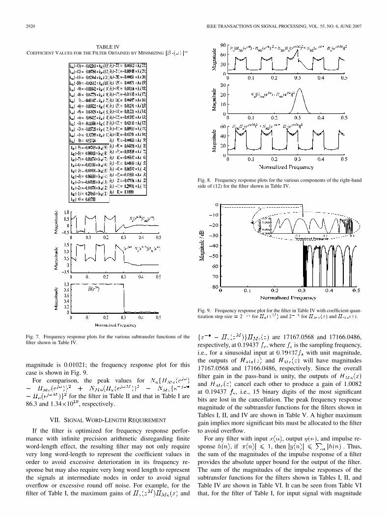
TABLE IVCOEFFICIENT VALUES FOR THE FILTER OBTAINED BY MINIMIZING kS (!)k
Fig. 7. Frequency response plots for the various subtransfer functions of thefilter shown in Table IV.
magnitude is 0.01021; the frequency response plot for thiscase is shown in Fig. 9.
For comparison, the peak values for
for the filter in Table II and that in Table I are86.3 and 1.34 10 , respectively.
VII. SIGNAL WORD-LENGTH REQUIREMENT
If the filter is optimized for frequency response perfor-mance with infinite precision arithmetic disregarding finiteword-length effect, the resulting filter may not only requirevery long word-length to represent the coefficient values inorder to avoid excessive deterioration in its frequency re-sponse but may also require very long word length to representthe signals at intermediate nodes in order to avoid signaloverflow or excessive round off noise. For example, for thefilter of Table I, the maximum gains of and
Fig. 8. Frequency response plots for the various components of the right-handside of (12) for the filter shown in Table IV.
Fig. 9. Frequency response plot for the filter in Table IV with coefficient quan-tization step size = 2 for H (z ) and 2 for H (z) and H (z).
are 17167.0568 and 17166.0486,respectively, at 0.19437 , where is the sampling frequency,i.e., for a sinusoidal input at with unit magnitude,the outputs of and will have magnitudes17167.0568 and 17166.0486, respectively. Since the overallfilter gain in the pass-band is unity, the outputs ofand cancel each other to produce a gain of 1.0082at 0.19437 , i.e., 15 binary digits of the most significantbits are lost in the cancellation. The peak frequency responsemagnitude of the subtransfer functions for the filters shown inTables I, II, and IV are shown in Table V. A higher maximumgain implies more significant bits must be allocated to the filterto avoid overflow.
For any filter with input , output , and impulse re-sponse , if , then . Thus,the sum of the magnitudes of the impulse response of a filterprovides the absolute upper bound for the output of the filter.The sum of the magnitudes of the impulse responses of thesubtransfer functions for the filters shown in Tables I, II, andTable IV are shown in Table VI. It can be seen from Table VIthat, for the filter of Table I, for input signal with magnitude
LIM et al.: FRM-BASED FIR FILTERS WITH OPTIMUM FINITE WORD-LENGTH PERFORMANCE 2921
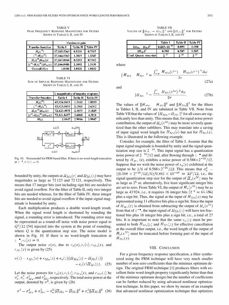
TABLE VPEAK FREQUENCY RESPONSE MAGNITUDES FOR FILTERS
SHOWN IN TABLES I, II, AND IV
TABLE VISUM OF IMPULSE RESPONSE MAGNITUDES FOR FILTERS
SHOWN IN TABLES I, II, AND IV
Fig. 10. Noisemodel for FRM-based filter. If there is no word-length truncationat z ; e (z) = 0.
bounded by unity, the outputs at and may havemagnitudes as large as 72 123 and 72 121, respectively. Thismeans that 17 integer bits (not including sign bit) are needed toavoid signal overflow. For the filter of Table II, only two integerbits are needed whereas, for the filter of Table IV, three integerbits are needed to avoid signal overflow if the input signal mag-nitude is bounded by unity.
Each multiplication produces a double word-length result.When the signal word length is shortened by rounding thesignal, a rounding error is introduced. The rounding error maybe represented as a round-off noise with noise power equal to
[54] injected into the system at the point of rounding,where is the quantization step size. The noise model isshown in Fig. 10. If there is no word-length truncation at
.The output noise , due to , and
is given by (25)
(25)
Let the noise powers for , and be, and , respectively. The total noise power at the
output, denoted by , is given by (26)
(26)
TABLE VIIVALUES OF kH � H k AND kH k FOR FILTERS
SHOWN IN TABLES I, II, AND IV
where
(27a)
and
(27b)
The values of and for the filtersin Tables I, II, and IV are tabulated in Table VII. Note fromTable VII that the values of for all cases are sig-nificantly less than unity. This means that, for equal noise powercontribution, the output of may be more severely quan-tized than the other subfilters. This may translate into a savingof input signal word length for but not for .This is illustrated in the following example.
Consider, for example, the filter of Table I. Assume that theinput signal magnitude is bounded by unity and the signal quan-tization step size is 2 . This input signal has a quantizationnoise power of 2 and, after flowing through and fil-tered by (z), exhibits a noise power of 0.588 2 .Suppose that we wish the noise power of exhibited at theoutput to be of 0.588 2 . This means that
, i.e., thesignal quantization step size for the output of may beas large as 2 or, alternatively, five least significant integer bitsare set to zero. From Table VI, the output of may be aslarge as 43 924, i.e., it requires 16 integer bitsplus a sign bit. Thus, the signal at the input of may berepresented using 11 effective bits plus a sign bit. Since the inputof is obtained from subtracting the output offrom that of , the input signal of will have ten frac-tional bits plus 16 integer bits plus a sign bit, i.e., a total of 27bits. It is important to note that the same must be pre-sented to both and for effective cancellationat the overall filter output, i.e., the word length of the output of
must be truncated before forming part of the input of.
VIII. CONCLUSION
For a given frequency response specification, a filter synthe-sized using the FRM technique will have very much smallernumber of non-zero coefficients than the minimax optimum de-sign. The original FRM technique [1] produces filters with ex-cellent finite word-length property (significantly better than thatof the minimax optimum design) but the number of coefficientscan be further reduced by using advanced nonlinear optimiza-tion technique. In this paper, we show by means of an examplethat advanced nonlinear optimization technique that optimizes
2922 IEEE TRANSACTIONS ON SIGNAL PROCESSING, VOL. 55, NO. 6, JUNE 2007
the overall frequency response disregarding finite word-lengthproperties may produce filters that have very high coefficientsensitivity and require very long signal word length. In orderto overcome this shortcoming, in this paper, we present severaltechniques in (18a), (22), and (24), respectively, that include co-efficient sensitivity measures into the objective function for op-timization. These techniques produce filters with excellent finiteword-length properties.
The computing resources required and convergent propertiesof the new techniques do not differ significantly from the con-ventional technique. The actual computing resources requiredand convergent properties depend on the optimization packageused. The optimization package we used always converges but,unfortunately, it is easily trapped in local optimum solution. Weovercome the problem by initiating the optimization process atdifferent initial solutions. The development of an optimizationpackage that is not easily trapped in local optimum solution willbe the next challenge.
The optimal low sensitivity design will be a good initial so-lution for further research in low complexity designs such asminimum shift-and-add design.
APPENDIX I
We have
and
Thus
since
Similarly, it can be shown that
REFERENCES
[1] Y. C. Lim, “Frequency-response masking approach for the synthesisof sharp linear phase digital filter,” IEEE Trans. Circuits Syst., vol.CAS-33, no. 4, pp. 357–364, Apr. 1986.
[2] G. Rajan, Y. Neuvo, and S. K. Mitra, “On the design of sharp cutoffwideband fir filters with reduced arithmetic complexity,” IEEE Trans.Circuits Syst., vol. 35, no. 11, pp. 1447–1454, Nov. 1988.
[3] Y. C. Lim and Y. Lian, “The optimum design of one- and two-dimen-sional FIR filters using the frequency response masking technique,”IEEE Trans. Circuits Syst. II, vol. CAS-40, no. 2, pp. 88–95, Feb. 1993.
[4] J. H. Lee and C. K. Chen, “Design of sharp FIR filters with prescribedgroup delay,” in Proc. IEEE Int. Symp. Circuits Syst., 1993, pp. 92–95.
[5] Y. C. Lim and Y. Lian, “Frequency-response masking approach fordigital filter design: Complexity reduction via masking filter factoriza-tion,” IEEE Trans. Circuits Syst. II, Analog Digit. Signal Process., vol.41, no. 8, pp. 518–525, Aug. 1994.
[6] M. G. Bellanger, “Improved design of long FIR filters using the fre-quency masking technique,” in Proc. IEEE Int. Conf. Acoust. SpeechSignal Process., 1996, pp. 1272–1275.
[7] L. C. R. Barcellos, S. L. Netto, and P. S. R. Diniz, “Optimization ofFRM filters using the WLS-Chebyshev approach,” Circuits Syst. SignalProcess., vol. 22, no. 2, pp. 99–113, Mar./Apr. 2003.
[8] T. Saramäki and Y. C. Lim, “Use of the Remez algorithm for designingFRM based FIR filters,” Circuits Syst. Signal Process., vol. 22, no. 2,pp. 77–97, Mar./Apr. 2003.
[9] W. S. Lu and T. Hinamoto, “Optimal design of frequency-response-masking filters using semidefinite programming,” IEEE Trans. CircuitsSyst. I, Fundam. Theory Appl., vol. 50, no. 4, pp. 557–568, Apr. 2003.
[10] Y. Lian and C. Z. Yang, “Complexity reduction by decoupling themasking filters from bandedge shaping filter in FRM technique,” Cir-cuits Syst. Signal Process., vol. 22, no. 2, pp. 115–135, Mar./Apr. 2003.
[11] Y. Lian, “Complexity reduction for FRM based FIR filters using theprefilter-equalizer technique,” Circuits Syst. Signal Process., vol. 22,no. 2, pp. 137–155, Mar./Apr. 2003.
[12] T. Saramäki, J. Yli-Kaakinen, and H. Johansson, “Optimization of fre-quency-response-masking based fir filters,” Circuits Syst. Comput., vol.12, no. 5, pp. 563–590, Oct. 2003.
[13] W. R. Lee, V. Rehbock, and K. L. Teo, “Frequency-responsemasking based FIR filter design with power-of-two coefficientsand suboptimum PWR,” Circuits Syst. Comput., vol. 12, no. 5,pp. 591–600, Oct. 2003.
[14] O. Gustafsson, H. Johansson, and L. Wanhammar, “Single filter fre-quency-response masking FIR filter,” Circuits Syst. Comput., vol. 12,no. 5, pp. 601–630, Oct. 2003.
[15] W. S. Lu and T. Hinamoto, “Optimal design of IIR frequency-response-masking filters using second-order cone programming,” IEEE Trans.Circuits Syst. I, Fundam. Theory Appl., vol. 50, no. 11, pp. 1401–112,Nov. 2003.
[16] W. R. Lee, V. Rehbock, K. L. Teo, and L. Caccetta, “A weightedleast-square-based approach to FIR filter design using the frequency-response masking technique,” IEEE Signal Process. Lett., vol. 11, no.7, pp. 593–596, Jul. 2004.
[17] A. Usman and S. A. Khan, “Simulation of frequency response maskingapproach for FIR filter design,” WSEAS Trans. Syst., vol. 3, no. 10, pp.2919–2924, Dec. 2004.
[18] Y. J. Yu, K. L. Teo, Y. C. Lim, and G. H. Zhao, “Extrapolated impulseresponse filter and its application in the synthesis of digital filters usingthe frequency-response masking technique,” Signal Process., vol. 50,pp. 581–590, Mar. 2005.
[19] J. X. Rodrigues and K. R. Pai, “Modified linear phase frequencyresponse masking FIR filter,” in Proc. 4th Int. Symp. Image SignalProcess. Analy., 2005, pp. 434–439.
[20] L. Cen and Y. Lian, “Hybrid genetic algorithm for the design of mod-ified frequency-response masking filters in a discrete space,” Circuits,Syst., Signal Process., vol. 25, no. 2, pp. 153–174, Apr. 2006.
[21] T. Saramäki, Y. C. Lim, and R. Yang, “The synthesis of half-band filterusing frequency-response masking technique,” IEEE Trans. CircuitsSyst. II, Analog Digit. Signal Process., vol. 42, no. 1, pp. 58–60, Jan.1995.
[22] Y. Lian, “The optimum design of half-band filter using multi-stagefrequency-response masking technique,” Signal Process., vol. 44, pp.369–372, July 1995.
[23] C. T. Thia and Y. Lian, “The implementation of a high-speed 645-TAPequivalent half-band FIR filter using the frequency response maskingtechnique,” in Proc. IEEE TENCON, 2004, pp. 13–16.
[24] Y. C. Lim and S. H. Low, “Frequency-response masking approach forthe synthesis of sharp two-dimensional diamond-shaped filters,” IEEETrans. Circuits Syst. II, Analog Digit. Signal Process., vol. 45, no. 12,pp. 1573–1584, Dec. 1998.
[25] H. Johansson and L. Wanhammar, “High-speed recursive digital filtersbased on the frequency-response masking approach,” IEEE Trans. Cir-cuits Syst. II, Analog Digit. Signal Process., vol. 47, no. 1, pp. 48–61,Jan. 2000.
[26] M. D. Lutovac and L. D. Milic, “IIR filters based on frequency-re-sponse masking approach,” in Proc. 5th Int. Conf. Telecommun.Modern Satellite, Cable Broadcasting Service, 2001, pp. 163–70.
[27] O. Gustafsson, H. Johansson, and L. Wanhammar, “Single filterfrequency masking high-speed recursive digital filters,” Circuits Syst.Signal Process., vol. 22, no. 2, pp. 219–238, Mar./Apr. 2003.
LIM et al.: FRM-BASED FIR FILTERS WITH OPTIMUM FINITE WORD-LENGTH PERFORMANCE 2923
[28] H. H. Chen, S. C. Chan, and K. L. Ho, “A semi-definite programming(SDP) method for designing IIR sharp cut-off digital filters using fre-quency-response masking,” in Proc. IEEE Int. Symp. Circuits Syst.,2004, pp. III-149–III-152.
[29] J. W. Lee and Y. C. Lim, “Efficient implementation of real filterbanks using frequency response masking techniques,” in Proc. IEEEAsia–Pacific Conf. Circuits Syst., 2002, pp. 69–72.
[30] L. Rosenbaum, P. Lowenborg, and H. Johansson, “Cosine andsine modulated FIR filter banks utilizing the frequency-responsemasking approach,” in Proc. IEEE Int. Symp. Circuits Syst., 2003, pp.III-882–III-885.
[31] H. Johansson and T. Saramäki, “Two-channel FIR filter banks utilizingthe FRM approach,” Circuits Syst. Signal Process., vol. 22, no. 2, pp.157–192, Mar./Apr. 2003.
[32] M. B. Furtado, P. S. R. Diniz, and S. L. Netto, “Optimized prototypefilter based on the FRM approach for cosine-modulated filter banks,”Circuits Syst. Signal Process., vol. 22, no. 2, pp. 193–210, Mar./Apr.2003.
[33] S. L. Netto, L. C. R. Barcellos, and P. S. R. Diniz, “Efficient designof narrowband cosine-modulated filter banks using a two-stage fre-quency-response masking approach,” Circuits Syst. Comput., vol. 12,no. 5, pp. 631–642, Oct. 2003.
[34] R. Bregovic and T. Saramaki, “Design of two-channels FIR filterbankswith rational sampling factors using the FRM technique,” in Proc. IEEEInt. Symp. Circuits Syst., 2005, pp. 1098–1101.
[35] Y. C. Lim and R. Yang, “On the synthesis of very sharp decimators andinterpolators using the frequency-response masking technique,” IEEETrans. Signal Process., vol. 53, no. 4, pp. 1387–1397, Apr. 2005.
[36] H. Johansson, “Two classes of frequency-response maskinglinear-phase FIR filters for interpolation and decimation,” Cir-cuits Syst. Signal Process., vol. 25, no. 2, pp. 175–200, Apr. 2006.
[37] Y. C. Lim and Y. J. Yu, “Synthesis of very sharp Hilbert transformerusing the frequency-response masking technique,” IEEE Trans. SignalProcess., vol. 53, pp. 2595–2597, Jul. 2005.
[38] Y. C. Lim, Y. J. Yu, and T. Saramaki, “Optimum masking levelsand coefficient sparseness for Hilbert transformers and half-bandfilters designed using the frequency-response masking technique,”IEEE Trans. Circuits Syst. I, Reg. Papers, vol. 52, no. 11, pp.2444–2453, Nov. 2005.
[39] Y. C. Lim, Y. J. Yu, H. Q. Zheng, and S. W. Foo, “FPGAimplementation of digital filters synthesized using the FRM technique,”Circuits Syst. Signal Process., vol. 22, no. 2, pp. 211–218, Mar./Apr.2003.
[40] Y. Lian, “A modified frequency response masking structure for high-speed FPGA implementation of programmable sharp FIR filters,” Cir-cuits Syst. Comput., vol. 12, no. 5, pp. 643–654, Oct. 2003.
[41] W. Boonkumklao, Y. Miyanaga, and K. Dejhan, “A flexible architec-ture for digital signal processing,” IEICE Trans. Inf. Syst., pt. E86D,pp. 2179–2186, Oct. 2003.
[42] P. S. R. Diniz, L. C. R. de Barcellos, and S. L. Netto, “Design ofhigh-resolution cosine-modulated transmultiplexers with sharp transi-tion band,” IEEE Trans. Signal Process., vol. 52, pp. 1278–1288, May2004.
[43] Y. Lian and J. H. Yu, “The reduction of noises in ECG signal using afrequency response masking based FIR filter,” in Proc. IEEE Int. Work-shop Biomed. Circuits Syst., 2004, pp. S2/4-17–S2/4-20.
[44] Y. Lian and Y. Wei, “A computationally efficient nonuniform FIR dig-ital filter bank for hearing aids,” IEEE Trans. Circuits Syst. I, Reg. Pa-pers, vol. 52, no. 12, pp. 2754–2762, Dec. 2005.
[45] Y. C. Lim, “A digital filter bank for digital audio systems,” IEEE Trans.Circuits Syst., vol. CAS-33, no. 8, pp. 848–849, Aug. 1986.
[46] R. H. Yang, S. B. Chiah, and W. Y. Chan, “Design and implementationof a digital audio tone control unit using an efficient FIR filter struc-ture,” in Proc. IEEE Region 10 Annu. Int. Conf., 1996, pp. 273–277.
[47] C. S. Lin and C. Kyriakakis, “Frequency response masking approachfor designing filter banks with rational sampling factors,” in Proc. IEEEWorkshop Appl. Signal Process. Audio Acoust., 2003, pp. 99–102.
[48] S. W. Foo and W. T. Lee, “Application of fast filter bank for transcrip-tion of polyphonic signals,” Circuits Syst. Comput., vol. 12, no. 5, pp.654–674, Oct. 2003.
[49] S. W. Foo and W. T. Lee, “Recognition of piano notes with the aid ofFRM filters,” in Proc. Int. Symp. Control, Commun. Signal Process.,2004, pp. 409–413.
[50] N. Hayasaka, N. Wada, S. Yoshizawa, and Y. Miyanaga, “A robustspeech recognition system using FRM running spectrum filtering,”in Proc. Int. Symp. Control, Commun. Signal Process., 2004, pp.401–404.
[51] Y. Liu and Z. Lin, “On the applications of the frequency-responsemasking technique in array beamforming,” Circuits, Syst. SignalProcess., vol. 25, no. 2, pp. 201–224, Apr. 2006.
[52] Y. Zhang, W. Wu, and B. Tian, “A novel sharp-cutoff FIR filter de-sign technique and its application in software radio,” in Proc. Int. Conf.Commun. Technol., 2003, pp. 1821–1829.
[53] H. Saleh, E. Zimmermann, G. Brandenburg, and H. Halling, “Effi-cient FPGA-based multistage two-path decimation filter for noise ther-mometer,” in Proc. 13th Int. Conf. Microelectron., 2001, pp. 161–164.
[54] L. R. Rabiner and B. Gold, Theory and Application of Digital SignalProcessing. Englewood Cliffs, NJ: Prentice-Hall, 1975, ch. 5, pp.295–355.
Yong Ching Lim (S’80–M’80–SM’92–F’00) re-ceived the A.C.G.I., B.Sc., D.I.C., and Ph.D. degrees,all in electrical engineering, from Imperial College,University of London, U.K., in 1977, 1977, 1980,and 1980, respectively.
Since 2003, he has been with the School of Elec-trical and Electronic Engineering, Nanyang Techno-logical University, Singapore, where he is currently aProfessor. From 1980 to 1982, he was a National Re-search Council Research Associate in the Naval Post-graduate School, Monterey, CA. From 1982 to 2003,
he was with the Department of Electrical Engineering, National University ofSingapore. His research interests include digital signal processing and VLSI cir-cuits and systems design.
Dr. Lim was a recipient of the 1996 IEEE Circuits and Systems Society’sGuillemin-Cauer Award, the 1990 IREE (Australia) Norman Hayes MemorialAward, the 1977 IEE (UK) Prize, and the 1974–1977 Siemens Memorial (Impe-rial College) Award. He served as a lecturer for the IEEE Circuits and SystemsSociety under the distinguished lecturer program from 2001 to 2002 and as anAssociate Editor for the IEEE TRANSACTIONS ON CIRCUITS AND SYSTEMS from1991 to 1993 and from 1999 to 2001. He has also served as an Associate Editorfor Circuits, Systems and Signal Processing from 1993 to 2000. He served as theChairman of the DSP Technical Committee of the IEEE Circuits and SystemsSociety from 1998 to 2000. He served in the Technical Program Committee’sDSP Track as Track Chairman in IEEE ISCAS’97 and IEEE ISCAS’00 and asa Track Co-chairman in IEEE ISCAS’99. He is the General Chairman for IEEEAPCCAS’06. He is a member of Eta Kappa Nu.
Ya Jun Yu (S’99–M’05) received the B.Sc. andM.Eng. degrees in biomedical engineering fromZhejiang University, Hangzhou, China, in 1994 and1997, respectively, and the Ph.D. degree in electricaland computer engineering from the National Univer-sity of Singapore, Singapore, in 2004.
Since 2005, she has been with the School ofElectrical and Electronic Engineering, NanyangTechnological University, Singapore, where sheis currently an Assistant Professor. From 1997 to1998, she was a Teaching Assistant with Zhejiang
University. She joined the Department of Electrical and Computer Engineering,National University of Singapore as a Post Master Fellow in 1998 and remainedin the same department as a Research Engineer until 2004. In 2002, she wasa visiting Researcher at the Tampere University of Technology, Tampere,Finland, and The Hong Kong Polytechnic University, Hong Kong, China.She joined the Temasek Laboratories at Nanyang Technological Universityas a Research Fellow in 2004. Her research interests include digital signalprocessing and VLSI circuits and systems design.
Kok Lay Teo (M’74–SM’87) received the B.Sc. de-gree in telecommunications engineering from NgeeAnn Technical College, Singapore, and the M.A.Scand Ph.D. degrees in electrical engineering from theUniversity of Ottawa, Ottawa, ON, Canada.
He is currently Chair of Applied Mathematics andHead of the Department of Mathematics and Statis-tics, Curtin University of Technology, Australia. Hewas with the Department of Applied Mathematics,University of New South Wales, Australia, the De-partment of Industrial and Systems Engineering, Na-
2924 IEEE TRANSACTIONS ON SIGNAL PROCESSING, VOL. 55, NO. 6, JUNE 2007
tional University of Singapore, Singapore, the Department of Mathematics, theUniversity of Western Australia, Australia. In 1996, he joined the Department ofMathematics and Statistics, Curtin University of Technology, as a Professor. Hethen took up the position of Chair Professor of Applied Mathematics and Headof Department of Applied Mathematics at the Hong Kong Polytechnic Univer-sity, Hong Kong, China, from 1999 to 2004. His research interests include boththe theoretical and practical aspects of optimal control and optimization, andtheir practical applications such as in signal processing, telecommunications,and financial portfolio optimization. He has published five books and over 300journal papers. He has a software package, MISERS.3, for solving general con-strained optimal control problems. He is Editor-in-Chief of the Journal of Indus-trial and Management Optimization. He also serves as an Associate Editor ofa number of international journals, including Automatica, Nonlinear Dynamicsand Systems Theory, Journal of Global Optimization, Engineering and Opti-mization, Discrete and Continuous Dynamic Systems (Series A and Series B),Dynamics of Continuous, and Discrete and Impulsive Systems (Series A and Se-ries B).
Tapio Saramäki (M’98–SM’01–F’02) was born inOrivesi, Finland, on June 12, 1953. He received theDiploma Engineer (with honors) and the Doctor ofTechnology (with honors) degrees in electrical engi-neering from the Tampere University of Technology(TUT), Tampere, Finland, in 1978 and 1981, respec-tively.
Since 1977, he has held various research andteaching positions at TUT, where he is currentlya Professor of Signal Processing and a Docent ofTelecommunications. He is also a co-founder and a
system-level designer of VLSI Solution Oy, Tampere, Finland, specializing inefficient VLSI implementations of both analog and digital signal processingalgorithms for various applications. He is also the President of Aragit Oy Ltd.,Tampere, Finland, which was founded by four TUT professors and concentrateson spreading worldwide their know-how on information technology to theindustry. In 1982, 1985, 1986, 1990, and 1998 he was a Visiting ResearchFellow with the University of California, Santa Barbara, and in 1987 with theCalifornia Institute of Technology, Pasadena, and in 2001, with the NationalUniversity of Singapore. He has written more than 250 international journaland conference articles, various international book chapters, and holds threeworldwide-used patents. His research interests are in digital signal processing,especially filter and filter bank design, VLSI implementations, and communi-cations applications, as well as approximation and optimization theories.
Dr. Saramäki was a recipient of the 1987 and 2007 IEEE Circuits and Sys-tems Society’s Guillemin-Cauer Award as well as two other Best Paper Awards.In 2004, he was also awarded the honorary membership (Fellow) of the A. S.Popov Society for Radio-Engineering, Electronics, and Communications (thehighest membership grade in the society and the 80th honorary member since1945) for “great contributions to the development of DSP theory and methodsand great contributions to the consolidation of relationships between Russianand Finnish organizations.” He is also a founding member of the Median-FreeGroup International. He was an Associate Editor for the IEEE TRANSACTIONS
ON CIRCUITS AND SYSTEMS: ANALOG AND DIGITAL SIGNAL PROCESSING from2000 to 2001, and is currently an Associate Editor for Circuits, Systems, andSignal Processing. He has been actively taking part in many duties in the IEEECircuits and Systems Society’s DSP Committee, namely by being a Chairman(2002–2004), a Distinguished Lecturer (2002–2003), a Tract or a Co-TrackChair for many ISCAS symposiums (2003-2005). In addition, he has beenone of the three chairmen of the annual workshop on Spectral Methods andMultirate Signal Processing (SMMSP), started in 2001.