From Requirements via Colored Workflow Nets to an Implementation in Several Workflow Systems R.S. Mans 1 , W.M.P. van der Aalst 1 , P.J.M. Bakker 2 , A.J. Moleman 2 , K.B. Lassen 3 and J.B. Jørgensen 3 1 Department of Information Systems, Eindhoven University of Technology, P.O. Box 513, NL-5600 MB, Eindhoven, The Netherlands. {r.s.mans,w.m.p.v.d.aalst}@tue.nl 2 Academic Medical Center, University of Amsterdam, Department of Innovation and Process Management, Amsterdam, The Netherlands. {p.j.bakker,a.j.moleman}@amc.uva.nl 3 Department of Computer Science, University of Aarhus, IT-parken, Aabogade 34, DK-8200 Aarhus N, Denmark. {krell,jbj}@daimi.au.dk Abstract. Care organizations, such as hospitals, need to support complex and dynamic workflows. More- over, many disciplines are involved. This makes it important to avoid the typical disconnect between requirements and the actual implementation of the system. This paper proposes an approach where an Executable Use Case (EUC) and Colored Workflow Net (CWN) are used to close the gap between the given requirements specification and the realization of these requirements with the help of a workflow system. This paper describes a large case study where the diagnostic trajectory of the gynaecological oncology care process of the Academic Medical Center (AMC) hospital is used as reference process. The process consists of hundreds of activities. These have been modeled and analyzed using an EUC and a CWN. Moreover, based on the CWN, the process has been implemented using four different workflow systems. This shows the applicability of our approach and allows for an evaluation of different approaches towards flexibility in workflow systems. 1 Introduction For some time now, especially in academic hospitals, there has been a need for support in controlling and monitoring health care processes for patients [29]. In general, there is the need to support the diagnostic and therapeutic trajectory of health care processes. One of the objectives of hospitals is to increase the quality of care for patients [16]. However, what we also see is that on the governmental side and on the side of the health insurance companies, more and more pressure is put on hospitals to work in the most efficient way as possible. Moreover, in the future, an increase in the demand for care is expected. Workflow technology can be seen as an interesting vehicle for the support and monitoring of health care processes. Workflow Management Systems (WfMS) support processes by managing the flow of work such that the work is done at the right time by the proper person [3]. Advantages of successfully applying workflow technology are that processes supported by workflow systems can be executed faster and more efficiently. In addition, processes can be monitored, which has also as consequence that processes can be executed faster. The difficulties that hospitals have to cope with when they want to support their health care processes, and the need for supporting their health care processes emerges from the fact that healthcare processes are diverse, flexible and that several specialties can be involved in the treatment process. So, what we find is that, for example, for a group of patients with the same diagnosis, the number of different examinations and treatments can be high and the order in which they are done can vary greatly. Also, because of intermediary results of diagnostic examinations, the way a patient reacts to the offered treatment, and the condition of the patient itself, it may be necessary to continuously adapt the care process for a particular patient [14]. Actually, there is a large gap between a running hospital process and its implementation in different workflow systems. The main focus of this paper is to present the steps we took to bridge this gap. Moreover, we will also explicitly focus on how and when we used the formal modeling language Colored Petri Nets (CPNs)[20, 27] in the steps that we took.
Transcript
From Requirements via Colored Workflow Nets to anImplementation in Several Workflow Systems
R.S. Mans1, W.M.P. van der Aalst1, P.J.M. Bakker2, A.J. Moleman2, K.B. Lassen3 and J.B. Jørgensen3
1 Department of Information Systems, Eindhoven University of Technology, P.O. Box 513, NL-5600 MB, Eindhoven,The Netherlands. {r.s.mans,w.m.p.v.d.aalst}@tue.nl
2 Academic Medical Center, University of Amsterdam, Department of Innovation and Process Management,Amsterdam, The Netherlands. {p.j.bakker,a.j.moleman}@amc.uva.nl
3 Department of Computer Science, University of Aarhus, IT-parken, Aabogade 34, DK-8200 Aarhus N, Denmark.{krell,jbj}@daimi.au.dk
Abstract. Care organizations, such as hospitals, need to support complex and dynamic workflows. More-over, many disciplines are involved. This makes it important to avoid the typical disconnect betweenrequirements and the actual implementation of the system. This paper proposes an approach where anExecutable Use Case (EUC) and Colored Workflow Net (CWN) are used to close the gap between thegiven requirements specification and the realization of these requirements with the help of a workflowsystem. This paper describes a large case study where the diagnostic trajectory of the gynaecologicaloncology care process of the Academic Medical Center (AMC) hospital is used as reference process. Theprocess consists of hundreds of activities. These have been modeled and analyzed using an EUC and aCWN. Moreover, based on the CWN, the process has been implemented using four different workflowsystems. This shows the applicability of our approach and allows for an evaluation of different approachestowards flexibility in workflow systems.
1 Introduction
For some time now, especially in academic hospitals, there has been a need for support in controlling andmonitoring health care processes for patients [29]. In general, there is the need to support the diagnostic andtherapeutic trajectory of health care processes.
One of the objectives of hospitals is to increase the quality of care for patients [16]. However, what we alsosee is that on the governmental side and on the side of the health insurance companies, more and more pressureis put on hospitals to work in the most efficient way as possible. Moreover, in the future, an increase in thedemand for care is expected.
Workflow technology can be seen as an interesting vehicle for the support and monitoring of health careprocesses. Workflow Management Systems (WfMS) support processes by managing the flow of work such thatthe work is done at the right time by the proper person [3]. Advantages of successfully applying workflowtechnology are that processes supported by workflow systems can be executed faster and more efficiently. Inaddition, processes can be monitored, which has also as consequence that processes can be executed faster.
The difficulties that hospitals have to cope with when they want to support their health care processes, andthe need for supporting their health care processes emerges from the fact that healthcare processes are diverse,flexible and that several specialties can be involved in the treatment process. So, what we find is that, forexample, for a group of patients with the same diagnosis, the number of different examinations and treatmentscan be high and the order in which they are done can vary greatly. Also, because of intermediary results ofdiagnostic examinations, the way a patient reacts to the offered treatment, and the condition of the patientitself, it may be necessary to continuously adapt the care process for a particular patient [14].
Actually, there is a large gap between a running hospital process and its implementation in different workflowsystems. The main focus of this paper is to present the steps we took to bridge this gap. Moreover, we will alsoexplicitly focus on how and when we used the formal modeling language Colored Petri Nets (CPNs)[20, 27] inthe steps that we took.
Real world (healthcare process)
Interviews with users
Requirements model
Executable Use Cases (EUCs)(CPN + animation)
Specification model
Colored Workflow Net (CWN)(CPN)
YAWL
FLOWer
ADEPT1
Declare
Implementation
focus on context (processes, resources, data, systems, decisions)
focus on realization (system and software)
insights
insights
insights
analysis
insights
insights
insights
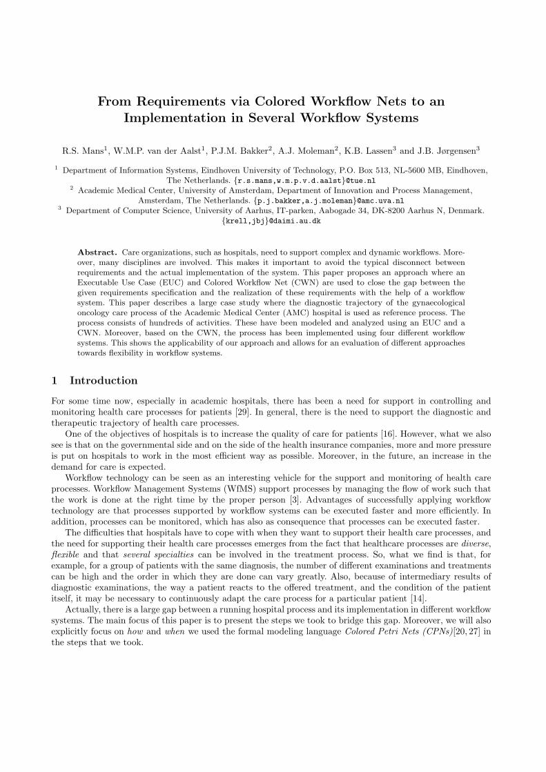
Fig. 1. Overall approach
The steps that we took for bridging the gap between a running hospital process and its implementation indifferent workflow systems are given in Figure 1. First of all, the healthcare process under consideration is thediagnostic trajectory of patients visiting the gynaecological oncology outpatient clinic in the AMC hospital,a large academic hospital in the Netherlands. This process covers what can happen from the moment that apatient is referred to the AMC hospital for treatment till the patient is eventually diagnosed or dismissed. Ascan be seen in Figure 1, we first had interviews with people involved in the healthcare process and made a CPNmodel out of it. This involved creating an Executable Use Case (EUC) [23], which is a CPN model augmentedwith a graphical animation. EUCs are formal and executable representations of work processes to be supportedby a new IT system and can be used in a prototyping fashion to specify, validate, and elicit requirements. Wewill present the EUC that has been created and elaborate on how it has been used. Afterwards, we convertedthe EUC into a Colored Workflow Net (CWN), which is closer to an implementation of the healthcare processin a workflow system. Finally, the CWN serves as a basis for implementation of the healthcare process in fourdifferent workflow systems. Also, as the CWN is a formal model of the workflow to be executed and servesas input for implementation of the process in different workflow systems we will, in Section 5, focus on theanalysis of the CWN to ensure that a correct CWN had been made.
Moreover, an additional goal of implementing a hospital process in different workflow systems is that wewanted to identify the requirements that have to be fulfilled by workflow systems, in order to be successfullyapplied in an hospital environment. To this end, we choose to implement the healthcare process in workflowsystems which already provide a certain kind of flexibility. As a consequence, as workflow management systems,we choose YAWL [4], FLOWer [11], ADEPT1 [37] and Declare [34]. However, in this paper we will not elaborateon the requirements identified.
The approach described above is closely related to the approach described in [7, 24]. In [7, 24], EUCs and aCWN have been used to go from an informal description of a real world process to an implementation of thesame process in a certain workflow system. However, we studied an existing healthcare process of a hospital indetail, whereas in [7, 24] rather small cases are used. To give an idea about the size of the healthcare process,it needs to be indicated that the EUC consists of 689 transitions, 601 places and 1648 arcs and that the CWNconsists of 324 transitions, 522 places and 1221 arcs. Moreover, we made an implementation in four differentworkflow systems instead of only one workflow system and systematically collected feedback from the careorganization (AMC). Furthermore, in [7] there was only user involvement in the EUC phase, whereas in [24]there has not been any user involvement.
2
This paper is structured as follows: Section 2 introduces the approach followed. Section 3 introduces theEUC and the gynaecological oncology healthcare process of the AMC hospital that we studied. In Section4, Colored Workflow Nets are introduced and used to model the selected process. This is followed by theimplementation of the healthcare process in four different workflow systems, in Section 6. In Section 5, we willfocus on the analysis of the CWN. Related work is given in Section 7. The paper finishes with the conclusionsin Section 8.
2 Approach
In this section, we will first elaborate in general on the approach that has been followed, to go from a real-life process to the implementation of this in several workflow systems. Afterwards, the separate steps will beconsidered in more detail. The steps followed in the approach were already shown in Figure 1. So, we startedwith a real-life case, and for which we created a EUC, a CPN model augmented with a graphical animation.Afterwards, the EUC is converted into a CWN, which is also a CPN model. The CWN is then used as basis forthe implementation of the healthcare process in four different workflow systems; namely YAWL [4], FLOWer[11], ADEPT1 [37], Declare [34].
We will now elaborate in more detail on the steps that have been followed, especially on the second and thirdstep that has been followed. As can be seen in Figure 1, the model used in the second and third step are CPNmodels. CPNs have been chosen because they provide a well-established and well-proven language suitable fordescribing the behavior of systems with characteristics like concurrency, resource sharing, and synchronization.In this way, they are well-suited for modeling workflows or work processes [3]. The CPN language itself, issupported by CPN Tools [13]. CPN Tools has been used to create, simulate, and analyze the CPN models thatare presented in this paper.
As can be seen in Figure 1, our approach started with interviewing users. The users were involved in thediagnostic trajectory of the gynaecological oncology healthcare process of the AMC hospital in Amsterdam. Inthese interviews we focussed on identifying the work processes which could then be modeled as a EUC. TheEUC consists of a CPN model, which describes the real-life process, and an animation layer on top of it, whichcan be shown to the users of which we modeled the process.
In the CPN model, any concepts and entities deemed relevant can be used. So, we can use the CPN languagein an unrestricted manner which means that tokens, places and transitions may refer to any concept or entity,i.e. also concepts which are not directly part of the process but still relevant from the users point of view.
Remember that, according to the definition given in [23], that EUCs are formal and executable represen-tations of work processes to be supported by a new IT system and can be used in a prototyping fashion tospecify, validate, and elicit requirements. Actually, we have used the model part of the EUC for modeling thehealthcare process and have used the animation layer as a vehicle for validating the model. In other words, weused EUCs for checking together with the users involved, whether we modeled their work processes correctly,instead of specifying, validating and eliciting requirements. Only the animations have been shown to the userwhereby the CPN model, which is lying beneath the animation layer, remains hidden for the user. This has beenthe main reason for using EUCs. As we were modeling the work processes of doctors and nurses, we assumedthat they were not able to understand the CPN model themselves. Therefore, we used animations which areunderstandable for end users and in this way provided a suitable opportunity for validating our model.
Furthermore, EUCs have to ability to “talk back to the user”, which is not possible with a static CPN model.As EUCs provide executable descriptions of a work process, they can be used in a trial-and-error fashion. Whenusers remark that something is wrong or missing, the EUC can easily be adapted and again shown to the user.
After we validated our model, we took the underlying CPN model of the EUC and translated it intoa workflow model. By making this workflow model we restricted ourselves to the workflow domain. Morespecifically, by making the workflow model, we restricted ourselves to concepts and entities which are commonin workflow languages. Compared to the EUC model, we now only used a fixed library of concepts and entities,whereas in the EUC any concept or entity deemed relevant may be used. In addition, the workflow model
3
contains actions that will be supported by the new system in interaction with human users, and it also containsactions that are to be fully automated by the new system. Actions that are not going to be supported by thenew system, are left out.
More specifically, as workflow model we used a, so called, Colored Workflow Net (CWN) as modelinglanguage. A CWN is a CPN model restricted to the workflow domain and can be seen as a high-level versionof the traditional Workflow Nets (WF-nets) [1].
When the CWN model had been finished, we used it as a basis for the process models used to configure eachof the four workflow systems. This way we implemented four systems to support the gynaecological oncologyhealthcare process. As workflow systems, YAWL, FLOWer, ADEPT1 and Declare have been chosen. All thesefour workflow systems provide a certain kind of flexibility, which in this context is deemed relevant. The reasonfor this is that we want to support a healthcare process and for supporting healthcare processes it is obviousthat a certain kind of flexibility is needed, and which needs to be provided by a workflow system. In Section6, we will elaborate more on these systems and discuss which kind of flexibility is exactly provided by eachsystem.
As is indicated in Figure 1, during the construction of the EUC and the CWN and the implementation inthe different workflow systems, additional insights can be obtained about previous phases. So, there can beoften iterations back and forth between the components in the figure. However, we only had feedback fromthe people involved in the process during the interview, EUC and CWN phase. In other words, during andafter finishing the implementation in the four workflow systems, we did not have any feedback from the peopleinvolved in the process. Although this could have given us valuable feedback about the process, we think wealready clearly identified the process during the construction of the EUC and CWN.
In Figure 1, we see that there exists a dashed line between the first two blocks and the last two blocks.This dashed line represents a shift of focus when going from the left side of the line to the right side of theline. At the left side of the dashed line the focus is on the context, whereas at the right side the focus is on therealization. So, with context we mean that the focus is on processes, resources, data, systems and decisions andwith realization we mean that the focus is on the system and software itself. Within this shift of focus, the CPNmodeling language, which has been used for the EUC and the workflow model, provides a smooth transitionbetween the two foci. In addition, we believe this addresses the classical “disconnect” which exists beweenbusiness processes and IT. Furthermore, as on the left side of the dashed line one of the foci on processes,this means that the approach via an EUC and CWN only works in case we are dealing with process orientedsystems, like document handling systems. This can also be derived from the fact that both the EUC and CWNare process models.
It is important to mention that all the models and translations between models have been done manually.In the end, this leads to a full implementation of a complete healthcare process in four different workflowsystems. Because of the specific nature of the EUC model and the CWN, it is obvious that the CWN cannot begenerated automatically from the EUC. This is because a decision needs to be made between what needs to besupported by the workflow system and what not, and which needs to be reflected within the CWN. However, inprinciple, a (semi-) automatic translation from the CWN to each of the workflow systems is possible. In [7, 24],it has been demonstrated that it is possible to (semi-) automatically generate BPEL code or a YAWL modelfrom a CWN model.
We already indicated that we studied a large healthcare process; the EUC consists of 689 transitions andthe CWN consists of 324 transitions. Moreover, for creating the EUC and the CWN more than 100 man hourswere needed for each model. As we also needed to get acquainted with the workflow systems used, configuringeach workflow system also took more than 80 man hours per system. Additionally, around 60 man hours wereneeded for interviewing and getting feedback from the people involved in the process.
3 Executable Use Case for the Gynaecological Oncology Healthcare Process
In this section, we first introduce the gynaecological oncology healthcare process which we studied. After that,we will consider one part of the healthcare process in more detail and for this part we will elaborate on how the
4
animations have been set-up within the EUC. In other words, for the selected part of the model, we elaborateon what is shown in the EUC and explain how still the routing within the model can be influenced. Finally,we will elaborate on the obtained experiences. Note that given the size of the CPN model of the EUC (689transitions, 601 places, 1648 arcs and 2 colorsets) it is only possible to show a small fragment of the overallmodel.
() ()
p
p
p
p
pp
p
p
p
p
p
p
p
p
p
p
p
pp
p
p
start Prepare pathology and radiology meeting
prepare pathology and radiology meeting
endsystem
startsystem
input ();output ();action(let val _ = setupAnimation()in () end);
consultation via
telephone
consultation via telephone
MDOmeeting
MDO meeting
visitoutpatient
clinic
visit outpatient clinic
Examinationunder
anesthethicsexamination under anesthethics
X ray
X ray
CT
CT
MRI
MRI
radiology meeting
radiology meeting
pathologymeeting
pathology meeting
pre-assessment
pre- assessment
firstvisit
first visit
pathology
pathology
referral patientand preparations
for first visit
referral patient and preparations for first visit
lab
lab
MDO
UNIT
startmeetings
UNIT
UNIT
end radiologymeeting
UNITrastart ra
UNIT
pastart pa
UNIT
gyn oncstart ra
UNIT
gyn oncstart pa
UNIT
prepare
UNIT
START
1`1
PATIENT
MRIneeded
PATIENT
subsequentvisits
PATIENT
pathologyneeded
PATIENT
END
PATIENT
euaneeded
PATIENT
CTneeded
PATIENT
pre-assneeded
PATIENT
labneeded
PATIENT
x ray needed
PATIENT
start firstvisit
PATIENT
startgyn onc
PATIENTreferral patient and preparations for first visit
pathology
radiology meeting
X ray
consultation via telephone visit outpatient clinic
end pathologymeeting
first visit
lab
MDO meeting
pathology meeting
prepare pathology and radiology meeting
pre- assessment examination under anesthethics
CT
MRI
Fig. 2. General overview of the gynaecological oncology healthcare process.
In Figure 2, the topmost page of the CPN model of the EUC is shown, which gives a general overview of thediagnostic trajectory of the gynaecologic oncology healthcare process in the AMC hospital. In the remainder ofthis paper, we will simply refer to the gynaecological oncology healthcare process itself, instead of the diagnostictrajectory of the gynaecological oncology healthcare process.
Actually, as can be seen in Figure 2, two different processes have been modeled which are relevant forthe gynaecological oncology healthcare process. The first process, which is modeled in the lower part of thepicture, deals with the diagnostic trajectory that is followed by a patient when referred to the AMC hospitalfor treatment, till the patient is diagnosed. In the first part of the process we have that already some diagnosticexaminations can be ordered, before actually the patient visits the hospital for the first time, like a MRI or aCT-scan. Moreover, also some administrative activities are already done before the patient visits the hospitalfor the first time. Later on, in this section, we will elaborate on more detail on this specific part of the process.
During the first visit of the patient to the hospital, the doctor examines the patient and decides whetherhe/she is confident with the already ordered examinations or that some new examinations need to be ordered.
5
In addition, the doctor decides about the next appointment(s) he want to have with a patient. Afterwards, thenurse is responsible for the arrangement of the dates of the additional examinations and the next appointment(s)with the doctor which can be either again a visit to the outpatient clinic or an appointment by telephone. Theseappointments are made together with the patient. Furthermore, also some administrative activities are done,like giving additional information about the treatment and handing over some folders.
As already indicated, the next appointment of the doctor with the patient can be either via telephone,or again a visit to the outpatient clinic. In general, at these appointments, the doctor decides about whichexaminations need to be ordered, canceled or replaced. The same holds for appointments of the doctor with apatient. In addition, some administrative activities need to be done, mostly by the nurse.
Actually, the doctor can order a lot of different examinations, and also at different specialties. For example,at the radiology department he can order an X-ray or a CT-scan or at the anaesthesiology department he canorder a pre-assessment. The interactions with these specialties and also the process within these specialties aremodeled at the bottom of Figure 2.
The second part of the process, which is modeled in the upper part of the picture in Figure 2, deals with theweekly organized meetings, on Monday afternoon, for discussing the status of patients and what needs to bedone in the future for these patients. These three different meetings are called “radiology meeting”, “pathologymeeting” and “MDO” and respectively people from radiology, pathology and people involved in the therapeutictrajectory are involved, as well as doctors from the gynaecological oncology itself.
Remark that some connections exist between the two processes. However, as we only focussed on theactivities and ordering of activities within one process, we did not put any effort in making these connectionsexplicit.
Now, after introducing the gynaecological oncology process in general, we want to focus on a specific partof the process. More specifically, we focus on the very beginning of the process (transition “referral patientand preparation for first visit”), in which a doctor of a referring hospital calls a nurse or doctor of the AMCand after which an appointment is made for the first visit of the patient and some appointments for diagnosticexaminations are already made. The appointment making part of the process is shown in the upper part ofFigure 3. For example, we see that the first visit of the patient needs to be planned and that it is possible tomake appointments for an “MRI”, “CT” or “pre-assessment”.
In Figure 3, we see how the CPN model and the animation layer are related within the EUC. At the top,we see the CPN model that is executed in CPN Tools. At the bottom we see the animation that is providedwithin the BRITNeY tool [12], the animation facility of CPN Tools. The CPN model and the animation layerare connected by adding animation drawing primitives to transitions in the CPN model, which update theanimation. The animation layer shows for the last executed activity in the CPN model, which resources, dataand systems are involved in executing the activities and it also shows which decisions are made at the activity.This allows for focusing on what happens in the context of the process. In addition, for the last executed activityin the model, a separate panel is shown which indicates which activities are enabled and may be executed.One of the enabled activities in the panel can be selected and executed, which changes the state of the processand in this way, we can directly influence the routing within a process. Remark, that in BRITNeY alreadyfunctionality is available for showing a panel with enabled bindings, but we slightly adapted it to our needs, sothat only the enabled activities are shown instead.
In this way, the animation layer provides a view on the current state of the process and shows which nextactivities may be executed. When an activity is executed in the CPN model it is reflected by updates to theanimation layer. Consequently, the CPN model and the animation layer remain synchronized.
In the snapshot shown in Figure 3, the animation visualizes activity “make document and stickers”. Inaddition, the panel at the top right side of the snapshot in Figure 3, shows which activities can be executedafter that activity “make document and stickers” has been executed. Moreover, in the animation we see that anurse of the outpatient clinic is responsible for executing the “make document and stickers” activity and thatno decisions need to be made. We also see that a computer is needed for executing the activity. Moreover, thepanel at the top right side shows that, amongst others, the activities “plan MRI” and “send fax to pathology”may be executed now.
6
Fig. 3. Animation belonging to the “make document and stickers” activity. In addition, the panel at the top right sideshows which activities are enabled now.
We have shown the animations to the people that were involved in the gynaecological oncology process.Before starting with the animations, we explicitly asked the people whether they wanted to indicate whethersomething was wrong, missing, or superfluous, with regard to the animation shown, and the enabled activitiesshown in the panel. In general, the people where very positive and indicated that in this way, they were ableto check whether the process modeled in the EUC corresponded with their workprocess. Also, they gave usefulfeedback about activities that had not been modeled or were placed in the wrong order, and whether theinformation which was shown for each activity, was correct or not. However, it needs to be indicated that later
7
on, when making the CWN model, we found out that some activities where missing and which we did notdiscover with the EUC approach. But in general, we can say that the EUC approach was really helpful invalidating the model and we believe that better results have been obtained than when we would have shownthe plain CPN models or process schemas of a workflow management system to the people involved.
4 Colored Workflow Net for the Gynaecological Oncology Healthcare Process
In this section, we first introduce the Colored Workflow Net (CWN) that has been made for the gynaecologicaloncology healthcare process and shortly discuss the differences between EUCs and CWNs. After that, we willconsider the same part of the CWN in detail as we considered in detail for the EUC. For the selected part of theCWN, we elaborate on what is shown regarding the different perspectives of the CWN. Finally, the differenceswith the corresponding part of the EUC are discussed. Note that also in this case, given the size of the CWNmodel (324 transitions, 522 places and 1221 arcs and 53 colorsets) it is only possible to show a small fragmentof the overall model.
As can be seen in Figure 1, both the EUC and CWN are CPN models. Remember that a CWN is a workflowmodel in which we restricted ourselves to concepts and entities which are common in workflow languages,whereas in the EUC any concept or entity deemed relevant may be used. Furthermore, as can be seen in Figure1, the focus of the CWN is on the realization, which means that the CWN only contains activities which willby be supported by the workflow system. Moreover, as workflow systems also cover the resource and dataperspective, it is clear that in addition to the EUC, which only covers the control-flow perspective, the CWNshould also cover the resource, data and operation 4 perspective. Moreover, the resource, data and operationperspective are covered by the CWN by using ML-functions, where the animation in the EUC only textuallyshowed resources, data, and systems.
The syntactical and semantical requirements for a CWN have been defined in [7]. Moreover, a CWN abstractsfrom implementation details and language/application specific issues. According to [7], a CWN should be aCPN with only places of type Case, Resource or CxR. Tokens in a place of type Case refer only to a case andthe corresponding attributes (e.g. name patient, patient id), and tokens in a place of type Resource refer onlyto resources. Finally, tokens in a place of type CxR refer to both a case and a resource. There are some subtledifferences between the conventions in [7] and the conventions we have used to construct the CWN, and ofwhich we mention only the two most important ones. First of all, the data attributes of the original CWNsin [7] may only be name-value pairs of the string type. In this way, we consider its use as quite limited as inpractice also often lists are used, and therefore we decided to also allow list types for the value part of thename-value pair. For example, patients which need to be discussed during the weekly pathology meeting areput on a, so called “pathology list”. To this end, in the CWN model, we need to have a data attribute withname “pathology list” and where the value part is of a list type. Furthermore, we decided to separate the casedata from the case, so that case data can be accessed everywhere in the model. For this we use the concept ofa fusion place in CPN Tools.
In Figure 4, we see the CWN for the EUC CPN which has been shown in Figure 3. In Figure 4, thereexist some connections between transitions and places of the type Resource and CaseData. In addition, by usingguards, which belong to a transition, explicit references are made to the resource and data perspective. Placesof the type Resource contain information about the availability of different kinds of resources and places of thetype CaseData contain information about the case data belonging to a case and is a product of a case identifierand the data belonging to that case. Note that tokens in places of type CaseID contain unique identifiers foreach case and that tokens in places of type CaseData are a product of a case identifier and case data. In thisway, activities can inspect or change case data for a certain case. Furthermore, tokens in a place of type CidxRrefer to both a case id and a resource.
For example, in Figure 4, we see that the activity “enter patient data into system” need to be performed bya nurse, and which is indicated by the guard at the top right side of the activity. Furthermore, activity “send4 The operation perspective describes the elementary operations performed by resources and applications.
8
Fig. 4. CWN for the EUC shown in Figure 3.
fax to pathology” may only be performed if the pathology slides of the referring hospital need to be sent tothe AMC, and which is specified by the guard with the texts “slides” and “needed” in it. From this guard, italso becomes clear that we need to have a data attribute with name slides, but in the model we may also haveother data attributes like name, patient id, or pathology list.
If we compare the CWN of Figure 4 with the EUC CPN of Figure 3, we see that there exist some differences.First of all, some activities which are shown in the EUC CPN do not appear in the CWN, as they are notsupported by the workflow system. The activities of the CWN in Figure 4 which can be directly mapped toactivities of the EUC in Figure 3 are colored green. In other words, they are preserved. For example, we seethat activities “enter patient data into system” and “plan MRI” are both in the EUC and CWN, so they arepreserved. The activities of the EUC which are not supported by the workflow system, and as a consequence donot pop up in the CWN, are colored purple. For example, the activities “send signal to nurse” and “communicatediagnosis to nurse” of Figure 3 are not supported by the workflow system.
Moreover, the places “Resources1” and “Resources2”, which are colored red, are only present in the CWN asit contains information about the availability of resources and which is needed for the organizational perspectiveof the CWN. Also, the place “Case global”, which is colored blue, is only present in the CWN as it contains
9
the corresponding data attributes for each case instance and which is needed for the data perspective of theCWN. Furthermore, the guards belonging to transitions explicitly reference the resource and data perspective.
When we compare the EUC and CWN with each other it is clear that both cover the control flow perspective.However, the CWN also covers the resource, data and operation perspective. As these perspectives are alsocovered by workflow systems it is clear that the CWN, when compared to the EUC, is the next and also usefulstep towards the implementation of a process in a certain workflow system.
5 Analysis
In this section, we will focus on the analysis of the CWN model. Within CPN Tools there are two possibilitiesfor the analysis of the CWN model, namely; simulation / animation and state space analysis [21]. Simulationcan be used to investigate different scenarios and explore the behaviors of the model. Moreover, simulation alsoallows for performance analysis. However, performing several simulations does not guarantee that there are noerrors within the model and in this way does not hold as a proof for correctness of the model. Therefore, statespace analysis needs to be used for verification as it ensures that all possible executions are covered. In otherwords, with a state space analysis, the full state space of a CPN model is computed which makes it possible toverify, in the mathematical sense of the word, that the model possesses a certain formally specified property.The state space analysis of CPN Tools can handle state spaces up to 200.000 nodes and 2.000.000 arcs [22] andprovides, amongst others, visual inspection and query functions for investigating (behavioral) properties of themodel.
Since we are dealing with workflows we are interested in the so-called soundness property. Soundness forworkflow nets is defined in [1] as: for any case, the procedure will terminate eventually and the moment theprocedure terminates there is a token in the sink place (i.e. a place with no outgoing arcs) and all the otherplaces are empty. Moreover, there should be no dead transitions. To check for soundness of the CWN, we needto abstract from resources. Moreover, as the CWN is exceptionally large (324 transitions, 522 places and 1221arcs and 53 colorsets) we also need to simplify the colorsets and verify things in a hierarchical manner. To bemore precise, for each transition on the top page of the CWN which was linked to a subnet, we checked thesoundness of the subnet. Note that such a subnet can also contain subnets. Checking the soundness of sucha subnet has been done according to the following procedure. First, we only focussed on the subnet itself byremoving all nodes and subnets from the cpn file which did not belong to the subnet being considered. In otherwords, only the subnet being considered was kept in the CPN file. Second, we removed all colorsets and all dataattributes which were not relevant for the subnet being considered. A data attribute was not considered relevantwhen there was not any function in the subnet which actually accessed the data attribute. After finishing thetwo preceding pre-processing steps, we were actually ready to check whether the subnet was sound. For theactual check for soundness we added an extra transition t∗ in the subnet which connects the only output placewith the only input place and is also called short-circuited net [1]. According to [1], if the short-circuited netis live and bounded, then the original net is sound. If some error had been found, the subnet was adapted andagain checked for its soundness. This last step has been repeated till the subnet was sound. Afterwards, if someerrors had been found, the CWN model had been adapted in the same way. A limitation of the approach isthat a subnet which is checked for its soundness should not be too large and / or have many colorsets.
For example, for the CWN, shown in Figure 4, we originally found out that for the activities “skip plan MRI”and “skip plan CT” no double-headed arc had been used between these transition and place “CaseGlobal”.This could be concluded from the liveness properties of the state space report of the short-circuited net whichare shown in Figure 5. In Figure 5, it can be seen that there are no live transition instances whereas for theshort-circuited net all transitions had to be live and all places had to be bounded in order for the original netto be sound. From one of the dead markings the errors could be located and easily be fixed. So, For the CWNshown in Figure 4 all transitions are live and all places are bounded for the short-circuited net which meansthat it is sound. Moreover, for this sound CWN, it took 1901 seconds to calculate the full state space whichconsists of 39808 nodes and 156800 arcs.
10
Fig. 5. Liveness Properties section of the state space report generated for the erroneous CWN.
In general, for each subnet we found around one or two errors, but we also had subnets which were error-free. Furthermore, although there are more interesting structural properties which can be checked for, we onlychecked for soundness.
6 Realization of the system in different workflow systems
In this section, we will focus on the realization of the system in four different workflow systems. As workflowsystems, the systems YAWL, FLOWer, ADEPT1 and Declare have been chosen. All these workflow systemsprovide a certain kind of flexibility, which in the context of implementing a healthcare process in differentworkflow systems, is deemed relevant. It is clear that for supporting healthcare processes some flexibility needsto be provided by the workflow system. Moreover, these workflow systems have been chosen as we wanted toidentify the requirements that have to be fulfilled by workflow systems, in order to be successfully applied in anhospital environment. However, in this paper we will not elaborate on the requirements identified. Furthermore,we could easily obtain each of these systems.
For each of the four workflow systems that provide flexibility, we will discuss the kind of flexibility which isprovided.
As input for the implementation, the CWN will be used. For each system, we will exemplify how the CWNmodel is mapped to the modeling language used in the workflow system itself. This is done by manually mappingthe CWN of Figure 4 to the modeling language used in the workflow system itself. Differences are comparedand, in this way, also an impression of the workflow system itself is obtained.
At the end of this section we will elaborate on the applicability of a CWN for implementation of a processin a workflow system.
6.1 YAWL / Worklets
YAWL (Yet Another Workflow Language) [4] is an open source workflow management system5, which is basedon the well-known workflow patterns6 [5] and is more expressive than any of the other languages available today.Moreover, instead of only supporting the control-flow perspective and data perspective, YAWL also supportsthe resource perspective.
YAWL supports the modeling, analysis and enactment of flexible processes by, so called, worklets [9] andwhich can be seen as a kind of process fragments. Specific activities in a process are linked to a repertoire ofpossible actions. Based on the properties of the case and other context information, the right action is chosen.The selection process is based on a set of rules. Also, during enactment it is possible to add new actions to therepertoire.5 YAWL can freely be downloaded from www.yawl-system.com6 More information about the workflow patterns can be found on www.workflowpatterns.com
11
Fig. 6. Screenshot of the YAWL editor.
In Figure 6, we see how the CWN of Figure 4 is mapped onto the YAWL language. Given the fact thatYAWL can be seen as a superset of CWNs, it was easy to translate the CWN of Figure 4 in YAWL. So, itwas possible to directly translate the transitions into YAWL tasks. The places of the CWN model can also bedirectly translated into YAWL conditions, but due to syntactical sugaring there is no need to add all placesas conditions to the YAWL model. For example, the “make document and stickers” activity in YAWL is anOR-split, which has as meaning that one or more of the outgoing paths may be followed, which means that itis optionally to follow the paths to, for example, the “plan MRI” and “plan CT” activities. In this way, theskip activities which appear in the CWN are not needed in the YAWL model.
Finally, the YAWL model consists of 231 nodes and 282 arcs and for which it took around 120 hours toconstruct a model that could be executed by the YAWL workflow engine.
6.2 FLOWer
FLOWer is a commercial workflow management system provided by Pallas Athena, the Netherlands7. FLOWeris a case-handling product [8]. Case-handling adds flexibility by focussing on the data aspect rather than on thecontrol-flow aspect. Case-handling offers four core features [8]. The first one is that all information availablewithin a case is available (i.e., present the case as a whole rather than showing just bits and pieces), which avoids“context tunneling”. Second, the decision of which activities are enabled is based on the information whichis available within the case, instead of the activities which are already executed. Third, work distribution isseparated from authorization. This allows for having additional types of roles, like skipping or redoing activitiesin the process. In this way, many more (implicit) scenarios are possible within the process. Moreover, a fourthdistinguishing feature of Flower is that workers are allowed to view and add/modify data before or after thecorresponding activities have been executed.
In Figure 7, we see how the CWN of Figure 4 is mapped onto the FLOWer language. In this case, it wasalso quite easy to translate the CWN in FLOWer. Namely, it was possible to directly translate the transitions
7 http://www.pallas-athena.com/
12
Fig. 7. Screenshot of the FLOWer editor.
into FLOWer activities and also the causal relationships could be taken into account. In Figure 7, all nodes areactivities except the node with name “choice tel contact”. This node represents the deferred choice which needsto be made in the beginning of the process, as can be seen in Figure 4. So, in the beginning of the process,either the “ask information from doctor referring hospital” activity can be chosen or the “write down datapatient and make decision” activity can be chosen, but not both.
Finally, the FLOWer model consists of 236 nodes and 190 arcs and for which it took around 100 hours toconstruct a model that could be executed by the FLOWer workflow engine.
6.3 ADEPT1
ADEPT1 is an academic prototype workflow system [37], developed at University of Ulm, Germany. ADEPT1supports dynamic change which means that the process of one individual case can be adapted. So, it is allowedto deviate from the pre-modeled process template (skipping of steps, going back to previous steps, insertingnew steps, etc.) in a secure and safe way. That is, the system guarantees that all consistency constraints (e.g.,no cycles, no missing input data when a task program will be invoked) which have been ensured prior to thedynamic (ad hoc) modification of the process instance are also ensured after the modification.
In Figure 8, we see how the first part of the CWN of Figure 4 is mapped onto the ADEPT language. In theADEPT language, the activities are represented by rectangles. However, as in the ADEPT language we onlyhave an XOR and an AND split and join, we need to introduce activities which are empty, i.e they are notexecuted by users. For example, the “make stickers and document” activity in ADEPT is an AND-split whichis followed by several empty XOR-splits in order that several activities, like “plan MRI” or “plan CT” can beperformed or skipped.
13
Fig. 8. Screenshot of the ADEPT1 editor. AND-splits/joins are represented by a black rectangle in a node and XOR-splits/joins are represented by a black triangle in a node.
Finally, the ADEPT model consists of 40 nodes and 53 arcs and for which it took around 8 hours to constructa model that could be executed by the ADEPT1 workflow engine.
6.4 Declare
Declare is an academic prototype workflow system [34], developed at Eindhoven University of Technology, theNetherlands8. In Declare the language used for specifying processes, which is called ConDec, is a declarativeprocess modeling language, which means that it is specified what should be done. Imperative process modelinglanguages, like YAWL and FLOWer, specify how it should be done, which leads to over-specified processes. Byusing a declarative rather than an imperative / procedural approach, ConDec aims at an under-specificationof the process where workers have room to “maneuver”.
The ConDec language allows for modeling and enacting dynamic processes and is based on Linear TemporalLogic (LTL) [25]. In this way, it can be specified which behavior is forbidden. Moreover, within Declare it is veryimportant to mention that it is assumed that users already know what should be done. The users can executeactivities in any order and as often as they want, but they are bound to certain rules, which are specified inthe ConDec language.
Furthermore, Declare also supports dynamic change, so that the process of individual cases can be adapted.In terms of Declare, this means that it is allowed to deviate from the pre-modeled process template by addingor removing activities or constraints. Also, model correctness is guaranteed, which means that it is checked byDeclare whether the changes are allowed or not for the cases for which the changes are intended to be applied.
In Figure 9, we see how the CWN of Figure 4 is mapped onto the ConDec language. In the ConDec language,the activities are represented by rectangles. Moreover, each different LTL formula, which can be used in themodel, is represented by a different template, and can be applied to one or more activities, dependent on thearity of the LTL formula which is used. Note that the language is extendible, i.e., it is easy to add a newconstruct by selecting its graphical representation and specifying its semantics in terms of LTL.
The activities of the CWN model could easily be translated to activities in the ConDec language. However,as the ConDec language is a declarative process modeling language, and not an imperative language, the causalrelationships of the CWN model could not easily be translated to the ConDec model. Moreover, we also had8 http://is.tm.tue.nl/staff/mpesic/declare.htm
14
Fig. 9. Screenshot of the Declare editor.
to take into account that within Declare it is assumed that users already know what should be done. To thisend, we made the ConDec model, in such a way, that we ruled out forbidden behavior and that the users knowas early as possible what should be done, and from that moment on, the user itself is responsible for decidingwhich activities should be done and in which order.
In Figure 9, we see that after activity “enter patient data into system” a lot of subsequent activities needto be done, and which is indicated by a response arc going from the “enter patient data into system” activityto these activities, like “plan ct” and “plan mri”. However, it is only modeled that these activities need to bedone afterwards, but not in which order. Also, during runtime, it is indicated to the user which activities needto done and then the user himself can decide in which order he wants to execute the activities and how often.Moreover, with ConDec it is also easy to model that the execution of one activity rules out the execution ofanother activity, and the other way around. For example, the “not-coexistence” arc between activities “planmri” and “plan ct” specifies that only one of these activities may be executed, but not both.
For Declare we did not implement the full healthcare process as in Declare there is only support for scalardata types, like integer and boolean, but not for more advanced data types like lists, etc. We only implementedthe process which is depicted in Figure 4 and which consists of only 10 percent of the whole CWN model.Nevertheless, the model that we made in Declare still consists of 23 nodes and 44 LTL formulae and for whichit took around 12 hours to construct a model that could be executed by the Declare workflow engine.
6.5 Applicability of CWNs for implementation of the system in different workflow systems
To conclude this section, we will elaborate on the applicability of CWNs for implementing the healthcareprocess into the four different workflow systems. In other words, we try to answer the question of how easy is
15
it to implement the CWN in a workflow system. We demonstrate how CWNs can be used as a starting pointfor implementation in a workflow system and evaluate the different systems. To this end, we use five differentcriteria, which are listed in the top row of table 1. The different workflow systems are given in the first column.
As first criterion, we have the number of nodes and arcs. For all the first tree workflow systems considered,the nodes in the CWN which referred to activities could directly be translated to activities into the workflowlanguage of the workflow systems and also only these nodes needed to be copied. However, for ADEPT1 wehad to use artificial nodes as only XOR and AND split and joins are possible.
As indicated in [7], a CWN covers the control flow, resource and data perspective. Furthermore, as forthe transitions in our CWN it is also required to manipulate the data attributes of a case, the CWN alsocovers the operation perspective[1]. For these last four criteria, we indicated how much effort in man hours ittook to specify each perspective in each workflow system. Please remember that for all systems, we createda model which could be executed by the systems workflow engine. However, within Declare and ADEPT1 weonly defined 10 percent of the model that we had within YAWL and FLOWer.
With regard to the second criterion, effort required for the control flow perspective, it was easy to translatethe control flow perspective of the CWN to the YAWL, FLOWer and ADEPT1 workflow language, as they areall imperative languages as is also the case for the CWN. As the ConDec language of Declare is an declarativeprocess modeling language and that in Declare it is also assumed that the users already know what shouldbe done, it is clear that the control flow perspective of the CWN could not directly be translated to theConDec language and which also took quite some effort. This can also be derived when we have a look at thenormalized man hour values for the second criterion. From these normalized values we see that it takes moretime to implement the control flow perspective in Declare compared to the other systems and also comparedto the total implementation time within Declare 9.
With regard to the third criterion, effort required for the organizational perspective, the resource relatedparts of the CWN could easily be translated. All workflow systems considered supported the possibility todefine roles which could be linked to activities.
The data perspective, the fourth criterion, could easily be translated to the workflow language of YAWL,FLOWer as these systems support directly or indirectly the same data types as defined in the CWN. As bothDeclare and ADEPT1 only support scalar data types, the data attributes of the CWN which uses lists could notbe covered by both languages. As it is more time consuming to define advanced data types compared to simplescalar types, this explains why in Declare and ADEPT1, when looking to the normalized values, relatively lesstime was needed for implementation of the data perspective compared to the other workflow systems.
With regard to the fifth criterion, effort required for the operation perspective, we see in the table thatthe operation perspective of the CWN was hardly useful for defining the operation perspective in the differentworkflow systems. The reason for this is, that each workflow language has its own specific way/language fordefining, for example, guards and how data attributes need to be manipulated. Furthermore, specifying theoperational perspective in the CWN itself was also quite difficult. Also, as in Declare and in ADEPT1 we onlyhad to deal with simple scalar types within the operation perspective, this explains why in Declare, when lookingto the normalized values, less time was needed for implementation of the operation perspective compared tothe other workflow systems.
To conclude, we can say that the CWN is of help for the implementation of a certain process in a workflowsystem. Furthermore, building a EUC and a CWN allows for a separation of concerns. More specifically, EUCsare good for capturing the requirements of a process, without thinking of how it is realized. CWNs, on itsturn, are good because the control-flow, resource, data and operation perspectives are defined. As an EUC hascaptured the requirements of a process it is a valuable input for a CWN. Using this development process, weare sure that these concerns are dealt with at the right time as we have to deal with them anyways. The onlydisadvantage is that the operational perspective of the CWN cannot be translated to the different workflowsystems. Furthermore, for Declare and ADEPT1 we used normalized values for the last four criteria. We think
9 As in ADEPT1 and Declare only 10 percent of the model has been defined, normalization for these systems is doneby multiplying the hour values by 10.
16
these normalized values are still representative, as for the implementation of the other 90 percent indeed a betterinsight into the system will be obtained, but on the other hand, parts of the process need to be implementedin another way than other parts. In this way, we assume that these two facts compensate each other.
Table 1. Translation of the CWN into the workflow languages of YAWL, FLOWer and Declare. Please remember thatwithin Declare and ADEPT1 we only defined 10 percent of the model that we had within YAWL and FLOWer.
Furthermore, in principle, a (semi-) automatic translation from the CWN to each of the workflow systemsis possible. More specifically, the control flow and resource perspective are subject to an automatic translation.With regard to the data perspective, also data attributes which are name-value pairs of the string type aresubject to automatic translation. However, for the operation perspective and for name-value pairs for whicha list type has been used, more carefulness is needed. For both of them, a semi-automatic translation will beneeded.
7 Related Work
From literature, it can be derived that workflow systems are not applicable for the healthcare domain [10, 28].The current generation of workflow systems adequately supports administrative and production workflows butthey are less adequate for healthcare processes which have more complex requirements [10]. In addition, in [35,36], it has been indicated that so called “careflow systems”, systems for supporting care processes in hospitals,have special demands with regard to workflow technology. One of these requirements is that flexibility needsto be provided by the workflow system [31, 40]. Unfortunately, current WfMS are falling short with regardto providing flexibility, which is also seen as an important problem in literature [6, 8, 9, 15, 26, 38]. Also, oncea workflow-based application has been configured on the basis of explicit process models, the execution ofrelated process instances tends to be rather inflexible [2, 37, 39, 43]. Consequently, the lack of flexibility hassignificantly limited the application of workflow technology. The workflow systems that we chose in this paper(YAWL, FLOWer, ADEPT1 and Declare) allow for more flexibility than classical workflow systems.
Moreover, with regard to the requirements for applying workflow technology in the healthcare domain, in[18] it is indicated that real time patient monitoring, detection of adverse events, and adaptive responses tobreakdown in normal processes is needed. As adaptive workflow systems are rarely implemented, this makescurrent workflow implementations inappropriate for healthcare [41]. Also, [14, 16, 32, 31, 40] stress that work-flow systems have to support dynamic adaptation of running workflows to handle the flexibility of healthcare(therapy) processes. In case of breakdowns, managing exceptions is unavoidable [17]. Furthermore, in a realclinical setting, it is a critical challenge for any workflow management system how capable it is to respondeffectively when exceptions occur [33].
Furthermore, what is lacking is that no support is provided for the multidisciplinary nature of health-care processes. In [42, 19, 30], the processes for only one department in a hospital are supported by a work-flow management system. So, a requirement is that support needs to be provided for the support of cross-departmental healthcare processes which is stressed in [29, 14, 40]. Finally, a completely different requirement
17
is that autonomous, independently developed applications needs to be integrated which is risky, costly andtime-consuming [28].
This paper uses the approach initially proposed in [7, 24] where also an EUC and CWN have been used togo from an informal inscription of a real world process to an implementation of the same process in a certainworkflow system. For [24], an electronic patient record system has been implemented in the YAWL system andis, in this way, related to the healthcare domain. However, for both papers, it holds that rather small caseshave been used and that only an implementation has been done in one workflow system. Furthermore, in [7]there was only user involvement in the EUC phase, whereas in [24] there has not been any user involvement.In our case, we modeled a much larger and real healthcare process of a hospital using four different workflowsystems. Moreover, the approach was evaluated by the people involved in the process.
The use of EUCs has also been inspired by the work done in [23], in which EUCs where used to prototypean electronic patient record system for hospitals in Aarhus, Denmark.
8 Conclusions
In this paper, we have focussed on the implementation of a large hospital process consisting of hundredsof activities, into different workflow systems. To ease the implementation process, we have first made anEUC, followed by a CWN. This CWN was used as input for configuring the different workflow systems. Theapproach followed has been described in Figure 1. As the approach to go from a EUC to a CWN and finallyan implementation in different workflow systems, nicely bridges the gap between the modeling of a real-worldprocess and the implementation of the process in a workflow system, three other important lessons have beenlearned.
The first lesson is that EUCs are a great help for validating the modeled real-world process used in thispaper. Instead of showing the model itself to the people involved in the process, which is very difficult tounderstand for these people, we have used the EUC for showing to the people involved how we modeled theirworkprocess. Within the EUC, we focussed on animating relevant information about the last executed activityto the user and we also focussed on showing the activities, which can be executed afterwards. In this way,the people involved could easily check whether the process modeled in the EUC corresponded to their actualworkprocess, which was also confirmed by the people themselves.
The second lesson learned is that the CWN helps on elaborating how the process considered, needs to bemade ready for implementation in a workflow system. As the CWN is a workflow model, we had to restrictourselves to concepts and entities that are common in workflow languages. So, activities that will not be sup-ported by the workflow system are left out in the CWN and also the resource, data and operational perspectiveneeds to be handled in a structured / uniform way.
Furthermore, it is clear that the CWN is also helpful for implementations of the process in a workflow system.The nodes of the CWN referring to activities can be directly translated and also the control flow, resource anddata perspective of the CWN can easily be translated to the workflow language of a workflow system. Thisdoes not hold for the operation perspective of the CWN and, together with the previous observations, formsthe third lesson learned.
Additionally, EUCs and CWNs are useful as they respectively capture the requirements of a process anddefine the control-flow, resource, data and operation perspective. With regard to man hours needed for ourapproach, interviewing and getting feedback from the people involved in the process took around 60 hours, andcreating the EUC and CWN took more than 100 man hours for each model. Finally, the configuration of theworkflow systems took around 240 hours.
A direction for future research is to develop animations specific for CWN. In this way, before a process willbe supported by a workflow system, the people can already become acquainted with how their process willbe supported by a workflow system and already start experimenting. Moreover, the case study also providedvaluable insights into the requirements for workflow technology in care organizations. Besides the need forflexibility, it revealed the need for a better integration of the patient flow with the planning of appointmentsand peripheral systems supporting small and loosely coupled workflows (e.g. lab tests).
18
Acknowledgements
We would like to thank Lisa Wells and Kurt Jensen for their support in using CPN Tools. Also, we would liketo thank Michael Westergaard for his support in using the BRITnEY tool. Furthermore, we also want to thankthe people of the gynaecological oncology, radiology, pathology and anesthetics department, and especiallyprof. Burger of the gynaecological oncology department for the time spent, on explaining the gynaecologicaloncology healthcare process.
References
1. W.M.P. van der Aalst. Business Process Management Demystified: A Tutorial on Models, Systems and Standardsfor Workflow Management. In J. Desel, W. Reisig, and G. Rozenberg, editors, Lectures on Concurrency and PetriNets, volume 3098 of Lecture Notes in Computer Science, pages 1–65. Springer-Verlag, Berlin, 2004.
2. W.M.P. van der Aalst, P. Barthelmess, C.A. Ellis, and J. Wainer. Workflow Modeling using Proclets. In O. Etzionand P. Scheuermann, editors, 7th International Conference on Cooperative Information Systems (CoopIS 2000),volume 1901 of Lecture Notes in Computer Science, pages 198–209. Springer-Verlag, Berlin, 2000.
3. W.M.P. van der Aalst and K.M. van Hee. Workflow Management: Models, Methods, and Systems. MIT press,Cambridge, MA, 2002.
4. W.M.P. van der Aalst and A.H.M. ter Hofstede. YAWL: Yet Another Workflow Language. Information Systems,30(4):245–275, 2005.
5. W.M.P. van der Aalst, A.H.M. ter Hofstede, B. Kiepuszewski, and A.P. Barros. Workflow Patterns. Distributed andParallel Databases, 14(1):5–51, 2003.
6. W.M.P. van der Aalst and S. Jablonski. Dealing with Workflow Change: Identification of Issues and Solutions.International Journal of Computer Systems, Science, and Engineering, 15(5):267–276, 2000.
7. W.M.P. van der Aalst, J.B. Jørgensen, and K.B. Lassen. Let’s Go All the Way: From Requirements via ColoredWorkflow Nets to a BPEL Implementation of a New Bank System Paper. In R. Meersman and Z. Tari et al., editors,On the Move to Meaningful Internet Systems 2005: CoopIS, DOA, and ODBASE: OTM Confederated InternationalConferences, CoopIS, DOA, and ODBASE 2005, volume 3760 of Lecture Notes in Computer Science, pages 22–39.Springer-Verlag, Berlin, 2005.
8. W.M.P. van der Aalst, M. Weske, and D. Grunbauer. Case Handling: A New Paradigm for Business Process Support.Data and Knowledge Engineering, 53(2):129–162, 2005.
9. M. Adams, A.H.M. ter Hofstede, D. Edmond, and W.M.P. van der Aalst. Facilitating Flexibility and DynamicException Handling in Workflows. In O. Belo, J. Eder, O. Pastor, and J. Falcao e Cunha, editors, Proceedings ofthe CAiSE’05 Forum, pages 45–50. FEUP, Porto, Portugal, 2005.
10. K. Anyanwu, A. Sheth, J. Cardoso, J. Miller, and K. Kochut. Healthcare Enterprise Process Development andIntegration. Journal of Research and Practice in Information Technology, 35(2):83–98, May 2003.
11. Pallas Athena. Case Handling with FLOWer: Beyond workflow. Pallas Athena BV, Apeldoorn, The Netherlands,2002.
12. CPN Group, University of Aarhus, Denmark. BRITNeY Suite Home Page.http://wiki.daimi.au.dk/britney/britney.wiki.
13. CPN Group, University of Aarhus, Denmark. CPN Tools Home Page. http://wiki.daimi.au.dk/cpntools/.14. P. Dadam, M. Reichert, and K. Kuhn. Clinical Workflows - The Killer Application for Process-oriented Information
Systems? In W. Abramowicz and M.E. Orlowska, editors, BIS2000 - Proc. of the 4th International Conference onBusiness Information Systems, pages 36–59, Poznan, Poland, April 2000. Springer-Verlag.
15. C.A. Ellis, K. Keddara, and G. Rozenberg. Dynamic change within workflow systems. In N. Comstock, C. El-lis, R. Kling, J. Mylopoulos, and S. Kaplan, editors, Proceedings of the Conference on Organizational ComputingSystems, pages 10 – 21, Milpitas, California, August 1995. ACM SIGOIS, ACM Press, New York.
16. U. Greiner, J. Ramsch, B. Heller, M. Loffler, R. Muller, and E. Rahm. Adaptive Guideline-based TreatmentWorkflows with AdaptFlow. In K. Kaiser, S. Miksch, and S.W. Tu, editors, Proceedings of the Symposium onComputerized Guidelines and Protocols (CGP 2004), Computer-based Support for Clinical Guidelines and Protocols,pages 113–117, Prague, 2004. IOS Press.
17. M. Han, T. Thiery, and X. Song. Managing Excpetions in the Medical Workflow Systems. In Proceeding of the 28thinternational conference on Software engineering , pages 741 – 750, Shanghai, China, 2006. ACM Press.
19
18. Y. Han, A. Sheth, and C. Bussler. A taxonomy of adaptive workflow management. 1998.19. T. Wendler J. von Berg, J. Schmidt. Business Process Integration for Distributed Applications in Radiology. In
Third International Symposium on Distributed Objects and Applications (DOA’01), pages 10–19, Rome, Italy, 2001.20. K. Jensen. Coloured Petri Nets. Basic Concepts, Analysis Methods and Practical Use. Volume 1. EATCS monographs
on Theoretical Computer Science. Springer-Verlag, Berlin, 1997.21. K. Jensen, L.M. Kristensen, and L. Wells. Coloured Petri Nets and CPN Tools for Modelling and Validation of
Concurrent Systems. International Journal on Software Tools for Technology Transfer, 9(3-4):213–254, 2007.22. K. Jenssen, S. Christensen, and L.M. Kristensen. CPN Tools State Space Manual. Department of Computer Science,
Univerisity of Aarhus, January 2006.23. J.B. Jørgensen and C. Bossen. Executable Use Cases: Requirements for a Pervasive Health Care System. IEEE
Software, 21(2):34–41, 2004.24. J.B. Jørgensen, K.B. Lassen, and W.M.P. van der Aalst. From Task Descriptions via Coloured Petri Nets Towards
an Implementation of a New Electronic Patient Record. In Proceedings of the Seventh Workshop on the PracticalUse of Coloured Petri Nets and CPN Tools (CPN 2006), volume 579, pages 17–36. University of Aarhus, 2006.
25. E.M. Clarke Jr., O. Grumberg, and D.A. Peled. Model Checking. The MIT Press, Cambridge, Massachusetts andLondon, UK, 1999.
26. M. Klein, C. Dellarocas, and A. Bernstein, editors. Adaptive Workflow Systems, Special Issue of Computer SupportedCooperative Work, 2000.
27. L.M. Kristensen, S. Christensen, and K. Jensen. The Practitioner’s Guide to Coloured Petri Nets. InternationalJournal on Software Tools for Technology Transfer, 2(2):98–132, 1998.
28. R. Lenz, T. Elstner, H. Siegele, and K. Kuhn. A Practical Approach to Process Support in Health InformationSystems. Journal of the American Medical Informatics Association, 9(6):571–585, December 2002.
29. R. Lenz and M. Reichert. IT Support for Healthcare Processes - Premises, Challenges, Perspectives. Data andKnowledge Engineering, 61:49–58, 2007.
30. T. Greiser R. Rohrig M. Meister M. Sedlmayr, T. Rose and A. Michel-Backofen. Automating Standard OperatingProcedures in Intensive Care. Accepted for CaiSE2007.
31. L. Maruster, W.M.P. van der Aalst, A.J.M.M. Weijters, A. van den Bosch, and W. Daelemans. Automated Discoveryof Workflow Models from Hospital Data. In C. Dousson, F. Hoppner, and R. Quiniou, editors, Proceedings of theECAI Workshop on Knowledge Discovery and Spatial Data, pages 32–36, 2002.
32. S. Miksch, R. Kosara, and A. Seyfang. Is Workflow Management Appropriate for Therapy Planning? In Proceedingsof EWGLP 2000, pages 53–69, Amsterdam, 2000. IOS Press.
33. S. Panzarasa and M. Stefanelli. Workflow management systems for guideline implementation. Neurological Sciences,27:245–249, June 2006.
34. M. Pesic and W.M.P. van der Aalst. A declarative approach for flexible business processes management. In J. Ederand S. Dustdar, editors, Business Process Management Workshops (Proceedings BPM 2006 International Workshops,volume 4103 of Lecture Notes in Computer Science, pages 169–180, Vienna, Austria, September4-7 2006. Springer.
35. S. Quaglini, M. Stefanelli, A. Cavallini, G. Micieli, C. Fassino, and C. Mossa. Guideline-based Careflow Systems.Artificial Intelligence in Medicine, 20(1):5–22, 2000.
36. S. Quaglini, M. Stefanelli, G. Lanzola, V. Caporusso, and S. Panzarasa. Flexible Guideline-based Patient CareflowSystems. Artificial Intelligence in Medicine, 22(1):65–80, 2001.
37. M. Reichert and P. Dadam. ADEPTflex - Supporting Dynamic Changes of Workflows Without Loosing Control.Journal of Intelligent Information Systems, 10(2):93–129, 1998.
38. S. Rinderle, M. Reichert, and P. Dadam. Correctness Criteria For Dynamic Changes in Workflow Systems: A Survey.Data and Knowledge Engineering, 50(1):9–34, 2004.
39. S. Sadiq, O. Marjanovic, and M.E. Orlowska. Managing Change and Time in Dynamic Workflow Processes. Inter-national Journal of Cooperative Information Systems, 9(1-2):93–116, 2000.
40. M. Stefanelli. Knowledge and Process Management in Health Care Organizations. Methods Inf Med, 43:525–535,2004.
41. J. Sutherland and W.-J. van den Heuvel. Towards an intelligent hospital environment: Adaptive workflow in the orof the future. 2006.
42. T. Wendler, K. Meetz, and J. Schmidt. Workflow Automation in Radiology. In H.U. Lemke, editor, Proceedings ofComputer Assisted Radiology and Surgery (CAR98), pages 364–369. Elsevier, 1998.
43. M. Weske. Formal Foundation and Conceptual Design of Dynamic Adaptations in a Workflow Management System.In R. Sprague, editor, Proceedings of the Thirty-Fourth Annual Hawaii International Conference on System Science(HICSS-34). IEEE Computer Society Press, Los Alamitos, California, 2001.