Every proton for the domestic United States High Energy Physics experimental program will be
accelerated by the existing, now 40-year-old, Fermilab Linac and Booster until new machines are
operational to replace them. Completion of the proposed Fermilab Project X accelerator is
anticipated no sooner than 2020 for beams up to 3 GeV and well into that decade for beams at
higher energy. The domestic High Energy Physics program for the next 15 years relies on the
viability and vitality of the Fermilab Linac and Booster.
The Proton Source Improvement Plan (PIP) is an effort to address the call by the Associate Director
for Accelerators for “delivering 1.8E17 (8 GeV) protons/hour (at 12 Hz) by May 1, 2013” and
“delivering 2.25E17 protons/hour (at 15 Hz) by January 1, 2016” while “ensuring a useful operating
life of the proton source through 2025.”
Plan elements are categorized into three major focus areas: Maintaining viable and reliable operation of the Linac and Booster through 2025;
Increasing the Booster RF pulse repetition rate;
Doubling the proton flux while maintaining 2010 residual activation levels; The PIP Design Handbook (Beams-Doc-3781-v2) and the master schedule provide a description of the
plan elements. These documents are updated regularly to reflect progress along with changes in scope
and schedule. The PIP Project Management Plan (Beams-Doc-4052-v2) describes the management
procedures that the Fermilab Directorate expects the Accelerator Division (AD) and PIP organization to
use in defining the scope and goals, developing plans, monitoring, coordinating, and capturing these
activities in a WBS structure and a long range plan.
The current and planned proton flux delivery schedule is shown in figure 1. The additional flux is
achieved by increasing the Booster beam cycle rate while maintaining current activation and reliability
levels.
This PIP effort has a target M&S fully-burdened cost of $44.4 million which does not include staff
cost. These funds assume a flat Proton Source operations budget over the same time period. Table
1 shows the PIP FY M&S profile laboratory management has given as guidance for PIP planning
along with labor estimates from task managers. This funding allocation profile was a critical control
in development of the RLS.
Table 1 Burdened M&S and Labor estimates for PIP (Base lined Schedule February 2012)
Shown in table 2 below is a list all the level 0 through 2 milestones for PIP through to end of March 2012.
This is the first quarter summary also had 37 level 3 milestones. Thirteen level 3 milestones from the base
lined RLS were not completed but are not expected to impact the higher level milestones. The main
reasons these were not met are the postponement of the start of the FY12 shutdown and the identified
personnel were not fully available.
Table 2: PIP Level 0,1,2 Milestones - Summary for 1st and 2nd
FY12 Quarter
WBS Task Level Date Milestone Status
1.1.1.1 High Level RF 2 Feb-12 Analysis of situation; investigate possible solutions Completed
1.1.1.1 High Level RF 2 Mar-12 Develop list of viable options to study in detail Completed
1.2.7.4 Solid State Installation 2 May-11 Upgrade first two RF stations Completed
PIP Highlights by WBS Section
WBS 1.1 Linac
The vulnerabilities associated with the LINAC are the 200 MHz accelerating system, including power
amplifier tubes and other associated systems such as the modulator; utilities for power distribution and
vacuum systems; better need for reliable instrumentation along the Linac to improve beam transport
and realistic machine model supported by real beam measurements. There are four largest elements of
WBS Level 2 in Linac which are further subdivided at Level 3.
WBS 1.1.1 200 MHz RF Power System
The 200 MHz RF Power System represents approximately 40% of the total scope of the PIP project.
There are 3 level 4 elements which will be described below.
WBS 1.1.1.1 High Level RF
During the first quarter of FY12 a L4 manager was appointed to this task. The manager gathered
background information of the Linac 200 MHz HLRF system to develop a path forward. Meetings were
held during this period in order to define the task goals, objective, scope, timetable to the new manager.
Options have been explored and evaluated. A special meeting was held in February with PIP
management to assess the progress made in the first quarter and set strategic directions for the write
up.
WBS 1.1.1.2 Linac Modulator
The work performed during the first quarter was related with the development of a new 200 MHz
Modulator Specifications. The Working Group was formed during second half of FY11. It constitutes of
PIP Quarterly Report FY 2012 Quarter 1 and 2
Page 4 of 14
member of the Linac Group, AD/EE support
engineers and a former 200 MHz technical
expert as a consultant. During the first
quarter of FY12 a new chair was appointed to
this WG.
The waveform description that was
developed and studied is shown in Figure 2.
Studies and simulations were performed in
order to confirm or refute each parameter.
A technical document was written which
discuss all the parameters specifications in
detail (beamsdoc-3979). A formal
presentation was also given to the PIP
management team during the regular PIP
Status Report Meetings in November 2011.
Late in November letters were sent to five different companies to explore the interest level in pursuing
this project. Among the five companies, two of them decided to no-bid our request. The proposals
being explored at this point in time are:
1. Fermilab EE Support Department
Basic modulator design appears to meet all the performance specifications
The present technical challenge lies on the protection scheme during a tube spark while
ensuring the modulator switching devices to survive.
2. Diversity Technologies Inc.
Meeting held at Fermilab in December 2011 with DTI CEO and Engineer.
DTI has not proposed a modulator that meets our specifications. Instead, DTI proposes
to change the way we modulate the 7835 triode using hard switches and tube biasing
circuits. This technique has never been achieved and long term stability would have to
be carefully studied.
Currently working on a study plan to test their tube modulation to determine feasibility.
3. SLAC National Accelerator Laboratory
Proposed a modulator design using P2 Marx cells under development for klystron
modulator for the ILC.
A Statement of Work (SOW) was completed in April 2012 that allows SLAC to cost out a
design using P2 Marx cells to create a modulator capable of meeting our specifications.
The work should be completed by August 2012 with a deliverable of a detailed design
and cost estimate.
4. Continental Electronics Corporation
Figure 2: Linac 200 MHz Modulator Wave Form description.
PIP Quarterly Report FY 2012 Quarter 1 and 2
Page 5 of 14
Linac Engineer visited Continental Headquarters, in Dallas, March 2012 to discuss their
plans to upgrade the Linac modulator.
Continental is proposing a multi cell solid state modulator design capable of meeting
many of our modulator specifications.
Continental Staff visited Fermilab late April 2012 for a second meeting. Currently
working on costing an engineering study to address many of the challenging
specifications parameters needed for their solid state design.
WBS 1.1.1.3 7835 Procurement
The scope of this task is to develop a four-year inventory of the 7835 power tube. A procurement
schedule was planned based on a dynamic statistical analysis of the tube parameters for the past 5
years. Also, a front loading tube purchase was recommended in order to save approximately 4% on
total M&S cost. The procurement plan was presented to the PIP upper management team and other
members of the project during the PIP Status Report meeting in November. During the first quarter of
FY12, two new tubes were purchased. Late January 2012, in order to match budget profile, the number
of tubes to be purchased was reduced from 7 to 6 which reduce the goal of developing four-year
inventory by 12.5%.
WBS 1.1.2 Accelerator Physics
WBS 1.1.2.1 Simulations and Studies
Early October 2011 a new L4 manager was assigned to this task after the departure of the scientist who
was leading this task. The first month of the quarter was devoted to the transition phase, by gathering
the project’s materials, resources and familiarizing with the task. The rest of the quarter was dedicated
to create the first version of a complete Linac Lattice using Parmila as the particle tracking tool. Some
initial development of the user-friendly GUI interface using Java code and Phyton programs were
accomplished by the end of the quarter. A presentation of the current status was given at a PIP Status
Report Meeting to the PIP upper management team and PIP members early January. Lately the efforts
have been devoted to compare beam measurements with simulations results. In addition, initiated
developing scripts to convert Parmila input file to TraceWin.
WBS 1.1.2.2 Not Used
Some WBS numbering is nonconsecutive at lower levels because of account closings and
rearrangements after financial codes were initially established during the period of setting up PIP.
WBS 1.1.2.3 Linac Notch Creation
The Linac Laser Notching (utilizing a laser to neutralize the H- beam) activity has made significant progress since the initial proposal last fall in the following areas:
1) Location of the laser/H- ion interaction cavity
2) Refined the laser system requirements
PIP Quarterly Report FY 2012 Quarter 1 and 2
Page 6 of 14
3) Identification of components for the optical pulse generation
4) Refinement of requirements for each of the major laser systems
5) Identifying potential vendors for the various components of the laser system
6) Starting on the design of the laser matching and optical cavity design
In the original proposal for the Linac laser notcher the interaction cavity (for the laser and the H- ions)
was to be installed at the end of the 400 MeV line. This location required beam tube modifications, quad
magnet stand modifications, the construction and installation of a new absorber to dispose of the
neutralized H- ions and relocation of the laser profile monitor. In addition, the laser system would be
installed outside the booster tunnel and require transporting the laser light into the Booster tunnel. All
of this is doable, but at some level of complexity and cost. At the end of Q2, the group revisited
possible alternative locations for the interaction cavity to be installed and a suitable location was found
in the 750 keV line downstream of the RFQ where the only modifications required are to the vacuum
beam tube between RFQ and Buncher. At the end of this report period, a conceptual design for the
interaction optical cavity was created.
WBS 1.1.3 Instrumentation
WBS 1.1.3.1 Beam Position Monitors
The Linac BPM system is old and obsolete. The plan is to update the existing RF log amp electronics with
digital boards. Furthermore, in the High Energy Linac there are 62 BPM position channels and only 40
channels had been readout since the HE upgrade in early 1990’s. The board chosen was a third
generation of the Pbar BPM system, also being used by the MuCool Test Area (MTA) beam line.
Addition features to the original design involve an implementation of a calibration system to improve
long-term stability and phase measurement for time of flight (TOF) and energy measurement.
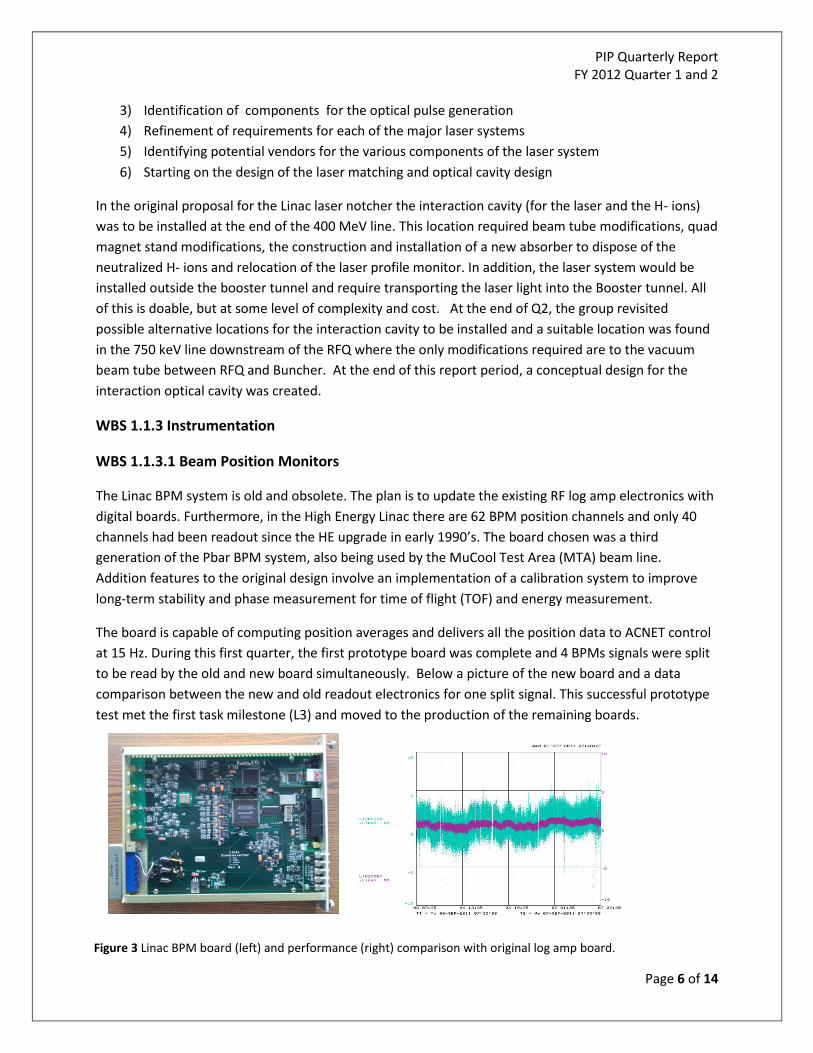
The board is capable of computing position averages and delivers all the position data to ACNET control
at 15 Hz. During this first quarter, the first prototype board was complete and 4 BPMs signals were split
to be read by the old and new board simultaneously. Below a picture of the new board and a data
comparison between the new and old readout electronics for one split signal. This successful prototype
test met the first task milestone (L3) and moved to the production of the remaining boards.
Figure 3 Linac BPM board (left) and performance (right) comparison with original log amp board.
PIP Quarterly Report FY 2012 Quarter 1 and 2
Page 7 of 14
WBS 1.1.4 Not Used
Some WBS numbering is nonconsecutive at lower levels because of account closings and
rearrangements after financial codes were initially established during the period of setting up PIP.
WBS 1.1.5 Utilities
The Linac Utilities, such as power distribution and vacuum systems are composed of mostly 40 year-
old equipment beyond its practical service life. There are two Level 4 elements in this WBS.
WBS 1.1.5.1 Power Distribution
The substation specifications were finalized and sent out for bid at the end of 2011. A presentation of
the plan was given at a PIP Status Report Meeting to the PIP upper management team and PIP
members. The contract was awarded early February 2012 to Federal Pacific at a cost approximately 8%
lower than expected. The estimate date for delivery is June 2012.
In addition to the L3 transformer upgrade, the Motor Control Center (hereafter referred as MCC) task,
which was originally planned for FY13, was moved to FY12. The rationale for changing the original RLS
schedule was based on the scheduling advantages of installing MCC in conjunction with L3 transformer
during the long lab wide Shutdown 2012 due to the impact on the level of powering off the whole 200
MHZ system. Therefore, in February the bid process was initiated and a contract awarded with Siemens
was completed in the same month at a cost of approximately $50,000.00. Lately, the activities have
been concentrated in developing the installation plan for both systems.
WBS 1.1.5.2 Not Used
Some numbering is nonconsecutive at lower levels because of account closings and rearrangements
after financial codes were initially established.
WBS 1.1.5.3 Vacuum System
A cost estimate was created for upgrading vacuum components in the Linac. Potential vendors have
been identified and contact for quotes on the root blower stations. A presentation of the plan was given
at a PIP Status Report Meeting to the PIP upper management team and PIP members.
WBS 1.2 Booster
The PIP effort for the Booster Accelerator is similar in some basic ways to the LINAC due to the age of
both accelerators being 40+ years in operations. The task structure also mirrors that of the LINAC in
many ways. However there are significant differences and concerns for the two accelerators.
PIP Quarterly Report FY 2012 Quarter 1 and 2
Page 8 of 14
The Proton Source Department has been working for years to increase the number of cycles that have
beam. To reach beam on every cycle (15Hz operation), the RF systems are being upgraded. Several years
ago, development of a modern power system for the RF, solid state, was shown to work. During the last
two years a final design was settled upon and two RF stations were upgraded to solid state. With PIP,
the remaining 17 stations will be upgraded. However, the RF cavities and tuner systems themselves are
the original equipment and cannot run beam on every pulse due to overheating. The cavities and tuners
are being refurbished to provide the needed additional cooling. The components are being cleaned-up,
tested at 15Hz before re-installation. In addition to the near-term refurbishment, new tuners and
cavities will be built.
Besides the vulnerable RF cavities-tuners, PIP addresses the aging infrastructure. The low conductivity
water system has developed leaks over the years which will addressed by replacing pumps and valves.
The vacuum system has antiquated components and will be replaced with modern equipment. The
electrical transformers will be replaced as well.
With the larger proton beam flux, the possibility of more beam loss and activation of Booster equipment
is a concern. Systems and procedures for operations are being developed and implemented to reduce
beam loss and in certain circumstances contain beam losses. The goal is to not increase the amount of
beam loss and activation as the proton flux essentially doubles.
WBS 1.2.1 RF
WBS 1.2.1.1 Anode Supply
Work was done on initial design for the anode supplies which will replace the 40 year old operating
system. The work is based upon the Main Injector anode supplies.
WBS 1.2.1.2 Bias Supply
Testing of a spare bias supply to measure the temperatures of heat sinks and silicon-controlled rectifiers
(SCRs) was done in preparation for procurement. The specifications for the bias supply transformer are
being developed for procurement of a prototype.
WBS 1.2.1.4 Not Used
Some WBS numbering is nonconsecutive at lower levels because of account closings and
rearrangements after financial codes were initially established during the period of setting up PIP.
WBS 1.2.1.4 Cavity Test Stand
A description of the layout and setup for a test stand was produced. ES&H is reviewing the proposed
shielding of the test stand. The shielding is necessary due to the activation of the tuners and cavities as
well as for x-rays produced during testing. RF equipment from the Tevatron will not be moved and
equipment will not be purchased until final ES&H approval to proceed with the test stand layout.
PIP Quarterly Report FY 2012 Quarter 1 and 2
Page 9 of 14
WBS 1.2.1.5 Cavity and Tuners Refurbishment
The first cavity and tuner set were removed after the termination of the Tevatron collider program. The
cavity was known to have vacuum issues and proved to be difficult to repair. A series of tests at several
rates and power were performed to measure temperatures at different locations on the cavity, tuners
and connections. A team learned to dismantle, repair and re-assemble the tuners. The refurbished
cavity-tuners system final test was to run at 15Hz at full power for several days while monitoring the
temperatures. The connection between the tuners and cavity were troublesome. The tolerance for
these connections is more stringent than had been necessary before for operations as well as what was
expected. Every time that the temperature of a connection was too large, it would take several days to
disconnect from the test setup, redo the tuner-cavity connection and re-establishing the test. After
successfully passing the final test after refurbishment, the cavity-tuners was not re-installed, as well as
the removal of a second cavity-tuners, since the laboratory deemed operation was most important; the
exchange of cavity-tuners will take place at the beginning of the FY12 shutdown. Table 3 below gives
our current timetable.
WBS 1.2.1.6 New Tuners
Two types of ferrites are needed for the tuners. Ferrites provided by potential vendors are being tested.
Low power testing showed that no samples met the larger magnetic permeability specification; a vendor
has sent a second set of samples. We are also making a high power testing setup for the ferrites. After
vendors for ferrites are qualified; we will order the first set of ferrites and procure the remaining
materials for making tuners.
WBS 1.2.1.7 New Cavities
A model is being developed of the current Booster RF cavities. The temperature measurements taken as
part of the refurbishment task are being used to benchmark the model. We are looking to make
improvements of the current design to increate the aperture as well as eliminate potential hot spots
(potential failure points).
WBS 1.2.1.8 Cavity 1013
With spare and left over material from the original building of RF Booster cavities, there is enough to
build an additional cavity. It has become obvious why certain pieces were not used originally; these
pieces are being reworked such that all of the pieces will fit together to form a functional cavity. The
original goal was to replace an operational cavity before the FY12 shutdown; with this not being
possible, the priority for this task will be lowered.
WBS 1.2.2 Accelerator Physics
WBS 1.2.2.1 Simulations and Studies
PIP Quarterly Report FY 2012 Quarter 1 and 2
Page 10 of 14
Studies have been on-going with the development of data acquisition methods and procedures. Data
have been collected throughout the Booster ramp cycle and then been analyzed. These results have
been compared to the simulations. In cases of disagreement, studies were done to validate the data
and/or check the simulations input.
WBS 1.2.2.2 Alignment and Aperture
As with the studies above, development of data acquisition methods and procedures have been done.
Data analysis shows the locations where the aperture is small. Based upon the limiting aperture
locations, a proposed first magnet move-alignment has been worked out. The move, re-taking of
aperture data and analysis will be done early within the FY12 shutdown.
WBS 1.2.2.3 Booster Notcher
The main person for the original design and work retired at the end of FY11; a new level 4 manager was
identified in December. An internal review of the notcher was done in February; adjustment to the
design and implementation are being/going to be done according to the reviewers’ recommendations.
In particular, we are looking to include additional shielding material by performing additional MARS
simulations. The basic components of the absorber have been ordered. The basic components of the
absorber will be assembled and tested before final installation during the FY12 shutdown. Preparations
for moving the notcher kickers and associated power system have done; the movement of these items
will occur during the FY12 shutdown.
WBS 1.2.2.4 Booster Cogging
Based upon the current cogging equipment, initial code development for the new magnetic cogging
method-system has been done.
WBS 1.2.2.5 Booster Collimation
The collimation task is to control Booster beam loss after implementing the above notcher and cogging
systems.
WBS 1.2.2.6 Radiation Shielding
There are on-going discussion and simulations of the material to be put into the Booster penetrations
for shielding purposes.
WBS 1.2.3 Instrumentation
WBS 1.2.3.1 Beam Position Monitors
Design work for the Booster beam position monitor system will begin after completion of the Linac
beam position monitor system.
WBS 1.2.3.2 Dampers
PIP Quarterly Report FY 2012 Quarter 1 and 2
Page 11 of 14
Work defining the hardware requirements for the longitudinal damper system was started.
WBS 1.2.4 Not Used
Some WBS numbering is nonconsecutive at lower levels because of account closings and
rearrangements after financial codes were initially established during the period of setting up PIP.
WBS 1.2.5 Utilities
WBS 1.2.5.1 Low Conductivity Water System
During the FY12 shutdown, the low conductivity water system will be upgraded. The work has been
specified, bid and contracted. Procurements for the part of the upgrade being done by Fermilab
personnel have been done.
WBS 1.2.5.2 Power Distribution
Transformer design will be based upon recent new equipment implemented at Fermilab and will start
after the Linac transformer is installed during the long shutdown.
WBS 1.2.5.3 Vacuum System
Vendor quotes are being acquired for vacuum equipment needed for the upgrade. Purchasing will occur
soon. The goal is to replace some of the aged components during the FY12 shutdown.
WBS 1.2.7 Solid State Upgrade
The Booster RF solid state upgrade has been going on piecemeal for several years with purchasing of
enough components to assemble the main elements of the solid state system: power amplifier, driver
module and modulator. With the Proton Improvement Plan, we have been able to buy components in
quantities. We have procured enough to complete ten power amplifiers, driver modules and
modulators. We have started the procurement of the remaining components to complete the upgrade.
With the termination of the Tevatron program, some labor resources were allocated to work on
assembly of the three main elements. Five power amplifiers, ten driver modules and four modulators
have been assembled. The assembly processes have become more parallelized and time to assemble
each main element is decreasing. The increased production rate has been factor into the schedule and
completion of the solid state is expected to be finished during FY13.
Table 3 Solid State and Cavity Refurbishment Time Table
BRF
Solid
State Cavity 15Hz Status
Date
Removed
Planned
Install
Date
Installed
1 X 11/12/2012 1/2/2013
2 X 10/15/2012 11/29/2012
PIP Quarterly Report FY 2012 Quarter 1 and 2
Page 12 of 14
X= SS Upgrade Completed, X = Cavity Refurbishment Completed
WBS 1.3 RFQ
The RFQ effort for the first two quarters FY12 has been extensive. The entire line up though the test
diagnostic line has been installed and tested.
Two magnetron plasma sources
LEBT (Solenoids, Trims, Eiznel Len)
201.25 MHz RFQ
All associated vacuum, power and diagnostics components
Diagnostic Line (Wires, emittance scanners, toroid, spectrometer magnet )
The beam testing has been very successful up to the RFQ. The current, efficiency and emittances look
good. However, a major problem was found when the beam energy was measured. The output beam
energy of the RFQ is not the required 750 KeV but approximately 710 KeV. This is currently being
worked on and is expected to cause a delay in the planned installation later in FY12. Work on the MEBT
planned for the 2nd quarter FY12 was delayed due to labor needed to investigate the RFQ energy issue.
This budget summary section will be inclusive from the start of FY12 before a base lined fully burdened
schedule was produced. Since that time, the PIP has ramped up budgeting and effort allocation
requirements to meet a RLS. Labor and cost estimates have undergone many changes in an effort to
firm up PIP goals and resource requirements. Tables 4 and graph 1 below show the status of PIP budget
with RLS estimates from the baseline budget created in February 2012. Variances in the RLS and actual
3 6/15/2012 9/10/2012 10/29/2012
4 6/15/2012 8/13/2012 9/24/2012
5 X 7/16/2012 8/27/2012
6 X 6/15/2012 7/30/2012
7 X cavity refurbishment underway 5/4/2012 6/15/2012
8 X X 10/8/2011 5/2/2012
9 8/15/2012 12/17/2012 1/28/2013
10 8/15/2012 1/14/2013 2/25/2013
11 2/15/2013 2/11/2013 3/25/2013
12 X 3/18/2013 4/29/2013
13 11/15/2012 4/15/2013 5/27/2013
14 11/15/2012 5/13/2013 7/1/2013
15 12/15/2012 7/15/2013 8/26/2013
16 12/15/2012 8/12/2013 9/30/2013
17 9/15/2012 9/16/2013 10/28/2013
18 9/15/2012 10/14/2013 11/25/2013
19 X 11/18/2013 12/30/2012
PIP Quarterly Report FY 2012 Quarter 1 and 2
Page 13 of 14
PIP numbers are due largely to less labor being available compared to PIP RLS requests and some
purchases in the second quarter being delayed due to the FY12 shutdown.
Table 4 PIP Year to Date Budget Summary (including requisitions in process and includes 18% M&S and 88% labor burden) * represents 20% additional M&S budget allocation beyond the guidance that developed Table 1