6] Main Harness Connection 7] Control Cable Connection 8] Motion Alarm (option) 9] Lift/Lower Switch 10] Platform-Base Selector 11] Emergency Stop Switch 12] Circuit Breaker 13] Battery Gauge 14] Hour Meter 15] GP102 Load Sense Module 16] Overload Cutout Relay
1
15
6
9
10
11
12
13
14
8
7
2
4
16
35
March 2008 "2047ES / 2647ES / 3247ES" Service & Parts Manual - CE SpecificationsPage 5-14
SEVCON MOTOR SPEED CONTROLLER
The Sevcon Motor Speed Controller (MC-1) is a microprocessor designed with the expresspurpose of operating the D/C electric motor at varying speeds. The controller uses Pulse-WidthModulation (PWM) technology on the Ground side of the motor to control motor speed. Out ofconcern for operator safety and to prevent short-circuiting, the Controller monitors certain circuitsfor potential abnormalities. When the controller senses a problem it errs to the side of safety andstops all motor operation. The green LED will flash a code indicating the reason for the shutdown.
Refer to the LED Diagnostics Definitions and Sevcon Motor Speed Controller - Connections onthe following pages.
ART_2182
1
7
6
12
J5 Plug Pin Identification
PIN # WIRE # FUNCTION 1 22 B+ power input (power up) 2 17 Lift, Drive or Steer functions input (functions requiring motor) 3 18 Steer Requested (adds additional motor speed for steer) 4 3 Enable Switch signal input 5 21 Speed cut-back (24 Volts = full speed, 0 Volts = creep speed) 6 16 Motor Start Relay signal (GROUND signal to activate Motor Start Relay) 7 41 Lift Valve B- (provides GROUND signal to Lift Valve) 8 none none 9 14 Accelerator reference signal (3.6 Volts to Potentiometer) 10 none none 11 none none 12 none none
Cable Connection Identification B+ Battery Positive Cable from 250 AMP Fuse B- Negative Battery Cable and GROUND wire (15) connection M2 Motor Ground (Pulse-Width Modulated [PWM] variable speed control)
"2047ES / 2647ES / 3247ES" Service & Parts Manual - CE Specifications March 2008Page 5-15
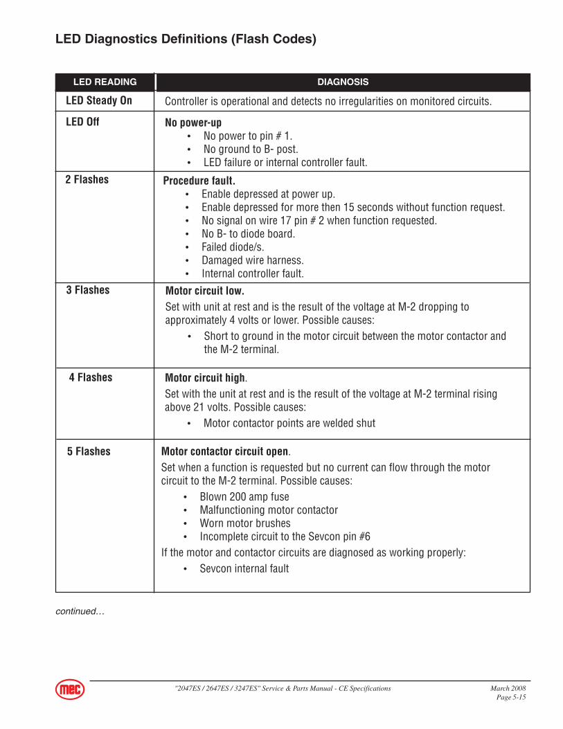
LED Steady On
LED Off
2 Flashes
3 Flashes
4 Flashes
5 Flashes
Controller is operational and detects no irregularities on monitored circuits.
No power-up• No power to pin # 1.• No ground to B- post.• LED failure or internal controller fault.
Procedure fault.• Enable depressed at power up.• Enable depressed for more then 15 seconds without function request.• No signal on wire 17 pin # 2 when function requested.• No B- to diode board.• Failed diode/s.• Damaged wire harness.• Internal controller fault.
Motor circuit low.Set with unit at rest and is the result of the voltage at M-2 dropping toapproximately 4 volts or lower. Possible causes:
• Short to ground in the motor circuit between the motor contactor andthe M-2 terminal.
Motor circuit high.Set with the unit at rest and is the result of the voltage at M-2 terminal risingabove 21 volts. Possible causes:
• Motor contactor points are welded shut
Motor contactor circuit open.Set when a function is requested but no current can flow through the motorcircuit to the M-2 terminal. Possible causes:
• Blown 200 amp fuse• Malfunctioning motor contactor• Worn motor brushes• Incomplete circuit to the Sevcon pin #6
If the motor and contactor circuits are diagnosed as working properly:• Sevcon internal fault
LED Diagnostics Definitions (Flash Codes)
continued…
LED READING DIAGNOSIS
March 2008 "2047ES / 2647ES / 3247ES" Service & Parts Manual - CE SpecificationsPage 5-16
6 Flashes
7 Flashes
8 Flashes
9 Flashes
Battery voltage fault.• This includes battery voltage below 12 volts or above 45 volts as
measured on pin #1.• This code will disable all functions.
Thermal cutback.• Sevcon internal temperatures above 176 degrees F.• Will limit motor speed in comparison with over temperature.• Resets when cooled.
Battery voltage at or below 18 volts• As measured on pin #1.• This code will interrupt or prevent lift function but will allow drive and
steer functions.When lift is interrupted due to a 9 flash, the electric motor will still run.
Accelerator fault.Set with unit at rest, a 6 flash will result in an 80% cutback of motor speed. TheAccelerator is the proportional control circuitry for the Sevcon. It works inconjunction with the potentiometer located in the upper control box, which isconnected to the joystick handle through a gear arrangement.
Measure voltage at terminals 14 and 15 on the platform terminalstrip or at the potentiometer plug connection.• With the joystick handle in neutral, 3.6 volts should be measured on
the accelerator circuit (wire #14).• Voltage proportionally decreases with the travel of the joystick, with
0 volts at full stroke.• With the joystick centered, voltages lower than 3.1 or higher than 3.9
will trigger a (6 flash) code.
LED Diagnostics Definitions (continued)
LED READING DIAGNOSIS
"2047ES / 2647ES / 3247ES" Service & Parts Manual - CE Specifications March 2008Page 5-17
FUNCTION VOLTAGE READING
Sevcon Motor Speed Controller - Connections
The following two pages describe the connections to the Sevcon Motor Speed Controller with abrief description of their function and the voltage measurements under normal conditions.
Important: Batteries must be fully charged before troubleshooting!A fully charged battery set on a 24 V DC system will have a nominalvoltage of 25.6 V DC
• Controller power-up and reference point for battery state-of-charge.
• Green LED indicates controller power-up.
• Power travels through the upper emergency-stop switch with uppercontrols selected.
• 7-Flash code and 9-flash code indicate low voltage at this terminal.
PIN 1 – WIRE 22 (WIRE 9 ON EARLY UNITS)Battery PositiveInput
Switched
5% less than battery voltage
• Controller begins the motor run sequence with this signal but still requiresa signal on pin 4 and a change on pin 9 before the motor will operate.
2047ES - Serial # 9801000 - 98010992647ES - Serial # 9901000 - 99011993247ES - Serial # 10001000 - 10001199 .................................................................................................... 6-2
2047ES - Serial # 9801100 - CURRENT2647ES - Serial # 9901200 - CURRENT3247ES - Serial # 10001200 - CURRENT................................................................................................... 6-4
Electric Schematics ............................................................................................................................................... 6-92047ES - Serial # 9801000 - 9801099
2647ES - Serial # 9901000 - 99011993247ES - Serial # 10001000 - 10001199 .................................................................................................. 6-10
2047ES - Serial # 9801100 - CURRENT2647ES - Serial # 9901200 - CURRENT3247ES - Serial # 10001200 - CURRENT................................................................................................. 6-12
March 2008 "2047ES / 2647ES /3247ES" Service & Parts Manual - CE SpecificationsPage 6-2
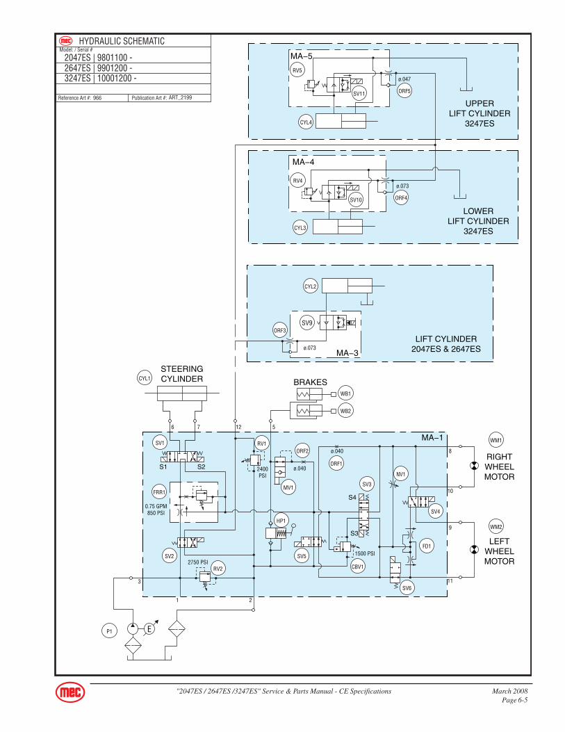
HYDRAULIC SCHEMATICS
2047ES - Serial # 9801000 - 98010992647ES - Serial # 9901000 - 99011993247ES - Serial # 10001000 - 10001199
ORF1 Orifice Plug, Wheel Motors Main Manifold (MA-1)ORF3 Orifice, Down Valve Lift Cylinder Manifold (MA-3), 2047ES and 2647ES onlyORF4 Orifice, Down Valve Lower Lift Cylinder Manifold (MA-4), 3247ES onlyORF5 Orifice, Down Valve Upper Lift Cylinder Manifold (MA-5), 3247ES only
P1 Pump Pump CompartmentPCF1 Steering Relief Flow Control Main Manifold (MA-1)RV1 Relief Valve, Lift Relief Main Manifold (MA-1)RV2 Relief Valve, Main Relief Main Manifold (MA-1)RV3 Relief Valve, Steering Main Manifold (MA-1)RV4 Relief Valve, Lift Cylinder Lower Lift Cylinder Manifold (MA-4), 3247ES onlyRV5 Relief Valve, Lift Cylinder Upper Lift Cylinder Manifold (MA-5), 3247ES onlySV1 Spool Valve, Steering Main Manifold (MA-1)SV2 Spool Valve, Lift Main Manifold (MA-1)SV3 Spool Valve, Drive Main Manifold (MA-1)SV4 Spool Valve, Decel Main Manifold (MA-1)SV5 Spool Valve, Torque Main Manifold (MA-1)SV6 Spool Valve, Torque Main Manifold (MA-1)SV7 Spool Valve, Brakes Main Manifold (MA-1)SV8 Poppet Valve, Down Main Manifold (MA-1), 2047ES and 2647ES onlySV9 Spool Valve, Down Lift Cylinder Manifold (MA-3), 2047ES and 2647ES only
SV10 Spool Valve, Down Lower Lift Cylinder Manifold (MA-4), 3247ES onlySV11 Spool Valve, Down Upper Lift Cylinder Manifold (MA-5), 3247ES onlyTP1 Test Port Main Manifold (MA-1)WB1 Wheel Brake Drive WheelWB2 Wheel Brake Drive WheelWM1 Wheel Motor, Right Side Machine BaseWM2 Wheel Motor, Left Side Machine Base
"2047ES / 2647ES /3247ES" Service & Parts Manual - CE Specifications March 2008Page 6-3
1 PUMP 2 TANK 3 TEST PORT 4 N/A 5 BRAKE 6 STEER 7 STEER 8 RIGHT B 9 LEFT A 10 RIGHT A 11 LEFT B 12 LIFT
MA1
MA3
MA4
MA5
March 2008 "2047ES / 2647ES /3247ES" Service & Parts Manual - CE SpecificationsPage 6-8
THIS PAGE INTENTIONALLY LEFT BLANK
"2047ES / 2647ES /3247ES" Service & Parts Manual - CE Specifications March 2008Page 6-9
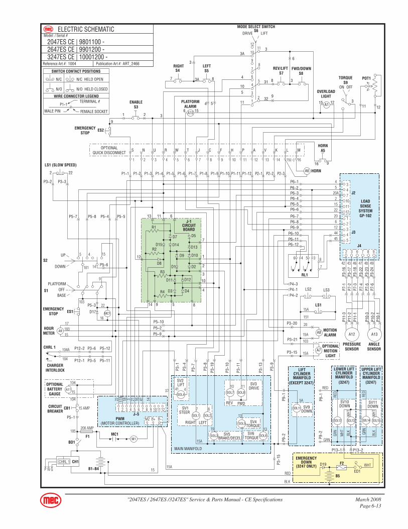
ELECTRIC SCHEMATICS
NOTES: (Unless otherwise specified)
1. Switch S1 BASE/PLATFORM makes contact from the CENTER to the LEFT positionwhen placed in BASE.
2. Switch S2 UP/DOWN makes contact from the CENTER to the LEFT position when theswitch is held in the CONTACT position and automatically returns to the CENTER positionwhen released.
3. Switch LS1 breaks the N/C set of contacts and makes the N/O set of contacts when theplatform reaches approximately 7 feet.
4. Switch LS2 and LS3 makes the N/C set of contacts when the Pothole Bars are down andlocked in place.
S1S2
ART_2236
ART_2470
LS1
A12
LS2 & LS3
March 2008 "2047ES / 2647ES /3247ES" Service & Parts Manual - CE SpecificationsPage 6-10
2047ES - Serial # 9801000 - 98010992647ES - Serial # 9901000 - 99011993247ES - Serial # 10001000 - 10001199
ITEM DESCRIPTION FUNCTION LOCATIONA1 OverloadLight, 28V Warn when Machine is Overloaded Upper Control BoxA5 Push-Button Switch Activates Horn On Upper Control BoxA6 Horn, 12V - 48V (option) Activated by Operator Under PlatformA7 Overload/Motion Alarm (option) Warn of Movement Outside Lower Control BoxA8 Motion Light (option) Warn of Movement Front Left Corner of MachineA9 Hour Meter Record Machine Usage Time Lower Control PanelA10 Platform Alarm Warn of Platform Overload and Tilt Upper Control BoxA12 Pressure Transducer Measure Lift Cyl Pressure for Load Sense Lift Cylinder ManifoldA13 Angle Transducer (Height Sensor) Measure Scissor Angle for Load Sense Lowest Scissor BeamA11 Battery Indicator Show Battery Status Lower Control PanelB1-4 6-V Deep Cycle Battery Power for Motor And Control Circuit Inside Battery CompartmentB5 12-V Battery Power for Emergency Down Circuit Battery Compartment, 3247ES ONLY
BD1 Battery Disconnect Switch Disconnect All Electrical Power Lower Control BoxCB1 Circuit Breaker, 15AMP Manual Control Circuit Protection Lower Control PanelCH1 Battery Charger Recharges 24-VDC Battery Pack Machine Base, Rear
CHRL1 Charger Relay Disconnect Electric when Charger ON Inside ChargerD1 - D15 Circuit Board Diodes Directs Signal to Proper Location Inside Lower Control Box
D17 Diode w/Ring Terminals Suppression Diode Across Contactor CoilD19 Diode w/Stud Base 10-32UNF-2A Emergency Down Battery Charger Battery CompartmentED1 Switch, Emergency Down Actuates Emergency Down Valves Battery Compartment, 3247ES ONLYES1 Switch, Emergency Stop Shut down All Moving Functions Lower Control PanelES2 Switch, Emergency Stop Shut down All Platform Functions Upper Control BoxF1 Fuse, 200AMP Main Line Fuse Inside Lower Control BoxF2 Fuse, 8AMP Emergency Down Fuse Battery Compartment, 3247ES ONLY
LS1 Limit Switch, Double Pole Enable Drive and High Speed Right Rear Corner of MachineLS2 Limit Switch, Single Pole Drive Enable if Pothole Deployed On pothole LinkageLS3 Limit Switch, Single Pole Enable Drive if Pothole Deployed On Pothole LinkageM1 Motor, 24V, 2HP Turn the Hydraulic Pump Pump Compartment
MC1 24-V Contactor Connects Battery (+) to Motor Inside Lower Control BoxPWM Controller, DC 250AMP Changes the Motor Speed Inside Lower Control BoxPOT1 Potentiometer, 20K Ohms Senses Operator Input Upper Control Box
R1 - R4 Circuit Board Resistors Inside Lower Control BoxRL1 Load Sense Relay Disable Functions if Platform Overloaded Lower Control BoxS1 Key Switch, N/O Contact Block Select Lower or Upper Controls Lower Control PanelS2 Switch, Toggle Lift/Lower at Lower Controls Lower Control PanelS3 Switch, Push Button Enable Other Functions at Platform Upper Control Box HandleS4 Switch, Micro Right Turn Switch Upper Control Box HandleS5 Switch, Micro Left Turn Switch Upper Control Box HandleS6 Switch, Toggle Select LIFT or DRIVE Upper Control BoxS7 Switch, Micro Reverse or Lift Switch Upper Control BoxS8 Switch. Micro Forward or Down Switch Upper Control BoxS9 Switch, Toggle TORQUE Switch Upper Control Box
SOL1 Coil, Turn Right Solenoid Activate Turn Right Valve (SV1) Main ManifoldSOL2 Coil, Turn Left Solenoid Activate Turn Left Valve (SV1) Main ManifoldSOL3 Coil, Decel Solenoid Activate Decel Valve (SV5) Main ManifoldSOL4 Coil, Lift Solenoid Activate Lift Valve (SV2) Main ManifoldSO5-6 Coil, Torque Solenoid Activate Torque Valves (SV4) (SV6) Main ManifoldSOL7 Coil, Reverse Solenoid Activate Reverse Valve (SV3) Main ManifoldSOL8 Coil, Forward Solenoid Activate Forward Valve (SV3) Main ManifoldSOL9 Coil, Brake Solenoid Activate Brake Valve (SV7) Main Manifold
SOL10 Coil, Down Solenoid Activate Down Valve (SV8) Main ManifoldSOL11 Coil, Down Solenoid Activate Down Valve (SV9) Lift Cylinder, 2047/2647 ONLYSOL12 Coil, Down Solenoid Activate Down Valve (SV10) Lower Lift Cylinder, 3247 ONLYSOL13 Coil, E-Down Solenoid Activate Emergency Down Valve (SV10) Lower Lift Cylinder, 3247 ONLYSOL14 Coil, Down Solenoid Activate Down Valve (SV11) Upper Lift Cylinder, 3247 ONLYSOL15 Coil, E-Down Solenoid Activate Emergency Down Valve (SV11) Lower Lift Cylinder, 3247 ONLY
"2047ES / 2647ES /3247ES" Service & Parts Manual - CE Specifications March 2008Page 6-11
ART_24651002
ELECTRIC SCHEMATICModel: / Serial #
Publication Art #:Reference Art #:
2047ES CE | 9801000 - 98010992647ES CE | 9901000 - 99011993247ES CE | 10001000 - 10001199
(EXCEPT 3247)
2047&
2647
SOL4
SOL1 SOL2
SOL3
SOL9
SOL5
SOL6
SOL10
SOL7 SOL8
SOL11REV FWD
41 4
7 8
19
19
10 11
SV5DECEL
SV7BRAKEMAIN
MANIFOLD
P3−1
9
P3−1
0
P3−1
1
P3−1
3
P3−9
13
13
5A
1
2
5A
SV2LIFT
SV9DOWN
SV1STEER
SV3DRIVE
RIGHT LEFTSV6
TORQUE
SV8DOWN
SV4TORQUE
LIFTCYLINDERMANIFOLD
LS3
WHTED1
F2
B5
D19EMERGENCYDOWN
(3247 ONLY)
BLKRED
RED
GRN
GRN
RED
RED
GRN
BLK
WHT
WHT
WHT
BLK
SOL12 SOL13 SOL14 SOL15
SV10DOWN
SV11DOWN
(3247) (3247)
LOWER LIFTCYLINDERMANIFOLD
UPPER LIFTCYLINDERMANIFOLD
1
2
MC1
A9
M1
A11
MODE SELECT SWITCHS6
HORNA5
ENABLES3
ES2EMERGENCYSTOP
DRIVE LIFT
OVERLOADLIGHT
PLATFORMALARM
REV/LIFT FWD/DOWN
33A
4
4
8
6
61 2 3
S
12
7
1
3
2
R2
R3
R4
D8
D15 D14
D9
D11
D10
10
4
D1 D2
D3 D4
D12
D7
D13
D5
R1
13
2
S2UP
DOWN
22
LS1 (SLOW SPEED)
11 6
9 5 814
P1−1
P5−4 P5−5
P5−6
P5−10P5−2P5−9
P5−8
P3−3P3−2
P5−7
P1−2 P1−3 P1−4 P1−5 P1−6 P1−7
P3−7
P3−8
P3−1
P12−2 P3−6 P5−12
P12−1 P3−5 P5−11
P5−1
CB1CIRCUITBREAKER
OPTIONALBATTERYGAUGE
CHRL 1
P3−4
LS2
LS1
(MOTOR CONTROLLER)PWM
J−5
MC1F1
CH1
P3−1
5
P1−8 P1−9 P1−10 P1−11 P1−12 P2−1 P2−2
P6−1P6−2P6−3P6−4P6−5P6−6
P6−7P6−8P6−9
P6−10P6−11P6−12
P3−20
P3−21
P3−15
P4−1P4−3
P4−2
MOTIONALARM
OPTIONALMOTIONLIGHT
P2−3
N U R W T J C F H P A V K L M
9
15
15 12A1
A10
A6
A8
A7
HORN
87 3
311 12
ON OFF
POT1TORQUES9
9
916
31
32
3
S4 S5 S7 S8
RIGHT LEFT
3A
105
5 11
OPTIONALQUICK DISCONNECT
103
S1
D17ES1
PLATFORM
BASEOFF
P5−3EMERGENCY
STOP
HOURMETER
J-1CIRCUITBOARD
1112
10
98
7
65
4
3
12
1 2 3 4 5 6 7 8 9 10
1 2
15A
15P N G
15
M2
105
104
104
104
104A
15
BD1
200 AMP
15 AMP
CHRL 1
B+ B−
B1−B4
3 4 5 6 7 8 9 10 11 12
22 17A
18 3 21 16 41 14
11 12 13 14 1615(–)
22
1617
15103
5 4
101
15
14
9
151
15A
20
15A
103
15A
CHARGERINTERLOCK
SWITCH CONTACT POSITIONS
N/C
N/O
N/C HELD OPEN
N/O HELD CLOSED
P1−1
WIRE CONNECTOR LEGENDTERMINAL #
FEMALE SOCKETMALE PIN
P7-1
P7-2
P7-3
P7-4
P7-5
P7-6
P11-
3P1
1-2
P11-
1
P10-
3P1
0-2
P10-
1
J2
J3
J4
LOADSENSE
SYSTEMGP-102
P3-1
6P3
-17
P3-1
8P3
-22
P3-2
3P3
-24
45
20A2
1522206
124445
42 43 46 47 48 49
347101112
12345
2 3 6 7 8 9
RL1
3546 8
7
PRESSURESENSOR
ANGLESENSOR
A12 A13
March 2008 "2047ES / 2647ES /3247ES" Service & Parts Manual - CE SpecificationsPage 6-12
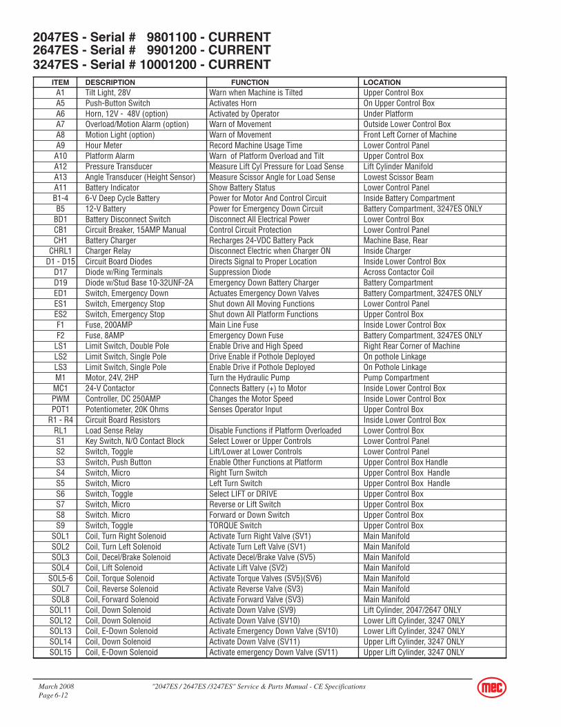
2047ES - Serial # 9801100 - CURRENT2647ES - Serial # 9901200 - CURRENT3247ES - Serial # 10001200 - CURRENT
ITEM DESCRIPTION FUNCTION LOCATIONA1 Tilt Light, 28V Warn when Machine is Tilted Upper Control BoxA5 Push-Button Switch Activates Horn On Upper Control BoxA6 Horn, 12V - 48V (option) Activated by Operator Under PlatformA7 Overload/Motion Alarm (option) Warn of Movement Outside Lower Control BoxA8 Motion Light (option) Warn of Movement Front Left Corner of MachineA9 Hour Meter Record Machine Usage Time Lower Control PanelA10 Platform Alarm Warn of Platform Overload and Tilt Upper Control BoxA12 Pressure Transducer Measure Lift Cyl Pressure for Load Sense Lift Cylinder ManifoldA13 Angle Transducer (Height Sensor) Measure Scissor Angle for Load Sense Lowest Scissor BeamA11 Battery Indicator Show Battery Status Lower Control PanelB1-4 6-V Deep Cycle Battery Power for Motor And Control Circuit Inside Battery CompartmentB5 12-V Battery Power for Emergency Down Circuit Battery Compartment, 3247ES ONLY
BD1 Battery Disconnect Switch Disconnect All Electrical Power Lower Control BoxCB1 Circuit Breaker, 15AMP Manual Control Circuit Protection Lower Control PanelCH1 Battery Charger Recharges 24-VDC Battery Pack Machine Base, Rear
CHRL1 Charger Relay Disconnect Electric when Charger ON Inside ChargerD1 - D15 Circuit Board Diodes Directs Signal to Proper Location Inside Lower Control Box
D17 Diode w/Ring Terminals Suppression Diode Across Contactor CoilD19 Diode w/Stud Base 10-32UNF-2A Emergency Down Battery Charger Battery CompartmentED1 Switch, Emergency Down Actuates Emergency Down Valves Battery Compartment, 3247ES ONLYES1 Switch, Emergency Stop Shut down All Moving Functions Lower Control PanelES2 Switch, Emergency Stop Shut down All Platform Functions Upper Control BoxF1 Fuse, 200AMP Main Line Fuse Inside Lower Control BoxF2 Fuse, 8AMP Emergency Down Fuse Battery Compartment, 3247ES ONLY
LS1 Limit Switch, Double Pole Enable Drive and High Speed Right Rear Corner of MachineLS2 Limit Switch, Single Pole Drive Enable if Pothole Deployed On pothole LinkageLS3 Limit Switch, Single Pole Enable Drive if Pothole Deployed On Pothole LinkageM1 Motor, 24V, 2HP Turn the Hydraulic Pump Pump Compartment
MC1 24-V Contactor Connects Battery (+) to Motor Inside Lower Control BoxPWM Controller, DC 250AMP Changes the Motor Speed Inside Lower Control BoxPOT1 Potentiometer, 20K Ohms Senses Operator Input Upper Control Box
R1 - R4 Circuit Board Resistors Inside Lower Control BoxRL1 Load Sense Relay Disable Functions if Platform Overloaded Lower Control BoxS1 Key Switch, N/O Contact Block Select Lower or Upper Controls Lower Control PanelS2 Switch, Toggle Lift/Lower at Lower Controls Lower Control PanelS3 Switch, Push Button Enable Other Functions at Platform Upper Control Box HandleS4 Switch, Micro Right Turn Switch Upper Control Box HandleS5 Switch, Micro Left Turn Switch Upper Control Box HandleS6 Switch, Toggle Select LIFT or DRIVE Upper Control BoxS7 Switch, Micro Reverse or Lift Switch Upper Control BoxS8 Switch. Micro Forward or Down Switch Upper Control BoxS9 Switch, Toggle TORQUE Switch Upper Control Box
SOL1 Coil, Turn Right Solenoid Activate Turn Right Valve (SV1) Main ManifoldSOL2 Coil, Turn Left Solenoid Activate Turn Left Valve (SV1) Main ManifoldSOL3 Coil, Decel/Brake Solenoid Activate Decel/Brake Valve (SV5) Main ManifoldSOL4 Coil, Lift Solenoid Activate Lift Valve (SV2) Main Manifold
SOL5-6 Coil, Torque Solenoid Activate Torque Valves (SV5)(SV6) Main ManifoldSOL7 Coil, Reverse Solenoid Activate Reverse Valve (SV3) Main ManifoldSOL8 Coil, Forward Solenoid Activate Forward Valve (SV3) Main Manifold
SOL11 Coil, Down Solenoid Activate Down Valve (SV9) Lift Cylinder, 2047/2647 ONLYSOL12 Coil, Down Solenoid Activate Down Valve (SV10) Lower Lift Cylinder, 3247 ONLYSOL13 Coil, E-Down Solenoid Activate Emergency Down Valve (SV10) Lower Lift Cylinder, 3247 ONLYSOL14 Coil, Down Solenoid Activate Down Valve (SV11) Upper Lift Cylinder, 3247 ONLYSOL15 Coil, E-Down Solenoid Activate emergency Down Valve (SV11) Upper Lift Cylinder, 3247 ONLY
"2047ES / 2647ES /3247ES" Service & Parts Manual - CE Specifications March 2008Page 6-13
ART_24661004
ELECTRIC SCHEMATICModel: / Serial #
Publication Art #:Reference Art #:
2047ES CE | 9801100 -2647ES CE | 9901200 -3247ES CE | 10001200 -
RED
GRN
WHT
GRN
RED
RED
GRN
BLK
WHT
WHT
WHT
BLK
SOL12 SOL13 SOL14 SOL15
SV10DOWN
SV11DOWN
ED1
F2
B5
D19
(3247) (3247)
LOWER LIFTCYLINDERMANIFOLD
EMERGENCYDOWN
(3247 ONLY)
UPPER LIFTCYLINDERMANIFOLD
P9−1
P9−2
P13−1 P13−2
BLK
RED
LS3
MC1
A9
SOL4
SOL1 SOL2
SOL3
SOL5
SOL6
SOL7 SOL8
M1
A11
(EXCEPT 3247)
LIFTCYLINDERMANIFOLD
5A
SOL11 SV9DOWN
MODE SELECT SWITCHS6
HORNA5
ENABLES3
ES2EMERGENCYSTOP
DRIVE LIFT
OVERLOADLIGHT
PLATFORMALARM
REV/LIFT FWD/DOWN
33A
4
4
8
6
61 2 3
S
12
7
1
3
2
R2
R3
R4
D8
D15 D14
D9
D11
D10
10
4
D1 D2
D3 D4
D12
D7
D13
D5
R1
13
2
S2UP
DOWN
22
LS1 (SLOW SPEED)
11 6
9 5 814
P1−1
P5−4 P5−5
P5−6
P5−10P5−2P5−9
P5−8
P3−3P3−2
P5−7
P1−2 P1−3 P1−4 P1−5 P1−6 P1−7
P3−7
P3−8
P3−1
P12−2 P3−6 P5−12
P12−1 P3−5 P5−11
P5−1
CB1CIRCUITBREAKER
OPTIONALBATTERYGAUGE
CHRL 1
P3−4
P3−1
9
P3−1
0
P3−1
1
P3−1
3
P3−9
LS2
SV2
SV5 SV6
SV4
SV1STEER
DRIVESV3
LS1
J2
J3
J4
RL1
LOADSENSE
SYSTEMGP-102
P9−1
LIFT
(MOTOR CONTROLLER)PWM
J−5
MC1F1
CH1
RIGHT LEFT
BRAKE/DECEL
MAIN MANIFOLD
TORQUE
TORQUE
REV FWD
P9−2
P3−1
5
P1−8 P1−9 P1−10 P1−11 P1−12 P2−1 P2−2
P6−1P6−2P6−3P6−4P6−5P6−6
P6−7P6−8P6−9
P6−10P6−11P6−12
P3-1
6P3
-17
P3-1
8P3
-22
P3-2
3P3
-24
P3−20
P3−21
P3−15
P4−1P4−3
P4−2
MOTIONALARM
PRESSURESENSOR
ANGLESENSOR
OPTIONALMOTIONLIGHT
P2−3
N U R W T J C F H P A V K L M
9
15
15 12A1
A10
A6
A8 A12
A7
HORN
87 3
311 12
ON OFF
POT1TORQUES9
9
916
31
32
3
S4 S5 S7 S8
RIGHT LEFT
3A
105
5 11
OPTIONALQUICK DISCONNECT
103
S1
D17ES1
PLATFORM
BASEOFF
P5−3EMERGENCY
STOP
HOURMETER
J-1CIRCUITBOARD
1112
10
98
7
65
4
3
12
1 2 3 4 5 6 7 8 9 10
41 4
1 2
15A15P N G
15
M2
105
104
104
104
104A
15
BD1
200 AMP
15 AMP
CHRL 1
B+ B−
B1−B4
3 4 5 6 7 8 9 10 11 12
22 17A
18 3 21 16 41 14
7 8
19
13
13
15A
10 11
11 12 13 14 1615(–)
22
1617
15103
5 4
101
15
14
9
45
20A2
1522206
124445
42 43 46 47 48 49
347101112
12345
151
15A
20
15A
103
15A
3546 8
7
CHARGERINTERLOCK
2 3 6 7 8 9
A13
SWITCH CONTACT POSITIONS
N/C
N/O
N/C HELD OPEN
N/O HELD CLOSED
P1−1
WIRE CONNECTOR LEGENDTERMINAL #
FEMALE SOCKETMALE PIN
P7-1
P7-2
P7-3
P7-4
P7-5
P7-6
P11-
3P1
1-2
P11-
1
P10-
3P1
0-2
P10-
1
March 2008 "2047ES / 2647ES /3247ES" Service & Parts Manual - CE SpecificationsPage 6-14