Frontiers in Manufacturing Engineering (FME) ISSN: 2329-8227 (Print) ISSN: 2329-8219 (Online) CODEN : FMERA8 Frontiers in Manufacturing Engineering (FME) 4(2) (2020) 01-06 Cite The Article: Arun Bhiva Rane (2020). Improvement of Core Manufacturing in Foundry. Frontiers in Manufacturing Engineering, 4(2) : 01-06. DOI: http://doi.org/10.7508/fme.02.2020.01.06 IMPROVEMENT OF CORE MANUFACTURING IN FOUNDRY Arun Bhiva Rane Associate Professor, University of Mumbai, India * Corresponding Author E-mail: [email protected]This is an open access article distributed under the Creative Commons Attribution License, which permits unrestricted use, distribution, and reproduction in any medium, provided the original work is properly cited. ARTICLE DETAILS ABSTRACT Article History: No metalworking process has the ability to form external and internal contours, shapes, cavities, and so foundry operation is important. Due to competitor’s pressure, metal caster’s has to refine current processes. They need to develop new technologies that improve productivity and reduce costs. Core-making is heart of metal casting. Core making process is one area, where foundries can improve process efficiencies and cost savings. This report investigates the possibilities and methods to reduce the time of the core production process in reputed casting company in order to increase the production. After understanding current process, bottleneck operations and root cause were identified. Most significant causes selected were; To reduce the cycle time of the machine, to eliminate the time lost in waiting due to unavailability of core sand, and to reduce the pattern changing time. Eighteen possible solutions were suggested. As per the suggested possible remedies, cycle time can be reduced by 17% to 35% while rate of production can be increased by 64% to 107% successfully by cold-box production system. Also Sand, resin, catalyst and additives can be metered precisely to improve quality. Thus higher quality cores can be produced by properly integrated core-production system. Operations can be automated to further improve the production and quality by observing trade-off between cost and productivity. KEYWORDS Casting, Foundry, Casting cores, Binders, Cycle time. 1. INTRODUCTION Very few papers are available in this domain. Venkataraman has demonstrated case studies to improve core making and hence productivity [1]. Sitko has addressed supply chain issues to improve efficiency of Foundry [2]. According to Reference, the best composition for making core was found to be 2.5% starch, 2.5% clay, 8% oil, 8% moisture and 68% sand [3]. It was baked at 150 o C for 1 h 30min. The tensile strength of the core was observed to be 600 KN/m 2 . Fast and efficient metal cleaners help to remove residual binder/release agent build-up. Clean tooling improves Core manufacturing processes, and hence the productivity. Fayomi et al. analysed sand to improve and develop an efficient foundry core [4]. The mechanical properties of sand were determined to give good moulding properties and core durability. It was demonstrated that Ochadamu sand and clay have good values as a binder for foundry core making. According to Reference, mechanization of the process of core making depends on core blowing machines [5]. Cold-box, hot-box and warm-air technologies require that core blowing machines shall be additionally equipped with either core-box pre-heating system or gas purging and neutralization system, or hot air purging systems. Hence production of universal core blowing machines equipped with replaceable devices has been undertaken in Poland. Bhimani et al. presented better cores with good quality foundry sand [6]. Joshi and Jugulkar have minimised the problems, to improve the productivity and profit of foundry [7]. Czerwinski et al. offered basic technical characteristics of salt and sand cores to improve productivity [8]. Deore et al. have discussed various types of cores which can be used in foundry along-with their manufacturing processes [9]. Gupta et al. has discussed issues like more core strip out time, more core box clamping time, heavy core boxes etc. in manual core making process [10]. Kawale et al. have demonstrated Quality circle as management tool to enhance the productivity in foundry [11]. Jaiswal et al. have used lean manufacturing to improve productivity in Foundry [12]. Song et al. improved the performance of sand core by using the modified water glass as a binder and adding powder additives in the sand hardening process [13]. Reference [14] filed patent for magnetic core manufacturing method which will give high strength and high resistivity to core. Thus less efforts are seen to improve productivity of Core making. So, objectives of this study are, ① To reduce the cycle time of the core making on the machine. ② To eliminate the time lost in waiting due to unavailability of core sand. ③ To reduce the pattern changing time. 2. METHODOLOGY Existing process flow is studied first. Then process of Core making Received 13 January 2021 Accepted 2 March 2021 Available online 11 March 2021 ARTICLE
Frontiers in Manufacturing Engineering (FME) 4(2) (2020) 01-06
Cite The Article: Arun Bhiva Rane (2020). Improvement of Core Manufacturing in Foundry. Frontiers in Manufacturing Engineering, 4(2) : 01-06.
DOI: http://doi.org/10.7508/fme.02.2020.01.06
IMPROVEMENT OF CORE MANUFACTURING IN FOUNDRYArun Bhiva Rane
Associate Professor, University of Mumbai, India*Corresponding Author E-mail: [email protected]
This is an open access article distributed under the Creative Commons Attribution License, which permits unrestricted use, distribution, and reproduction in any medium, provided the original work is properly cited.
ARTICLE DETAILS ABSTRACT
Article History: No metalworking process has the ability to form external and internal contours, shapes, cavities, and so foundry operation is important. Due to competitor’s pressure, metal caster’s has to refine current processes. They need to develop new technologies that improve productivity and reduce costs. Core-making is heart of metal casting. Core making process is one area, where foundries can improve process efficiencies and cost savings. This report investigates the possibilities and methods to reduce the time of the core production process in reputed casting company in order to increase the production. After understanding current process, bottleneck operations and root cause were identified. Most significant causes selected were; To reduce the cycle time of the machine, to eliminate the time lost in waiting due to unavailability of core sand, and to reduce the pattern changing time. Eighteen possible solutions were suggested. As per the suggested possible remedies, cycle time can be reduced by 17% to 35% while rate of production can be increased by 64% to 107% successfully by cold-box production system. Also Sand, resin, catalyst and additives can be metered precisely to improve quality. Thus higher quality cores can be produced by properly integrated core-production system. Operations can be automated to further improve the production and quality by observing trade-off between cost and productivity.
Very few papers are available in this domain. Venkataraman has demonstrated case studies to improve core making and hence productivity [1]. Sitko has addressed supply chain issues to improve efficiency of Foundry [2]. According to Reference, the best composition for making core was found to be 2.5% starch, 2.5% clay, 8% oil, 8% moisture and 68% sand [3]. It was baked at 150oC for 1 h 30min. The tensile strength of the core was observed to be 600 KN/m2. Fast and efficient metal cleaners help to remove residual binder/release agent build-up. Clean tooling improves Core manufacturing processes, and hence the productivity. Fayomi et al.analysed sand to improve and develop an efficient foundry core [4]. The mechanical properties of sand were determined to give good moulding properties and core durability. It was demonstrated that Ochadamu sand and clay have good values as a binder for foundry core making.
According to Reference, mechanization of the process of core making depends on core blowing machines [5]. Cold-box, hot-box and warm-air technologies require that core blowing machines shall be additionally equipped with either core-box pre-heating system or gas purging and neutralization system, or hot air purging systems. Hence production of universal core blowing machines equipped with replaceable devices has been undertaken in Poland. Bhimani et al. presented better cores with good quality foundry sand [6].
Joshi and Jugulkar have minimised the problems, to improve the productivity and profit of foundry [7]. Czerwinski et al. offered basic
technical characteristics of salt and sand cores to improve productivity [8]. Deore et al. have discussed various types of cores which can be used in foundry along-with their manufacturing processes [9]. Gupta et al. has discussed issues like more core strip out time, more core box clamping time, heavy core boxes etc. in manual core making process [10]. Kawale et al. have demonstrated Quality circle as management tool to enhance the productivity in foundry [11]. Jaiswal et al. have used lean manufacturing to improve productivity in Foundry [12].
Song et al. improved the performance of sand core by using the modified water glass as a binder and adding powder additives in the sand hardening process [13]. Reference [14] filed patent for magnetic core manufacturing method which will give high strength and high resistivity to core.
Thus less efforts are seen to improve productivity of Core making. So, objectives of this study are,
① To reduce the cycle time of the core making on the machine.
② To eliminate the time lost in waiting due to unavailability of core sand.
③ To reduce the pattern changing time.
2. METHODOLOGY
Existing process flow is studied first. Then process of Core making
Received 13 January 2021 Accepted 2 March 2021 Available online 11 March 2021
ARTICLE
2 Frontiers in Manufacturing Engineering (FME) 4(2) (2020) 01-06
Cite The Article: Arun Bhiva Rane (2020). Improvement of Core Manufacturing in Foundry. Frontiers in Manufacturing Engineering, 4(2) : 01-06.
and sand preparation is studied in detail. There are two types of Cold box machines on which time study is performed. Waiting time and pattern changing time is observed. Current output is recorded. Finally, methodology is proposed with expected outcome.
2.1 Existing process flow
The existing process flow is given in Table 1.
2.2 Process of Core making
Core is a material introduced into the mould for making hollow cavities in a casting. This work concentrates on the Cold-box machine core making process. The flow is given in Figure 1. Cores are surrounded by molten metal in the mould cavity. Therefore, it should have high refractoriness, permeability and strength. Hence, the sand used in core has to be superior than the sand used in mould.Core Sand is fed into the sand hopper which is then fed into the sand magazine. The sand magazine then injects the sand into the pattern. After injection, the sand magazine gets disengaged and the blow bush plate gets engaged. The amine gases provided by the gas chamber are then inserted through the blow bush plate. The amine gases make the sand particles hold together tightly. The blow bush plate is then disengaged and the top ejection plate engages and ejects the top pattern. The bottom pattern along with the core slides out and then the pins in the bottom ejection plate eject the core. Thus, the core is obtained. The bottom pattern slides in and the cycle is repeated. This plant has two types of mahines,
Type 1. CB800 60 Liter Cold Box Shooter:
Max. Core Wt. = 60 kg
Type 2. CB600 30 Liter Cold Box Shooter:
Max. Core Wt. = 30 kg
The only difference is that, in type 2, the top ejection trolley is missing. The ejection is done by hand and the blow plate does not have any bushes.
2.3 Preparation of Core sand
Core sand is prepared by adding binder system to the silica sand. The binder system consists of three parts Part A, Part B, Part C. Part A is Phenolic Resin, Part B is Isocyanide and Part C is Tri ethyl amine. Part A, Part B, Part C blended together is 1%, 1%, 0.1% of silica sand. Core sand properties are determined on the basis of five factors, namely:
Bench Life
Compression Strength
Tensile Strength
Scratch Hardness
Gas Content
The sand is fed into the sand hopper manually via a trolley which is filled through a gating system provided at the mixer.
2.4 Time study on Machines
Time required for various operations are recorded in Table 2 for both the machines.
(1) Type 1 Machine
Sand hopper capacity = 300 kg
Core Wt. = 43.5 kg
No. of cores made/pattern = 2
Total wt. of sand fed in pattern/cycle = 87 kg
Cycle time for two cores = 5 min 47 sec
In one sand feed,
Table 1: Process flow.
Op. no. Operation description
10 Receipt of raw material
20 Inspection of raw material
30 Storage of raw material
40 Core making
50 Return cooling sand for moulding
60 Sand preparation
70 Pattern inspection
80 Mounting of pattern on moulding machine
90 Moulding
100 Core setting
110 Filter placement
120 Mould cleaning
130 Mould closing
140 Metal charging
150 Melting
160 Pouring
170 Knock out
180 Shot blasting
190 Visual inspection
200 Wedge breaking
210 As per final control plan
220 Material movement for fettling and finishing
230 Fettling and finishing
240 Receipt of material from subcontractor for fettling
250 Inspection
260 Re shot blasting
270 Painting
280 Final inspection
290 Packaging
300 Storage and dispatch
Figure 1: Core making on Cold box machine
3Frontiers in Manufacturing Engineering (FME) 4(2) (2020) 01-06
Cite The Article: Arun Bhiva Rane (2020). Improvement of Core Manufacturing in Foundry. Frontiers in Manufacturing Engineering, 4(2) : 01-06.
by trolley from one hopper to another)
③ As the third cycle is going on, type 1 machine operation is halted because of unavailability of sand.
④ Similarly, type 2 machine operation is halted in the corresponding cycles.
After approximately every 45 min, the operators at all machines have to wait for 15-20 min for sand hopper to get filled.
2.6 Pattern changing time
The time required for core box pattern changing is approximately 90 min.
This is because of the unorganized storage of the core boxes and strenuous methods of clamping and unclamping the core box in the machine.
2.7 Output of cores
In an hour, the machine run-time is approximately 45 min. at present. In proposed condition, machine is operational for the complete hour. It is assumed that 22 hours are available in a day. The current observed output is given in Table 3.
3. PROPOSED ACTION
Methodology proposed is as under.
3.1 To reduce the Cycle time on the machine
Following actions are proposed.
① Maintenance of the gate of the mixer:
The gate of the mixer used to shift the core sand in the trolleys has a hinge which wears out after operating the gate for around 1000 times. As it wears out, the operator faces difficulty to open and close the gate. This results in loss of time. Proper maintenance (oiling) and periodic changing of the gate will reduce the time taken to shift the core sand.
② Cleaning Time Reduction (Auto Cleaning Process):
After the completed core is removed from the machine, the operator cleans the pattern so that any dry sand stuck in the slots (provided to escape air) is blown out. The cleaning time taken varies from operator to operator ranging from 60-200 sec. By installing air blow vents above the slide to blow off the loose sand while coming out, using garclean spray and giving operators proper tips and assistance will help in reducing this time. In addition to this, if bushes are provided to the blow plate of type 2 machines, the time required to remove the sand accumulated on top of the pattern after blowing can be eliminated as well as core sand can be used much more resourcefully.
③ Provision of bushes in the blow plate (Type 2):
The gas plate in the type 2 cold box machine does not consist of any bushes. This causes the amine gas passed through it to leak because of not concentrated flow in the pattern. Since the flow is not concentrated, the gassing time required to make the sand particles in the pattern hold tightly
No. of cores produced = 6
Total wt. = 261 kg
(2) Type 2 Machine
Sand hopper capacity = 100 kg
Core Wt. = 21.45 kg
No. of cores made/pattern = 1
Total wt. of sand fed in pattern/cycle= 21.45kg
Cycle time for one core = 4 min 09 sec
In one sand feed,
No. of cores produced= 4
Total wt = 85.8 kg
2.5 Waiting time
Sand mixer capacity = 300 kg (Overloaded. Actual sand mixer capacity = 200kg)
Cycle time of sand mixer = 4 min
Filling sand in the mixer manually = 4 min 50 sec
Filling of resin and catalyst in the mixer manually = 1 min
Filling of trolley = 40 sec
Feeding sand core in the hopper = 30 sec
① After 1st cycle, the operator feeds 300kgs sand in type 1 machinetaking approximately 11 min. (feeding of components in mixture + cycle time + feeding of trolley + feeding of sand hopper)
② After 2nd cycle, the operator feeds 100kgs sand each in all machinestaking approximately 13 min. (feeding of components in mixture + cycle time + feeding of trolley + feeding of sand hopper + traveling time taken
Table 2: Time study.
Op. no. Operation description
Type 1 Type 2
Wt=87 kg Wt=21.45 kg
Time(Sec) Time(Sec)
1 Blow 5 3
2 Delay for exhaust 4 2
3 Exhaust 6 3
4 Sand removing 0 10
5 Blow bush plate engage 6 6
6 Lp gassing 20 12
7 Hp gassing 35 30
8 Blow bush plate disengage 6 6
9 Top ejection plate engage 6 0
10 Top Ejection Plate Disengage and pattern sliding out 8 8
11 Bottom ejection up 35 0
12 Core removing and cleaning 208 64
13 Loose piece assembly 0 91
14 Pattern sliding in 8 8
Total 347 243
Table 3: Observed production.
Type 1 Type 2
Wt = 87 kg Wt = 21.45 kg
Cycle time 347 243
Cycles / Hour 7 11
Cycles / Day 154 242
No. of Cores / Day 308 242
4 Frontiers in Manufacturing Engineering (FME) 4(2) (2020) 01-06
Cite The Article: Arun Bhiva Rane (2020). Improvement of Core Manufacturing in Foundry. Frontiers in Manufacturing Engineering, 4(2) : 01-06.
is kept more. This not only results in loss of time but also in foul smell.
④ Maintenance of the wheels of the blow bush plate (Type 1):
The wheels of the blow bush plate in the type 1 cold box machine are worn out because of their continuous use. Thus, while operation the blow bush plate is subjected to play. The play causes the plate to get stuck and bushes to be out of alignment with the holes provided in the pattern. This proper alignment to be done results in loss of time and amine gas tends to escape providing insufficient gassing and thus reduces core strength.
⑤ Proper mating of the pattern with the ejection pins:
If the core pattern and bottom ejection plate pins are not mated properly and if their alignment is not proper then after core molding, impressions of the pins are developed in the core. This core is not acceptable. The rejection of the core causes waste of material, time, power consumption etc. Checking the alignment after a few hours will eliminate this waste.
⑥ Proper alignment of the slider plate of the bottom ejection pattern:
The slider plate is welded and bolted to the machine. This causes the slider to bend a little bit and lose its alignment after some days of use. This causes a stuck movement of the pattern while sliding out. A proper supporting fixture to withstand the load on the slider will solve this problem.
⑦ Resetting the PLC:
The top ejection plate starts its motion after the blow bush plate reaches the end of its motion. The resetting of the PLC of the machine will ensure simultaneous motion of both the plates, thus reducing cycle time.
⑧ Temperature meter provision in the hopper:
If the sand in the hopper is not used and kept idle for some time, then the sand cools down and core sand quality is decreased. If this core sand is rejected, then the time as well as material is wasted. To know that the sand used is not cold, a temperature meter is needed.
3.2 To eliminate the time lost in waiting due to unavailability of Core sand
Following actions are proposed.
① Increasing the number of sand mixers:
300 kg of core sand is made by the sand mixer. The total capacity of all the hoppers of the 3 machines is 700 kg. The hoppers of all machines are therefore never completely filled. If the core sand in the any one of the hopper gets over, the machine remains idle until the hopper is filled again thus wasting time.
② Sensor and alarm provision in the hopper of all the machines:
A sensor to check the level of core sand remaining in the hopper of all the machines can be provided. As soon as the level of core sand falls to a minimum preset level the alarm should go off to indicate the operator at the sand mixer to fill the corresponding hopper immediately.
③ Increasing Blower pipe length till the dry sand machine:
The sand hopper to the sand mixer has a blower pipe attached to it to suck the dry sand below. The dry sand machine is located a few meters away from the blow pipe. The dry sand is manually shifted from the dry sand machine to the blow pipe opening. If the blow pipe length is extended till the dry sand machine, the process will become quicker and reduce cost by reducing man power.
④ Correct positioning of butterfly valve or provision of a conveyor screw:
Dry sand from the hopper of the sand mixer is shifted to the sand mixer manually taking approximately 5 min. The butterfly valve provided at the hopper to directly transfer the dry sand into the sand mixer is positioned wrongly. Its correct positioning will save the time required to shift the
dry sand from hopper to the mixer. If correct positioning of butterfly valve is not possible due to some reason a conveyor screw arrangement can be provided from the bottom of the hopper to the mixer.
⑤ Automatic injection of resin and catalyst in the mixer (Auto Dozing System):
The resin and catalyst are weighed and fed manually in the mixer. If an automatic injection of measured amount of resin and catalyst is made it will eliminate the time required to shift them from the buckets to the mixer.
⑥ Pneumatic Transporting Vessel:
The sand is transferred directly from the pit to the hoppers of all machines using a pneumatic system. This requires very less time and effort.
⑦ Adding a burner and a hopper:
The current existing burner has a design capacity of 1 ton. But due to wear and tear and increased moisture due to change in climatic conditions the burner’s efficiency is reduced to less than 50%. For the current production needs, 3 ton design capacity of burner is needed. Since, adding a burner will result in increased storage of sand, the current hopper of 3 tons will be insufficient and a 5 ton hopper will be needed will temperature meter.
3.3 To reduce the Pattern changing time
Following actions are proposed.
① Provision of racks:
The core pattern boxes in the core shop area are kept over one another in an unorganized manner. This leads to a lot of waste in terms of time and money during pattern changing. Provision of racks in the core shop will make core pattern box storage organized and will save time and energy during pattern changing.
② Use of T-Bolts:
Pattern assembly is done by use of standard screws and bolts. This leads to a lot of time and energy consumption. Replacing the standard screws and bolts with the T-bolts will result in quick clamping and unclamping.
③ Use of Forklifts:
Instead of using handcarts, use of forklifts for the motion of core pattern boxes from the racks till the hoist used for assembly of core boxes in the machine will save time and energy to a considerable extent.
3.4 Use of new technologies
Modern technology can be used to further improve the productivity.
(1) Rapid prototyping
Rapid prototyping is based on the concept of 3 dimensional printing technique. A 3-D model of the core is fed as an input to the machine along with raw materials. This machine prints the core according to the model. No patterns are required to be inserted. The process is extremely fast and quick, the cores are precise and accurate and the operator skill required is very less. The cycle time is below 3 minutes and pattern changing time is completely eliminated.
(2) Core handling
Quick manufacturing needs proper inventory management of raw materials and finished products. Managing the inventory in line with manufacturing is necessary. For this purpose, automated handling systems and conveyor belts can be useful. This will save the time, energy and workforce used up in managing the inventory.
4. EXPECTED OUTCOME
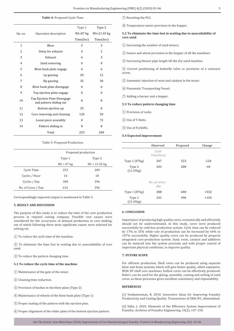
After implementing above suggestions, expected time is given in Table 4.
5Frontiers in Manufacturing Engineering (FME) 4(2) (2020) 01-06
Cite The Article: Arun Bhiva Rane (2020). Improvement of Core Manufacturing in Foundry. Frontiers in Manufacturing Engineering, 4(2) : 01-06.
⑦ Resetting the PLC.
⑧ Temperature meter provision in the hopper.
5.2 To eliminate the time lost in waiting due to unavailability of core sand
① Increasing the number of sand mixers.
② Sensor and alarm provision in the hopper of all the machines.
③ Increasing blower pipe length till the dry sand machine.
④ Correct positioning of butterfly valve or provision of a conveyor screw.
⑤ Automatic injection of resin and catalyst in the mixer.
⑥ Pneumatic Transporting Vessel.
⑦ Adding a burner and a hopper.
5.3 To reduce pattern changing time
① Provision of racks.
② Use of T-Bolts.
③ Use of Forklifts.
5.4 Expected Improvement
Observed Proposed Change
Cycle Time(Secs)
Type 1 (87kg) 347 223 -124
Type 2 (21.45kg)
243 200 -43
No. of cores/day
Type 1 (87kg) 308 640 +332
Type 2 (21.45kg)
242 396 +154
6. CONCLUSION
Importance of producing high quality cores, economically and efficiently should not be underestimated. In this study, cores were produced successfully by cold-box production system. Cycle time can be reduced by 17% to 35% while rate of production can be increased by 64% to 107% successfully. Higher quality cores can be produced by properly integrated core-production system. Sand, resin, catalyst and additives can be metered into the system precisely and with proper control of important physical conditions, to improve quality.
7. FUTURE SCOPE
For efficient production, Shell cores can be produced using separate blow and drain systems which will give better quality, albeit expensive. With DF shell core machines, hollow cores can be effectively produced. Robo’s can be used for the gluing, assembly, coating and setting of sand cores, as these processes gives excellent consistency and repeatability.
REFERENCES
[1] Venkataraman, R. 2010. Innovative Ideas for Improving Foundry Productivity and Casting Quality. Transactions of 58th IFC, Ahmedabad.
[2] Sitko, J. 2010. Elements of the Efficiency System Improvement of Foundry. Archives of Foundry Engineering, 10(2), 147-150.
Correspondingly expected output is mentioned in Table 5.
5. RESULT AND DISCUSSION
The purpose of this study is to reduce the time of the core production process in reputed casting company. Possible root causes were considered for the occurrence of delayed production in core making, out of which following three most significant causes were selected for solving viz.
① To reduce the cycle time of the machine.
② To eliminate the time lost in waiting due to unavailability of core sand.
③ To reduce the pattern changing time.
5.1 To reduce the cycle time of the machine
① Maintenance of the gate of the mixer.
② Cleaning time reduction.
③ Provision of bushes in the blow plate (Type 2)
④ Maintenance of wheels of the blow bush plate (Type 1)
⑤ Proper mating of the pattern with the ejection pins.
⑥ Proper alignment of the slider plate of the bottom ejection pattern.
Table 4: Proposed Cycle Time.
Op. no. Operation description
Type 1 Type 2
Wt=87 kg Wt=21.45 kg
Time(Sec) Time(Sec)
1 Blow 5 3
2 Delay for exhaust 4 2
3 Exhaust 6 3
4 Sand removing 0 0
5 Blow bush plate engage 6 6
6 Lp gassing 20 12
7 Hp gassing 35 30
8 Blow bush plate disengage 6 6
9 Top ejection plate engage 0 0
10 Top Ejection Plate Disengage and pattern sliding out 8 8
11 Bottom ejection up 35 0
12 Core removing and cleaning 120 50
13 Loose piece assembly 0 72
14 Pattern sliding in 8 8
Total 253 200
Table 5: Proposed Production.
Proposed production
Type 1 Type 2
Wt = 87 kg Wt = 21.45 kg
Cycle Time 253 200
Cycles / Hour 14 18
Cycles / Day 308 396
No. of Cores / Day 616 396
6 Frontiers in Manufacturing Engineering (FME) 4(2) (2020) 01-06
Cite The Article: Arun Bhiva Rane (2020). Improvement of Core Manufacturing in Foundry. Frontiers in Manufacturing Engineering, 4(2) : 01-06.
Research, 28(3), 129-139.
[9] Deore, D.S., Gunjan, B., Chaudhari, A.G., Chaturvedi, S. and Uttam, G. 2015. A Study of Core and Its Types for Casting Process. International Journal of Advanced Technology in Engineering and Science, 3(SI1).
[10] Gupta, A.R., Sanjay, N., Aloni, R.K. and Binzade, H. 2016. A Review on Issues Related to Manual Core Making Process in Foundry Industry. Int. J. for Scientific Research & Development, 3(11).
[11] Kawale, A., Safal, S. and Chetan, C. 2016. Productivity Improvement by Quality Circle: A Case of Foundry. International Journal on Recent and Innovation Trends in Computing and Communication, 4(5), 321 – 330.
[12] Jaiswal, T.P. and Dalu, R.S. 2018. Analysis and Improvement of Productivity by Using Lean Manufacturing Tools in Foundry Industry - A Case Study. International Journal of Innovative Research in Technology, 4(12).
[13] Song, L., Liu, W.H., Li, Y.M. and Xin, F.H. 2019. Humidity-Resistant Inorganic Binder for Sand Core Making in Foundry Practice. Research & Development China foundry, 16(4).
[3] Fayomi, O., Ajayi O. and Popoola. 2011. Suitability of Local Binder Compositional Variation on Silica Sand for Foundry Core-Making. Int. J. of Physical Sciences, 6 (8), 1940-1946.
[4] Fayomi, O., Ajayi, O. and Popoola. 2011. Investigating (Ochadamu) Silica Sand, Clay and Local Oils for Foundry Core. International Journal of the Physical Sciences, 6(8), 1894 -1904.
[5] Fedoryszyn, A., Dańko, J., Dańko, R., Asłanowicz, M., Fulko, T. and Ościłowski, A. 2013. Characteristic of Core Manufacturing Process with Use of Sand, Bonded By Ecological Friendly Nonorganic Binders. Archives of Foundry Engineering published by Foundry Commission of the Polish Academy of Sciences Branch in Katowice, 13(3), 19-24.
[6] Bhimani, D.R., Jayeshkumar, P., Jaydevbhai, J. and Bhavsar. 2013. A Study on Foundry Sand: Opportunities for Sustainable and Economical Concrete. Global Research Analysis, 2(1).
[7] Joshi, A. and Jugulkar, L.M. 2014. Productivity Improvement of Metal Casting Industry. International Journal of Analytical, Experimental and Finite Element Analysis (IJAEFEA), 3(1).
[8] Czerwinski, F., Mir, M. and Kasprzak, W. 2015. Application of Cores and Binders in Metal Casting. International Journal of Cast Metals