FRP STRENGTHENING OF BEAMS AND SLABS 22 STRUCTURE magazine • March 2004 Currently, engineers estimate the crumbling infrastructure of the United States may cost as much as 1.6 trillion dollars to bring the current conditions up to code. What options do modern engineers have? We certainly cannot rebuild everything. The answer may lie in the next evolutionary step in civil engineering materials. Historically, concrete has been the choice medium of some of the most prominent structures. The Romans built the Coliseum and the Americans constructed the Hoover Dam. Ever-changing to meet the growing demands of society, concrete has evolved from the simple concrete of the Romans to the intricate collaborative form of steel and concrete of today. Now, with more structures out growing their design lives and expected live loads, engineers have turned to adding yet another element to reinforced concrete design What are FRP’s? On an elementary level, avoiding an in-depth discussion in micro and macro mechanics, FRP composites are generally composed of one of three different material fibers—carbon, glass, or aramid. These fibers are then grouped, aligning the fibers in a primary uni-directional manner, into bundles defined as a ‘tow’. Once a sufficient number of tows have been manufactured they can then be woven into a fabric. Finally, at the time of application the fabric is saturated with a high-grade epoxy composing the matrix. Please note, however, the above composition description, although similar, only describes an FRP “wet lay- up” system, one of three FRP systems. The remaining two, the pre-peg and pre-cured systems, will be omitted from this article for brevity considerations. The two constituent materials, the material fiber and epoxy matrix combined, form the composite. Unlike more traditional materials, the composite is not homogeneous-isotropic but rather heterogeneous-anisotropic. Translating to the strains and strengths of the composite highly depending on position and orientation. This allows the composite a new efficiency by tailoring the position and orientation of the material thus, optimizing the ultimate capacity. Finally, quite possibly the most defining characteristic of FRP composites is their linear elastic stress-strain relationship. Contrary to steel, the composite experiences no plastic deformation before rupture. As can been seen from Figure 1.1 Stress-strain Relationship (see next page). Therefore, it’s crucial to design the composite to an appropriate strain. When should I consider FRP’s as an alternative? It’s really quite simple. If a structural element, such as a beam or slab, could benefit from additional steel reinforcement acting in tension, then FRP’s could present a strong alternative. This is a useful analogue that may help engineers unfamiliar with composites gain project feasibility. Although an engineer must decide on the type of composite, orientation, and position of the primary fibers, traditional statics still applies. Therefore, once the engineer has identified the existing forces and deficiencies, he/she needs only to apply the composite in a manner that optimizes the primary composite fibers. Typical projects that lend themselves to the inherent advantages of composites include: seismic retrofits, increased dead and live loads, change of use, code compliance, prevention of crack propagation and supplementing loss strength capacity from corroding steel reinforcement. Traditional methods for retrofitting beams and slabs, such as steel plates and shotcrete, should now be considered along with FRP composites. The composites can add needed shear capacity and flexural demands in both positive and negative moment regions. Finally, if you are wishing your beam had originally been constructed with more stirrups, tension, or compression steel, then you should take a close look at an FRP alternative. FRP Composition Carbon Fiber Tow Carbon Fiber Concrete Substrate Carbon Fabric FRP Composite Carbon Fiber Tow Epoxy Matrix FRP Composite Interface Micro mechanics ec ec ec Macro mechanics me me me Structural Application A A A “Band-Aids For Buildings” Zachery I. Smith
Transcript
FRP STRENGTHENING OF BEAMS AND SLABS
22 STRUCTURE magazine • March 2004
Currently, engineers estimate the crumbling infrastructure of the United States may cost as much as 1.6 trillion dollars to bring the current conditions up to code. What options do modern engineers have? We certainly cannot rebuild everything. The answer may lie in the next evolutionary step in civil engineering materials.
Historically, concrete has been the choice medium of some of the most prominent structures. The Romans built the Coliseum and the Americans constructed the Hoover Dam. Ever-changing to meet the growing demands of society, concrete has evolved from the simple concrete of the Romans to the intricate collaborative form of steel and concrete of today. Now, with more structures out growing their design lives and expected live loads, engineers have turned to adding yet another element to reinforced concrete design
What are FRP’s?On an elementary level, avoiding an
in-depth discussion in micro and macro mechanics, FRP composites are generally composed of one of three different material fi bers—carbon, glass, or aramid. These fi bers are then grouped, aligning the fi bers in a primary uni-directional manner, into bundles defi ned as a ‘tow’. Once a suffi cient number of tows have been manufactured they can then be woven into a fabric.
Finally, at the time of application the fabric is saturated with a high-grade epoxy composing the matrix. Please note, however, the above composition description, although similar, only describes an FRP “wet lay-up” system, one of three FRP systems. The remaining two, the pre-peg and pre-cured systems, will be omitted from this article for brevity considerations.
The two constituent materials, the material fi ber and epoxy matrix combined, form the composite. Unlike more traditional materials, the composite is not homogeneous-isotropic but rather heterogeneous-anisotropic. Translating to the strains and strengths of the composite highly depending on position and orientation.
This allows the composite a new effi ciency by tailoring the position and orientation of the material thus, optimizing the ultimate capacity.
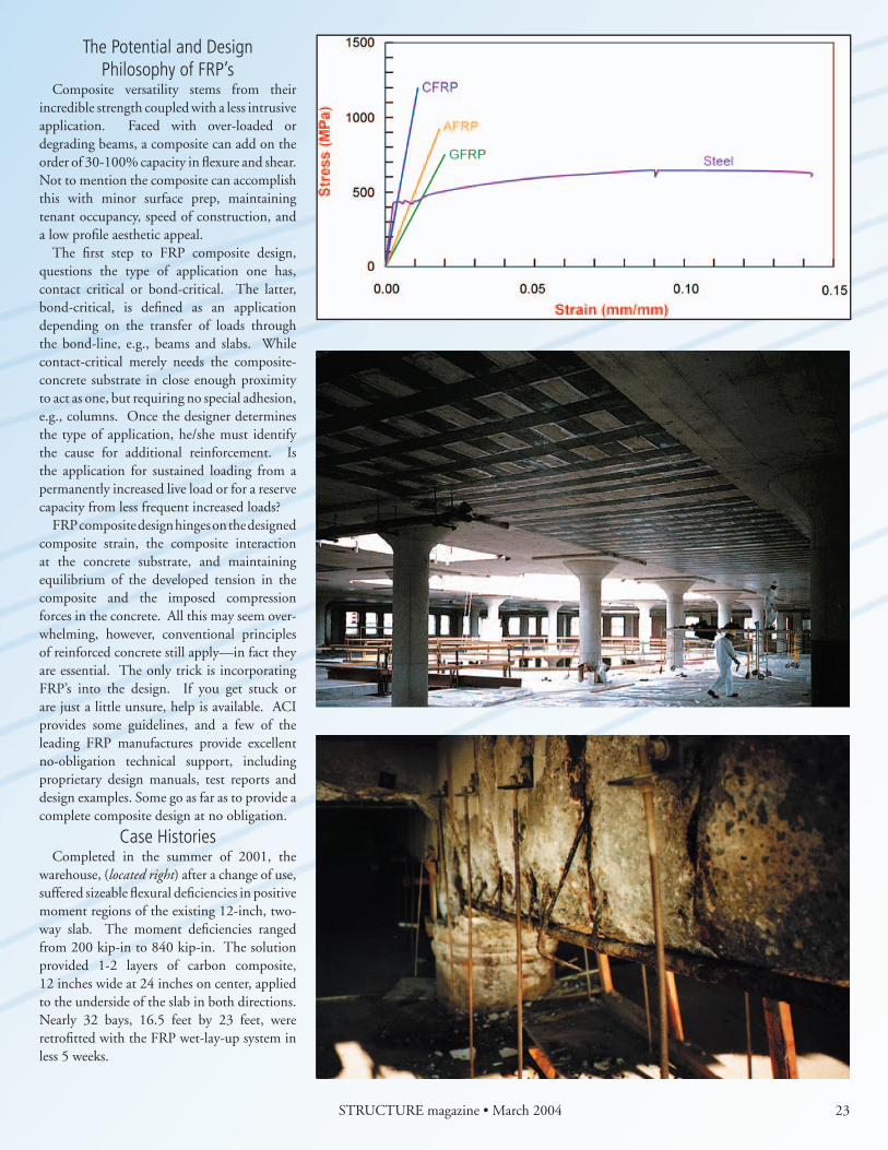
Finally, quite possibly the most defi ning characteristic of FRP composites is their linear elastic stress-strain relationship. Contrary to steel, the composite experiences no plastic deformation before rupture. As can been seen from Figure 1.1 Stress-strain Relationship (see next page). Therefore, it’s crucial to design the composite to an appropriate strain.
When should I considerFRP’s as an alternative?
It’s really quite simple. If a structural element, such as a beam or slab, could benefi t from additional steel reinforcement acting in tension, then FRP’s could present a strong alternative. This is a useful analogue that may help engineers unfamiliar with composites gain project feasibility. Although an engineer must decide on the type of composite, orientation, and position of the primary fi bers,
traditional statics still applies. Therefore, once the engineer has identifi ed the existing forces and defi ciencies, he/she needs only to apply the composite in a manner that optimizes the primary composite fi bers.
Typical projects that lend themselves to the inherent advantages of composites include: seismic retrofi ts, increased dead and live loads, change of use, code compliance, prevention of crack propagation and supplementing loss strength capacity from corroding steel reinforcement. Traditional methods for retrofi tting beams and slabs, such as steel plates and shotcrete, should now be considered along with FRP composites. The composites can add needed shear capacity and fl exural demands in both positive and negative moment regions. Finally, if you are wishing your beam had originally been constructed with more stirrups, tension, or compression steel, then you should take a close look at an FRP alternative.
Composite versatility stems from their incredible strength coupled with a less intrusive application. Faced with over-loaded or degrading beams, a composite can add on the order of 30-100% capacity in fl exure and shear. Not to mention the composite can accomplish this with minor surface prep, maintaining tenant occupancy, speed of construction, and a low profi le aesthetic appeal.
The fi rst step to FRP composite design, questions the type of application one has, contact critical or bond-critical. The latter, bond-critical, is defi ned as an application depending on the transfer of loads through the bond-line, e.g., beams and slabs. While contact-critical merely needs the composite-concrete substrate in close enough proximity to act as one, but requiring no special adhesion, e.g., columns. Once the designer determines the type of application, he/she must identify the cause for additional reinforcement. Is the application for sustained loading from a permanently increased live load or for a reserve capacity from less frequent increased loads?
FRP composite design hinges on the designed composite strain, the composite interaction at the concrete substrate, and maintaining equilibrium of the developed tension in the composite and the imposed compression forces in the concrete. All this may seem over-whelming, however, conventional principles of reinforced concrete still apply—in fact they are essential. The only trick is incorporating FRP’s into the design. If you get stuck or are just a little unsure, help is available. ACI provides some guidelines, and a few of the leading FRP manufactures provide excellent no-obligation technical support, including proprietary design manuals, test reports and design examples. Some go as far as to provide a complete composite design at no obligation.
Case HistoriesCompleted in the summer of 2001, the
warehouse, (located right) after a change of use, suffered sizeable fl exural defi ciencies in positive moment regions of the existing 12-inch, two-way slab. The moment defi ciencies ranged from 200 kip-in to 840 kip-in. The solution provided 1-2 layers of carbon composite, 12 inches wide at 24 inches on center, applied to the underside of the slab in both directions. Nearly 32 bays, 16.5 feet by 23 feet, were retrofi tted with the FRP wet-lay-up system in less 5 weeks.
a common scene with many structures along the coast suffering from sever corrosion and spalling concrete. The supporting girders of the restaurant were estimated to have lost 20% of the steel reinforcement in fl exural and most of the shear stirrups. A certifi ed composite applicator began the project by fi rst chipping away all the loose concrete and then applying a corrosion inhibitor. Following the corrosion inhibitor, the concrete was formed back to its original shape, and then the fi rst layers of composite were applied to the underside of the beam for fl exural reinforcement. Lastly, the application called for composite “U-wraps” to supplement the lost shear stirrups.
to the forefront of structural design. They allow for the preservation of existing structures by maintaining and enhancing serviceability and ultimate limit states. Beam and slab elements now have a retrofi t alternative that can add considerable capacity in both fl exure and shear without severely altering the geometry or global structure. Their complex nature, yet simple application, bring the answers to today’s problems while paving the next chapter in reinforced concrete design.!
Zachery I. Smith graduated fromCal Poly, San Luis Obispo in civil engineering with a concentration in structures. Mr. Smith is currently focusing exclusively in FRP composite design as a project engineer at Fyfe Co. LLC located in San Diego, California.
Typical FRP Projects• Seismic upgrade• Increased dead and/or live loads• Change of use• Corrosion mitigation• Controlling crack propagation


![FIRE PROTECTION SYSTEMS FOR REINFORCED CONCRETE …jcorreia/proj_fct2010_CFRPFire/... · 2011. 2. 16. · FRP-strengthened RC beams [16-19], slabs [20-21] and columns [22] (some of](https://static.documents.pub/doc/80x56/609aa998db449b31be067e67/fire-protection-systems-for-reinforced-concrete-jcorreiaprojfct2010cfrpfire.jpg)


