Use of FTDI devices in life support and/or safety applications is entirely at the user’s risk, and the user agrees to defend, indemnify and hold FTDI harmless from any and all damages, claims, suits
or expense resulting from such use.
Future Technology Devices International Limited (FTDI) Unit 1, 2 Seaward Place, Glasgow G41 1HH, United Kingdom Tel.: +44 (0) 141 429 2777 Fax: + 44 (0) 141 429 2758
This Application Note describes and explains the FT90x UART to GPIO Bridge. The FT90x UART to GPIO Bridge allows the GPIO pins on the FT90x chip to be controlled via commands issued over a UART.
This Application Note describes and explains the FT90x UART to GPIO Bridge. The FT90x UART to GPIO Bridge allows the GPIO pins on the FT90x chip to be controlled via commands issued over a UART.
1.1 Overview
This document describes the design and implementation of the FT90x UART to GPIO Bridge. The FT90x UART to GPIO Bridge allows a user to:
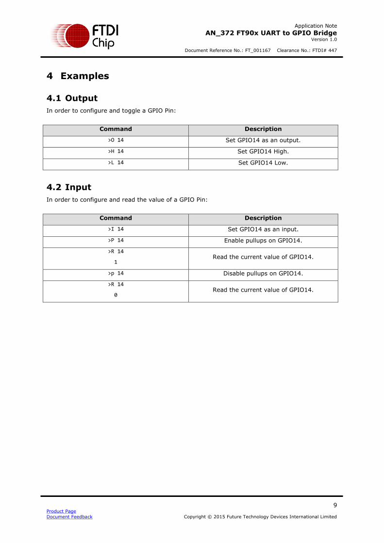
Set up GPIO Pins as Inputs or Outputs. Read the value of a GPIO Pin. Set a GPIO Pin High or Low.
Enable and Disable Pullups.
This document is intended to demonstrate the bridging capabilities of the FT90x family of microcontrollers.
This source code ("the Software") is provided by Future Technology Devices International Limited ("FTDI") subject to the license terms set out http://www.ftdichip.com/FTSourceCodeLicenceTerms.htm ("the License Terms"). You must read the License Terms before downloading or using the Software. By installing or using the Software you agree to the License Terms. If you do not agree to the License Terms then do not download or
use the Software.
Without prejudice to the License Terms, here is a summary of some of the key terms of the License Terms (and in the event of any conflict between this summary and the License Terms then the text of the License Terms will prevail).
The Software is provided "as is". There are no warranties (or similar) in relation to the quality of the Software. You use it at your own risk. The Software should not be used in, or for, any medical device, system or appliance. There are exclusions of FTDI liability for certain types of loss such as:
special loss or damage; incidental loss or damage; indirect or consequential loss or damage; loss of income; loss of business; loss of profits; loss of revenue; loss of contracts; business interruption; loss of the use of money or anticipated savings; loss of information; loss of opportunity; loss of goodwill or reputation; and/or loss of, damage to or corruption of data.
There is a monetary cap on FTDI's liability.
The Software may have subsequently been amended by another user and then distributed by that other user ("Adapted Software"). If so that user may have additional license terms that apply to
those amendments. However, FTDI has no liability in relation to those amendments.
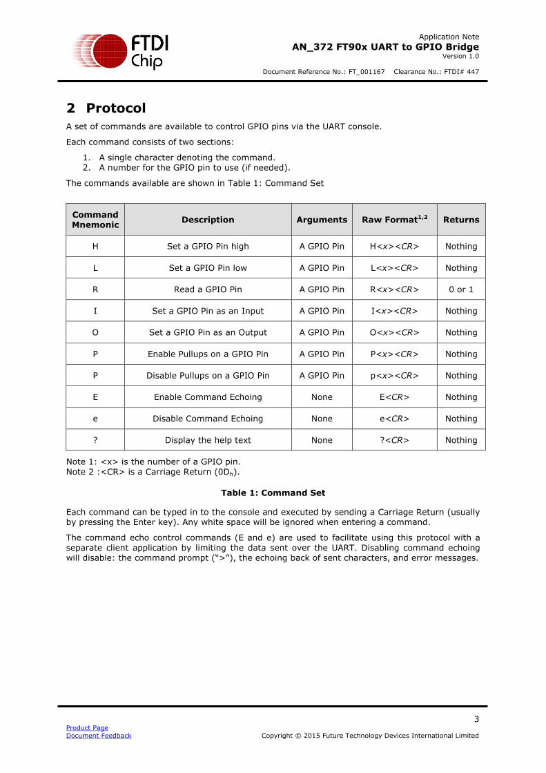
A set of commands are available to control GPIO pins via the UART console.
Each command consists of two sections:
1. A single character denoting the command. 2. A number for the GPIO pin to use (if needed).
The commands available are shown in Table 1: Command Set
Command Mnemonic
Description Arguments Raw Format1,2 Returns
H Set a GPIO Pin high A GPIO Pin H<x><CR> Nothing
L Set a GPIO Pin low A GPIO Pin L<x><CR> Nothing
R Read a GPIO Pin A GPIO Pin R<x><CR> 0 or 1
I Set a GPIO Pin as an Input A GPIO Pin I<x><CR> Nothing
O Set a GPIO Pin as an Output A GPIO Pin O<x><CR> Nothing
P Enable Pullups on a GPIO Pin A GPIO Pin P<x><CR> Nothing
P Disable Pullups on a GPIO Pin A GPIO Pin p<x><CR> Nothing
E Enable Command Echoing None E<CR> Nothing
e Disable Command Echoing None e<CR> Nothing
? Display the help text None ?<CR> Nothing
Note 1: <x> is the number of a GPIO pin.
Note 2 :<CR> is a Carriage Return (0Dh).
Table 1: Command Set
Each command can be typed in to the console and executed by sending a Carriage Return (usually by pressing the Enter key). Any white space will be ignored when entering a command.
The command echo control commands (E and e) are used to facilitate using this protocol with a
separate client application by limiting the data sent over the UART. Disabling command echoing will disable: the command prompt (“>”), the echoing back of sent characters, and error messages.
All the source files for the FT90x firmware are located in the src directory.
3.1 Command Interpreter
The Command Interpreter, contained within shell.c, sets up the UART and manages the reception
and transmission of bytes over the UART.
White space may be inserted between arguments; however, the command interpreter will only buffer a limited number of bytes.
The command interpreter will echo back characters typed to it and will also interpret the DELETE (7Fh) and BACKSPACE (08h) character properly, allowing for the user to use the Backspace key to fix mistakes. The command interpreter will also attempt to ignore any VT100 commands – usually
sent by terminal emulators.
Setup 3.1.1
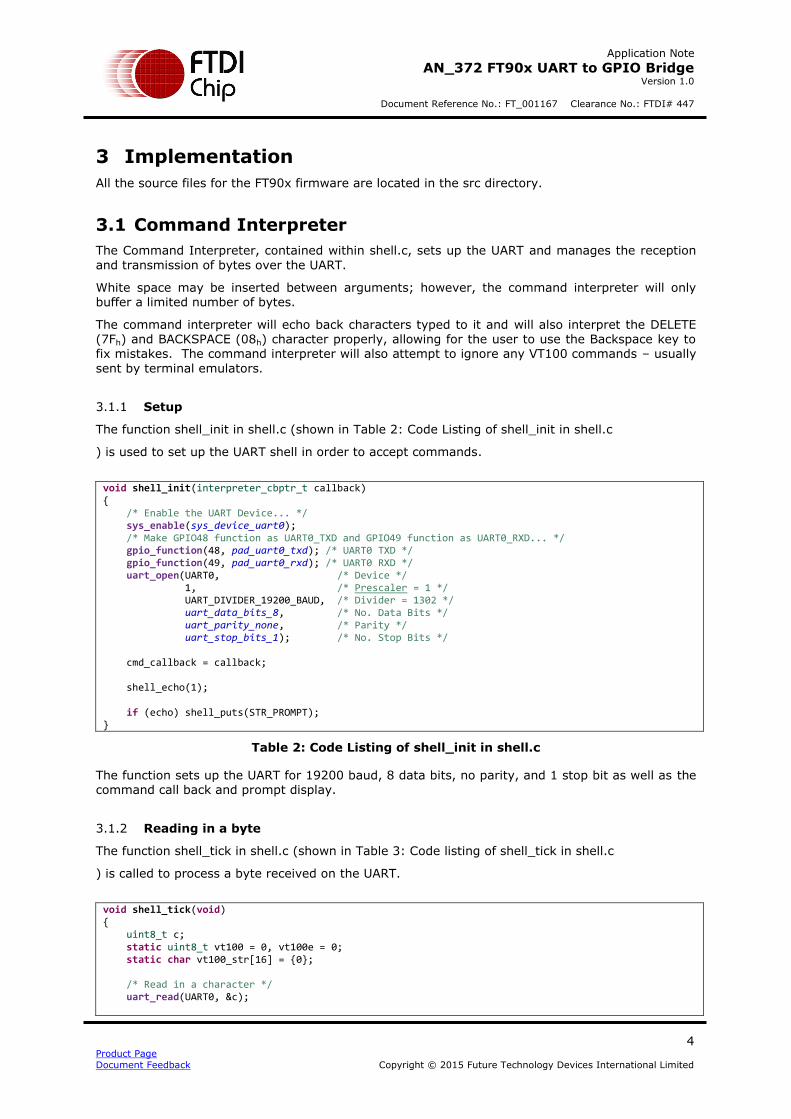
The function shell_init in shell.c (shown in Table 2: Code Listing of shell_init in shell.c
) is used to set up the UART shell in order to accept commands.
void shell_init(interpreter_cbptr_t callback) { /* Enable the UART Device... */ sys_enable(sys_device_uart0); /* Make GPIO48 function as UART0_TXD and GPIO49 function as UART0_RXD... */ gpio_function(48, pad_uart0_txd); /* UART0 TXD */ gpio_function(49, pad_uart0_rxd); /* UART0 RXD */ uart_open(UART0, /* Device */ 1, /* Prescaler = 1 */ UART_DIVIDER_19200_BAUD, /* Divider = 1302 */ uart_data_bits_8, /* No. Data Bits */ uart_parity_none, /* Parity */ uart_stop_bits_1); /* No. Stop Bits */ cmd_callback = callback; shell_echo(1); if (echo) shell_puts(STR_PROMPT); }
Table 2: Code Listing of shell_init in shell.c
The function sets up the UART for 19200 baud, 8 data bits, no parity, and 1 stop bit as well as the command call back and prompt display.
Reading in a byte 3.1.2
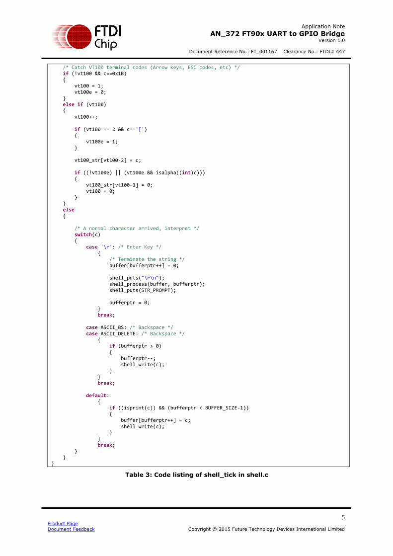
The function shell_tick in shell.c (shown in Table 3: Code listing of shell_tick in shell.c
) is called to process a byte received on the UART.
void shell_tick(void) { uint8_t c; static uint8_t vt100 = 0, vt100e = 0; static char vt100_str[16] = {0}; /* Read in a character */ uart_read(UART0, &c);
In the function, if the character received is the ESCAPE character (1Bh) and the function isn’t currently ignoring a VT100 command, then the ESCAPE character is ignored and the following VT100 command is ignored. If the function is not currently ignoring a command:
If a Carriage Return is received, the input string is terminated and the function shell_process is called (See Section 3.1.3).
If a DELETE or BACKSPACE character is received and we have characters in the buffer, remove one character from the buffer and echo back the character sent.
For all other characters received, if it is printable and space is available to store it, save the character received and echo it back.
Parsing Commands 3.1.3
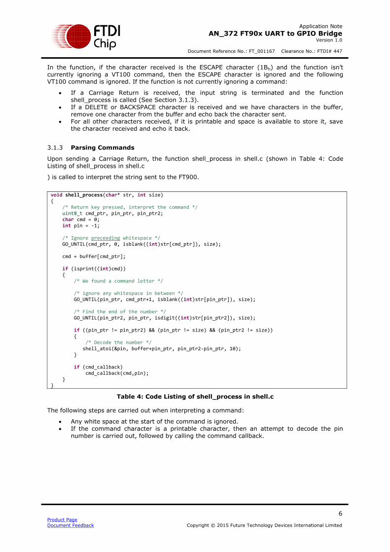
Upon sending a Carriage Return, the function shell_process in shell.c (shown in Table 4: Code
Listing of shell_process in shell.c
) is called to interpret the string sent to the FT900.
void shell_process(char* str, int size) { /* Return key pressed, interpret the command */ uint8_t cmd_ptr, pin_ptr, pin_ptr2; char cmd = 0; int pin = -1; /* Ignore preceeding whitespace */ GO_UNTIL(cmd_ptr, 0, isblank((int)str[cmd_ptr]), size); cmd = buffer[cmd_ptr]; if (isprint((int)cmd)) { /* We found a command letter */ /* ignore any whitespace in between */ GO_UNTIL(pin_ptr, cmd_ptr+1, isblank((int)str[pin_ptr]), size); /* Find the end of the number */ GO_UNTIL(pin_ptr2, pin_ptr, isdigit((int)str[pin_ptr2]), size); if ((pin_ptr != pin_ptr2) && (pin_ptr != size) && (pin_ptr2 != size)) { /* Decode the number */ shell_atoi(&pin, buffer+pin_ptr, pin_ptr2-pin_ptr, 10); } if (cmd_callback) cmd_callback(cmd,pin); } }
Table 4: Code Listing of shell_process in shell.c
The following steps are carried out when interpreting a command:
Any white space at the start of the command is ignored. If the command character is a printable character, then an attempt to decode the pin
number is carried out, followed by calling the command callback.
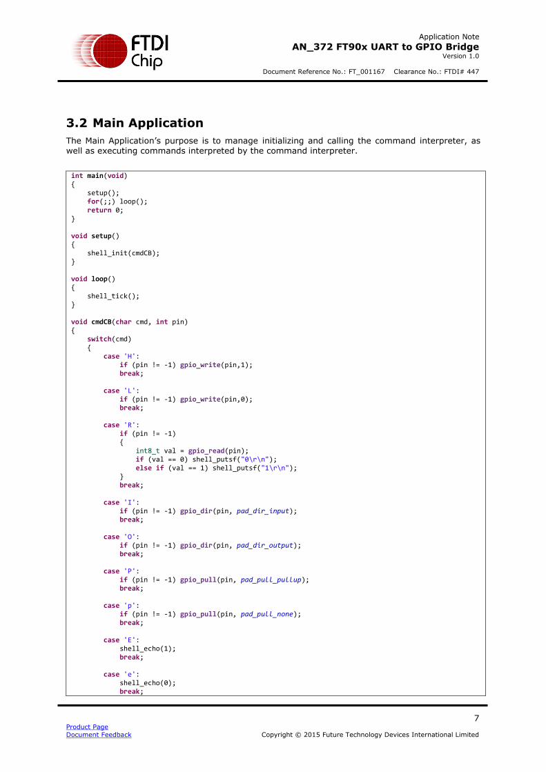
The Main Application’s purpose is to manage initializing and calling the command interpreter, as well as executing commands interpreted by the command interpreter.
int main(void) { setup(); for(;;) loop(); return 0; } void setup() { shell_init(cmdCB); } void loop() { shell_tick(); } void cmdCB(char cmd, int pin) { switch(cmd) { case 'H': if (pin != -1) gpio_write(pin,1); break; case 'L': if (pin != -1) gpio_write(pin,0); break; case 'R': if (pin != -1) { int8_t val = gpio_read(pin); if (val == 0) shell_putsf("0\r\n"); else if (val == 1) shell_putsf("1\r\n"); } break; case 'I': if (pin != -1) gpio_dir(pin, pad_dir_input); break; case 'O': if (pin != -1) gpio_dir(pin, pad_dir_output); break; case 'P': if (pin != -1) gpio_pull(pin, pad_pull_pullup); break; case 'p': if (pin != -1) gpio_pull(pin, pad_pull_none); break; case 'E': shell_echo(1); break; case 'e': shell_echo(0); break;
A Java-based GUI application is provided with this Application Note as an example of how the UART to GPIO Bridge could be used in a more intuitive way. This GUI allows for user to set and control GPIO pins with a mouse.
This application is located within ui/exe with the accompanying source code located at ui/src.
In order to launch the application, double-click on the FT90x_UART_to_GPIO_Bridge.exe Application located within ui/exe.
5.1 Selecting a Serial Port
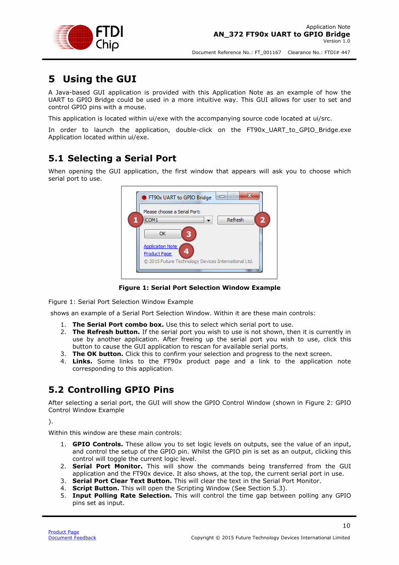
When opening the GUI application, the first window that appears will ask you to choose which serial port to use.
Figure 1: Serial Port Selection Window Example
Figure 1: Serial Port Selection Window Example
shows an example of a Serial Port Selection Window. Within it are these main controls:
1. The Serial Port combo box. Use this to select which serial port to use. 2. The Refresh button. If the serial port you wish to use is not shown, then it is currently in
use by another application. After freeing up the serial port you wish to use, click this button to cause the GUI application to rescan for available serial ports.
3. The OK button. Click this to confirm your selection and progress to the next screen.
4. Links. Some links to the FT90x product page and a link to the application note corresponding to this application.
5.2 Controlling GPIO Pins
After selecting a serial port, the GUI will show the GPIO Control Window (shown in Figure 2: GPIO Control Window Example
).
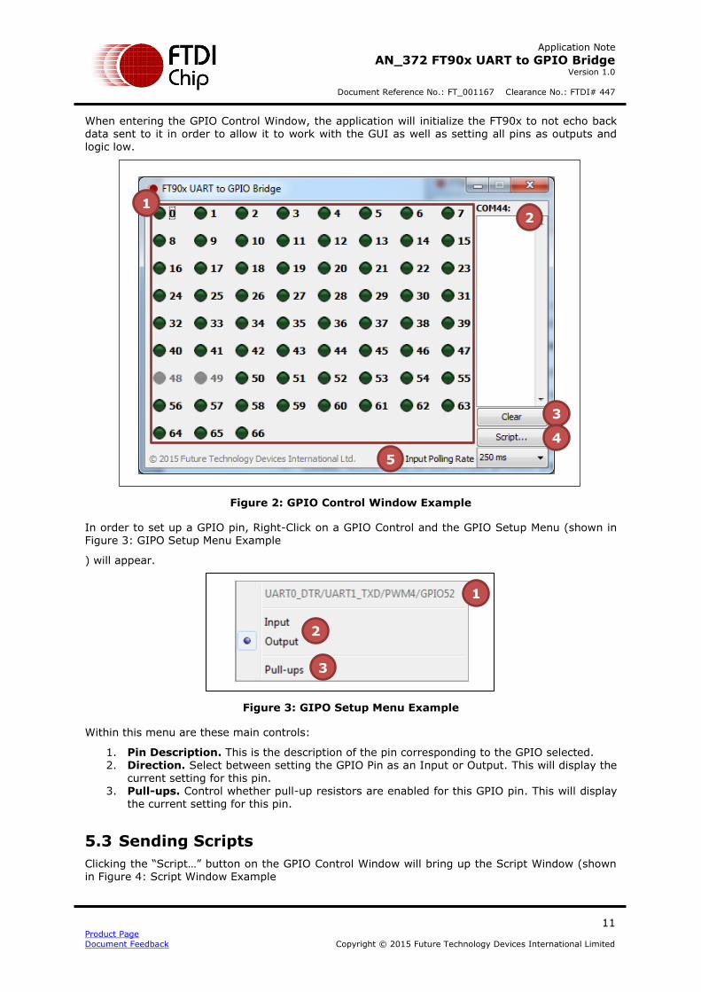
Within this window are these main controls:
1. GPIO Controls. These allow you to set logic levels on outputs, see the value of an input, and control the setup of the GPIO pin. Whilst the GPIO pin is set as an output, clicking this control will toggle the current logic level.
2. Serial Port Monitor. This will show the commands being transferred from the GUI application and the FT90x device. It also shows, at the top, the current serial port in use.
3. Serial Port Clear Text Button. This will clear the text in the Serial Port Monitor. 4. Script Button. This will open the Scripting Window (See Section 5.3). 5. Input Polling Rate Selection. This will control the time gap between polling any GPIO
When entering the GPIO Control Window, the application will initialize the FT90x to not echo back data sent to it in order to allow it to work with the GUI as well as setting all pins as outputs and logic low.
Figure 2: GPIO Control Window Example
In order to set up a GPIO pin, Right-Click on a GPIO Control and the GPIO Setup Menu (shown in Figure 3: GIPO Setup Menu Example
) will appear.
Figure 3: GIPO Setup Menu Example
Within this menu are these main controls:
1. Pin Description. This is the description of the pin corresponding to the GPIO selected. 2. Direction. Select between setting the GPIO Pin as an Input or Output. This will display the
current setting for this pin. 3. Pull-ups. Control whether pull-up resistors are enabled for this GPIO pin. This will display
the current setting for this pin.
5.3 Sending Scripts
Clicking the “Script…” button on the GPIO Control Window will bring up the Script Window (shown in Figure 4: Script Window Example
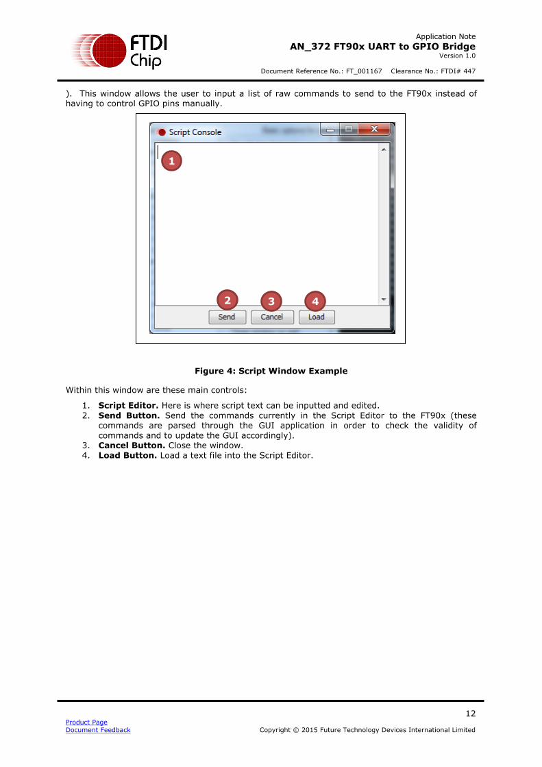
). This window allows the user to input a list of raw commands to send to the FT90x instead of having to control GPIO pins manually.
Figure 4: Script Window Example
Within this window are these main controls:
1. Script Editor. Here is where script text can be inputted and edited.
2. Send Button. Send the commands currently in the Script Editor to the FT90x (these commands are parsed through the GUI application in order to check the validity of
commands and to update the GUI accordingly). 3. Cancel Button. Close the window. 4. Load Button. Load a text file into the Script Editor.
Please visit the Sales Network page of the FTDI Web site for the contact details of our distributor(s) and sales representative(s) in your country.
System and equipment manufacturers and designers are responsible to ensure that their systems, and any Future Technology
Devices International Ltd (FTDI) devices incorporated in their systems, meet all applicable safety, regulatory and system-level
performance requirements. All application-related information in this document (including application descriptions, suggested
FTDI devices and other materials) is provided for reference only. While FTDI has taken care to assure it is accurate, this information is subject to customer confirmation, and FTDI disclaims all liability for system designs and for any applications
assistance provided by FTDI. Use of FTDI devices in life support and/or safety applications is entirely at the user’s risk, and the
user agrees to defend, indemnify and hold harmless FTDI from any and all damages, claims, suits or expense resulting from
such use. This document is subject to change without notice. No freedom to use patents or other intellectual property rights is
implied by the publication of this document. Neither the whole nor any part of the information contained in, or the product
described in this document, may be adapted or reproduced in any material or electronic form without the prior written consent
of the copyright holder. Future Technology Devices International Ltd, Unit 1, 2 Seaward Place, Centurion Business Park,
Glasgow G41 1HH, United Kingdom. Scotland Registered Company Number: SC136640


![SW Tools Solutions for DA8x - processors.wiki.ti.com€¦ · UART UART MMC/SD [at GA] ERTFS [at GA] Linux Drivers GPIO McASP GPIO McASP I2C I2C LCDC SPI SPI USB UART UART NAND EMAC](https://static.documents.pub/doc/80x56/5ed87c1486e3a10d342b8b79/sw-tools-solutions-for-da8x-uart-uart-mmcsd-at-ga-ertfs-at-ga-linux-drivers.jpg)


