Use of Bridgetek devices in life support and/or safety applications is entirely at the user’s risk, and the user agrees to defend, indemnify and hold Bridgetek harmless from any and all damages,
This Application Note describes a virtual keyboard implemented with an FT9XX device and an FT81X touch screen. The virtual keyboard behaves as a standard hardware keyboard when connected via USB to a host computer.
This Application Note describes a virtual keyboard implemented with an FT9XX device and an FT81X touch screen. The virtual keyboard behaves as a standard hardware keyboard when connected via USB to a host computer. The keyboard can be set to show different keyboard layouts for different regional variations.
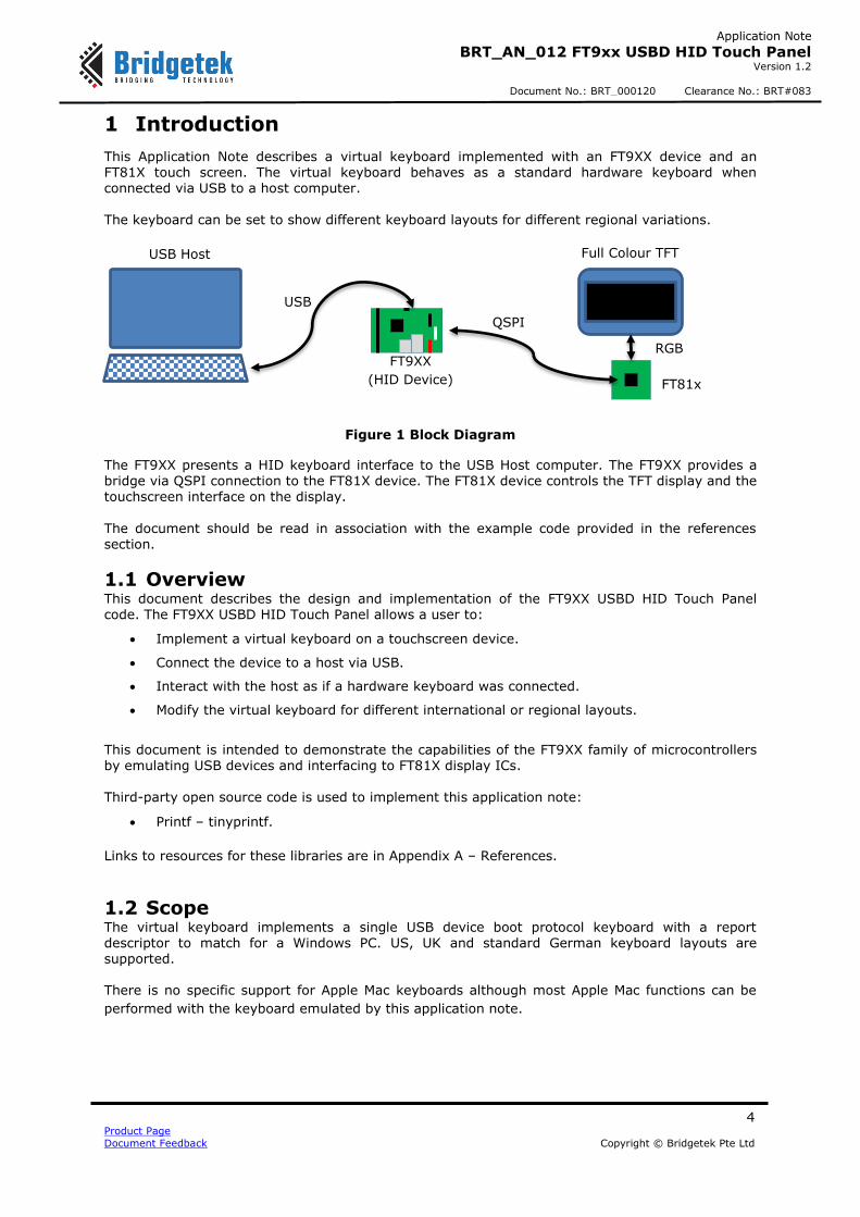
Figure 1 Block Diagram
The FT9XX presents a HID keyboard interface to the USB Host computer. The FT9XX provides a bridge via QSPI connection to the FT81X device. The FT81X device controls the TFT display and the touchscreen interface on the display.
The document should be read in association with the example code provided in the references section.
1.1 Overview This document describes the design and implementation of the FT9XX USBD HID Touch Panel code. The FT9XX USBD HID Touch Panel allows a user to:
Implement a virtual keyboard on a touchscreen device.
Connect the device to a host via USB.
Interact with the host as if a hardware keyboard was connected.
Modify the virtual keyboard for different international or regional layouts.
This document is intended to demonstrate the capabilities of the FT9XX family of microcontrollers by emulating USB devices and interfacing to FT81X display ICs. Third-party open source code is used to implement this application note:
Printf – tinyprintf.
Links to resources for these libraries are in Appendix A – References.
1.2 Scope The virtual keyboard implements a single USB device boot protocol keyboard with a report descriptor to match for a Windows PC. US, UK and standard German keyboard layouts are supported. There is no specific support for Apple Mac keyboards although most Apple Mac functions can be
performed with the keyboard emulated by this application note.
The application note shows how to implement a USB HID device and interface with an FT81X family display IC.
The USB device interface is used to send keyboard scan codes to the host and receive reports to change the status of the Caps Lock, Scroll Lock and Num Lock LEDs on the keyboard. The FT81X interface shows communication with the display IC co-processor, reading touch events and processing these to generate the keyboard scan codes. The display has several screens that can be selected with buttons to allow different layout or part of a keyboard to be displayed.
1.2.2 Possible Enhancements
This application note can be seen as a start for customisation or extension. Some example enhancements could be:
- Support for other country keyboard layouts.
- Add an Apple Mac layout.
- Tailor keyboard layout and function to a particular application. E.g. CAD or Point of Sale.
- Add a multimedia control interface.
- Implementing remote wakeup to allow the keyboard to wake the host.
The project files for the application are divided into the following folders.
Folder Description
Source Application source code and abstraction files.
Includes Application specific header files.
Images JPEG images for this application.
Fonts Font data for this application.
FontConvertor EVE Font Convertor output files for this application.
lib Library files.
lib\eve EVE API libraries.
lib\eve_ui EVE User Interface API libraries.
lib\tinyprintf tinyprintf library.
Table 1 - Project Files Overview
2.1 Sources Folder The main part of the application is found in the “Sources” folder. This is split into 2 sections and
has 2 source code files.
- The “main.c” file is generally responsible for the FT9xx setup and USB device code. - The second file “keyboard.c” implements an interface between the USB device and the
FT81x display.
The other file in this folder is:
- “crt0.S” a modified start-up file (in FT9xx assembly language) to allow the application to write to a protected section of FlashROM on the device.
Files in these folders use the “Includes” folder for application specific header files.
2.2 eve Folder This folder holds the FT81x API code which abstracts the FT81X register and processing list writes into C functions. The API code is similar to the code used in FT81X BRT_AN_025 Application Note.
2.3 eve_ui Folder The eve_ui library presents the keyboard interface to the user by sending display lists to the FT81X via the eve library. The library includes custom fonts and images for the virtual keyboard as well as the code for generating the virtual keyboard display lists.
- The “eve_ui_main.c” file performs general FT81X operations such as initialisation,
calibration and detecting touchscreen events (tags). It will also generate some simple display lists for “Waiting for Host” and an optional screenshot feature.
- The next file “eve_ui_keyboard.c” is responsible for displaying the virtual keyboard, keypad, settings screen and any application-specific extensions required. It will make display lists for each type of keyboard and populate tag information for the touchscreen
- “eve_ui_images.c” contains code for loading JPG images from Program Memory of the FT9XX to the data memory of the FT81X.
- “eve_ui_ext_font.c” which has code to load a custom font extension used by this
application to display characters not supported by the built-in fonts on the FT81X.
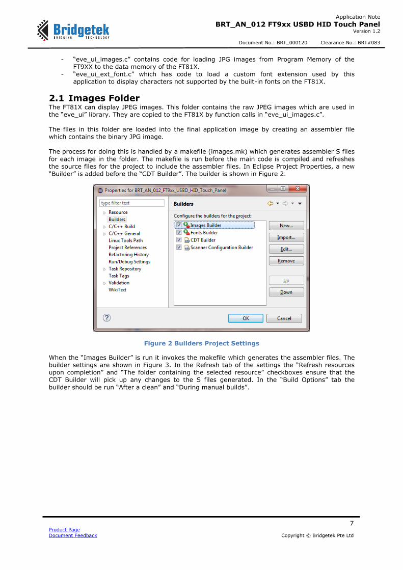
2.1 Images Folder The FT81X can display JPEG images. This folder contains the raw JPEG images which are used in the “eve_ui” library. They are copied to the FT81X by function calls in “eve_ui_images.c”. The files in this folder are loaded into the final application image by creating an assembler file which contains the binary JPG image. The process for doing this is handled by a makefile (images.mk) which generates assembler S files
for each image in the folder. The makefile is run before the main code is compiled and refreshes the source files for the project to include the assembler files. In Eclipse Project Properties, a new “Builder” is added before the “CDT Builder”. The builder is shown in Figure 2.
Figure 2 Builders Project Settings
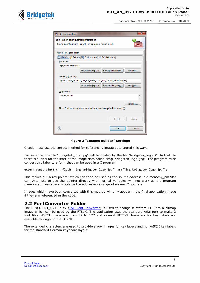
When the “Images Builder” is run it invokes the makefile which generates the assembler files. The builder settings are shown in Figure 3. In the Refresh tab of the settings the “Refresh resources upon completion” and “The folder containing the selected resource” checkboxes ensure that the CDT Builder will pick up any changes to the S files generated. In the “Build Options” tab the
builder should be run “After a clean” and “During manual builds”.
C code must use the correct method for referencing image data stored this way.
For instance, the file “bridgetek_logo.jpg” will be loaded by the file “bridgetek_logo.S”. In that file
there is a label for the start of the image data called “img_bridgetek_logo_jpg”. The program must convert this label to a form that can be used in a C program: extern const uint8_t __flash__ img_bridgetek_logo_jpg[] asm("img_bridgetek_logo_jpg");
This makes a C array pointer which can then be used as the source address in a memcpy_pm2dat call. Attempts to use the pointer directly with normal variables will not work as the program memory address space is outside the addressable range of normal C pointers. Images which have been converted with this method will only appear in the final application image if they are referenced in the code.
2.2 FontConvertor Folder The FT8XX FNT_CVT utility (EVE Font Converter) is used to change a system TTF into a bitmap
image which can be used by the FT81X. The application uses the standard Arial font to make 2
font files: ASCII characters from 32 to 127 and several UETF-8 characters for key labels not available through normal ASCII. The extended characters are used to provide arrow images for key labels and non-ASCII key labels for the standard German keyboard layout.
2.3 Fonts Folder The font files in this folder are the .rawh files produced by the FontConvertor. They are loaded into the final application image by creating a C file which contains the binary font data in the form of an array. The process for doing this is handled by a makefile (fonts.mk) which generates C files for each font
file in the folder. The makefile is run before the main code is compiled and refreshes the source files for the project. In Eclipse Project Properties, a new “Builder” is added before the “CDT Builder”. The builder is called “Fonts Builder” and is shown in Figure 2. Builder settings are the same as for the Images Builder.
The application note implements a USB HID class device which can be accessed by a USB host with appropriate driver software. The USB device code is implemented in main.c and USB HID class specific code is in keyboard.c. All virtual keyboard drawing is carried out in the eve_ui library which invokes the eve library for low-level control of the FT81X device. Keypress events detected on the virtual keyboard will generate “tags” which uniquely represent
one keyboard action. These tags indicate that a key has been pressed, such as a letter or number key. Each tag received will be converted into a HID report and sent to the host via USB.
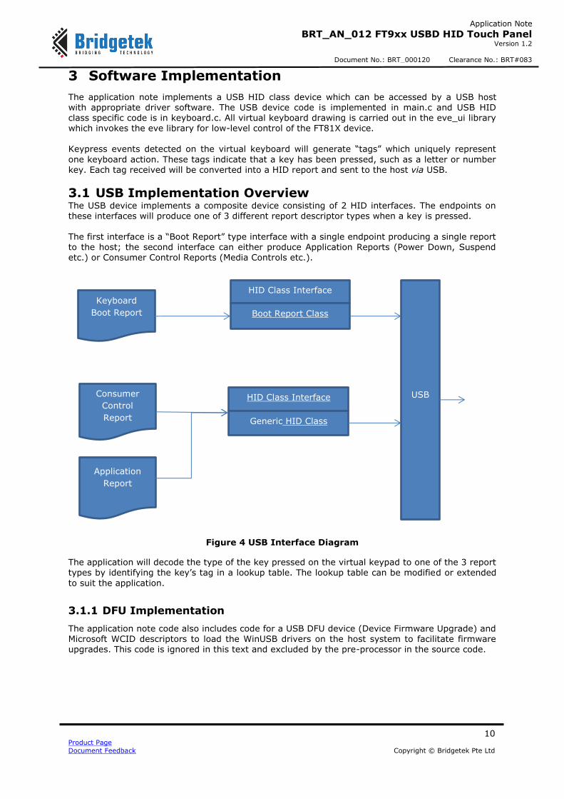
3.1 USB Implementation Overview The USB device implements a composite device consisting of 2 HID interfaces. The endpoints on these interfaces will produce one of 3 different report descriptor types when a key is pressed. The first interface is a “Boot Report” type interface with a single endpoint producing a single report to the host; the second interface can either produce Application Reports (Power Down, Suspend
etc.) or Consumer Control Reports (Media Controls etc.).
Figure 4 USB Interface Diagram
The application will decode the type of the key pressed on the virtual keypad to one of the 3 report types by identifying the key’s tag in a lookup table. The lookup table can be modified or extended
to suit the application.
3.1.1 DFU Implementation
The application note code also includes code for a USB DFU device (Device Firmware Upgrade) and Microsoft WCID descriptors to load the WinUSB drivers on the host system to facilitate firmware upgrades. This code is ignored in this text and excluded by the pre-processor in the source code.
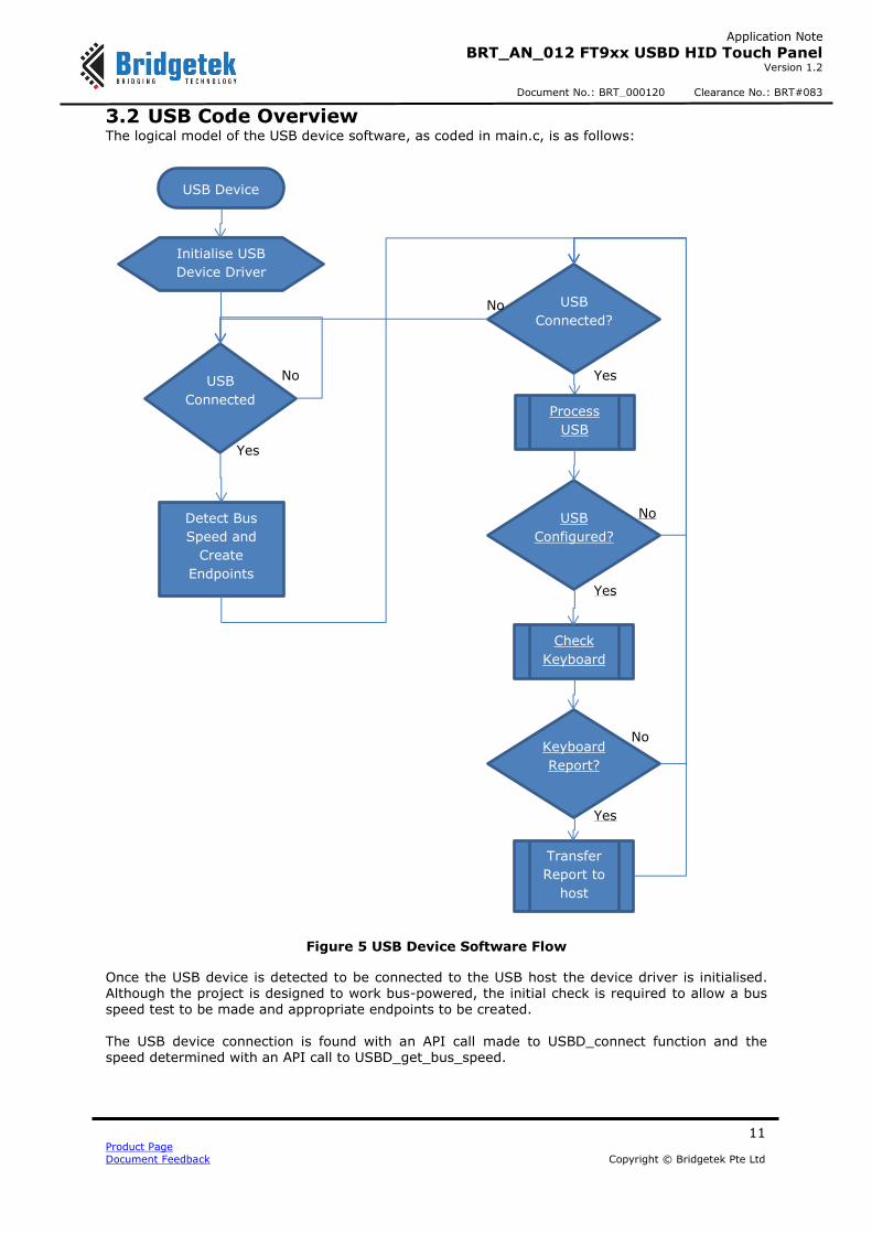
3.2 USB Code Overview The logical model of the USB device software, as coded in main.c, is as follows:
Figure 5 USB Device Software Flow
Once the USB device is detected to be connected to the USB host the device driver is initialised. Although the project is designed to work bus-powered, the initial check is required to allow a bus speed test to be made and appropriate endpoints to be created. The USB device connection is found with an API call made to USBD_connect function and the speed determined with an API call to USBD_get_bus_speed.
Once initialised, the software will continue to check for a proper connection to the host. If this drops then it will return to the state of waiting for a connection. If the device is not bus-powered then it will re-detect the host and bus speed.
The API call to USB_process will update the USB device state and handle any control endpoint requests from the host. When starting the device this will primarily be enumeration requests and result in the USB device state moving from ATTACHED to POWERED, then to DEFAULT and then to ADDRESSED. At this point the USB host can address non-control endpoints on the device. Finally, once the device driver on the host completes initialisation it will move to CONFIGURED state. These states are defined, explained and discussed in the USB Specification.
The USB device in this code waits for the CONFIGURED state to be reached before checking for reports to send to the host.
3.2.1 USB Descriptors
All descriptors which are used in responses to standard USB SETUP requests are placed in main.c.
- The Device Descriptor - 2 Configuration Descriptors, High-speed and Full-speed - A Device Qualifier Descriptor - String Descriptors - 2 HID Report Descriptors
A standard request USB Other Speed Configuration Descriptor is generated using the data from
the Configuration Descriptors.
3.2.2 USB Control Endpoint Requests
USB requests are handled by the USB device driver when the USBD_process API call is made. This will invoke callback functions in main.c to process standard USB requests for descriptors and state changing, but will also receive Class and Vendor requests.
Class requests are received in the class_req_cb function and are decoded to call the
class_req_interface_hid function if this is required. This class-specific function deals with interface requests to the HID device. It will process the Get/Set Idle, Get /Set Protocol and Get/Set Report requests. These handlers may call the keyboard interface code to retrieve or set states.
3.3 Keyboard Code Overview The keyboard interface code keeps an internal state of the HID class device, treating the 2 HID class interfaces separately. The state of a HID interface is affected by the SetIdle request and the SetProtocol request. The
enable state of the Boot Report keyboard (whether it transmits data to the host on its Interrupt IN endpoint) is set by the reception of a suitable SetIdle request. The generic HID interface is enabled once the device reaches the CONFIGURED state. The keyboard function keyboard_loop is polled and this will receive tags from the virtual keyboard, translate these to reports and return a status indicating whether data needs to be transmitted to the host.
3.3.1 Generating Reports
When a tag is received from the virtual keyboard it will be translated into a HID report by the keyboard code in keyboard.c. Depending on the tag, the HID report will be one of the three defined types. The Generic HID interface on which consumer control and system control reports are sent requires
a report ID to identify the type of the report. This is used by the host to match the report up to a
report descriptor. The Boot Report USB interface has a single report defined and therefore does
not require a report ID. Consumer control and system control reports are normally on-off controls (OOCs) or one-shot
controls (OSCs) as defined in the Universal Serial Bus HID Usage Tables. Modification of the report generation code will be required for other types of Usage Types.
3.3.1.1 Boot Reports
Boot reports contain several flags for ‘modifier’ keys (shift, control, alt and GUI) and one-byte scancodes which identify any ‘normal’ key pressed. If no normal key is pressed then the scancode will be zero. When any key is released then a report is sent with either or both the flag and scancode cleared.
3.3.1.2 Consumer Control Reports
The consumer control report will send a two-byte scancode with the appropriate function for the
tag. The report ID for consumer controls is 2.
3.3.1.3 System Control Reports
A system control report allows for one (or more) of the power down, sleep or wake flags to be set.
The report ID for system controls is 1.
3.4 Virtual Keyboard Code Overview The FT81x device relies on a method called a display list to determine what is shown on the screen. This means that a new display list is generated only when a display change is required.
Each virtual “key” on the keyboard is assigned a unique tag. The function eve_ui_keyboard_loop in eve_ui_keyboard.c source code file detects a touchscreen press and returns the tag of the button.
Some buttons are reserved within the eve_ui library to enable switching between keyboard, keypad, media and special screens. The eve_ui library is designed to isolate the screen drawing and management from the features of the USB keyboard device. This will allow it to be used as data entry method for other applications. Only decoding of eve_ui defined tags to actions (or characters) is needed to add text entry.
The screen header is specifically drawn in eve_ui_main.c to allow for the library to be expanded with additional methods.
3.5 Optional Features
3.5.1 Special Screens
A special screen is demonstrated which has a key layout specific to an application. The application
chosen is Zwift (www.zwift.com) which uses keyboard shortcuts to control a cycling simulation. This screen is selected using the orange ‘Z’ on the header bar.
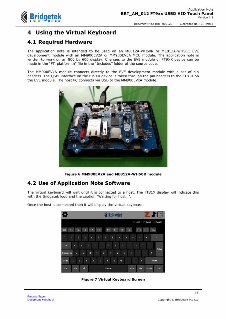
4.1 Required Hardware The application note is intended to be used on an ME812A-WH50R or ME813A-WH50C EVE
development module with an MM900EV2A or MM900EV3A MCU module. The application note is written to work on an 800 by 600 display. Changes to the EVE module or FT9XX device can be made in the “FT_platform.h” file in the “Includes” folder of the source code. The MM900EVxA module connects directly to the EVE development module with a set of pin headers. The QSPI interface on the FT9XX device is taken through the pin headers to the FT81X on
the EVE module. The host PC connects via USB to the MM900EVxA module.
Figure 6 MM900EV2A and ME812A-WH50R module
4.2 Use of Application Note Software
The virtual keyboard will wait until it is connected to a host. The FT81X display will indicate this with the Bridgetek logo and the caption “Waiting for host…”. Once the host is connected then it will display the virtual keyboard.
The settings screen, is accessed from the “Settings” button allowing the choice of UK, US and German keyboard layouts. Pressing “Settings” in the upper left hand corner will display an alphanumeric keyboard section of the virtual keyboard.
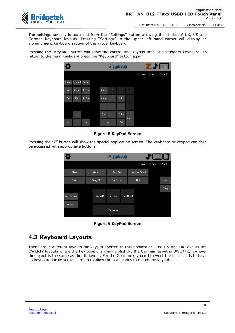
Pressing the “KeyPad” button will show the control and keypad area of a standard keyboard. To return to the main keyboard press the “Keyboard” button again.
Figure 8 KeyPad Screen
Pressing the “Z” button will show the special application screen. The keyboard or keypad can then be accessed with appropriate buttons.
Figure 9 KeyPad Screen
4.3 Keyboard Layouts
There are 3 different layouts for keys supported in this application. The US and UK layouts are QWERTY layouts where the key positions change slightly; the German layout is QWERTZ, however
the layout is the same as the UK layout. For the German keyboard to work the host needs to have its keyboard locale set to German to allow the scan codes to match the key labels.
Please visit the Sales Network page of the Bridgetek Web site for the contact details of our distributor(s) and
sales representative(s) in your country.
System and equipment manufacturers and designers are responsible to ensure that their systems, and any Bridgetek Pte Ltd
(BRTChip) devices incorporated in their systems, meet all applicable safety, regulatory and system-level performance
requirements. All application-related information in this document (including application descriptions, suggested Bridgetek
devices and other materials) is provided for reference only. While Bridgetek has taken care to assure it is accurate, this
information is subject to customer confirmation, and Bridgetek disclaims all liability for system designs and for any applications assistance provided by Bridgetek. Use of Bridgetek devices in life support and/or safety applications is entirely at the user ’s
risk, and the user agrees to defend, indemnify and hold harmless Bridgetek from any and all damages, claims, suits or expense
resulting from such use. This document is subject to change without notice. No freedom to use patents or other intellectual
property rights is implied by the publication of this document. Neither the whole nor any part of the information contained in,
or the product described in this document, may be adapted or reproduced in any material or electronic form without the prior
written consent of the copyright holder. Bridgetek Pte Ltd, 178 Paya Lebar Road, #07-03, Singapore 409030. Singapore