Revision D 9/19/2011 FTE-7500A OTDR Operating Instructions Avoid Exposure Laser Radiation Emitted From Equipment Aperture. This product conforms to CDRH standards for laser product Per 21 CFR 1040.10 & 1040.11
Transcript
Revision D
9/19/2011
FTE-7500A OTDR
Operating Instructions
Avoid Exposure
Laser Radiation Emitted From Equipment Aperture.
This product conforms to CDRH standards for laser product Per 21 CFR 1040.10 & 1040.11
2.0 Loss Test Set Quick Start Guide…..……………………………………….……………………………………………. 2 3.0 Introduction ………………………………………………………………..………………………………………………. 3 4.0 Preparation for Use ………………………………………………………………………………………………………… 4 4.1 Inspection 4.2 Identification / Configuration 4.3 Power Requirements 4.4 Laser Safety
5.0 FTE-7500A Description………………….………………………………………………………………………………….. 5 5.1 Mechanical Enclosure Packaging 5.2 Physical Bottom Panel Top Panel Front Panel 5.3 Display
6.0 Features Description/Operation ……………......……….……………………………………………..………………….. 7 6.1 Battery Level/Power Indicator 6.2 Help 6.3 USB ports USB Flash Port USB PC Port 6.4 Visual Fault Locator 6.5 Loss Test Set 6.6 Video Probe Feature Video Probe port Description/ operation Video Display Video Image Storage Viewing Stored Video Image Adjusting Position of Video Image Adjusting Contrast of Video Image Copy/Delete Video Probe Image 7.0 Tool Menu………….…………………..………………………………………………………………………………………9 7.1 Tool Menu Description 7.2 Accessing the Tool Menu 7.3 Tools Menu Functions Date/Time Resolution Brightness Speaker Power Save
Unit of Measure Cursor Lock Baud Rate Screen Shot Trace Smoothing Set Splice Loss Method and Viewable Measurements Wavelength Filter Pass Code Enter Calibration
I
Revision D
9/19/2011
OTDR Operation 8.0 OTDR Operation ……………………………………………………………………………………………………………. 11 8.1 Key Pad 8.2 Trace Display 8.3 Auto Test Range finder Mode Construction Mode 8.4 Manual Scan Settings Index or Refraction (IOR) Wavelength Average (AVG) Pulse Width Range 8.5 Viewing Trace Zoom Function Zoom Bar Cursor Movement Cursor Lock 8.6 Loss Measurement Definitions Setting Basic Splice Loss Areas Setting Least Squares Approximation (LSA) Splice Loss Measurement Areas 8.7 Unit of Measure 8.8 Quick Save/Recall 8.9 Visual Fault Locator
9.0 Event Analysis ………………………………………………………….………………..………………………………… 16 9.1 Enter/Exit Event Analysis 9.2 Event Table Display 9.3 Table Field Definitions # - Event Number P/F - Pass/Fail KM or KF or MI - Event Location Splice - Event Loss 2 Point - Event to Event Loss DB/KM or KF or MI – Event to Event Loss per Km/Kf/Mi Type – Type of Event E – End of Fiber 9.4 Sensitivity Settings 9.5 Pass/Fail Setting 10.0 File Management ………………………………………………………….………..............……………………………… 20 10.1 Display
10.2 Entering/Exiting File Management 10.3 Saving a Traces 10.4 Renaming Traces 10.5 Viewing Saved Traces 10.6 Dual Trace/Trace Overlay 10.7 Marking Files for Mass Copying or Deleting 10.8 Copying Files 10.9 Deleting Files 10.10 Adding Default Notes
Loss Test Set Operation 11.0 Loss Test Set Description ……………………………………….…………………………………………………… 23 11.1 Entering Loss Test Set Operation Mode 11.2 Key Pad Operation 11.3 LTS Display LTS Measurement Screen LTS File Storage Access Screen LTS Zoom Screen LTS Graph Screen 11.4 Soft Keys Source Power Meter Modulation 11.5 Loss Test Set Icon List Help Delete Quick File Location Tools View Graph Visual Fault Locator Lambda/Wavelength Select
File Download
12.0 Loss Test Set Operation ……………………………………….……………………………………………………… 27 12.1 Power Meter Measurements Power Measurements Relative Measurements 12.2 LTS Autotest Mode 12.3 LTS Light Source Energizing Light Source Modulating Light Source 12.4 LTS File Selector File selector Screen Quick File Locator 12.5 LTS File Transfer 12.6 LTS Graph Mode
13.0 Maintenance ……………………………….……………………….……………………………………………………… 29 13.1 Battery Replacement 13.2 Clock Battery 13.3 Laser Out Port 13.4 Recalibration and Verification 13.6 OTDR Port Adapter Replacement
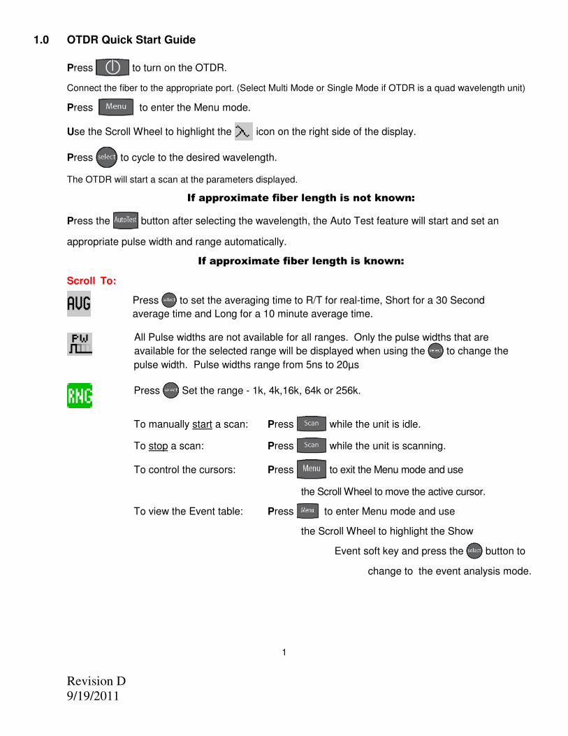
Connect the fiber to the appropriate port. (Select Multi Mode or Single Mode if OTDR is a quad wavelength unit)
Press to enter the Menu mode.
Use the Scroll Wheel to highlight the icon on the right side of the display.
Press to cycle to the desired wavelength.
The OTDR will start a scan at the parameters displayed.
If approximate fiber length is not known:
Press the button after selecting the wavelength, the Auto Test feature will start and set an
appropriate pulse width and range automatically.
If approximate fiber length is known:
Scroll To:
Press to set the averaging time to R/T for real-time, Short for a 30 Second
average time and Long for a 10 minute average time.
All Pulse widths are not available for all ranges. Only the pulse widths that are
available for the selected range will be displayed when using the to change the
pulse width. Pulse widths range from 5ns to 20µs
Press Set the range - 1k, 4k,16k, 64k or 256k.
To manually start a scan: Press while the unit is idle.
To stop a scan: Press while the unit is scanning.
To control the cursors: Press to exit the Menu mode and use
the Scroll Wheel to move the active cursor.
To view the Event table: Press to enter Menu mode and use
the Scroll Wheel to highlight the Show
Event soft key and press the button to
change to the event analysis mode.
1
Revision D
9/19/2011
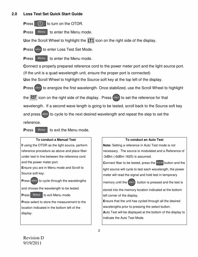
2.0 Loss Test Set Quick Start Guide
Press to turn on the OTDR.
Press to enter the Menu mode.
Use the Scroll Wheel to highlight the icon on the right side of the display.
Press to enter Loss Test Set Mode.
Press to enter the Menu mode.
Connect a properly prepared reference cord to the power meter port and the light source port.
(If the unit is a quad wavelength unit, ensure the proper port is connected)
Use the Scroll Wheel to highlight the Source soft key at the top left of the display.
Press to energize the first wavelength. Once stabilized, use the Scroll Wheel to highlight
the icon on the right side of the display. Press to set the reference for that
wavelength. If a second wave length is going to be tested, scroll back to the Source soft key
and press to cycle to the next desired wavelength and repeat the step to set the
reference.
Press to exit the Menu mode.
2
To conduct an Auto Test
Note: Setting a reference in Auto Test mode is not
necessary. The source is modulated and a Reference of
-3dBm (-6dBm-1625) is assumed.
Connect fiber to be tested, press the button and the
light source will cycle to test each wavelength, the power
meter will read the signal and hold test in temporary
memory until the button is pressed and the test is
stored into the memory location indicated at the bottom
left corner of the display.
Ensure that the unit has cycled through all the desired
wavelengths prior to pressing the select button.
Auto Test will be displayed at the bottom of the display to
indicate the Auto Test Mode.
To conduct a Manual Test
If using the OTDR as the light source, perform
reference procedure as above and place fiber
under test in line between the reference cord
and the power meter port.
Ensure you are in Menu mode and Scroll to
Source soft key.
Press to cycle through the wavelengths
and choose the wavelength to be tested.
Press to exit Menu mode.
Press select to store the measurement to the
location indicated in the bottom left of the
display.
Revision D
9/19/2011
3.0 Introduction
The TTI OTDR is the newest in the line of low cost portable Optical Time Domain Reflectometers with the core functions required to measure optical fiber from one end during installation, repair and verification. The Advanced OTDR is equipped with a 4” TFT color graphic presentation of fiber loss vs. distance, with Dual and Quad Laser sources. The Advanced OTDR is packaged in a rugged aluminum housing which is further protected with a rubberized boot. All controls are accessible via an 7 key weatherproof membrane with a capacitive touch/scroll wheel, offering simple, straightforward functionality.
The TTI OTDR is capable of measuring 2 point loss, splice loss, loss per/km and event ORL. The singlemode and multimode output ports use high power, 850, 1300, 1310, 1490, 1550 or 1625 nm pulsed laser sources. The backscatter receiver uses a temperature compensated avalanche photodiode for reliable, stable performance in fiber links from tens of meters to over 240Km. A high-speed microprocessor, provides the N-point averaging function and control for <1/2 second Real Time update rates. The TTI OTDR is available with an Auto-Wavelength Switching Power Meter. The power meter is calibrated at the 850,1300,1310,1490,1550 and 1625nm, with storage of up to 10,000 power meter tests. The Advanced OTDR software incorporates a feature to supply loss measurement reports and a real-time graph. The color TFT LCD display provides a powerful yet simple set of fiber parameters and control indications to view an entire fiber link or zoom in and analyze a splicing point or defect in the fiber. The display shows all or just the desired loss information. The fiber loss vs. distance in its central graph is large with easily manipulated cursors. The scales are automatically updated for expansion modes and with position changes of the A and B cursors. Individual and dual cursor measurements are displayed as well as important instrument parameters such as Index of Refraction, pulse width, wavelength, range, scanning speed, and a battery gauge. The 7 key panel provides simple straightforward commands to take a scan, make measurements or navigate the soft-key and Icon menus. A new scan is accomplished as easily as pressing the Scan button, within 1/4 second fiber trace data is accessible. To automatically adjust for an unknown fiber length, press the Auto Test button. The soft-key menus are navigated pressing the menu button and scrolling to the soft key bar located at the top of the display. Instrument setup is easily accomplished with the use of the Icon menu located down the right-hand side of the display. The Advanced OTDR also supports the TTI Video Probe and displays a digital image of the connector end face that can be zoomed and centered on the display. The image can also be stored for later review or printed with trace documentation.
3
Revision D
9/19/2011
4.0 Preparation for Use
4.1 Inspection
Before shipment, this instrument has been inspected and found to be in perfect working order and free of defects. The shipping carton contains the following:
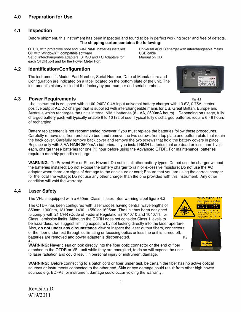
4.2 Identification/Configuration
The instrument’s Model, Part Number, Serial Number, Date of Manufacture and Configuration are indicated on a label located on the bottom plate of the unit. The instrument’s history is filed at the factory by part number and serial number.
4.3 Power Requirements Fig 4.1
The instrument is equipped with a 100-240V-0.4A input universal battery charger with 13.6V, 0.75A, center positive output AC/DC charger that is supplied with interchangeable mains for US, Great Brittan, Europe and Australia which recharges the unit’s internal NiMH batteries (8 - AA, 2500mA hours). Depending on usage, fully charged battery pack will typically enable 8 to 10 hrs of use. Typical fully discharged batteries require 6 - 8 hours of recharging. Battery replacement is not recommended however if you must replace the batteries follow these procedures. Carefully remove unit from protective boot and remove the two screws from top plate and bottom plate that retain the back cover. Carefully remove back cover and remove the two screws that hold the battery covers in place. Replace only with 8 AA NiMH 2500mAh batteries. If you install NiMH batteries that are dead or less than 1 volt each, charge these batteries for one (1) hour before using the Advanced OTDR. For maintenance, batteries require a monthly periodic recharge. WARNING: To Prevent Fire or Shock Hazard: Do not install other battery types; Do not use the charger without the batteries installed; Do not expose the battery charger to rain or excessive moisture; Do not use the AC adapter when there are signs of damage to the enclosure or cord; Ensure that you are using the correct charger for the local line voltage; Do not use any other charger than the one provided with this instrument. Any other condition will void the warranty.
4.4 Laser Safety
The VFL is equipped with a 650nm Class II laser. See warning label figure 4.2
The OTDR has been configured with laser diodes having central wavelengths of 850nm, 1300nm, 1310nm, 1490, 1550 or 1625nm. The unit has been designed to comply with 21 CFR (Code of Federal Regulations) 1040.10 and 1040.11, for Class I emission limits. Although the CDRH does not consider Class 1 levels to be hazardous, we suggest limiting exposure by not looking directly into the laser aperture. Also, do not under any circumstance view or inspect the laser output fibers, connectors or the fiber under test through collimating or focusing optics unless the unit is turned off, batteries are removed and power adapter is disconnected. Fig
4.2
WARNING: Never clean or look directly into the fiber optic connector or the end of fiber attached to the OTDR or VFL unit while they are energized, to do so will expose the user to laser radiation and could result in personal injury or instrument damage. WARNING: Before connecting to a patch cord or fiber under test, be certain the fiber has no active optical sources or instruments connected to the other end. Skin or eye damage could result from other high power sources e.g. EDFAs, or instrument damage could occur voiding the warranty.
4
OTDR, with protective boot and 8-AA NiMH batteries installed Universal AC/DC charger with interchangeable mains CD with Windows™ compatible software USB cable Set of interchangeable adapters, ST/SC and FC Adapters for each OTDR port and for the Power Meter Port
The Advanced OTDR is packaged in a rugged aluminum housing which is further protected with a rubberized boot. Although the front panel is weather resistant, care must be taken to avoid liquids and contaminants around the fragile optical, electrical connectors, and the glass display. Use a mild cleaning agent and damp soft cloth to clean the panels and the outside case. See the maintenance section to clean the optical connector. NEVER open the instrument for cleaning. Return to the factory for servicing if necessary.
Advanced OTDR Packaging The instrument is shipped in a protective cardboard container, universal charger with interchangeable mains, FC/ST and SC interchangeable fiber adapters, USB Cable, and a CD with Windows™ compatible software, and this manual. Save the protective packaging for storage and shipment.
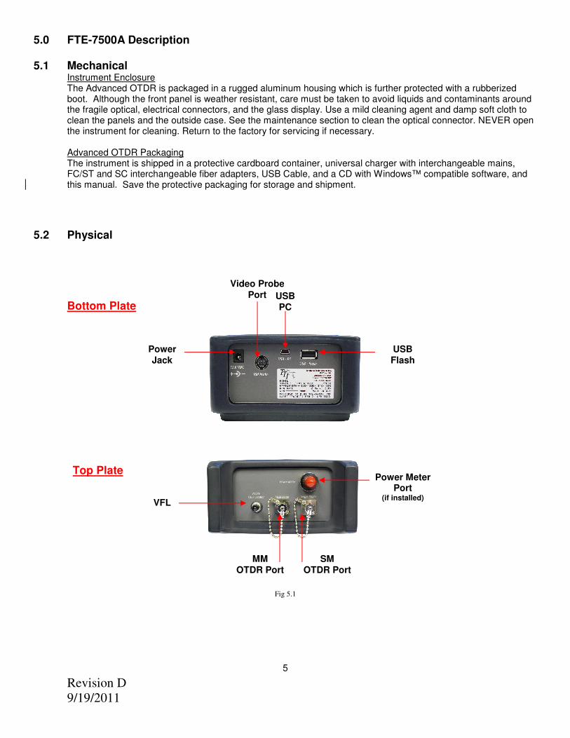
5.2 Physical
Fig 5.1
5
Top Plate
Bottom Plate
VFL
MM OTDR Port
Power Meter Port
(if installed)
SM OTDR Port
USB Flash
Power Jack
Video Probe Port USB
PC
Revision D
9/19/2011
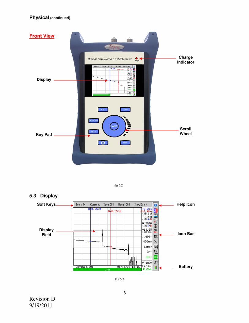
Physical (continued)
Fig 5.2 5.3 Display Fig 5.3
6
Front View
Display
Key Pad
Scroll Wheel
Charge Indicator
Soft Keys Help Icon
Display Field Icon Bar
Battery
Revision D
9/19/2011
6.0 Feature Description/Operation
6.1 Battery Level/Power Indicator
The bottom right hand corner of the screen shows the battery level and charge indicator. In the final hour of operation the battery will change to red. A warning indicator will sound a few minutes before the instrument automatically turns off. Ensure the unit is turned off when plugging in the Battery Charger. When the OTDR is plugged in the AC power, the charge light will be lit (Fig 5.2). The charge light will dim when the batter is fully charged. Also, the battery indicator section on the display (Fig 5.3) will display an AC Plug alongside the battery when operating on AC power.
6.2 Help Feature
The Advanced OTDR has an onboard help feature. To access the help feature, press the Menu button scroll to highlight the Question Mark icon and press the Select button. Scroll to the desired topic and press the Select button. Use the scroll wheel to move down the help page if necessary. Press the Menu button again to exit the help feature.
6.3 USB Ports
USB Flash Drive Located on the bottom panel is the USB Flash Drive port. With the use of a Flash/Thumb drive, traces may be saved directly to an external memory device. Files may also be downloaded to or uploaded from the external memory device. Screen Shots are stored directly to the USB flash drive. Note: Do Not Remove USB Flash Drive While Accessing.
USB/PC Located on the bottom panel is the USB/PC port which is used to connect the OTDR to a computer to download stored data for analysis with the supplied Windows™ compatible software.
6.4 VFL
The Visible Fault Locator (VFL) is a stabilized fiber optic laser source that emits visible (red) light at 650nm. Its intended function is to allow an operator to identify the exact location of a break, micro bend, or other discontinuity in a fiber optic cable. As the radiation is visible, light emanating from a break or micro bend enables the user to locate the exact position of a fault even at very short distances that would not be detectable by other means. It is also useful for identifying a particular fiber in a cable by exciting the fiber to be located with visible radiation. To use the VFL, press the Menu button and scroll to highlight the VFL icon, press the Select button to cycle the VFL through CW (constant wave) mode or modulated mode and Off.
6.5 LTS
The Advanced OTDR with the LTS option incorporates an Auto Wavelength/Auto Test Loss Test Set. Please refer to sections 11 and 12 of this manual for full operating instructions.
6.6 Video Probe Feature
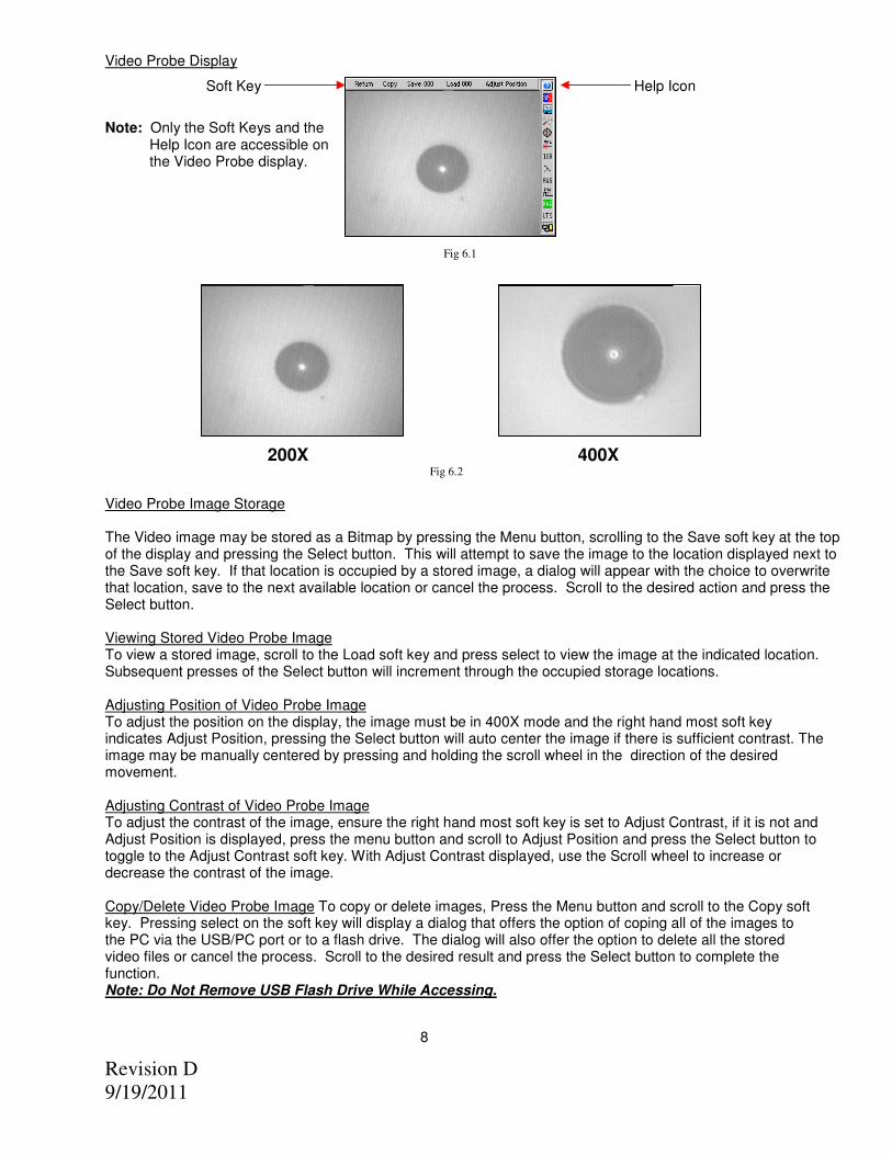
Video Probe Port Description/Operation The Advanced OTDR Version 1.2 or newer can accommodate the TTI Video Probe. Located on the bottom panel is an 8 pin DIN connector labeled “Vid Probe” The OTDR can view a connector end face, center the image and zoom from 200X to 400X. To use this feature; plug in the video probe, press the Menu button and scroll to the Target Icon and press the Select button. Connect to fiber adapters/connectors and focus. For probe operation, see the instructions supplied with the Video Probe. To zoom to 400X, press the Zoom button. Pressing the Zoom button again will revert back to 200x.
7
Revision D
9/19/2011
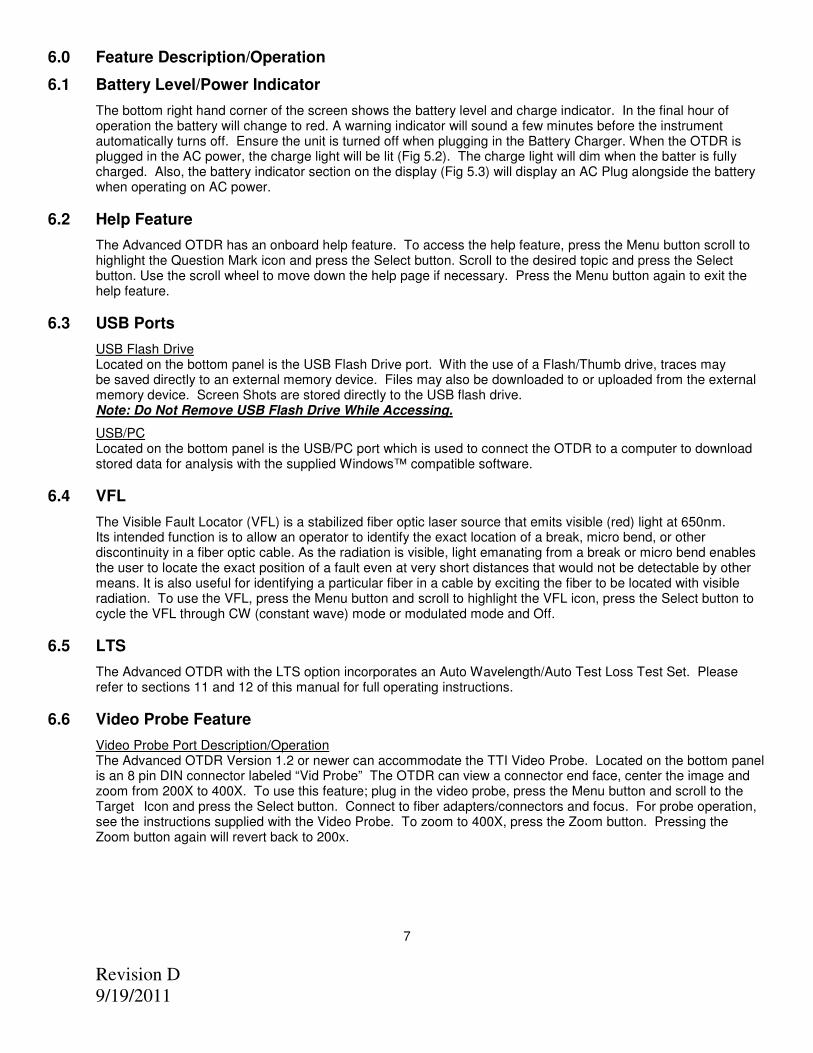
Video Probe Display
Soft Key Help Icon
Note: Only the Soft Keys and the Help Icon are accessible on the Video Probe display.
Fig 6.1
200X 400X Fig 6.2
Video Probe Image Storage
The Video image may be stored as a Bitmap by pressing the Menu button, scrolling to the Save soft key at the top of the display and pressing the Select button. This will attempt to save the image to the location displayed next to the Save soft key. If that location is occupied by a stored image, a dialog will appear with the choice to overwrite that location, save to the next available location or cancel the process. Scroll to the desired action and press the Select button.
Viewing Stored Video Probe Image To view a stored image, scroll to the Load soft key and press select to view the image at the indicated location. Subsequent presses of the Select button will increment through the occupied storage locations. Adjusting Position of Video Probe Image To adjust the position on the display, the image must be in 400X mode and the right hand most soft key indicates Adjust Position, pressing the Select button will auto center the image if there is sufficient contrast. The image may be manually centered by pressing and holding the scroll wheel in the direction of the desired movement. Adjusting Contrast of Video Probe Image To adjust the contrast of the image, ensure the right hand most soft key is set to Adjust Contrast, if it is not and Adjust Position is displayed, press the menu button and scroll to Adjust Position and press the Select button to toggle to the Adjust Contrast soft key. With Adjust Contrast displayed, use the Scroll wheel to increase or decrease the contrast of the image. Copy/Delete Video Probe Image To copy or delete images, Press the Menu button and scroll to the Copy soft key. Pressing select on the soft key will display a dialog that offers the option of coping all of the images to the PC via the USB/PC port or to a flash drive. The dialog will also offer the option to delete all the stored video files or cancel the process. Scroll to the desired result and press the Select button to complete the function. Note: Do Not Remove USB Flash Drive While Accessing.
8
Revision D
9/19/2011
7.0 Tools Menu
7.1 Tools Menu Description
Although many settings for the FTE-7500A are set as the user operates the unit, there are a number of settings that may be made to increase the ease of use for the Advanced OTDR. Many of these settings are located in the Tools menu.
7.2 Accessing the Tools Menu
To access this menu, press the Menu button and use the scroll wheel to highlight the Tools icon. Press the Select button and the Tools Menu will be displayed. Use the scroll wheel to highlight desired function. To exit the Tools Menu, press the Menu button.
7.3 Tools Menu Functions
Date/Time The OTDR applies a time/date stamp to the saved files. The time and date are set at the factory with a MM/DD/YY date and 24 hour format clock. To change the date and time, Highlight the Time/Date tool and press the Select button. A dialog box with the settings will be displayed. Use the scroll wheel to change each segment, use the Select button to move between segments and then to Save/Redo/Cancel. Use the scroll wheel to select Save, Redo or Cancel then press the Select button again to complete the process.
Resolution
At the 4k and 16k ranges the OTDR may be operated in high resolution mode which will increase the resolution to 1/8 of a meter from 1/2 meter at 4k, and to ½ meter from 1 meter at 16k range. To toggle between the two settings, highlight the Resolution icon and use the Select button to toggle between the two settings.
Brightness The Display has a high and low brightness setting. To toggle between the two settings, highlight Brightness tool and use the Select button to toggle between the two settings. Speaker Button press and scroll sounds may be turned on or off as desires. To toggle sound on and off, highlight the Sound tool and use the Select button to switch the sound on and off. Power Save
The Advanced OTDR incorporates a Power save feature that allows for maximum utilization of the battery life. If set to ON, the unit keeps track of the keypad activity and if no key presses are detected for a period of approximately 15 minutes, the unit will automatically turn itself off, storing the current mode settings. To turn the feature on or off, highlight the Power Save tool and press the Select button.
Unit of Measure
To toggle between Kilometer (Km), Kilo feet (Kf), and Mi for mile, press the Select button while the Unit of Measure tool is highlighted.
Cursor Lock:
The OTDR cursors may be locked for accurate measurements. To lock the cursors, scroll to highlight the Cursor Lock tool and press the Select button to toggle the feature on or off. In the lock cursor mode, with the A cursor as the active cursor, both A and B cursors move together and with the B cursor as the active cursor, the B cursor will move independently in order to set the distance between the two cursors.
Baud Rate It may be necessary to set a com port speed for communication with a computer, to set the baud rate, highlight the COM Baud Rate tool, press the Select button and a dialog with the available settings is displayed. Use the scroll wheel to select baud rates from 115k to 921k. Press the Select button again to select the baud rate and close the dialog.
9
Revision D
9/19/2011
Screen Shot The Advanced OTDR is equipped with a Screen Shot tool. This feature will only write files directly to the flash drive. To write a .bmp to the flash drive, highlight the Take a Screenshot tool. Press the Select button, the display will revert to the previous screen and progress will be shown by the inverse color pattern progressing from the bottom to the top of the screen. The process is complete when the display returns to the normal color. The file name will be SShhmmss.bmp, where h = hour, m = minute and s = second. If no flash drive is detected, an error message will be displayed. Note: Do Not Remove USB Flash Drive While Accessing. Note: This method is not used with the Video Probe. The video probe has its own method of saving & copying files.
Trace Smoothing
Note: Smoothing is NOT meant to be used when using the Event Table. Smoothing will smooth the trace for visual interpretation; however, it will cause excess events the event table. Reflective events could be adversely affected in noisy environments.
Smoothing helps reduce noise in a trace to better visually discern events. To set Smoothing levels or to turn Smoothing off, highlight the Trace Smoothing tool, press the Select button and a dialog will be displayed allowing the choice of turning off smoothing or setting it to minimum (Min) or maximum (Max). Use the Scroll Wheel to select desired level and press Select. Smoothing effect is processed after the scan is completed. A minimum scan time of 10 seconds (Short Scan) is required for smoothing to be accomplished. If a long scan is interrupted after 10 seconds the smoothing will be accomplished. Minimum smoothing is instantaneous with a lesser effect. Maximum smoothing requires approximate 1-2 seconds to complete.
Set Viewable Measurements The Advanced OTDR allows the user to set which loss measurements to be displayed. The loss measurements seen are splice loss or Least Squares Approximation (LSA) splice loss for both cursors, dB value between cursors, distance between cursors and dB per Km or Kf. If any of these measurements are not of importance for a series of test, one or more may be turned of for ease of viewing. To accomplish this, highlight View Icon and press Select. A box will be drawn around the splice loss measurements. Use the Scroll wheel to cycle the measurement between LSA Splice, Basic Splice Loss, or off. Press Select to move to the next measurement. The remainder will just toggle between off and on. Continue through the four measurements and the Tools menu will be returned to the screen when select is press on the last measurement.
Wavelength Filter Wavelength Filter allows the user to turn on and off wavelengths as desired for OTDR testing. To accomplish this, highlight Wavelength Filter and press Select. Scrolling to a wavelength and pressing Select will toggle a wavelength off and on. This is useful if the OTDR is a quad and it is only desired to test either SM or MM or if the unit has three wavelengths and only two need to be used for a particular set of test. Pass Code Protection The FTE-7500A may be protected from unauthorized use with a 4 digit pass code. Enter the Tool Menu, scroll to the Pass code Protection tool and press the Select button. Use the Scroll Wheel to set the first digit from 0 to 9 and press Select. Continue until all four positions are entered. Pressing Select on the last digit will move the focus to “Enter” or “Cancel” press Select again set the pass code or use the Scroll Wheel to highlight Cancel and press Select to abandon any changes. Contact TTI technical support if your code is lost, for a master pass code.
Enter Calibration This tool is for factory use.
10
Revision D
9/19/2011
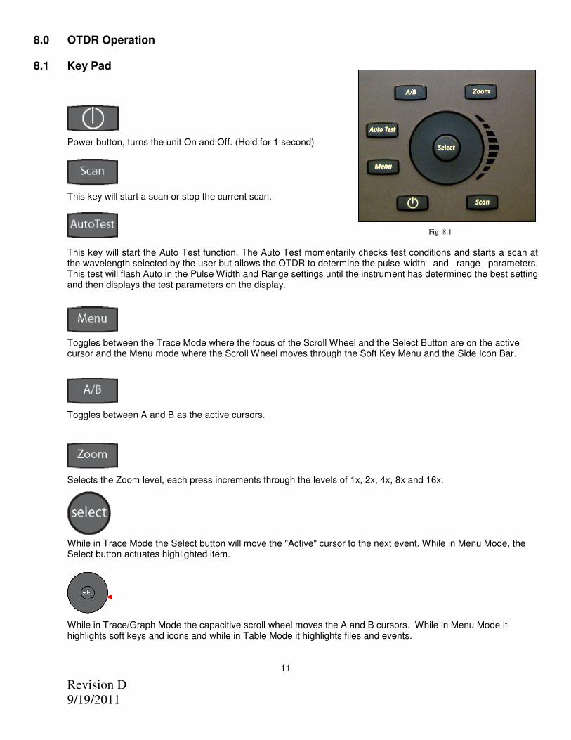
8.0 OTDR Operation 8.1 Key Pad
Power button, turns the unit On and Off. (Hold for 1 second)
This key will start a scan or stop the current scan.
Fig 8.1
This key will start the Auto Test function. The Auto Test momentarily checks test conditions and starts a scan at the wavelength selected by the user but allows the OTDR to determine the pulse width and range parameters. This test will flash Auto in the Pulse Width and Range settings until the instrument has determined the best setting and then displays the test parameters on the display.
Toggles between the Trace Mode where the focus of the Scroll Wheel and the Select Button are on the active cursor and the Menu mode where the Scroll Wheel moves through the Soft Key Menu and the Side Icon Bar.
Toggles between A and B as the active cursors.
Selects the Zoom level, each press increments through the levels of 1x, 2x, 4x, 8x and 16x.
While in Trace Mode the Select button will move the "Active" cursor to the next event. While in Menu Mode, the Select button actuates highlighted item.
While in Trace/Graph Mode the capacitive scroll wheel moves the A and B cursors. While in Menu Mode it highlights soft keys and icons and while in Table Mode it highlights files and events.
11
Revision D
9/19/2011
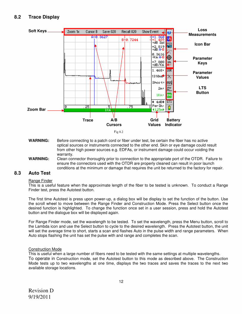
8.2 Trace Display
Fig 8.2 WARNING: Before connecting to a patch cord or fiber under test, be certain the fiber has no active optical sources or instruments connected to the other end. Skin or eye damage could result from other high power sources e.g. EDFAs, or instrument damage could occur voiding the warranty.
WARNING: Clean connector thoroughly prior to connection to the appropriate port of the OTDR. Failure to ensure the connectors used with the OTDR are properly cleaned can result in poor launch conditions at the minimum or damage that requires the unit be returned to the factory for repair.
8.3 Auto Test
Range Finder This is a useful feature when the approximate length of the fiber to be tested is unknown. To conduct a Range Finder test, press the Autotest button. The first time Autotest is press upon power-up, a dialog box will be display to set the function of the button. Use the scroll wheel to move between the Range Finder and Construction Mode. Press the Select button once the desired function is highlighted. To change the function once set in a user session, press and hold the Autotest button and the dialogue box will be displayed again. For Range Finder mode, set the wavelength to be tested. To set the wavelength, press the Menu button, scroll to the Lambda icon and use the Select button to cycle to the desired wavelength. Press the Autotest button, the unit will set the average time to short, starts a scan and flashes Auto in the pulse width and range parameters. When Auto stops flashing the unit has set the pulse with and range and completes the scan.
Construction Mode This is useful when a large number of fibers need to be tested with the same settings at multiple wavelengths.
To operate in Construction mode, set the Autotest button to this mode as described above. The Construction Mode tests up to two wavelengths at one time, displays the two traces and saves the traces to the next two available storage locations.
12
Zoom Bar
Trace A/B Cursors
Grid Values
Battery Indicator
LTS Button
Parameter Values
Loss Measurements
Soft Keys
Icon Bar
Parameter Keys
Revision D
9/19/2011
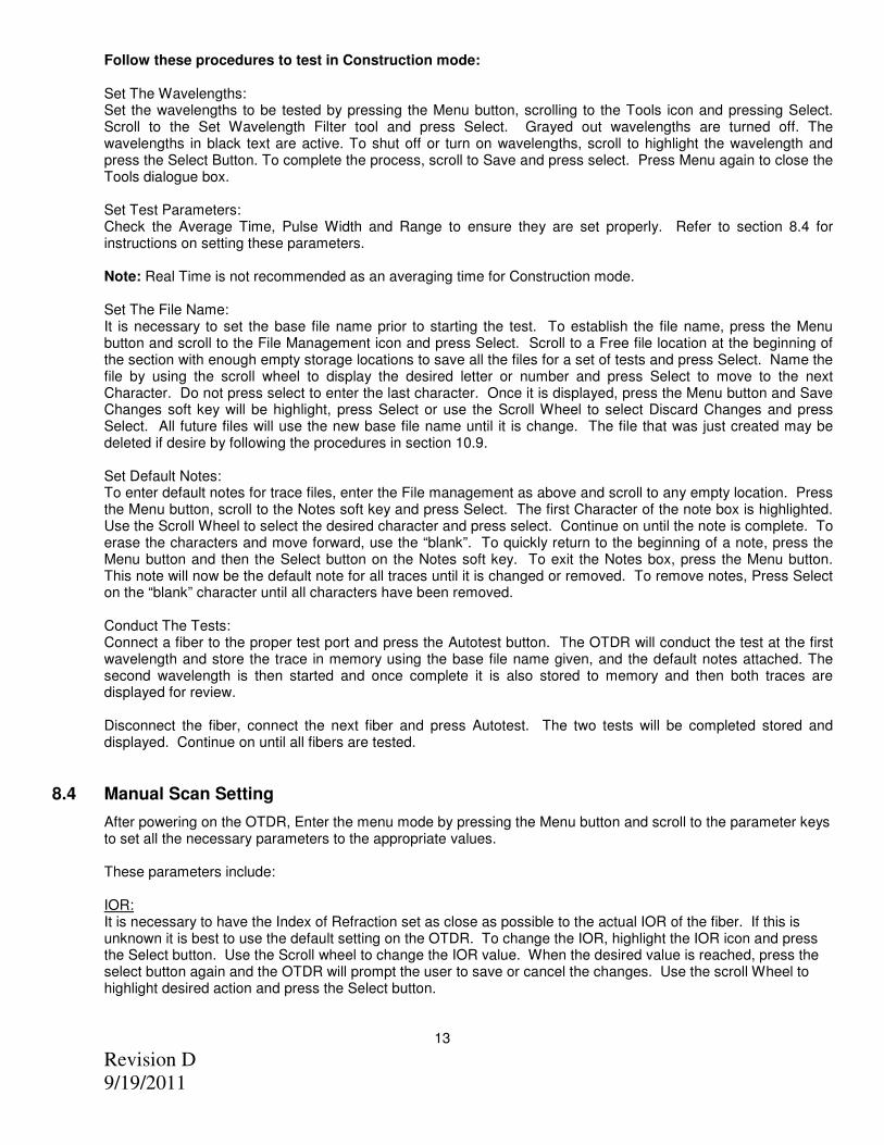
Follow these procedures to test in Construction mode: Set The Wavelengths: Set the wavelengths to be tested by pressing the Menu button, scrolling to the Tools icon and pressing Select. Scroll to the Set Wavelength Filter tool and press Select. Grayed out wavelengths are turned off. The wavelengths in black text are active. To shut off or turn on wavelengths, scroll to highlight the wavelength and press the Select Button. To complete the process, scroll to Save and press select. Press Menu again to close the Tools dialogue box. Set Test Parameters: Check the Average Time, Pulse Width and Range to ensure they are set properly. Refer to section 8.4 for instructions on setting these parameters. Note: Real Time is not recommended as an averaging time for Construction mode. Set The File Name: It is necessary to set the base file name prior to starting the test. To establish the file name, press the Menu button and scroll to the File Management icon and press Select. Scroll to a Free file location at the beginning of the section with enough empty storage locations to save all the files for a set of tests and press Select. Name the file by using the scroll wheel to display the desired letter or number and press Select to move to the next Character. Do not press select to enter the last character. Once it is displayed, press the Menu button and Save Changes soft key will be highlight, press Select or use the Scroll Wheel to select Discard Changes and press Select. All future files will use the new base file name until it is change. The file that was just created may be deleted if desire by following the procedures in section 10.9. Set Default Notes: To enter default notes for trace files, enter the File management as above and scroll to any empty location. Press the Menu button, scroll to the Notes soft key and press Select. The first Character of the note box is highlighted. Use the Scroll Wheel to select the desired character and press select. Continue on until the note is complete. To erase the characters and move forward, use the “blank”. To quickly return to the beginning of a note, press the Menu button and then the Select button on the Notes soft key. To exit the Notes box, press the Menu button. This note will now be the default note for all traces until it is changed or removed. To remove notes, Press Select on the “blank” character until all characters have been removed. Conduct The Tests: Connect a fiber to the proper test port and press the Autotest button. The OTDR will conduct the test at the first wavelength and store the trace in memory using the base file name given, and the default notes attached. The second wavelength is then started and once complete it is also stored to memory and then both traces are displayed for review. Disconnect the fiber, connect the next fiber and press Autotest. The two tests will be completed stored and displayed. Continue on until all fibers are tested.
8.4 Manual Scan Setting
After powering on the OTDR, Enter the menu mode by pressing the Menu button and scroll to the parameter keys to set all the necessary parameters to the appropriate values. These parameters include: IOR:
It is necessary to have the Index of Refraction set as close as possible to the actual IOR of the fiber. If this is unknown it is best to use the default setting on the OTDR. To change the IOR, highlight the IOR icon and press the Select button. Use the Scroll wheel to change the IOR value. When the desired value is reached, press the select button again and the OTDR will prompt the user to save or cancel the changes. Use the scroll Wheel to highlight desired action and press the Select button.
13
Revision D
9/19/2011
Wavelength: Use the scroll wheel to highlight the Lambda key, press select to cycle through the available wavelengths. AVG: Use the scroll wheel to highlight the Average (AVG) icon and use Select button to cycle through, Real-time averaging, with a up to 2 pps refresh rate, Short average (~30 seconds) or long average (~10 minutes). Changing this setting will also initiate a scan.
Pulse Width:
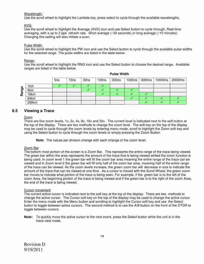
Use the scroll wheel to highlight the PW icon and use the Select button to cycle through the available pulse widths for the selected range. The pulse widths are listed in the table below.
Range:
Use the scroll wheel to highlight the RNG icon and use the Select button to choose the desired range. Available ranges are listed in the table below.
8.5 Viewing a Trace
Zoom There are five zoom levels, 1x, 2x, 4x, 8x, 16x and 32x. The current level is indicated next to the soft button at the top of the display. There are two methods to change the zoom level. The soft key on the top of the display may be used to cycle through the zoom levels by entering menu mode, scroll to highlight the Zoom soft key and using the Select button to cycle through the zoom levels or simply pressing the Zoom Button. Note: The values per division change with each change of the zoom level. Zoom Bar
The bottom most portion of the screen is a Zoom Bar. This represents the entire range of the trace being viewed. The green bar within the area represents the amount of the trace that is being viewed whiled the zoom function is being used. In zoom level 1 the green bar will fill the zoom bar area meaning the entire range of the trace can be viewed and in Zoom level 2 the green bar will fill only half of the zoom bar area, meaning half of the entire range of the trace can be viewed. As the zoom levels increase, the green zoom bar will decrease in size to indicate the amount of the trace that can be viewed at one time. As a cursor is moved with the Scroll Wheel, the green zoom bar moves to indicate what portion of the trace is being seen. For example, if the green bar is to the left of the zoom Area, the beginning portion of the trace is being viewed and if the green bar is to the right of the zoom Area, the end of the trace is being viewed.
Cursor movement The current active cursor is indicated next to the soft key at the top of the display. There are two methods to change the active cursor. The Cursor soft key on the top of the display may be used to change the active cursor. Enter the menu mode with the Menu button and scrolling to highlight the Cursor soft key and use the Select button to toggle between active cursors. The second method is to use the A/B button on the front of the OTDR to toggle between cursors. Note: To quickly move the active cursor to the next event, press the Select button while the unit is in the trace view mode.
Cursor Lock The cursors may be locked for accurate measurements. To lock the cursors press the Menu button, scroll to the Tools icon and press the Select button, scroll to the A/B icon and press Select to toggle the lock cursor mode on and off. In the lock cursor mode, with the A cursor as the active cursor, both A and B cursors move together and with the B cursor as the active cursor, the B cursor will move independently in order to set the distance between the two cursors.
8.6 Loss Measurements
Definitions
• 2 Point loss method takes the difference in vertical height between where the A and B cursors cross the fiber trace to determine loss.
• The dB/Km (dB/Kft) loss method takes the 2 Point loss in dB and divides by the distance between the cursors in Kilometers (Kilo feet). For accurate dB/Km (dB/Kft) loss measurements, the two cursors must be on level backscatter points at least 100m apart (NA will show for distances that are too short).
• Basic Splice Loss method takes the loss around cursor A and B. The averaged areas before and after the splice must be level backscatter, free from defects or splices. Set a cursor at the beginning of an event and set splice loss measurement areas as directed below for accurate splice loss measurements.
• Least Squares Approximation (LSA) Splice loss method gives the use a visual aid in setting splice loss areas. This method can be more accurate by affording the ability to see the slope of the splice loss areas, however: it can also supply a reading with greater error if not used properly. The splice loss lines must be set to overlay the backscatter of a trace without over lapping any other events.
Setting Basic Splice Loss Measurement Areas The splice loss areas around the cursors are adjustable. This is accomplished by entering the Menu mode and scrolling to highlight the SPL Icon. Press Select and the focus of the scroll wheel changes to the splice loss measurement area before and after the “Active” cursor. It is necessary to set these areas in clear backscatter to acquire the most accurate measurements. The measurement areas can not include other events such as reflective or splice events. The user may expand or decrease the size of the areas by using the Select button to toggle through the trailing end of the measurement area before the cursor or the leading and trailing ends of the measurement area after the cursor. The setting to be adjusted is indicated by an arrow and the size may be changed with the scroll wheel. To escape this mode press the Menu button again and the focus will be back on the menu bar. Setting Least Squares Approximation (LSA) Splice Loss Measurement Areas
The splice loss areas around the cursors are adjustable. This is accomplished by entering the Menu mode and scrolling to highlight the View Icon. A box will be drawn around the splice loss measurements. Use the Scroll wheel to toggle the measurement between Splice Loss, LSA Splice Loss or off. It is necessary to set these areas in clear backscatter to acquire the most accurate measurements. The user may expand, decrease or move the LSA areas. The areas should not include other events such as reflective or splice events. A visualization line is displayed to assist with setting the proper LSA areas. The LSA areas are set properly when the LSA visualization lines overlay the back scatter sections of the trace before and after the event. To set the LSA areas, press the menu button, scroll to the SPL icon and press the Select button. The focus of the Scroll wheel is now on the LSA areas. The position of the area that is being changed is indicated by the Blue arrow floating above the trace. It is also indicated as a green section on the cursor. To move between the settable positions, use the Select button. When finished setting the LSA area, press the Menu button to return to Menu Mode or press it a second time to return to the trace mode. Please see Fig 8.3 for examples of proper LSA settings. In Noisy environments the LSA Lines will have an exaggerated movement making the Basic Splice Loss Measurement potentially more accurate. Please see the following examples:
15
Revision D
9/19/2011
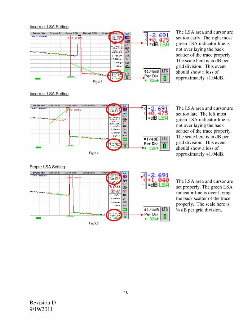
Incorrect LSA Setting
Fig 8.3
Incorrect LSA Setting
Fig 8.4
Proper LSA Setting Fig 8.5
16
The LSA area and cursor are
set too early. The right most
green LSA indicator line is
not over laying the back
scatter of the trace properly.
The scale here is ¼ dB per
grid division. This event
should show a loss of
approximately +1.04dB.
The LSA area and cursor are
set too late. The left most
green LSA indicator line is
not over laying the back
scatter of the trace properly.
The scale here is ¼ dB per
grid division. This event
should show a loss of
approximately +1.04dB.
The LSA area and cursor are
set properly. The green LSA
indicator line is over laying
the back scatter of the trace
properly. The scale here is
¼ dB per grid division.
Revision D
9/19/2011
8.7 Unit of Measure
The distance unit of measure may be either displayed in Kilometer (Km) or Kilo feet (Kf). To change the setting, enter the menu mode, scroll to highlight the Tools icon and press the Select button. Scroll to Unit of Measure and use the Select button to toggle between Km and Kf. Press the Menu button to return to the trace display.
8.8 Quick Save/Recall
Quick Save To use quick save, press the Menu button, scroll to the Save soft key and press the Select button. The trace will be saved to the storage location shown. The file will be stored with the same base file name as the last save stored trace. If the storage location indicated already contains a file, the user will be prompted to either “Overwrite” the location, Save to the “Next” available location or “Cancel” the action. Scroll to the desired action and press Select. The storage location will increment accordingly. Note: There are sample traces stored on the OTDR at the factory. These traces are saved with the base file name of default. Quick Recall To quickly recall a trace, press Menu, scroll to the Recall soft key and press the Select button to display the trace that is saved in the memory location indicated and the next memory location with a trace will be displayed.
8.9 Visual Fault Locator To activate the VFL, press the Menu button and scroll to highlight the VFL icon, press the Select button to cycle
the VFL through CW, Modulated and off. The VFL will not operate while other light sources are active.
WARNING: The VFL is equipped with a 650nm Class II laser. See warning label figure 4.2
17
Revision D
9/19/2011
9.0 Event Analysis
NOTE: When using the event table, it is necessary to keep in mind that event analysis provides approximate loss and distance measurements to quickly assist in network evaluation. Automatic detection results are not guaranteed and have their limits, possibly causing erroneous readings or detection failure. User interaction by interfacing with the trace display is recommended for final qualitative and quantitative analysis.
9.1 Enter/Exit Event Analysis To open the event analysis table, press the Menu button, scroll to highlight Show Event soft key and press the Select button. Use the Scroll Wheel to move through the evens. If the Select button is pressed while an event is highlighted, The OTDR will revert to the Trace Screen with the active cursor positioned at the selected event. An alternative method to return to the trace view is to press the Menu button, scroll to the Show Trace soft key and press the Select button.
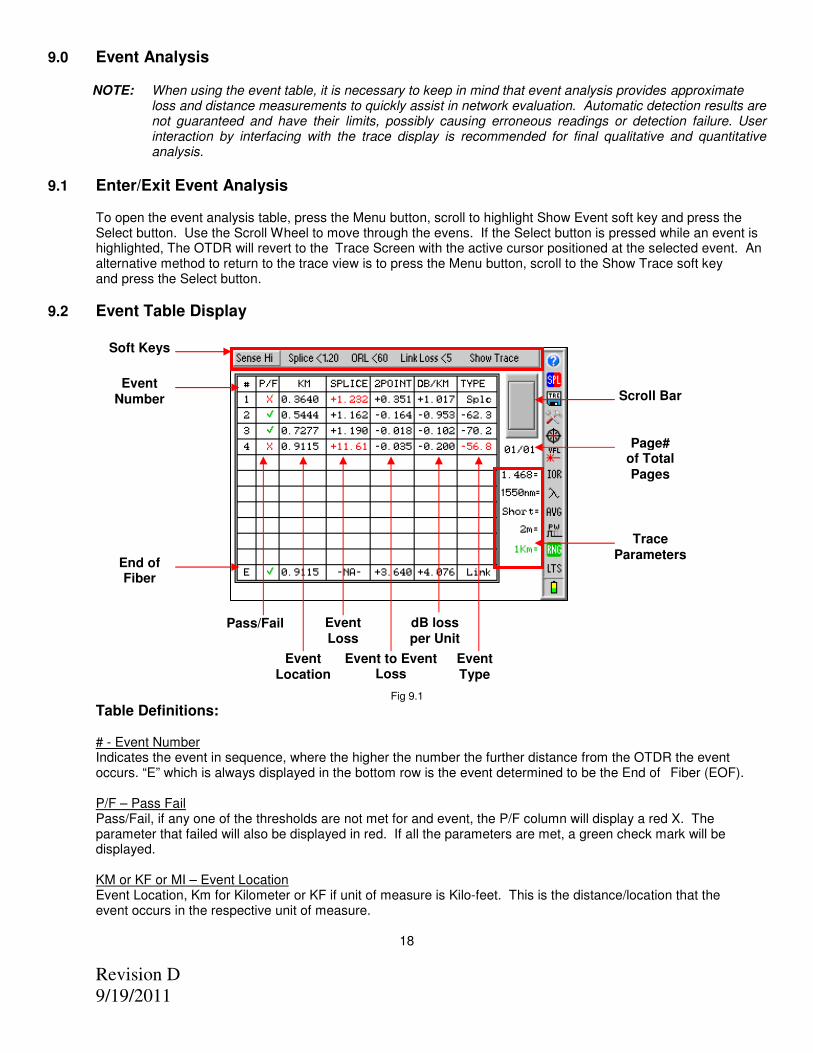
9.2 Event Table Display
Fig 9.1 Table Definitions:
# - Event Number Indicates the event in sequence, where the higher the number the further distance from the OTDR the event occurs. “E” which is always displayed in the bottom row is the event determined to be the End of Fiber (EOF). P/F – Pass Fail Pass/Fail, if any one of the thresholds are not met for and event, the P/F column will display a red X. The parameter that failed will also be displayed in red. If all the parameters are met, a green check mark will be displayed. KM or KF or MI – Event Location Event Location, Km for Kilometer or KF if unit of measure is Kilo-feet. This is the distance/location that the event occurs in the respective unit of measure.
18
Soft Keys
dB loss per Unit
Event Loss
Event Type
Page# of Total Pages
Trace Parameters
Scroll Bar
Event to Event Loss
Event Location
Pass/Fail
Event Number
End of Fiber
Revision D
9/19/2011
SPLICE - Event Loss Event Loss, where a positive number is the amount of loss and a negative number would be indicating a gain. This is a settable threshold for the Pass/Fail feature. 2POINT – Event to Event Loss 2 Point Loss from the end of the dead zone of the previous event to the beginning of current event. DB/KM or KF or MI – Event to Event Loss per Km/Kf/Mi This is the dB loss per unit of the selected unit of measure. Example. If Kilometer is the selected unit of measure, this value is the loss in dB per kilometer from the end of the dead zone of the previous event to the beginning of the current event. TYPE – Type of Event Event Type is the type of event or the ORL measurement. If the event is a splice with no reflection, “splc” will be displayed and if the event contains a reflection, the ORL value will be displayed. This is a settable threshold for the Pass/Fail feature E – End of Fiber End Of Fiber at the bottom of the table will display location for the suspected end of fiber in the KM column, N/A in the Splice Column and Link Loss in the 2 POINT column. Link Loss may be set as a Pass/Fail Threshold. The DB/KM or KF is the calculated dB loss per Km or Kf for the full link and the TYPE column will display the word Link.
To the right of the table is a scroll bar which will be active if the amount of events exceeds one page and below the scroll bar is an indication of what page is display per number of pages. Also on the Event Table display are the parameter settings for the current trace.
9.3 Sensitivity Settings
There are three levels of sensitivity while in the event table. The sensitivity is set via the Sense soft key. Use the Menu button to access the Soft Keys and use the Scroll Wheel to highlight the Sense key. Press the Select button to cycle through HI, for events with loss down to approximately 0.1dB, Medium (Md) with events down to approximately 0.2dB and Low (Lo) for event down to about 0.5dB. Highest sensitivity settings should be used for high signal level, low noise, long pulse, averaged traces.
9.4 Pass/Fail Settings
Splice, ORL and Link are all settable thresholds for Pass/Fail purposes. To set the thresholds, press the Menu button, scroll to highlight desired Soft Key, press the Select button and use the Scroll Wheel to reach the desired value. Press Select button again to lock in the settings. If the trace fails any of the three thresholds, a red X will be displayed in the P/F column and the suspect threshold value will be displayed in red.
Examples: Splice: If a splice needs to be less then 1dB, set the threshold to <1.0. If 1.0 would be accepted, set threshold to 1.01db. ORL: If an ORL needs to be less then -50dB, set the threshold to <50. If 50dB is acceptable, set the threshold to <49. Link: If the link loss needs to be less then 20dB, set the threshold to <20. If 20db link loss is acceptable set the threshold to <21. To return to trace view, press the Menu button, scroll to the Show Trace soft key and press the Select button.
19
Revision D
9/19/2011
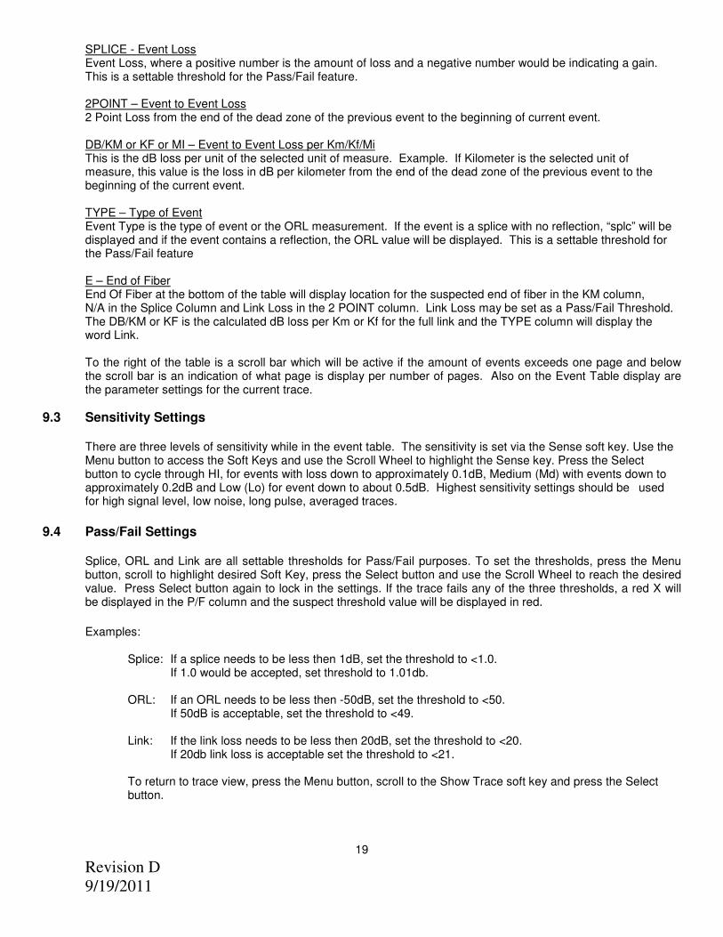
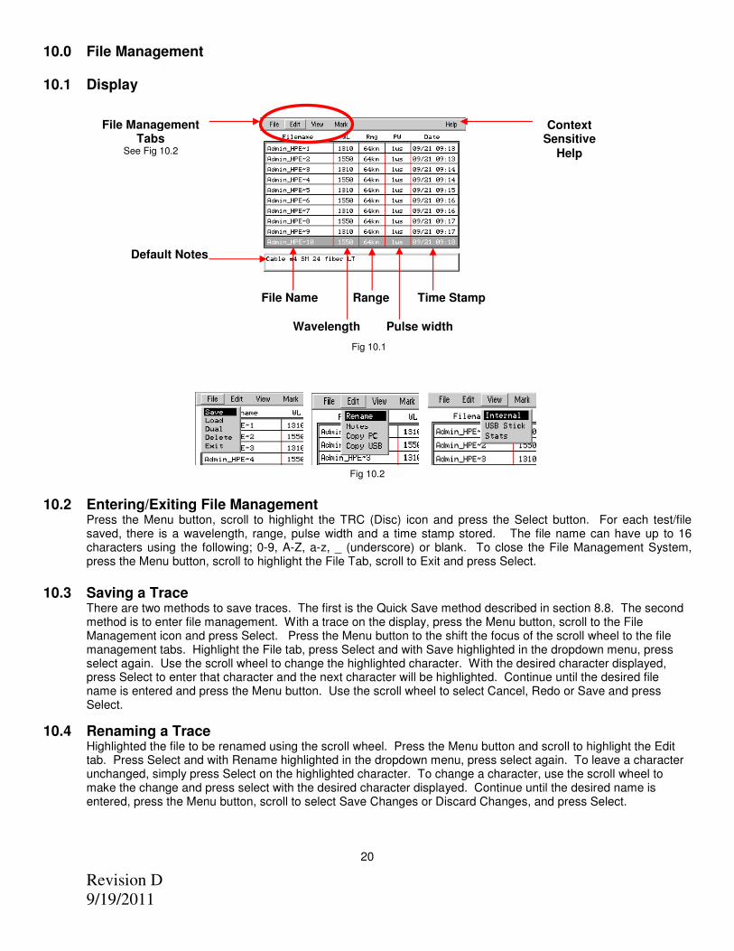
10.0 File Management 10.1 Display Fig 10.1
Fig 10.2 10.2 Entering/Exiting File Management
Press the Menu button, scroll to highlight the TRC (Disc) icon and press the Select button. For each test/file saved, there is a wavelength, range, pulse width and a time stamp stored. The file name can have up to 16 characters using the following; 0-9, A-Z, a-z, _ (underscore) or blank. To close the File Management System, press the Menu button, scroll to highlight the File Tab, scroll to Exit and press Select.
10.3 Saving a Trace
There are two methods to save traces. The first is the Quick Save method described in section 8.8. The second method is to enter file management. With a trace on the display, press the Menu button, scroll to the File Management icon and press Select. Press the Menu button to the shift the focus of the scroll wheel to the file management tabs. Highlight the File tab, press Select and with Save highlighted in the dropdown menu, press select again. Use the scroll wheel to change the highlighted character. With the desired character displayed, press Select to enter that character and the next character will be highlighted. Continue until the desired file name is entered and press the Menu button. Use the scroll wheel to select Cancel, Redo or Save and press Select.
10.4 Renaming a Trace Highlighted the file to be renamed using the scroll wheel. Press the Menu button and scroll to highlight the Edit tab. Press Select and with Rename highlighted in the dropdown menu, press select again. To leave a character unchanged, simply press Select on the highlighted character. To change a character, use the scroll wheel to make the change and press select with the desired character displayed. Continue until the desired name is entered, press the Menu button, scroll to select Save Changes or Discard Changes, and press Select.
20
File Management Tabs
See Fig 10.2
Context Sensitive
Help
Default Notes
Time Stamp Range
Wavelength Pulse width
File Name
Revision D
9/19/2011
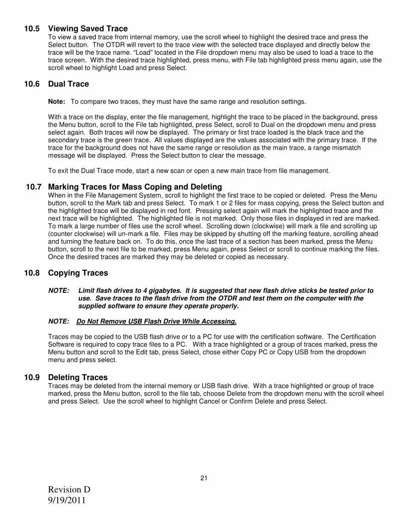
10.5 Viewing Saved Trace To view a saved trace from internal memory, use the scroll wheel to highlight the desired trace and press the Select button. The OTDR will revert to the trace view with the selected trace displayed and directly below the trace will be the trace name. “Load” located in the File dropdown menu may also be used to load a trace to the trace screen. With the desired trace highlighted, press menu, with File tab highlighted press menu again, use the scroll wheel to highlight Load and press Select.
10.6 Dual Trace Note: To compare two traces, they must have the same range and resolution settings.
With a trace on the display, enter the file management, highlight the trace to be placed in the background, press the Menu button, scroll to the File tab highlighted, press Select, scroll to Dual on the dropdown menu and press select again. Both traces will now be displayed. The primary or first trace loaded is the black trace and the secondary trace is the green trace. All values displayed are the values associated with the primary trace. If the trace for the background does not have the same range or resolution as the main trace, a range mismatch message will be displayed. Press the Select button to clear the message.
To exit the Dual Trace mode, start a new scan or open a new main trace from file management.
10.7 Marking Traces for Mass Coping and Deleting When in the File Management System, scroll to highlight the first trace to be copied or deleted. Press the Menu button, scroll to the Mark tab and press Select. To mark 1 or 2 files for mass copying, press the Select button and the highlighted trace will be displayed in red font. Pressing select again will mark the highlighted trace and the next trace will be highlighted. The highlighted file is not marked. Only those files in displayed in red are marked. To mark a large number of files use the scroll wheel. Scrolling down (clockwise) will mark a file and scrolling up (counter clockwise) will un-mark a file. Files may be skipped by shutting off the marking feature, scrolling ahead and turning the feature back on. To do this, once the last trace of a section has been marked, press the Menu button, scroll to the next file to be marked, press Menu again, press Select or scroll to continue marking the files. Once the desired traces are marked they may be deleted or copied as necessary.
10.8 Copying Traces
NOTE: Limit flash drives to 4 gigabytes. It is suggested that new flash drive sticks be tested prior to use. Save traces to the flash drive from the OTDR and test them on the computer with the supplied software to ensure they operate properly. NOTE: Do Not Remove USB Flash Drive While Accessing. Traces may be copied to the USB flash drive or to a PC for use with the certification software. The Certification Software is required to copy trace files to a PC. With a trace highlighted or a group of traces marked, press the Menu button and scroll to the Edit tab, press Select, chose either Copy PC or Copy USB from the dropdown menu and press select.
10.9 Deleting Traces
Traces may be deleted from the internal memory or USB flash drive. With a trace highlighted or group of trace marked, press the Menu button, scroll to the file tab, choose Delete from the dropdown menu with the scroll wheel and press Select. Use the scroll wheel to highlight Cancel or Confirm Delete and press Select.
21
Revision D
9/19/2011
10.10 Adding Default Notes. A note may be saved with a trace. With a file highlighted, entering a note will save that note for that one trace. To save a note for subsequent files, while an empty file storage position is highlighted, enter a note and this note will be saved with all traces until the note is changed. To enter notes, while in the file management screen, press the Menu button, scroll to the Edit tab and press Select. Use the scroll wheel to choose Notes from the dropdown menu and press select. The first character of the notes field will be highlighted. Use the scroll wheel to choose a character and press Select. To erase a character or enter a space, scroll back to the “blank” which is the first character available. If a mistake is made, it may be best to exit the Note field by pressing the Menu button, and reenter the notes field from the Edit dropdown. Once you have completed the note, press Menu to exit.
10.11 Accessing Flash Drive
NOTE: Do Not Remove USB Flash Drive While Accessing.
To access the flash drive, while in file management, press the Menu Button and scroll to the View tab, press Select and choose USB Stick from the dropdown menu. To return to the internal memory, press the Menu button, return to the View dropdown and chooses Internal. All of the Tab functions available for the internal memory are also available for the Flash drive.
10.12 Internal Memory Statistics
The amount of storage available in the onboard memory is found in the Internal Memory Statistics screen. To view this screen; while in file management, press Menu, scroll to the View tab and select Stats from the dropdown menu. This will indicate the percentage of memory used and how many more traces of a specific range may be saved.
22
Revision D
9/19/2011
11.0 Loss Test Set Description
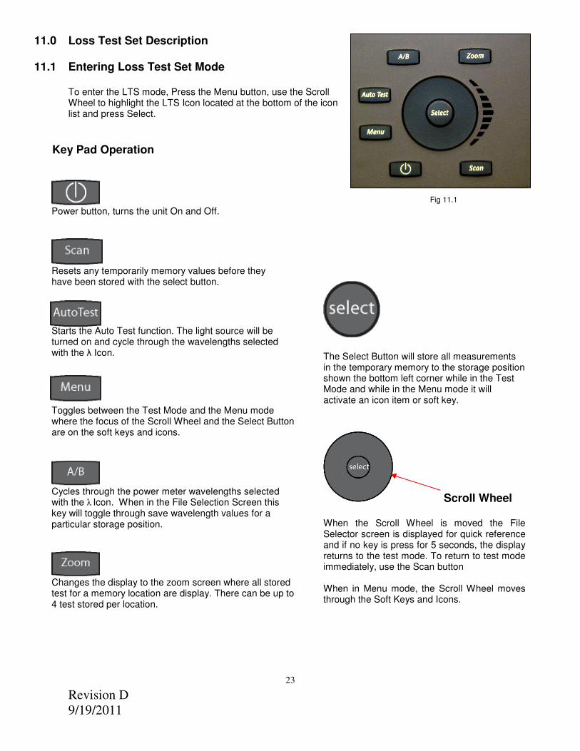
11.1 Entering Loss Test Set Mode To enter the LTS mode, Press the Menu button, use the Scroll Wheel to highlight the LTS Icon located at the bottom of the icon list and press Select.
Key Pad Operation
Fig 11.1
23
Power button, turns the unit On and Off.
Resets any temporarily memory values before they have been stored with the select button.
Starts the Auto Test function. The light source will be turned on and cycle through the wavelengths selected with the λ Icon.
Toggles between the Test Mode and the Menu mode where the focus of the Scroll Wheel and the Select Button are on the soft keys and icons.
Cycles through the power meter wavelengths selected with the λ
Icon. When in the File Selection Screen this
key will toggle through save wavelength values for a particular storage position.
Changes the display to the zoom screen where all stored test for a memory location are display. There can be up to 4 test stored per location.
The Select Button will store all measurements in the temporary memory to the storage position shown the bottom left corner while in the Test Mode and while in the Menu mode it will activate an icon item or soft key.
Scroll Wheel When the Scroll Wheel is moved the File Selector screen is displayed for quick reference and if no key is press for 5 seconds, the display returns to the test mode. To return to test mode immediately, use the Scan button When in Menu mode, the Scroll Wheel moves through the Soft Keys and Icons.
Revision D
9/19/2011
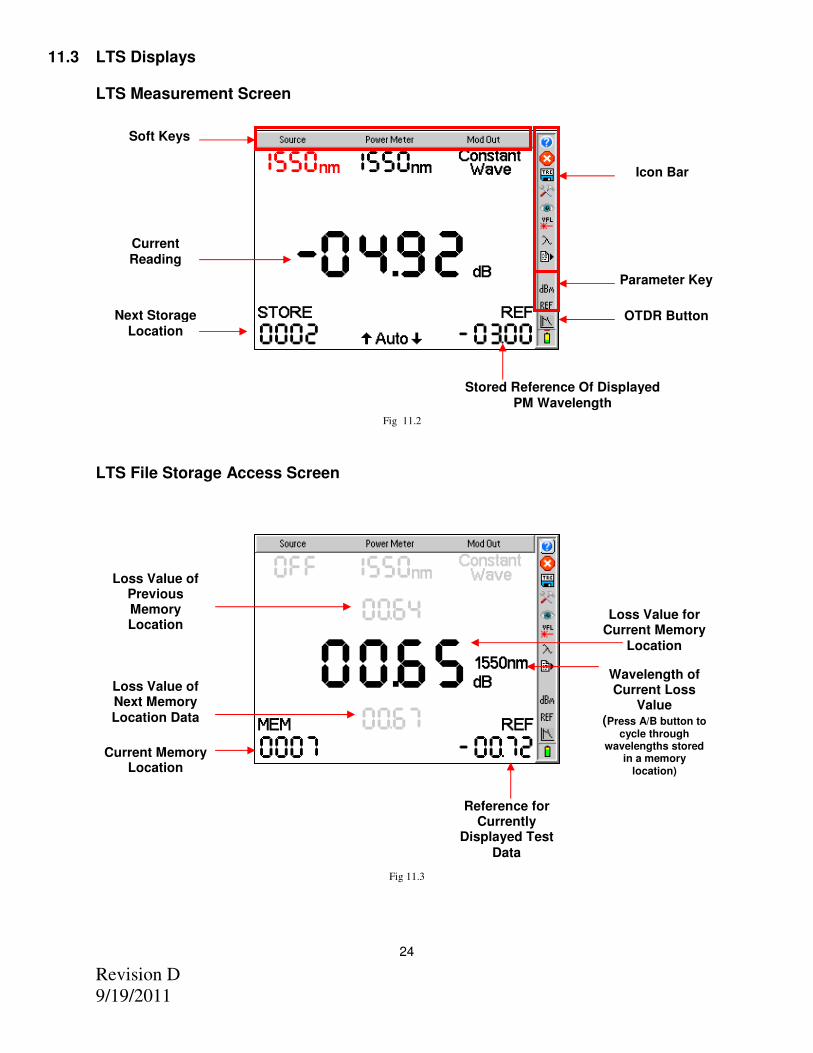
11.3 LTS Displays LTS Measurement Screen
Fig 11.2 LTS File Storage Access Screen
Fig 11.3
24
Stored Reference Of Displayed PM Wavelength
Current Reading
Next Storage Location
Parameter Key
Icon Bar
Soft Keys
OTDR Button
Loss Value for Current Memory
Location
Current Memory Location
Loss Value of Next Memory Location Data
Loss Value of Previous Memory Location
Reference for Currently
Displayed Test
Data
Wavelength of Current Loss
Value (Press A/B button to
cycle through wavelengths stored
in a memory location)
Revision D
9/19/2011
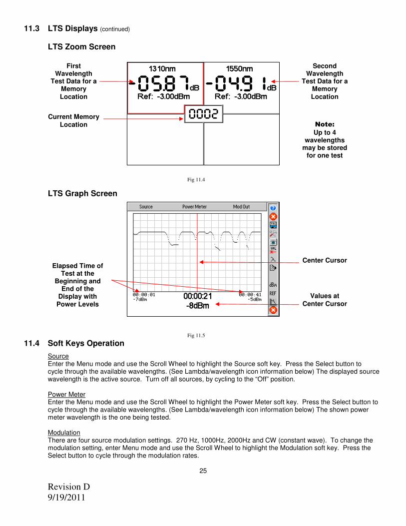
11.3 LTS Displays (continued)
LTS Zoom Screen
Fig 11.4
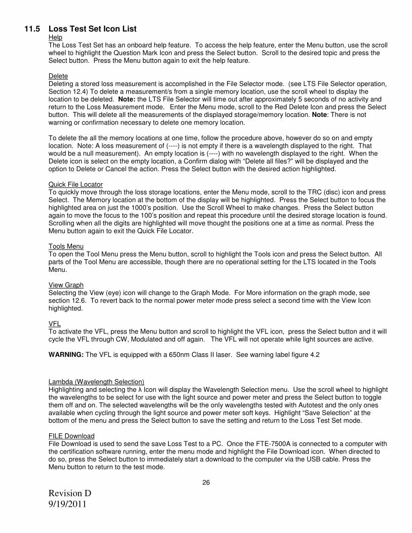
LTS Graph Screen
Fig 11.5 11.4 Soft Keys Operation
Source Enter the Menu mode and use the Scroll Wheel to highlight the Source soft key. Press the Select button to cycle through the available wavelengths. (See Lambda/wavelength icon information below) The displayed source wavelength is the active source. Turn off all sources, by cycling to the “Off” position. Power Meter Enter the Menu mode and use the Scroll Wheel to highlight the Power Meter soft key. Press the Select button to cycle through the available wavelengths. (See Lambda/wavelength icon information below) The shown power meter wavelength is the one being tested.
Modulation There are four source modulation settings. 270 Hz, 1000Hz, 2000Hz and CW (constant wave). To change the modulation setting, enter Menu mode and use the Scroll Wheel to highlight the Modulation soft key. Press the Select button to cycle through the modulation rates.
25
Center Cursor Elapsed Time of
Test at the Beginning and
End of the Display with Power Levels
Second Wavelength
Test Data for a Memory Location
First Wavelength
Test Data for a Memory Location
Current Memory Location
Values at Center Cursor
Note:
Up to 4 wavelengths
may be stored for one test
Revision D
9/19/2011
11.5 Loss Test Set Icon List Help The Loss Test Set has an onboard help feature. To access the help feature, enter the Menu button, use the scroll wheel to highlight the Question Mark Icon and press the Select button. Scroll to the desired topic and press the Select button. Press the Menu button again to exit the help feature. Delete Deleting a stored loss measurement is accomplished in the File Selector mode. (see LTS File Selector operation, Section 12.4) To delete a measurement/s from a single memory location, use the scroll wheel to display the location to be deleted. Note: the LTS File Selector will time out after approximately 5 seconds of no activity and return to the Loss Measurement mode. Enter the Menu mode, scroll to the Red Delete Icon and press the Select button. This will delete all the measurements of the displayed storage/memory location. Note: There is not warning or confirmation necessary to delete one memory location. To delete the all the memory locations at one time, follow the procedure above, however do so on and empty location. Note: A loss measurement of (----) is not empty if there is a wavelength displayed to the right. That would be a null measurement). An empty location is (----) with no wavelength displayed to the right. When the Delete icon is select on the empty location, a Confirm dialog with “Delete all files?” will be displayed and the option to Delete or Cancel the action. Press the Select button with the desired action highlighted. Quick File Locator To quickly move through the loss storage locations, enter the Menu mode, scroll to the TRC (disc) icon and press
Select. The Memory location at the bottom of the display will be highlighted. Press the Select button to focus the highlighted area on just the 1000’s position. Use the Scroll Wheel to make changes. Press the Select button again to move the focus to the 100’s position and repeat this procedure until the desired storage location is found. Scrolling when all the digits are highlighted will move thought the positions one at a time as normal. Press the Menu button again to exit the Quick File Locator.
Tools Menu To open the Tool Menu press the Menu button, scroll to highlight the Tools icon and press the Select button. All
parts of the Tool Menu are accessible, though there are no operational setting for the LTS located in the Tools Menu.
View Graph Selecting the View (eye) icon will change to the Graph Mode. For More information on the graph mode, see
section 12.6. To revert back to the normal power meter mode press select a second time with the View Icon highlighted.
VFL To activate the VFL, press the Menu button and scroll to highlight the VFL icon, press the Select button and it will
cycle the VFL through CW, Modulated and off again. The VFL will not operate while light sources are active.
WARNING: The VFL is equipped with a 650nm Class II laser. See warning label figure 4.2
Lambda (Wavelength Selection) Highlighting and selecting the λ Icon will display the Wavelength Selection menu. Use the scroll wheel to highlight
the wavelengths to be select for use with the light source and power meter and press the Select button to toggle them off and on. The selected wavelengths will be the only wavelengths tested with Autotest and the only ones available when cycling through the light source and power meter soft keys. Highlight “Save Selection” at the bottom of the menu and press the Select button to save the setting and return to the Loss Test Set mode.
FILE Download File Download is used to send the save Loss Test to a PC. Once the FTE-7500A is connected to a computer with
the certification software running, enter the menu mode and highlight the File Download icon. When directed to do so, press the Select button to immediately start a download to the computer via the USB cable. Press the Menu button to return to the test mode.
26
Revision D
9/19/2011
12.0 Loss Test Set Operation
12.1 Power Meter Measurements
Power Measurements
With the FTE-7500A in Loss Test Set Mode. Connect the fiber carrying the optical power to be measured to the
Power Meter detector utilizing the appropriate adaptor. Select the power meter wavelength that matches the
wavelength of the light being measured. The power reading will now indicate the optical power in units of dBm. If
the power level is greater than +5 or less than -77 dBm the display will indicate an out-of-range condition by a
series of dashes across the main display. For higher power, ask a representative about a CATV version power
meter.
To save the power measurement to the storage location indicated below the STORE label press the Select
button. The memory location will auto increment to the next available memory location.
Relative Measurements
To make a relative power measurement you must first save the reference power level. To store a reference level,
attach reference cord/s and energize the light source. Enter the Menu mode, scroll to Ref icon and press the
Select button. The reference is now stored in non volatile memory and displayed at the bottom right of the
display. The units of the display will now change to dB. Subsequent readings will now be displayed in terms of dB
relative to the stored reference value. A reference memory location is available for each selected wavelength. A
reference reading is required to change to dB measurement from dBm measurements.
Remove the connector from the power meter port and place the fiber under test inline between the reference cord
and the power meter port. The reading displayed will be the loss of the fiber under test relative to the reference.
Ensure the unit is not in Menu mode and press the Select button to store the measurement.
Stored power measurements may be recalled by moving the Scroll Wheel and the File Selector Screen will be displayed. If no buttons are press for 5 seconds after entering the File Selector mode, the unit will revert to the test mode. The Scan button may also be pressed to re-enter test mode.
12.2 Loss Test Set AUTO TEST
To use the Auto Test feature, connect the fiber to be tested to a compatible test set. The unit being used as the
power meter should be in loss test set mode. The unit being used as the source should be set to Autotest. If Two
Quad OTDRs are being used, only the wavelengths to be tested should be selected as sources by entering the
Wavelength/Lambda selection menu. Only the wavelengths that are energized will be displayed on the power
meter end. Once the source and power meter have cycled through the wavelengths to be tested, press the
Select button to store the measurements. .
Note: A reference measurement is not used in the Auto Test Mode. The Source is modulated and has power
level of -3dBm (-6dBm@1625). This method of measurement does not take into account the launch condition,
thus the manual method of testing should be used when highly accurate measurements are required such as
when testing the loss of an individual connector. The Auto Test annunciator will be displayed during Auto Test
loss measurements. Two or more loss measurements are best viewed in the Zoom mode where all the selected
wavelengths will be display at one time on the display.
12.3 Loss Test Set Light Source Operation
Energizing Light Source
The lasers are initially in the off state when the LTS is launched. Enter the Menu mode and use the Scroll Wheel
to highlight the Source soft key. Pressing Select will energize the available wavelengths in sequence. If used
with a compatible test set or a companion FTE-7500A, The light source will transmit the wavelength information
automatically to the receiving unit which then changes the power meter wavelength setting to correspond to the
wavelength of the light source.
For compatible light sources or test sets, please contact your TTI sales associate.
27
Revision D
9/19/2011
Modulating Light Source Change the modulation of the light source by entering Menu mode and scrolling to highlight the Modulation soft key. Pressing the select button will toggle through available modulation rates of CW, 270Hz, 1000Hz, and 2000Hz. The rate will be displayed directly under the Modulation soft key. Note that when measuring average power of the lasers the output will drop by exactly 3.01 dB as the source is off precisely half of the time. The modulation function is useful for fiber identification and for general purpose optical component testing. The unit that receives one of the modulated frequencies will flash the appropriate frequency annunciator. (The 3.01dB drop is also true of the laser output when in the Auto Test mode however the unit receiving this signal automatically compensates for the loss in average power and this is transparent to the user.)
12.4 LTS File Selector Operation
File Selector Screen Enter the File Selector Screen with the scroll wheel. In the File Selector screen the soft keys will be inactive and grayed out. The Store location in the bottom left of the screen will be changed to MEM location and there will be three loss values on the display. The middle one is the measurement stored in the indicated memory location with the wavelength of the reading to the right. Pressing the A/B button will cycle through the readings stored in that location if more than one wavelength was stored. The grayed out readings above and below the main reading, are the measurements of the previous and next memory locations. If there is not activity in 5 seconds, the screen will revert back to the Test Mode. The Scan button will also revert the unit to the test mode. NOTE: Pressing the Select button will overwrite the displayed test with whatever is in the temporary memory location. Four dashes without a wavelength indicator next to them represents an empty memory location if a wavelength indicator is displayed next to the four dashes, there is a null test stored to that location for the displayed wavelength. This test could be under or over scale. Quick File Locator To quickly move through the loss storage locations, enter the Menu mode, scroll to the TRC (disc) icon and press Select. The Memory location at the bottom of the display will be highlighted. Press the Select button to focus the highlighted area on just the 1000’s position. Use the Scroll Wheel to make changes. Press the Select button again to move the focus to the 100’s position and repeat this procedure until the desired storage location is found. Scrolling when all the digits are highlighted will move thought the positions one at a time as normal. Press the Menu button again to exit the Quick File Locator.
12.5 LTS File Transfer Operation
To transfer files from the Loss Test Set to the computer, start the certification software. Connect the OTDR to the computer with the supplied USB cable, go to the tools tab of the software, and select Baud Rate and choose Auto Detect or desired baud rate. Return to Tools Tab and select Download LTS Files, enter a file name and press Save. The Software will prompt the user to start the Loss Test Set memory download from the OTDR. To start the memory download, enter Menu mode, highlight the File Download Icon and press Select. The download progress will be indicated by the UPLOAD counter in the bottom left corner of the display. Note: If there is a communication error occurs, ensure you turn off and restart the OTDR.
12.6 Loss Test Set Graph Mode Operation
To view measurements in the Graph Mode, press the Menu button, scroll to the Light Source soft key and use the Select button to cycle to the desired wavelength for the test. If a source other than one compatible for auto-wavelength recognition with the OTDR is being used, ensure the proper power meter wavelength is selected. Once the source is energized and the power meter is taking a measurement, enter the Menu mode, scroll to the Eye Icon (view), press Select and the Scan button to start the graph. Pressing the Scan button again will stop the graph. The elapsed time of the scan is noted at the beginning middle and end of the graph with the absolute value at each of those points displayed. The graph may also be viewed on the certification software. Please refer to the software for information on how to display the graph view on the computer. To exit the Graph Mode, press the select button again with the Eye Icon (view) highlighted.
28
Revision D
9/19/2011
13.0 Maintenance 13.1 Battery Replacement
Battery replacement is not recommended however if you must replace the batteries follow these procedures. Carefully remove unit from protective boot and remove the two screws from top plate and bottom plate that retain the back cover. Carefully remove back cover and remove the two screws that hold the battery covers in place. Replace only with 8 AA NiMH 2500mAh batteries. If you install NiMH batteries that are dead or less than 1 volt each, charge these batteries for one (1) hour before using the Advanced OTDR. For maintenance, batteries require a monthly periodic recharge. WARNING: To Prevent Fire or Shock Hazard: Do not install other battery types; Do not use the battery charger without the batteries installed; Do not expose the battery charger to rain or excessive moisture; Do not use the battery charger when there are signs of damage to the enclosure or cord; Ensure that you are using the correct charger for the local line voltage; Do not use any other battery charger than the one provided with this instrument. Any other condition will void the warranty.
For maintenance, batteries require a monthly periodic recharge.
13.2 Clock Battery In order to ensure proper Time and Date stamps on test data, it is necessary to energize the Advanced OTDR for a minimum of 5 minutes per month. If this is not accomplished, it will be necessary to reset the time and date information in the Tools Menu.
13.3 Laser Out Port
Do not under any circumstance view or inspect the laser output fibers, connectors, or the fiber under test through collimating or focusing optics. A video inspection microscope should be used to examine all fiber ends. Contact your TTI sales representative for video microscope information. WARNING: Never clean or look directly into the fiber optic connector or the end of fiber attached to the OTDR or VFL unit while they are energized, to do so will expose the user to laser radiation and could result in personal injury or instrument damage. WARNING: Before connecting to a patch cord or fiber under test, be certain the fiber has no active optical sources or instruments connected to the other end. Skin or eye damage could result from other high power sources e.g. EDFAs, or instrument damage could occur voiding the warranty. In order to maintain a low loss fiber connection, care should be taken to adequately clean the ferrule of any connector to be inserted in the Laser Out Port. In the event that the port needs to be cleaned, first step is to be certain the instrument is off. We suggest the use of isopropyl alcohol and foam swabs specifically designed for cleaning connectors accepting 2.5mm ferrules.
13.4 Recalibration and Verification
Periodic verification of the ADVANCED OTDR is recommended to ensure that your instrument remains within specification. Although not imperative, we recommend a recalibration and verification once a year to make certain the instrument is functioning properly and performing to its rated specifications. Consult the factory for service.
29
Revision D
9/19/2011
13.6 OTDR Adapter Replacement The OTDR is supplied with three easily interchangeable adapters per port, ST/SC/FC. To change an adapter, remove the two screws that hold the adapter in place, pull the adapter straight up from ferrule. It is suggested that you clean the exposed ferrule with appropriate cleanser and lint free wipe anytime you replace the ferrule. NOTE: When replacing the adapter with one that does not have a chained protective cap, use the small screw in place of the larger screw that retains the end of the chain to the adapter base.
30
Revision D
9/19/2011
14.0 Application Information. Optical Time Domain Reflectometer Measurements.
The TTI OTDR is designed to be used as an installation, troubleshooting, and maintenance tool. The Advanced OTDR is a full featured Optical Time Domain Reflectometer, but unlike OTDRs that cost thousands of dollars more, the Advanced OTDR is very simple to operate. The TTI OTDR measures distance and loss of fiber links up to 240Km by launching an optical pulse down one end of the fiber and analyzing the returned energy in time (or distance) from reflections. The Advanced OTDR uses an advanced high speed embedded controller and display processor with proprietary technology to analyze, store and average the fiber trace data in the quickest time. This high speed processing engine allows the user to make distance and loss measurements immediately after energizing the instrument. With its advanced Event Table, Splice Loss Mode and dB/Km Mode, it also can assist the user in interpreting major events such as bad splices, connections or broken ends. Minor perturbations along otherwise normal fiber links can also be detected using a simple moving cursor approach in Splice Loss Mode. Complex return signals with many major or minor events can be analyzed by the Advanced OTDR then stored away for archiving and later retrieval. As with any OTDR to assist in obtaining reliable, consistent measurements, the user must be aware of the Index of Refraction of their fiber or cable. The fiber Index of Refraction (IOR) is an important parameter that must be entered by the user to maximize the distance measurement accuracy. The IOR is proportional to the speed of light in glass compared to the speed in a vacuum and can be calculated by the equation IOR = C (the speed of light in a vacuum) / V (the speed of light in fiber). The IOR number can be obtained by the fiber or cable manufacturer or can be calculated with a known length of cable. IOR numbers generally fall around 1.468 SM, 1.486 MM. These are the default values in the OTDR, but can be adjusted from 1.0 to 2.0. To calibrate the IOR for your particular fiber, take a known distance of fiber or cable (best if around 1 kilometer), and measure the distance with the Advanced OTDR set for 2m pulse width, changing the IOR until the measured distances closely match. An error of .001 of the IOR entry (1.468 vs. 1.469) equates to an error of approximately 0.7 meters per kilometer of distance measured.
31
Revision D
9/19/2011
15.0 Specifications
Advanced OTDR Specifications Wavelength 850, 1300, 1310, 1490, 1550, 1625nm ±20nm Dynamic Range 27/26dB MM, 36/34dB SM, 36/34/34dB TRI
Pulse Width 5 - 20,000 ns Units of Measurement km, kf Event Dead zone 1m
Attenuation Dead Zone 5m Resolution .125 - 32m
Distance Range 1-64km MM , 1-240km SM Typical Real-time Refresh Rate Up to 2 Hz Group Index of Refraction (GIR) 1.000 - 2.000
Linearity ± .05 dB/dB
Memory Capacity ~500
Memory Type Internal and Flash Drive Connector Styles FC, ST, SC Interchangeable
Visible Light Source Emitter Type Laser Wavelength 650nm ±5nm
Laser Safety Class Class IIFDA21 CFR1040.10 &1040.11 IEC 825-1: 1993 Connector Type 2.5mm Universal
Output Power <1mW Max.
Power Meter Power Meter Detector Type InGaAs
Calibrated Wavelength 850, 1300, 1310, 1490, 1550, 1625 Units of Measure dBm, dB
Resolution 0.01 dB Power Measurement Range +5 dBm to -77 dBm (CATV +25 dBm to -57 dBm)
Power Measurement Uncertainty ± 0.18 dB under reference conditions, ±0.25 dB from 0 to -65 dBm, ± 0.35 dB from 0 to +5 dBm and from -65 to -77 dBm
Autotest Measurement Rate Four seconds per wavelength
Autotest Range 0 to -36 dB Storage Locations 10,000
Connector Interchangeable ST/SC/FC
Light Source Wavelengths 850, 1300, 1310,1550, 1625 ±20nm Output Power (CW) 0 dBm (-3dBm@1625nm) Laser Safety Classification Class I safety per FDA/CDRH and IEC-825-1 regulations
Modulation Modes CW, 270 Hz, 1000 Hz, 2000 Hz
General Specifications Battery Charger Universal Battery 8hr
Dimensions (without rubber boot ) 7.75” L x 4.5” W x 2.25” H (197mm L x 114mm W x 57mm H)
Weight 2 lbs
Communications ports USB PC and USB Flash Drive Ports Storage Temperature -20 to 60 C
Operating Temperature Range -10 to 50 C Accessories Provided Universal Battery Charger w/US, UK, Continental Europe, and
Australian Plugs, Interchangeable FC/ST and SC Adapters, Windows/Telcordia SR4731 Software, Rubber Boot
Specifications are subject to change without notice
32
Revision D
9/19/2011
16.0 Warranty / Repair / Trouble Shooting 16.1 Warranty Information
This product, including all mechanical, electrical, and optical parts and assemblies are unconditionally warranted to be free of defects in workmanship and material for a period of one (1) year from the date of delivery. This warranty does not apply to expendable parts such as batteries, nor to any instrument or component which has been subjected to misuse, alteration, or fiber connector damage. It is the customer’s responsibility to understand all the instructions and specifications prior to operating this instrument. This warranty does not extend to any loss or damage consequent to the failure of the warranted product.
16.2 Repair
If repair is required, simply call Terahertz Technologies, Inc. @ 315-736-3642 for return instructions and a RMA number.
16.3 Troubleshooting
Symptom Possible Cause Solution
LCD dark Power not on Batteries require recharging Batteries are missing, in backwards or need replacement
Press ON/OFF key Recharge batteries
Check polarity, replace batteries, or contact factory for servicing
LCD white Power cycled too quickly Turn off wait 5 seconds – turn on
Instrument locked Up
Unexpected Operational Mode Turn off (hold ON/OFF button in for 1 second) wait 5 seconds – then depress On/Off again button to turn the unit on.
Initial Backscatter low
Defective cord or dirty connector Fiber Output port requires cleaning Angle polish mated with UPC polish
Replace or clean cord Clean and inspect port Examine connector ends
Extra or “ghost” reflections on backscatter
Fiber too long for short pulse Fiber over 16Km/53Kft Fiber over 64Km/200Kft
Switch to 10m pulse if >4Km Switch to 100m pulse if >16Km
Switch to 1km Mode if >64Km
USB hookup to PC not functioning properly
USB baud rate not set properly or too quick for computer PC drivers not set properly
Set port baud rate properly or decrease Baud rate in instrument and certification software Uninstall & reinstall certification software and drivers
USB Flash Driver not functioning properly
USB flash drive full USB flash driver cycled too quickly
Clean or use a new flash drive
Turn power off wait 5 seconds turn back on.
33
Revision D
9/19/2011
17.0 Version Control Through a program of continuous improvement the upgrade of the features and performance of this instrument are an on going process. The instrument firmware version is accessible at “turn-on”. The version is displayed on the bottom right-hand corner of the display. The version changes and approximate release dates are as follows. V1.3 - 06/2009 - Original Release V1.4 - 09/2010 - Added Construction Mode, Default Notes and Miles as a unit of measure. Requires a minimum of version 4.5.6 software. V2.0– 09/2011 - Incorporated Hi-Resolution and increased dynamic