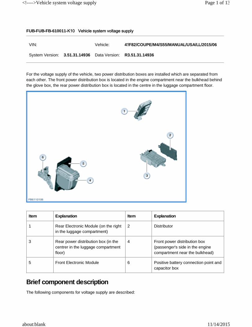
FUB-FUB-FB-610011-K10 Vehicle system voltage supply For the voltage supply of the vehicle, two power distribution boxes are installed which are separated from each other. The front power distribution box is located in the engine compartment near the bulkhead behind the glove box, the rear power distribution box is located in the centre in the luggage compartment floor. Brief component description The following components for voltage supply are described: VIN: Vehicle: 4'/F82/COUPE/M4/S55/MANUAL/USA/LL/2015/06 System Version: 3.51.31.14936 Data Version: R3.51.31.14936 Item Explanation Item Explanation 1 Rear Electronic Module (on the right in the luggage compartment) 2 Distributor 3 Rear power distribution box (in the centrer in the luggage compartment floor) 4 Front power distribution box (passenger's side in the engine compartment near the bulkhead) 5 Front Electronic Module 6 Positive battery connection point and capacitor box Page 1 of 13 <!---->Vehicle system voltage supply 11/14/2015 about:blank
Transcript
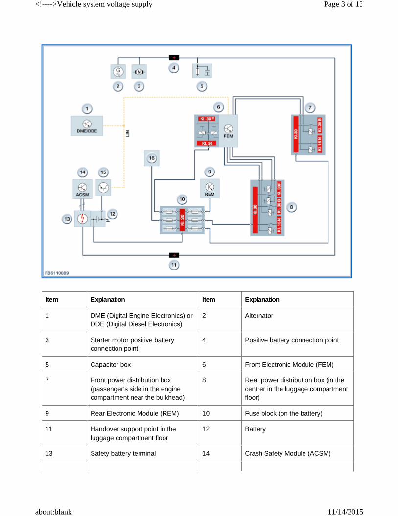
FUB-FUB-FB-610011-K10 Vehicle system voltage supply
For the voltage supply of the vehicle, two power distribution boxes are installed which are separated from each other. The front power distribution box is located in the engine compartment near the bulkhead behind the glove box, the rear power distribution box is located in the centre in the luggage compartment floor.
Brief component descriptionThe following components for voltage supply are described:
BatteryThe vehicle battery is fitted in the centre at the rear of the luggage compartment floor. An AGM battery is almost always installed. The capacity of the AGM battery depends on the vehicle type and the vehicle equipment: 80 Ah or 90 Ah.The AGM battery primarily offers the advantage of greater rechargeability.There are also vehicle types where a 12 V lithium ion battery is installed.
Notice! Battery type and battery capacityWhen replacing an AGM battery, the replacement must always have the same or higher battery capacity.
IBS: Intelligent battery sensorThe intelligent battery sensor (IBS) is a mechatronic component with its own microcontroller for monitoring the battery condition. The IBS continuously measures the following values on the battery:
For the data transfer, the IBS is connected with the engine electronics and the front electronic module via a Local Interconnect Network bus (LIN bus).The IBS is installed in the battery in the case of the 12 V lithium ion battery.The intelligent battery sensor installed enables better determination of the battery condition: Identification of faulty battery cells, determining remaining battery capacity.Refer to following functional description: Intelligent battery sensor and battery
AlternatorWith the engine running, the alternator generates a variable charging voltage for battery charge. The variable charging voltage is influenced by the power management depending on the temperature and current by the DME/DDE raising the engine speed.
Fuse block on the batteryThe fuse block can only be completely renewed. Fuses cannot be renewed individually.The fuse block contains fuses for the following consumer units:
15 Intelligent battery sensor (IBS) 16 Electronics box (power distribution box in the engine compartment)
Kl. 30 Terminal 30 Kl. 30B Terminal 30B
Terminal 30F Terminal 30F Terminal 15N
Terminal 15N (after-run)
LIN bus Local interconnect network bus
- Voltage.
- Charge and discharge current.
- Battery temperature.
Page 4 of 13<!---->Vehicle system voltage supply
11/14/2015about:blank
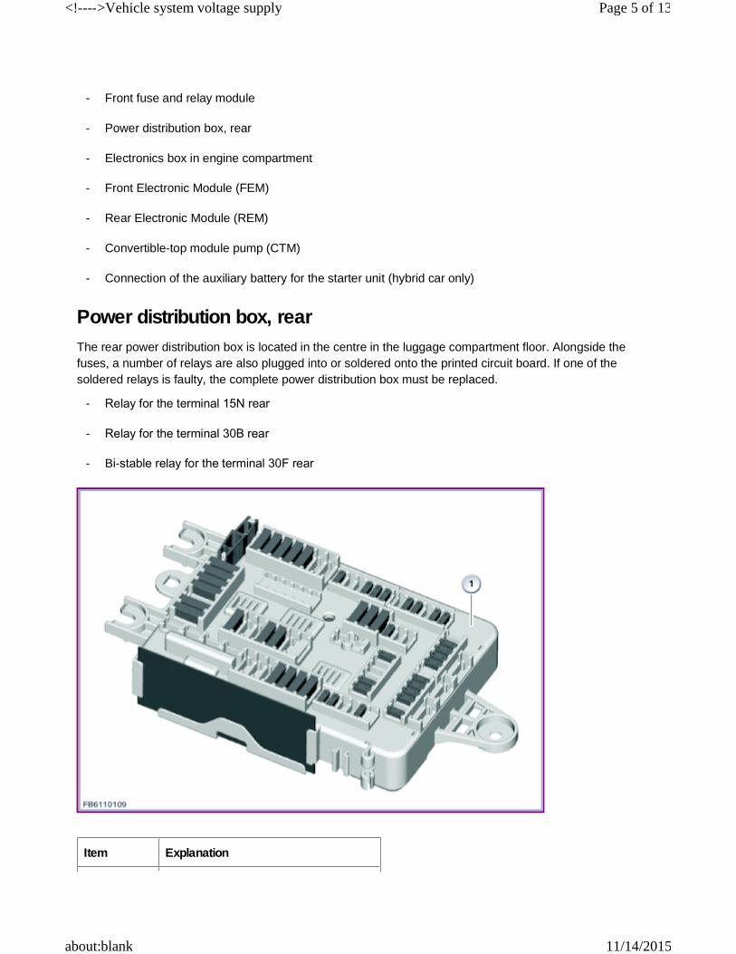
Power distribution box, rearThe rear power distribution box is located in the centre in the luggage compartment floor. Alongside the fuses, a number of relays are also plugged into or soldered onto the printed circuit board. If one of the soldered relays is faulty, the complete power distribution box must be replaced.
- Front fuse and relay module
- Power distribution box, rear
- Electronics box in engine compartment
- Front Electronic Module (FEM)
- Rear Electronic Module (REM)
- Convertible-top module pump (CTM)
- Connection of the auxiliary battery for the starter unit (hybrid car only)
- Relay for the terminal 15N rear
- Relay for the terminal 30B rear
- Bi-stable relay for the terminal 30F rear
Item Explanation
Page 5 of 13<!---->Vehicle system voltage supply
11/14/2015about:blank
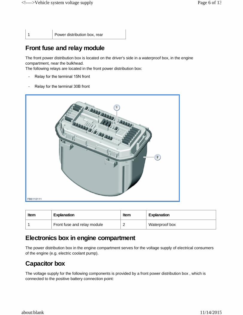
Front fuse and relay moduleThe front power distribution box is located on the driver's side in a waterproof box, in the engine compartment, near the bulkhead.The following relays are located in the front power distribution box:
Electronics box in engine compartmentThe power distribution box in the engine compartment serves for the voltage supply of electrical consumers of the engine (e.g. electric coolant pump).
Capacitor boxThe voltage supply for the following components is provided by a front power distribution box , which is connected to the positive battery connection point:
1 Power distribution box, rear
- Relay for the terminal 15N front
- Relay for the terminal 30B front
Item Explanation Item Explanation
1 Front fuse and relay module 2 Waterproof box
Page 6 of 13<!---->Vehicle system voltage supply
11/14/2015about:blank
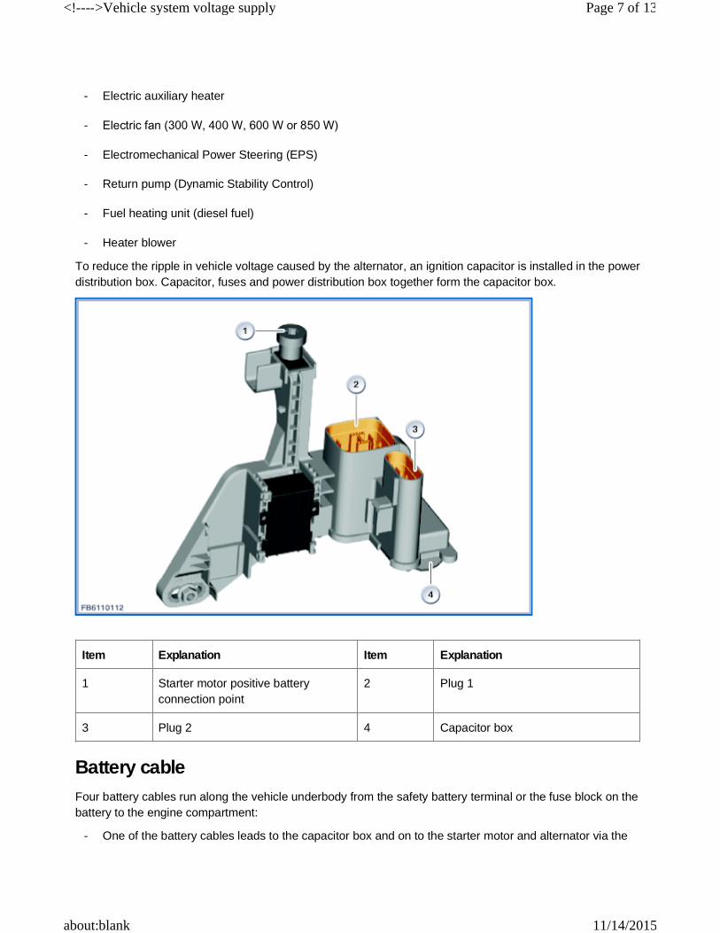
To reduce the ripple in vehicle voltage caused by the alternator, an ignition capacitor is installed in the power distribution box. Capacitor, fuses and power distribution box together form the capacitor box.
Battery cableFour battery cables run along the vehicle underbody from the safety battery terminal or the fuse block on the battery to the engine compartment:
- Electric auxiliary heater
- Electric fan (300 W, 400 W, 600 W or 850 W)
- Electromechanical Power Steering (EPS)
- Return pump (Dynamic Stability Control)
- Fuel heating unit (diesel fuel)
- Heater blower
Item Explanation Item Explanation
1 Starter motor positive battery connection point
2 Plug 1
3 Plug 2 4 Capacitor box
- One of the battery cables leads to the capacitor box and on to the starter motor and alternator via the
Page 7 of 13<!---->Vehicle system voltage supply
11/14/2015about:blank
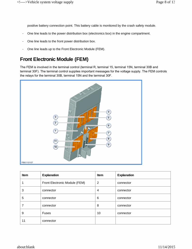
Front Electronic Module (FEM)The FEM is involved in the terminal control (terminal R, terminal 15, terminal 15N, terminal 30B and terminal 30F). The terminal control supplies important messages for the voltage supply. The FEM controls the relays for the terminal 30B, terminal 15N and the terminal 30F.
positive battery connection point. This battery cable is monitored by the crash safety module.
- One line leads to the power distribution box (electronics box) in the engine compartment.
- One line leads to the front power distribution box.
- One line leads up to the Front Electronic Module (FEM).
Item Explanation Item Explanation
1 Front Electronic Module (FEM) 2 connector
3 connector 4 connector
5 connector 6 connector
7 connector 8 connector
9 Fuses 10 connector
11 connector
Page 8 of 13<!---->Vehicle system voltage supply
11/14/2015about:blank
The bi-stable relays of the terminal 30F are activated in the following cases:
The following relays are located in the FEM:
Located in the same hardware (housing) as the FEM is the central gateway module (ZGM). The ZGM monitors the different bus systems (sleeping and waking up).
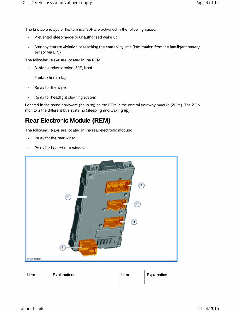
Rear Electronic Module (REM)The following relays are located in the rear electronic module:
- Prevented sleep mode or unauthorised wake up.
- Standby current violation or reaching the startability limit (information from the intelligent battery sensor via LIN).
- Bi-stable relay terminal 30F, front
- Fanfare horn relay
- Relay for the wiper
- Relay for headlight cleaning system
- Relay for the rear wiper
- Relay for heated rear window
Item Explanation Item Explanation
Page 9 of 13<!---->Vehicle system voltage supply
11/14/2015about:blank
DC/DC converter for providing support during an engine startDepending on equipment levels, vehicles with automatic engine start-stop function (MSA) may have a DC/DC converter installed to support the voltage supply when starting the engine. The DC/DC converter (180 W) is installed in the rear luggage compartment floor.The headunit is supported during engine start with the DC/DC converter.
System functionsThe following system function for voltage supply is described:
See also the following functional descriptions: Power management, Battery and IBS.
Terminal control (terminal 15N, terminal 30B and terminal 30F)Terminal 15N, terminal 30B and terminal 30F are switched terminals that provide the voltage supply for control units and components in the vehicle electrical system. The switched terminals enable optimisation of the energy consumption in normal operation, in the stationary mode (standby current) or in the event of faults.Terminal 15NTerminal 15N is used for the voltage supply of control units and components that are required for ”Ignition on”. Terminal 15N is activated together with the logical terminal 15 by activating the start/stop button. Terminal 15N is switched off with an after-running period of 5 s after switching off the logical terminal 15.Terminal 30BTerminal 30B provides the voltage supply for control units and components that in normal operation are required when the driver is present. The terminal 30B is activated by the FEM. Terminal 30B is activated in the following events:
1 Rear Electronic Module (FEM) 2 connector
3 connector 4 connector
5 connector
- Terminal control (terminal 15N, terminal 30B and terminal 30F)
- Unlocking, locking for securing the vehicle.
- Changing a door contact (driver's side front or rear, passenger's side front or rear).
- Changing the tailgate contact switch or operating the tailgate button.
- Changing the rear window contact switch or operating the rear window button.
- Changing the engine compartment lid contact switch.
- Operating the START‐STOP button.
- Operation of the interior light button.
Page 10 of 13<!---->Vehicle system voltage supply
11/14/2015about:blank
Terminal 30B is switched off with an after-running period that depends on the state:
The after-running period of terminal. 30B can be extended at the request of auxiliary consumer units. The number of extensions to the terminal 30B after-running period and the maximum duration of the terminal 30B after-running period is determined for each auxiliary consumer:
- Combox request.
State After-running period
Unlocked vehicle or opened tailgate.For vehicles with the following optional equipment: 633, 639, 644 or 6NB.
12 min30 mins.
After wake up by the Combox 3 mins.
Deadlocked vehicle and closed tailgate 3 mins.
Reaching the startability limit 3 mins.
Active transport mode 3 mins.
After sending the power-down command 10 s
Auxiliary consumers Maximum extension time
Maximum number of extensions
Headunit: Entertainment (radio, audio mode or video mode). 30 mins.
Combox: Telephone, telematics service. 10 mins.
Integrated automatic heating / air conditioning system: Residual heat function.
15 mins. 1
Integrated automatic heating / air conditioning system: Auxiliary heater function or independent ventilation function.
45 mins. 2
Instrument panel: Query of the coolant temperature. 5 mins. 1
After-run of the Rear Seat Entertainment. 30 mins.
Engine electronics: Tank leak diagnosis or electric fan after-run.
15 mins. 1
Engine electronics: Electric coolant pump after-run. 10 mins. 1
Electrical machine electronics (hybrid car): After-run of the 15 mins. 1
Page 11 of 13<!---->Vehicle system voltage supply
11/14/2015about:blank
Terminal 30FTerminal 30F provides the voltage supply for control units and components that in the normal operation require the terminal 30 but can be switched off in the event of faults. The terminal 30F is activated by the FEM. In the event of a fault, terminal 30F is reset. If the fault persists, this is followed by a shutdown.
The following faults lead to a reset or shutdown of terminal 30F:
Terminal 30F is not reset or switched off in the following circumstances:
For vehicles with active transport mode, terminal 30F is switched off 1 min. after switch-off of the terminal 30B.Terminal 30F is reactivated together with terminal 30B.
Notes for Service department
General notes
Notice! Charging and trickle charging of the battery.The battery may only be recharged using a BMW Group-approved charger at a constant charging voltage of 14.8 V. If possible, the battery temperature should be between 15 °C and 25 °C during charging. Under these preconditions, the battery is adequately charged when the charge current drops below 2.5 amps. If the battery is recharged at low temperatures, the charging procedure should not be ended until the charge current drops below 1.5 A. If the battery is to be charged while it is still installed, it must be charges using the jump start terminal points. Only then can you be sure that charging is correctly recognised by the vehicle electronics on vehicles with an intelligent battery sensor (IBS). If the battery is charged directly at the battery
- Parking light, side lights or hazard warning flashers ON.
- Manual or automatic emergency call active.
- Power window relay fault detected.
Page 12 of 13<!---->Vehicle system voltage supply
11/14/2015about:blank
terminals, this can lead to a misinterpretation of the battery condition and even unwanted Check Control messages, false entries or functional limitations. The cigarette lighter gets his voltage supply by the front power distribution box via the switched terminal 30B. After terminal 30B off, the relay de-energises. This means that a trickle charger connected at the cigarette lighter would be disconnected from the battery. Only charge the battery via the jump start terminal point.
Notice! Trickle charging of the battery for stored or stationary vehiclesIn the case of stored or stationary vehicles the battery must be recharged at regular intervals in order to avoid a total discharge and thus damage. See the following document: Battery charging calendar and battery tag.
Notice! Determining the state of charge after replacement of the IBS or the batteryAfter replacement of the battery and registration of the battery exchange or after replacement of the intelligent battery sensor (IBS) the vehicle must be in rest state for at least 3 hours: Only then can the new state of charge be determined by open-circuit voltage measurement.
Diagnosis instruction
Energy diagnosisA breakdown due to a flat battery or problems in the vehicle electrical system can have wide variety of causes. In most cases, the cause does not lie with the battery itself. For this reason, battery replacement will only rarely provide a sustained solution to the problem. Instead, systematic diagnosis of the source of fault is needed. Faults are often no longer present when the vehicle comes to the workshop. This is why data stored in the vehicle is the basis for fault diagnosis. Information on the battery condition as well as functional processes in the various bus systems are stored in the corresponding control units. This information can be called up and evaluated by the BMW diagnosis system. The BMW diagnosis system has a procedure for this. The procedure for energy diagnosis reads all the relevant data from the corresponding control units.
Notice! Register battery replacementAfter installing a new battery, the service function 'Register battery replacement' should be run. The battery replacement has to be registered in order to tell the power management system that a new battery has been installed in the vehicle. If the battery replacement is not registered, the power management will not function properly, with the result that Check Control messages may be displayed and functions limited by individual electrical consumers being switched off or having their power consumption reduced, for example.
Notes on encoding/programmingBattery type and battery capacity are encoded in the Front Electronic Module (FEM). The data can be read out using the BMW diagnosis system.
We can assume no liability for printing errors or inaccuracies in this document and reserve the right to introduce technical modifications at any time.