JSL 1 Fuel Cell Current Ripple Reduction with Active Control Technique Presented by Dr. Jih-Sheng (Jason) Lai Virginia Polytechnic Institute and State University Future Energy Electronics Center January 27 – 28, 2005 SECA Core Technology Program Review Meeting Tampa, Florida DOE SECA Project #: DE-FC26-02NT41567 Program Manager: Don Collins of NETL JSL 2 Outline 1. Review of V6 DC-DC converter 2. Prototype Development 3. Current Ripple Reduction 4. Summary of V6 Converter Prototype 5. Accomplishments and Future Work
Transcript
JSL1
Fuel Cell Current Ripple Reduction with Active Control Technique
Presented byDr. Jih-Sheng (Jason) Lai
Virginia Polytechnic Institute and State UniversityFuture Energy Electronics Center
January 27 – 28, 2005SECA Core Technology Program Review Meeting
Tampa, Florida
DOE SECA Project #: DE-FC26-02NT41567Program Manager: Don Collins of NETL
JSL2
Outline
1. Review of V6 DC-DC converter 2. Prototype Development3. Current Ripple Reduction4. Summary of V6 Converter Prototype5. Accomplishments and Future Work
JSL3
Block Diagram of the SOFC Power Plant
• Fuel cell output or converter input is low-voltage DC with a wide-range variation
• Plant output is high-voltage ac• Multiple-stage power conversions including
isolation are needed
DC-ACLF-HF
AC-ACLV-HV
AC-DCHV-HV
DC-ACHV-HV
DC-ACInverter
+Filter
SOFCAC-DC
Rectifier+
FilterVin
+
–
+
–
BridgeConverter
HFXformer
SECA DC/DC converter
400 V 120/240V
JSL4
Major Issues Associated with the DC/DC Converter
• Cost• Efficiency• Reliability• Ripple current• Transient response along with auxiliary
energy storage requirement• Communication with fuel cell controller• Electromagnetic interference (EMI) emission
JSL5
Virginia Tech Approaches
• Efficiency improvement to reduce fuel consumption
• V6 multiphase control to reduce passive components for cost reduction
• Ripple current elimination to reduce size of fuel cell stack
• Soft start and current control to reduce the inrush current so as to improve reliability
• Soft switching to reduce EMI
JSL6
State-of-the-Art Full-Bridge Converter
1 : n
HF ACXformer
Rectifier+LC filter
Act
ive
Load
Sol
id-O
xide
Fue
l Cel
l
Full-bridge converter
20V>250A
400V5 kW
JSL7
Full-Bridge Converter with Paralleled Devices to Achieve the Desired Efficiency
Load6x 6x
• With 6 devices in parallel, the two-leg converter can barely achieve 95% efficiency
• Problems are additional losses in parasitic components, voltage clamp, interconnects, filter inductor, transformer, diodes, etc.
Voltage clampSol
id-O
xide
Fue
l Cel
l20V250A
JSL8
Circuit Diagram of the Proposed V6 Converter
Sol
id-O
xide
Fue
l Cel
l
Act
ive
Load
Rectifier+LC filterSix-phase bridge converter
HF ACXformer
JSL9
Key Features of the V6 Converter
• Double output voltage reduce turns ratio and associated leakage inductance
• No overshoot and ringing on primary side device voltage
• DC link inductor current ripple elimination cost and size reduction on inductor
• Secondary voltage overshoot reduction cost and size reduction with elimination of voltage clamping
• Significant EMI reduction cost reduction on EMI filter• Soft switching over a wide load range• High efficiency ~97%• Low device temperature High reliability
JSL10
Efficiency Measurement Results
80%82%84%86%88%90%92%94%96%98%
100%
0 1000 2000 3000 4000Output power (W)
Experimental data and trend line
• Measurement error: within 1%• Heat sink temperature rise:
<20°C at 2kW with natural convection
Effi
cien
cy
75%
80%
85%
90%
95%
100%
0 500 1000 1500 2000 2500Output Power (W)
Effic
ienc
y
Phase-II V6-Converter Efficiency (calibrated)
Phase-I Efficiency Measured Results
JSL11
Waveform Comparison between Full-Bridge and V6 Converters
Full Bridge Converter V6 Converter
iL
iLvd
vd
• Secondary inductor current is ripple-less; and in principle, no dc link inductor is needed
• Secondary voltage swing is eliminated with <40% voltage overshoot as compared to 250%
JSL12
Schematic Circuit Diagrams
Power boardGate drive board
Control boardDigital board
Interface board
JSL13
Photographs of V6-Converter Together with DC-AC Inverter Prototype
Front View Rear View
ConverterInverter
JSL14
Current Ripple Issues with DC-AC Inverter Load
Lf
Cf RA
BVdc
+
–
Sap
San Sbn
Sbp
Vo
+
–
60Hz
120Hz
• Current Ripple Propagates from AC Load back to DC side• With rectification, ripple frequency is 120 Hz for 60 Hz systems• Low-frequency ripple is difficult to be filtered unless capacitor is
large enough
AC filter LC
High-sidecap.
DC-DCconverter
120Hz
FuelCell
JSL15
AC Current Ripple Problems• Inverter AC current ripple propagates back to fuel
cell• Fuel cell requires a higher current handling
capability Cost penalty to fuel cell stack• Ripple current can cause hysteresis losses and
subsequently more fuel consumption Costpenalty to fuel consumption
• State-of-the-art solutions are adding more capacitors or adding an external active filters Size and cost penalty
• Virginia Tech solution is to use existing V6 converter with active ripple cancellation technique to eliminate the ripple No penalty
JSL16
Circuit Model for AC Current Ripple
N:1Iin
Vin Iload
Rs Lf
Vdc+
–
Ip Is
iin/N
iload
N2Rs Lfip/N is
DC Model
AC Ripple ModelCin/N2
N2RCin
CinRCin
Cf
RCf
Cf
RCf
DC/DCConverterVin
Rs Lf
IloadCin
RCinCf
RCf
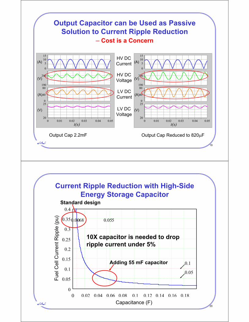
JSL17
Benchmark DC/DC Converter Parameters for Ripple Study
10X capacitor is needed to drop ripple current under 5%
JSL21
Experimental Current Ripples without Adding Capacitors or Controls
Input Voltage (20V/div) Input Current (10A/div)
AC Load Voltage (200V/div)AC Load Current (5A/div)
5ms/div
More than 35% ripple current at the input
JSL22
Current Ripple Under Dynamic Condition without Adding Capacitors
Fuel Cell Current Ripple is 35% plus Overshoot
Ifc
Vfc
iac
Fuel Cell Voltage (10V/div)
Fuel Cell Current (10A/div)
DC Link Current (25A/div)
AC Load Current (10A/div)
20ms/div
Id-LV
JSL23
AC Load Transient Response for Fuel Cell with 53-mF Added Capacitors
Fuel Cell Current Ripple is 5% plus Overshoot
VfcFuel Cell Voltage (10V/div)
Fuel Cell Current (20A/div)
DC Link Current (25A/div)
AC Load Current (10A/div)20ms/div
Ifc
iac
Icap
Id-LV
JSL24
Experiment with Open-Loop and with only Voltage Loop Control
No improvement on current ripple reduction with voltage loop control
DC bus voltage (100V/div)
Fuel cell voltage (10V/div)
Fuel cell current (20A/div)
DC bus current (10A/div)
(a) Open loop (b) With voltage loop control
t (5ms/div)
JSL25
Virginia Tech Solution to Ripple Reduction
vref +–Rv2Cv1Cv2
Rv1
Hv
vsense
Vo
+RL
Gvc
+–
Vm
PWMd
Lf
Cf
VdiLf
+–
Rcf+–Ri2Ci1
Hi
iref
Ri1
isenseCi2
Gic Vd = dVin
Adding a current loop to regulate the output current
JSL26
Fuel Cell Current Ripple Reduction with the Proposed Active Control TechniqueFuel Cell Current Ripple is Reduced to 2%
Input Voltage
Input Current
Output Current
Output Voltage
JSL27
Summary of V6 DC-DC Converter Prototype
• High efficiency with a wide-range soft switching: 97%• Cost reduction by cutting down passive components
– Output inductor filter reduction with three-phase interleaved control: 6X
– Input high frequency capacitor reduction: 6X– Output capacitor reduction with active ripple reduction: 10X
• Reliability enhancement– No devices in parallel– Soft-start control to limit output voltage overshoot – Current loop control to limit fuel cell inrush currents
• Significance to SECA Program and SOFC design – Stack size reduction by efficient power conversion and ripple
reduction: 20%– Inrush current reduction for reliability enhancement
JSL28
Prototype and Production Cost Estimate for the 5-kW V6 DC-DC Converter