FC Workshop 2015 Fuel cell systems for aircraft applications S. Flade, T. Stephan, C. Werner, L. Busemeyer, J. Schirmer & J. Kallo German Aerospace Center - Institute of Engineering Thermodynamics University of Ulm - Instiute of Energy Conversion and Energy Storage Lampoldshausen, 15.09.2015
Transcript
FC Workshop 2015
Fuel cell systems for aircraft applications
S. Flade, T. Stephan, C. Werner, L. Busemeyer, J. Schirmer & J. Kallo
German Aerospace Center - Institute of Engineering ThermodynamicsUniversity of Ulm - Instiute of Energy Conversion and Energy Storage
Lampoldshausen, 15.09.2015
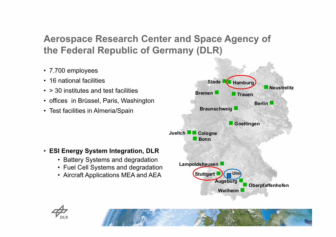
Aerospace Research Center and Space Agency ofthe Federal Republic of Germany (DLR)
• 7.700 employees• 16 national facilities• > 30 institutes and test facilities• offices in Brüssel, Paris, Washington• Test facilities in Almeria/Spain
• ESI Energy System Integration, DLR• Battery Systems and degradation• Fuel Cell Systems and degradation• Aircraft Applications MEA and AEA
Cologne
Oberpfaffenhofen
Braunschweig
Goettingen
Berlin
Bonn
Neustrelitz
Weilheim
Bremen Trauen
Lampoldshausen
Stuttgart
Stade
Augsburg
Hamburg
Juelich
Ulm
University of Ulm –Institute of Energy Conversion and Energy Storage
Department of Hybrid Concepts• Power Electronic Hardware, Controls and
FC/Battery Power Management Systems
Department of Propulsion Research• High power E-Machines, Generators
Applications: Aircraft applications, ….
Hardware/Teststand: • ICE-Battery-E-Machine Hybrid up to 250kW• Hydrogen infrastructure• Low Pressure and Temperature chamber for
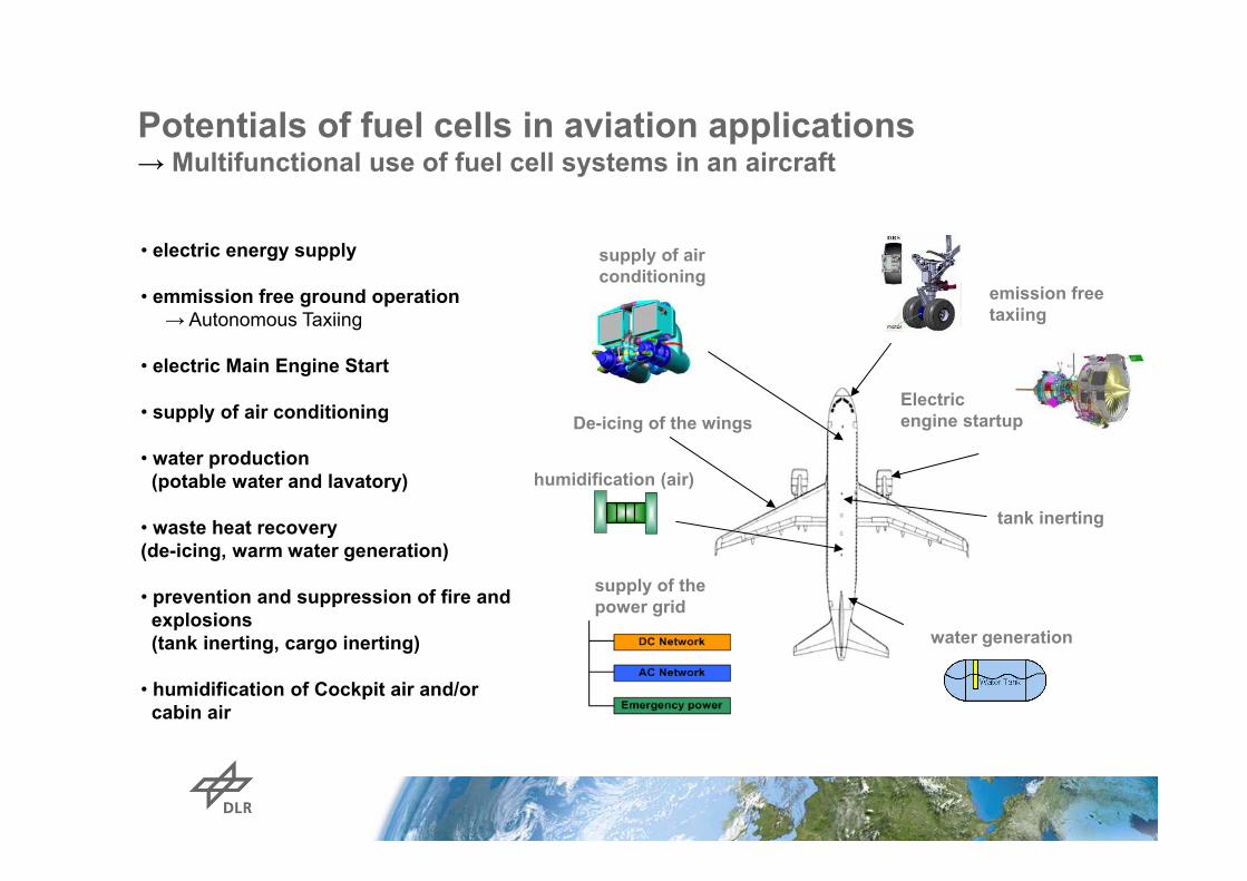
• waste heat recovery(de-icing, warm water generation)
• prevention and suppression of fire and explosions(tank inerting, cargo inerting)
• humidification of Cockpit air and/orcabin air
tank inerting
water generation
supply of thepower grid
De-icing of the wings
humidification (air)
emission freetaxiing
Electricengine startup
supply of airconditioning
Potentials of fuel cells in aviation applications→ Multifunctional use of fuel cell systems in an aircraft
Fuel Cell Aircraft and Airport Applications at DLRInstitute of Engineering Thermodynamics
Fuel Cell TechnologyDevelopment Platform
Electric Energy, ODA, Water Source (MFFC)Energy Source for Emission Free Taxi
Modular Hybrid Development PlatformEASA CS.22 and CS.23.Light
Flying Testrig for Fuel Cells and Hybrids,Emission Free Propulsionfor UAV and General Aviation(4‐6 Pax or 200 kg Payload)
Aircraft flight profile
Taxiing & Takeoff
Climb Landing & TaxiingCruise Descent
0,25bar < Pin_air < 1bar
)()(
)()1(
)(21,0
__
__
_
_
__
__
2
2
2
2
2
2
InInOHSatInIn
InInOHSatIn
InOHIn
InOH
ExhaustExhaustOHSatExhaustExhaust
ExhaustExhaustExhaustOHSatExhaustCathode TprHp
TprHpp
pwith
TprHppTprH
gasinlet cathode of pressurer Water vapo
gasexhaust cathode of Pressure
gasinlet cathode of Pressure
gasinlet cathode ofhumidity Relative
gasexhaust cathode ofhumidity Relative
_2
InOH
Exhaust
In
In
Exhaust
p
p
p
rH
rH
gas exhaust cathode of eTemperatur
gas inlet cathode of eTemperatur
gas exhaust cathode of pressure vapor Saturation
gas inlet cathode of pressure vapor Saturation
__
__
2
2
Exhaust
In
ExhaustOHSat
InOHSat
T
T
p
p
Assumptions:• Pressure difference between cathode inlet and outlet is neglected• Water drag between cathode and anode is neglected• O2 – Concentration of cathode inlet gas is assumend to be 21 Vol.-%• Tin = TExhaust – 10K
Impact of feed gas humidification to the water manage-ment of a PEMFC under aviation relevant conditions
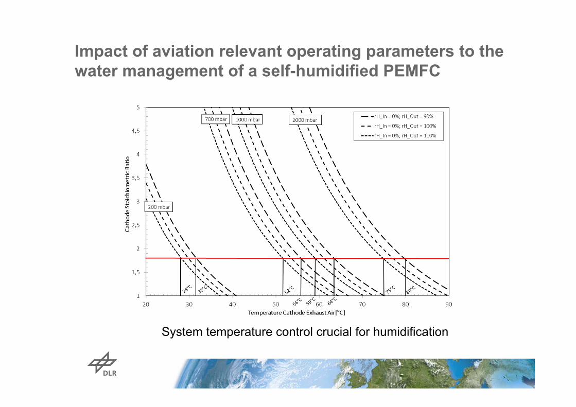
Impact of aviation relevant operating parameters to thewater management of a self-humidified PEMFC
System temperature control crucial for humidification
System build up:Fuel Cell Technology Transfer to Aircraft Application


![New York Tribune (New York, NY) 1907-06-23 [p ]...Imported Semi-flade Robes ALMOST HALFUSUAL PRICES Embroidered Creme Batiste Robes. g^SiS^SSJSS signs, trimmed with five rows of embroidery](https://static.documents.pub/doc/80x56/5fe34b7f2ffc0a26325e104d/new-york-tribune-new-york-ny-1907-06-23-p-imported-semi-flade-robes-almost.jpg)
