Fuel cells for distributed power: benefits, barriers and perspectives Commissioned by WWF, in co-operation with Fuel Cell Europe Authors: Dr. Martin Pehnt Institut für Energie- und Umweltforschung Heidelberg IFEU Wilckenstr. 3, D-69120 Heidelberg [email protected]Dr. Stephan Ramesohl Wuppertal Institut für Klima, Umwelt, Energie Postfach 10 04 80, D-42004 Wuppertal stephan.rame[email protected]
Transcript
Fuel cells fordistributed power:benefits, barriers and
perspectives
Commissioned by WWF, in co-operation with Fuel Cell Europe
Authors:Dr. Martin PehntInstitut für Energie- und UmweltforschungHeidelberg IFEUWilckenstr. 3, D-69120 [email protected]
Dr. Stephan RamesohlWuppertal Institut für Klima, Umwelt, EnergiePostfach 10 04 80, D-42004 [email protected]
Market introduction of stationary fuel cells IFEU, Wuppertal Institut
2
1 Content
1 CONTENT 2
2 SUMMARY 5
3 INTRODUCTION 11
3.1 Fuel cells as a disruptive technology? 11
3.2 Structure of this study 13
4 POTENTIAL ADVANTAGES OF STATIONARY FUEL CELLS 14
4.1 The efficiency advantage: Reduction of climate gas emissions andprimary energy demand through high electrical efficiency 14
4.2 Fuel switching: Using renewable primary energy carriers for fuelcells 20
4.2.1 Bio-based fuels 214.2.2 Renewable electricity: Fuel cells in a “Hydrogen Economy” 234.2.3 The transition to higher shares of renewables 24
4.3 Low criteria pollutant emissions 25
4.4 Noise, vibration, space 26
4.5 Heat levels suitable for industrial and cooling applications 27
4.6 Dynamic load response 28
4.7 High power to heat ratio 29
4.8 Synergies to mobile sector 29
4.9 New business segments for IPP, small scale CHP, gas suppliers andenergy services 30
4.9.1 Premium power 304.9.2 Domestic CHP as new market opportunity 324.9.3 New energy services for the household customers 324.9.4 Market opportunities for gas utilities 334.9.5 New options for supply of backup power 34
4.10 Possibility of ‚simpler’ CO2 storage 36
4.11 Opportunity to de-block current ignorance vis-à-vis CHP 38
Market introduction of stationary fuel cells IFEU, Wuppertal Institut
3
4.12 Further advantages common to all distributed generationtechnologies 39
4.12.1 Reduced transmission/distribution losses and less required grid capacity39
4.12.2 Reduced vulnerability of the energy system 394.12.3 Modularity of the system 40
5 BARRIERS, CHALLENGES AND OPEN QUESTIONS 41
5.1 Cost 415.1.1 Cost targets 425.1.2 Where are we now? 44
5.2 Decreasing future heat demand in households and buildings 45
5.3 Structural changes in traditional heat markets 46
5.4 Growing ecological competition from renewable energy sources 48
5.5 International Codes and Standards, safety regulation 49
5.6 Investors waiting 50
5.7 Technical challenges 51
5.8 Availability of Balance-of-Plant (periphery) components 52
5.9 Technical aspects of grid connection 53
5.10 Time gap between Kyoto and readiness for marketing 54
5.11 Further barriers common to all CHP systems 555.11.1 Grid connection and systems integration barriers 565.11.2 Market access and contracting 565.11.3 Financing and price structures in liberalised markets 575.11.4 Integration and coordination of the regulatory framework 575.11.5 Dependency on natural gas as the major energy carrier 58
6 MARKET PERSPECTIVES AND STRATEGIC IMPLICATIONS 59
6.1 Market surveys 59
6.2 Example: The UNEP scenario and its consequences 626.2.1 How likely is the UNEP scenario? 636.2.2 GHG reduction in the UNEP scenario 64
6.3 Long-term market prospects and future challenges 666.3.1 General framework conditions 666.3.2 Techno-economic factors 68
Market introduction of stationary fuel cells IFEU, Wuppertal Institut
4
6.3.3Socio-economic and institutional prerequisites for functioning fuel cellmarkets 686.3.4 Conclusion: future market prospects result from variousinterdependencies 69
6.4 Incentives and Policy Framework 71
7 STATIONARY FUEL CELLS: TRYING TO SUMMARISE A COMPLEXTOPIC 74
8 ABBREVIATIONS 79
9 REFERENCES 80
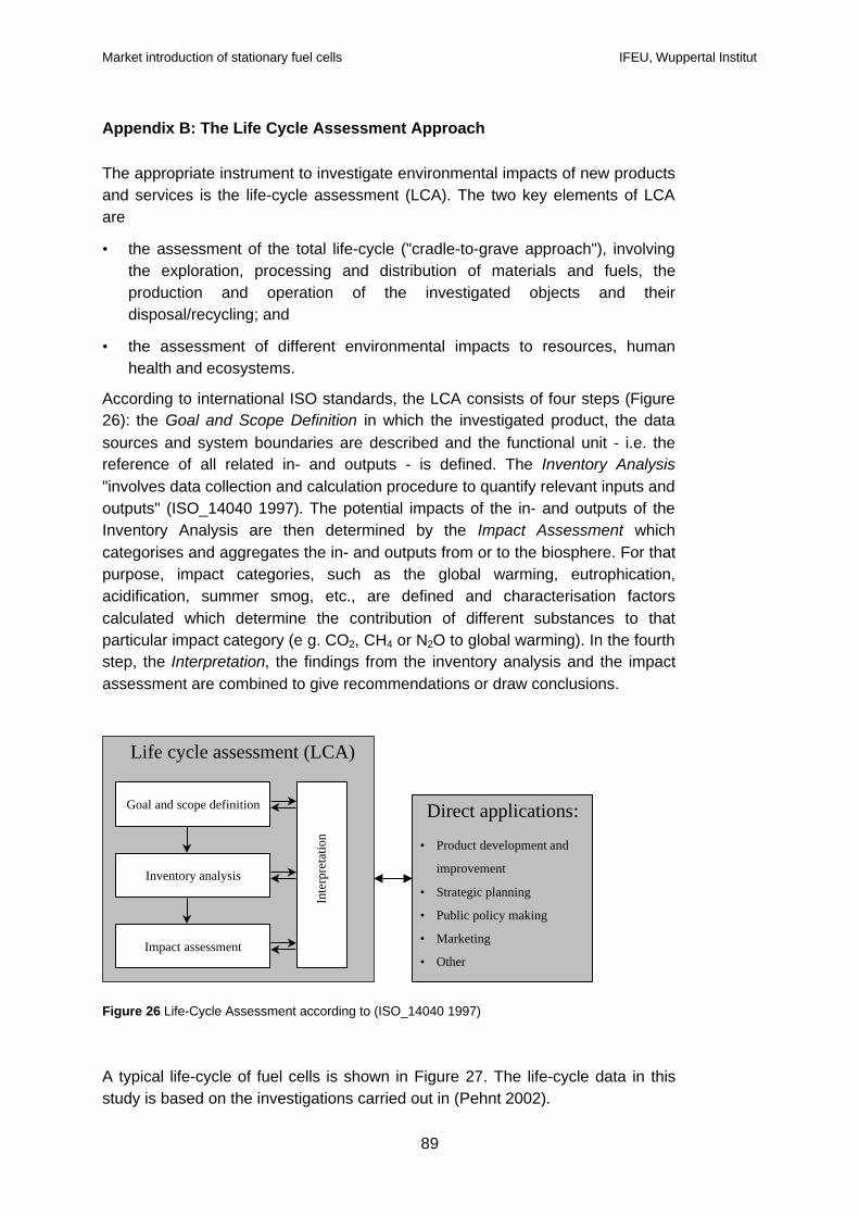
APPENDIX A: FUEL CELLS: A SHORT INTRODUCTION 84
APPENDIX B: THE LIFE CYCLE ASSESSMENT APPROACH 89
Market introduction of stationary fuel cells IFEU, Wuppertal Institut
5
2. Fuel cells for distributed power: benefits, barriers and perspectives –Executive Summary
Fuel cells are often portrayed as the answer to the world’s pressing need forclean, efficient power. They are also seen as a key component in a future»hydrogen economy« that will substantially reduce or eliminate pollutant andgreenhouse gas emissions associated with current power generation andtransport. However, questions about the technology still remain: to what degreeare the expectations surrounding fuel cells realistic and can they deliver whatthey promise?
The following report summary, which focuses on stationary fuel cells, addressesthese questions. Stationary fuel cells are the type of fuel cells used in buildings orpower generation parks. They will most likely enter the market before automotivefuel cells for technical and cost reasons.
What are fuel cells?
A fuel cell combines hydrogen with oxygen (from air) in a chemical reaction,producing water, electricity and heat. Fuel cells do not “burn” the fuel, theconversion takes place electrochemically without combustion. Fuelled with purehydrogen, they produce zero emissions of pollutant and greenhouse gases at thelocation of the power plant. Where hydrocarbon fuels such as natural gas areused a “fuel reformer” (or “fuel processor”) is required to extract the hydrogen. Inthis case the production of hydrogen is connected to greenhouse gas emissionsand - very low - emissions of pollutants. However, the production and supply ofthe fuel also causes emissions. Therefore the future role of fuel cells and theirenvironmental benefits have to be assessed through life-cycle and energysystems analyses.
Where does the fuel come from?
Hydrogen, the most common chemical element, is not naturally available inuseful quantities in its pure form. The process of separating hydrogen fromchemical compounds like water, natural gas and other carriers always requiresenergy. The method used to produce this energy determines the environmentalimpact and economic prospects of power generation in fuel cells.
The cleanest and most environmentally friendly way to produce hydrogen isthrough renewable energy. Electricity from wind and solar power can be used toproduce hydrogen by electrolysis as one component of the ultimate long-termvision of a fully renewable based energy system. Unfortunately the conversion ofrenewable electricity into hydrogen and then back into electricity is associatedwith significant energy losses and additional costs.
For stationary fuel cell applications, this solar hydrogen path makes sense onlywith a high share of renewables in the electricity generation system, because inthese systems, a storage medium for electricity generated from intermittentrenewable sources such as wind or solar power is required. In large electricity
Market introduction of stationary fuel cells IFEU, Wuppertal Institut
6
grids, stationary fuel cells run with solar hydrogen are thus a longterm optionwhereas island and remote applications could offer an early niche market.
Fuel cells can also operate on biomass-derived fuels. In bio fuel applications, allcombined heat and power (CHP) technologies have very low greenhouse gas(GHG) emissions. The advantage that fuel cells deliver in this application is themore efficient use of limited – and often costly – biomass resources. Due to thehigh capital cost and the technically challenging integration of still prematurecomponents like gasification, gas processing and fuel cells, bio-based fuel cellsare a long-term option for 2020 and beyond. Biogas produced from manure orsewage gas could, however, provide an attractive early market.
Fossil fuels and nuclear power can also be used to produce hydrogen. However,fossil fuels generate greenhouse gas emissions and nuclear power causes manyproblems such as waste disposal and safety risks. Due to extremely high capitalcost, low electrical efficiencies and prevailing technical problems, the use of coalgas in fuel cells with subsequent CO2 storage is not seen as a successful climatestrategy for the next decades. In addition, carbon disposal remains an openissue, as the safe storage of CO2 cannot be guaranteed presently.
The cleanest conventional hydrocarbon fuel to be used in fuel cells is natural gas.It has the lowest greenhouse gas emissions per energy unit of all fossil fuels.While natural gas based CHP is not considered a sustainable energy source assuch, it does represent an efficient way of economising the inevitable fossilenergy input during a transition period to a renewable energy supply system.Moreover, natural gas can bridge the gap between our fossil system and a futuresystem because it offers the possibility to gradually switch to renewably producedhydrogen (or biogas/synthesis gas). This can then be fed into the pipelinedistribution system and ultimately replace natural gas as a fuel. Therefore thisreport focuses on the environmental benefits of natural gas powered fuel cells incomparison with conventional technologies.
Can fuel cells help to reduce CO2 and pollutant emissions?
Fuel cells will enter the market too late to make a significant contribution to theKyoto commitments for 2008/2012. In the mid-to-long-term, however, stationaryfuel cells have a high potential for environmentally friendly energy conversion:they offer high electrical efficiencies and extremely low (fuel: hydrocarbon) oreven zero (fuel: hydrogen) pollutant emissions. The potentially high electricalefficiency of fuel cell power plants is one of the major advantages of thesesystems. For each power range, fuel cells will offer higher efficiencies than theconventional competitors.
For instance, compared to separate electricity production in central powerstations with a coal biased electricity mix (such as the German electricity mix) oreven compared to a lignite power plant, GHG reductions above 50% can beachieved with fuel cells powered by natural gas. In a life cycle assessment, eachkWh of electricity produced by a fuel cell will reduce the related CO2 emissions byat least 40% compared to the existing fossil power generation in the current 15
Market introduction of stationary fuel cells IFEU, Wuppertal Institut
7
countries of the European Union (EU-15) and 20 to 30% compared to modernseparate production (modern gas plants and boilers). However, compared tocompeting CHP technologies such as Stirling and reciprocating engines or gasturbines, only low GHG reductions, if any, can be achieved. This is mainly due tolower thermal efficiencies of fuel cells and it underlines the necessity to optimisetheir total/thermal efficiency. Fuel cells powered by renewable hydrogen willreduce emissions almost 100% compared to fossil options.
In order to estimate the total potential emission reductions achievable in the EU-15 until 2020 this report adopts a market introduction scenario of the UnitedNations Environment Programme (UNEP). The UNEP projections envisage some27 GW of installed fuel cell capacity in OECD Europe for the year 2020, whichrepresents an optimistic starting point for the analysis.
Under the assumption that fuel cells displace the average EU electricity and heatmix (excluding nuclear and hydropower), the estimated GHG reduction amountsto 55.4 Mt/a CO2 equivalents, which equals 1.3 % of the European GHGemissions in 1990, or 22.3 Mt/a CO2 eq., if the electricity mix includes nuclearand hydropower.
These reductions are the result of four separate mechanisms: the reduction dueto a fuel shift (oil and coal to gas), an efficiency increase from average toadvanced power plants and heating systems, an efficiency increase fromseparate to combined production, and an efficiency increase from modern CHPto fuel cells. The first three would also be realised based on conventional CHP sothat only the last effect can be fully attributed to fuel cell technology. If oneconsiders the coming need to replace power generation capacity in Europe, acomparison of fuel cells to modern separate production (i.e. a natural gascombined cycle plant and a gas condensing boiler) is required. In thiscomparison a GHG reduction of 14 Mt/a CO2 eq. would be achieved.
Under the assumption that CHP is developing quickly we must also compare fuelcells with competing CHP technologies, e.g. the reciprocating engine in districtheating CHP or the gas turbine in industrial CHP applications. In this instance,and using the UNEP scenario assumption, a GHG reduction in the order of 5Mt/a CO2 eq. would be achieved.
In addition to climate change mitigation, fuel cells offer great advantages withrespect to environmental impacts that are caused by criteria pollutants, such asacidification (mainly caused by NOx and SO2), eutrophication, summer smog orcarcinogenic substances. Compared to these impacts, fuel cell power plants yieldreductions of pollutants ranging from 40% (summer smog) to almost 90%(eutrophication) depending on the baseline technologies. The EU 15’s emissionssituation differs from the EU accession countries. Because pollutant emissionlevels are much higher in central and eastern Europe, the introduction of fuelcells would lower emission levels significantly.
Market introduction of stationary fuel cells IFEU, Wuppertal Institut
8
What are other benefits?
Fuel cells offer several technical advantages, such as modularity, good partialload characteristics, dynamic response or high heat levels which are favourablefor industrial and cooling applications. In addition, advantages that are commonto all cogeneration technologies, such as reduced transmission losses, reductionof required grid capacity, etc. can be made accessible. Moreover, fuel cells mightopen up a completely new market segment: that of domestic CHP (MicroCHP)with small-scale systems below 10 kW, which would provide heat and power forsingle and multi-family houses. Considering the large replacement market for gasheating boilers, a mass market for MicroCHP can be expected. In fact, mostmajor European heating systems manufacturers are currently active indeveloping domestic combined heat and power systems.
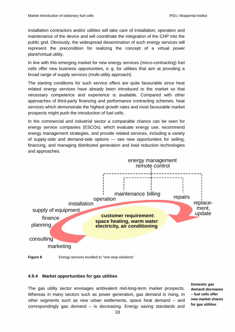
The key to the market success of fuel cell heating systems as seen as providinga “one-stop solution” complete energy service package to the customer. In linewith this emerging market for new energy services (micro-contracting), fuel cellsoffer new business opportunities, e.g. for utilities that aim to provide a broadrange of supply services (multi-utility approach). In this context, fuel cells providegas utilities with an opportunity to increase sales and compensate for adecreasing need for space heating – and thus domestic gas demand.
New applications might arise from grid-related operation of fuel cells that build onthe dynamic performance of electricity generation. Sophisticated concepts suchas the “virtual power plant” aim at the interconnection of a large number of fuelcells via communication technologies. This would enable central control andmanagement of the decentralised generating units, e.g. for the purpose of loadlevelling of intermittent power production. However, considerable technologicalobstacles need to be overcome.
What are the barriers to a broad market introduction of fuel cells?
As fuel cells have to succeed in an already competitive market, cost is seen asthe major market entry barrier. Stationary fuel cells are still between 2.5 to 20times more expensive than competing technologies, with the balance of plant(periphery) being responsible for a large share of total capital cost. The challengefor fuel cell development is to reconcile the often conflicting requirements of costreduction and performance improvement. For this reason, there is stillconsiderable uncertainty with respect to the size and time scale of the marketentry of stationary fuel cells. Today’s investments in CHP should not bepostponed, however, in order to wait for fuel cells. Conventional technologiesshould instead be used to establish CHP infrastructures that can be updated laterwith second generation fuel cell systems.
Traditional players in the heat market such as installation contractors play adecisive role in the dissemination of new heating technologies. They will need tobe fully prepared in time through information dissemination and professionaltraining in order for them to play an active role in the promotion of fuel cells CHPsystems.
Market introduction of stationary fuel cells IFEU, Wuppertal Institut
9
Certain barriers that may hinder a wide spread utilisation of stationary fuel cellsapply to all CHP applications and are not specific to fuel cells. Among these,easy grid connection is a key to market success of fuel cells. Today, however,current distribution grids are not designed for large-scale integration of distributedpower generators. All of the envisaged problems can be solved from a technicalpoint of view but institutional arrangements for a fair and discrimination-freeallocation of costs for upgrading, investment and management of grids are stilllacking.
In this context, the interconnection of mid to small scale CHP plants to the grid isoften hindered by restrictive conditions and complicated procedures. Problemsarise with regard to connection charges, determination of the point of connection,safety and liability issues. Most importantly, a standardised technical interfaceneeds to be established as do non-discriminatory rules for the allocation ofconnection costs that take into account possible positive effects of distributedgeneration on grid investments and transmission and distribution losses.
Regulatory regimes, however, still do not provide sufficient incentives for gridoperators to connect distributed generation plants, and conditions differ betweenmember states, regions and utilities. Often, connection charges lacktransparency and appear to exceed factual costs of the grid operator. Moreover,the administrative handling of CHP projects is delayed due to low priority for theutility.
For this reason, the introduction of distributed generation is strongly linked withthe controversial debate on the unbundling of power generation and networkoperation and the regulation of systems operators in order to assure a neutralstance towards independent CHP plants.
Closely related to the aspect of interconnection, new traders for renewable andCHP electricity can suffer from non-transparent and excessively high connectionfees and costs for stand-by and back-up power. Whereas grid use fees are ofless relevance for a single project under a priority dispatch scheme, themarketing of “green power” is strongly affected. This limits the possibility to sellCHP electricity at premium prices to specific market segments.
How to overcome the barriers?
There is still uncertainty surrounding the long-term development of the energypolicy framework. This hinders strategic investments into distributed generation.For this reason, long-term target setting by the EU and member states in terms ofdistributed generation integration would increase the reliability of marketprojections and investor confidence.
In parallel to the technical progress, therefore, a co-evolution of socio-economicand institutional prerequisites has to take place to pave the way for a smoothmarket introduction.
Especially during the first phases of market introduction, additional incentives willbe needed to close the cost gap with competing technology. Energy policy can
Market introduction of stationary fuel cells IFEU, Wuppertal Institut
10
provide direct incentives for early adopters, e.g. as investment subsidies, grants,tax deduction, etc.; stabilise market prospects for distributed power generation byenhancing market entries and competition together with a removal of barriers;and create general incentives for efficient and environmentally benign use ofenergy, e.g. energy and/or GHG taxes, emissions trading, air quality standards,noise pollution regulation, etc.
Conclusion
Fuel cells are a potentially important option among others that may contribute toincreased economic efficiency and environmental performance of Europe’senergy system. It is therefore critical that fuel cell policies be integrated into anoverall guiding strategy for the sustainable development of European energysystems which aims for efficient use of energy and the expansion of renewableenergy sources.
The transition from a fossil based system and its fully developed infrastructure toa “renewable hydrogen system” as an ultimate goal will take a long time. Duringthe transition, research and development as well as deployment in niche marketsand lead applications can pave the road.
It is important to make clear that these demonstration projects do not substitute,but supplement the development of rational use of energy and renewable energycarriers. The political and economic decisions for tomorrow’s power generationmust support the full range of climate friendly and sustainable technologies inorder to surmount the “fossil fuel age”. With natural gas as a bridging fuel, fuelcells will help to realise the renewable energy economy and a carbon free powersector.
Market introduction of stationary fuel cells IFEU, Wuppertal Institut
11
3 Introduction
One hundred years ago, the electro-chemist Wilhelm Ostwald presented hisvision of the 20th century as the century of electrochemical, combustion freeenergy conversion. In the age of coal, his credo ´no smoke, no soot´ seemedunrealistic. However, 70 years before Ostwald´s statement the British amateurchemist William Grove and the German Christian Friedrich Schönbein – the latterknown for discovering ozone – had already invented the fuel cell, a deviceconverting the energy of a fuel into electricity without any open flame. Onecentury later, we are much closer to Ostwald´s vision. Innovative energyconverting technologies with higher efficiencies and lower environmental impactswill generally play a key role in developing sustainability strategies for nationaland European energy systems.
3.1 Fuel cells as a disruptive technology?
In the past years, fuel cells have been considered frequently as an attractiveenergy converter. Fuel cells are an energy system with a high potential forenvironmentally-friendly energy conversion. Fuel cells convert the chemicalenergy of a fuel and oxygen continuously and electrochemically into electricalenergy (for details on the function of fuel cells see (Pehnt 2002) and Appendix A).The "secret" of fuel cells is the electrolyte that separates the two reactants, H2
and O2, to avoid an uncontrolled explosive reaction. Basically, the fuel cellconsists of a sandwich of layers which are placed around this central electrolyte:the anode at which the fuel is oxidised, the cathode at which the oxygen isreduced, and bipolar plates which feed the gases, collect the electrons, andconduct the reaction heat. Fuel cell stacks consist of many single cells connectedin series.
Fuel cells can be categorised according to the electrolyte material and,correspondingly, the required operating temperatures into low, medium and high-temperature applications (see Table 1 and Appendix A). Although the higheroperating temperatures of MCFC and SOFC result in decreasing thermodynamicefficiencies, the better kinetics as well as the option to use the high temperatureexhaust gas (e.g. in gas turbines) more than offset this efficiency reduction. Inaddition, high temperature fuel cells offer the advantage of internal reforming, i.e.the heat produced in the electrochemical reaction is simultaneously used forreforming natural gas or other fuels into hydrogen inside the stack, thusdecreasing the required cooling effort while efficiently using the heat. Also, high-temperature fuel cells have lower purity requirements of the fuel. Whereas AFCsare sensitive to CO2 and PEFC to CO impurities, CO2 acts in high-temperaturefuel cells as inert gas only, and CO can even be used as a fuel.
High potential forenvironmentallyfriendly conversion
Types of fuel cells
Market introduction of stationary fuel cells IFEU, Wuppertal Institut
12
Table 1: Types of fuel cells and main characteristics
AFC PEFC DMFC PAFC MCFC SOFC
Electrolyte KOH Protonconductingmembrane
Protonconductingmembrane
Phosphoricacid
Carbonate melt Y stabilisedZrO2
Temperature 60 - 90 °C 60 - 90 °C 80 - 130 °C 200 °C 650 °C 800 - 1000 °C
Ion OH- H+ H+ H+ CO32- O2-
?System, el (%)(natural gas)
30 * – 42 38 – 42 50 – 55,w/ ST > 55
30* – 55,w/ GT > 60
?System, el (%)(hydrogen)
38* – 50 47 – 50 n. a. n. a.
Favouredapplication
Space,military,portable
Mobile,portable, CHP
Mobile,portable
CHP CHP, CC CHP, CC
Power range(kWel)
2 – 200 50 – 10,000 200 – 100,000 2 – 100,000
Status Firstcommercialproduction
Prototypes,first
commercialproduction
Research Small seriesproduction(200 kWel)
Demonstration Demonstration
ST: Steam turbine; GT: Gas turbine; CHP: Combined Heat and Power Production; AFC: Alkaline Electrolyte FuelCell; PEFC: Polymer Electrolyte Membrane Fuel Cell; DMFC: Direct Methanol Fuel Cell; PAFC: Phosphoric AcidFuel Cell; MCFC: Molten Carbonate Fuel Cell; SOFC: Solid Oxide Fuel Cell n. a. not available * for MicroCHP
Fuel cells can be used in stationary and mobile applications. Depending on thetype of fuel cells, stationary applications include small residential, medium sizedcogeneration or large power plant applications. In the mobile sector, particularlylow-temperature fuel cells, can be used for heavy-duty and passenger vehicles,for trains, boats or auxiliary power units for air planes. Mobile applications alsoinclude portable low power systems for various uses (Pehnt 2002).
From an environmental point of view, the high efficiency can lead to a significantreduction of fossil fuel use and of greenhouse gas (GHG) emissions. In addition,the electrochemical nature of the reaction, the low temperature of the reformingreaction and the necessity to remove impurities in the fuel (such as sulfur) resultin extremely low local emissions – an important feature especially in denslypopulated and highly polluted areas. In vehicle applications, particularly at lowspeed, reductions in noise emissions are to be expected.
At the same time, however, the conventional technologies have been constantlyoptimised, creating a strong competition and lowering the margin for potentialbenefits of fuel cells. Consequently, the public perception of fuel cells differs. Thiscan be shown quite plainly with two quotations from the 24/2/2003 VDEW-Fuelcell Newsletter. It quotes Johannes van Bergen, president of the German„Bundesverband Kraft-Wärme-Kopplung“ (German Cogeneration Association):
„Die Brennstoffzelle im Haushalt braucht noch zehn bis 15 Jahre, wenn sie überhauptkommt. Die Euphorie, die hier mitunter herrscht, ist durch nichts gerechtfertigt. Was soll ander Brennstoffzelle besser sein als an den heutigen BHKW?“ (The fuel cell in domestic
Diverging publicperception of fuelcells
Applications
Market introduction of stationary fuel cells IFEU, Wuppertal Institut
13
applications will need some 10 to 15 years if it comes at all. The euphoria is not justified atall. Which aspects of fuel cells shall be better and in today’s reciprocal engines?“
In the same newsletter, Dietmar Kuhnt, CEO of the RWE AG is quoted saying:
“Fuel Cell Technology is predestined to make a major contribution to distributed power andheat production for generations to come. In Germany a market potential of up to 65 TWhannually is achievable by 2015. This is almost the yearly power consumption of Belgium.”
3.2 Structure of this study
In this short study, we will collect and bring forward arguments, potentialadvantages and barriers of stationary fuel cell applications. The study wascommissioned by the World Wide Fund for Nature and Fuel Cell Europe.
In chapter 4, we will analyse potential advantages of fuel cells in stationaryapplications, in chapter 5 the barriers hampering the implementation of fuel cellpower plants. Chapter 6 will try to synthesize the information from the precedingchapters, deriving strategic elements and giving hints to a possible future marketdevelopment of fuel cells.
It has to be noted that due to the limited time budget, some aspects can only betouched and not worked out in a detailed manner. Particularly, due to thecomplexity of the CHP debate today and the discussion on the EuropeanDirective, only advantages and barriers that are specific to fuel cells, and not toCHP as a whole, will be analysed.
Market introduction of stationary fuel cells IFEU, Wuppertal Institut
14
4 Potential advantages of stationary fuel cells
Advantages of stationary fuel cells can be determined on various levels (Figure1), from environmental and technical advantages to energy economic aspects. Inthe following sections, main potential advantages of fuel cells will be outlined andinvestigated with respect to correctness, feasibility, and implications.
• Opportunity to de-block current political and publicignorance vis-a-vis CHP
• Heat levels suitable to industrial and coolingapplications (HT-FC)
• Good partial load characteristics and dynamicresponse
• High power to heat ratio• Modularity• Lower maintainance costs due to less moving parts(durability)
• New business segments for gas, transmission andservice companies (electricity, contracting, gridsupport, backup/ premium power, domestic CHP,...)
• Increased reliability of distributed generation• Compensation for increasing shares of fluctuating
renewable energy sources • Reduced vulnerability of the energy system• Synergies to mobile sector (cost reduction, joint R&D, joint H2 supply , vehicle to grid,...)
• Higher efficiency => lower CO2 emissions andresource consumption
• Simple fuel switching (less C intensive, renewable), compatibility w/ H2 from renewable primary energy
• CO2 sequestration potential• Lower criteria pollutants• Less noise and vibration• Distributed generation => less transmissionlosses, less required grid capacity, etc.
Ecological Energy Economic
Technical Miscellaneous
Potential advantages of and drivers for stationary fuel cells
Figure 1 Potential advantages of fuel cells in stationary applications
4.1 The efficiency advantage: Reduction of climate gas emissions andprimary energy demand through high electrical efficiency
The potentially high electrical efficiency of fuel cell power plants is one of themajor advantages of these systems. For each power range, fuel cells will offerhigher efficiencies than the conventional competitors (Figure 2). It has to bementioned that for fuel cells, these numbers present target values whereas thedemonstration plants do not yet reach these numbers. For conventional systems,future optimisation potentials are also included in Figure 2 as the upperboundaries of the boxes.
Fuel cells offer highelectrical efficiencies
Market introduction of stationary fuel cells IFEU, Wuppertal Institut
15
0,01 0,1 1 10 100 1000
Electrical Power (MW)
0
10
20
30
40
50
60
70
80E
lect
rica
l Eff
icie
ncy
(%)
CombinedCycle
Gas turbine
Reciproc. engine
PEFCPAFC
SOFC, MCFC
SOFC, MCFC w/ gas turbine
SOFC
\projekte\wwf\Abb Elektr Wirkungsgrade
0,01 0,1 1 10 100 1000
Electrical Power (MW)
0
10
20
30
40
50
60
70
80E
lect
rica
l Eff
icie
ncy
(%)
CombinedCycle
Gas turbine
Reciproc. engine
PEFCPAFC
SOFC, MCFC
SOFC, MCFC w/ gas turbine
SOFC
\projekte\wwf\Abb Elektr Wirkungsgrade
Figure 2 Electrical efficiencies of various future stationary fuel cell systems and theircompetitors
Referring to natural gas as the dominant fuel cell fuel in a short and midtermperspective, PEFC in the low power range will reach electrical efficiencies in theorder of 28 to 33 %, in the long-term possibly up to 36 % for domestic systemsand 40 % in the 200 kWel range. The latter value has not been achieved in pilotplants so far but is projected for future systems.1 In a large number ofdemonstration projects, 40 % have already been demonstrated with PAFCs. Insome systems, especially of the early generations, however, degradation effectslower the "lifetime efficiency" substantially.
High-temperature fuel cells offer efficiencies of 50 % when used in lower powerregimes. 47 % have already been demonstrated in the Netherlands SOFCdemonstration system as well as in the Bielefeld (Germany) MCFC. In future,coupling fuel cells with gas turbines (SOFC) to use the exhaust heat promisesefficiencies of up to 60 % at the beginning of the operation in cogenerationapplications, with an average efficiency of 57 % over the lifetime; MCFC can becoupled with steam turbines, with slightly lower electrical efficiencies. In the verylong-term, applying fuel cells for separate electricity generation (no cogeneration)in larger systems might lead to efficiencies even above 65 % (for instance byusing fuel cells plus combined cycle, or by using cascades of fuel cells).
1 The first European 250 kWel Ballard CHP plant in Berlin achieves electrical efficiencies of 34 % and totalefficiencies of 70 % (Pokojski 2001). This data is also consistent with the recent EnBW Ballard/AlstomMingolsheim power plant.
Market introduction of stationary fuel cells IFEU, Wuppertal Institut
16
Table 2 Efficiencies, life-cycle CO2 equivalent emissions and climate gas reduction potential of various CHP technologies compared to central electricity production (fuel: natural gas(except for mixes)). Efficiencies based on lower heating value. Efficiency assumptions for electrical power plants are in line with the EU directive on the promotion of cogeneration (COM(2002) 415 final).LCA data based on (Pehnt 2002) and (Pehnt 2003).Technology (fossil fuels except for mixes) ηel ηth Electricity Heat Life cycle CO2 equiv. Heat credit Life Cycle CO2 equiv.
Status 2010 (modern technology) incl. degradation gas boiler w/ heat credit
Yearly averaged efficiencies % % kWh kWh g/(heat and electricity) g g/kWhel Comp. techn. Comb. Cycle Fossil Mix EU Lignite
Heat production Gas condensing boiler 99 - 1,0 273 - -
Gas average boiler 85 - 1,0 315 - -
Gas industrial boiler 90 - 1,0 292 - -
Oil average Europe 85 - 1,0 360 - -
Coal average Europe 65 - 1,0 670 - -
Wood average Europe 65 - 1,0 30 - -
Mix of European heating systems - 1,0 342 - -MicroCHP (1-5 kWel) PEFC (eta = 80 %) 28 52 1 1,9 920 507 413 -3% 9% 41% 59%
Central electricity Gas Comb. Cycle (600 MW) 55 - 1 - 454 - 454
New Lignite Power Plant 42 - 1 - 1010 - 1010
Electricity Mix Germany (2010) 1 - 617 - 617
Electricity Mix fossil EU* 1 - 695 - 695
Electricity Mix EU 15* 1 - 457 - 457Sources: Pehnt 2002 and Ifeu 2003. Oil, wood and coal heating: Gemis 2002. European heating mix: Save 2002 (61 % gas, 32 % oil, 6 % coal, 1 % wood). All emissions based on LCA (incl. fuel and system production).
Electricity Mix Germany 2010 according to the scenario of the Enquete commission "Nachhaltige Energieversorgung". Considered climate gases: CO2, CH4, N2O. * only available for 2000.
% CO2 eq. reduction (heat credit: gas boiler)
compared to
Reading example: Compared to the Stirling engine (which is the directly competing technology to fuel cells in the field of microCHP), a 1 kWel SOFC with 90 % total efficiency saves 19 % greenhousegas emissions.
Market introduction of stationary fuel cells IFEU, Wuppertal Institut
17
However, conventional systems are constantly optimised, too. In the USadvanced turbine programme, for instance, gas turbines in the MW range havereached electrical efficiencies of above 40 %. Also, combined cycle plants willachieve average efficiencies of 58-60 %, with 65 % (without degradation) beingforecasted by some researchers. That means that the competition is gettingtougher.
It is worth mentioning, however, that even in the 3-10 MW power regime, theefficiencies of fuel cell systems would exceed those of large combined cyclepower plants in the 100 MW range.
The thermal efficiency of the plants is, of course, a function of the temperature ofthe heat medium. If only steam is needed as in many industrial applications, it willbe lower than for a low-temperature district or house heating system. Also, thethermal efficiency is a function of the load. Generally, current target values formost fuel cell systems are approximately 80 % total efficiency.
When power plant technologies are compared to each other, not only theenvironmental impacts of their operation should be included, but also the impactsassociated with fuel supply and production of the plants. The followingcomparison in is based on such a “Life Cycle” approach (see Appendix B).
In Figure 3, the resulting climate gases of different fuel cell cogeneration (CHP)systems including all life cycle stages (for a description of the life cycle approachplease see Appendix B) are compared to CHP competitors as well as centralelectricity production are represented based on natural gas as a fuel.2
Why do we only evaluate GHG reduction for natural gas in this chapter andnot for renewable fuels? For renewable fuels, the GHG emissions are very lowanyway. That means that any technology, regardless whether this is a fuel cell, agas or steam turbine, a reciprocating or Stirling engine, has very low GHGemissions (depending only on origin and processing of the renewable fuel). Aspointed out in chapter 4.2, the advantage of fuel cells with bio- or solar fuels isthe more efficient use of the limited (and often costly) resource “renewable fuel”.
2 On a life-cycle basis, production of the infrastructure, i. e. the production of the fuel cell power plant, is ofalmost no significance for the CO2 equivalent emissions and contributes less than 20 % to other impacts, suchas the life-cycle acidification (that means less then 20 % of the acidifying emissions (SO2, NOx, etc.) are causedby the production of the system (Pehnt 2002)).
Fuel cells achievesimilar electricalefficiencies as CCat much smallersize.
Conventionalcompetitors are alsoconstantly optimised.
Market introduction of stationary fuel cells IFEU, Wuppertal Institut
Figure 3 Greenhouse gas emissions from various CHP and central electricity productiontechnologies (for CHP, the co-product heat is credited with a gas condensing boiler („avoidedburden“)) including supply of the fuel, production of the system and avoided grid losses (Pehnt2002; Pehnt 2003) (see also Table 2).
The GHG reduction potential (Table 2; right columns) depends strongly on theelectrical efficiency, the thermal efficiency and the “baseline system” to which thefuel cell is compared. So far, there is still uncertainty about the total efficiency tobe achieved by fuel cell systems, particularly in the domestic applications.
Compared to the separate production with a natural gas combined cycle plantand a natural gas condensing boiler, reductions are in the order of 20 to 30 %.3
Similar reduction potentials occur compared to the EU 15 electricity mix becauseit consists of a mixture of other hydrocarbon based energy carriers such as coalwith almost CO2 free production paths (hydro and nuclear). There is still someuncertainty about the achievable total average yearly efficiency. Estimates fordomestic systems range between 80 and 90 % whereas today, the systems arefar from this value. For larger systems, typical target values are 80 %. Inprincipal, however, one could imagine that this efficiency could be furtherincreased.
When taking the lower bound of 80 % total efficiency only, the achievablereduction for domestic systems does not seem too high. However, one can alsoreverse the argument: Based on natural gas as a fuel, domestic systems might
3 As long as we compare systems with the same fuel (e. g. all based on natural gas), a reduction of 10 % of thegreenhouse gases is also equivalent to a reduction of 10 % primary energy demand. Only when we compare toother fuels, e. g. coal, we have to consider that the different fuels have different carbon intensities and thus,different CO2 emissions per energy unit.
Compared tomodern separateproduction GHGreductions around20 and 30 %
Small domesticsystems achievecomparable GHGemission levels tolarge centralizedpower plants.
Market introduction of stationary fuel cells IFEU, Wuppertal Institut
19
reach the same CO2 emissions as a modern gas combined cycle plant, eventhough the systems are a factor 100.000 smaller, thus offering other benefits andopening the market of MicroCHP (see chapter 4.9.2).
Compared to the conventional competitors (e. g. Stirling engines in domesticapplications, engine CHP, gas turbine) there are, however, smaller GHGreductions in the order of 10 % (20 % for high efficiency domestic CHP), if any.This is particularly due to the lower total efficiency of the fuel cell systemscompared to engine CHP for example. To successfully compete with theconventional systems, future work should therefore also focus on increasingthermal efficiencies by using the reformer exhaust heat and other heat sources.In industrial applications, GHG reductions are in the order of 6 to 12 %.
Moreover, it has to be taken into account that conventional heating systemsbecome increasingly efficient, too. The development of natural gas condensingboilers has significantly enhanced the efficiency; and recently, oil condensingboilers have been improved so that also on the heat side, competition isincreasing.
The reduction effects become larger when other fuels enter the comparison. Forinstance compared to the separate production with more coal dominatedelectricity mixes, such as the German electricity mix, or even compared to alignite power plant, GHG reductions above 50 % can be achieved. Also, anumber of diesel oil fuelled boilers exist in Europe. In these cases it has to benoted that the GHG reduction is to a great part due to a fuel switch from more Ccontaining fuels to natural gas.
If not only the electricity production, but also the heat production is based onother fuels than natural gas (i. e. oil, coal based space heating) (not shown inTable 2) the GHG reduction of the fuel cell systems becomes even larger.However, under these conditions the competing technologies (reciprocatingengines, Stirling engines, gas turbines), which generally produce more heat thanthe fuel cell, achieve even higher greenhouse gas reductions than the fuel cellitself because they displace even more oil and coal heating systems.
It can be concluded that independently of the conversion technology, CHPproves to be superior to pure electricity production due to the use of the exhaustheat. Combined heat and power production should therefore generally bepromoted. In addition, not only the electrical, but the total efficiency needs to beoptimised. On the other hand, the development of high-efficiency centralisedelectricity production and an increasing share of renewable electricity productiondecrease the gap between cogeneration and non-cogeneration plants.
It has to be mentioned that all these comparisons are based on the futureperformance of fuel cell and conventional systems. In the process of fuel celldevelopment, two goals will have to be attained simultaneously: cost reductionand performance improvement. Unfortunately, in many cases cost reductionmeans a trade-off for performance. This underlines that the targets set in thecomparison are ambitious.
Market introduction of stationary fuel cells IFEU, Wuppertal Institut
20
At the same time, however, the ecological assessment has to account forchanges of the reference system. Most important, the specific CO2 emissions ofthe public grid will decrease significantly once a large-scale integration ofrenewable energies will take place. Accordingly, the emission reduction benefit ofCHP such as gas-based fuel cells will be depreciated. From an ecological pointof view, therefore, other advantages such as the use of renewable energycarriers for fuel cells or the possibility to provide back-up of intermittent powerproduction will steadily gain importance (see chapter 4.2).
4.2 Fuel switching: Using renewable primary energy carriers for fuel cells
For several reasons, it is essential that our fossil-based energy systems integratethe further use of renewable energy carriers. Firstly, and most importantly, theclimate gas emissions associated with the combustion limit the amount of fossilenergy carriers that can be used in the future. In addition, the limited reserves,particularly of crude oil, but also of natural gas, make a shift in fuel supplyinevitable. Furthermore, Europe is becoming increasingly dependent on energyimports particularly from politically instable countries. Due to the high GHGemissions and other environmental issues associated with coal as an energycarrier, coal does not offer an easy solution to the resource issue.
Principally, every fuel containing hydrogen can be used to run fuel cells. Besidefossil energy carriers such as natural gas, crude oil, or coal, renewable primaryenergy carriers such as organic residues (which, for instance, can be turned intobiogas using anaerobic digestion and subsequently be used in a high-temperature fuel cell), wood and other lignin sources (which can be gasified),energy crops such as sugar cane or rapeseed (which can be converted intoethanol or RME and subsequently be reformed in the fuel cell), or, via waterelectrolysis, also renewable electricity (Figure 4).4 This greatly enhances the fuelflexibility.
Not only renewable energy carriers can be used for hydrogen production, butalso nuclear power (either via electricity/electrolysis or via thermochemical cyclesusing the high-temperature heat). Due to the risks and waste disposal issuesassociated with the nuclear power cycle – the discussion of which is outside thescope of this study –this hydrogen production path is not regarded by the authorsto be a sustainable option.
4 For a recent review of biomass options for fuel cells, see (Abe, Chaytors et al. 2002).
Fuel cells offergreat fuel flexibility.
With decreasing Cintensity of thepublic grid, relativeadvantages of fuelcells decrease
Market introduction of stationary fuel cells IFEU, Wuppertal Institut
21
Energy Crops
OrganicResidue
(w.o. wood)
Sun,Water, Wind
Wood Nat. Gas Electric. Mix * Coal Oil
Fermen-tation
Anaer. digestion
Electro-lysis Gasification Reformer
Reformer Reformer Reformer Reformer Reformer
Regenerative Fossil
CO2
(concentr.sources)*
Synthesis/Electrolysis
Ethanol Biogas Methanol GasolineNat. GasHydrogen
Hydrogen
Fuel cell
Heat
Electr.
PrimaryEnergy
Conversion
Energy I
SecondaryEnergy II
FinalEnergy
UsefulEnergy
RefineryGasification
* no prim. energy
Secondary
pehnt\c:\konfer\dpg_märz\martin_e.neu
CO2 seq.
Figure 4 Selected fuels for the fuel cell
However, these fuels can also be used in conventional power conversionsystems, such as reciprocating engines, gas and steam turbines. The followingsubchapters investigate which specific advantages fuel cells run with renewableH2 (or H2 rich gases) might offer.
4.2.1 Bio-based fuels
Fuel cells using bio-based fuels have the following specific characteristics:
• From an ecological point of view, the use of bio fuels in fuel cellscombines the low direct emissions5 (see chapter 4.3) with extremely lowresource consumption and greenhouse gas emissions (see the examplein Figure 5). It can be seen that the primary energy demand and the GHGemissions can be drastically reduced by both the fuel cell and the gasturbine.
• However, no pronounced GHG reductions per kWhel can be achieved withfuel cells compared to the conventional competitors, because bothoperate essentially GHG free. The efficiency advantage of fuel cellsshows here not in GHG reduction, but in a more efficient use of theusually limited biomass potentials and thus lower fuel costs.
5 unlike some other technologies based on combustion, such as the reciprocating engine, especially when itcannot be operated with a three-way catalyst which is the case with some problem gases.
No further GHGreduction perkWhel, but moreefficient use oflimited resourcesand lower fuelcosts.
FC: Combination oflow GHG andresource use withlow pollutantemissions
Market introduction of stationary fuel cells IFEU, Wuppertal Institut
22
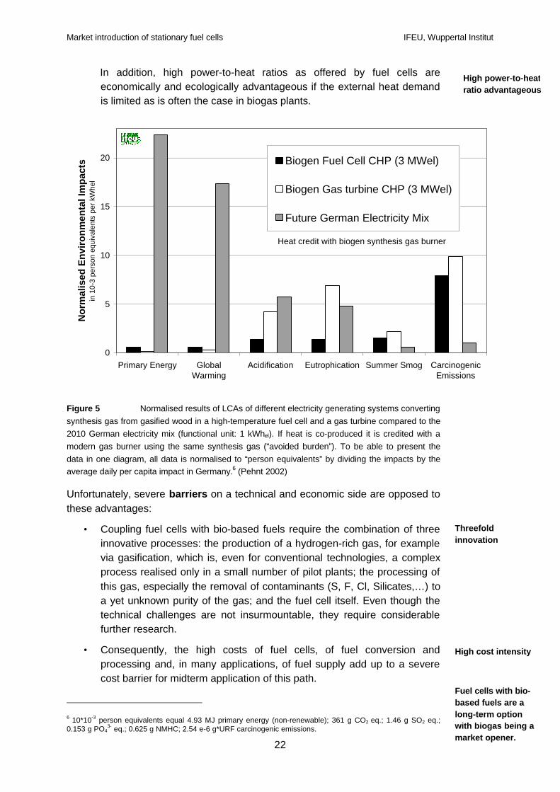
In addition, high power-to-heat ratios as offered by fuel cells areeconomically and ecologically advantageous if the external heat demandis limited as is often the case in biogas plants.
Figure 5 Normalised results of LCAs of different electricity generating systems convertingsynthesis gas from gasified wood in a high-temperature fuel cell and a gas turbine compared to the2010 German electricity mix (functional unit: 1 kWhel). If heat is co-produced it is credited with amodern gas burner using the same synthesis gas (“avoided burden”). To be able to present thedata in one diagram, all data is normalised to “person equivalents” by dividing the impacts by theaverage daily per capita impact in Germany.6 (Pehnt 2002)
Unfortunately, severe barriers on a technical and economic side are opposed tothese advantages:
• Coupling fuel cells with bio-based fuels require the combination of threeinnovative processes: the production of a hydrogen-rich gas, for examplevia gasification, which is, even for conventional technologies, a complexprocess realised only in a small number of pilot plants; the processing ofthis gas, especially the removal of contaminants (S, F, Cl, Silicates,…) toa yet unknown purity of the gas; and the fuel cell itself. Even though thetechnical challenges are not insurmountable, they require considerablefurther research.
• Consequently, the high costs of fuel cells, of fuel conversion andprocessing and, in many applications, of fuel supply add up to a severecost barrier for midterm application of this path.
6 10*10-3 person equivalents equal 4.93 MJ primary energy (non-renewable); 361 g CO2 eq.; 1.46 g SO2 eq.;0.153 g PO4
3- eq.; 0.625 g NMHC; 2.54 e-6 g*URF carcinogenic emissions.
High power-to-heatratio advantageous
Threefoldinnovation
High cost intensity
Fuel cells with bio-based fuels are along-term optionwith biogas being amarket opener.
Market introduction of stationary fuel cells IFEU, Wuppertal Institut
23
On a time-scale, therefore, this option is characterised as a long-term option for2020 and beyond, with certain niche applications (biogas from landfill, agriculturalresidues, sewage gas) being possible market openers.
4.2.2 Renewable electricity: Fuel cells in a “Hydrogen Economy”
Another possible renewable energy source for hydrogen is the production ofhydrogen with renewable electricity, such as wind power, solar thermal powerplants, hydroelectric and geothermal power etc. This significantly increases thenumber of primary energy carriers. Some of these electricity sources, such as off-shore wind parks and import of solar thermal power plant electricity arecharacterised by huge potentials. Particularly, the development of solar thermalpower plants, for instance in the Mediterranean area, offers almost unlimitedresources. (Nitsch and Trieb 2000) quantify, for instance, the potential for solarimport to Germany from North Africa to 1’360’000 TWh/a (German electricitydemand: 550 TWh/a).
However, particularly for stationary fuel cell applications, there must be goodreasons for the intermediate production of hydrogen, because the conversion ofrenewable electricity into hydrogen and back into electricity is associated withsignificant losses and additional costs. There are mainly two reasons for thedeployment of hydrogen in the stationary sector:
Hydrogen for energy transport, for example from solar thermal power plants inAfrican countries to Europe. However, for distances of that order, the transportvia high voltage direct current lines is generally cheaper (Dreier and Wagner2001; Nitsch 2002). Only for larger distances or for mobile applications, wherethe conversion to a storable fuel is needed anyway, the conversion to hydrogenseems to be appropriate. Under these conditions, stationary applications maybenefit from existing hydrogen supply.
Storage of intermittent sources, load levelling: when renewable energysources with a fluctuating generation gain importance, such as wind or solarpower, there will be rising demand for a storage or load levelling device.
- In island applications, where no supporting grid is available,hydrogen electrolysis coupled with a fuel cell will be an attractiveoption.
- In grid applications, several investigations with time-resolvedsupply and demand simulation have proven (Langniß, Nitsch et al.1997; Quaschning 1999; Nitsch and Trieb 2000) that only for highshares of renewables to total electricity supply (> 30 %) hydrogenas a storage medium might be required. This is because thefluctuating characteristics of certain renewables are to a certaindegree already averaged due to the large area distribution ofrenewables, due to the use of non-fluctuating renewables(biomass, geothermal), due to electricity import (to average out
In electricity grids,FC systems basedon renewablehydrogen will notbe required before2030.
Market introduction of stationary fuel cells IFEU, Wuppertal Institut
24
daily (east-west import) or yearly (south-north import) fluctuations),due to load management and dynamic variable power plants.
As even the ambitious solar scenarios forecast such high shares ofrenewables in electricity grids only after 2030, fuel cell systemsbased on renewably produced hydrogen will, from an energyeconomic point of view, not be required before 2030 and, in largerunit numbers, before 2050.
On the other hand, the transition from a fossil based system andits fully developed infrastructure to a “solar hydrogen system” asan ultimate goal takes a long time. Thus, research anddevelopment as well as deployment in niche markets and leadapplications already today can pave the road. It is then importantto make clear that these demonstration projects do not substitute,but supplement the development of rational use of energy andrenewable energy carriers.
4.2.3 The transition to higher shares of renewables
For the determination of a possible fuel switch to renewable energies based onfuel cells, another aspect has to be taken into account: To which degree can thistransition take place continuously, i. e. without the need for high infrastructureinvestments at discrete points in time?
In the conventional electricity sector, due to the possibility of an incrementalfeeding-in of renewable electricity, a step-by-step increase in the share ofrenewable primary energy carriers is unproblematic. For some renewable heattechnologies, higher investments are required, either in the distribution of energycarriers (e. g. wood pellets) or in the set-up of district heating systems (e. g.biomass fuelled CHP or geothermal systems). In the transport sector, there aresome opportunities for a gradual transition (e. g. E5, i.e. gasoline with 5 %bioethanol) or for fuels that only require minor modifications (e. g. bio diesel andthe set-up of bio diesel distribution/modification of vehicles). If large shares ofrenewable energy in the transport sector are desired, however, a transition tosolar hydrogen with the concomitant installation of a different fuel supply systemis necessary.
With respect to fuel cells and relevant fuels, it is possible to gradually switch fromnatural gas to renewably produced hydrogen (or biogas/synthesis gas) which canbe fed into the pipeline distribution system and ultimately replace natural gas as afuel. Biogas applications can be “greened” by feeding-in of biogas or processedsynthesis gas into the natural gas distribution system as long as minimum qualitystandards are guaranteed.7 Therefore, natural gas can bridge the gap betweenour fossil system and a more renewable based system based on hydrogen.
7 For technological approaches and difficulties of H2 pipeline transport, see (Winter and Nitsch 1989).
Gradual feed-in ofgaseous bio fuelsinto the natural gaspipeline
Market introduction of stationary fuel cells IFEU, Wuppertal Institut
25
The principal transition characteristics, thus, do not differ fundamentally fromcompeting technologies8 which could, in principal, also run with the mixture ofnatural gas and bio fuels (see, for instance, the projects of the StadtwerkeSchwäbisch Hall to run reciprocating engines with synthesis gas from wood andnatural gas (http://www.stadtwerke-hall.de)). For fuel cell systems that are notconnected to the natural gas grid, solid biomass has to be transported to the fuelcell system and gasified on-site, similarly to biomass CHP in steam turbines orreciprocating engines.
4.3 Low criteria pollutant emissions
In addition to high electrical efficiencies, the low pollutant emissions of fuel cellpower plants are a major advantage. In hydrogen operation these are zero.When reforming natural gas or methanol they are extremely low due to thecomparatively low temperatures involved and the requirement to clean upimpurities such as sulphur and CO. However, for a complete assessment ofenvironmental impacts, the entire life-cycle should be considered (see AppendixB).
Figure 6 shows that fuel cells offer great advantages with respect toenvironmental impacts that are caused by criteria pollutants, such as acidification(mainly caused by NOx and SO2), eutrophication, summer smog or carcinogenicsubstances. In these impact categories, fuel cell power plants allow reductionsranging from 40 % (Summer smog) to 88 % (Eutrophication). Unlike engine CHPplants which emit pollutants, fuel cells couple the advantages of reduced energyconsumption with low direct emissions.
For example, an investigated high-temperature fuel cell produces 70 % lessacidification on a life-cycle basis than a low-NOx gas turbine and 30 % less than amodern natural gas combined cycle plant. In the case of the fuel cell, theacidifying emissions stem almost exclusively from the energy chain and theproduction of the system. For gas turbines, in contrast, the direct NOx emissionsaccount for more than 50 % of total acidification.
8 The difference is, however, as pointed out in chapter 4.2.1, the higher harvesting efficiency of the fuel cell and,thus, the reduced requirement of (expensive and limited) renewable fuels.
Fuel cells couplethe advantages ofreduced energyconsumptioncommon to CHPwith low directemissions.
Heat credit with natural gas burner.CHP: Combined Heat and Power ProductionCC: Combined Cycle
SO
FC
CH
P (
3 M
W)
Gas
turb
ine
CH
P (3
MW
)
PE
FC
CH
P (
200
kW)
Eng
ine
CH
P (2
00 k
W)
SO
FC
(no
CH
P) (
20 M
W)
Nat
ural
Gas
CC
(600
MW
)
Fut
ure
Ger
man
Ele
ctric
ity M
ix
Fuel
Cel
ls
Co
nve
nti
on
al
Figure 6 Normalised results of LCAs of different electricity generating systems (non-renewable fuels) for various impact categories (functional unit: 1 kWhel). If heat is co-produced it iscredited with a modern natural gas burner (“avoided burden”). All data is normalized to personequivalents by dividing the impacts by the average daily per capita impact in Germany (see Figure5). Data taken from (Pehnt 2002).
The relevance of pollutant emission reduction not only depends on theenvironmental significance of the pollutants, but also on the specific contributionof electricity production/energy conversion to total European emissions. Forinstance, only 19 % of European NOx emissions stem from the sector „energyindustries“ with the dominant part emitted by transport (http://themes.eea.eu.int).
For SO2, “energy industries” contribute nearly two thirds of total emissions. Here,however, a significant reduction has already taken place (1998 30 % of 1980emissions, with further achievements in the past 5 years). Thus, the absoluteemission levels are much lower than some time ago.
Beyond EU 15, however, the emission situation is different. In central andEastern European countries, for instance, pollutant emission levels are muchhigher. Here, fuel cells would bring down emission levels instantaneously.However, in these countries, capital cost is an even more critical issue than inEU 15 countries.
4.4 Noise, vibration, space
Since fuel cells contain only few rotating parts, noise emissions and vibration arelow. The phosphoric acid units, for instance, have noise rates of 66 dB(A) at 10 mdistance. Also, the 11 MW units that run on higher pressure and have largercompressors are rated at <65 dB(A) at 30 ft from the site fence.
The noise is produced especially by the balance-of-plant components,particularly the compressor. It can be attenuated with appropriate noise
Market introduction of stationary fuel cells IFEU, Wuppertal Institut
27
protection devices. In the case of a hospital installation of the mtu hot-module, forinstance, the compressors were protected with noise insulation.
In domestic applications, where conventional small reciprocating engines are toonoisy for individual buildings; fuel cells could offer significant advantages.
Sometimes, the compactness of fuel cells is mentioned as an advantage. Due tothe pilot plant character of the systems realised today, it is difficult to derive thefuture space requirements. For Phosphoric Acid Fuel Cells, for instance, therequired volume of the PC-25C could be halved compared to the PC-25A. Today,the PC-25C requires 83 m2/MWel, comparable to the Alstom Ballard system (79m2/MWel). Other pilot plants which were not optimised with respect to space, arein the range between 290 (100 kWel SOFC Westervoort) and 450 (11 MWel
system in Japan) m2/MWel. The Hot Module will require 90 m2/MWel, the SiemensWestinghouse system approx. 170 m2/MWel. Further improvements can beachieved by higher power densities and better system integration.
For comparison, a typical 3 MWel gas turbine system requires 15 m²/MWel, anatural gas combined cycle plant 65 (200 MWel) to 30 (600 MWel) m2/MWel
(IKARUS 1994; DLR, Dienhart et al. 1999), and a reciprocating engine between 8and 34 m²/MWel for 3 to 0.28 MWel systems, including heat integration.
The compactness of a system might be a special issue in the case of domesticsystems; today’s systems, with weights at around 450 kg for 1 kWel (SulzerHEXIS), are extremely difficult to install by local craftsmen. Therefore,considerable development in this area is required. Further, in many countrieshouses have no basement. Thus, wall mounting the systems is required.
4.5 Heat levels suitable for industrial and cooling applications
Due to the high operating temperatures of MCFC and SOFC they are suited fordifferent kinds of CHP applications, from house and district heating applications(90-120 °C) to cooling applications to industrial process heat supply up to 400 °C.Of the conventional CHP technologies, the gas turbine has a similar flexibility,whereas reciprocating engines typically produce heat up to 90 °C (only in specialapplications flue gas and cooling water heat are used separately with thepossibility of higher temperatures).
If one analyses the amount of industrial heat demand as a function oftemperature (Figure 7), only 35 % of the total demand lies below 500 °C and istherefore suitable for CHP. In the temperature range between 500 °C and 800°Cthe heat demand is rather low. Only above 800 °C, a considerable amount ofheat is consumed primarily for anorganic processes. These are no suitableapplications for CHP. Therefore, the – compared to the gas turbine potentiallyhigher – temperature of the SOFC flue gas does not result in considerablyincreased industrial applications. Rather, gas turbine and high-temperature fuelcells can, in terms of temperature, equally well serve the industrial process heat.
High-temperatureFC offer similarfeatures withrespect toindustrialapplications as gasturbines.
Mass and volumemight beparticularly criticalfor domestic CHP.
Market introduction of stationary fuel cells IFEU, Wuppertal Institut
Figure 7 Fuel consumption as a function of process temperature according to (Hofer1995), cited after (DLR, Dienhart et al. 1999)
As another interesting application, the demand for cold (air-conditioning,refrigeration, and freezing) has increased in the past years, with further growthexpected in the coming years. The use of absorption chillers is also attractivebecause absorption chillers work with heat as energy source whereasconventional compression chillers need electricity. For providing the heat toabsorption chillers, high-temperature fuel cells are more appropriate thanreciprocating engines. This is due to the fact that for cooling energy at 6 °C via anabsorption chiller, a temperature of the heat source between 60 and 90 °C issufficient, but for temperatures below 0 °C, an absorption cooling device requires120 to 180 °C (DLR, Dienhart et al. 1999). These higher temperatures wouldrequire to use the heat from the exhaust gas heat exchanger only (not from thecooling water circulation) which cannot provide such high flow rates.
4.6 Dynamic load response
In certain applications, for instance for grid conducted operation of fuel cells,where the load is determined by the load of the grid and a dynamic response isdesired to supply regulating energy, the dynamic response particularly of low-temperature fuel cells will be of advantage. Thus, the electricity supplied canpotentially be of higher economic value when together with suitablecommunication devices, a second-by-second response is possible. However, thedynamic response is much less pronounced for high-temperature fuel cells andyet has to be demonstrated. Here, thermal cycles and the heat capacity of thesystem may limit the response rate and the minimum allowable partial load.
Low-temperature fuel cells have the potential for high dynamics and may reachsimilar dynamics micro-turbines exhibit today.
For coolingapplications,particularly below6 °C, HT-FC aremore appropriatethan reciprocatingengines.
Market introduction of stationary fuel cells IFEU, Wuppertal Institut
29
4.7 High power to heat ratio
For certain applications it is desirable to have CHP systems with a high power toheat ratio (i. e. the ratio of the electrical and the thermal efficiency). Here, fuelcells offer power-to-heat ratios > 1 (except for domestic systems) which might beadvantageous.
In some applications, for instance, the co-product heat cannot be used but mustbe cooled away, thus reducing the total efficiency considerably. One example arecertain biogas plants, where the heat is used for the anaerobic process and forheating the premises, but often considerable amounts of excess heat cannot beused due to the large distance to settlements (Pehnt 2002). Here, fuel cellspromise a better use of biomass resources.
In some industrial applications requiring high amounts of electricity, high power-to-heat ratios are economically advantageous. For instance, this is the case inmetal processing/ electroplating companies and electrolytic production ofaluminium, chromium or magnesium (DLR, Dienhart et al. 1999).
4.8 Synergies to mobile sector
As there is still substantial R&D effort required to bring down fuel cell capitalcosts to allowable levels (see chapter 5.1), every approach to reduce cost iswelcome. One possibility is to exploit synergies between mobile and stationaryapplications which could occur on several levels:
§ joint purchasing: companies could get better purchasing conditions whenbuying materials or components in larger amounts;
§ joint R&D, for instance developing membrane electrode assemblies withreduced catalyst loadings for both applications;
§ joint use of identical components and processing steps, thus allowinghigher unit numbers and lower costs (example: marketing a vehicle stackalso for premium power applications); particularly important in the initialphase where for vehicle applications, systems are still too expensive, andwhere stationary applications could offer an early market;
§ joint build-up of a H2 infrastructure; in a long-term perspective, stationaryfuel cell systems with integrated reformers could supply hydrogen to thefirst pilot vehicles thus eliminating the need for an extra H2 filling station(see Plug Power & Honda);
§ and, in the very long-term, the vehicle to grid (V2G) approach, where fuelcell vehicles are connected to the electricity (and potentially heatdistribution) grid to supply, for instance, peak load, spinning reserves orregulating energy (Kempton, Tomic et al. 2001).
When assessing these synergies, one has to keep in mind that in stationary andmobile applications, totally different specifications have to be fulfilled. In vehicles,a stack life-time of 4000 h may be sufficient, whereas in stationary applications,
Market introduction of stationary fuel cells IFEU, Wuppertal Institut
30
the life-time typically has to be an order of magnitude higher. This reduces thejoint R&D possibilities and the feasibility of the V2G approach. On the other side,the major part of the R&D efforts of the companies (from which also stationarysystems will benefit) is motivated by the strict cost targets of mobile applications.
Thus, some car manufacturers, such as Toshiba IFC, announced to start massproduction of 5 kWel PEM fuel cells for residential applications (press release3/2/2003).
For others, the stationary application offers an early market. General Motors forinstance develops a 70 kW stationary system based on the vehicle stack forpremium power use. In the premium power sector, lower life-times andefficiencies and higher capital costs are not so relevant and reliability is the keyissue.
These intermediate products help the mobile applications because the high R&Dcosts can be lessened to a certain degree. However, stationary fuel cells,particularly larger systems (> 200 kWel), will not to the same extent profit fromthese synergies because for them, less overlapping applications exist, whereasfor small scale domestic systems one could imagine such cheap capital costsdue to developments in the mobile sector that replacing a stack would be nobarrier for the economics of that system.
Additionally, such synergies between the mobile and the stationary sector are notspecific to the fuel cell business segment. For instance, General Motors alsodevelops a micro-turbine jointly for stationary and vehicle applications in a serieselectric hybrid. Another example for such synergies are reciprocating enginesused in CHP which are mainly based on vehicle combustion engines and can,therefore, profit from developments made for the vehicle market. Nevertheless,despite these synergies, these technologies have to fight for their economicsurvival.
4.9 New business segments for IPP, small scale CHP, gas suppliers andenergy services
4.9.1 Premium power
Many businesses — especially the growing number dependent onmicroprocessors — need high-quality, reliable electricity to keep manufacturingprocesses going, or to provide services such as financial transactions. Powerquality therefore is an important concern for today’s power grid and the loads thatit serves.
Traditionally, electric utilities have assured reliable service to what is called “fournines”, that is, power will be available 99.99% of the time. But high-techindustries like internet server farms and computerized banking systems demand
Market introduction of stationary fuel cells IFEU, Wuppertal Institut
31
much higher reliability, in the range of “nine nines” (available 99.9999999% of thetime) (Mansoor, Keebler et al. 2000).
Creating this level of reliability can potentially be achieved using traditional gridtechnologies — for example, by supplying multiple power feeders to the systemand providing a backup line from a hydropower station — but the cost is high,and the reliability is generally guaranteed at the expense of service to othercustomers. Yet a typical computer system annually experiences around 300power disturbances outside the manufacturer’s voltage tolerance limits.
However, even momentary power disturbances can cost some businessesmillions of dollars (Table 3). According to DOE's Office of Distributed EnergyResources, power fluctuations and outages cost U.S. business about $50 billiona year (DER 2003).
Premium power userTypical cost for
1-hour interruption
Cellular communication $41,000
Telephone ticket sales $72,000
Air reservation system $90,000
Semiconductor manufacturer $2,000,000
Credit card operation $2,580,000
Brokerage firm $6,480,000
Table 3 Examples for hourly costs of power outage in the US (Source:http://www.gm.com/automotive/innovations/Fuelcell/fuel_cell_cost.html)
Depending on the specific technologies, site conditions, and potential interactionwith the existing electric power system, various distributed energy resources(DER) including fuel cells represent a way to address the emerging need for highpower quality. Some energy consumers have already responded by installingtheir own distributed energy systems. The First National Bank of Omaha, forexample, uses fuel cells to run its credit card processing centres, thereby savingup to $6 million per hour of power outages (DPP 2003). More elaboratedconcepts are power parks (also called “premium power parks”) that include on-site power sources to increase reliability in combination with uninterruptiblepower supplies, such as battery banks, ultracapacitors, or flywheels.
Due to the few moving parts and the reliable mechanisms underlying the fuel cell,it is often regarded as a highly reliable systems. The operating experience gainedso far underlines that as long as “teething troubles” of new technologies will beovercome this could turn out to be a valuable advantage of fuel cells. Forexample, PAFC have demonstrated 98+% uptime when run on clean fuels andsuitable care. When operated with premium service, between 96.8 and 99.4 %were achieved (Lovins, Lehmann et al. 2002). Based on PAFC technology,99.9999 % reliable systems are offered by some companies (e. g. SurePower).However, so far, with the exception of some PAFC systems, “the long-term
Fuel cells are oneoption for powerquality solutions
Market introduction of stationary fuel cells IFEU, Wuppertal Institut
32
performance and reliability of certain fuel cell systems has not been significantlydemonstrated to the market” (NFCRC 2003).
4.9.2 Domestic CHP as new market opportunity
In addition to the market segments mentioned above, fuel cells, possibly incombination with Stirling engines, might open up a completely new marketsegment: that of domestic CHP (MicroCHP). The mass market for MicroCHP willbe for the replacement of gas heating boilers (Harrison and Redford 2001).Because of the vivid development of small fuel cell heating systems, thedevelopment of domestic systems is well on the way. Experience with firstactivities of some energy suppliers (e. g. EWE and EnBW in Germany) where thecompanies were overrun by people interested in such systems show that fuelcells enjoy a high confidence of end-users who would have no objection to installthese systems in their houses (Ballhausen 2002).
The domestic sector micro cogeneration could, if the right market and economicfactors support this segment, represent a considerable market. The FutureCogenproject estimated that under optimistic assumptions, by 2020 up to 50 GWel inEU15 could be installed in this sector (Future_Cogen 2001). Micromap calculatesdifferent scenarios, with up to 12 million MicroCHP systems delivered in Europeby 2020 in the optimistic and 5 million in the Business as Usual scenario(MicroMap 2002). United Kingdom, Germany and Netherlands are seen as initialmarkets for MicroCHP. In addition, some 700.000 units could be installed inCentral and Eastern European countries.
One of the key factors for economic viability is the electricity price (see chapter5.1) which enters the calculation because either domestic electricity consumptionis displaced – and thus associated costs eliminated – or because electricity is fedinto the electricity grid with a corresponding feed-in tariff. Due to the high capitalcosts of any MicroCHP system, related connection issues, and the morecomplicated installation process, these systems are likely to be marketed byEnergy Service Companies (ESCos).
In this market for MicroCHP, Stirling engines will be close competitors. Inspite ofa lower electrical efficiency, Stirling engines offer high total efficiencies as well asflexibility with respect to fuel contamination because they rely on externalcombustion.
4.9.3 New energy services for the household customers
It is commonly expected that the market introduction of fuel cells in the householdsector will depend on a supply push. The manufacturers and other involvedparties have to take a pro-active role in order to increase the attractiveness of thenew solution. For this reason, the key to the market success of fuel cell heatingsystems is commonly seen in “one-stop solutions”, providing a complete servicepackage to the customer (Figure 8). It is foreseen that manufacturers, licensed
Stirling enginesmain competitors
Fuel cells mightopen thecompletely newmarket of domesticCHP
Energy servicepackages seen askey to marketsuccess
Market introduction of stationary fuel cells IFEU, Wuppertal Institut
33
installation contractors and/or utilities will take care of installation, operation andmaintenance of the device and will coordinate the integration of the CHP into thepublic grid. Obviously, the widespread dissemination of such energy services willrepresent the precondition for realizing the concept of a virtual powerplant//virtual utility.
In line with this emerging market for new energy services (micro-contracting) fuelcells offer new business opportunities, e. g. for utilities that aim at providing abroad range of supply services (multi-utility approach).
The starting conditions for such service offers are quite favourable since heatrelated energy services have already been introduced to the market so thatnecessary competence and experience is available. Compared with otherapproaches of third-party financing and performance contracting schemes, heatservices which demonstrate the highest growth rates and most favourable marketprospects might push the introduction of fuel cells.
In the commercial and industrial sector a comparable chance can be seen forenergy service companies (ESCOs), which evaluate energy use, recommendenergy management strategies, and provide related services, including a varietyof supply-side and demand-side options — see new opportunities for selling,financing, and managing distributed generation and load reduction technologiesand approaches.
planningfinance
marketing
supply of equipmentinstallation
operationmaintenance repairsbilling
replace-ment,
updatecustomer requirement:space heating, warm waterelectricity, air conditioning
energy managementremote control
consulting
Figure 8 Energy services bundled to “one-stop-solutions”
4.9.4 Market opportunities for gas utilities
The gas utility sector envisages ambivalent mid-long-term market prospects.Whereas in many sectors such as power generation, gas demand is rising, inother segments such as new urban settlements, space heat demand – andcorrespondingly gas demand – is decreasing. Energy saving standards and
Domestic gasdemand decreases– fuel cells offernew market sharesfor gas utilities
Market introduction of stationary fuel cells IFEU, Wuppertal Institut
34
innovative constructions allow to squeeze the specific energy consumption below50 kWh/m2*a and even much less. Among gas utilities this is often considered tobe the critical threshold to profitably operate a gas grid. As a result in certainregions, such as in development areas in rural regions, gas supply companiesdecide not to invest in a gas distribution system.
In a longer perspective (see chapter 6), significant shares of the domestic heatmarket risk to get lost for the gas industry so that natural gas based CHP via fuelcells offer a new option to promote gas use. In addition to innovative gasappliances such as gas fired tumble dryers, etc. gas demand is increasedsignificantly by fuel cells due to the simultaneous production of heat andelectricity.
4.9.5 New options for supply of backup power
Fuel cell CHP systems that follow the heat demand of end-users will generate arather stochastic electricity production. However, fuel cells can be used as well asa means to manage the end-users’ electric load curve, especially when severalunits are interlinked through information technologies and centrally controlled.Appropriate timing of operation can contribute to peak load shaving,compensation of seasonal load asymmetries and provide the option to balancethe increasing share of intermittent generation from renewable energy sources.
Grid-related operation strategies of fuel cells, therefore, are of special interest forsystems operators and distribution utilities. They are obliged to purchaseexpensive back-up power from reserve capacity in order to balance thedifferences between load prognosis and factual demand. In this context, the loadmanagement of fuel cells creates specific added value that adds to theprofitability of installations. New opportunities emerge with regard to
• a fixed electricity generation according to pre-negotiated load profiles, i. e. anexclusion of stochastic feed-in;
• provision of back-up power from spinning or supplemental reserves that canbe used to balance excess demand and peak loads;
• regular selling of electricity in liberalised energy markets on the basis offlexibly negotiated supply contracts , e.g. on the energy spot market.
In order to benefit from these options, however, remarkable progress in gridrelated RTD is required. In addition to the ongoing technology development ofstationary fuel cells, an additional line of innovation has to be opened up (Figure9). Technical solutions for grid interconnection, communication and control aswell as the necessary regulatory and institutional arrangements have to beachieved. It can be expected that grid related solutions and products will enterthe market with a certain delay compared to the single stationary fuel cellapplication. Due to the fact that not only fuel cells, but other kinds of conversiontechnologies such as reciprocating engines are suited for the purpose of backupsupply, these available options can already be used to develop the field (see for
New value addedthrough grid-related operation offuel cells
Market introduction of stationary fuel cells IFEU, Wuppertal Institut
35
instance the Stadtwerke Unna project that aims at creating a network of remotecontrolled reciprocating engines and micro-turbines (www.sw-unna.de)).
concepts fornew applications- grid orientated operation- virtual power plant (VPP)
developmentvirtual power plant
pilot-/demo projects- ICT interconnection- energy management- load management- integration into remote control
interactivegrid compatible"intelligent"CHP systems
- grid impacts- power quality- balance & settlements
local VPP
- peak power shaving- intra-day-trading
large-scale VPP
- provision of large-scale back-up power
grid related services- trading
- grid operation- grid management
CHP-system fordistributed generation
- standardised- competitive
DSO, trader TSO
value addedbusiness segments
installationsinfrastructures
optimisation
VPP - virtual power plantCHP - combined heat & power generationDSO/TSO - distribution/transport system operator
time2000
Figure 9 A new technology field is required to generate innovative business opportunitiesfor fuel cell operators in the field of grid support services
Moreover, it has to be kept in mind that due to the relatively small size ofdomestic fuel cells an aggregation of units appears to be inevitable.Commercially attractive capacities will hardly be realised without a pooling andcentral control of a larger number of applications. A widespread deployment offully integrated distributed power generation from fuel cells and othertechnologies enables advanced operating concepts such as the self-healing grid,micro-grids and the virtual utility (CEIDS 2002). These concepts hold thepotential for providing the high reliability, quality, security and availability ofelectrical service required by society.
Triggered by recent advances in IT-technology, virtuality is a new concept forenergy industry in which transactions between buyers and sellers of electricitywould be handled in a non-traditional manner9. For example, an operator of a
9 Apart from new arrangements on the supply side, new modes of bundling of demand such as bulk purchasethrough a virtual consumer/buyer can be possible.
Market introduction of stationary fuel cells IFEU, Wuppertal Institut
36
virtual power plant could own several distributed energy resource (DER) unitssuch as stationary fuel cells and remotely dispatch energy and capacity inaccordance with contractual agreements made with the buyers of its services.This operator would act as a virtual utility as long he is able to remotely monitorand control the fuel cell units and the consumer’s energy management system aswell as to respond to external signals, e.g. price signals from buyers in the spotmarket. In a more general case, the virtual operator may also own other types ofequipment that enable it to provide other types of services like improved powerquality or load management. Most or all functions necessary for the operation ofthe virtual utility, such as maintenance, billing, and information technologysystem, could be outsourced. In fact, the distributed generation units and otherequipment used to provide services could be owned by other entities andmanaged by the virtual operator. Collectively, the changes will mandate theoverall physical infrastructure of the distribution system to evolve into somethingthat is capable of supporting the business arrangements of the virtual utility.Figure 10 shows a schematic of the virtual utility.
CHP
PV
wind power
virtual utility(virtual power plant)
loads
local utility central powergeneration
(intermittent)renewableenergies
distributedgeneration
Micro-CHP
CHP
biomassCHP
ISO
price signalssystemrequirements
control signals
controlsignals
feed-ininformation
Figure 10 Schematic of the virtual utility
4.10 Possibility of ‚simpler’ CO2 storage
When a complete fuel switch to renewable fuels is not possible under certainconditions, one alternative is to reduce the impacts of the fossil fuel conversion.Of particular interest in this context is coal that has large reserves especially insome countries with high increases in electricity demand (e. g. China). It hasbeen discussed for some time that the capture and subsequent storage of the
Market introduction of stationary fuel cells IFEU, Wuppertal Institut
37
CO2 which is produced when the coal is combusted would offer a new option toproduce electricity with climate-compatible coal plants (see, for instance, (IPCC2002)). Beside the necessity to dispose of the CO2, e. g. by storage in oil fields,caverns or aquifers, carbonation via magnesium hydride, etc., it is also necessaryto capture the CO2. There are two basic options: capture from the atmosphere, ordirect absorption of the CO2 in the power plants. For the latter, a number ofinvestigations have been carried out with the goal to optimise the powerconversion processes (high CO2 content in the flue gas) such that minimumefforts have to be taken to remove the CO2. One option was to develop IGCCpower plants which include a coal gasification and allow the capture of the CO2 inthe synthesis gas prior to combustion.
In the debate on CO2 storage, the fuel cell enters the stage primarily due to tworeasons:
In the mobile sector, the many decentralised CO2 emission sources in thevehicles make a CO2 capture very difficult. The centralised hydrogen (H2)production for hydrogen vehicles would allow an easier capture of the CO2 at theH2 plant. This enables to tap the CO2 reduction potential of the mobile sector.
In the stationary sector, fuel cells might, due to the separate flows of anode andcathode, in principal offer good conditions for a rather high CO2 concentration inthe flue gas. In the recent DoE FutureGen initiative, for instance, production of ahydrogen rich synthesis gas from coal with subsequent CO2 capture andelectricity production in a fuel cell is planned (DoE 2003). Siemens Westinghousecarried out a study to find out specific technological set-ups (using a part of thefuel cell stack as an “oxygen pump” to avoid diluting the flue gas) to have onlyCO2 (and H2O which can easily be removed) in the flue gas (Hassmann 1999).The study concluded that this set-up is principally possible, with many materialsscience issues to be addressed. One particular application of that design is theuse on oil platforms where the CO2 can be pumped into the reservoir, thusenhancing the oil yield of the deposit (enhanced oil recovery).
Even though, from a technical point of view, the combination of coal gasification,fuel cells and CO2 storage seems attractive, a number of severe short-comingsprohibit the realisation of such plants as a near or midterm option:
- Technical feasibility. For each of the process steps, i. e. coal gasification,decarbonisation of the flue gas, fuel cell, and CO2 storage, severe technicalproblems have to be solved. This is particularly true for the storage (forinstance storage quality, impacts of an increased pressure in geologicalformations, etc.), but also for, for instance, fuel cells, where additionaltechnical adaptations to the CO2 capture process are required.
- Low efficiencies. A recent study (Köhler, Krammer et al. 2003) could notconfirm the high efficiencies of the fuel cell/carbon capture system from thelarge Zero Emission Coal project, but rather forecasted an electrical efficiency(LHV) below 40 % (without considering CO2 storage). This is less than inIGCC projects. The efforts for CO2 transport and storage further reduce thisefficiency.
In mobileapplications,hydrogen offers thepossibility tocentrally capturethe CO2.
In stationaryapplications, Fuelcells might, in thevery long-term,allow a bettercapture of CO2
from the flue gas.Due to high capitalcost, low electricalefficiencies andprevailing technicalproblems, andopen questionsregarding safetyand CO2 leakage,the use of coal gasin fuel cells withsubsequent CO2
storage is not seenas a successfulclimate strategy forthe next 50 years.
Market introduction of stationary fuel cells IFEU, Wuppertal Institut
38
- Cost. Furthermore, the costs of carbon capture and storage (see for instance(Enquete 2002)) in general and particularly of fuel cell/carbon capturesystems (Köhler, Krammer et al. 2003) are significantly higher thancompetitive processes even if the target costs for fuel cells are used for thecalculation. Additionally, the use of renewable energy carriers sets abenchmark for CO2 reduction costs. (Köhler, Krammer et al. 2003) thereforedraws the conclusion that „due to technical barriers, lacking feasibility andhigh capital costs the realisation of this process is not foreseeable.“
- Risk and environmental aspects. Some severe environmental and safetyaspects concerning CO2 capture and storage remain unresolved and needsignificant further consideration. Depending on the various capture andstorage options, these include, for instance, continuous leakage rates(depending upon the cap rock integrity and the security of the well cappingmethods), the risk of sudden CO2 releases, waste, groundwater issues,ecosystem compatibility, etc. (see for instance (Enquete 2002; Johnston andSantillo 2002)).
Our conclusion is that coal fuel cell plants combined with CO2 storage will notcontribute significantly to GHG abatement in the next 50 years.
4.11 Opportunity to de-block current ignorance vis-à-vis CHP
As we have seen, fuel cell heating systems offer a wide range of interestingimplementation cases and some exciting prospects for the future. In any case,they represent an innovation to the traditional market for heating systems.Moreover, due to the innovative character they represent an opportunity to de-block the still prevailing ignorance vis-à-vis CHP solutions.
As opposed to areas like consumer electronics, average end-users are barelyinterested in the technical aspects of their heating system and only littleknowledge about efficiency, emissions, etc. can be found. Today, the heatingsystem is a black box without any further appeal; it is hidden in the cellar.Accordingly, the specific value added and the environmental benefits of CHPsolutions – especially from a system’s perspective – will hardly motivatecustomers to make extra efforts or to take technical risks during the marketintroduction phase. Even CHP solutions that are widely available and marketproven still suffer from marketing problems although they demonstrate technicalreliability, convincing performance and a competitive price.
In this situation, all solutions on the CHP market can benefit from the currenthigh-tech image of fuel cells as a clean technology. Fuel cells might become as“sexy” as PV panels and can open the eye for the hidden potential of combinedgeneration. This effect should be deliberately exploited for social marketing notonly of fuel cells but of the important role of CHP in general.
However, one could also reverse the argument: once the fuel cell euphoriadiminishes, the ignorance regarding the heating system or the electricity supplymight dominate the consumer’s perspective; consequently, only the economic
"Sexy" image of FCopens the eye forCHP benefits
Market introduction of stationary fuel cells IFEU, Wuppertal Institut
39
attractiveness of the systems would prevail the purchase decision. Onlyextensive marketing and educational efforts could then consolidate the image offuel cells.
4.12 Further advantages common to all distributed generationtechnologies
There are further advantages of fuel cell systems that are common to alldistributed generation technologies. These will only be mentioned briefly here.
4.12.1 Reduced transmission/distribution losses and less required grid
capacity
Depending on the load of a grid, its capacity, the weather conditions etc., aconsiderable amount of energy might be lost because of transmission anddistribution of electricity. Whereas in many countries, these losses are in therange of 5 to 8 %, under certain conditions (high load, low voltage, weak grid,etc.) they might be as high as 15 %. Even in Europe, estimated average lossesvary between 3.7 % (Finland) and 9.9 % (Ireland) (Ofgem 2003). DGtechnologies, and fuel cells as well, are considered to reduce these losses due tofeed in of electricity, thus reducing the currents in the cables (for furtherinformation on this issue, consult (Dunn 2000; Lovins, Lehmann et al. 2002)).
4.12.2 Reduced vulnerability of the energy system
A reliable and safe supply of electricity is the indispensable foundation of westerneconomies and the emerging digital society. For instance, EPRI estimatesindicate that the proportion of U.S. electricity requiring highly reliable, digitalquality power will grow from 0.6% of current consumption to nearly 10% by 2020,and that the proportion of enhanced reliability will grow from about 8-10% tonearly 60% (CEIDS 2002) (see also chapter 4.9.1). In this context thedevelopment of a robust and “self-healing” transmission and distribution system –capable of automatically anticipating and responding to disturbances, whilecontinually optimising its own performance – will be critical for meeting the futureelectricity needs of industry and the knowledge society.
In combination with new information and communication technologies,sophisticated sensors, and operation and management practices, distributedpower generation by fuel cells can make a contribution to the avoidance ofwidespread network failure due to cascading and interactive effects – threatsinclude intentional disturbances by terrorists, natural disasters, and materialfailures. Decentralised power generation will thus complement efforts to increasegrid security in response to the threat of terrorism.
Market introduction of stationary fuel cells IFEU, Wuppertal Institut
40
4.12.3 Modularity of the system
CHP systems in general, and particularly fuel cells, can be installed in a modularway. Thus, instead of installing large-scale power plants with a sudden highincrease in installed capacity, a step-wise build-up of capacity can be realised.Under certain circumstances, this may be of economic advantage (caused bereduced forecasting risks, reduced financial risks and reduced risk oftechnological or regulatory obsolescence, see (Lovins, Lehmann et al. 2002)).Another advantage of this modularity is the possibility to pre-install the fuel cellsystem in containers, thus lowering the time to install the system. In addition, forexample in the case of stack manufacturing, economies of mass can be realiseddue to higher possible unit numbers. On the other hand, certain components, forinstance the reformer, show increasing specific costs with decreasing size(economy of scale) that offsets this trend.
Economic benefitsthrough modularinvestments
Market introduction of stationary fuel cells IFEU, Wuppertal Institut
41
5 Barriers, challenges and open questions
In analogy to the discussion of the advantages and drivers for fuel cells above, inthe following sections, main barriers and open questions regarding stationary fuelcells (Figure 11) will be outlined and investigated.
• Time gap between Kyoto CO2 reduction andreadiness for marketing
• Danger of over-heated euphoria, little tolerance toinitial start-up problems
Further barriers common to all CHP systems, suchas:
• interconnection issues and grid access• heat distribution• ...
• Lifetime of stack, degradation• Reliability and compatibility of balance of plantcomponents
• Achieving target electric efficiencies• Thermal efficiencies• Availability of Balance-of-Plant components• Technical aspects of grid connection
• Investors waiting • Complexity of technology and interactions with electricity system demands one-stop solutions
• Customer acceptance of new technologies anddistribution channels (e. g. contracting)
• Installation personell: cooperation of craftsmen ofdifferent trades, etc.
• Qualification and training demand• Transaction costs for systems integration (e.g. as virtualpower plant)
• Insufficient integral planning of energy supply/demand ofobjects, buildings, settlements, communities,...
• Capital cost, distance to allowable costs• Future demand, such as reduced heatdemand
• Structural changes in traditional heat markets• International codes, standards and safety regulation• Strong competition of other technologies and fuels• Unfavourable conditions for competition with establishedgeneration (no level playing field, aggressive price dumping,etc...)
• Institutional/regulatory barriers to market access, e.g. in termsof backup power
Energy Economic, Legal Customer, Installation and Marketing
Technical Miscellanous
Barriers, challenges and open questions regarding
stationary fuel cells
Figure 11 Potential barriers and open questions regarding fuel cells in stationaryapplications
5.1 Cost
The main challenge for fuel cells is to achieve the competitive cost goals. Instationary applications, cost targets are not quite as strict as in mobileapplications where system costs in the order of 50 to 100 €/kW have to be met.However, the two applications cannot directly be compared to each other.Stationary applications have to fulfil higher standards because in typicalapplications, tenfold higher stack lifetimes are demanded, and the high electricefficiencies of the competing technologies will require operating the systems atmuch lower current densities than in mobile applications (where the efficiency is
Market introduction of stationary fuel cells IFEU, Wuppertal Institut
42
considerably higher) thus leading to an enhanced requirement of active fuel cellarea (= cost).
5.1.1 Cost targets
The target costs of fuel cells, i. e. the allowable costs at which fuel cells willbecome competitive, are determined by the market segment, by the costs of thecompeting technologies and by the energy economic developments, e.g. in termsof energy taxation. Due to the higher efficiency of the fuel cell system, fuel costsare lower and the maintenance costs are typically assumed to be lower than, forexample, in gas turbine applications. This leads to higher allowable capital costsfor the fuel cell system. In several studies, the allowable capital costs per kWel
are specified to be around 20 to 30 % above the competing technologies (see, forinstance, (DLR, Dienhart et al. 1999)). This represents a comparatively lowincrement which partially results from the required replacement of the stack.
Typically, in smaller systems the allowable cost difference increases because ofthe higher efficiency advantage of fuel cell systems. Furthermore, in domesticapplications, the high household electricity costs increase the economiccompetitiveness of fuel cells so that in this application, the allowable costs of canamount to up to 2’000 €/kW (Table 4).
Factors strongly influencing the allowable costs are:
• the future electricity costs (when the costs are compared to the separateproduction of electricity and heat) and the feed-in tariffs for self-producedelectricity from CHP
• the ratio of electricity replacing own demand compared to the electricityfed into the grid; due to different economics – replaced own demand isusually more attractive (unless there is no significant financial support bythe government) than feed-in because the compensation by the netoperator is lower than the cost of electricity supply – this can lead tosubstantially different economic situations
• the cost of natural gas
• the cost of the conventional heat production to which the fuel cell systemis compared to
• the operational mode (heat conducted, electricity conducted, gridorientated, or combinations)
• the lifetime of the system (costs for stack replacement)
• the load factor of the system
• via the parameters mentioned above, certain demand patterns of theobjects, such as ratio of electricity to heat demand, baseload demand,etc. determine the allowable costs.
Market introduction of stationary fuel cells IFEU, Wuppertal Institut
43
Table 4 Allowable capital cost ((DLR, Ifeu et al. 2003), (DLR, Dienhart et al. 1999)(industrial CHP))
Market segment Allowable capital cost (€/kWel) compared to
separate
production*
reciprocating
engine/gas turbine
Domestic (2kWel) 2000
10 “passive houses” (2kWel) 2500-4000
small multifamily residence 2200 2000
small district heating 800-1800 ** n. a.
Industrial CHP n. a. 1070
* (condensing boiler and electricity mix) ** depending on the share of own consumption/grid feed-in
To bring down investment costs of fuel cell systems, various measures have tobe taken:
§ Improving fuel cell stack design (increased power densities, particularlyfor high-temperature fuel cell systems; altered structures such as thinelectrolytes, anode-supported systems, adopted SOFC tubes, etc.);
§ Reducing degradation and increasing tolerance towards gascontaminants, thus reducing gas cleanup efforts;
§ Using lower cost materials (e. g. conventional steel for the mtu hot modulevessel, cheaper separator plates, etc.);
§ Minimizing temperature constraints (e. g. lowering SOFC operatingtemperature to use lower cost materials and sealings, or enhancing PEFCtemperature to reduce gas cleanup requirements);
§ Using reliable and standardised fuel processing and other balance-of-plant components (power electronics, etc.);
§ Learning effects due to higher unit numbers. For that purpose, high-volume production in the order of hundreds of Megawatts are required;
§ Streamlining manufacturing processes.
It has to be underlined that there is a certain trade-off between cost reduction andhigh performance so that achieving cost and performance goals simultaneouslyseems to be the major challenge for research and development.
To try a first quantification of possible learning effects, one can use the conceptof learning curves which show the dependence of unit costs on the cumulativeproduction. From a range of products, learning factors were derived whichdescribe the percentage the cost is reduced to when the cumulative production ofa product is doubled. For many products, learning factors between 0.7 (very high
Market introduction of stationary fuel cells IFEU, Wuppertal Institut
44
learning effects) to 0.9 (especially in later phases of market development) werederived.
Figure 13 shows the possible development of future cost of a generic fuel cell10
when a learning factor of 0.8 and a market entry cost of 15.000 €/kW at 20 MWcumulative production is assumed. The resulting initial - rather steep – costreduction will bring fuel cells rather early into the cost sector of 3000 €/kW, wherecertain applications are economically attractive already under today's conditions.At a level above 10’000 MW cumulative production, the threshold of 2’000 €/kWis reached. According to some scenarios, such as the UNEP scenario (seechapter 6.1), this will be the case even before 2010.
Figure 12 Possible development of future production cost of fuel cells assuming a learningfactor of 0.8 and a „generic fuel cell development“(DLR, Ifeu et al. 2003)
5.1.2 Where are we now?
When we compare the current state of costs with the allowable costs we have toacknowledge that, in the past years, most manufacturers have alreadyundergone a significant learning curve. Taking the manufacturing of a 4.6 kWel
Vaillant system as an example, Vaillant has achieved a reduction to 41 % of theinitial value of 110’000 € in January 2001 (Figure 13).
10 Here, as a first order approximation, no distinction between fuel cell technologies is made.
Market introduction of stationary fuel cells IFEU, Wuppertal Institut
45
0
5
10
15
20
25
30C
ost s
hare
(%
)
Reform
er
Balanc
e of P
lant
Electro
nics
FC sta
ck
Packa
ging
AC/DC
Jan 2001 = 100%Dec 2001Dec 2002
Figure 13 Cost reduction of fuel cells: the example of a Vaillant PEFC system (Klinder2003)
Interestingly, it is not only the cost for the fuel cell stack, which in many casescauses less than one third of the total capital cost (this is true for large SOFC andMCFC systems as well as for domestic energy systems (Teagan, Thijssen et al.2000; Vaillant 2003)). Rather, a large portion of the cost is caused by thereformer and other balance of plant components.
Also, not in every field the cost of all fuel cell systems goes down. Whereas, forinstance, the UTC prognosis for 1998 was 280’000 € for the PAFC system, theactual cost amounted to 690’000 € and further increased to 1’060’000 € (5’300€/kWel) due to reduced subsidies and the changing dollar rate. This was the mainreason why UTC announced withdrawal from the PAFC business.
If one looks at the current cost situation of different systems, smaller systems fordomestic applications cost between 10’000 and 50’000 €/kWel, larger systemsbetween 5’500 (UTC PC25C) and 18’000 € (Siemens 250 kW system), with themtu hot module in between (10’000 €/kW).
This means that today’s systems are, depending on the application, manufacturerand technology, a factor 2.5 (PAFC) to 20 too expensive -– or roughly spokenone order of magnitude too expensive.
5.2 Decreasing future heat demand in households and buildings
Space heating and warm water together represent approx. 80 % of end-energy-use of households (without transport). Considering the usually poor energeticquality of the existing building stock, significant energy saving potentials can befound (e.g. the Enquete commission of the German Bundestag estimates the
Fuel cells are a factor2.5 to 20 tooexpensive.
Balance of Plant isresponsible for alarge share of totalcapital cost.
Market introduction of stationary fuel cells IFEU, Wuppertal Institut
46
potential to be 30 % until 2020 and 70 % until 2050 compared to the year 2000(Enquete 2002, p.312). With regard to new buildings, various concepts for ultra-efficient houses are available and practically proved such as passive houses,solar architecture, zero-energy houses, etc. Almost in every country considerableefforts are made to promote these innovations. On the European level, thedirective on the energy performance of buildings (2002/91/EC) provides anadditional impetus to advance in this field.
For these reasons it can be expected that even in a business-as-usual case theheat demand will be reduced significantly whereas more ambitious climatepolicies may trigger further achievements. In the German case, for example, arecent scenario analysis identified for the year 2050 (1990 base year) a range ofreductions between –18% (trend case) down to –60% in the case of asustainable policy strategy heading for a 80 % CO2 reduction within this timespan (Fischedick, Nitsch et al. 2002).
As a direct effect of a decreasing demand for space heating, however, therelatively constant consumption of warm water gains importance. Warm waterdemand represents a base load for fuel cells even in summer time, so that theannual heat demand profile will show less seasonal disbalances. In this regard itwill be easier to dimension the CHP units with a reasonable load factor.
5.3 Structural changes in traditional heat markets
It has been mentioned already that technical reliability, convincing performanceand a competitive price will be mandatory preconditions for a broader marketintroduction of fuel cells. A competitive price alone, however, will hardly besufficient for success in traditional markets for space heating. As seen in therecent history of introducing condensing boilers, the conservative attitude ofbuyers and installation contractors can hinder the penetration of innovativetechnologies. This is even more true if the new option represents a highlycomplex solution.
In this regard a fuel cell is not only a substitute for traditional heating equipmentbut represents a remarkable shift of paradigms in the field of domestic energysupply (Figure 14). Compared to the conventional situation of separate supply ofelectricity and heat, fuel cells
• introduce an innovative, unknown technology which demands newqualifications in terms of installation, operation and maintenance by thecontractors involved,
• might make the private home owner become an independent power producer,and
• turn the family home’s cellar into a knot of a decentralised power generationnetwork (see the virtual power plant above).
Future space heatdemand will go downsignificantly.
The conservativeattitude of marketplayers can suppressinnovation.
Market introduction of stationary fuel cells IFEU, Wuppertal Institut
47
Figure 14 Shift of market structures in the field of domestic energy supply induced by fuelcells
It is obvious that such a far reaching shift of market structures will affect therelations between the various actors. Roles and responsibilities are likely tochange and the different market players involved have to be motivated topromote the new fuel cell solution:
• Utilities can engage in fuel cell related energy services in order toconsolidate market shares vis-à-vis the emerging competition of independentproducers and energy service companies (ESCOs). Multi-year contracts withprivate house-owners will strengthen customer relationships and will hinder ashift of suppliers. Fuel cells can help to broaden the business activities in thearea of heat supply and local/district heating systems and specific synergies canbe realised by multi-utilities that are already engaged in the electricity and gasmarket. Especially on the local and regional level, a central load managementvia remote control offers new options for (distribution) grid operators and theoptimisation of wholesale electricity purchase. In order to benefit from thesechances, however, utilities need to build up new competences and a businessphilosophy that may differ drastically from the traditional corporate identity.Another major problem results from the fact that from a utility perspective, fuelcells do not substitute electricity at high retail prices but at marginal costs of owngeneration/ wholesale purchase plus specific boni according to avoided gridcosts. Depending on the individual situation, therefore, the possible economicbenefits of utilities may erode.
electricity supplier gas supplier
domesticdocking station
gas heating
(wholesaling)
sanitary & heatingcontractors
electricians
electricitydemand
heat demand
electricitysupplier
gassupplier
electricitydemand
heat demand
controllingvirtual power plant
actors relationshipsin traditional domestic energy supply
actors relationships and cooperations indomestic energy systems with
distributed fuel cell CHP
installationoperation
maintenance
Fuel CellSystem
tradeservice
coordination ofenergy policyinstruments
(e.g. certificates)
equipmentmanufacturers
equipmentmanufacturers
installationcontractors
"one-stop"service package
Market introduction of stationary fuel cells IFEU, Wuppertal Institut
48
• Different to the electricity sector the heat market is much moreheterogeneous. Besides private house owners, the sector of commercialhousing industries and flat-letting business plays an important role (1998 inGermany some 60 % of households). In this group, large house buildingcompanies as well as a large number of private landlords can be found thathave to be motivated to invest in fuel cell heating systems. The ambivalentexperiences made with other energy saving measures indicate that the marketintroduction of fuel cells will be affected by manifold – sometimes countryspecific – obstacles such as insufficient information and missing technicalcompetence, capital constraints and institutional and legal barriers. The latteroften reinforce the well-known investor-user dilemma, i.e. the situation wherethe house owner/lessor has to pay for the up-front investment without a chancefor compensation (e.g. through higher rents) whereas the tenant takes thebenefit from lower energy costs.
• Craftsmen and installation contractors traditionally have a strong influenceon the investment decisions of private house owners. They represent a strategicbottleneck for the marketing of the new heating technology so that specialemphasis has to be put on a mobilisation of this target group. Moreover, thenecessity to design “one-stop solutions” concerning the installation, operationand maintenance of fuel cell home systems induces new qualificationrequirements for craftsmen and contractors who are traditionally divided intoelectricians, plumbers, etc. A fuel cell heating system combines varioustechnical aspects and, therefore, demands an interdisciplinary qualification thatis not yet part of the traditional structures of professional education and training.Comparable to the IT business, totally new professions emerge in the field ofnew energies. The energy agency of North Rhine-Westphalia, for example, hasrecently established the new qualification of a “solarteur”, providing a specifictraining for solar energy systems. Moreover, extensive service packages haveto be offered, partially in partnership with the utilities. Especially in countries with rigid structures for professional education andtraining such as Germany, initiatives have to be brought onto the way earlyenough in order to timely adapt curricula, training institutions, certificates and soon. At the same time, however, it has to be taken care that the mobilisation ofprofessionals occurs in line with the availability of units on the market becauseotherwise the impetus risks to die away before market introduction really takesoff.
5.4 Growing ecological competition from renewable energy sources
In order to outperform alternative options in terms of GHG emissions, fossilbased CHP systems like gas-fired fuel cells need to take out the best value out ofthe fossil fuel input, i.e. to exceed specific benchmarks for electric efficiencies.These benchmarks can be derived as a function of the technical characteristicsand the specific GHG emissions of the competing technologies (see chapter 4.1).
Market introduction of stationary fuel cells IFEU, Wuppertal Institut
49
Considering the fact that the GHG emissions of the public grid are likely todecrease within the next two to three decades, the generic advantage of CHP willbe steadily depreciated. In Germany, for instance, public power generation todayincorporates specific GHG emissions of some 680 g CO2 eq./kWh (trendestimation 617 g CO2 eq./kWh in 2010) so that fuel cells with electric efficienciesof 20-35 % (and 40 % thermal efficiency) are able to beat electrical heat pumpsor condensing boilers in combination with the public grid. In the mid/long-term,however, a large scale integration of renewable electricity, e. g. from off-shorewind generation, solar energy imports, biomass, etc. will significantly squeeze theGHG impacts from electricity production. It is evident that under these changingconditions natural gas-based fuel cell will not remain a golden solution per se. Inorder to maintain ecological comparative advantages, the systems efficiencyneeds to be augmented, renewable energy carriers have to be used and newapplications in relation to RES such as back-up power for wind parks have to berealised.
5.5 International Codes and Standards, safety regulation
As any other energy technology, stationary fuel cells have to meet the higheststandards with regard to safety, pollution prevention, health, etc. Moreover,products designed for the segment of private end-users must be suitable formass-markets, i.e. purchase has to exclude any extra efforts for certification andpermitting, and products need to be standardised with regard to all existingfittings and infrastructures and easy to handle ("fool-proof"). For these reasons,the issue of codes and standards gains special importance during the pre-commercial stages of RTD. Some relevant aspects are:
• Basically, stationary fuel cells are composed of gas technology componentsthat are subject of existing standards and codes. To a large extent, establishedrules and procedures, e.g. concerning piping and fittings, can be applied.Nevertheless, international code and standardisation processes usually follow aslow pace and are characterised by manifold struggles for interests, influenceand technical dominance. As in the case of any other innovation there is atrade-off between an early standardisation that would trigger mass-markets andthe need for technical flexibility and the fight for the best solution.
• For field trial projects, the smooth handling of larger numbers of pre-commercial units require a CE-certificate that imposes significant costs to themanufactures in order to avoid an even much more expensive unit-by-unitcertification. Accordingly, larger sets of up to 50 similar units are certified inorder to share these costs. However, once practical experiences demand amodification of single components, construction principles, etc. these changescannot be realised within the set but must be part of a new CE-certification.Improvements, therefore, can only be incorporated within the next generation offield test units – an obstacle to continuous modification and improvement of thetechnology.
Products designedfor the segment ofprivate end-usersmust be standardisedfor mass-markets -and no extra effortsfor certification andpermitting.
Market introduction of stationary fuel cells IFEU, Wuppertal Institut
50
• Another issue concerns the internal processing of hydrogen, especially in thecase of PEMFC. Pointing at the safety concerns with regard to hydrogen somestakeholders aim at establishing related codes and regulations, e.g. in terms ofmandatory H2 sensors in private households in order to prevent accidents. Onthe contrary, other stakeholders argue that the fuel cell process should beconsidered as a natural gas device, regardless of any intermediate product. Inpractice, the difference would be a costly requirement for the sensor installationat any installation site in combination with regular testing and calibration thatwould impose an additional cost disadvantage in competitive markets.
5.6 Investors waiting
In many applications, fuel cell systems compete with well established optionssuch as internal combustion engines or alternative technologies such as micro-turbines or Stirling engines. Considering the still existing cost gap and theremaining technical questions unsolved, the market success of fuel cells cannotyet be guaranteed. From an investors perspective it appears to be wise to waitfor the one technology gaining dominance in order to benefit from massproduction cost decrease, more suppliers and higher competition,standardisation, lower operation and maintenance (O&M) costs, etc. As a result,market may be hindered by a wide-spread reluctance and “stand-by attitude” thatmight retain needed capital.
Moreover, reluctance can be found among other players, too. A recentinvestigation of participants of a workshop series in Germany sheds light on thefact that a majority of companies and institutions from all backgrounds does notyet follow a systematic approach to become familiar with the new technology.Information campaigns, promotion and market transformation activities will benecessary in order to alleviate these barriers to a rapid diffusion of the fuel celltechnology.
Market introduction of stationary fuel cells IFEU, Wuppertal Institut
51
0%
10%
20%
30%
40%
50%
60%
so far noconsideration
sporadic review ofmagazins,
newspapers
regular Informationon experts/
management level
company relatedinvestigation/
research
engagement inprototype production
own fuel cell R+D
Industrial companies
other participantorganisations
Figure 15 Attitudes of companies towards fuel cells (non-representative survey amongworkshop participants (FHG-ISI 2003))
Most important, however, it has to be clearly stated, that profitable investmentdecisions into existing CHP or high-efficient heating technology should not bewithdrawn in order to wait for the fuel cell. Looking at the time scale it can beexpected that a broad market introduction cannot be achieved before the end ofthis decade. Accordingly, investments of today have 10-15 years time torefinance capital costs – and then can be replaced by second generation fuelcells. In this context, fuel cells on the one side and reciprocating engines, Stirlingengines or micro turbines on the other side are not competitors but the latter canserve to prepare the infrastructure for the new option fuel cell.
5.7 Technical challenges
Technical challenges also hamper an early market introduction of fuel cells. It isbeyond the scope of this short study to review in detail the technical challengesof the various fuel cell types. Generally, challenges include reaching the targetedperformance characteristics, increasing the lifetime of the stack, reducing thedegradation of the system and enhancing the reliability of the balance of plantcomponents.
At this point of development, the technical targets, especially with respect toefficiencies, have not yet been reached. For instance, SOFC in domesticapplications are today below 70 % total efficiencies with >80 % targeted for future
Investment in CHPshould notpostponed in order towait for fuel cells
Market introduction of stationary fuel cells IFEU, Wuppertal Institut
52
applications. Domestic PEFC systems are in the range of 22, 23 % electricalefficiencies and thus have to increase their efficiencies by 10 %-pt. Larger-scalePEFC power plants have been operating around 34 % (target: 40 %) and thenhave suffered from degradation. Also high-temperature fuel cells have to undergofurther advancements, with MCFC hitting 47 % electric efficiency at the beginningof the operation (target: 50 % for systems without and 55 % for systems withsteam turbine averaged over life-time) and SOFC reaching 46 % in the 100 kWapplication (Krumbeck, Huster et al. 2003). The integration of fuel cells and gasor steam turbines to hybrid systems has only been realised in one single SOFCsystem so far.
The long lifetimes required for fuel cell stacks still pose a significant challenge tofuel cell developers. So far, the pilot systems are still undergoing significantdegradation. In addition, there is a trade-off between less expensive productionmethods suitable for large-scale production volumes and longevity. This can beseen in the latest generation of Sulzer HEXIS systems. Due to new productionequipment, partly of one of the component suppliers, the lower degradation andhigher life-times of the system generation before could not be reproduced.
It is not only the stack as the various pilot plant failure reports display, but ratherthe balance of plant components that often lead to the shut-down of a powerplant. Thus, the interplay between fuel cell systems and the conventionalperiphery are still subject of intense research.
Whereas all these technical aspects are not expected to be fundamental knock-out criteria for fuel cell market introduction, they do determine a lower time limitbefore which a market introduction in larger numbers is not feasible.
5.8 Availability of Balance-of-Plant (periphery) components
In some cases, not only the reliability, but more fundamentally the availability ofbalance of plant components (that means the periphery of the plant, e. g. the gasprocessing, air compressor, AC/DC converter, etc.) is in question. There are, inparticular, two key components that are difficult to obtain and to match with thespecific demands of a fuel cell:
§ small natural gas reformers; reformers have, initially, been developed forindustrial process dimensions. Downsizing reformers while maintaininggood dynamics and a proper thermal management is not simple. Whereasin the UTC PC25 systems, a number of reformers have been employed,smaller reformers are still difficult to obtain.
§ micro turbines for hybrid power plants. For hybrid fuel cell power plants,i. e. a high-temperature fuel cell linked to a micro-turbine which uses theexhaust heat from the fuel cell plant, small turbines with specificcharacteristics are required. A planned 1 MWel SOFC pilot plant inMarbach, Germany had to be cancelled because no appropriate gasturbine was available.
Certain BoPcomponents, e. g.gas reformers andmicro turbines, haveto be adapted to FCuse.
Market introduction of stationary fuel cells IFEU, Wuppertal Institut
53
Again, for an optimised total system, further development and thus time isrequired.
5.9 Technical aspects of grid connection
Together with other technologies for distributed generation (DG), stationary fuelcells represent a “disruptive technology” that could fundamentally change thedesigns and business models of power delivery systems. To do so, however, fuelcells must be properly integrated into the distribution system so that it enhancessystem value for all stakeholders. First concept studies are currently underwaybut it has to be recognised that still significant technical, organisational andregulatory obstacles have to be removed (e. g. www.dispower.org,www.sustelnet.net). Problems include:
• Lack of open monitoring, communications and control protocols andstandards that will allow operators to remotely dispatch DG.
• Need for advanced concepts for redesigning existing distribution systems sothat utilities, fuel cell owners, energy consumers and society can take fulladvantage of the opportunities made available by the widespread deployment offuel cells and other DG technologies.
Particular problems results from the prospect that a large number of generationunits of 1-5 kW will be operated in parallel to the distribution grid. Up to now thelow voltage grids have not been designed for a broad integration of distributedgeneration (DG) and beyond a certain threshold critical impacts on grid operationcan be expected if no modifications and measures for grid adaption take place(EPRI 2000). In order to avoid limitations and bottlenecks for market growth,these critical impacts have to be investigated in detail and the envisagedtechnical and institutional solutions have to be explored and implemented earlyenough.
Restrictions with network connection and parallel plant operation can occurespecially with regard to the given rated power of network equipment, with thecompliance of steady-state voltage rules and with the reliability of systemprotection (Ramesohl 2003). Other network criteria appear not to imposesubstantial barriers to grid interconnection of fuel cells (Table 5).
In most cases, the technical solutions are already available today but anyupgrading of grid infrastructures induces significant investment costs to gridoperators. Institutional and regulatory arrangements have to be made in order toguarantee a fair and discrimination-free allocation of these costs. It can beexpected that the issue of grid access and grid management will become a keyproblem for a large scale diffusion of stationary fuel cells and other distributedgeneration technologies.
Easy grid connectionis a key to marketsuccess of FC
Current distributiongrids are notdesigned for largescale integration ofFC
Technical solutionsare envisaged – costallocation is theproblem
Market introduction of stationary fuel cells IFEU, Wuppertal Institut
54
Table 5 Evaluation summary of relevant connection criteria and impacts on electricitynet operation by stationary fuel cells
Criteria Problem Degree ofrestriction
Relevant mode ofoperation
controlled by heat electricity
Technicalsolvability
equipment overload XX XX N
steady state voltage bad supply quality(grid)
XXX XX FC/N
short circuit current overload – FC/N
fast voltage fluctuations bad supply quality(customer)
audio frequency control malfunctions ofaccessoryinstallations
– FC
system protection malfunctions of plantand networkprotection
XX FC/N
Remarks:(X) = possibly critical; XX = critical; XXX = very critical; - not relevantFC/N= measurements at fuel cell plants resp. networkgrey shaded = criteria with special network-wide relevance
5.10 Time gap between Kyoto and readiness for marketing
During the last years, fuel cells have shown a remarkable career as a hot topicfor the public opinion. Both politics as well as industry have been pushing theissue with strong efforts. In the media there is a tendency to appraise fuel cells asthe salvation technology of the 21st century. Although this high level of publicattention helps to generate the needed resources for R&D, at the same time itrisks to degenerate to overheated euphoria. Once the over-optimistic projectionscannot not be realised – and announced deadlines for market introduction tend tobe regularly delayed both in the stationary and mobile sector – euphoria may turninto frustration. Especially when early products suffer from unacceptable teethingproblems customers may withdraw from the fuel cell technology. The resultingscepticism can last for decades such as in the case of electrical heat pumpswhere the topic was “burned” for nearly twenty years after an unsuccessfulmarket introduction in the early 80’s. In this regard, special attention and care hasto be spend to a sound preparation and a sustainable launch of the fuel celltechnology.
Fuel cells will enterthe market too late tomake a contributionto Kyotocommitments
Market introduction of stationary fuel cells IFEU, Wuppertal Institut
55
From a political perspective, an additional risk can be seen in the fact, that mostprobably fuel cells will gain relevance on mass markets only after the Kyotodeadline of 2008/2012. Therefore, both energy policy and industry have to avoidunjustified expectations that cannot be met because fuel cells will hardly makeany significant contribution to meet the obligations under the Kyoto protocol. Inparallel to the ongoing fuel cell development for the post-Kyoto period, the broadrange of short-term options such as energy efficiency, other CHP, renewableenergy sources etc. needs to be pursuited.
5.11 Further barriers common to all CHP systems
A certain class of barriers that may hinder a wide spread utilisation of stationaryfuel cells are not typical to the fuel cell technology itself but relate to CHPapplications in general. Some of them are even generic to all sources ofdistributed generation (DG) including renewable energy sources (RES). Anoverview of various implementation stages of DG projects and related barriers inliberalised energy markets is shown in Figure 16. In the following, the majorobstacles are briefly sketched, a more detailed assessment can be found in theDECENT study for the European markets (Uyterlinde, Sambeek et al. 2002) andin a NREL study for the US (NREL 2000).
Figure 16 Actor-phase diagram for distributed generation in liberalised markets(Uyterlinde, Sambeek et al. 2002)
Market introduction of stationary fuel cells IFEU, Wuppertal Institut
56
5.11.1 Grid connection and systems integration barriers
The interconnection of mid-small scale CHP plants to the grid is still hindered byrestrictive conditions and procedures for grid connection. Problems arise withregard to connection charges, determination of the point of connection, safetyand liability issues. Most important it is needed to establish a standardizedtechnical interface and non-discriminatory rules for the allocation of connectioncosts that take into account possible positive effects of DG on grid investmentsand transmission and distribution losses.
However, regulatory regimes often do not provide sufficient incentives for gridoperators to connect DG plants and conditions differ between member states,regions and utilities. Often, connection charges lack transparency and appear toexceed factual costs of the grid operator. Moreover, the administrative handlingof CHP projects is delayed due to low priority for the utility.
For this reason, the introduction of DG is strongly linked with the controversialdebate on the unbundling of power generation and network operation and theregulation of systems operators in order to assure a neutral stance towardsindependent CHP plants.
5.11.2 Market access and contracting
In order to be able to fully commercialise the CHP electricity production, CHPplants have to be integrated into the balance and settlement systems of thepower market. At the moment, however, technical requirements and rules formarket access such as the UK New Electricity Trading Arrangement (NETA) limitthe opportunities for CHP operators to participate in the market. According to theUK regulator OFGEM, the restrictive impact of NETA has significantly reducedthe activities of smaller generators (OFGEM 2001). In addition, resulting hightransaction costs represent another hurdle for market access of small-mid-scaleCHP plants.
At least for the beginning of market introduction, problems related to the balanceand settlement systems can be alleviated through the instrument of prioritydispatch that assures an exemption from balancing responsibilities. In the long-run, however, increasing shares of distributed generation will induce growingtechnical and economic effects on the systems. It is evident that new institutionaland regulatory arrangements have to be found in order to handle a changingelectricity market.
The grid inter-connection of mid-small scale CHPplants is stillhindered byrestrictive conditionsand procedures
Market introduction of stationary fuel cells IFEU, Wuppertal Institut
57
5.11.3 Financing and price structures in liberalised markets
Already mentioned, CHP plants provide various benefits to the energy systemand to society that are not yet fully reflected in market prices. More over, presentelectricity markets lack a level playing field and there is evidence from countlesscases that CHP projects could not compete with specific utility offers based ondepreciated power plants running near marginal fuel costs.
For these reasons, CHP projects often can not achieve profitability within existingmarket transactions but have to be compensated for the social benefits theydeliver. Accordingly, the energy policy goal of increasing the share of CHP has tobe backed by support schemes that mitigate current price distortions and balancethe asymmetric power of utilities, e.g. through feed-in tariffs, priority dispatch, etc.(Hewett 2001; Strachan and Dowlatabadi 2002)
Closely related to the aspect of interconnection, new traders for RES and CHPelectricity can suffer form intransparent and excessively high grid use fees andthe costs for stand-by and back-up power. Whereas grid use fees are of lessrelevance for a single project under a priority dispatch scheme, the marketing of“green power” is strongly affected. This limits the possibility to sell CHP electricityat premium prices to specific market segments.
5.11.4 Integration and coordination of the regulatory framework
The distributed generation projects are subject of many different regulations onthe European, national and even regional level (Figure 17). Due to the multi-dimensional interactions, frictions and even contradictions can be foundespecially with regard to the market regulation and the energy taxationframework on the one side and CHP promotion policies on the other side. Thissituation induces administrative efforts and transaction costs to the marketplayers that delay the project implementation and may even deteriorateprofitability. Moreover, there is still uncertainty concerning the long-termdevelopment of the energy policy framework that hinders strategic investmentsinto DG. For this reason, long-term target setting by the EU and the memberstates in terms of DG integration would increase the reliability of marketprojections.
Market introduction of stationary fuel cells IFEU, Wuppertal Institut
58
Figure 17 The regulatory environment of DG in Europe (Uyterlinde, Sambeek et al. 2002)
5.11.5 Dependency on natural gas as the major energy carrier
It has been argued in chapter 4.2, that in the long-term, a switch from fossil torenewable fuels is required for several reasons. In the midterm, however, naturalgas will be the fuel of choice for the fuel cell as well as for most other CHPtechnologies. An increasing dependency on natural gas would mean adependency particularly on Norwegian and, in the midterm, Russian/NorthAfrican countries. Even though for natural gas, the risk of cartels is more limitedthan for crude oil, political disruption is possible.
In this regard natural gas based CHP is not a sustainable energy source per sebut it represents an efficient way to economise the inevitable fossil energy inputduring a transition period on the way to a renewable energy supply system.
Gradual switchfrom natural gas torenewables.
Market introduction of stationary fuel cells IFEU, Wuppertal Institut
59
6 Market perspectives and strategic implications
In the following chapter, we will synthesize a picture of future marketperspectives based on the results of chapters 4 and 5. Toward this end, we willcompile existing market surveys and their results (chapter 6.1). Then we will,based on one selected scenario, estimate a potential contribution of fuel cellexpansion to GHG emission reduction (chapter 6.2). Finally, we will resume theboundary conditions (chapter 6.3) and the resulting required policy incentives fora successful development of fuel cells in stationary applications (chapter 6.4).
6.1 Market surveys
Today it is estimated that a cumulative number of around 600 fuel cell systems> 10 kWel and above 1000 small fuel cell systems (< 10 kWel) have beenoperated so far (Cropper and Jollie 2002). Predictions on future market shares ofstationary fuel cells vary considerably and have been adjusted frequently in thepast years. The market size is determined by many different factors, includingsuitable heating loads, extensive natural gas distribution networks, tighteningclimate change commitments, necessity of grid reinforcement, suitable energymarket conditions, etc. and thus depend heavily on the regional situation.
For instance, in Central and Eastern Europe, the share of district heating in heatsupply systems is high. There, 40 % of the population are connected to suchdistrict heating networks (Future_Cogen 2001) which are in many cases overdueto modernisation. Fuel cells would enter these markets via substitution. However,total energy demand in these countries has also fallen with economic recession.In some countries, the installed heat generation capacities exceed heat loadrequirements by some 50 %. For fuel cells to achieve considerable market sharesin these areas, modernising the heat grids and connecting new consumers isessential – challenge to the new EU member states (Future_Cogen 2001).
If one looks into the literature of stationary fuel cell market surveys, manyreferences predict an increase in decentralised energy supply regardless of theconversion technology, with fuel cells being one technology option.
• Allied Business Intelligence studies see a worldwide increase ofdecentralised electricity supply from now 20’000 MW to 280’000-350’000 MWin 2011. After 2006, mainly fuel cells shall contribute to this trend.
• The German energy company RWE predicts that by the year 2015, 30 % ofthe German electricity demand could by supplied by distributed power, onethird of which by fuel cells. For Germany, RWE determines a potential of400’000 heating systems/a, from which 20 to 70 % could be fuel cell systems,corresponding to 1’000 to 5’000 MWel (3 to 15 TWhel). In commercial andindustrial applications, a CHP potential of 100 and 250 TWhel, respectively, isforecasted, with a possible fuel cell share of 10-50 % (2-10 GWel; 10-50TWhel/a). In total, RWE sees a fuel cell potential of 3 to 15 GWel and 13-65
Market sizedetermined bymany exogenousfactors
Market introduction of stationary fuel cells IFEU, Wuppertal Institut
60
TWhel/a in Germany (Dinter and Halupka 2001). However, even within theRWE company, this optimistic forecast is disputed.
• Another optimistic statement, however with a significantly stretched timescale, is given by the energy company E.ON. According to them, fuel cellscould, by the year 2010, produce 3 % of the German electricity demand. In atrend scenario, E.on assumes 3 GW installed electric capacity by 2025, andeven 7.8 GW in a more optimistic scenario (Henken-Mellies andSchiebelsberger 2002).
• The consultancy Trend:research sees a market of between 0.75 and – in the“euphoric” scenario – 7 GW for German systems below 300 kWel
(trend:research 2002).
• As for the timing of market entry, RWE plans market introduction forcommercial and industrial systems by 2005, for domestic systems by 2007with “considerable market shares “ by 2010. Production of fuel cells insmaller unit numbers of most companies are announced for the second halfof this decade.
As for domestic (MicroCHP) applications of fuel cells, factors like the rate ofrefurbishment and replacement of the existing building stock as well as thedevelopment of new building umbers are of strong influence (Pehnt 2003):
• For European MicroCHP, (< 10 kWel including reciprocating engines andStirling machines), Frost&Sullivan forecast an installed total capacity of3’500 MW in 2010 (VDI 2001), corresponding to an increase in sales volumefrom 20 Mio. Euro in 2000 (2000 systems) to 2 Bill. Euro (500’000 systems) in2010. The share of fuel cells is estimated to be 62 % of the systems.In other Frost & Sullivan estimates, a sales volume of 3.2 Bill. Euro in 2011(400.000 systems/a) is forecasted (BZM 2002). The market entry isanticipated in niche markets such as premium power supply.
• Bokämper determines a possible market potential of 110’000 domesticsystems by 2010 (mainly SOFC) (Bokämper 2002).
• Depending on the incentives given to producers and operators, Krammermodels that by 2010, 55 to 180’000 systems and by 2025, 1.75 (“trend”) to 5millionen (“BZ plus”) domestic systems could be installed in Germany(Krammer 2001) corresponding to up to 500.000 systems/a. Particularly after2010, when the 1990ies generation of gas boilers which had been installed inmany east German households has to be replaced, a market increase isexpected by Krammer. For the American market, Krammer expects asignificantly higher potential of 440’000 2.5 kW units until 2005, howevermainly dominated by systems for electricity production only (e. g. backuppower).
• Sulzer Hexis predicts a demand of 230’000/a heating systems for newbuilding/modernisation of one family homes and 130’000/a appartmenthouses. Assuming 70 % natural gas availability, this corresponds to atheoretic potential of 550’000 systems/a. For the Sulzer Hexis system, Sulzer
MicroCHP
Market introduction of stationary fuel cells IFEU, Wuppertal Institut
61
derives for 2010 100’000-120’000 units/a. For OECD countries, the 5-10 foldvolume is expected (Raak 2001; Raak and Riggenbach 2001).
• Vaillant plans to start a small series production of their domestic fuel cellsystem by the middle of the decade. It is interesting to compare this forecastto earlier forecasts from 2001 where for the year 2003, several thousands offuel cell systems should have been produced already. According to thatforecast, 100’000 systems in Germany and 250’000 in Europe were expectedfor 2010. Estimates of EFC/HGC are in a similar magnitude (150-200’000units/a) (Oertel and Fleischer 2001).
• Other studies, such as MicroMap (MicroMap 2002), see a large potential forMicroCHP, however evaluate the competitiveness of fuel cells lower.MicroMap concludes that Stirling engines have the highest potential in thedomestic energy supply.
Frost&Sullivan FC (Micro only)Vaillant estimate (Vaillant PEFC only)
UNEP
UNEP
1995 2000 2005 2010 2015 2020 2025 20300
5
10
15
20
25
30
GW
el c
umul
ativ
e ca
paci
ty in
Eur
ope
RW
E high and low
(Germ
any only)
E.on high and low
(Germ
any only)
trend:research high and low (G
ermany only)
Figure 18 Forecasts for future cumulative fuel cell capacity in Europe and Germanyaccording to some estimates
It is difficult to assess the above estimates because in most instances, theunderlying assumptions are not fully transparent. The uncertainty with respect tosize and time scale of market introduction can be seen in Figure 18 wherecumulative fuel cell capacities in Europe and Germany according to someforecasts are shown. Most of these market forecasts have, however, a positivemarket sentiment in common.
When determining production numbers and cumulative production, it has to bekept in mind that the fuel cell market is global.
§ According to Fuel Cell Europe, in Japan very high unit numbers areplanned which are in the order of 1.2 Mill CHP systems with 1 kWel und230’000 4 kWel.
§ On a global scale, UNEP has made projections of future fuel celldistributed generation (UNEP 2002). They forecast that by 2020, 95 GW
Considerableuncertainty withrespect to size andtime scale
Markets are global
Market introduction of stationary fuel cells IFEU, Wuppertal Institut
62
of cumulative capacity could be installed, more than half of the totaldistributed generation capacity (Figure 19). Only 15 GW of these wouldbe installed in North America and 27 GW in OECD Europe. Split up bypower range, almost 30 % of the 95 GW would be below 100 kWel, and47 % over 1 MWel.
§ The World Alliance for Decentralized Energy (Wade) developed a numberof scenarios for global DG development; in the most optimistic scenario,fuel cells achieve some 150 GW installed capacity worldwide in the year2020 (www.localpower.org).
§ The International Energy Agency IEA assumes that some 6 % of 2030OECD power consumption could be produced with fuel cells using naturalgas as a fuel (cited after (EU 2003)).
0
10
20
30
40
50
60
70
80
90
100
2005 2010 2015 2020 2005 2010 2015 2020
Fuel
Cel
l DG
Cap
acity
(GW
el)
1 kW - 100 kW 100 kW - 1 MW 1 MW - 10 MW
OECD EuropeWorld Wide
Figure 19 Estimated growth in fuel cell distributed growth capacity to 2020 by capacityrange according to (UNEP 2002).
6.2 Example: The UNEP scenario and its consequences
To exemplify the consequences of a widespread fuel cell introduction, we will usethe UNEP scenario assumptions and calculate the GHG emission reductionassociated with that scenario. It is important to note that – as in everyscenario – there is room for debate and discussion on the specificassumptions made. However, the scenario shall not be taken as a realisticfuture development path, but rather an analytical tool to simulate theimpacts of „What-if“ considerations.
Market introduction of stationary fuel cells IFEU, Wuppertal Institut
63
6.2.1 How likely is the UNEP scenario?
To get a feeling on how ambitious the UNEP scenario is let us first compare theresulting European fuel cell capacity addition with scenarios made for CHPdevelopment in another project, the „Future Cogen“ project (Future_Cogen2001). Based on a market assessment in various countries this project tried toderive market potentials of cogeneration under different conditions. Drawing fromexperiences learnt in countries with high degrees of CHP, with early liberalisationand wide-spread district heating systems, the Future Cogen project investigateda number of scenarios with differently favourable conditions for CHP. The CHPcapacity development according to the four scenarios is shown in Figure 20.
According to the „Future Cogen“ project, considerable CHP development onlytakes place in two of these scenarios (Future_Cogen 2001):
§ “Heightened Environmental Awareness Scenario” assuming moredemanding targets with strong EU-level policy, internalisation of externalbenefits of CHP (carbon tax, faster technological developments); in thisscenario, CHP electricity production increases almost by a factor 2 from1998 to 2020.
§ the “Post Kyoto Scenario”, where the benefits of CHP are fullyinternalised, micro generation becomes economically and technicallyfeasible, energy policies focussed on decentralised energy supply; in this“best case” scenario, CHP electricity production increases almost by afactor 3 from 1998 to 2020.
The UNEP assumptions of fuel cell capacity addition are also shown in Figure 20.As it can be seen, the capacity addition expected by UNEP is rather ambitious. Ifwe assume the Heightened Environmental Awareness Scenario (which is closerto the general UNEP assumptions), more than half of the UNEP 2000-2020capacity addition would have to be realised with fuel cells. Compared to ourremarks in chapters 4 and 5, we expect fuel cell development to occur later andwith lower capacities than the UNEP scenario so that some features of the UNEPscenario can be questioned. Nonetheless, we will use this scenario as a heuristicstarting point for the following first estimation of possible GHG abatementimpacts. The exercise, thereby, relies on UNEP's best case expectation that aprincipally positive attitude towards CHP exists and that high shares of theenvisaged CHP capacity increase will be realised with fuel cells.
Market introduction of stationary fuel cells IFEU, Wuppertal Institut
Figure 20 Development of total European cogeneration capacity according to the fourFuture Cogen scenarios (Future_Cogen 2001) and possible capacity addition of fuel cells (greenboxes) in (UNEP 2002)
6.2.2 GHG reduction in the UNEP scenario
To determine a possible contribution of this fuel cell capacity additionally installedto GHG abatement we take the specific reduction numbers derived in Table 2
(page 16) and the UNEP capacity estimates and then calculate the GHGemissions. We base our calculation on the following additional assumptions:
§ natural gas as main fuel for fuel cells11;
§ full load hours of 5000 h/a.
For these kinds of calculations, the reference system (“baseline”) is of highestimportance. These baseline emissions depend on the perspective of thedecision-maker:
If the question is: (1) “What is the additional contribution of fuel cells to GHGreduction if we assume that CHP will be realised anyway?” we have to compareto the competing technologies, e. g. the reciprocating engine in district heatingCHP or the gas turbine in industrial CHP.
11 We assume this because up to 2020, biomass-based fuel cell systems will just about enter technical maturityand economic feasibility (see chapter 4.2). Thus, only after 2020 bio-fuel cells will contribute significantly to theEuropean electricity production.
The baselineemissions dependon the perspective
Market introduction of stationary fuel cells IFEU, Wuppertal Institut
65
If the question is: (2) “Should future power plant capacity additions be based onfuel cells or modern separate power production?” we have to compare tomarginal power and heating systems, e. g. natural gas CC and a gas condensingboiler.
If the question is: (3) “What is the overall effect of fuel cell introduction in theEuropean Union?” we assume that fuel cells displace the average (fossil) EUelectricity and heat and thus compare to the EU electricity mix12 and a mix ofheating systems.
Here, we report all these baseline options. The resulting GHG reductions areshown in Table 6.
(ad 1) If we assume a dynamic development of CHP is happening anywayand we are interested in the additional contribution of fuel cells to climateprotection, taking the UNEP scenario as a foundation, the resulting GHGreduction is in the order of 5 Mt/a which corresponds to 0.1 % of theEuropean GHG emissions in 1990.
(ad 2) If we want to compare fuel cells to modern separate production, i. e. anatural gas CC plant and a gas condensing boiler, the comparison to thesemarginal technologies leads to GHG reductions of 14 Mt/a.
(ad 3) If we want to know the effect of fuel cells displacing existing powerplants and the average heating system in the EU, we compare it to the EUelectricity mix and a mix of heating systems (coal, oil, gas, wood; calculatedusing the fuel distribution of dwellings and block systems in major EUcountries (Save 2002).
(3a) If we assume that mainly the fossil power plants are displaced, the GHGreduction amounts to 55.4 Mt/a, which equals 1.3 % of the European GHGemissions in 1990.
(3b) If we compare to the European electricity mix including nuclear andhydropower the emission reduction amounts to 22.3 Mt/a.
Concerning the third case, we have to take into account that this reductioneffect is the result of four separate mechanisms: the reduction due to a fuelshift (oil and coal to gas), an efficiency increase from average to marginal(that means here: modern) power plants and heating systems, an efficiencyincrease from separate to combined production, and an efficiency increasefrom modern CHP to fuel cells. The first three would also be realised basedon conventional CHP so that only the last effect as specified in question (1)can be fully ascribed to the fuel cell technology.
12 It can then be argued whether nuclear and regenerative energy should be included in this mix. It is unlikelythat fuel cells will replace e. g. hydropower. Likewise, phase-out of nuclear energy is an “anyway” option insome countries (meaning that the introduction of fuel cells does not change this decision); also, environmentalimpacts of nuclear power generation is not mirrored in the GHG number. It is common, therefore, to take thefossil electricity mix as a baseline system. However, in Table 6, we include both figures.
Market introduction of stationary fuel cells IFEU, Wuppertal Institut
66
Table 6 Life-cycle Greenhouse gas reduction of stationary fuel cell systems in 2020 inthe EU based on natural gas (for the underlying data, see Table 2) in the two optimistic CHPscenarios (Pehnt 2003)
No. Question Compare to Resulting GHGreduction (Mt/a)
% of EUGHG
emissions1990
1 CHP will come anyway. What is theadditional contribution of fuel cells?
Competing technology 4.6 0.1
2 Should future power plant capacityadditions be based on fuel cells ormodern separate power production?
Gas combined cycle + gascondensing boiler
14.0 0.3
3a What is the overall effect of fuel cellintroduction in the European Union?
Fossil EU electricity mixand EU heat mix
55.4 1.3
3b What is the overall effect of fuel cellintroduction in the European Union?
EU electricity mix(including hydro andnuclear) and EU heat mix
22.3 0.5
For comparison:
EU GHG emissions 1990 (Mt/a) 4334
6.3 Long-term market prospects and future challenges
If optimistic scenarios such as the UNEP analysis are realised, the foreseencommercialisation of stationary fuel cells will demand significant public andprivate investments that have to be backed by reliable long-term perspectives ofthe technology. Apart from the manifold short-term market studies, therefore, asound mid-to-long-term assessment has to take place, investigating the futuremarket prospects for the time after 2020 that will most probably be characterisedby changing frame conditions.
Chapters 4 and 5 have shown that many aspects determine the development andvolume of stationary fuel cell markets. To summarise them, we will distinguish thegeneral future framework (“context”), techno-economic aspects and the socio-economic and institutional prerequisites for working fuel cell markets.
6.3.1 General framework conditions
Although fuel cells in general offer a convincing growth perspective, a closer look,e. g. to the field of household energy supply, reveals some open questions anduncertainties. Due to interdependencies between competing technologies andtrends (Figure 21), currently seen comparative advantages of fuel cells mightlose relevance if in the future frame conditions will change. On the other hand,new opportunities may emerge that call for adaptation of products andapplications. Major aspects include:
• Even in the reference case, the future role of CHP in the segment of newbuildings will erode because ultra-efficient building concepts (e. g. “passive
Market introduction of stationary fuel cells IFEU, Wuppertal Institut
67
house”) together with renewable energy supply options such as solar-thermalheating gain increasing importance, so that the demand for conventional spaceheating and warm water will drop dramatically.
• It can be expected that increased energy saving efforts will effect the heatdemand of the existing building stock, too, so that the size of the future heatmarket in general is likely to decrease.
• Increasingly efficient and clean conventional technologies put fuel cells undercost and performance pressure. The relative ecological performance of fuel cellCHP will be affected by a changing environment, e.g. in terms of decreasingspecific GHG emissions of the public power generation that will build more andmore on renewables.
• Indirect competition:large share of RE inelectricity sector- decreases advantagesof FC (less substitution)
- increases advantages e.g. of heat pumps
• Reduced space heat demand
- lower reasonable FC poweràlower generation potential
+ more uniform heat demandpattern
+ higher load factor
• Low energy houses (Passiv)- FC not well suited
Ø turn competition into synergy(e.g. biofuels for fuel cells)
Ø reduce areas of conflict(e.g. no fuel cells where solar collectors make sense)
Fuel Cell(cogeneration)
Figure 21 Potential areas of conflict for fuel cells
• On the other side, fuel cells benefit from a European policy framework which,principally, supports CHP. As a non-binding target, the European Commissionsuggested to double the electricity production from cogeneration systems from 9to 18 % by 2010 (COM(97)514 final).
• The power plant replacement, which allows new technologies to enter thestage, is determined by the vintage pattern of the existing European power park,by political decisions (e.g. phase-out of nuclear power plants in several EUmember states), and other aspects. In Germany, for instance, depending on themortality line of the power plants (200'-300’000 full-load hours), 50 % of today’sexisting capacity will be decommissioned by the year 2010 or 2020, respectively(Markewitz, Nollen et al. 2002).
Market introduction of stationary fuel cells IFEU, Wuppertal Institut
68
• A likely increase in electricity and gas costs will make efficient technologiesand electricity feed-in more attractive; higher gas costs, however, shift theeconomic advantages towards renewable energy carriers.
• At the same time, however, new business opportunities and markets mayemerge (chapter 4.9), e. g. in terms of grid-oriented strategies in decentralisedenergy systems or the use of biogen fuels. In addition, small fuel cells mightopen up a completely new market, that of domestic CHP with MicroCHPsystems.
Taking the interdependencies between all these aspects into account, a mid-/long-term projection of market perspectives is not trivial at all. A soundfoundation for strategic planning is still missing, and it would requirecomprehensive energy systems analyses and technology assessments that gobeyond the current state of research.
6.3.2 Techno-economic factors
On the techno-economic side, the time-scale is determined by
• the availability of reliable technologies, including degradation and balance-of-plant components and achieving performance targets;
• a significant decrease in capital costs;
• the availability of equipment to operate fuel cells on biomass-derived fuels;
• a competition between the different types of fuel cells, reducing the respectivemarket volumes and thus, to a certain degree, the possibility to get down thelearning curve;
• the availability of technical solutions for grid connection of fuel cells;
• emerging opportunities for plant management and control through new ICTsolutions;
• in the long term, the possible necessity to use hydrogen as an intermediatestorage system for renewable energy sources.
6.3.3 Socio-economic and institutional prerequisites for functioning fuel
cell markets
It is evident, that in general a technologically reliable and economically attractiveoption will hardly succeed on the market if other obstacles prevent a diffusion ofthe technology. In parallel to the technical progress, therefore, a co-evolution ofsocio-economic and institutional prerequisites has to take place to pave the wayfor a smooth market introduction. As discussed in chapter 5, these prerequisitesfor working fuel cell markets include
• cost-efficient and consumer friendly standardisation;
Market introduction of stationary fuel cells IFEU, Wuppertal Institut
69
• timely qualification of installation contractors and other market actorsinvolved;
• information and promotion activities that enable the end-user to takeinvestment decisions in a new technology area;
• a further dissemination of integral planning techniques for buildings that –from the very beginning – combine efficiency aspects with regard to the buildingshell, the HVAC technologies and the energy supply solution within a holisticoptimisation;
• smooth and non-discriminating grid interconnection of fuel cells and otherdistributed generation technologies;
• a fair grid access and a level playing field for market entry of fuel cellgeneration capacity;
• development of appropriate rules and balance and settlement systems forintegrating smaller scale power generation into the energy markets, e.g. interms of back up power.
6.3.4 Conclusion: future market prospects result from various
interdependencies
Summing up, it can be concluded that the future market prospects of stationaryfuel cells can not be described in a mono-causal manner. On the contrary, agreat variety of enhancing or hindering factors together with various mandatorypreconditions will most likely interact. Drawn on a time-scale – which is forindicative purposes only and does not claim to show exact time-resolveddevelopments! – the possible paths might look like Figure 1.
Market introduction of stationary fuel cells IFEU, Wuppertal Institut
70
Figure 22 Exemplary illustration of the interaction between the various determining factors that trigger market penetration of fuel cells
Market introduction of stationary fuel cells IFEU, Wuppertal Institut
71
6.4 Incentives and Policy Framework
From a policy-making perspective, the interplay between the various dimensionsillustrated above offers multiple starting points for policy action. Looking at thetime scale one may be tempted to come to the conclusion that the market entryof fuel cells is probably still years away from now so that particular engagement isnot yet required. However, when taking a closer look this stance risks to giveaway the promising potential of the fuel cell technology. Already for today, twocore areas of activity can be identified:
• In order to maintain technical progress and to achieve the projectedperformance targets, quite substantial RTD efforts still have to be undertaken.As discussed above, a multitude of open questions call for better, more reliableand – most important – much cheaper solutions. Here the ongoing research onthe national and European level, i.e. within the FP 6, needs to be maintainedand streamlined. Compared to the main competitors United States and Japan,Europe appears to be behind in terms of research and demonstration activities.Fuel Cell Europe estimates that, compared to the US (280 million €/a with morefunding recently announced) and Japan (240 million €/a), Europe’s expendituresamount to 60 million €/a including national support (FCEu 2003). However,taking into account the need to maintain or even to strengthen the efforts inother areas of strategic importance such as energy efficiency or renewableenergy carriers, too, the scope for additional funding is limited. For this reason,special attention has to be given to international cooperation and a strategicprioritisation of activities.
• At the same time, however, the future progress will strongly depend onprivate engagement from industry that, in turn, depends on a reliable marketperspective - especially with regard to the prospects of distributed generation inthe European energy system. As mentioned several times before, in this contextfuel cells are confronted with the same obstacles like any other small-to-midscale CHP technology. In order to allow for a commercialisation of stationaryfuel cells, a general advancement concerning grid interconnection and marketintegration of distributed power generation is required. Positive as well asnegative examples from the various member states underline the paramountimportance of the regulatory and institutional framework for the penetration ofCHP technologies.
In these two core areas, energy policy can already today prepare the ground forthe envisaged market introduction of fuel cells. Once the market entry took place,further incentives of a more specific character can be provided. Given the fact,that first series will be introduced within this decade, even for this 1st generationstill some advances have to be made in order to refine the technology and toexploit the cost-cutting potential of mass production. It is evident that at the verybeginning, the technology will still be quite expensive. Apart from distinguishedniche markets with premium price levels (e. g. military applications, premiumpower, off-grid), therefore, additional incentives will be required to trigger the
R&D efforts mustbe increased
A long-termperspective forCHP in general iscrucial forstationary FCdevelopment
Market introduction of stationary fuel cells IFEU, Wuppertal Institut
72
larger demand volumes and to accelerate diffusion and the underlying massproduction.
In a stylised manner, these interactions are illustrated in Figure 23. It isdistinguished between the Research and technology development (RTD) phase,the market introduction phase and the market penetration phase. Moreover, theallowable cost of the competing option and the investment costs for fuel cells areindicated, the latter being characterised by the decrease of production costs dueto mass production (often referred to as experience or learning curves, see (IEA2000))13.
investment costs
cumulative production
RTD phase market introduction market penetration
allowable costsof competing option
investment costsof fuel cells
1
1
2
3
direct incentives for (early) adopters to close the cost gap
stabilisation of market prospects for DG/CHP to enhance market activity and competition
increase of the allowable costs for competing (fossil) technology
2
3
Figure 23 Stylised illustration of the different stages of market introduction and the relatedoptions for policy support
Figure 23 illustrates the fact that – especially at the beginning – additionalincentives are needed to close the cost gap compared to the allowable costs ofthe competing technology. In this regard, energy policy can build on three majorstrategies that should be combined:
1. providing direct incentives for early adopters, e.g. as investmentsubsidies, grants, tax deduction, etc.
13 When discussing cost trajectories it has to be taken into account that in order to allow for a re-financing ofRTD investments and further improvements, in an early stage market prices are likely to be higher than the real
Market introduction of stationary fuel cells IFEU, Wuppertal Institut
73
2. stabilising market prospects for DG power generation by enhancingmarket entries and competition together with a removal of barriers, e. g.concerning grid interconnection, grid access, access to electricity markets(priority dispatch, feed-in tariffs), etc.
3. increasing the allowable costs for the competing (fossil) options bycreating general incentives for an efficient and environmentally benign use ofenergy, e.g. energy and/or GHG taxes, emissions trading, air qualitystandards, noise pollution regulation, etc.
A detailed policy analysis and evaluation of the different instruments andstrategies is beyond the scope of this study. It can be concluded, however, thatvarious measures need to be bundled in a policy mix in order to provide sufficientincentives, to remove all relevant barriers and to achieve synergies betweeninstruments. Moreover, fuel cell policies must not stand alone but have to beintegrated into an overall guiding strategy for a sustainable development ofEuropean energy systems that builds on the two core pillars of a much moreefficient use of energy and the expansion of renewable energy sources.
In this context, the fuel cell policy mix needs to develop over time by adapting theintervention mechanisms to shifting priorities, modifying (degressive) rates offinancial support, reacting to technical progress, etc. More research is needed toinvestigate the untapped possibilities and the practical details of policy designand implementation in this field.
production costs whereas in a later stage profit margins typically diminish due to increased competition andsaturation effects.
Fuel cell policieshave to beintegrated into anoverall guidingstrategy for asustainabledevelopment ofEuropean energysystems that buildson the much moreefficient use ofenergy and theexpansion ofrenewable energysources.
Market introduction of stationary fuel cells IFEU, Wuppertal Institut
74
7 Stationary fuel cells: trying to summarise a complex topic
Within this report, many technical, economic, ecological and political aspectshave been discussed, and a multitude of interdependencies and open issuecould be identified. Obviously the topic is quite complex so that the results canhardly be condensed to a single message. For this reason, we will not come to afinal conclusion but use this last section to summarize key findings in thefollowing – still comprehensive – list of statements. More detailed information andthe underlying arguments can be found in the respective chapters.
Environmental and technical aspects
(1) Stationary fuel cells have a high potential for environmentally friendlyconversion: they offer high electrical efficiencies and extremely low (fuel:hydrocarbon) or even zero (fuel: hydrogen) direct pollutant emissions.
(2) Life Cycle Assessments support the emission reductions. The production ofthe fuel cell systems is generally of low environmental significance.However, the upstream emissions of the fuel supply (e. g. natural gasextraction and distribution) limit the achievable emission reduction.
(3) Fuel cells will enter the market too late to make a contribution to the Kyotocommitments for 2008/2012.
(4) Whereas fuel cells offer significant potentials with respect toenvironmentally benign energy conversion, they should be closelyinterlinked with efficient energy use on all levels of the conversion chain andwith renewable energy carriers. As any other CHP option, fuel cells shouldnot compete with, but rather supplement the development of renewable andefficient energy systems.
(5) Conventional “competitors”, such as reciprocating or Stirling engines andgas turbines on the electricity side and condensing boilers on the heat sideare constantly optimised as well, creating a strong environmentalcompetition. Moreover, these technologies are much more cost competitivetoday than fuel cells.
(6) Stationary fuel cells will shift the power range of electricity production tosmaller capacities: they achieve electrical efficiencies similar to combinedcycle plants at much smaller size. This might open new markets (seebelow).
(7) Further advantages common to all CHP systems might be made accessiblethrough fuel cells, such as reduced transmission/distribution losses,reduced vulnerability of the energy system, or economic benefits throughmodular investments.
(8) The specific greenhouse gas (GHG) emission reduction (per kWhel)depends strongly on plant efficiencies and baselines. Compared to moderngas power plants and boilers, GHG reductions between around 20 and 30
Market introduction of stationary fuel cells IFEU, Wuppertal Institut
75
% can be achieved. Compared to competing CHP technologies, only lowGHG reductions, if any, can be achieved. This is mainly due to lowerthermal efficiencies of fuel cells. That underlines the necessity to alsooptimise the total/thermal efficiency of fuel cells. Compared to coal powerplants, however, the GHG reduction effect is over 50 %.
(9) The total GHG reduction due to the deployment of fuel cells in Europedepends on the baseline and the assumed fuel cell capacity. Using theUNEP estimate with 27 GW installed fuel cell capacity in 2020, the marketintroduction of fuel cells would yield GHG reductions between 5 Mt/a(baseline: competing technologies) and 55 Mt/a (baseline: fossil EUelectricity and average heat production); this would represent 0.1 and 1.3 %of the European greenhouse gas emissions in 1990, respectively. It has tobe kept in mind that the latter number combine the effect of fuel shift, CHPintroduction and specific fuel cell efficiency advantages.
(10) All CHP systems show reduced GHG emissions compared to separateproduction and should therefore be promoted.
(11) With decreasing carbon intensity of the public grid (more renewableelectricity, more gas, more efficient power plants) and of heat production,the relative GHG advantages of fuel cells based on natural gas decreaseand make other technologies based on electricity from the public grid, forinstance electric heat pumps, more attractive in relative terms.
(12) Fuel cells can also be operated on renewable fuels. They offer great fuelflexibility, for instance the use of bio-fuels and hydrogen produced fromrenewable energy sources.
(13) Unlike some other biomass energy converters, fuel cells that run on biofuels combine climate friendly fuels with low pollutant emissions. In bio fuelapplications, the advantage of fuel cells is less a reduction of specific GHGemissions (per kWhel) (because all biomass technology options have verylow GHG emissions). The particular benefit from fuel cells is the possibilityfor a more efficient use of limited – and often costly – biomass resources.
(14) However, due to the high capital cost and the technically challengingcomponents gasification, gas processing and fuel cells and theircombination, fuel cells based on bio fuels are a long-term option with biogasbeing a market opener.
(15) The use of renewable hydrogen produced from renewable electricity isattractive in off-grid applications. In electricity grids, however, hydrogen/FCsystem will not be required before 2030, i.e. only when significantly highershares of renewable energy carriers contribute to electricity production.Before that date, load management, flexible backup plants and averaging avariety of renewable sources is sufficient for load levelling purposes.
(16) The use of coal gas in fuel cells with subsequent CO2 storage is not seenas a successful climate strategy for the next 50 years. These systemsexhibit extremely high capital cost, low electrical efficiencies and manytechnical and materials science problems. In addition, CO2 storage
Market introduction of stationary fuel cells IFEU, Wuppertal Institut
76
potentials remain an open question, both from an environmental as well asa social point of view.
Economic and market aspects
(17) As fuel cells have to succeed on a functioning and fully developed market,cost is seen as the major market entry barrier. Today, stationary fuel cellsare a factor 2.5 to 20 too expensive, with the balance of plant (periphery)being responsible for a large share of total capital cost.
(18) Allowable capital costs in stationary applications vary between 800 €/kWel
and – in some niche applications – above 2000 €/kWel, with future electricitycosts and the share of own consumption in total electricity production beingimportant parameters.
(19) The timing of fuel cell market entry will, beside the cost, be determined bytechnical challenges that include reaching performance targets, increasinglongevity, enhancing reliability of balance of plant, and adapting balance ofplant components, e.g. gas reformers and micro turbines, to fuel cellsystems.
(20) There is a trade-off between cost reduction and performance of the fuel cellthat will require careful balancing between the search for low costcomponents/materials etc. and the aim at maximising efficiencies.
(21) With decreasing space heat – and thus domestic gas – demand, fuel cellsoffer new market shares for gas utilities especially in development or ruralareas.
(22) Fuel cells might open some entirely new markets for CHP such as domestic(Micro-) CHP with small-scale systems below 10 kW providing heat andpower for one family and multi-residence houses.
(23) Success of fuel cells in the domestic sector will depend on a supply push,requiring pro-active manufacturers and other parties involved. For thisreason, the key to the market success of fuel cell heating systems is seenin “one-stop solutions”, providing a complete service package to thecustomer. In line with this emerging market for new energy services (micro-contracting) fuel cells offer new business opportunities, e. g. for utilities thataim at providing a broad range of supply services (multi-utility approach).
(24) Traditional players in the heat market such as installation contractors play adecisive role for the dissemination of new heating technologies. Theseactors need to be prepared in time through information, education andprofessional training activities in order to promote fuel cells.
(25) New value added might arise from grid-related operation of fuel cells.Sophisticated concepts such as the virtual power plant aim at a ICTinterconnection of a large number of fuel cells in order to realise a centralcontrol and management of the decentralised capacities. However,considerable technological obstacles need to be overcome.
Market introduction of stationary fuel cells IFEU, Wuppertal Institut
77
(26) The "sexy" image of fuel cells might open the eye for general benefits ofCHP.
(27) There is still considerable uncertainty with respect to size and time scale ofthe market entry of stationary fuel cells that may contribute to reluctanceand postponing of investments. However, investment in available CHPtechnologies should not postponed to wait for fuel cells.
(28) Easy grid connection is a key to market success of fuel cells. Currentdistribution grids are not designed for large scale integration of fuel cells.From a technical point of view, however, envisaged problems can besolved. More critical, institutional arrangements for a fair and discrimination-free allocation of costs for upgrading, investment and management of gridsare still missing.
(29) In order to enhance the market for distributed generation from fuel cells andother CHP technologies, prevailing barriers with regard to grid access,balance and settlement, trading, conditions for back-up power, etc., need tobe removed.
Policy aspects
(30) Fuel cells are only one option among others that may contribute toincreasing economic efficiency and environmental performance of theenergy system in Europe. Hence, fuel cell policies must not stand alone buthave to be integrated into an overall guiding strategy for a sustainabledevelopment of European energy systems that builds on the to core pillarsof a much more efficient use of energy and the expansion of renewableenergy sources.
(31) In order to maintain technical progress and to achieve the projectedperformance targets, quite substantial RTD efforts still have to beundertaken. The ongoing research on the national and European level, i.e.within the FP 6, needs to be maintained and streamlined. Looking at theimmense budget dedicated by the main competitors United States andJapan special attention has to be given to international cooperation and astrategic prioritisation of RTD activities – especially when taking intoaccount limited financial resources and the prevailing need to maintain oreven to strengthen the efforts in other areas of strategic importance such asenergy efficiency or renewable energy sources.
(32) The required private engagement from industry depends on a reliablemarket perspective - especially with regard to the prospects of distributedgeneration in the European energy system. In order to allow for acommercialisation of stationary fuel cells a general advancementconcerning grid interconnection and market integration of distributed powergeneration is required. The regulatory and institutional framework is ofparamount importance for the penetration of CHP technologies.
Market introduction of stationary fuel cells IFEU, Wuppertal Institut
78
(33) Especially during the first phases of market introduction, additionalincentives will be needed to close the cost gap compared to the allowablecosts of the competing technology. In this regard, energy policy can providedirect incentives for early adopters, e.g. as investment subsidies, grants, taxdeduction, etc.; stabilise market prospects for DG power generation byenhancing market entries and competition together with a removal ofbarriers; and increase the allowable costs for the competing (fossil) optionby creating general incentives for an efficient and environmentally benignuse of energy, e.g. energy and/or GHG taxes, emissions trading, air qualitystandards, noise pollution regulation, etc.
(34) Lessons from the market introduction of other technologies suggest that thevarious measures need to be bundled in a policy mix in order to providesufficient incentives, to remove all relevant barriers and to achievesynergies between instruments.
(35) The fuel cell policy-mix needs to develop over time by adapting theintervention mechanisms to shifting priorities, modifying (degressive) ratesof financial support, reacting to technical progress, etc.
(36) More research is needed to investigate the untapped possibilities and thepractical details of policy design and implementation in this field.
Market introduction of stationary fuel cells IFEU, Wuppertal Institut
79
8 Abbreviations
CC Combined Cycle
CHP Combined Heat and Power Production
eq. Equivalents
FC Fuel Cell
GHG Greenhouse gas emissions
GT Gas turbine
GW Gigawatt
GWP Global warming potential
HT High temperature
HVAC Heating, Ventilation, Air Conditioning and Refrigeration
ICE Internal combustion engine
ICT Information and communication technologies
Ifeu Institute für Energie- und Umweltforschung Heidelberg
IGCC Integrated Gasification Has Combined Cycle
kW Kilowatt
kWh Kilowatthour
MJ Megajoule
O&M Operation and maintenance
RES Renewable energy resources
RTD Research and technological development
ST Steam turbine
WI Wuppertal Institute for Climate Environment Energy
Market introduction of stationary fuel cells IFEU, Wuppertal Institut
80
9 References
Abe, J., R. Chaytors, et al. (2002). Toward a renewable power supply: The use ofbio-based fuels in stationary fuel cells. Report prepared for the NortheastRegional Biomass Program. Burlington, XENERGY.
Ballhausen, A. (2002). Brennstoffzellen zur Hausenergieversorgung: Contracting-Lösungen für Privatkunden. HEA Jahrestagung 2002.
Bokämper, S. (2002). Marktperspektiven von Brennstoffzellen-Heizgeräten - eineökonomische Systemanalyse. Berlin, Technische Universität Berlin.
BZM (2002). "Brennstoffzellen-Magazin: Einstieg in den Nischenmarkt USV."Brennstoffzellen-Magazin 2: 7.
CEIDS (2002). CEIDS distribute energy resources integration element programmplan, March 2002, Consortium for Electric Infrastructure to Support aDigital Society. Palo Alto (USA), EPRI.
CEIDS (2002). CEIDS Self-healing grid element programm plan, March 2002,Consortium for Electric Infrastructure to Support a Digital Society. PaloAlto (USA), EPRI.
Cropper, M. and D. Jollie (2002). "Fuel Cell Systems: A Survey of WorldwideActivity." Fuel Cell Today Online.
DER (2003). "US DOE Office of Distributed Energy Resources,www.eren.doe.gov/der."
Dinter, F. and M. Halupka (2001). Kraft-Wärme-Kopplung mit Brennstoffzellen -Motivation eines Energieversorgungsunternehmens. Brennstoffzellen -Zukunft der Kraft-Wärme-Kopplung, Symposium der EnergieagenturNRW in Kooperation mit der TA Wuppertal.
DLR, H. Dienhart, M. Pehnt, J. Nitsch (1999). Analyse von Einsatzmöglichkeitenund Rahmenbedingungen verschiedener Brennstoffzellensysteme inIndustrie und zentraler öffentlicher Stromversorgung. Untersuchung fürdas Büro für Technikfolgenabschätzung beim Deutschen Bundestag.Stuttgart, DLR - Institut für Technische Thermodynamik.
DLR, Ifeu, et al. (2003). Stationäre Brennstoffzellen. Umweltauswirkungen,Rahmenbedingungen und Marktpotenziale. Studie im Auftrag desBundesministeriums für Umwelt, Naturschutz und Reaktorsicherheit imRahmen des Zukunftsinvestitionsprogramms.
DoE (2003). "Abraham Announces Pollution-Free Power Plant of the Future.Press release 27/2/2003." fossil.energy.gov.
DPP (2003). "DOE Distributed Power Programm” (www.eren.doe.gov/distributedpower).
Dreier, T. and U. Wagner (2001). "Perspektiven einer Wasserstoffwirtschaft."Brennstoff-Wärme-Kraft (BWK) 52 + 53.
Dunn, S. (2000). Micropower: The Next Electrical Era. Washington, WorldwatchInstitute.
Enquete (2002). "Nachhaltige Energieversorgung unter den Bedingungen derGlobalisierung und der Liberalisierung". Endbericht der Enquete-Kommission der 14. Wahlperiode. Berlin, Enquete-Kommission.
EPRI (2000). Power Quality Impacts of Distributed Generation: Guidelines,(1000405). Palo Alto (USA), EPRI.
EU (2003). Hydrogen and Fuel cells - a Vision of our Future. High level groupDraft report v4.8. Brussels, European Union.
FHG-ISI (2003). Brennstoffzellen-Information Baden-Württemberg, InformationNr.4/2003 (www.forum-brennstoffzelle.de), Fraunhofer Institut fürSystemtechnik und Innovationsforschung.
Market introduction of stationary fuel cells IFEU, Wuppertal Institut
81
Fischedick, M., J. Nitsch, et al. (2002). Langfristszenarien für eine nachhaltigeEnergieversorgung, Studie im Auftrag des Umweltbundesamtes.Wuppertal, Stuttgart.
Future_Cogen (2001). The Future of CHP in the European Market - TheEuropean Cogeneration Study. Overmoor (UK).
Harrison, J. and S. Redford (2001). Domestic CHP. What are the potentialbenefits? Report for the Energy Saving Trust. Capenhurst, EATechnology Limited.
Hassmann, K. (1999). Stand der SOFC-Brennstoffzellentechnologie.Jahrestagung des Forschungsverbundes Sonnenenergie, Ulm.
Henken-Mellies, F. and B. Schiebelsberger (2002). "Kommerzielle Aussichtenvon stationären Brennstoffzellensystemen." VGB PowerTech 6: 39-41.
Hewett, C. (2001). "Policies for a Micropower Future." Cogeneration and On-SiteProduction November-December 2001: 37-41.
Hofer, R. (1995). "Strom- und Wärmeerzeugungspotentiale von industriellenKWK-Anlagen." BWK 47: 453-457.
IEA (2000). Experience Curves for Energy Technology. Paris, InternationalEnergy Agency.
IKARUS (1994). Strom- und wärmeerzeugende Anlagen auf fossiler undnuklearer Grundlage, Teilprojekt 4 "Umwandlungssektor". Jülich.
IPCC (2002). IPCC Workshop on Capture and Storage. Regina (Canada),Intergovernmental Panel on Climate Change.
ISO_14040 (1997). Environmental Management - Life Cycle Assessment -Principles and Framework.
Johnston, P. and D. Santillo (2002). Carbon Capture and Sequestration: PotentialEnvironmental Impacts. IPCC workshop on carbon dioxide capture andstorage.
Kempton, W., J. Tomic, et al. (2001). Vehicle-to-Grid Power: Battery, Hybrid, andFuel Cell Vehicles as Resources for Distributed Electric Power inCalifornia. Delaware, University of Delaware.
Köhler, D., T. Krammer, et al. (2003). "Der Zero Emission Coal Process." BWKBrennstoff Wärme Kraft 55(3): 63-66.
Krammer, T. (2001). Brennstoffzellenanlagen in der Hausenergieversorgung.Instrumentarien zur Potenzialanalyse. München, TU München.
Krumbeck, M., C. Huster, et al. (2003). Betriebserfahrungen mit Hochtemperatur-Brennstoffzellen-Systemen. Stationäre Brennstoffzellen. Technologien,Partnerschaften, Chancen, Heilbronn, VDI.
Langniß, O., J. Nitsch, et al. (1997). Strategien für eine nachhaltigeEnergieversorgung - Ein solares Langfristszenario für Deutschland.Workshop 12.12.1997, Forschungsverbund Sonnenenergie.
Lovins, A., A. Lehmann, et al. (2002). Small is Profitable: The Hidden Benefits ofMaking Electrical Resources the Right Size. Boulder, Rocky MountainInstitute.
Mansoor, A., P. Keebler, et al. (2000). Power Quality Impact on theTelecommunication Industry - Guidelines for Capacity Planning, PowerQuality and Reliability for e-Business. Proceedings Conference UIE 2000.
Markewitz, P., A. Nollen, et al. (2002). "German Power Plants: A Market Potentialfor the Plant Construction Sector?" VGB PowerTech 6: 28-31.
MicroMap (2002). MicroMap - Mini and MicroCHP - Market Assessment andDevelopment Plan. Study supperted by the European Commission.London, FaberMaunsell Ltd, COGEN Europe, EA Technology, ESTIAConsulting, Energy for Sustainable Development, GERG, SIGMAElektroteknisk AG.
Market introduction of stationary fuel cells IFEU, Wuppertal Institut
Nitsch, J. (2002). Potenziale der Wasserstoffwirtschaft. Gutachten für denWissenschaftlichen Beirat der Bundesregierung GlobaleUmweltveränderungen (WBGU). Stuttgart, DLR.
Nitsch, J. and F. Trieb (2000). Potenziale und Perspektiven regenerativerEnergieträger. Gutachten im Auftrag des Büros für Technikfolgen-Abschätzung beim Deutschen Bundestag. Stuttgart, DLR Institut fürTechnische Thermodynamik.
NREL (2000). Making Connections - Case studies of interconnection barriers andtheir impact on distributed power projects. Report NREL/SR-200-28053.Golden (USA), National Renewable Energy Laboratory.
Oertel, D. and T. Fleischer (2001). Brennstoffzellen-Technologie:Hoffnungsträger für den Klimaschutz. Berlin, Erich Schmidt Verlag.
OFGEM (2001). Report to the DTI on the Review of the Initial Impact of NETA onSmaller Generators. www.ofgem.uk/docs2001/52_small_gens_review.pdf.
Ofgem (2003). Electricity distribution losses. A consultation document, Ofgem,United Kingdom.
Pehnt, M. (2002). Energierevolution Brennstoffzelle? Perspektiven, Fakten,Anwendungen. Weinheim, Wiley VCH.
Pehnt, M. (2002). Ganzheitliche Bilanzierung von Brennstoffzellen in der Energie-und Verkehrstechnik. Düsseldorf, VDI Verlag Fortschritt-Berichte Reihe 6Nr. 476 ISBN 3-18-347606-1.
Pehnt, M. (2003). Energy for the future? Exploring fuel cells in stationaryapplications. Sustainable Development in A. Azapagic, S. Perdon (ed.),Sustainable Development in Practice: Case Studies for Engineers andScientist. Forthcoming. J. Wiley.
Pehnt, M. (2003). MicroCHP - benefits, challenges, markets. An analysis withinthe project "Transformation and Innovation in Power Systems" (www.tips-project.de). Forthcoming. Heidelberg, Institut für Energie- undUmweltforschung IFEU.
Pokojski, M. (2001). Die erste 250 kW PEM Brennstoffzelle in Europa - ersteBetriebserfahrungen. VDI-Berichte 1596 StationäreBrennstoffzellenanlagen. Düsseldorf, VDI: 73-85.
Quaschning, V. (1999). Systemtechnik einer klimaverträglichenElektrizitätsversorgung in Deutschland für das 21. Jahrhundert. Berlin,Technische Universität Berlin.
Raak, H. (2001). "Markteinführung eines Brennstoffzellensystems." sbz 20: 34-38.
Raak, H. and S. Riggenbach (2001). Das Sulzer Hexis SOFC-Brennstoffzellenheizgerät für die häusliche Anwendung. Brennstoffzellen -Zukunft der Kraft-Wärme-Kopplung, Symposium der EnergieagenturNRW in Kooperation mit der TA Wuppertal.
Ramesohl, S. (2003). Brennstoffzellen im Netzverbund, in (DLR, Ifeu et al. 2003).Save (2002). Labelling and other measures for heating systems in dwellings.
Report under the Save II Action Contract no. 4.1031/Z/99-283. Watford,BRE Ltd, Environmental Change Institute, EnergiE sas, InnovationEnergie Developpement, Irish Energy Centre, Omvarden Konsult AB,Wuppertal Institut, Van Holsteijn & Kemna.
Strachan, N. and H. Dowlatabadi (2002). "Distributed generation and distributedutilities." Energy Policy 30: 649-661.
Teagan, W. P., J. H. J. S. Thijssen, et al. (2000). Current and Future CostStructures of Fuel Cell Technology Alternatives. Fuel Cell 2000, Luzern.
Market introduction of stationary fuel cells IFEU, Wuppertal Institut
83
UNEP (2002). Fuel Cell Market Prospects and Intervention Strategies, UnitedNations Environment Programme, Imperial College Centre for EnergyPolicy and Technology.
Uyterlinde, M. A., E. J. W. v. Sambeek, et al. (2002). Decentralised Generation:Development of EU Policy. Study co-funded by the EuropeanCommission, DG TREN.
VDI (2001). Durchbruch in wenigen Jahren. VDI-Nachrichten: 6.7.2001.Winter, C. J. and J. Nitsch (1989). Wasserstoff als Energieträger. Technik -
Systeme - Wirtschaft. Berlin u.a., Springer.
Market introduction of stationary fuel cells IFEU, Wuppertal Institut
84
Appendix A: Fuel Cells: A short introduction
(based on (Pehnt 2003))
A fuel cell converts the chemical energy of a fuel and oxygen continuously intoelectrical energy. Typically, the fuel is hydrogen. Thus, the energy incorporated inthe reaction of hydrogen and oxygen to water will be transformed into electricalenergy.
However, the change of enthalpy of formation ∆H which is released in thereaction
H2 + ½ O2 à H2Oliq + ∆H, ∆H = - 286 kJ/mol
and which characterises this “energy of the reaction” can only partially betransformed into electrical energy. The maximum possible electrical energy canbe obtained in the reversible oxidation of H2 and is given by the change of Gibbsfree energy of formation ∆G . For this reaction under standard conditions (p = 1bar and T = 298,15 K), ∆G amounts to –237 kJ/mol. According to the Gibbsfunction, the difference of ∆H and ∆G is given by T∆S (T operating temperatureof the fuel cell, ∆S change of entropy in the reaction). Therefore, the maximumthermodynamic efficiency (“ideal efficiency”) is given by
HS
THG
thermo ∆∆
⋅−=∆∆
= 1η .
That means that with increasing temperature, ηthermo decreases. ∆G determinesthe open circuit voltage of a fuel cell
FnG
Ee ⋅∆
−=0
(F Faraday constant 96.485 As/mol, ne number of electrons). Under standardconditions E0 is 1,229 V.
The "secret" of fuel cells is the electrolyte which separates the two reactants, H2
and O2, to avoid an uncontrolled explosive reaction. Basically, the fuel cellconsists of a sandwich of layers which are placed around this central electrolyte:the anode at which the fuel is oxidized, the cathode at which the oxygen isreduced, and bipolar plates which feed the gases, collect the electrons, andconduct the reaction heat (Figure 24). To achieve higher powers of fuel cells, anumber of single cells are connected in series. This is called a fuel cell stack.
Market introduction of stationary fuel cells IFEU, Wuppertal Institut
85
O2
2H O
MembranReaction
2H
2H
Electrons
Protons
Anode Cathode
H O, O2 2
O2
H2
elayer
Gas diffusion layerBipolar plate
Figure 24 Basic construction of a fuel cell: example Polymer Electrolyte Fuel Cell
The theoretically possible open circuit voltage is, unfortunately, reduced by anumber of over-voltages. In areas of low current densities, activation losses arerelevant which are caused by the slowness of the reactions on the surface of theelectrodes. In the region of medium current density, Ohmic losses reduce the cellvoltage, and at high current densities mass transport effects lower the voltage.An example of a resulting cell/stack efficiency (which is proportional to thevoltage) versus the current density of the fuel cell is shown in Figure 25.
The system efficiency is the efficiency of energy conversion of a total system,consisting of the stack as well as all other components which are necessary forthe function of the system. For instance, the fuel has to be processed, cleanedand reformed (that means that the fuel, for instance natural gas, is transformedinto hydrogen), fuel and air (which supplies the oxygen) have to be compressed,and control and AC/DC inverter need energy as well. These additionalconsumers influence the efficiency curve especially in regions of low currentdensities (Figure 25) and lead to the system efficiency.
Market introduction of stationary fuel cells IFEU, Wuppertal Institut
86
0 0,2 0,4 0,6 0,8 10
0,2
0,4
0,6
0,8
1
1,2
Current Density (A/cm^2)fvv-PEM.PRE
system efficiency
max. efficiency
stack efficiency
ideal efficiency
Figure 25 Schematic of the theoretical efficiency, the stack and the system efficiency as afunction of the current density (example: PEFC)
Fuel cells can be categorised according to the electrolyte material whichseparates fuel and air, and, correspondingly, the required operating temperaturesinto low, medium and high-temperatures. Although the higher operatingtemperatures of MCFC and SOFC result in decreasing thermodynamicefficiencies (see Gibbs-Helmholtz relation above), the better kinetics as well asthe option to use the high temperature exhaust gas (e. g. in turbines) more thanoffset this efficiency reduction. In addition, the high temperature fuel cells offerthe advantage of internal reforming, i. e. the heat produced in the electrochemicalreaction is simultaneously used for reforming natural gas or other fuels intohydrogen, thus decreasing the required cooling effort while efficiently using theheat. Also, high-temperature fuel cells have lower purity requirements of the fuel.Whereas AFCs are sensitive to CO2 and PEFC to CO impurities, CO2 in high-temperature fuel cells acts as inert gas only, and CO can even be used as a fuel.
Information box: Fuel cell types in detail
The Alkaline Fuel Cell (AFC)
Alkaline fuel cells use KOH as electrolyte. The charge transfer in the electrolyteis based on OH- ions. At the anode, these ions react with hydrogen.
H2 + 2 OH- + 2 e- ⇒ 2 H2O (anode).
At the cathode, new OH- are formed:
½ O2 + H2O ⇒ 2 OH- + 2 e- (cathode).
AFC operate at temperatures around 80 °C and have high efficiencies becausethe oxygen reduction in alkaline electrolytes happens fast. One problem of theAFC is that the electrolyte reacts with the CO2 which is present in the feeding air
Types of fuel cells
Market introduction of stationary fuel cells IFEU, Wuppertal Institut
87
and forms carbonates. These clog the electrodes. Due to the advances of PEFCtechnology in recent years, the AFC has been neglected a little bit in the past.
The Polymer Electrolyte Membrane Fuel Cell (PEMFC), also called ProtonExchange Fuel Cell (PEFC)
In the PEFC, the electrolyte consists of a proton conducting membrane. Thismembrane is similar to PTFE, also known as Teflon. However, the material wasprepared to conduct protons (H+ particles). So unlike in the AFC, in the PEFCthe protons are the transferred ions. The overall reaction of hydrogen and oxygento water therefore divides into the following reactions:
H2 ⇒ 2 H+ + 2 e- (anode) and
½ O2 + 2 H+ + 2 e- ⇒ H2O (cathode).
The PEFC operates at low temperatures around 80 °C to avoid melting of themembrane. Therefore it requires a catalyst to promote the reactions. Typically,platinum group metals are used for this purpose. As they are very sensitivetowards carbon monoxide or sulphur contaminations in the feed gas, the gasmust be cleaned properly.
The Direct Methanol Fuel Cell (DMFC)
The DMFC is a sister of the PEFC. It is structured similarly. However, nothydrogen, but methanol is oxidized directly:
CH3OH + H2O ⇒ CO2 + 6 H+ + 6 e- (anode)
1 ½ O2 + 6 H+ + 6 e- ⇒ 3 H2O (cathode).
So far, some problems have to be overcome. High amounts of catalysts must beapplied, and the cross-over of methanol through the membrane is anotherchallenge for materials scientists.
The Phosphoric Acid Fuel Cell (PAFC)
The PAFC applies phosphoric acids instead of the membrane as electrolyte. It isfixed in a matrix. Due to the acid conditions in the cell, again the protons aretransferred through the electrolyte. The partial reactions are thus identical to thePEFC. The PAFC operates at 200 °C and is therefore less sensitive to carbonmonoxide than the PEFC. The PAFC is the only fuel cell type that has beenproduced commercially in larger numbers for stationary applications.
The Molten Carbonate Fuel Cell (MCFC)
In the MCFC, carbonates (Li2CO3, K2CO3) are used as electrolyte. It is operatedat 650 °C. The electrodes consist of nickel materials.
Market introduction of stationary fuel cells IFEU, Wuppertal Institut
88
In the MCFC, carbonate ions which are produced at the cathode are conductedthrough the electrolyte:
CO2 + ½ O2 + 2e- ⇒ CO32- (cathode).
At the anode, the H2 reduces these ions to CO2:
H2 + CO32- ⇒ H2O + CO2 + 2e- (anode).
To supply the CO2 required at the cathode, the CO2 from the anode off gas is fed
back. One potential problem of MCFC yet to solve are the corrosive electrolytematerials. In addition, the electrodes degrade because the nickel from theelectrodes enters the melt and causes short circuits.
The Solid Oxide Fuel Cell (SOFC)
The SOFC is operating at the highest temperatures of all fuel cell types. Atabove 750 °C, the electrolyte, a ceramic made of zirconia doped with yttrium,conducts oxygen ions:
H2 + O2- ⇒ H2O + 2 e- (anode) und
½ O2 + 2 e- ⇒ O2- (cathode).
In both MCFC and SOFC, gases containing CH4 and CO can be used directly asa fuel. In the low and medium temperature fuel cells, a reformer convertsnatural gas or other hydrogen containing gases into hydrogen.
Market introduction of stationary fuel cells IFEU, Wuppertal Institut
89
Appendix B: The Life Cycle Assessment Approach
The appropriate instrument to investigate environmental impacts of new productsand services is the life-cycle assessment (LCA). The two key elements of LCAare
• the assessment of the total life-cycle ("cradle-to-grave approach"), involvingthe exploration, processing and distribution of materials and fuels, theproduction and operation of the investigated objects and theirdisposal/recycling; and
• the assessment of different environmental impacts to resources, humanhealth and ecosystems.
According to international ISO standards, the LCA consists of four steps (Figure26): the Goal and Scope Definition in which the investigated product, the datasources and system boundaries are described and the functional unit - i.e. thereference of all related in- and outputs - is defined. The Inventory Analysis"involves data collection and calculation procedure to quantify relevant inputs andoutputs" (ISO_14040 1997). The potential impacts of the in- and outputs of theInventory Analysis are then determined by the Impact Assessment whichcategorises and aggregates the in- and outputs from or to the biosphere. For thatpurpose, impact categories, such as the global warming, eutrophication,acidification, summer smog, etc., are defined and characterisation factorscalculated which determine the contribution of different substances to thatparticular impact category (e g. CO2, CH4 or N2O to global warming). In the fourthstep, the Interpretation, the findings from the inventory analysis and the impactassessment are combined to give recommendations or draw conclusions.
Goal and scope definition
Inventory analysis
Impact assessment
Inte
rpre
tatio
n
Life cycle assessment (LCA)
Direct applications:
• Product development and
improvement
• Strategic planning
• Public policy making
• Marketing
• Other
Figure 26 Life-Cycle Assessment according to (ISO_14040 1997)
A typical life-cycle of fuel cells is shown in Figure 27. The life-cycle data in thisstudy is based on the investigations carried out in (Pehnt 2002).
Market introduction of stationary fuel cells IFEU, Wuppertal Institut