126
Fuji Integrated Controllers Series Programmable Controllers 22B2-E-0004e

Fuji Integrated Controllers
Series
Programmable Controllers
22B2-E-0004e

I/O control with a program capacity of up to 256 K steps and up to 65,536
points enables a suitable system configuration ranging from small through
to large scale. 1 ms program scan and I/O refresh are possible. Function
and performance distribution are possible in a multi-CPU system configu-
ration with up to 8 CPUs.
Realizes High-Speed Advanced Machine Control
Both the hardware and software conform to the IEC61131 international stan-
dard for programmable controllers. Compatible with Ethernet, LonWorks,
DeviceNet, PROFIBUS-DP, AS-i, and other diverse open networks.
Open Network Oriented
Provides an environment in which each support tool can be launched by
simply clicking on a device in a network structure diagram or system con-
figuration diagram on a PC. Allows setup of parameters of inverter and ser-
vo via SPH and enables remote data monitor operation, thereby eliminating
troublesome wiring changes.
Realizes Integrated Programming Support
With the aid of an upgraded data processing function, mass memory stor-
age, and a built-in Ethernet function, the SPH is capable of monitoring the
operation of production systems and devices and recording operation his-
tory and errors in addition to conventional FA control. It thus enables you
to use the controller for wider applications of IT-based remote monitoring,
maintenance support, and preventive maintenance.
CPU and power supply redundancy can also be achieved in response to
the growing demand for higher reliability.
Integration of control, information, and communication
The released E-SX bus has evolved from the SX bus, a system bus.
4096 words of the direct connection I/O capacity or 8 times the previous
capacity, 2048 words/ms of the refresh performance or 16 times the previ-
ous performance, and 100 Mbps/100 m of the transmission speed and the
station-to-station distance, 4 times the previous values, allow the bus to be
applied to more complicated and large-scale device and facilities.
SPH3000MM/MGEvolution from the SX bus to the E-SX bus
シリーズ
Control, operation and supervisory integrated controllers
series
2
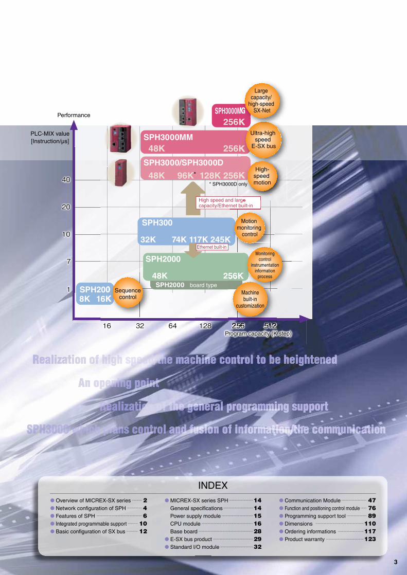
SPH3000/SPH3000D
SPH3000MM
SPH3000MG
SPH2000
High speed and large capacity/Ethernet built-in
Ethernet built-in
256K
48K 256K
48K 96K* 128K 256K
32K 74K 117K 245K
48K 256K
8K 16K
board type
Ultra-high speed
E-SX bus
High-speedmotion
Motionmonitoring
control
Performance
* SPH3000D only
PLC-MIX value
[Instruction/μs]
Large capacity/
high-speedSX-Net
Machinebuilt-in
customization
Sequencecontrol
Monitoring control
instrumentation information
process
Program capacity (K step)
INDEX
Overview of MICREX-SX series 2
Network configuration of SPH 4
Features of SPH 6
Integrated programmable support 10
Basic configuration of SX bus 12
MICREX-SX series SPH 14
General specifications 14
Power supply module 15
CPU module 16
Base board 28
E-SX bus product 29
Standard I/O module 32
Communication Module 47
Function and positioning control module 76
Programming support tool 89
Dimensions 110
Ordering informations 117
Product warranty 123
3

SX Bus Diverse Network Systems
Enabling Seamless Access
Open network at the FA application
type controller level established by
the Japan Electrical Manufacturers
Association. Allows inter-connec-
tion with PLC, CNC, and robots
beyond the frame of a single
manufacturer. The communication
physical layer employs Ethernet.
FL-netLONWORKS PROFIBUS-DP
Device-level open network
established by the EN50170
European standard. It best suits
time-critical applications between
an automation system and
distributed devices (remote I/O,
inverters, etc.).
Internationally noticeable open network
for building management. System
configuration as a device with distribut-
ed autonomous functions is enabled by
the control functions incorporated in site
devices. Replacement, update,
addition, and removal of site devices
can easily be performed.
Ethernet
POD I/O terminal
I/O terminal
Area controller/gateway
Servo system Extension unit Temperature
controller
LONWORKS
Proximity
switch
Ultrasonic
switch
Devices of other
manufacturers
Bit level network
AS-i
Controller level network
FL-net
Device level network DeviceNet
OPCN-1
PROFIBUS-DP
Open network group
4

DeviceNetOPCN-1 AS-i
Device-level open network
established by Japan Electrical
Manufacturers Association. Allows
connection with PLC and robots
using the same signal line beyond
the frame of a single manufacturer,
very effective in open system
improvement and optimization.
Open device-level network which
facilitates inter-connection of
control equipment such as PLCs,
personal computers, sensors, and
actuators. Wiring cost reduction by
minimizing wiring, and multi-vendor
equipment connection simplify an
economical system configuration.
Bit level network enacted to
IEC62026 and EN50295. AS-i is
suitable for distributing intelligent
input device such as proximity
switch, optoelectronic switch, push
button and ultrasonic sensor.
POD
P/PE-link
MICREX-NX series
MICREX-F series
Servo system
FUJI controllers
I/O terminal
Temperature
controller
Inverter
I/O terminal Inverter POD
Inverter
SX-Net
SPH3000MG SPH3000MM
E-SX-bus compatible devices
SX-bus compatible devices
T-link compatible devices
Servo system
Original network group
High-speed process and distributed arrangement of the E-SX bus and
the SX bus allow seamless connections with control indicators and
inverter servos. Various open network systems such from a small-
scale application built in a machine to a hierarchical distributed system
of large-scale line and facility devices can be constructed.
5

Realizes High-Speed Advanced Machine Control
1 ms scan
· Program scan time of 1ms is implemented by increased in-
struction processing speed.
· Real number operation and high-precision positioning con-
trol have been put to practical use by dramatically improved
floating-point operation speed.
1 ms I/O refreshing
· 1024 points of I/O is refreshed in 1 ms
· Tact control assures a fixed I/O refresh interval. The I/O re-
fresh cycle can be set to 1 ms, 2 ms, or up to 10 ms, which
is suitable for processing requiring strict tact time.
· The minimum tact times of SPH3000MM, SPH300, and
SPH2000/SPH3000 can be set at 0.25 ms, 0.5 ms, and
1 ms, respectively.
Ultra-high-speed 1 ms controller
Controller conforms to International Standard
Tact cycle
SPH3000 (D) SPH300 SPH2000 SPH200
Basic instruction LD 9 ns 20 ns 30 ns 70 ns
MOV 8 ns 40 ns 40 ns 140 ns
FloatingOperation instruction
88 ns 80 ns 270 ns to 56000 to
* For details on each instruction word's processing speed and tact cycle, see the User's Manual (FEH200).
Operating timing
Output
Message MessageDatacollection
Datadistribution
Datacollection
Datacollection
Datadistribution
Input
Tact cycle
1, 2, ……10 ms
Programcalculation Output
I/O refreshing
Input Programcalculation Output
I/O refreshingInternal Processor
SX bus
Conforms to IEC 61131 international standard
· Both the hardware and software conform to the IEC 61131 international standard for programmable controllers.
· The programming language conforms to the IEC 61131-3 international standard.
Conforming to international standard · Conforms to the CE marking, UL standards and RoHS direc-
tive (conforming one after another) as well as IEC standard.
· It also complies with the NK marine standard (Japan) and
the LR (specifications of Lloyd’s Register of Shipping, UK).
SX bus
Tact cycle 0.25 ms 0.375 ms 0.5 ms 1 ms 1.5 ms 2 ms
Max. I/O size - - 64 words 128 words 256 words 512 words
E-SX bus
Tact cycle 0.25 ms 0.375 ms 0.5 ms 1 ms 1.5 ms 2 ms
Max. I/O size 4 stations 67 words 256 words 512 words 2048 words 2048 words 4096 words
(Number of I/O stations) 16 stations - - 256 words 1024 words 1024 words 1024 words
32 stations - - - 512 words 2048 words 2048 words
64 stations - - - - 512 words 1024 words
ULJIS
NK
IEC
CE
LR
RoHS
6

Programmable Controller
Parallel processing with up to 8 CPUs (SPH300/SPH2000/SPH3000)
· Alleviates the load for each CPU allowing high-speed pro-
cessing of a large application program. For example, the
load can be distributed for advanced processing and se-
quence control processing with additional CPUs. I/O refresh
control is performed automatically even if parallel process-
ing by multiple CPUs is performed.
Multi-CPU system applicable to up to 8 CPUs
Redundant System Brings System Safety and Reliability
Note 1: The model that supports SPH2000 is NP1PM-256H.
Note 2: For a redundancy configuration buildup with a DC power supply, contact our
sales section.
Backup system
Memory card interface module NP1F-MM1
Active system
Backup system
Normalprocessing
time of asingle CPU CPU-1
Processing time
CPU-2
Processing time
CPU3
Processing time
CPU-4
Processing time
Common processing time
Figure illustrating reduced processing time for parallel operations by 4 units of CPUs
1:1 warm-standby feature (SPH300/SPH2000)
· This redundancy configuration enables continued operation
without system downtime if a CPU fails. (Control may tem-
porarily stop due to fault detection and CPU changeover.)
· The same program is stored in CPUs for the active and
backup systems, allowing constant data value equalization.
N:1 cold-standby feature (SPH300)
· N:1 backup feature enables reduction of the number of
standby system CPUs to one, though when a CPU fails,
data retained in the active system and that in the standby
system are not equalized.
· Data retained by the active system is not taken over. The
backup system CPU performs initial start.
Active system Backup system
Warm standby redundancy
configuration with up to 4
CPU sets is possible.
· Programs can be intensively controlled by a memory card.
Programs for N units of systems can be stored on a memory
card, which is installed in the memory card interface module
for centralized control of the programs. The same process-
ing programs as on the down CPU are downloaded to the
backup system CPU.
SX bus
CPU with error occurrence No. 3 CPU program downloading
ActivesystemCPU-1
ActivesystemCPU-2
ActivesystemCPU-3
MemorycardI/F
module
Memory cardBackupsystemCPU
No. 1 CPU program
No. 2 CPU program
No. 3 CPU program
Active system
Backup system
Active system
Max. 8 CPUs
7
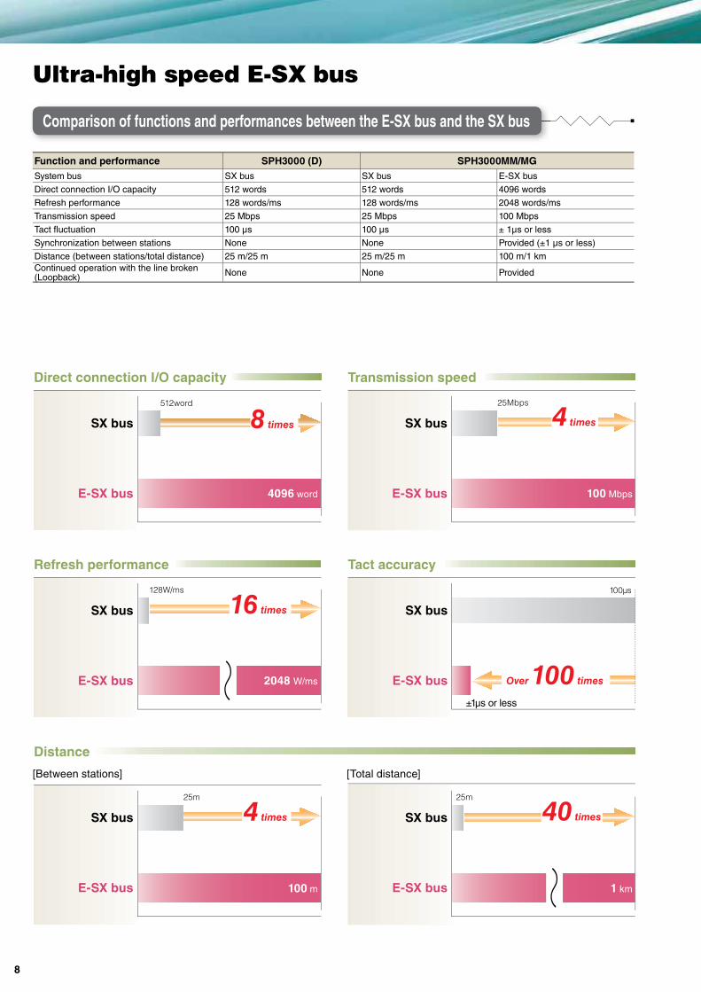
Ultra-high speed E-SX bus
Comparison of functions and performances between the E-SX bus and the SX bus
Direct connection I/O capacity Transmission speed
SX bus
E-SX bus
512word 25Mbps
Refresh performance Tact accuracy
128W/ms 100μs
±1μs or less
Distance
[Between stations] [Total distance]
25m 25m
SX bus
E-SX bus
SX bus
E-SX bus
SX bus
E-SX bus
SX bus
E-SX bus
SX bus
E-SX bus
16 times
4 times
~
~
4096 word 100 Mbps
2048 W/ms
100 m 1 km
Over 100 times
40 times
4 times8 times
Function and performance SPH3000 (D) SPH3000MM/MG
System bus SX bus SX bus E-SX bus
Direct connection I/O capacity 512 words 512 words 4096 words
Refresh performance 128 words/ms 128 words/ms 2048 words/ms
Transmission speed 25 Mbps 25 Mbps 100 Mbps
Tact fluctuation 100 μs 100 μs ± 1μs or less
Synchronization between stations None None Provided (±1 µs or less)
Distance (between stations/total distance) 25 m/25 m 25 m/25 m 100 m/1 km
Continued operation with the line broken(Loopback)
None None Provided
8

Programmable Controller
Synchronization in the busData output timing is synchronized in the
E-SX bus.
Loopback function
Communication is continued by the signal repeater
function even when a wire is broken.
Signal bypass function
Even when a power of some devices is not turned
on, the communication is continued by the auxiliary
power unit.
Synchronization between buses
Data output timing is synchronized between
channels of the E-SX bus.
Synchronization performance
± 1μs or less
Synchronization performance
±3 μs or less
E-SX bus
Inverter VG Inverter VG Inverter VG
Operation command value
Channel 0 operation command value
Inverter VG Inverter VG Inverter VG
Inverter VG Inverter VG Inverter VG
Channel 0 E-SX bus
Channel 1 E-SX bus
Channel 1 operation command value
Communication continuation
Communication continuation24 V DC power
supply
Auxiliary power
supply unit
E-SX bus
Inverter VGInverter VG
I/O terminal
The power of the device is Off.
The power of the device is Off.
I/O terminal
Synchronization control of E-SX bus
Connection function of the E-SX bus
Wire break!Communication continuation
Inverter VG Inverter VG
I/O terminal
E-SX bus
9

These are Windows-compatible programming support tools
conforming to the IEC61131-3 International Standard.
Improves Programming Development Efciency
Excellent documentation function
· The documentation preparation function has been substantially
improved. Not only can it print drawing numbers, dates, page,
and drawing borders, but also company logos and comments.
Simulation function
· This tool enables program test runs using the simulation func-
tion built in Expert (D300win), without using the actual unit.
Function module support function/ POD coop-eration function· The Expert (D300win) has implemented function module
support and POD cooperation support functions as com-
mon support tools.
· The function module support can be operated with the pro-
gramming supporting tool connecting CPU module.
Improvement of software development efficiencyProgramming in units of POU or worksheets allows the use of the structured design method by which a program is cre-ated by dividing it by functionality or process. This method enables multiple designers to divide the program design among them so that a substantial reduction in the program creation time can be achieved.
Programming of the same techniques as those of microcomputers and personal computersThe ST language is similar to the C language so that pro-grams can be created using the same techniques as those of microcomputers and personal computers for complex calculations that are hard to implement using the Ladder language. Programs and circuits that are frequently used can easily be reused by making them FB (function blocks).
Usage
Writing in multiple languages
· The Expert (D300win) completely supports five types of pro-
gram representations specified by the standards.
· It allows the programmer to code the proper combination of
representations for the control target.
Supported representations
IL (Instruction List)
LD (Ladder Diagram)
FBD (Function Block Diagram)
ST (Structured Text)
SFC (Sequential Function Chart)
Features
Development Efficiency Oriented Support ToolsExpert (D300win)
SX-Programmer
Two Types of Programming Support Tools in Accordance with Development Style
10
Programmable Controller
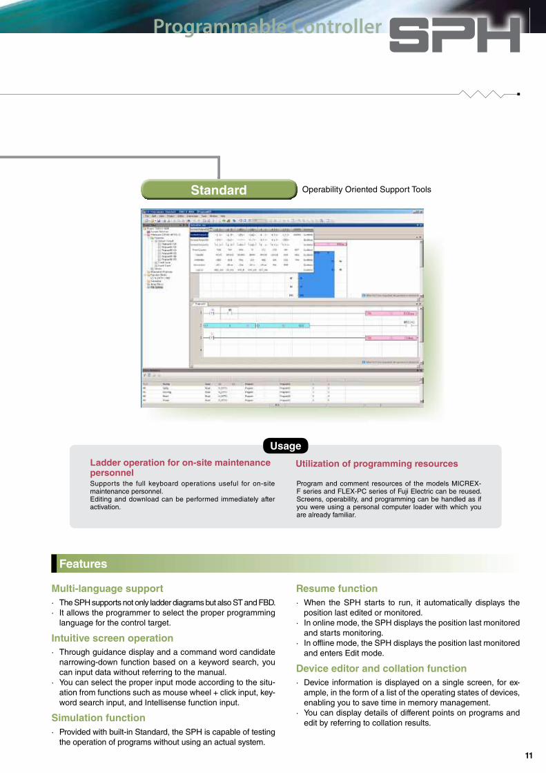
Multi-language support
· The SPH supports not only ladder diagrams but also ST and FBD.
· It allows the programmer to select the proper programming
language for the control target.
Intuitive screen operation
· Through guidance display and a command word candidate
narrowing-down function based on a keyword search, you
can input data without referring to the manual.
· You can select the proper input mode according to the situ-
ation from functions such as mouse wheel + click input, key-
word search input, and Intellisense function input.
Simulation function
· Provided with built-in Standard, the SPH is capable of testing
the operation of programs without using an actual system.
Device editor and collation function
· Device information is displayed on a single screen, for ex-
ample, in the form of a list of the operating states of devices,
enabling you to save time in memory management.
· You can display details of different points on programs and
edit by referring to collation results.
Resume function
· When the SPH starts to run, it automatically displays the
position last edited or monitored.
· In online mode, the SPH displays the position last monitored
and starts monitoring.
· In offline mode, the SPH displays the position last monitored
and enters Edit mode.
Ladder operation for on-site maintenance personnelSupports the full keyboard operations useful for on-site maintenance personnel.Editing and download can be performed immediately after activation.
Utilization of programming resources
Program and comment resources of the models MICREX-F series and FLEX-PC series of Fuji Electric can be reused. Screens, operability, and programming can be handled as if you were using a personal computer loader with which you are already familiar.
Features
Operability Oriented Support ToolsStandard
Usage
11

SX bus implements connecting max. 254
modules.The number of modules that can be connected to the SX
bus is a max. of 254 units. CPU modules, the communication
modules, the positioning modules, the function modules, and
the standard I/O modules can be connected up to 254 units.
Distributed placement is enabled by SX bus-
es extended up to 25 m in total.
Up to 25 extension base boards, PODs, and other SX-bus-based devices
can be connected within 25 m. (Up to 25.6 km for optical transmission)
Free topology is implemented by T-branches.
Use of T branches allows detailed, distributed installation of
the SX bus. Expansion units and diverse equipment arranged
in a tree structure can be connected in the optimum way.
Ultra-high-speed SX bus preserves distributed installation and expandability up to 254-module direct bus connection.
SX Bus Meets Diverse Demands for System Extension
Basic configuration of SX bus
Other connection notes· Be sure to install the power supply module and at least one module other than the power supply module to the left of each base board.
· Up to 25 base boards including the T-branch unit can be connected.
· Basically, base boards (power supply) in one configuration should be turned ON at one time. However, if it is necessary to turn OFF
some base boards (power supply) for application convenience, up to 3 continuous base boards can be turned OFF in one configuration.
Type of System Configuration
Module Type
Type A Type B Type C
· OPCN-1 master module (NP1L-JP1) · Web module (NP1L-WE1)
All modules other than
those of Type A and B
* The AS-i master module is
also included in category
C.
· OPCN-1 slave module (NP1L-JS1) · Ethernet module (NP1L-ET1)
· DeviceNet master module (NP1L-DN1) · FL-net module (NP1L-FL3)
· DeviceNet slave module (NP1L-DS1) · P-link module (NP1L-PL1)
· PROFIBUS-DP master module (NP1L-PD1) · PE-link module (NP1L-PE1)
· PROFIBUS-DP slave module (NP1L-PS1) · LE-net module (NP1L-LE1)
· T-link master module (NP1L-TL1) · LE-net loop2 module (NP1L-LL2)
· T-link slave module (NP1L-TS1) · General purpose communication module (NP1L-RS1/RS2/RS3/RS4/RS5)
· Remote terminal master/slave module (NP1L-RM1) · Memory card I/F module (NP1L-MM1)
No. of connectable base boards/units
Unit for supplying SX bus transmission power Unit for receiving SX bus transmission power
· Base board (power ON) · I/O terminal
· SX bus optical converter (external 24 V connected) · SX bus optical converter (external 24 V not connected)
· SX bus electrical repeater (external 24 V connected) · MONITOUCH V8 series (POD)
· PCI-bus-based high performance CPU board (built in personal computer)
· AC servo FALDIC- /ALPHA5 series
· Base board (power OFF) equivalent to 3 units above
Note: Up to 10 units for receiving SX bus transmission power can be continuously connected to each of the IN and OUT connectors of the unit for supplying SX bus transmission power.
Limit of modules connected in single configuration
Module Type Max. connected units
Power supply module Not limited in the number of power supply modules to be connected.
CPU module 8 units (1 unit for the SPH200)
Processor link module Total of 8 units of FL-net modules, P/PE-link modules and LE-net/LE-net loop 2 modules. (A total of 2 units of SPH200.)
Type A module 8 units (remote I/O master module)*
Type B module A total of 16 units including the SX bus communication unit of POD.
Type C module 238 units including Type A and B connected modules (excluding processor link modules and AS-i master module)
Note: For more information, refer to each manual.
* Each remote I/O master module has, in addition to the normal mode, the following two modes:
Extension mode: Function to extend the total number of input/output words of devices that can be connected to one master module unit from a maximum of 128 words (2048 points)
to a maximum of 512 words (8192 points) (extended to a maximum of 510 words for the PROFIBUS-DP master). However, the total number of input/output words
for one CPU unit is a max. of 512 words, which is equal to a total of the number of input/output words of the SX bus and that of the remote I/O master module.
I/O extension mode: I/O extension mode: Function to extend, in addition to the extension mode, the total number of input/output words of devices that can be connected to one
CPU unit from a max. of 512 words (8192 points) to a max. of 4096 words (65536 points). This mode is used when the total number of input/output words ex-
ceeds 512 words by connecting multiple remote I/O mater modules to one CPU unit. (Note that, by using this function, the input/output response time becomes
longer in proportion to the number of mounted remote I/O master modules.)
12
13
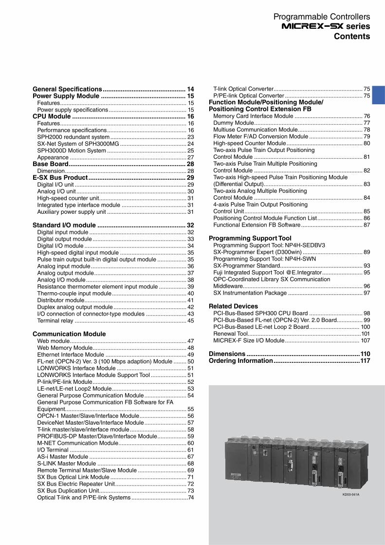
Contents
Programmable Controllers series
General Specifications.............................................. 14Power Supply Module ............................................... 15
Features.............................................................................. 15Power supply specifications................................................ 15
CPU Module ............................................................... 16Features.............................................................................. 16Performance specifications................................................. 16SPH2000 redundant system............................................... 23SX-Net System of SPH3000MG ......................................... 24SPH3000D Motion System ................................................. 25Appearance ........................................................................ 27
Base Board................................................................. 28Dimension........................................................................... 28
E-SX Bus Product...................................................... 29Digital I/O unit ..................................................................... 29Analog I/O unit .................................................................... 30High-speed counter unit...................................................... 31Integrated type interface module ........................................ 31Auxiliary power supply unit ................................................. 31
Standard I/O module ................................................. 32Digital input module ............................................................ 32Digital output module .......................................................... 33Digital I/O module ............................................................... 34High-speed digital input module ......................................... 35Pulse train output built-in digital output module .................. 35Analog input module........................................................... 36Analog output module......................................................... 37Analog I/O module.............................................................. 38Resistance thermometer element input module ................. 39Thermo-couple input module.............................................. 40Distributor module............................................................... 41Duplex analog output module ............................................. 42I/O connection of connector-type modules ......................... 43Terminal relay ..................................................................... 45
Communication ModuleWeb module........................................................................ 47Web Memory Module.......................................................... 48Ethernet Interface Module .................................................. 49FL-net (OPCN-2) Ver. 3 (100 Mbps adaption) Module ........ 50LONWORKS Interface Module ........................................... 51LONWORKS Interface Module Support Tool ...................... 51P-link/PE-link Module.......................................................... 52LE-net/LE-net Loop2 Module.............................................. 53General Purpose Communication Module.......................... 54General Purpose Communication FB Software for FA Equipment........................................................................... 55OPCN-1 Master/Slave/Interface Module............................. 56DeviceNet Master/Slave/Interface Module.......................... 57T-link master/slave/interface module................................... 58PROFIBUS-DP Master/Dlave/Interface Module.................. 59M-NET Communication Module.......................................... 60I/O Terminal ........................................................................ 61AS-i Master Module ............................................................ 67S-LINK Master Module ....................................................... 68Remote Terminal Master/Slave Module .............................. 69SX Bus Optical Link Module ............................................... 71SX Bus Electric Repeater Unit............................................ 72SX Bus Duplication Unit...................................................... 73Optical T-link and P/PE-link Systems ...................................74
T-link Optical Converter....................................................... 75P/PE-link Optical Converter ................................................ 75
Function Module/Positioning Module/Positioning Control Extension FB
Memory Card Interface Module .......................................... 76Dummy Module................................................................... 77Multiuse Communication Module........................................ 78Flow Meter F/AD Conversion Module ................................. 79High-speed Counter Module............................................... 80Two-axis Pulse Train Output Positioning Control Module ................................................................... 81Two-axis Pulse Train Multiple Positioning Control Module ................................................................... 82Two-axis High-speed Pulse Train Positioning Module (Differential Output)............................................................. 83Two-axis Analog Multiple Positioning Control Module ................................................................... 844-axis Pulse Train Output Positioning Control Unit......................................................................... 85Positioning Control Module Function List............................ 86Functional Extension FB Software...................................... 87
Programming Support ToolProgramming Support Tool: NP4H-SEDBV3 SX-Programmer Expert (D300win) ..................................... 89Programming Support Tool: NP4H-SWN SX-Programmer Standard................................................... 93Fuji Integrated Support Tool @E.Integrator......................... 95OPC-Coordinated Library SX Communication Middleware.......................................................................... 96SX Instrumentation Package .............................................. 97
Related DevicesPCI-Bus-Based SPH300 CPU Board ................................. 98PCI-Bus-Based FL-net (OPCN-2) Ver. 2.0 Board................ 99PCI-Bus-Based LE-net Loop 2 Board............................... 100Renewal Tool......................................................................101MICREX-F Size I/O Module.............................................. 107
Dimensions ...............................................................110Ordering Information................................................117
KD03-041A

General specifications
IEC 61131-2
JIS B 3502
IEC 61000-4-2
JIS C 61000-4-2
IEC 61000-4-3
JIS C 61000-4-3
IEC 61000-4-4
JIS C 61000-4-4
IEC 61000-4-5
JIS C 61000-4-5
IEC 61000-4-6
JIS C 61000-4-6
IEC 61000-4-8
JIS C 61000-4-8
Item
Physical
environment
Mechanical
operating condition
Electrical
operating
condition
Structure
Cooling method
Operating ambient temperature
Storage temperature
Relative humidity
Contamination degree
Corrosion resistance
Operating altitude
Resistance to vibration
Resistance to shock
Electrostatic discharge
Radiative radio frequency
electromagnetic field
Fast transient burst
Surge
Radio frequency electromagnetic field
Conducted interference
Power frequency magnetic field
Square wave impulse noise
Specifications
0 to +55˚C
-25 to +70˚C
20 to 95%RH (without condensation)
Contamination degree 2 (free from conductive dust)
No corrosive gas is present, no organic solvent adhesion
Altitude of 2000 m or less (air pressure of 70 kPa or higher during transportation)
One amplitude: 0.15 mm, constant acceleration: 19.6 m/s2, 2 hours for each direction, 6 hours total
Peak acceleration: 147 m/s2, 3 times for each direction
Contact discharge ±6 kV
Aerial discharge ±8 kV
80 to 1000 MHz 10 V/m
1.4 to 2.0GHz 3 V/m
2.0 to 2.7GHz 1V/m
Power supply line and I/O signal line (AC non-shield line): ±2 kV
Communication line and I/O signal line (except for AC non-shielded line): ±1 kV
AC power supply: Common mode ±2 kV, normal mode: ±1 kV
DC power supply: Common mode ±0.5 kV, normal mode: ±0.5 kV
150 kHz to 80 MHz, 10 V
50 Hz, 30 A/m
±1.5 kV, 1ns rising edge, 1 μs pulse width, 50 Hz
Open Type device (Built-in control panel type)
Natural cooling
14
General Specifications
Programmable Controllers series

Power supply specifications
Item
Model
Rated input voltage
Voltage tolerance
Rated frequency
Dropout tolerance
AC waveform distortion factor
Ripple factor tolerance
Leakage current
Inrush current
Power consumption
Rated output voltage
Output current
Insulation method
Dielectric strength
Insulation resistance
No. of occupied slots
Alarm output
Multiple power supply
Weight
Specifications
NP1S-22
100 to 120/200 to 240 V AC
85 to 132 V AC, 170 to 264 V AC
50/60 Hz
1 cycle or less
(Rated voltage, rated load)
5% or less
—
0.25mA or less
22.5 Ao-p or less (ambient temperature = 25˚C not repeated)
110 VA or less
24 V DC (22.8 to 26.4 V DC)
0 to 1.46 A
Transducer
2300 V AC, 1 minute
Between power input terminal and ground
10 MΩ or more with 500 V DC megger
2 slots
Relay NC contact output (Monitoring of output voltage: 24 V DC, 0.3 A or less)
Compatible (Up to 3 units mountable on the base board.)
Approx. 360 g
NP1S-42
24 V DC
19.2 to 30V DC
—
10 ms or less
(Rated voltage, rated load)
—
Three-phase full-wave rectification 5% or less
150 Ao-p or less 2 ms or less
45 W or less
510 V AC, 1 minute
Between power input terminal and ground
NP1S-91
100 to 120 V AC
85 to 132 V AC
40 VA or less
NP1S-81
200 to 240 V AC
170 to 264 V AC
50/60 Hz
1 cycle or less
(Rated voltage, rated load)
5% or less
-
22.5 Ao-p or less (ambient temperature = 25˚C not repeated)
50 VA or less
0 to 0.625 A
2300 V AC, 1 minute
Between power input terminal and ground
1 slot (specialized for the 3-slot and 6-slot basis)
None
Approx. 180 g
1400 V AC, 1 minute
Between power input terminal and ground
NP1S-91(Picture No. KD03-057A)
NP1S-22/NP1S-42
Power supply module: NP1S-
Features
Power supply module redundancy (NP1S-22/NP1S-42)Redundancy of the power supply has been realized by supplying the power from multiple (up to 3) power supply modules. Redundant power supply units allow you to improve system reliability.Small capacity power supply module (NP1S-81/NP1S-91)The use of the 100 V AC or 200 V AC small capacity power supply module (single slot) on a 3-slot and 6-slot basis allows effective use of one slot.
15
Power Supply Module
Programmable Controllers series

Redundancy (SPH300/SPH2000)1:1 warm-standby feature and N:1 backup feature improves the system safety and reliability.(N:1 backup feature is supported only by SPH300.)IEC 61131-3Complete compliance with the IEC 61131-3 international standard language This enables results of programming to be comprehended worldwide.
CPU module: NP1P -
Features
Ultra-high-speed processingRegarding the basic instructions, the CPU module carries out ultra-high-speed processing as below:SPH3000MG: 6 ns SPH3000/SPH3000MM: 9 nsSPH300: 20 ns SPH2000: 30 ns SPH200: 70 nsMulti CPU configuration (SPH200 excluded)Up to 8 CPUs can be configured. High-speed control is performed through load distribution.
Performance specifications
SPH300 SPH300EX
Model NP1PS-32 NP1PS-32R NP1PS-74R NP1PS-117R NP1PS-245R NP1PS-74D
Control system Stored programCyclic scanning system (default task), periodic task, event task
I/O connection method Direct connection I/O (SX bus), remote I/O (DeviceNet, OPCN-1, and other remote I/O links)
I/O control system SX bus: Tact synchronization refresh.Remote I/O link: Refresh by a remote master at 10-ms fixed intervals (not synchronized with scan)
CPU 32-bit OS processor, 32-bit execution processor
Programming language IEC 61131-3 conformedIL language (Instruction List), ST language (Structured Text), LD language (Ladder Diagram) FBD language (Function Block Diagram),SFC element (Sequential Function Chart)
Instruction execution speed
Sequenceinstruction
20 ns or more/instruction
Applied instruction 40 ns or more/instruction
No. of I/O points 8,192 points
User memory 97 Kwords 277 Kwords 491 Kwords 1,003 Kwords 277×2+6 Kwords
Program memory 65,536 words 151,552 words 239,616 words 501,760 words 151,552×2 words
32,768 steps 75,776 steps 119,808 steps 250,880 steps 75,776×2 steps
Data memory 33,792 words 132,096 words 263,168 words 525,312 words 132,096 × 2 + 6,144 words
Available basic data type *1 BOOL, INT, DINT, UINT, UDINT, REAL, TIME, DATE, TOD, DT, STRING, WORD, DWORD
Number of tasks *2 Default tasks (Cyclic scanning): 1Periodic task : 4Event tasks : 4
The tasks shown to the left are available to each of the basic CPU and extension CPU.
No. of POUs in program 2000 (including POUs in the library)
Interface*2
User ROM card(CF/SD)
-CF CARD CF CARD CF CARD CF CARD CF CARD
USB *3 -
Ethernet *4 - - - - - -
Diagnostic function Self-diagnosis (memory check, ROM sum check), system configuration monitoring, module fault monitoring
Security function Set limits to download/upload of the projects, reference, and clear etc., by the password.
Calendar Up to 31 Dec. 2069 23:59:59 Precision : 27sec/month (when active)When multi-CPU system is used, time is synchronized.
Battery backup *6 Backup range: Data memory, calendar IC memory, RAS areaBattery used: Lithium primary batteryBackup time (at 25˚C) NP1PS-32/32R: 5 years
NP1PS-74R/117R: Approx. 1.3 yearsNP1PS-245R: Approx. 0.7 yearsNP1PS-74D: Approx. 0.65 years
Replacement time (at 25°C): within 5 minutes
Memory backup by flash memory Application programs, system definitions, and ZIP files can be saved in the flash memory built in the CPU.
Memory backup by user ROM card (optional)
Application programs, system definitions, zip files, compressed projects and User's data can be saved in user ROM card (compact flash card).
No. of occupied slots 1 slot 2 slots
Internal current consumption 24 V DC, 200 mA or less
Weight Approx. 200 g Approx. 220 g Approx. 410 g
Using the optionally available large-capacity battery makes the backup time two to three times longer.
Up to 4 in total
*1 This depends on each instruction.*2 : Standard component -: Not equipped*3 Specifications of USB (The USB is to be used exclusively for programming support tools.)
Applicable standard of USB: USB1.1USB connector: USB-B type (NP1PS-32R/75D/74R/117R/245R), USB-miniB type (NP1PM-48R/48E/256E/256H, NP1PU-048E/128E/256E, NP1PUP-048, NP1PU2-
048E/256E, NP1PU1-256NE).
16
CPU Module
Programmable Controllers series
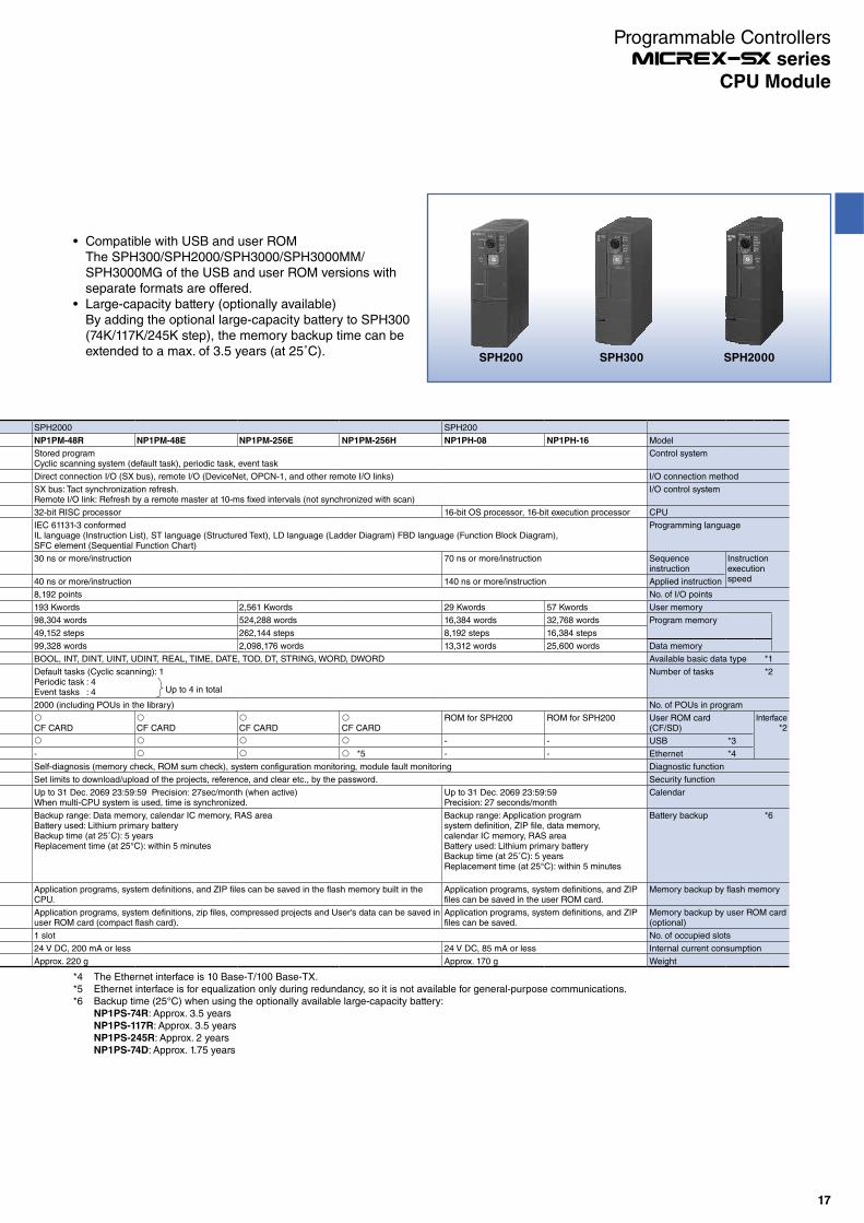
Compatible with USB and user ROMThe SPH300/SPH2000/SPH3000/SPH3000MM/SPH3000MG of the USB and user ROM versions with separate formats are offered.Large-capacity battery (optionally available)By adding the optional large-capacity battery to SPH300 (74K/117K/245K step), the memory backup time can be extended to a max. of 3.5 years (at 25˚C).
*4 The Ethernet interface is 10 Base-T/100 Base-TX.*5 Ethernet interface is for equalization only during redundancy, so it is not available for general-purpose communications.*6 Backup time (25°C) when using the optionally available large-capacity battery:
NP1PS-74R: Approx. 3.5 yearsNP1PS-117R: Approx. 3.5 yearsNP1PS-245R: Approx. 2 yearsNP1PS-74D: Approx. 1.75 years
SPH200 SPH300 SPH2000
Up to 4 in total
SPH2000 SPH200
NP1PM-48R NP1PM-48E NP1PM-256E NP1PM-256H NP1PH-08 NP1PH-16 Model
Stored programCyclic scanning system (default task), periodic task, event task
Control system
Direct connection I/O (SX bus), remote I/O (DeviceNet, OPCN-1, and other remote I/O links) I/O connection method
SX bus: Tact synchronization refresh.Remote I/O link: Refresh by a remote master at 10-ms fixed intervals (not synchronized with scan)
I/O control system
32-bit RISC processor 16-bit OS processor, 16-bit execution processor CPU
IEC 61131-3 conformedIL language (Instruction List), ST language (Structured Text), LD language (Ladder Diagram) FBD language (Function Block Diagram),SFC element (Sequential Function Chart)
Programming language
30 ns or more/instruction 70 ns or more/instruction Sequenceinstruction
Instruction execution speed40 ns or more/instruction 140 ns or more/instruction Applied instruction
8,192 points No. of I/O points
193 Kwords 2,561 Kwords 29 Kwords 57 Kwords User memory
98,304 words 524,288 words 16,384 words 32,768 words Program memory
49,152 steps 262,144 steps 8,192 steps 16,384 steps
99,328 words 2,098,176 words 13,312 words 25,600 words Data memory
BOOL, INT, DINT, UINT, UDINT, REAL, TIME, DATE, TOD, DT, STRING, WORD, DWORD Available basic data type *1
Default tasks (Cyclic scanning): 1Periodic task : 4Event tasks : 4
Number of tasks *2
2000 (including POUs in the library) No. of POUs in program
CF CARD CF CARD CF CARD CF CARDROM for SPH200 ROM for SPH200 User ROM card
(CF/SD)Interface
*2
- - USB *3
- *5 - - Ethernet *4
Self-diagnosis (memory check, ROM sum check), system configuration monitoring, module fault monitoring Diagnostic function
Set limits to download/upload of the projects, reference, and clear etc., by the password. Security function
Up to 31 Dec. 2069 23:59:59 Precision: 27sec/month (when active)When multi-CPU system is used, time is synchronized.
Up to 31 Dec. 2069 23:59:59Precision: 27 seconds/month
Calendar
Backup range: Data memory, calendar IC memory, RAS areaBattery used: Lithium primary batteryBackup time (at 25˚C): 5 yearsReplacement time (at 25°C): within 5 minutes
Backup range: Application programsystem definition, ZIP file, data memory,calendar IC memory, RAS areaBattery used: Lithium primary batteryBackup time (at 25˚C): 5 yearsReplacement time (at 25°C): within 5 minutes
Battery backup *6
Application programs, system definitions, and ZIP files can be saved in the flash memory built in the CPU.
Application programs, system definitions, and ZIP files can be saved in the user ROM card.
Memory backup by flash memory
Application programs, system definitions, zip files, compressed projects and User's data can be saved in user ROM card (compact flash card).
Application programs, system definitions, and ZIP files can be saved.
Memory backup by user ROM card (optional)
1 slot No. of occupied slots
24 V DC, 200 mA or less 24 V DC, 85 mA or less Internal current consumption
Approx. 220 g Approx. 170 g Weight
17
CPU Module
Programmable Controllers series

Performance specifications
SPH3000 SPH3000D
Model NP1PU-048E NP1PU-128E NP1PU-256E NP1PU-048EZM NP1PU-096EZM NP1PU-0128EZM NP1PU-256EZM
Control system Stored programCyclic scanning system (default task), periodic task, event task
I/O connection method Direct connection I/O (SX bus), remote I/O (DeviceNet, OPCN-1, and other remote I/O links)
I/O control system SX bus: Tact synchronization refresh.Remote I/O link: Refresh by a remote master at 10-ms fixed intervals (not synchronized with scan)
CPU 32-bit RISC processor
Programming language IEC 61131-3 conformedIL language (Instruction List), ST language (Structured Text), LD language (Ladder Diagram) FBD language (Function Block Diagram),SFC element (Sequential Function Chart)
Instruction execution speed
Sequenceinstruction
9 ns or more/instruction
Appliedinstruction
8 ns or more/instruction
No. of I/O points 8,192 points
SX bus 8,192 points
E-SX bus0/E-SX bus1 -
User memory 353 Kwords 1,281 Kwords 2,561 Kwords 545 Kwords 1,409 Kwords 1,473 Kwords 2,753 Kwords
Program memory 98,304 words 262.144 words 524,288 words 98,304 words 196,608 words 262,144 words 524,288 words
49,152 steps 131,072 steps 262,144 steps 49,152 steps 98,304 steps 131,072 steps 262,144 steps
SX bus 98,304 words 262,144 words 524,288 words 98,304 words 196,608 words 262,144 words 524,288 words
49,152 steps 131,072 steps 262,144 steps 49,152 steps 98,304 steps 131,072 steps 242,144 steps
E-SX bus0/E-SX bus1 -
-
Data memory 263,168 words 1,049,600 words 2,098,176 words 459,776 words 1,246,208 words 1,246,208 words 2,294,784 words
SX bus 263,168 words 1,049,600 words 2,098,176 words 459,776 words 1,246,208 words 1,246,208 words 2,294,784 words
E-SX bus0/E-SX bus1 -
Available basic data type *1 BOOL, INT, DINT, UINT, UDINT, REAL, TIME, DATE, TOD, DT, STRING, WORD, DWORD
Number of tasks *2 SX busDefault tasks (Cyclic scanning): 1Periodic task : 4Event tasks : 4
No. of POUs in program 2000 (including POUs in the library)
Interface User ROM card(CF/SD) SD memory card
USB *3
Ethernet *4
Diagnostic function Self-diagnosis (memory check, ROM sum check), system configuration monitoring, module fault monitoring
Security function Set limits to download/upload of the projects, reference, and clear etc., by the password.
Calendar Up to 31 Dec. 2069 23:59:59 Precision: 27sec/month (when active)When multi-CPU system is used, time is synchronized.
Battery backup Backup range: Data memory, calendar IC memory, RAS areaBattery used: Lithium primary batteryBackup time (at 25˚C): 5 yearsReplacement time (at 25°C): within 5 minutes
Memory backup by flash memory Application programs, system definitions, and ZIP files can be saved in the flash memory built in the CPU.
Memory backup by user ROM card (optional)
Application programs, system definitions, zip files, compressed projects and User's data can be saved in user ROM card (compact flash card).
No. of occupied slots 1 slot
Internal current consumption 24 V DC, 200 mA or less
Weight Approx. 220 g
Up to 4 in total
*1 This depends on each instruction.*2 SPH3000MM contains one SX bus and two E-SX buses. The number of tasks available to each of these buses is shown in the table.
SPH3000MG contains one SX bus and one E-SX bus. The number of tasks available to each of these buses is shown in the table.*3 Specifications of USB (The USB is to be used exclusively for programming support tools.)
Applicable standard of USB: USB1.1USB connector: USB-B type (NP1PS-32R/74D/74R/117R/245R), USB-miniB type (NP1PM-48R/48E/256E/256H, NP1PU-048EZM/096EZM/128EZM/256EZM,
NP1PUP-048, NP1PU2-048E/256E, NP1PU1-256NE).*4 The Ethernet interface is 10 Base-T/100 Base-TX (SPH3000, SPH3000D, SPH3000PN, SPH3000MM, SPH3000MG)
SPH3000DSPH3000MM SPH3000MG
18
CPU Module
Programmable Controllers series
Performance specifications
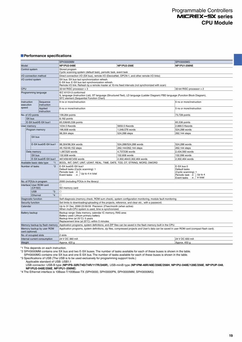
SPH3000MM SPH3000MG
Model NP1PU2-048E NP1PU2-256E NP1PU1-256NE
Control system Stored programCyclic scanning system (default task), periodic task, event task
I/O connection method Direct connection I/O (SX bus), remote I/O (DeviceNet, OPCN-1, and other remote I/O links)
I/O control system SX bus: SX bus tact synchronization refresh.E-SX bus: E-SX bus tact synchronization refresh.Remote I/O link: Refresh by a remote master at 10-ms fixed intervals (not synchronized with scan)
CPU 32-bit RISC processor × 3 32-bit RISC processor × 2
Programming language IEC 61131-3 conformedIL language (Instruction List), ST language (Structured Text), LD language (Ladder Diagram) FBD language (Function Block Diagram),SFC element (Sequential Function Chart)
Instruction execution speed
Sequenceinstruction
9 ns or more/instruction 6 ns or more/instruction
Appliedinstruction
8 ns or more/instruction 5 ns or more/instruction
No. of I/O points 139,264 points 73,728 points
SX bus 8,192 points
E-SX bus0/E-SX bus1 65,536/65,536 points 65,536 points
User memory 1234.5 Kwords 5650.5 Kwords 2,889.5 Kwords
Program memory 196,608 words 1,048,576 words 524,288 words
98,304 steps 524,288 steps 262,144 steps
SX bus -
-
E-SX bus0/E-SX bus1 98,304/98,304 words 524,288/524,288 words 524,288 words
49,152/49,152 steps 262,144/262,144 steps 262,144 steps
Data memory 1,067,520 words 4,737,536 words 2,434,560 words
SX bus 132,608 words 132,608 words 132,096 words
E-SX bus0/E-SX bus1 467,456/467,456 words 2,302,464/2,302,464 words 2,302,464 words
Available basic data type *1 BOOL, INT, DINT, UINT, UDINT, REAL, TIME, DATE, TOD, DT, STRING, WORD, DWORD
Number of tasks *2 E-SX bus0/E-SX bus1Default tasks (Cyclic scanning): 1Periodic task : 4Event tasks : 4
E-SX bus 0Default tasks (Cyclic scanning): 1Periodic task : 4Event tasks : 4
No. of POUs in program 2000 (including POUs in the library)
Interface User ROM card(CF/SD) SD memory card
USB *3
Ethernet *4
Diagnostic function Self-diagnosis (memory check, ROM sum check), system configuration monitoring, module fault monitoring
Security function Set limits to downloading/uploading of the projects, reference, and clear etc., with a password.
Calendar Up to 31 Dec. 2069 23:59:59 Precision: 27sec/month (when active)When multi-CPU system is used, time is synchronized.
Battery backup Backup range: Data memory, calendar IC memory, RAS areaBattery used: Lithium primary batteryBackup time (at 25˚C): 5 yearsReplacement time (at 25°C): within 5 minutes
Memory backup by flash memory Application programs, system definitions, and ZIP files can be saved in the flash memory built in the CPU.
Memory backup by user ROM card (optional)
Application programs, system definitions, zip files, compressed projects and User’s data can be saved in user ROM card (compact flash card).
No. of occupied slots 2 slots
Internal current consumption 24 V DC 360 mA 24 V DC 650 mA
Weight Approx. 420 g Approx. 450 g
*1 This depends on each instruction.*2 SPH3000MM contains one SX bus and two E-SX buses. The number of tasks available for each of these buses is shown in the table.
SPH3000MG contains one SX bus and one E-SX bus. The number of tasks available for each of these buses is shown in the table.*3 Specifications of USB (The USB is to be used exclusively for programming support tools.)
Applicable standard of USB: USB1.1USB connector: USB-B type (NP1PS-32R/74D/74R/117R/245R), USB-miniB type (NP1PM-48R/48E/256E/256H, NP1PU-048E/128E/256E, NP1PUP-048,NP1PU2-048E/256E, NP1PU1-256NE)
*4 The Ethernet interface is 10Base-T/100Base-TX (SPH3000, SPH3000PN, SPH3000MM, SPH3000MG)
Up to 4 in total Up to 4 in total
19
CPU Module
Programmable Controllers series

Performance specifications (user memory detail)
SPH300 SPH300EX
Model NP1PS-32 NP1PS-32R NP1PS-74R NP1PS-117R NP1PS-245R NP1PS-74D
User memory 97 Kwords 277 Kwords 491 Kwords 1,003 Kwords 277×2+6 Kwords
Program memory 65,536 words 151,552 words 239,616 words 501,760 words 151,552×2 words
32,768 steps 75,776 steps 119,808 steps 250,880 steps 75,776 × 2 steps
Data memory 33,792 words 132,096 words 263,168 words 525,312 words 132,096 × 2 + 6,144 words
I/O memory 512 words 512×2 words
Non-retain memory 8,192 words 32,768 words 131,072 words 262,144 words 32,768 × 2 words
Retain memory 4,096 words 16,384 words 32,768 words 130,048 words 16,384 × 2 words
User FB memory 4,096 words 16,384 words 32,768 words 66,560 words 16,384 × 2 words
System FB memory 16,384 words 65,536 words 65,536 × 2 words
Edge detection 1,024 points 4,096 points 4,096 x 2 points
Counter 256 points 1,024 points 1,024 x 2 points
Integrating timer 128 points 512 points 512 x 2 points
Timer 512 points 2,048 points 2,048 x 2 points
Others 8,192 words 32,768 words 32,768 × 2 words
System memory 512 words 512 × 2 words
Common memory - 6,144 words
SPH2000 SPH200
Model NP1PM-48R NP1PM-48E NP1PM-256E NP1PM-256H NP1PH-08 NP1PH-16
User memory 193 Kwords 2,561 Kwords 29 Kwords 57 Kwords
Program memory 98,304 words 524,288 words 16,384 words 32,768 words
49,152 steps 262,144 steps 8,192 steps 16,384 steps
Data memory 99,328 words 2,098,176 words 13,312 words 25,600 words
I/O memory 512 words
Non-retain memory 65,536 words 1,703,936 words 4,096 words 8,192 words
Retain memory 8,192 words 237,568 words 2,048 words 4,096 words
User FB memory 8,192 words 73,728 words 2,048 words 4,096 words
System FB memory 16,384 words 81,920 words 4,096 words 8,192 words
Edge detection 1,024 points 5,120 words 256 points 512 points
Counter 256 points 1,280 words 64 points 128 points
Integrating timer 128 points 640 words 32 points 64 points
Timer 512 points 2,560 words 128 points 256 points
Others 8,192 words 40,960 words 2,048 words 4,096 words
System memory 512 words
Common memory -
Note: Area sizes of the non-retain memory, the retain memory, the user FB memory and the system FB memory can be changed.
20
CPU Module
Programmable Controllers series
Performance specifications (user memory detail)
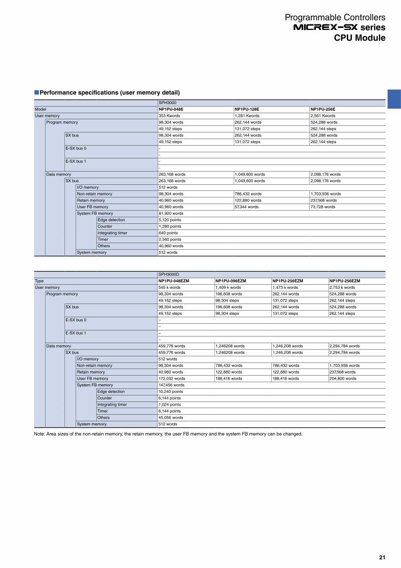
SPH3000
Model NP1PU-048E NP1PU-128E NP1PU-256E
User memory 353 Kwords 1,281 Kwords 2,561 Kwords
Program memory 98,304 words 262,144 words 524,288 words
49,152 steps 131,072 steps 262,144 steps
SX bus 98,304 words 262,144 words 524,288 words
49,152 steps 131,072 steps 262,144 steps
E-SX bus 0 -
-
E-SX bus 1 -
-
Data memory 263,168 words 1,049,600 words 2,098,176 words
SX bus 263,168 words 1,049,600 words 2,098,176 words
I/O memory 512 words
Non-retain memory 98,304 words 786,432 words 1,703,936 words
Retain memory 40,960 words 122,880 words 237,568 words
User FB memory 40,960 words 57,344 words 73,728 words
System FB memory 81,920 words
Edge detection 5,120 points
Counter 1,280 points
Integrating timer 640 points
Timer 2,560 points
Others 40,960 words
System memory 512 words
SPH3000D
Type NP1PU-048EZM NP1PU-096EZM NP1PU-256EZM NP1PU-256EZM
User memory 545 k words 1,409 k words 1,473 k words 2,753 k words
Program memory 98,304 words 196,608 words 262,144 words 524,288 words
49,152 steps 98,304 steps 131,072 steps 262,144 steps
SX bus 98,304 words 196,608 words 262,144 words 524,288 words
49,152 steps 98,304 steps 131,072 steps 262,144 steps
E-SX bus 0 –
–
E-SX bus 1 –
–
Data memory 459,776 words 1,246208 words 1,246,208 words 2,294,784 words
SX bus 459,776 words 1,246208 words 1,246,208 words 2,294,784 words
I/O memory 512 words
Non-retain memory 98,304 words 786,432 words 786,432 words 1,703,936 words
Retain memory 40,960 words 122,880 words 122,880 words 237,568 words
User FB memory 172,032 words 188,416 words 188,416 words 204,800 words
System FB memory 147,456 words
Edge detection 10,240 points
Counter 6,144 points
Integrating timer 1,024 points
Timer 6,144 points
Others 45,056 words
System memory 512 words
Note: Area sizes of the non-retain memory, the retain memory, the user FB memory and the system FB memory can be changed.
21
CPU Module
Programmable Controllers series

Performance specifications (user memory detail)
3000MM SPH3000MG
Model NP1PU2-048E NP1PU2-256E NP1PU1-256NE
User memory 1234.5 Kwords 5650.5 Kwords 2,889.5 Kwords
Program memory 196,608 words 1,048,576 words 524,288 words
98,304 steps 524,288 steps 262,144 steps
SX bus -
-
E-SX bus 0 98,304 words 524,288 words
49,152 steps 262,144 steps
E-SX bus 1 98,304 words 524,288 words -
49,152 steps 262,144 steps -
Data memory 1,067,520 words 4,737,536 words 2,434,560 words
SX bus 132,608 words 132,096 words
I/O memory 512 words
Non-retain memory 65,536 words
Retain memory 65,536 words
User FB memory -
System FB memory -
Edge detection -
Counter -
Integrating timer -
Timer -
Others -
System memory 512 words
Common memory 512 words -
E-SX bus 0 467,456 words 2,302,464 words
I/O memory 4,096 words
Non-retain memory 98,304 words 1,703,936 words
Retain memory 40,960 words 237,568 words
User FB memory 172,032 words 204,800 words
System FB memory 147,456 words
Edge detection 10,240 points
Counter 6,144 points
Integrating timer 1,024 points
Timer 6,144 points
Others 45,056 words
System memory 4,608 words
E-SX bus 1 467,456 words 2,302,464 words -
I/O memory 4,096 words -
Non-retain memory 98,304 words 1,703,936 words -
Retain memory 40,960 words 237,568 words -
User FB memory 172,032 words 204,800 words -
System FB memory 147,456 words -
Edge detection 10,240 points -
Counter 6,144 points -
Integrating timer 1,024 points -
Timer 6,144 points -
Others 45,056 words -
System memory 4,608 words -
Note: Area sizes of the non-retain memory, the retain memory, the user FB memory and the system FB memory can be changed.
22
Programmable Controllers series
CPU Module
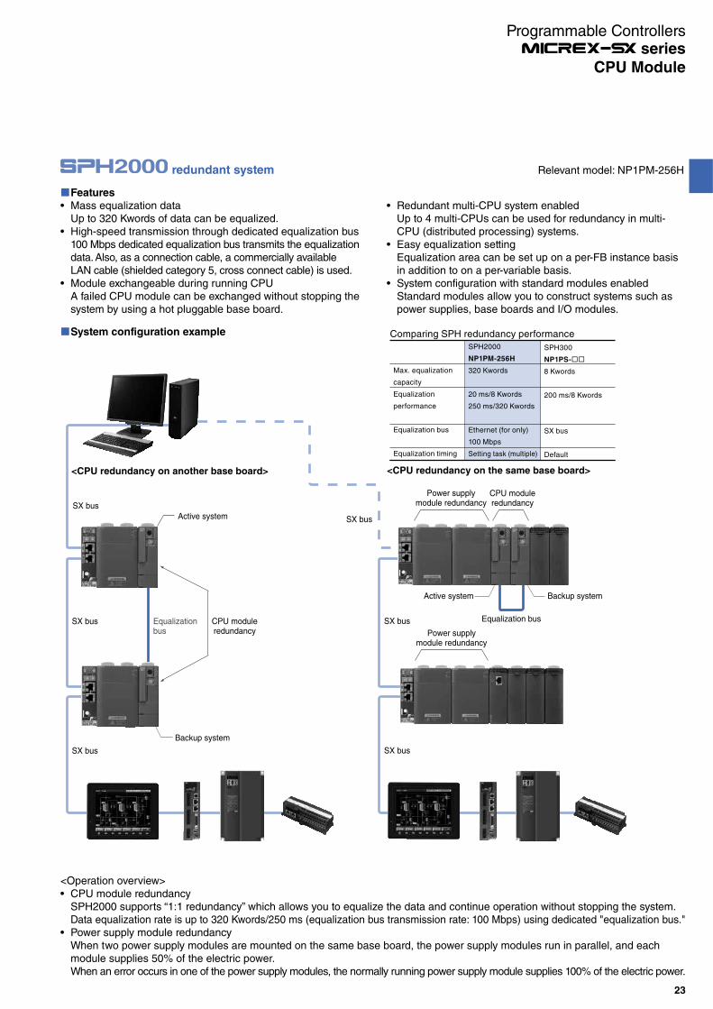
Features
Mass equalization dataUp to 320 Kwords of data can be equalized.High-speed transmission through dedicated equalization bus100 Mbps dedicated equalization bus transmits the equalization data. Also, as a connection cable, a commercially available LAN cable (shielded category 5, cross connect cable) is used.Module exchangeable during running CPUA failed CPU module can be exchanged without stopping the system by using a hot pluggable base board.
Redundant multi-CPU system enabledUp to 4 multi-CPUs can be used for redundancy in multi-CPU (distributed processing) systems.Easy equalization settingEqualization area can be set up on a per-FB instance basis in addition to on a per-variable basis.System configuration with standard modules enabledStandard modules allow you to construct systems such as power supplies, base boards and I/O modules.
<Operation overview>CPU module redundancySPH2000 supports “1:1 redundancy” which allows you to equalize the data and continue operation without stopping the system.Data equalization rate is up to 320 Kwords/250 ms (equalization bus transmission rate: 100 Mbps) using dedicated "equalization bus."Power supply module redundancyWhen two power supply modules are mounted on the same base board, the power supply modules run in parallel, and each module supplies 50% of the electric power.When an error occurs in one of the power supply modules, the normally running power supply module supplies 100% of the electric power.
System configuration example Comparing SPH redundancy performance
Max. equalization
capacity
Equalization
performance
Equalization bus
Equalization timing
SPH2000
NP1PM-256H
320 Kwords
20 ms/8 Kwords
250 ms/320 Kwords
Ethernet (for only)
100 Mbps
Setting task (multiple)
SPH300
NP1PS-
8 Kwords
200 ms/8 Kwords
SX bus
Default
Power supplymodule redundancy
CPU moduleredundancy
Power supplymodule redundancy
SX bus
SX bus
SX bus
SX bus
SX bus
SX bus
Equalization busEqualizationbus
Active system Backup system
Active system
Backup system
CPU moduleredundancy
<CPU redundancy on another base board> <CPU redundancy on the same base board>
redundant system Relevant model: NP1PM-256H
23
CPU Module
Programmable Controllers series

SX-Net specifications
Item Specifications
No. of connectable modules 126 units
Station number setting range 1 to 126
Scan interval 0.5 ms to 30 ms (0.5 ms steps)(This depends on the number of connected modules, distance, total data quantity, and the number of hubs.)
Common memory function
1-slot transmission size 512 W
1-slot transmission time 30 us
Maximum number of slots 256 slots
Data area size 128 KW (64 * 2048 blocks)
Area definition 64 W fixed-block selection method
Unit of data guarantee Unit of station occupation
Area update timing At the time of each scan (Batch transfer of area data)
Messagefunction
Type Unicast message (1 to 1)
Broadcast message (1 to N)
Size 1024 bytes
Features
Large scaleThe network enables 126 nodes to be connected per system.Large capacityThe network allows 128 Kwords (2,048 blocks in total in the unit of 64 words) as common memory space per system.
High speedThe settable shortest network scan interval is 0.5 ms (0.5 ms steps, up to 30 ms).
SX-Net is a controller level network based on gigabit Ethernet. It allows high-speed large-capacity communications.
System configuration example
SX-Net 1000BASE-T compatible switching hub
SX-Net system of SPH3000MG
24
CPU Module
Programmable Controllers series
25
CPU Module
Programmable Controllers series
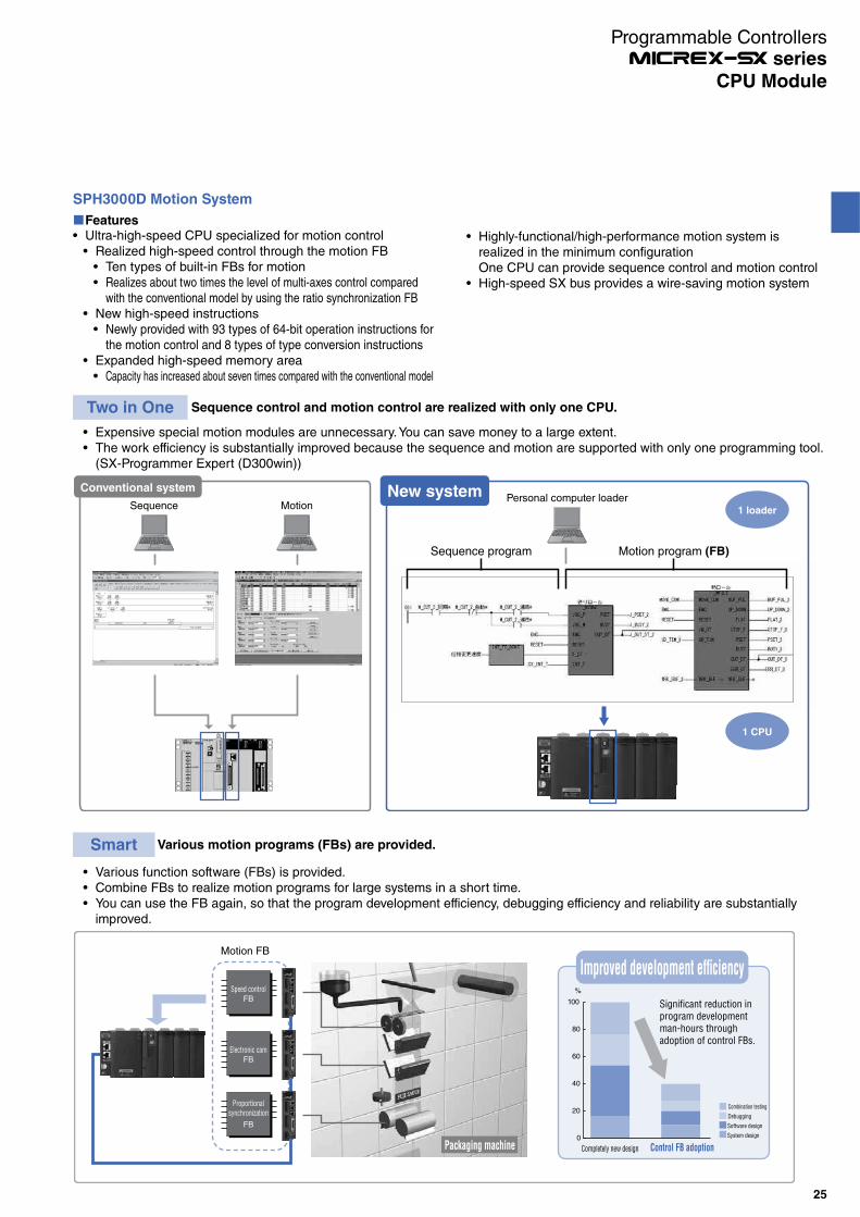
Expensive special motion modules are unnecessary. You can save money to a large extent.The work efficiency is substantially improved because the sequence and motion are supported with only one programming tool. (SX-Programmer Expert (D300win))
SPH3000D Motion System
FeaturesUltra-high-speed CPU specialized for motion control
Realized high-speed control through the motion FBTen types of built-in FBs for motionRealizes about two times the level of multi-axes control compared with the conventional model by using the ratio synchronization FB
New high-speed instructions Newly provided with 93 types of 64-bit operation instructions for the motion control and 8 types of type conversion instructions
Expanded high-speed memory areaCapacity has increased about seven times compared with the conventional model
Two in One Sequence control and motion control are realized with only one CPU.
Conventional system New systemSequence
Sequence program Motion program (FB)
MotionPersonal computer loader
1 loader
1 CPU
Highly-functional/high-performance motion system is realized in the minimum configurationOne CPU can provide sequence control and motion controlHigh-speed SX bus provides a wire-saving motion system
Various function software (FBs) is provided.Combine FBs to realize motion programs for large systems in a short time.You can use the FB again, so that the program development efficiency, debugging efficiency and reliability are substantially improved.
Smart Various motion programs (FBs) are provided.
Motion FB
Speed control
FB
Electronic cam
FB
Proportional
synchronization
FB
0
20
40
60
80
100 Significant reduction in
program development
man-hours through
adoption of control FBs.
Completely new design Control FB adoption
Combination testing
Debugging
Software design
System design
%
Packaging machine
Improved development efciency

26
CPU Module
Programmable Controllers series
The minimum command period is 1ms.The servo amplifier directly coupled to the SX bus helps establish a reduced wiring system.
Cumbersome I/O wiring work and faults caused by wiring are substantially reduced.Distributed installation of servo amplifiers is supported.Addition of a servo axis to the system is quick with the SX bus cable. (Modular connector)Due to serial bus compatibility, high level data control (such as operation status monitor and fault state monitor) can be realized.
Simple A high-speed serial bus system (SX bus: 25mbps) is adopted.
SX bus cable
200V power supply 200Vpower supply
200V power supply
Only one SX bus cable is necessary
for connection to the system.
Added
Overall length 25m (standard)
* With SX bus electric repeaters, max. 100m. With SX bus optical converters, max. 25.6km.
SPH3000D Motion System

Appearance
NP1PH-08/NP1PH-16) NP1PS-32R/NP1PS-74R/NP1PS-117R/NP1PS-245R)
NP1PM-48R/NP1PM-48E/NP1PM-256E/NP1PM-256H)
NP1PS-74D)
RUN
ALM
EX SX-BUS
OUT
ONL
ERR
32
DE
7
456
98
BCA
1F
0
LOADER
RUN
STOP BAT
No.CPU
UROMERR
ALMRUN
TERMUROM
ONL
32
DE
7
456
98
BCA
1F
0
LOADER
RUN
STOP BAT
No.CPU
UROMERR
ALMRUN
TERMUROM
ONL
32
DE
7
456
98
BCA
1F
0
LOADER
RUN
STOP BAT
No.CPU
UROMERR
ALMRUN
TERMUROM
ONL
NP1PU-048E/NP1PU-128E/NP1PU-256E)
****
**
IN
IN
NP1PU2-048E/NP1PU2-256E)
32
DE
7
456
98
BCA
1F
0
LOADER
RUN
STOP BAT
No.CPU
UROMERR
ALMRUN
TERMUROM
ONL
27
CPU Module
Programmable Controllers series

Base board: NP1B -
Name
Standard base board
High-performance base board
Standard base board with
station number setting switch
High-performance base board
with station number setting switch
Standard hot plug base board
with station number setting switch
Station number setting switch incorporated
high-performance hot plug base board
Base board 3 slots
Base board 6 slots
Base board 8 slots
Base board 11 slots
Base board 13 slots
Base board 13 slots
Base board 8 slots
Base board 11 slots
Base board 13 slots
Base board 13 slots
Base board 8 slots
Base board 11 slots
Base board 13 slots
Base board 13 slots
Model
NP1BS-03
NP1BS-06
NP1BS-08
NP1BS-11
NP1BS-13
NP1BP-13
NP1BS-08S
NP1BS-11S
NP1BS-13S
NP1BP-13S
NP1BS-08D
NP1BS-11D
NP1BS-13D
NP1BP-13D
Max. no. of modules
2 (Not include a power supply)
5 (Not include a power supply)
6 (Not include a power supply)
9 (Not include a power supply)
11 (Not include a power supply)
11 (Not include a power supply)
6 (Not include a power supply)
9 (Not include a power supply)
11 (Not include a power supply)
11 (Not include a power supply)
6 (Not include a power supply)
9 (Not include a power supply)
11 (Not include a power supply)
11 (Not include a power supply)
Remarks
SX bus 3 slots, processor bus 2 slots
SX bus 6 slots, processor bus 4 slots
SX bus 8 slots, processor bus 3 slots
SX bus 11 slots, processor bus 3 slots
SX bus 13 slots, processor bus 3 slots
SX bus 13 slots, processor bus 10 slots
SX bus 8 slots, processor bus 3 slots
SX bus 11 slots, processor bus 3 slots
SX bus 13 slots, processor bus 3 slots
SX bus 13 slots, processor bus 10 slots
SX bus 8 slots, processor bus 3 slots
SX bus 11 slots, processor bus 3 slots
SX bus 13 slots, processor bus 3 slots
SX bus 13 slots, processor bus 10 slots
Internal current consumption
35 mA or less
45 mA or less
50 mA or less
60 mA or less
70 mA or less
70 mA or less
60 mA or less
70 mA or less
80 mA or less
80 mA or less
70 mA or less
80 mA or less
80 mA or less
80 mA or less
Weight
Approx. 250 g
Approx. 420 g
Approx. 540 g
Approx. 720 g
Approx. 840 g
Approx. 840 g
Approx. 550 g
Approx. 730 g
Approx. 850 g
Approx. 850 g
Approx. 550 g
Approx. 730 g
Approx. 850 g
Approx. 850 g
Note: Mount a power supply module, plus not less than one module, onto the base board.Make sure to always mount the power supply module at the left side of the base board.A high-performance base board is used when configuring the system, such as one with multi-CPUs and redundancy, and it uses a processor bus heavily.Modules which use the processor bus are as follows:
· CPU module · FL-net module· P-link/PE-link module · LE-net related module
Dimension
*
* Station number setting switchIncorporated in base board with the station number setting switch
W2
W1
108
50
18.1
3
8
[Units: mm]
Note: When the connector is mounted, the depth is a max. of 195.3mm.The bracket is already mounted on the base board.
No. of slots
3
6
8
11
13
W1
133 mm
238 mm
308 mm
413 mm
483 mm
W2
115 mm
220 mm
290 mm
395 mm
465 mm
28
Base Board
Programmable Controllers series
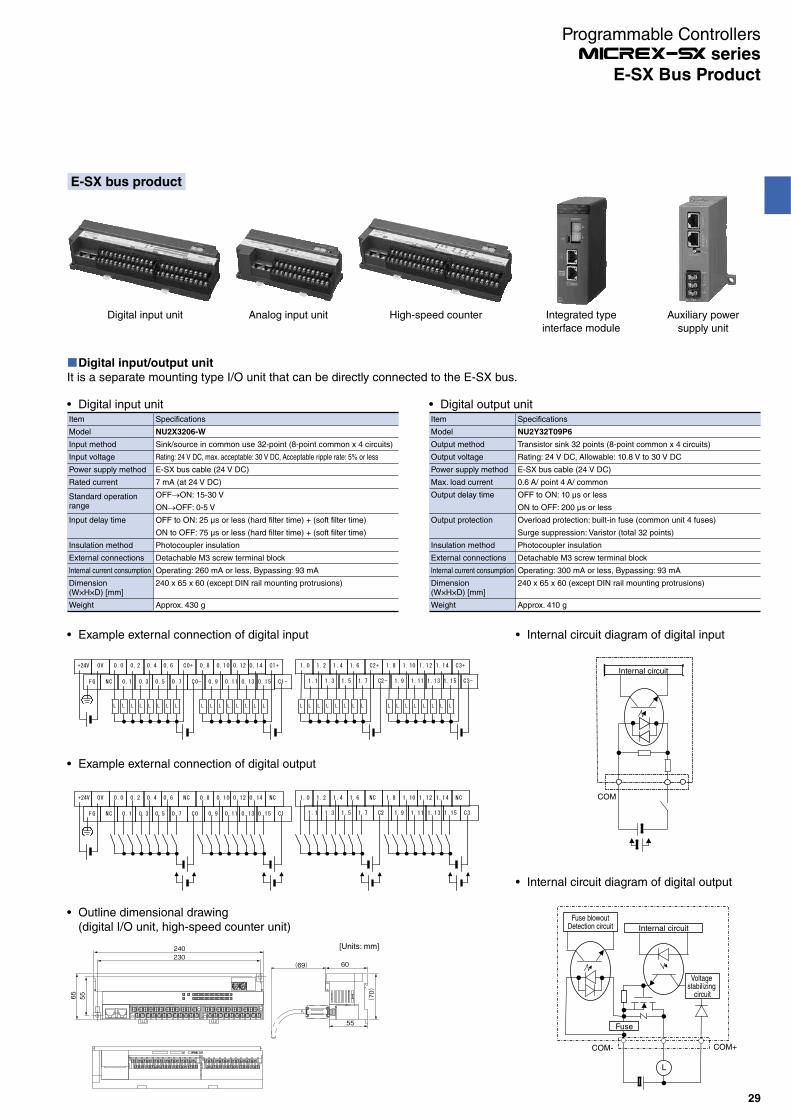
Digital input/output unit
It is a separate mounting type I/O unit that can be directly connected to the E-SX bus.
Internal circuit
COM
Fuse blowoutDetection circuit Internal circuit
Voltage stabilizing
circuit
Fuse
COM- COM+
L
0V+24V 0.0 0.2 0.4 0.6 NC 0.8 0.10 0.12 0.14 NC
FG NC 0.1 0.3 0.5 0.7 C0 0.9 0.11 0.13 0.15 C1
1.0 1.2 1.4 1.6 NC 1.8 1.10 1.12 1.14 NC
1.1 1.3 1.5 1.7 C2 1.9 1.11 1.13 1.15 C3
FG NC 0.1 0.3 0.5 0.7 C0- 0.9 0.11 0.13 0.15 C1- 1.1 1.3 1.5 1.7 C2- 1.9 1.11 1.13 1.15 C3-
L L L L L L L L L L L L L L L L L L L L L L L L L L L L L L L L
0V+24V 0.0 0.2 0.4 0.6 C0+ 0.8 0.10 0.12 0.14 C1+ 1.0 1.2 1.4 1.6 C2+ 1.8 1.10 1.12 1.14 C3+
Internal circuit diagram of digital inputExample external connection of digital input
Internal circuit diagram of digital output
Example external connection of digital output
Digital input unitItem Specifications
Model NU2X3206-W
Input method Sink/source in common use 32-point (8-point common x 4 circuits)
Input voltage Rating: 24 V DC, max. acceptable: 30 V DC, Acceptable ripple rate: 5% or less
Power supply method E-SX bus cable (24 V DC)
Rated current 7 mA (at 24 V DC)
Standard operation range
OFF ON: 15-30 V
ON OFF: 0-5 V
Input delay time OFF to ON: 25 µs or less (hard filter time) + (soft filter time)
ON to OFF: 75 µs or less (hard filter time) + (soft filter time)
Insulation method Photocoupler insulation
External connections Detachable M3 screw terminal block
Internal current consumption Operating: 260 mA or less, Bypassing: 93 mA
Dimension(W×H×D) [mm]
240 x 65 x 60 (except DIN rail mounting protrusions)
Weight Approx. 430 g
Digital output unitItem Specifications
Model NU2Y32T09P6
Output method Transistor sink 32 points (8-point common x 4 circuits)
Output voltage Rating: 24 V DC, Allowable: 10.8 V to 30 V DC
Power supply method E-SX bus cable (24 V DC)
Max. load current 0.6 A/ point 4 A/ common
Output delay time OFF to ON: 10 µs or less
ON to OFF: 200 µs or less
Output protection Overload protection: built-in fuse (common unit 4 fuses)
Surge suppression: Varistor (total 32 points)
Insulation method Photocoupler insulation
External connections Detachable M3 screw terminal block
Internal current consumption Operating: 300 mA or less, Bypassing: 93 mA
Dimension(W×H×D) [mm]
240 x 65 x 60 (except DIN rail mounting protrusions)
Weight Approx. 410 g
[Units: mm]240
60
55
65
230
55
(70
)
(69)
Outline dimensional drawing (digital I/O unit, high-speed counter unit)
E-SX bus product
Digital input unit Analog input unit High-speed counter Integrated type
interface module
Auxiliary power
supply unit
29
E-SX Bus Product
Programmable Controllers series
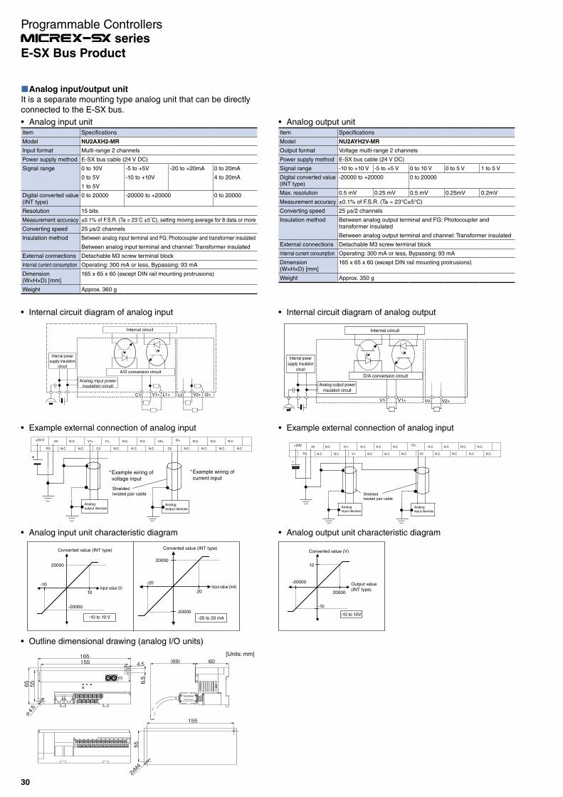
Analog input/output unit
It is a separate mounting type analog unit that can be directly connected to the E-SX bus.
Analog input unitItem Specifications
Model NU2AXH2-MR
Input format Multi-range 2 channels
Power supply method E-SX bus cable (24 V DC)
Signal range 0 to 10V -5 to +5V -20 to +20mA 0 to 20mA
0 to 5V -10 to +10V 4 to 20mA
1 to 5V
Digital converted value(INT type)
0 to 20000 -20000 to +20000 0 to 20000
Resolution 15 bits
Measurement accuracy ±0.1% of F.S.R. (Ta = 23˚C ±5˚C), setting moving average for 8 data or more
Converting speed 25 μs/2 channels
Insulation method Between analog input terminal and FG: Photocoupler and transformer insulated
Between analog input terminal and channel: Transformer insulated
External connections Detachable M3 screw terminal block
Internal current consumption Operating: 300 mA or less, Bypassing: 93 mA
Dimension(W×H×D) [mm]
165 x 65 x 60 (except DIN rail mounting protrusions)
Weight Approx. 360 g
Analog output unitItem Specifications
Model NU2AYH2V-MR
Output format Voltage multi-range 2 channels
Power supply method E-SX bus cable (24 V DC)
Signal range -10 to +10 V -5 to +5 V 0 to 10 V 0 to 5 V 1 to 5 V
Digital converted value(INT type)
-20000 to +20000 0 to 20000
Max. resolution 0.5 mV 0.25 mV 0.5 mV 0.25mV 0.2mV
Measurement accuracy ±0.1% of F.S.R. (Ta = 23°C±5°C)
Converting speed 25 μs/2 channels
Insulation method Between analog output terminal and FG: Photocoupler and transformer insulated
Between analog output terminal and channel: Transformer insulated
External connections Detachable M3 screw terminal block
Internal current consumption Operating: 300 mA or less, Bypassing: 93 mA
Dimension(W×H×D) [mm]
165 x 65 x 60 (except DIN rail mounting protrusions)
Weight Approx. 350 g
D/A conversion circuit
Analog output powerinsulation circuit
V1- V1+ V2- V2+
Internal circuit
Internal powersupply insulation
circuit
Internal circuit diagram of analog output
+24V 0V N.C
N.CN.C
V1+
V1
N.C N.C N.C
N.C N.C N.C
N.C N.C N.C N.C
N.CN.CN.CN.C
V2+
FG V2
+
Analoginput devices
Analoginput devices
Shieldedtwisted pair cable
Example external connection of analog input
Analog output unit characteristic diagram
-10
10
Converted value (V)
Output value(INT type)
-10 to 10V
20000
-20000
+
*Example wiring ofvoltage input
*Example wiring ofcurrent input
+24 V 0V N.C. V1+ I1+ N.C. N.C. V2+ I2+ N.C. N.C. N.C.
FG N.C. N.C. C2 N.C. N.C. N.C. C2 N.C. N.C. N.C. N.C
Shieldedtwisted pair cable
Analogoutput devices
Analogoutput devices
Example external connection of analog input
Internal circuit diagram of analog input
Internal circuit
Internal powersupply insulation
circuit
Analog input powerinsulation circuit
A/D conversion circuit
C1- V1+ L1+ C2- V2+ I2+
[Units: mm]
(69)
55
2xM4
155
65∅4.5
55
155165
4.5
6.5
60
Outline dimensional drawing (analog I/O units)
Analog input unit characteristic diagram
-20000
-10 to 10 V
Input value (V)
Converted value (INT type)
20000
Input value (V) 10
-10Input value (V)Input value (mA)
Converted value (INT type)
20000
20Input value (mA)
-20
-20000
-20 to 20 mA
30
E-SX Bus Product
Programmable Controllers series
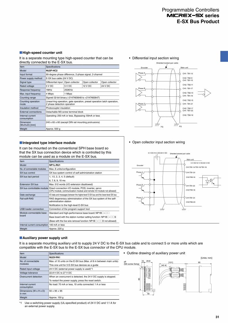
Item Specifications
Model NU2F-HC2
Input format 90-degree phase difference, 2-phase signal, 2-channel
Power supply method E-SX bus cable (24 V DC)
Signal type Differential input Open collector Open collector Open collector
Rated voltage 5 V DC 5 V DC 12 V DC 24 V DC
Response frequency 1MHz 250KHz
Max. input frequency 4 Mbps 1 Mbps
Counting range Signed 32-bit binary (-2147483648 to +2147483647)
Counting operation mode
Linear/ring operation, gate operation, preset operation latch operation, Z phase detection operation
Insulation method Photocoupler insulation
External connections Detachable M3 screw terminal block
Internal current consumption
Operating: 250 mA or less, Bypassing: 93mA or less
Dimension(W×H×D) [mm]
240 x 65 x 60 (except DIN rail mounting protrusions)
Weight Approx. 500 g
High-speed counter unit
Item Specifications
Model NP1L-RU1
No. of connectable modules Max. 8 units/configuration
SX bus control SX bus system control of self-administration station
SX bus tact period 1, 1.5, 2, 3, 4, 5 (default)
6, 7, 8, 9, 10 ms
Extension SX bus Max. 512 words (I/O extension disallowed)
SX bus controllable module Direct connection I/O module, POD, inverter, servo(CPU module, communication module and remote I/O module not allowed)
Date exchange I/O data and messages between the higher-level E-SX bus and the lower-level SX bus
Fail-soft-RAS RAS degeneracy administration of the SX bus system of the self-administration station
Notification to the high-level E-SX bus
USB loader connection Connection of the program support tool
Module-connectable base board
Standard and high-performance base board: NP1B-
Base board with the station number setting function: NP1B-S
(Base with the live wire removal function: NP1B-D not allowed)
Internal current consumption 140 mA or less
Weight Approx. 220 g
It can be mounted on the conventional SPH base board so that the SX bus connection device which is controlled by this module can be used as a module on the E-SX bus.
Integrated type interface module
Auxiliary power supply unit
Item Specifications
Model NU2V-PA1
No. of connectable modules
Max. of 10 units on the E-SX bus (Max. of 8 m between main units)
This one unit for 5 E-SX bus devices as a guide
Rated input voltage 24 V DC (external power supply is used)*1
Voltage tolerance 22.8 V DC to 27 V DC
Overcurrent detection When an overcurrent is detected, the 24 V DC supply is stopped.
To restart the power supply, press the reset switch.
Internal current consumption
No load: 70 mA or less, 10 units connected: 1 A or less
Dimensions (W x H x D) in mm
50 × 95 × 95
Weight Approx. 150 g
*1 Use a switching power supply (UL-specified product) of 24 V DC and 1.1 A for an external power supply.
It is a separate mounting auxiliary unit to supply 24 V DC to the E-SX bus cable and to connect 5 or more units which are compatible with the E-SX bus to the E-SX bus connector of the CPU module.
5 V DC/12 V DC/24 V DC
CH1:TB1-14/TB1-16/TB1-18
Phase A
Phase Z
Phase BCH1:TB1-22
CH2:TB2-18
CH1:TB1-20
CH2:TB2-16
CH1:TB1-24
CH2:TB2-20
5 V DC/12 V DC/24 V DC
FGFG
Main unit
Encoder
Shielded twisted pair cable
Shielded twisted pair cable
Main unitEncoder
Phase A
Phase Z
Phase B
FG
CH1: TB1-13
CH2: TB2-9
CH1: TB1-15
CH2: TB2-11
CH1: TB1-17
CH2: TB2-13
CH1: TB1-19
CH2: TB2-15
CH1: TB1-21
CH2: TB2-17
CH1: TB1-23
CH2: TB2-19
FG
It is a separate mounting type high-speed counter that can be directly connected to the E-SX bus.
Outline drawing of auxiliary power unit
[Units: mm]
85
40
106(M4 screw fixing)
29.8[101] 95
[42.4]
Differential input section wiring
Open collector input section wiring
31
E-SX Bus Product
Programmable Controllers series
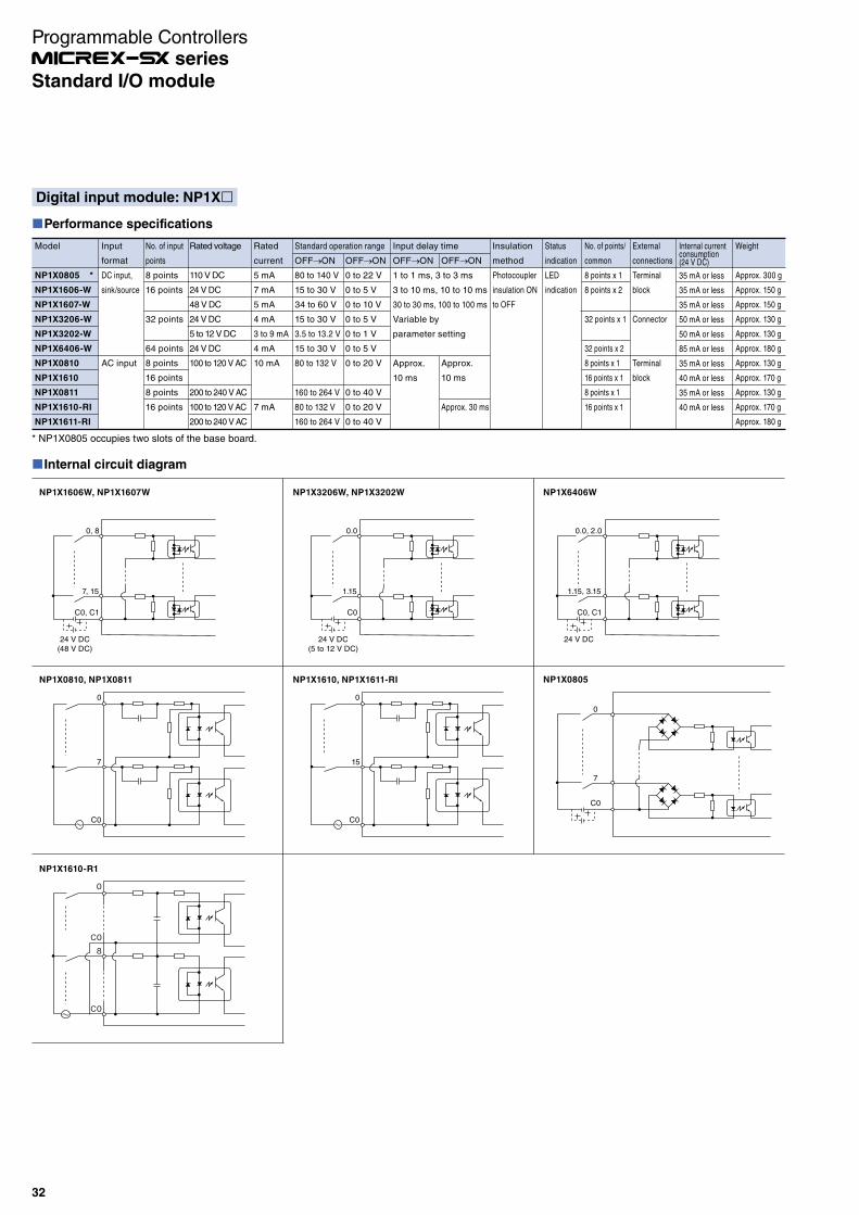
Digital input module: NP1X
Performance specifications
Model
NP1X0805 *
NP1X1606-W
NP1X1607-W
NP1X3206-W
NP1X3202-W
NP1X6406-W
NP1X0810
NP1X1610
NP1X0811
NP1X1610-RI
NP1X1611-RI
Input
format
DC input,
sink/source
AC input
No. of input
points
8 points
16 points
32 points
64 points
8 points
16 points
8 points
16 points
Rated voltage
110 V DC
24 V DC
48 V DC
24 V DC
5 to 12 V DC
24 V DC
100 to 120 V AC
200 to 240 V AC
100 to 120 V AC
200 to 240 V AC
Rated
current
5 mA
7 mA
5 mA
4 mA
3 to 9 mA
4 mA
10 mA
7 mA
Standard operation range
OFF ON
80 to 140 V
15 to 30 V
34 to 60 V
15 to 30 V
3.5 to 13.2 V
15 to 30 V
80 to 132 V
160 to 264 V
80 to 132 V
160 to 264 V
OFF ON
0 to 22 V
0 to 5 V
0 to 10 V
0 to 5 V
0 to 1 V
0 to 5 V
0 to 20 V
0 to 40 V
0 to 20 V
0 to 40 V
Input delay time
OFF ON
1 to 1 ms, 3 to 3 ms
3 to 10 ms, 10 to 10 ms
30 to 30 ms, 100 to 100 ms
Variable by
parameter setting
Approx.
10 ms
OFF ON
Approx.
10 ms
Approx. 30 ms
Insulation
method
Photocoupler
insulation ON
to OFF
Status
indication
LED
indication
No. of points/
common
8 points x 1
8 points x 2
32 points x 1
32 points x 2
8 points x 1
16 points x 1
8 points x 1
16 points x 1
External
connections
Terminal
block
Connector
Terminal
block
Internal currentconsumption(24 V DC)
35 mA or less
35 mA or less
35 mA or less
50 mA or less
50 mA or less
85 mA or less
35 mA or less
40 mA or less
35 mA or less
40 mA or less
Weight
Approx. 300 g
Approx. 150 g
Approx. 150 g
Approx. 130 g
Approx. 130 g
Approx. 180 g
Approx. 130 g
Approx. 170 g
Approx. 130 g
Approx. 170 g
Approx. 180 g
* NP1X0805 occupies two slots of the base board.
Internal circuit diagram
C0
C0
0
8
NP1X1610-R1
24 V DC(48 V DC)
C0, C1
C0
7, 15
0
7
0, 8
C0
0
15
24 V DC(5 to 12 V DC)
C0
1.15
0.0
24 V DC
C0, C1
1.15, 3.15
0.0, 2.0
C0
7
0
NP1X1606W, NP1X1607W NP1X3206W, NP1X3202W NP1X6406W
NP1X0805NP1X0810, NP1X0811 NP1X1610, NP1X1611-RI
32
Standard I/O module
Programmable Controllers series

Internal circuit diagram
7
0
P
M
Fuse
7,15
0,8
P0,P1
M0,M1
Fuse
7
0
P
M
Fuse
0,4
3,7
CO,C1
0
C0
7
C7
AVR
AVRAVR
Fuse
0,8
7,15
P0,P1
M0,M1
AVR
Fuse
P0
0.0
1.15
M0
0
7
C0
8
15
C1
AVRFuse
0.0
1.15
P0
M0AVR Fuse
0.0 , 2.0
1.15 , 3.15
P0 , P1
M0 , M1AVR
NP1Y08T0902 NP1Y16T09P6 , NP1Y16T10P2 NP1Y32T09P1
NP1Y08U0902 NP1Y16U09P6 NP1Y32U09P1 NP1Y64U09P1
NP1Y08S NP1Y08R-04 NP1Y16R-08
L
L
L
L
L
L
R
R
L
L
L
LL
L
L
L
L
L
L
L
R
L
R
R
L
R
L
L
M0 , M1
0.0 , 2.0
P0 , P1
1.15 , 3.15
AVR
Fuse
NP1Y64T09P1
L
L
0
C0
NP1Y08R-00
L
R
7
C7
L
R
Digital output module: NP1Y
Performance specifications
Model
NP1Y08T0902
NP1Y16T09P6
NP1Y16T10P2
NP1Y32T09P1
NP1Y64T09P1
NP1Y08U0902
NP1Y16U09P6
NP1Y32U09P1
NP1Y64U09P1
NP1Y08S
NP1Y08R-04
NP1Y16R-08
NP1Y08R-00
Output
format
Transistor
output sink
type
Transistor
output source
type
SSR output
Relay output
No. of
output points
8 points
16 points
32 points
64 points
8 points
16 points
32 points
64 points
8 points
8 points
16 points
8 points
Rated
voltage
12 to
24 V DC
48 V DC
12 to
24 V DC
100 to
240 V AC
110 V DC/
240 V AC
External
connections
Terminal block
Connector
Terminal block
Connector
Terminal block
Max. load current
1 point
2.4 A
0.6 A
0.2 A
0.12A
2.4 A
0.6 A
0.12 A
2.2 A
30 V DC/
264 V AC:
2.2 A
110 V DC:
0.2 A
Common
8 A
4 A
1.6 A
3.2 A
8 A
4 A
3.2 A
2.2 A
30 V DC/
264 V AC:
4 A
110 V DC:
0.8 A
30 V DC/
264 V AC:
8 A
110 V DC:
1.6 A
—
Output delay time
OFF ON
1 ms or less
10 ms or less
Approx. 10 ms
ON OFF
1 ms or less
10 ms or less
Approx. 10 ms
Insulation
method
Photocoupler
insulation
Relay
insulation
Status
indication
LED
indication
No. of points/
common
8 points x 1
8 points x 2
32 points x 1
32 points x 2
8 points x 1
8 points x 2
32 points x 1
32 points x 2
All points are
independent.
4 points x 2
8 points x 2
All points are
independent.
Surge
protection
Varistor
Zener diode
Varistor
Diode
CR absorber
and varistor
Varistor
Internal current
consumption (24 V DC)
20 mA or less
42 mA or less
42 mA or less
45 mA or less
90 mA or less
20 mA or less
30 mA or less
45 mA or less
90 mA or less
80 mA or less
80 mA or less
176 mA or less
100 mA or less
Weight
Approx. 150 g
Approx. 160 g
Approx. 160 g
Approx. 130 g
Approx. 180 g
Approx. 150 g
Approx. 160 g
Approx. 140 g
Approx. 180 g
Approx. 200 g
Approx. 150 g
Approx. 190 g
Approx. 170 g
33
Standard I/O module
Programmable Controllers series

Digital I/O module: NP1W
Performance specifications
Model
NP1W1606T
NP1W3206T
NP1W1606U
NP1W3206U
NP1W6406T
NP1W6406U
Input
Input format
DC input,
source
DC input,
sink
DC bidirectional
input
DC bidirectional
input
No. of input points
8 point
16 point
8 point
16 point
32 point
32 point
Rated
voltage
24 V DC
Rated
current
7 mA
4 mA
7 mA
4 mA
4 mA
4 mA
No. of points/
common
8 points x 1
16 points x 1
8 points x 1
16 points
32 points x 1
32 points x 1
Output
Output
format
Transistor
output sink
Transistor
output source
Transistor
output sink
Transistor
output source
No. of output points
8 point
16 point
8 point
16 point
32 point
32 point
Rated
voltage
12 to
24 V DC
Max. load current
1 point
0.6 A/point
0.12 A/point
0.6A/point
0.12 A/point
0.12 A/point
0.12 A/point
Common
4 A/common
1.6 A/common
4 A/common
1.6 A/common
3.2 A/common
3.2 A/common
No. of points/
common
8 points x 1
16 points x 1
8 points x 1
16 points x 1
32 points x 1
32 points x 1
Common
Insulation
method
Photocoupler
insulation
Status
indication
LED
indication
External
connections
Terminal block
Connector
Terminal block
Connector
Connector
Connector
Internal current
consumption (24 V DC)
35 mA or less
50 mA or less
35 mA or less
50 mA or less
90 mA or less
90 mA or less
Weight
Approx. 150 g
Approx. 140 g
Approx. 150 g
Approx. 140 g
Approx. 180 g
Approx. 180 g
Internal circuit diagram
AVR
Fuse
Fuse
8 (1.0)
15 (1.7)
0 (0.0)
7 (0.7)
C0
Output circuitInput circuit
AVR
FuseP0
M0
8 (1.0)
0 (0.0)
7 (0.7)
C0
15 (1.7)
Output circuitInput circuit
P0
M0
AVR Fuse
1.0
1.15
Output circuitInput circuit
P0
M0
P0
1.0
1.15
M0
0.15
C0
0.0
0.15
C0
0.0
Output circuitInput circuit
NP1W1606T NP1W1606U
NP1W3206T NP1W3206U
L
L
L
L
L
L
AVR Fuse
1.0
3.15
Output circuit
P0
M0
L
L
L
L
Fuse
P1
2.0
3.15
M1
1.15
C0
0.0
24 V DC
Output circuitInput circuit
1.15
C0
0.0
24 V DC
Input circuit
NP1W6406T NP1W6406U
L
L
AVR
AVR
34
Standard I/O module
Programmable Controllers series

Pulse train output built-in digital output module: NP1Y32T09P1-A
Module with transistor output and pulse train output built-inPulse train output (20 kHz) can be selected up to max. 4 ch x 2 phases
Built-in pulse train output specifications
Item
No. of pulse train
output channels
Max. output frequency
Pulse output mode
Output pulse counting method
Operation mode
No. of general-purpose
output points
Specifications
4 channels (max.) x 2 phases
(Only with the pulse train output mode selected)
20 kHz
(1) Forward pulse, reverse pulse
(2) Pulse train + sign
Built-in 16-bit up-down counter
Start, stop, clear
Ring operation
Frequency/rotation direction/output form setting
32 points (min. 24 points in pulse train output mode)
Internal circuit diagram
L
L
AVR
Fuse
P0
12.0
13.15
M0
NP1Y32T09P1-A
High-speed digital input module: NP1X3206-A
· Digital input module with pulse catch input· Pulse catch input of min. 20 µs or normal input· Pulse counter input function of max. 20 kHz, 4 ch (2-phase)
Internal circuit diagram
2.15
1.0
C0DC24V
NP1X3206-A
Specifications
Model
NP1X3206-A
Input
format
24V DC
source type
No. of
input points
32 points
Rated
voltage
24 V DC
Rated
current
4 mA
Standard operation range
OFF ON
15 to 30 V
ON OFF
0 to 5 V
ON OFF
Input delay time
OFF ON
0 to 100 ms
Variable by parameter
setting
Insulation
method
Photocoupler
insulation
Status
indication
LED
indication
No. of points/
common
32 points x 1
External
connections
Connector
Internal current
consumption (24 V DC)
50 mA or less
Weight
Approx. 130 g
Specifications
Model
NP1Y32T09P1-A
Output
format
Transistor
output
sink type
No. of
output points
32 point
Rated
voltage
12 to
24 V DC
External
connections
Connector
Max. load current
1 point
0.12A
Common
3.2 A
Output delay time
OFF ON
Port 1 to 8: 20 µs or less
Port 9 to 32: 1 ms or less
ON OFF
Insulation
method
Photocoupler
insulation
Status
indication
LED
indication
No. of points/
common
32 points x 1
Surge
protection
Zener diode
Internal current
consumption (24 V DC)
50 mA or less
Weight
Approx. 200 g
35
Standard I/O module
Programmable Controllers series
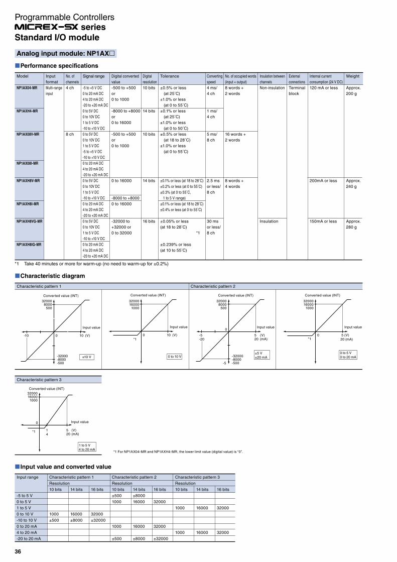
Characteristic diagram
Characteristic pattern 3
Characteristic pattern 1 Characteristic pattern 2
Converted value (INT)
320008000
500
-32000-8000-500
Input value
±10 V
0 5 10-10 (V)
Converted value (INT)
3200016000
1000
Input value
0 to 10 V
0 10 (V)
Converted value (INT)
320008000
500
-32000-8000-500
Input value0
5-5
-5
-20(V)
20 (mA)
±5 V±20 mA
Converted value (INT)
3200016000
1000
Input value
0 5 (V)20 (mA)
0 to 5 V0 to 20 mA
Converted value (INT)
3200016000
1000
Input value0
14
5 (V)20 (mA)
1 to 5 V4 to 20 mA
*1 *1
*1
*1 For NP1AX04-MR and NP1AXH4-MR, the lower limit value (digital value) is “0”.
Input value and converted value
Input range
-5 to 5 V
0 to 5 V
1 to 5 V
0 to 10 V
-10 to 10 V
0 to 20 mA
4 to 20 mA
-20 to 20 mA
Characteristic pattern 1
Resolution
10 bits
1000
±500
14 bits
16000
±8000
16 bits
32000
±32000
Characteristic pattern 3
Resolution
10 bits
1000
1000
14 bits
16000
16000
16 bits
32000
32000
Characteristic pattern 2
Resolution
10 bits
±500
1000
1000
±500
14 bits
±8000
16000
16000
±8000
16 bits
32000
32000
±32000
Analog input module: NP1AX
Performance specifications
Model
NP1AX04-MR
NP1AXH4-MR
NP1AX08V-MR
NP1AX08I-MR
NP1AXH8V-MR
NP1AXH8I-MR
NP1AXH8VG-MR
NP1AXH8IG-MR
Input
format
Multi-range
input
No. of
channels
4 ch
8 ch
Signal range
-5 to +5 V DC
0 to 20 mA DC
4 to 20 mA DC
-20 to +20 mA DC
0 to 5V DC
0 to 10V DC
1 to 5 V DC
-10 to +10 V DC
0 to 5V DC
0 to 10V DC
1 to 5 V DC
-5 to +5 V DC
-10 to +10 V DC
0 to 20 mA DC
4 to 20 mA DC
-20 to +20 mA DC
0 to 5V DC
0 to 10V DC
1 to 5 V DC
-10 to +10 V DC
0 to 20 mA DC
4 to 20 mA DC
-20 to +20 mA DC
0 to 5V DC
0 to 10V DC
1 to 5 V DC
-10 to +10 V DC
0 to 20 mA DC
4 to 20 mA DC
-20 to +20 mA DC
Digital converted
value
-500 to +500
or
0 to 1000
-8000 to +8000
or
0 to 16000
-500 to +500
or
0 to 1000
0 to 16000
-8000 to +8000
0 to 16000
-32000 to
+32000 or
0 to 32000
Digital
resolution
10 bits
14 bits
10 bits
14 bits
16 bits
Tolerance
±0.5% or less
(at 25˚C)
±1.0% or less
(at 0 to 55˚C)
±0.1% or less
(at 25˚C)
±1.0% or less
(at 0 to 50˚C)
±0.5% or less
(at 18 to 28˚C)
±1.0% or less
(at 0 to 55˚C)
±0.1% or less (at 18 to 28˚C)
±0.2% or less (at 0 to 55˚C)
±0.3% (at 0 to 55˚C,
1 to 5 V range)
±0.1% or less (at 18 to 28˚C)
±0.4% or less (at 0 to 55˚C)
±0.05% or less
(at 18 to 28˚C)
*1
±0.239% or less
(at 10 to 55˚C)
Converting
speed
4 ms/
4 ch
1 ms/
4 ch
5 ms/
8 ch
2.5 ms
or less/
8 ch
30 ms
or less/
8 ch
No. of occupied words
(input + output)
8 words +
2 words
16 words +
2 words
8 words +
4 words
Insulation between
channels
Non-insulation
Insulation
External
connections
Terminal
block
Internal current
consumption (24 V DC)
120 mA or less
200mA or less
150mA or less
Weight
Approx.
200 g
Approx.
240 g
Approx.
280 g
*1 Take 40 minutes or more for warm-up (no need to warm-up for ±0.2%)
36
Standard I/O module
Programmable Controllers series

Characteristic diagram
Characteristic pattern 2
Characteristic pattern 1 Characteristic pattern 2
Converted value (V)
10
-10
Input value
±10 V
0
0
8000500
-8000-500
(INT)
Converted value (V)
10
Input value
0 to 10 V
0 160001000
(INT)
Converted value (V)
5
-5
Input value0
8000500
-8000-500
(INT)
±5 V
Converted value (V)
5
Input value
0 to 5 V
0 160001000
(INT)
Converted value (V/mA)
20
4
5
1 Input value
0 160001000
(INT)
1 to 5 V4 to 20 mA
Converted value (mA)
20
Input value
0 to 20 mA
160001000
(INT)
Characteristic pattern 3
*1
*1 For NP1AY02-MR and NP1AYH2-MR, the lower limit value (digital value) is “0”.
*1 *1
Output value and converted value
Output range
-5 to 5 V
0 to 5 V
1 to 5 V
0 to 10 V
-10 to 10 V
0 to 20 mA
4 to 20 mA
Characteristic pattern 1
Resolution
10 bits
1000
±500
14 bits
16000
±8000
15 bits
16000
±16000
Characteristic pattern 3
Resolution
10 bits
1000
1000
14 bits
16000
16000
15 bits
16000
16000
Characteristic pattern 2
Resolution
10 bits
±500
1000
1000
14 bits
±8000
16000
16000
15 bits
16000
16000
Analog output module: NP1AY
Performance specifications
*1
*1
Model
NP1AY02-MR
NP1AYH2-MR
NP1AYH4V-MR
NP1AYH4I-MR
NP1AYH4VG-MR
NP1AYH4IG-MR
NP1AYH8V-MR
NP1AYH8I-MR
Output
format
Multi-range
output
No. of
channels
2
4
8
Signal
range
-5 to +5 V DC
0 to 20 mA DC
4 to 20 mA DC
0 to 5 V DC
0 to 10 V DC
1 to 5 V DC
-10 to +10 V DC
0 to 5V DC
0 to 10 V DC
1 to 5 V DC
-10 to +10 V DC
0 to 20 mA DC
4 to 20 mA DC
0 to 5V DC
0 to 10V DC
1 to 5 V DC
-10 to +10 V DC
0 to 20 mA DC
4 to 20 mA DC
0 to 5V DC
0 to 10V DC
1 to 5 V DC
-10 to +10 V DC
0 to 20 mA DC
4 to 20 mA DC
Digital
converted value
-500 to +500
or 0 to 1000
-8000 to +8000
or 0 to 16000
-8000 to +8000
or 0 to 16000
0 to 16000
-16000 to +16000
or 0 to 16000
0 to 16000
-8000 to +8000
or 0 to 16000
0 to 16000
Digital
resolution
10 bits
14 bits
Tolerance
±0.5% or less (at 25˚C)
±1.0% or less
(at 0 to 55˚C)
±0.1% or less (at 25˚C)
±1.0% or less
(at 0 to 50˚C)
±0.1% or less (at 18 to 28˚C)
±0.2% or less (at 0 to 55˚C)
±0.3%
(at 0 to 55˚C, 1 to 5 V range)
±0.1% or less (at 18 to 28˚C)
±0.4% or less (at 0 to 55˚C)
±0.1% or less (at 18 to 28˚C)
±0.289% or less
(at 0 to 55˚C)
±0.1% or less (at 18 to 28˚C)
±0.289% or less (at 0 to 55˚C)
±0.1% or less (at 18 to 28˚C)
±0.2% or less (at 0 to 55˚C)
±0.3%
(at 0 to 55˚C, 1 to 5 V range)
±0.1% or less (at 18 to 28˚C)
±0.4% or less (at 0 to 55˚C)
Converting
speed
2 ms/
2 ch
1 ms/
2 ch
1 ms/
4 ch
0.6 ms/
4 ch
2 ms/
8 ch
No. of occupied words
(input + output)
2 words + 4 words
4 words + 4 words
4 words + +8 words
External
connections
Terminal block
Insulation
between channels
Non-insulation
Insulation
Non-insulation
Internal current
consumption (24 V DC)
120 mA or less
200 mA or less
250 mA or less
240 mA or less
300 mA or less
Weight
Approx. 200 g
Approx. 240 g
Approx. 300 g
Approx. 240 g
*1 Take 30 minutes or more for warm-up (no need to warm-up for ±0.2%)
37
Standard I/O module
Programmable Controllers series

Analog Input/Output module: NP1AWH6-MR
Performance specifications
Model
NP1AWH6-MR
I/O form
Multi-range
I/O
No. of
channels
4
2
Signal range
Voltage input:
0 to 5 V DC
0 to 10 V DC
1 to 5 V DC
-10 to +10 V DC
Current input:
0 to 20 mA DC
4 to 20 mA DC
-20 to +20 mA DC
Voltage output:
0 to 5 V DC
0 to 10 V DC
1 to 5 V DC
-10 to +10 V DC
Current output:
0 to 20 mA DC
4 to 20 mA DC
Digital converted
value
-8000 to +8000 or
0 to 16000
Digital
resolution
14 bits
Tolerance
±0.1% or less
(at 18 to 28˚C)
±0.2% or less
(at 0 to 55˚C)
±0.3%
(0 to 55˚C, 0 to 20 mA/
4 to 20 mA ranges)
Converting
speed
1 ms/
4 ch
0.5 ms/
2 ch
No. of occupied words
(Input + output)
4 words + 4 words
External
connections
Terminal block
Insulation
between channels
Non-insulation
Internal current
consumption (24 V DC)
200 mA or less
Weight
Approx. 240 g
Characteristic diagram
Analog input
Characteristic pattern 1 Characteristic pattern 2 Characteristic pattern 3
Converted value (INT)
8000
-8000
Input value
0 10-10-20
(V)20 (mA)
Converted value (INT)
16000
Input value
0 to 10 V
0 10 (V)
Converted value (INT)
16000
Input value
0 5 (V)20 (mA)
0 to 5 V0 to 20 mA
Converted value (INT)
16000
Input value0
14
5 (V)20 (mA)
1 to 5 V4 to 20 mA
±10 V±20 mA
Analog output
Characteristic pattern 1 Characteristic pattern 2
Converted value (V/mA)
10
-10
Input value
0 8000-8000 (INT)
Converted value (V)
10
Input value
0 to 10 V±10 V
0 16000 (INT)
Converted value (V)
5
Input value
0 to 5 V
0 16000 (INT)
Converted value (V/mA)
20
4
5
1 Input value
0 16000(INT)
1 to 5 V4 to 20 mA
Converted value (mA)
20
Input value
0 to 20 mA
16000 (INT)
Characteristic pattern 3
Input/output value and converted value
Analog input
Input range
0 to 5 V
1 to 5 V
0 to 10 V
-10 to 10 V
0 to 20 mA
4 to 20 mA
-20 to 20 mA
Characteristic pattern 1
16000
±8000
±8000
Characteristic pattern 2
16000
16000
Characteristic pattern 3
16000
16000
Analog output
Output range
0 to 5 V
1 to 5 V
0 to 10 V
-10 to 10 V
0 to 20 mA
4 to 20 mA
Characteristic pattern 1
16000
±8000
Characteristic pattern 2
16000
16000
Characteristic pattern 3
16000
16000
38
Standard I/O module
Programmable Controllers series

Resistance thermometer element input module: NP1AX -PT
IEC Standards conformed sensors (platinum resistance thermometer bulb) can be connected. (Batch setting is possible for all channels.)Error detection (resistance thermometer element wire breakage detection, resistance thermometer element shunt detection, etc.) is possible.Temperature scale is selectable between Celsius and Fahrenheit.The NP1AXH6G-PT provides high accuracy and high resolution, thereby enabling fine-grained measurements.
Characteristic diagram
(Unit of 0.1˚C) (Unit of 1˚C) Converted value
4000 (400)
Input value (˚C)
400
-20
-200 (-20)
(Unit of 0.1˚C) (Unit of 1˚C) Converted value
4000 (400)
Input value (˚C)
400
-40.0
-400 (-40)
Type of resistance thermometer element and resolutions
NP1AXH4-PT
Type of resistance
thermometer element
PT
JPt
Celsius (˚C)
Input range
0 to 200
-20 to 80
0 to 100
0 to 400
-200 to 200
-200 to 600
0.0 to 200.0
-20.0 to 80.0
0.0 to 100.0
0.0 to 400.0
-200.0 to 200.0
-200.0 to 600.0
0 to 200
-20 to 80
0 to 100
0 to 400
-200 to 200
-200 to 500
0.0 to 200.0
-20.0 to 80.0
0.0 to 100.0
0.0 to 400.0
-200.0 to 200.0
-200.0 to 500.0
Fahrenheit (˚F)
Input range
32 to 392
-4 to 176
32 to 212
32 to 752
-328 to 392
-328 to 1112
32.0 to 392.0
-4.0 to 176.0
32.0 to 212.0
32.0 to 752.0
-328.0 to 392.0
-328.0 to 1112.0
32 to 392
-4 to 176
32 to 212
32 to 752
-328 to 392
-328 to 932
32.0 to 392.0
-4.0 to 176.0
32.0 to 212.0
32.0 to 752.0
-328.0 to 392.0
-328.0 to 932.0
Resolution
of data
1
0.1
1
0.1
Note: The measuring range of temperature is ±5% of the input range span.
NP1AXH6G-PT
Platinum resistance thermometer element
Type
PT
JPt
Celsius (˚C)
Input range
0 to 200
-20 to 80
0 to 100
0 to 400
-200 to 200
-200 to 600
-200 to 850
0.0 to 200.0
-20.0 to 80.0
0.0 to 100.0
0.0 to 400.0
-200.0 to 200.0
-200.0 to 600.0
-200.0 to 850.0
-20.00 to 80.00
0 to 200
-20 to 80
0 to 100
0 to 400
-200 to 200
-200 to 500
0.0 to 200.0
-20.0 to 80.0
0.0 to 100.0
0.0 to 400.0
-200.0 to 200.0
-200.0 to 500.0
Fahrenheit (˚F)
Input range
32 to 392
-4 to 176
32 to 212
32 to 752
-328 to 392
-328 to 1112
-328 to 1562
32.0 to 392.0
-4.0 to 176.0
32.0 to 212.0
32.0 to 752.0
-328.0 to 392.0
-328.0 to 1112.0
-328.0 to 1562.0
-4.00 to 176.00
32 to 392
-4 to 176
32 to 212
32 to 752
-328 to 392
-328 to 932
32.0 to 392.0
-4.0 to 176.0
32.0 to 212.0
32.0 to 752.0
-328.0 to 392.0
-328.0 to 932.0
Resolution
of data
1
0.1
0.01
1
0.1
Specifications
Item
Model
Measurement accuracy *2
Allowable input wiring resistance
Sampling interval
Input filtering time
No. of input channels
No. of occupied I/O points
Internal current consumption
External connections
Weight
Specifications
NP1AXH4-PT
±0.3% (ambient temperature 18 to 28˚C *1
±0.7% (ambient temperature 0 to 55˚C)
10 Ω or less
500 ms/4 ch
Hardware (time constant): 50 ms
Software filter: 1 s (variable from 1 to 100 s by program)
4 ch (insulation between channels)
Input: 8 words, output: 8 words
150 mA or less
Detachable terminal block M3, 20 poles
Approx. 240 g
NP1AXH6G-PT
±0.05 to ±0.07% (ambient temperature 18 to 28˚C)
±0.239% (ambient temperature 0 to 55˚C)
20 Ω or less
45 ms/6 ch
Hardware (time constant): 30 ms
Software filter: 1 to 100 s, Moving average over: 4 times, 8 times, 16 times, 32 times.
(Configurable per 1s unit. Default value: Moving average over 32 times)
6 ch (insulation between channels)
Input: 8 words, output: 4 words
150 mA or less
Detachable terminal block M3, 20 poles
Approx. 300 g
*1 In the range from 0.0 to 100.0°C, and from -20.0 to 80.0°C, full scale ±0.4% ±1 Digit (ambient temperature: 18 to 28°C), ±0.8% ±1 Digit (ambient temperature: 0 to 55°C).*2 For more information, refer to the User's Manual: FEH208.
39
Standard I/O module
Programmable Controllers series

Thermo-couple input module: NP1AXH -TC
The following thermocouples that conform to IEC, ASTN and DIN Standards can be connected. (Batch setting is possible for all channels.)JIS standards: R, K, J, S, B, E, T, N IEC standards: R, K, J, S, B, E, T, N ASTM standards: W5Re, W26Re, PL II DIN standards: U, LError detection (the detection of sensor wire breakage) is possible.Temperature scale is selectable between Celsius and Fahrenheit.The NP1AXH8G-TC provides high accuracy and high resolution, thereby enabling fine-grained measurements.
NP1AXH8G-TC
Thermo-couple type
K
B
R
S
E
J
T
N
U
L
PL II
W5Re, W26Re
Celsius (˚C)
Input range
-200 to 1370
-200 to 500
-100.0 to 1370.0
-100.0 to 500.0
-100.0 to 230.0
0.00 to 300.00
0 to 1820
-50 to 1760
-50 to 1760
-250 to 1000
-120.0 to 1000.0
-120.00 to 160.00
-200 to 500
-200 to 800
-200 to 1100
-100.0 to 500.0
-100.0 to 800.0
-100.0 to 1100.0
-80.00 to 180.00
-260 to 400
-150.0 to 200.0
-200 to 1300
-150 to 550
0.0 to 550.0
-150 to 400
-150 to 850
0.0 to 400.0
0.0 to 850.0
0 to 1300
0.0 to 1300.0
0 to 2300
Resolution
of data
1
0.1
0.05
1
1
1
1
0.1
0.03
1
0.1
0.04
1
0.1
1
1
0.1
1
0.1
1
0.1
1
Fahrenheit (˚F)
Input range
-328 to 2498
-328 to 932
-148.0 to 2498.0
-148.0 to 932.0
-148.0 to 446.0
—
32 to 3308
58 to 3200
58 to 3200
-418 to 1832
-184.0 to 1832.0
—
-328 to 932
-328 to 1472
-328 to 2012
-148.0 to 932.0
-148.0 to 1472.0
-148.0 to 2012.0
—
-436 to 752
-238.0 to 392.0
-328 to 2372
-238 to 1022
32.0 to 1022.0
-238 to 752
-238 to 1562
32.0 to 752.0
32.0 to 1562.0
32 to 2372
32.0 to 2372.0
32 to 4172
Thermo-couple types and resolutions
NP1AXH4-TC
Thermo-couple type
K
B
R
S
E
J
T
N
U
L
PL II
W5Re, W26Re
Celsius (˚C)
Input range
0 to 1300
0 to 500
0 to 800
0.0 to 400.0
0.0 to 500.0
0.0 to 800.0
0 to 1800
0 to 1700
0 to 1700
0 to 400
0 to 700
0.0 to 700.0
0 to 500
0 to 800
0.0 to 400.0
0.0 to 500.0
0.0 to 800.0
0 to 400
0.0 to 400.0
0 to 1300
0 to 400
0 to 600
0.0 to 600.0
0 to 400
0 to 900
0.0 to 400.0
0.0 to 900.0
0 to 1200
0 to 2300
Fahrenheit (˚F)
Input range
32 to 2372
32 to 932
32 to 1472
32.0 to 752.0
32.0 to 932.0
32.0 to 1472.0
32 to 3272
32 to 3092
32 to 3092
32 to 752
32 to 1292
32.0 to 1292.0
32 to 932
32 to 1472
32.0 to 752.0
32.0 to 932.0
32.0 to 1472.0
32 to 752
32.0 to 752.0
32 to 2372
32 to 752
32 to 1112
32.0 to 1112.0
32 to 752
32 to 1652
32.0 to 752.0
32.0 to 1652.0
32 to 2372
32 to 4172
Resolution
of data
1
0.1
0.1
1
1
1
0.1
1
0.1
1
0.1
1
1
0.1
1
0.1
1
1
Note: The measuring range of temperature is ±5% of the input range span.
Specifications
Item
Model
Measurement accuracy *3
Cold contact compensation accuracy
Sampling interval
Input filtering time
No. of input channels
No. of occupied words
Internal current consumption
External connections
Weight
Specifications
NP1AXH4-TC
±0.3% (ambient temperature 18 to 28°C) *1
±0.7% (ambient temperature 0 to 55°C)
±1°C (ambient temperature 18 to 28°C)
500 ms/4 ch
Hardware (time constant): 50 ms
Software filter: 1s (variable from 1 to 100s by program)
4 ch (insulation between channels)
Input: 8 words, output: 8 words
150 mA or less
Detachable terminal block M3, 20 poles
Approx. 240 g
NP1AXH8G-TC
±0.05% (ambient temperature 25°C) *2
±1°C (ambient temperature 18 to 28°C)
60 ms/8 ch
Hardware (time constant): 30 ms
Software filter: 1 to 100 s, Moving average over: 4 times, 8 times, 16 times, 32 times.
(Configurable per 1s unit. Default value: Moving average over 32 times)
8 ch (insulation between channels)
Input: 8 words, output: 4 words
150 mA or less
Detachable terminal block M3, 20 poles
Approx. 300 g
*1 In the range from K (0.0 to 400.0°C, 0.0 to 500.0°C, and from 0.0 to 800.0°C), and T (0.0 to 400.0°C), full scale ±0.4% (ambient temperature: 18 to 28°C), ±0.8% (ambient temperature: 0 to 55°C).
*2 The measurement accuracy depends on the sensor, and measurement temperature.
*3 For more information, refer to the User's Manual: FEH209.
40
Standard I/O module
Programmable Controllers series
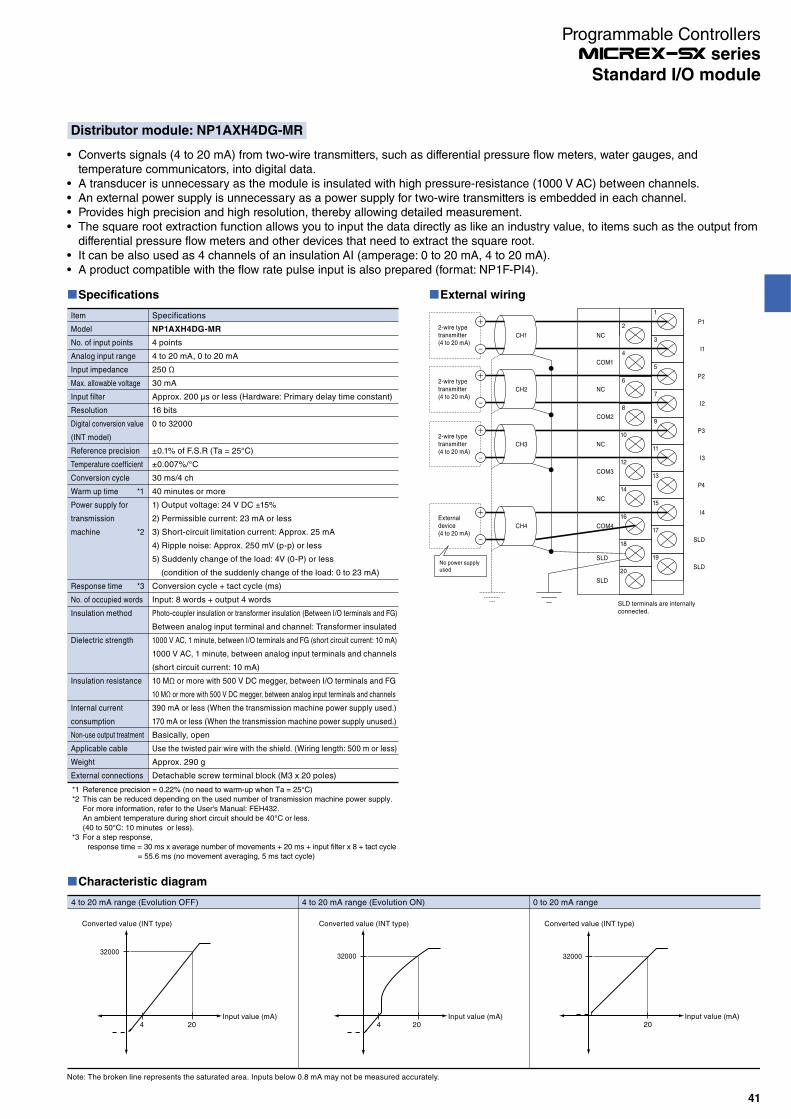
Distributor module: NP1AXH4DG-MR
Converts signals (4 to 20 mA) from two-wire transmitters, such as differential pressure flow meters, water gauges, and temperature communicators, into digital data.A transducer is unnecessary as the module is insulated with high pressure-resistance (1000 V AC) between channels.An external power supply is unnecessary as a power supply for two-wire transmitters is embedded in each channel.Provides high precision and high resolution, thereby allowing detailed measurement.The square root extraction function allows you to input the data directly as like an industry value, to items such as the output from differential pressure flow meters and other devices that need to extract the square root.It can be also used as 4 channels of an insulation AI (amperage: 0 to 20 mA, 4 to 20 mA).A product compatible with the flow rate pulse input is also prepared (format: NP1F-PI4).
Characteristic diagram
Converted value (INT type)
Input value (mA)20
32000
Converted value (INT type)
Input value (mA)4 20
32000
Note: The broken line represents the saturated area. Inputs below 0.8 mA may not be measured accurately.
4 to 20 mA range (Evolution OFF) 4 to 20 mA range (Evolution ON) 0 to 20 mA range
Converted value (INT type)
Input value (mA)4 20
32000
External wiring
2-wire type transmitter (4 to 20 mA)
+
−
1
2
4
6
8
10
12
14
16
18
20
3
5
7
9
11
13
15
17
19
CH1
2-wire type transmitter (4 to 20 mA)
+
−
CH2
2-wire type transmitter (4 to 20 mA)
+
−
CH3
External device (4 to 20 mA)
+
−
CH4
SLD terminals are internally connected.
P1
NC
COM1
NC
COM2
NC
NC
SLD
SLD
COM3
COM4
I1
P2
I2
P3
I3
P4
I4
SLD
SLDNo power supply used
Specifications
Item
Model
No. of input points
Analog input range
Input impedance
Max. allowable voltage
Input filter
Resolution
Digital conversion value
(INT model)
Reference precision
Temperature coefficient
Conversion cycle
Warm up time *1
Power supply for
transmission
machine *2
Response time *3
No. of occupied words
Insulation method
Dielectric strength
Insulation resistance
Internal current
consumption
Non-use output treatment
Applicable cable
Weight
External connections
Specifications
NP1AXH4DG-MR
4 points
4 to 20 mA, 0 to 20 mA
250 Ω
30 mA
Approx. 200 μs or less (Hardware: Primary delay time constant)
16 bits
0 to 32000
±0.1% of F.S.R (Ta = 25°C)
±0.007%/°C
30 ms/4 ch
40 minutes or more
1) Output voltage: 24 V DC ±15%
2) Permissible current: 23 mA or less
3) Short-circuit limitation current: Approx. 25 mA
4) Ripple noise: Approx. 250 mV (p-p) or less
5) Suddenly change of the load: 4V (0-P) or less
(condition of the suddenly change of the load: 0 to 23 mA)
Conversion cycle + tact cycle (ms)
Input: 8 words + output 4 words
Photo-coupler insulation or transformer insulation (Between I/O terminals and FG)
Between analog input terminal and channel: Transformer insulated
1000 V AC, 1 minute, between I/O terminals and FG (short circuit current: 10 mA)
1000 V AC, 1 minute, between analog input terminals and channels
(short circuit current: 10 mA)
10 MΩ or more with 500 V DC megger, between I/O terminals and FG
10 MΩ or more with 500 V DC megger, between analog input terminals and channels
390 mA or less (When the transmission machine power supply used.)
170 mA or less (When the transmission machine power supply unused.)
Basically, open
Use the twisted pair wire with the shield. (Wiring length: 500 m or less)
Approx. 290 g
Detachable screw terminal block (M3 x 20 poles)
*1 Reference precision = 0.22% (no need to warm-up when Ta = 25°C)
*2 This can be reduced depending on the used number of transmission machine power supply.
For more information, refer to the User's Manual: FEH432.
An ambient temperature during short circuit should be 40°C or less.
(40 to 50°C: 10 minutes or less).
*3 For a step response,
response time = 30 ms x average number of movements + 20 ms + input filter x 8 + tact cycle
= 55.6 ms (no movement averaging, 5 ms tact cycle)
41
Standard I/O module
Programmable Controllers series

SpecificationsModel NP1AYH8VHR-MR
No. of output points 8 points
Analog output range 0 to 5 V 1 to 5 V 0 to 10 V -10 to +10 V
Load impedance 500 Ω or more 1 kΩ or more
Max. resolution 1.25 mV
Digital conversion 0 to 16000 0 to 16000 -8000 to 8000
Total accuracy ±0.25% of F.S.R
Temperature coefficient ±0.007%/°C
Max. noise deviation ±0.6% of F.S.R
Conversion cycle 3.2 ms/8 points
Response time Conversion cycle + tact cycle (ms)
Load short protection Provided
No. of occupied words Input: 16 W + output: 34 W
Insulation method Between analog input terminal and FG: Photocoupler/transformer insulated
Dielectric strength 500 V AC, 1 minute, between analog output terminals and FG (short-circuit current: 10 mA)
Insulation resistance 10 MΩ or more with the 500 V DC of DC megger between total analog output terminals and FG
Internal current consumption
200 mA or less (at rated load)
Non use output treatment Basically, open
Applicable cable
Analog output cableUse an AWG #22 to 18 shielded twisted pair line.
Duplex switch signal cable (max. wire distance: 5m)Use an AWG #22 to 18 shielded straight cable.
Weight Approx. 260 g
External connections Detachable screw terminal block (M3 x 20 poles)
Dimension W35 x H105 x D111 mm (26 mm protrusion)
Characteristic diagram
Converted value (V)
16000
5
Input value (INT type)
-0.75
-2400
Converted value (V)
10000
5
Input value (INT type)-1500
-0.75
0 to 5 V range (for LSB) 0 to 5 V range (for %)
Duplex analog output module: NP1AYH8VHR-MR
Features
Duplication of analog output· Analog output can be duplicated with the duplex switch control signal.· Switching from the operation to the waiting can be performed by the application program or the front switch.· The status of operation and waiting can be confirmed with the OUT LED on the front face of the module.· The terminal block drop detection function is built in.
Duplication of analog output by the instruction from the 2-system or 3-system of controller.Operation instruction is available from controllers (max. of 3 systems) of different configurations to this module via the communication module.
Operation mode Overview
Single mode Output data are provided by 1 unit of CPU and are D/A-converted.
DUPLEX mode (CPU duplication) One of output data provided by 2 units of CPU is selected and D/A-converted.
DUAL mode (CPU duplication) A mid value is selected from output data provided by 2 units of CPU and previous output value, and D/A-converted.
Triple mode (CPU triplication) A mid value is selected from output data provided by 3 units of CPU, and D/A-converted.
High speed and high accuracyHigh-speed conversion period of 3.2 ms/8 ch and high standard accuracy of ±0.25% enable a detailed control.
42
Standard I/O module
Programmable Controllers series
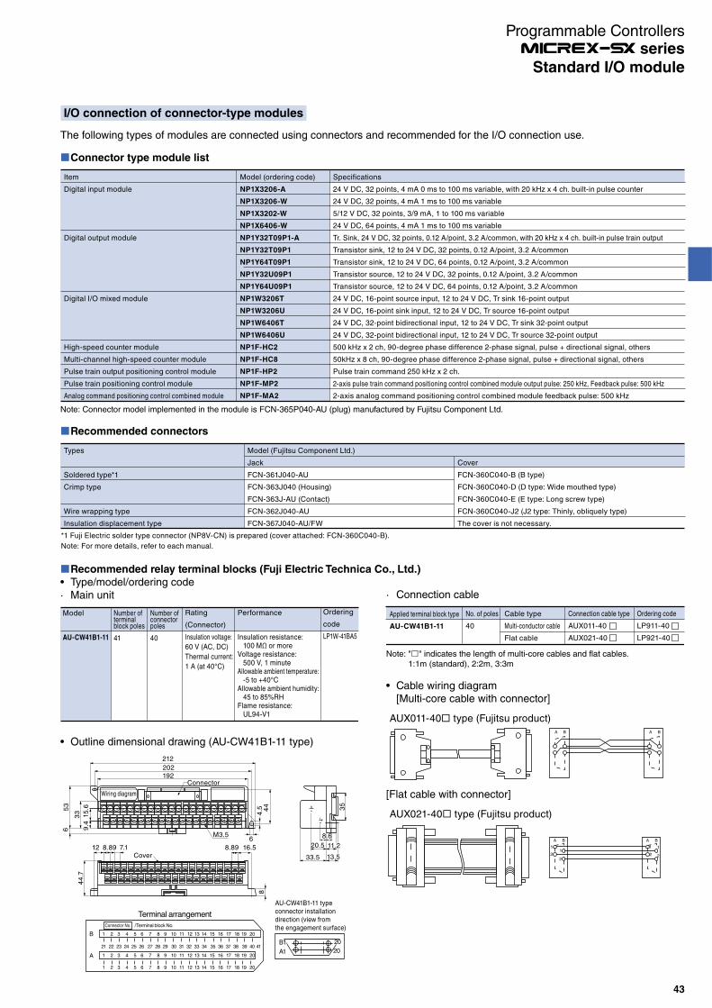
I/O connection of connector-type modules
The following types of modules are connected using connectors and recommended for the I/O connection use.
Cable wiring diagram[Multi-core cable with connector]
A B A B
AUX011-40 type (Fujitsu product)
[Flat cable with connector]
A B A B
1
21
2
1
2
1
2
AUX021-40 type (Fujitsu product)
Recommended connectors
Types
Soldered type*1
Crimp type
Wire wrapping type
Insulation displacement type
Model (Fujitsu Component Ltd.)
Jack
FCN-361J040-AU
FCN-363J040 (Housing)
FCN-363J-AU (Contact)
FCN-362J040-AU
FCN-367J040-AU/FW
Cover
FCN-360C040-B (B type)
FCN-360C040-D (D type: Wide mouthed type)
FCN-360C040-E (E type: Long screw type)
FCN-360C040-J2 (J2 type: Thinly, obliquely type)
The cover is not necessary.
*1 Fuji Electric solder type connector (NP8V-CN) is prepared (cover attached: FCN-360C040-B).
Note: For more details, refer to each manual.
Recommended relay terminal blocks (Fuji Electric Technica Co., Ltd.)
Type/model/ordering code· Main unit
Model
AU-CW41B1-11
Number of terminal block poles
41
Number of connector poles
40
Rating
(Connector)
Insulation voltage:
60 V (AC, DC)
Thermal current:
1 A (at 40°C)
Ordering
code
LP1W-41BA5
Performance
Insulation resistance: 100 MΩ or moreVoltage resistance: 500 V, 1 minuteAllowable ambient temperature: -5 to +40°CAllowable ambient humidity: 45 to 85%RHFlame resistance: UL94-V1
Outline dimensional drawing (AU-CW41B1-11 type)
212
202192
4.5 4
4
6
65
3
33
9.4
15
.6
Connector
M3.5
Wiring diagram
8
8.89 16.5Cover
7.112 8.89
44
.7
35
8.6
20.5 11.2
33.5 13.5
20
AU-CW41B1-11 typeconnector installationdirection (view fromthe engagement surface)
20
A1
B1
Terminal arrangement
Connector No. /Terminal block No.
21 22 23 24 25 26 27 28 29 30 31 32 33 34 35 36 37 38 39 40 41
1 2 3 4 5 6 7 8 9 10 11 12 13 14 15 16 17 18 19 20
1 2 3 4 5 6 7 8 9 10 11 12 13 14 15 16 17 18 19 20
1 2 3 4 5 6 7 8 9 10 11 12 13 14 15 16 17 18 19 20
B
A
Note: Connector model implemented in the module is FCN-365P040-AU (plug) manufactured by Fujitsu Component Ltd.
Connector type module list
Item
Digital input module
Digital output module
Digital I/O mixed module
High-speed counter module
Multi-channel high-speed counter module
Pulse train output positioning control module
Pulse train positioning control module
Analog command positioning control combined module
Model (ordering code)
NP1X3206-A
NP1X3206-W
NP1X3202-W
NP1X6406-W
NP1Y32T09P1-A
NP1Y32T09P1
NP1Y64T09P1
NP1Y32U09P1
NP1Y64U09P1
NP1W3206T
NP1W3206U
NP1W6406T
NP1W6406U
NP1F-HC2
NP1F-HC8
NP1F-HP2
NP1F-MP2
NP1F-MA2
Specifications
24 V DC, 32 points, 4 mA 0 ms to 100 ms variable, with 20 kHz x 4 ch. built-in pulse counter
24 V DC, 32 points, 4 mA 1 ms to 100 ms variable
5/12 V DC, 32 points, 3/9 mA, 1 to 100 ms variable
24 V DC, 64 points, 4 mA 1 ms to 100 ms variable
Tr. Sink, 24 V DC, 32 points, 0.12 A/point, 3.2 A/common, with 20 kHz x 4 ch. built-in pulse train output
Transistor sink, 12 to 24 V DC, 32 points, 0.12 A/point, 3.2 A/common
Transistor sink, 12 to 24 V DC, 64 points, 0.12 A/point, 3.2 A/common
Transistor source, 12 to 24 V DC, 32 points, 0.12 A/point, 3.2 A/common
Transistor source, 12 to 24 V DC, 64 points, 0.12 A/point, 3.2 A/common
24 V DC, 16-point source input, 12 to 24 V DC, Tr sink 16-point output
24 V DC, 16-point sink input, 12 to 24 V DC, Tr source 16-point output
24 V DC, 32-point bidirectional input, 12 to 24 V DC, Tr sink 32-point output
24 V DC, 32-point bidirectional input, 12 to 24 V DC, Tr source 32-point output
500 kHz x 2 ch, 90-degree phase difference 2-phase signal, pulse + directional signal, others
50kHz x 8 ch, 90-degree phase difference 2-phase signal, pulse + directional signal, others
Pulse train command 250 kHz x 2 ch.
2-axis pulse train command positioning control combined module output pulse: 250 kHz, Feedback pulse: 500 kHz
2-axis analog command positioning control combined module feedback pulse: 500 kHz
Note: " " indicates the length of multi-core cables and flat cables.1:1m (standard), 2:2m, 3:3m
· Connection cable
Applied terminal block type
AU-CW41B1-11
No. of poles
40
Cable type
Multi-conductor cable
Flat cable
Connection cable type
AUX011-40
AUX021-40
Ordering code
LP911-40
LP921-40
43
Standard I/O module
Programmable Controllers series

Recommended relay terminal blocks (Fuji Electric Technica Co., Ltd.)
Specifications
Model
(ordering code)
LP5W-40H1
Number of terminal block poles
40
M3 screw
Supported by screws
Standard tightening torque:
1.2N·m
Compliant cable: Up to
1.25mm2
Connector
No. of poles
40
Mounted connector:
FCN-364P040-AU (plug)
Fujitsu Component Ltd.
Flame resistance: UL94V-0 rating
Insulation voltage:
125 V (AC, DC)
Rated thermal current: 1A
Performance
Insulation resistance: 100 MΩ or more
Voltage resistance: For 1 min. at 600 V
Allowable ambient temperature: -10 to +50°C
Flame resistance: UL94V-0
Outline dimensional drawing
35
6.35 1.27 7.62
26
14
2- 4.5(For mounting holes)
Connector Lever switch for detaching rail162
120
36.8
33
40
10
36
33
40
10
Wiring diagram
B1 B2 B3 B4 B5 B6 B7 B8 B9 B10 B11 B12 B13 B14 B15 B16 B17 B18 B19 B20
B1 B2 B3 B4 B5 B6 B7 B8 B9 B10 B11 B12 B13 B14 B15 B16 B17 B18 B19 B20
A1 A2 A3 A4 A5 A6 A7 A8 A9 A10 A11 A12 A13 A14 A15 A16 A17 A18 A19 A20
A1 A2 A3 A4 A5 A6 A7 A8 A9 A10 A11 A12 A13 A14 A15 A16 A17 A18 A19 A20
Connector
Terminalblock
Applicable connector
Types
Soldered type*1
Crimp type
Wire wrapping type
Insulation displacement type
Model (Fujitsu Component Ltd.)
Jack
FCN-361J040-AU
FCN-363J040 (Housing)
FCN-363J-AU (Contact)
FCN-362J040-AU
FCN-367J040-AU/FW
Cover
FCN-360C040-B (B type)
FCN-360C040-D (D type: Wide mouthed type)
FCN-360C040-E (E type: Long screw type)
The cover is not necessary.
*1 Fuji Electric solder type connector (NP8V-CN) is prepared (cover attached: FCN-360C040-B).
Note: For more details, refer to each manual.
44
Standard I/O module
Programmable Controllers series
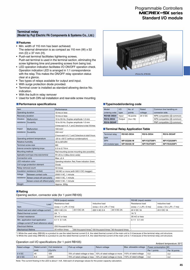
(Picture No. AF96-82)
Performance specifications
Item
Operating duration
Recovery duration
Vibration
resistance
Impact
resistance
Operating ambient temperature
Relative humidity
Terminal screw size
External connection tightening torque
Mounting method
Applicable round-type crimp-style terminal
Connection wire
LED indication color
Coil surge protection element
Relay removal count
Insulation resistance (initial)
Voltage
resistance
Weight
Malfunction
Durability
Malfunction
Durability
Between contact coils
Between contacts with same polarity
Between contacts with different polarity
Performance
10 ms or less
10 ms or less
10 to 55 Hz, Duplex amplitude 1.0 mm
10 to 55 Hz, Duplex amplitude 1.0 mm
3 times each in X, Y, and Z directions to total 18 times
100 m/s2
200 m/s2
2 hours each in X, Y, and Z directions to total 6 hours
-25 to +55˚C (without condensation)
35 to 85%RH
M3
0.5 to 0.7 N∙m
Rail mounting (screw mounting also possible)
R1.25 to 3 (Max.6mm wide)
Max. 1.4
Operating indication: Red, Power indication: Green
Diode
50 times
100 MΩ or more (with 500 V DC megger)
2000 V AC, 1 minute
1000 V AC, 1 minute
2000 V AC, 1 minute
Approx. 200g
Type/model/ordering code
Model
(ordering code)
RS16E-DE04
RS16-DE04
RS16-DE04P
I/O
type
Input
Output
No. of
points
16 points
(1a x 16)
Rated
voltage
24 V DC
Common line handling on
connector side.
NPN compatible ( common)
NPN compatible ( common)
PNP compatible ( common)
Terminal Relay Application Table
Terminal relay
type
SPH
I/O module type
RS16E-DE04
NP1X3206-W
NP1X6406-W
RS16-DE04
NP1Y32T09P1
NP1Y64T09P1
RS16-DE04P
NP1Y32U09P1
NP1Y64U09P1
Rating
Opening section, connector side (for 1 point RB105)
Item
Rated load and rated voltage current
Rated thermal current
Contact resistance
Min. application load application
voltage current (P level reference value)
Electrical lifetime
Mechanical lifetime
RS16 (output) resistor
Resistance load
(cos = 1, L/R = 0 ms)
220 V AC 2 A
2A *1
30 mΩ or less
0.1 V 0.1 mA
200 thousand times
20 million times 300 thousand times 100 thousand times 60 thousand times
Inductive load
(cos = 0.4, L/R = 7 ms)
220 V AC 2 A
RS16E (input) resistor
Resistance load
(cos = 1, L/R = 0 ms)
24 V DC 1A
1A *2
30 mΩ or less
0.1 V 0.1 mA
-
Inductive load
(cos = 0.4, L/R = 7 ms)
24 V DC 1A
*1 While the used relay (RB105) is a product to use the rated thermal current 5 A, the rated thermal current of the main unit is 2 A because of the terminal relay unit structure.*2 While the used relay (RB105) is a product to use the rated thermal current 5 A, the rated thermal current of the main unit is 1 A because of the terminal relay unit structure.
24 V DC 2A 24 V DC 2A
Load
Features
Min. width of 110 mm has been achieved.The external dimension is as compact as 110 mm (W) x 52 mm (D) x 37 mm (H).Push-set terminal facilitates tightening screws.Push-set terminal is used in the terminal section, eliminating the screw tightening time and preventing screws from being lost.LED operation indication facilitates I/O ON/OFF operation check.Operation indication LED is arranged in 1:1 correspondence with the relay. This makes the ON/OFF relay operation status clear at a glance.Two types of relays available for output and input.With surge protection diode provided.Terminal cover is installed as standard allowing device No. indication.With the built-in relay removerUsed for both DIN rail installation and rear-side screw mounting
Terminal relay(Model by Fuji Electric FA Components & Systems Co., Ltd.)
Ambient temperature: 20°COperation coil I/O specifications (for 1 point RB105)
Rated voltage
5 V DC
24 V DC
Rated current
[mA]
40
8.3
Coil resistance
[Ω]±10%
125
2,880
Pick-up voltage
70% of rated voltage or less
70% of rated voltage or less
Return voltage
10% of rated voltage or more
10% of rated voltage or more
Max. allowable voltage
110% of rated voltage
110% of rated voltage
Power consumption [W]
Per 1 points
0.2
0.2
Per 16 points
3.2
3.2
Note: The current flowing in the LED is about 1 mA. Add each of amperage values for the power capacity calculation.
45
Standard I/O module
Programmable Controllers series
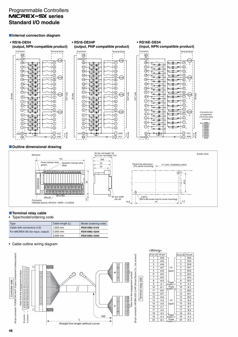
Internal connection diagram
-
-
E
F
D
C
A
B
9
8
6
7
5
4
2
3
1
0
COM
COM
COM
COM
+-
GND
GND
VCC
VCC
Connector
Connector pinarrangement
(Terminal-relaycommon)
20191817161514131211
10987654321
20
10
18
17
16
15
14
13
12
11
8
7
6
5
4
3
2
1
9
19
Terminal block
RS16-DE04
(output, NPN compatible product)
COM
COM
COM
COM
+-
GND
GND
VCC
VCC
Connector
19
9
18
17
16
15
14
13
12
11
8
7
6
5
4
3
2
1
10
20
Terminal block
RS16-DE04P
(output, PNP compatible product)
E
F
D
C
A
B
9
8
6
7
5
4
2
3
1
0
E
F
D
C
A
B
9
8
6
7
5
4
2
3
1
0
COM
COM
COM
COM
-
+
+
+
+
+
-
-
-
-
-
-
-
-
-
-
-
-
-
-
GNDGND
VCC
VCC
Connector
20
10
18
17
16
15
14
13
12
11
8
7
6
5
4
3
2
1
9
19
Terminal block
RS16E-DE04
(input, NPN compatible product)
IN s
ide
OU
T s
ide
IN s
ide
IN s
ide
IN s
ide
IN s
ide
OU
T s
ide
OU
T s
ide
IN s
ide
Terminal relay cableType/model/ordering code
Type
Cable with connectors (1:2)
For MICREX-SX (for input, output)
Cable length (L)
1,000 mm
2,000 mm
3,000 mm
Model (ordering code)
RS910M2-0104
RS910M2-0204
RS910M2-0304
Outline dimensional drawing
2- 4.2(M3 to M4 screw hole for screw mounting)
14.8 91 4.2
111 (min. installation pitch)
43
.5
42.5 (for rail height 7.5)50 (for rail height 15)
ConnectorHIROSE Electric HIF3CA—20PA—2.54DSA
M3×22
Power indicator lamp(green)
Operation indicator lamp(Red)
110
4.7
52
Remover
Panel hole dimension(For panel-mounting)
35 mm widthJIS rail
33
37
(39)
[Units: mm]
Cable outline wiring diagram
Co
ntr
olle
r sid
e
Te
rmin
al re
lay s
ide
AB
20 pin (A) 40 pin
1
2
3
4
5
6
7
8
9
10
11
12
13
14
15
16
17
18
19
20
A20
A19
A18
A17
A16
A15
A14
A13
A 1
B 1
A12
A11
A10
A 9
A 8
A 7
A 6
A 5
A 3
B 3
I/O
signal
I/O
signal
20 pin (B) 40 pin
1
2
3
4
5
6
7
8
9
10
11
12
13
14
15
16
17
18
19
20
B20
B19
B18
B17
B16
B15
B14
B13
A 2
B 2
B12
B11
B10
B 9
B 8
B 7
B 6
B 5
A 4
B 4
Powersupply (-)
Powersupply (+)
Powersupply (-)
Powersupply (+)
Vie
w f
rom
th
e e
ng
ag
em
en
t su
rfa
ce
20
-pin
co
nn
ecto
r: H
IF3
BA
-20
D-2
.54
R (
Hir
ose E
lectr
ic C
o., L
td. p
rod
uct)
40
-pin
co
nn
ecto
r: F
CN
36
7J4
0-A
U/F
(F
ujit
su C
om
po
ne
nt L
imite
d p
rod
uct)
Vie
w f
rom
th
e e
ng
ag
em
en
t su
rfa
ce
B c
olu
mn
A c
olu
mn
<Wiring>
L150
Straight line length (without curve)
2019
1817
1615
1413
1211
109
87
65
43
21
2019
1817
1615
1413
1211
109
87
65
43
21
2019
1817
1615
1413
1211
109
87
65
43
21
2019
1817
1615
1413
1211
109
87
65
43
21
46
Standard I/O module
Programmable Controllers series
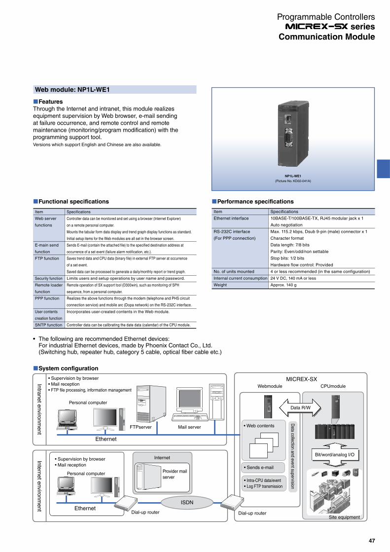
Web module: NP1L-WE1
Features
Through the Internet and intranet, this module realizes equipment supervision by Web browser, e-mail sending at failure occurrence, and remote control and remote maintenance (monitoring/program modification) with the programming support tool.Versions which support English and Chinese are also available.
NP1L-WE1
(Picture No. KD02-041A)
Performance specifications
Item
Ethernet interface
RS-232C interface
(For PPP connection)
No. of units mounted
Internal current consumption
Weight
Specifications
10BASE-T/100BASE-TX, RJ45 modular jack x 1
Auto negotiation
Max. 115.2 kbps, Dsub 9-pin (male) connector x 1
Character format
Data length: 7/8 bits
Parity: Even/odd/non settable
Stop bits: 1/2 bits
Hardware flow control: Provided
4 or less recommended (in the same configuration)
24 V DC, 140 mA or less
Approx. 140 g
Functional specifications
Item
Web server
functions
E-main send
function
FTP function
Security function
Remote loader
function
PPP function
User contents
creation function
SNTP function
Specifications
Controller data can be calibrating the date data (calendar) of the CPU module.
Incorporates user-created contents in the Web module.
Realizes the above functions through the modem (telephone and PHS circuit
connection service) and mobile arc (Dopa network) on the RS-232C interface.
Remote operation of SX support tool (D300win), such as monitoring of SPH
sequence, from a personal computer.
Saves trend data and CPU data (binary file) in external FTP server at occurrence
of a set event.
Saved data can be processed to generate a daily/monthly report or trend graph.
Limits users and setup operations by user name and password.
Sends E-mail (contain the attached file) to the specified destination address at
occurrence of a set event (failure alarm notification, etc.).
Controller data can be monitored and set using a browser (Internet Explorer)
on a remote personal computer.
Mounts the tabular form data display and trend graph display functions as standard.
Initial setup items for the Web modules are all set in the browser screen.
The following are recommended Ethernet devices:For industrial Ethernet devices, made by Phoenix Contact Co., Ltd.(Switching hub, repeater hub, category 5 cable, optical fiber cable etc.)
System configuration
Intra
ne
t enviro
nm
en
tIn
tern
et e
nviro
nm
en
t
Supervision by browser
Mail reception
FTP file processing, information management
FTPserver Mail server
Ethernet
Webmodule CPUmodule
MICREX-SX
Sends e-mail
Intra-CPU data/event
Log FTP transmission
Data collection and event supervision
Supervision by browser
Mail reception
Personal computer
Dial-up routerEthernet
Internet
Personal computer
Bit/word/analog I/O
ISDN
Data R/W
Provider mail
server
Site equipmentDial-up router
Web contents
47
Communication Module
Programmable Controllers series
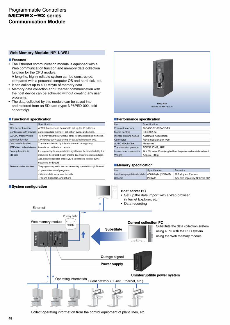
Web Memory Module: NP1L-WS1
Features
The Ethernet communication module is equipped with a Web communication function and memory data collection function for the CPU module.A long-life, highly reliable system can be constructed, compared with a personal computer OS and hard disk, etc.It can collect up to 400 Mbyte of memory data.Memory data collection and Ethernet communication with the host device can be achieved without creating any user programs.The data collected by this module can be saved into and restored from an SD card (type: NP8PSD-002, sold separately).
NP1L-WS1
(Picture No. KDD15-001)
Performance specification
Item
Ethernet interface
Media control
Interface switching method
Connector
AUTO MDI/MDI-X
Transmission protocol
Internal current consumption
Weight
Specification
10BASE-T/100BASE-TX
IEEE802.3u
Automatic negotiation
RJ45 modular jack type
Measures
TCP/IP, ICMP, ARP
24 V DC, below 80 mA (supplied from the power module via base board)
Approx. 140 g
Memory specification
Item
Internal memory capacity for data collection
SD card
Specification
400 Mbyte (SDRAM)
2 Gbyte
Remarks
200 Mbyte x 2 areas
Type sold separately: NP8PSD-002
Functional specification
Item
Web server function
(configurable with browser)
SX CPU memory data
collection function
Data transfer function
(FTP client) to host device
Backup function to
SD card
Remote loader function
Specification
A Web browser can be used to set up the IP address,
collection data memory, collection cycle, and others.
The memory data of the CPU module can be regularly collected into this module.
A Web browser can be used to set up the data collection area and cycle.
The data collected by this module can be regularly
transferred to the host device.
It is triggered by the outage detection signal to save the data collected by this
module into the SD card, thereby enabling data preservation during outages.
Also, the switch operation enables you to save the data collected by this
module into the SD card.
The programming assist tool can be remotely operated through Ethernet.
· Upload/download programs
· Monitor data in various formats
· Failure diagnosis, and others
System configuration
Ethernet
Primary buffer
Client network (FL-net, Ethernet, etc.)Operating information
Substitute the data collection system
using a PC with the PLC system
using the Web memory module
Host server PC
Set up the data import with a Web browser (Internet Explorer, etc.)Data recording
Web memory module
Uninterruptible power system
Outage signal
Power supply
Substitute
Current collection PC
Collect operating information from the control equipment of plant lines, etc.
400MB
48
Communication Module
Programmable Controllers series
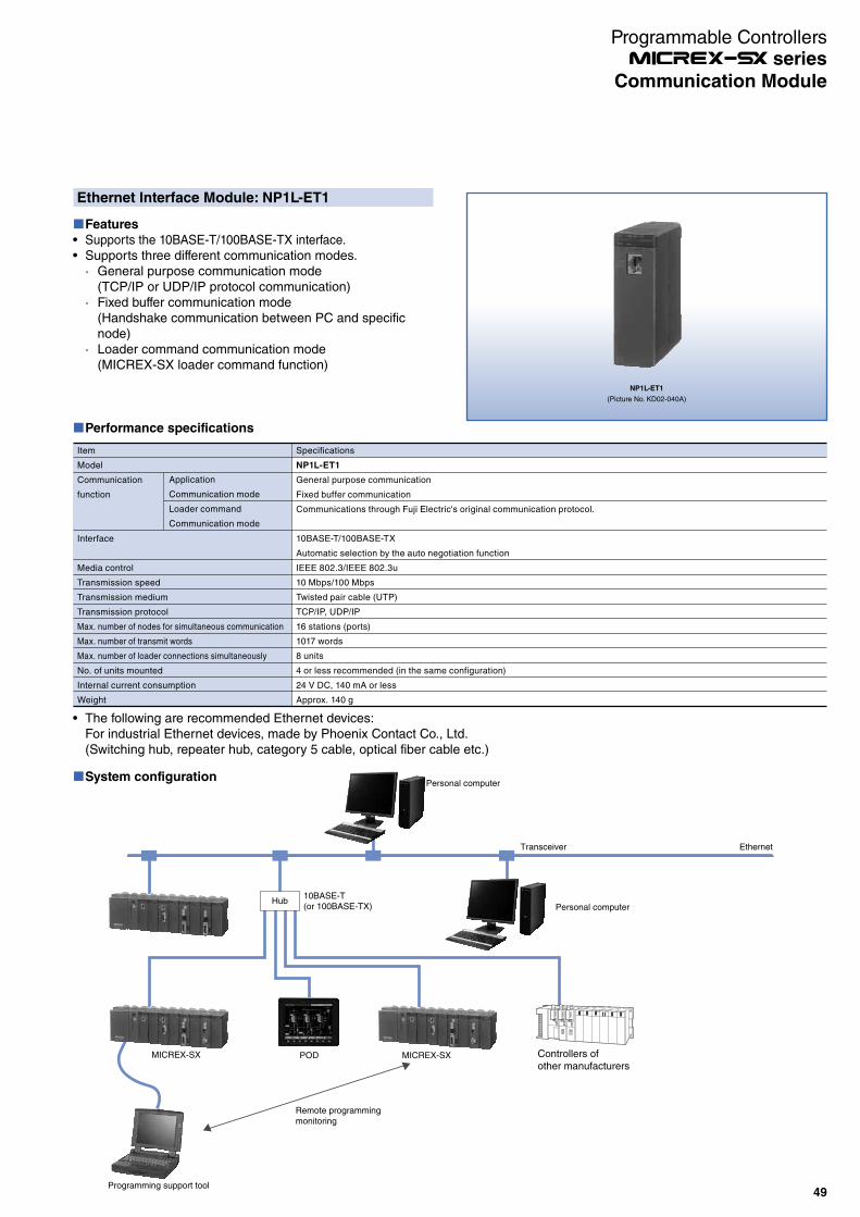
Performance specifications
Item
Model
Communication
function
Interface
Media control
Transmission speed
Transmission medium
Transmission protocol
Max. number of nodes for simultaneous communication
Max. number of transmit words
Max. number of loader connections simultaneously
No. of units mounted
Internal current consumption
Weight
Application
Communication mode
Loader command
Communication mode
Specifications
NP1L-ET1
General purpose communication
Fixed buffer communication
Communications through Fuji Electric's original communication protocol.
10BASE-T/100BASE-TX
Automatic selection by the auto negotiation function
IEEE 802.3/IEEE 802.3u
10 Mbps/100 Mbps
Twisted pair cable (UTP)
TCP/IP, UDP/IP
16 stations (ports)
1017 words
8 units
4 or less recommended (in the same configuration)
24 V DC, 140 mA or less
Approx. 140 g
Ethernet Interface Module: NP1L-ET1
Features
Supports the 10BASE-T/100BASE-TX interface.Supports three different communication modes.· General purpose communication mode
(TCP/IP or UDP/IP protocol communication)· Fixed buffer communication mode
(Handshake communication between PC and specific node)
· Loader command communication mode(MICREX-SX loader command function)
NP1L-ET1
(Picture No. KD02-040A)
The following are recommended Ethernet devices:For industrial Ethernet devices, made by Phoenix Contact Co., Ltd.(Switching hub, repeater hub, category 5 cable, optical fiber cable etc.)
System configuration
Hub
EthernetTransceiver
Remote programming monitoring
Programming support tool
Controllers of other manufacturers
10BASE-T(or 100BASE-TX)
Personal computer
Personal computer
MICREX-SX POD MICREX-SX
49
Communication Module
Programmable Controllers series

System configuration
NP1L-FL3
(Picture No. KDD05-017)
The following are recommended Ethernet devices:For industrial Ethernet devices, made by Phoenix Contact Co., Ltd.(Switching hub, repeater hub, category 5 cable, optical fiber cable etc.)
FL-net Ver. 3 (100 Mbps adaption) Module: NP1L-FL3
Features
Up to 8 communication modules including P/PE-link can be installed on the base board equipped with CPU. (For SPH200, up to two modules)Data exchange between processorsCyclic data communication, message communicationFL-net loader commands supportedSX system loader functions via network are supported.
FL-net
MICREX-SX
Remote programming monitoring
Programming support tool
Personal computer
MICREX-SX MICREX-SX Controllers of other manufacturers
Performance specifications
Item
Model
Transmission specifications
No. of SX bus connectable modules
Max. number of system nodes
Transmission line form
Framing method
Access control
Transmission system (code)
Transmission speed
Max. segment length
Protocol
IP address
Data exchange method
Host interface
Internal current consumption
Weight
Specifications
NP1L-FL3
10BASE-T / 100BASE-TX
Max. 8 units/configuration (including P/PE-link)
254 units (2 units / segment, including HUB)
Bus configuration (multi-drop)
Ethernet II
CSMA/CD
Base band (Manchester coding)
10 Mbps/100 Mbps
100 m: between node and HUB (Max. 200 m with repeater)
FA link protocol, UDP/IP, ICMP, ARP
Class C
· Cyclic broadcast transmission method
· Data size: Max. 8.5 Kwords
· Message transmission type
· Data size: Max. 512 words
Common memory cyclic refresh method, block data read / write
24 V DC, 160 mA or less
Approx. 220 g
50
Communication Module
Programmable Controllers series
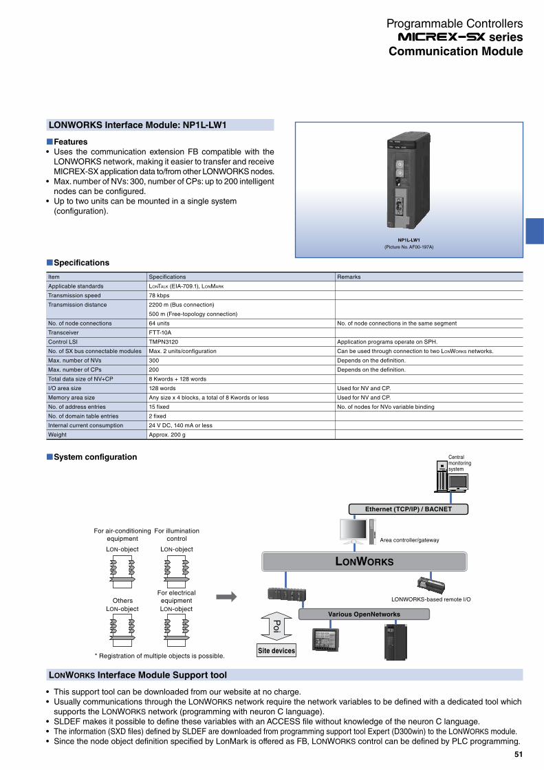
LONWORKS Interface Module: NP1L-LW1
Features
Uses the communication extension FB compatible with the LONWORKS network, making it easier to transfer and receive MICREX-SX application data to/from other LONWORKS nodes.Max. number of NVs: 300, number of CPs: up to 200 intelligent nodes can be configured.Up to two units can be mounted in a single system (configuration).
NP1L-LW1
(Picture No. AF00-197A)
LONWORKS Interface Module Support tool
This support tool can be downloaded from our website at no charge.Usually communications through the LONWORKS network require the network variables to be defined with a dedicated tool which supports the LONWORKS network (programming with neuron C language).SLDEF makes it possible to define these variables with an ACCESS file without knowledge of the neuron C language.The information (SXD files) defined by SLDEF are downloaded from programming support tool Expert (D300win) to the LONWORKS module.Since the node object definition specified by LonMark is offered as FB, LONWORKS control can be defined by PLC programming.
System configuration
Ethernet (TCP/IP) / BACNET
LONWORKS
Various OpenNetworks
For air-conditioningequipment
LON-object
LON-object
For illuminationcontrol
LON-object
For electricalequipment
LON-object
Others
Site devices
Po
i
Area controller/gateway
LONWORKS-based remote I/O
* Registration of multiple objects is possible.
Centralmonitoringsystem
Specifications
Item
Applicable standards
Transmission speed
Transmission distance
No. of node connections
Transceiver
Control LSI
No. of SX bus connectable modules
Max. number of NVs
Max. number of CPs
Total data size of NV+CP
I/O area size
Memory area size
No. of address entries
No. of domain table entries
Internal current consumption
Weight
Specifications
LONTALK (EIA-709.1), LONMARK
78 kbps
2200 m (Bus connection)
500 m (Free-topology connection)
64 units
FTT-10A
TMPN3120
Max. 2 units/configuration
300
200
8 Kwords + 128 words
128 words
Any size x 4 blocks, a total of 8 Kwords or less
15 fixed
2 fixed
24 V DC, 140 mA or less
Approx. 200 g
Remarks
No. of node connections in the same segment
Application programs operate on SPH.
Can be used through connection to two LONWORKS networks.
Depends on the definition.
Depends on the definition.
Used for NV and CP.
Used for NV and CP.
No. of nodes for NVo variable binding
51
Communication Module
Programmable Controllers series
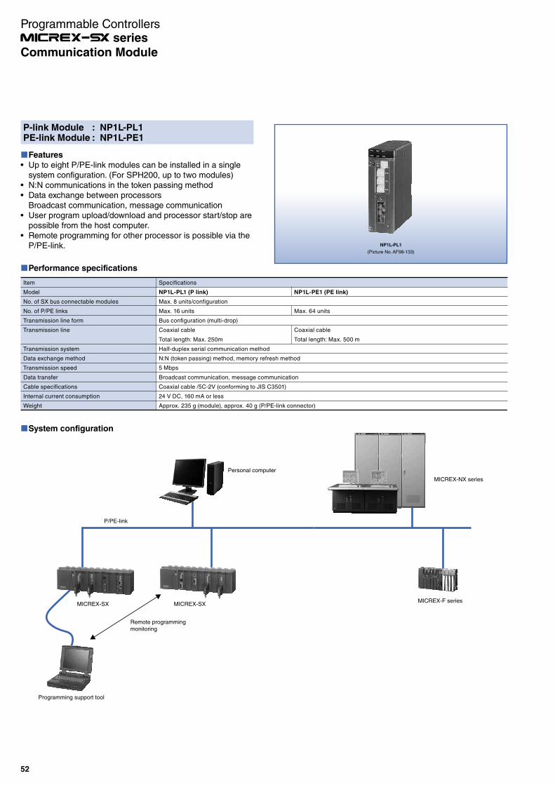
P-link Module : NP1L-PL1PE-link Module : NP1L-PE1
Features
Up to eight P/PE-link modules can be installed in a single system configuration. (For SPH200, up to two modules)N:N communications in the token passing methodData exchange between processorsBroadcast communication, message communicationUser program upload/download and processor start/stop are possible from the host computer.Remote programming for other processor is possible via the P/PE-link. NP1L-PL1
(Picture No. AF98-133)
Performance specifications
Item
Model
No. of SX bus connectable modules
No. of P/PE links
Transmission line form
Transmission line
Transmission system
Data exchange method
Transmission speed
Data transfer
Cable specifications
Internal current consumption
Weight
Specifications
NP1L-PL1 (P link)
Max. 8 units/configuration
Max. 16 units
Bus configuration (multi-drop)
Coaxial cable
Total length: Max. 250m
Half-duplex serial communication method
N:N (token passing) method, memory refresh method
5 Mbps
Broadcast communication, message communication
Coaxial cable /5C-2V (conforming to JIS C3501)
24 V DC, 160 mA or less
Approx. 235 g (module), approx. 40 g (P/PE-link connector)
NP1L-PE1 (PE link)
Max. 64 units
Coaxial cable
Total length: Max. 500 m
System configuration
MICREX-NX series
P/PE-link
MICREX-SX
Remote programming monitoring
Programming support tool
MICREX-F series
Personal computer
MICREX-SX
52
Communication Module
Programmable Controllers series
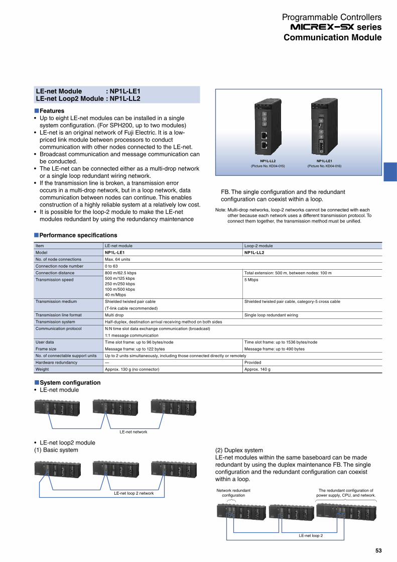
NP1L-LL2
(Picture No. KD04-015)
NP1L-LE1
(Picture No. KD04-016)
LE-net Module : NP1L-LE1LE-net Loop2 Module : NP1L-LL2
Features
Up to eight LE-net modules can be installed in a single system configuration. (For SPH200, up to two modules)LE-net is an original network of Fuji Electric. It is a low-priced link module between processors to conduct communication with other nodes connected to the LE-net.Broadcast communication and message communication can be conducted.The LE-net can be connected either as a multi-drop network or a single loop redundant wiring network.If the transmission line is broken, a transmission error occurs in a multi-drop network, but in a loop network, data communication between nodes can continue. This enables construction of a highly reliable system at a relatively low cost.It is possible for the loop-2 module to make the LE-net modules redundant by using the redundancy maintenance
Performance specifications
Item
Model
No. of node connections
Connection node number
Connection distance
Transmission speed
Transmission medium
Transmission line format
Transmission system
Communication protocol
User data
Frame size
No. of connectable support units
Hardware redundancy
Weight
LE-net module
NP1L-LE1
Max. 64 units
0 to 63
800 m/62.5 kbps
500 m/125 kbps
250 m/250 kbps
100 m/500 kbps
40 m/Mbps
Shielded twisted pair cable
(T-link cable recommended)
Multi drop
Half-duplex, destination arrival receiving method on both sides
N:N time slot data exchange communication (broadcast)
1:1 message communication
Time slot frame: up to 96 bytes/node
Message frame: up to 122 bytes
Up to 2 units simultaneously, including those connected directly or remotely
—
Approx. 130 g (no connector)
Loop-2 module
NP1L-LL2
Total extension: 500 m, between nodes: 100 m
5 Mbps
Shielded twisted pair cable, category-5 cross cable
Single loop redundant wiring
Time slot frame: up to 1536 bytes/node
Message frame: up to 490 bytes
Provided
Approx. 140 g
FB. The single configuration and the redundant configuration can coexist within a loop.
Note: Multi-drop networks, loop-2 networks cannot be connected with each other because each network uses a different transmission protocol. To connect them together, the transmission method must be unified.
System configuration
LE-net module
LE-net network
LE-net loop2 module(1) Basic system
LE-net loop 2 network
(2) Duplex systemLE-net modules within the same baseboard can be made redundant by using the duplex maintenance FB. The single configuration and the redundant configuration can coexist within a loop.
LE-net loop 2
Network redundantconfiguration
The redundant configuration ofpower supply, CPU, and network.
53
Communication Module
Programmable Controllers series

NP1L-RS1
(Picture No. AF01-93)
General Purpose Communication Module: NP1L-RS
Features
Can be combined with an extension FB for communications with diverse equipment without creating any communication control program.Communication port can be used as the loader connection port, which is effective in debugging from the SX bus expansion side installed at a distance.
Performance specifications
Communication port type by module type
Model
Communication port
NP1L-RS1
RS-232C x 1 channel
RS-485 x 1 channels
NP1L-RS2
RS-232C x 1 channel
NP1L-RS3
RS-232C x 2 channels
NP1L-RS4
RS-485 x 1 channel
NP1L-RS5
RS-485 x 2 channels
Communication port specifications
Item
Port
No. of SX bus connectable modules
Transmission system
Synchronization method
Transmission speed
Transmission distance
No. of connectable modules
Connection method
Transmission method
Internal current consumption (24 V DC)
Weight
Specifications
RS-232C
Max. 16 units/configuration
Half-duplex /serial communication method*1
Start-stop synchronous transmission
300/600/1,200/2,400/4,800/9,600/19,200/38,400/57,600/76,800/115,200 bps (115,200 bps or less in total of 2 channels) *2
15 m or less
1:1 (including one external device)
D-sub, 9-pin connector (female)
Depends on the application program (Expansion FB) in the CPU module
NP1L-RS1: 110 mA or less, NP1L-RS2: 90 mA or less, NP1L-RS3: 110 mA or less, NP1L-RS4: 80 mA or less, NP1L-RS5: 110 mA or less
NP1L-RS1: Approx. 170 g, NP1L-RS2: Approx. 160 g, NP1L-RS3: Approx. 140 g, NP1L-RS4: Approx. 160 g, NP1L-RS5: Approx. 190 g
RS-485
1 km or less (transmission speed : 19,200 bps or less)
1:N (Max. 31)
D-sub, 9-pin connector (male) Screw terminal block (M3) 20 poles (NP1L-RS5)
*1 The use of the non-procedure FB allows full-duplex communication on applications.*2 For transmission speeds of 300, 600, 76800, and 115200 bps, use FBs corresponding to the transmission speed.
System configuration
Support tool network function
Use of general-purpose communication modules makes it possible for multiple systems to be supported with one unit of personal computer loader or to remotely support the system via a modem.
MICREX-SX MICREX-SXMICREX-SX
Modem
Modem Programming support tool
RS-232C equipment including personal computer and barcode reader
RS-485 equipment
Communication software is described in the programs as an extended FB and stored in the CPU module.
MICREX-SX
MICREX-SX
54
Communication Module
Programmable Controllers series
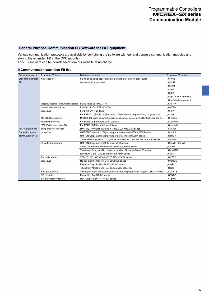
General Purpose Communication FB Software for FA Equipment
Various communication protocols are available by combining the software with general purpose communication modules and storing the extended FB in the CPU module.This FB software can be downloaded from our website at no charge.
Communication extension FB list
Package category
Standard extension
FB
For FA equipment
General-purpose
communication FB
Extension FB type
No procedure
Temperature controller communication procedure
Inverter communication
procedure
MODBUS procedure
M0DBUS Ethernet
(TCP/IP) Communication FB
Temperature controller
procedure
ID system procedure
Bar code reader
procedure
SECS procedure
NC procedure
Serial printer procedure
Relevant equipment
FB which enables application programs to execute non-procedural
communication protocols.
Fuji Electric Co.: PYX, PYH
Fuji Electric Co.: FRENIC5000
For FVR-C11 (FGI-BUS)
For FVR-C11 (FGI-BUS) (Reduction of communication processing program size)
MICREX-SX works as a master station and communicates with MODBUS slave stations.
For M0DBUS Ethernet master stations
For M0DBUS Ethernet slave stations
RKC INSTRUMENT INC.: REX-F, REX-D, FAREX-SR series
OMRON Corporation: Digital temperature controller E5AX, E5XJ series
OMRON Corporation: Digital temperature controller E5CK series
Yamatake‐Honeywell Co.: Digitronik temperature controller SDC40A/40G series
OMRON Corporation: V600 series, V700 series
Sharp Corporation: Microwave ID plate system DS series
Yamatake‐Honeywell Co.: Code recognition ID system WAM120 series
Idec Izumi Corp.: Data carrier system FP1A series
TOHKEN CO.: CD8200/8500, TLMS-3200RV series
Nippon Electric Industry Co.: BCC2600 series
Keyence Corp.: BL180, BL500, BL700 series
IZUMI DATALOGIC CO.: Bar code reader DS series
SECS-procedure semiconductor manufacturing equipment (Support: SECS- I only)
Fanuc Ltd.: FANUC Series 18i
NEC Corporation: PC-PR201 series
Extension FB name
_C_free
_Cfr252
_Cfr128
_Cfr64
_Cfr32
_Cfrpr (built-in protocol)
_Cfrp2 (built-in protocol)
_CfdPYX
_CfdFRN
_CfdFVR
_Cfvrpr
_C_modm
_C_emodm
_C_emods
_CrkREX
_ComAX
_ComCK
_CymSDC
_ComV6, _ComV7
_CshDS
_CymWAM
_CizFP
_CtkTCD
_CndBCC
_CkyBL
_CizDS
_C_SECS
_CDNC2
_C_print
55
Communication Module
Programmable Controllers series

NP1L-JP1
(Picture No. AF97-522)
OPCN-1 Master Module : NP1L-JP1OPCN-1 Slave Module : NP1L-JS1OPCN-1 Interface Module : NP1L-RJ1
Features
NP1L-JP1Up to eight units can be connected in a single system configuration.Up to 31 slave stations can be connected to a single master unit.Number of I/O points is a max. of 8192 points (512 words)For SPH200, up to 2048 points (128 words)The transmission speed can be switched. (1 M/500 k/250 k/125 kbps)
NP1L-JS1I/O data link through the OPCN-1 is possible between CPUs.Number of I/O points is a max. of 2048 points (128 words)
NP1L-RJ1Slave station configuration, conforming to the OPCN-1 Standard, implements compact, economical, centralized
*1 The transmission distance applies to T-KPEV-SB 1.25 mm2 from Furukawa Electric Co. Note that the distance may vary depending on the cable characteristics.
Communication specifications
Item
Model
Applicable class
No. of SX bus connectable modules
No. of connectable slaves
Station number setting range
Transmission line form
Transmission line
Transmission system
Transmission speed (Max. total length) *1
Encoding method
Error check
Communication function
No. of I/O points
No. of message points
Internal current consumption
Weight
Specifications
NP1L-JP1
TYPE-M51 I
Max. 8 units/configuration
31 units/master module
00 fixed
Bus configuration (multi-drop)
Shielded twisted pair cable
Half-duplex serial transmission, based on EIA RS-485
125 kbps (1000 m)/ 250 kbps (800 m)/ 500 kbps (480 m)/ 1 Mbps (240 m)
NRZI (Non Return to Zero Inverted)
ECS (X16 + X12 + X5 + 1) and retry
Initial setting service
I/O service
Reset service
JEM-TR192 service
(data read/write service)
Normal mode: Max. 2032 points (127 words)
Extension mode or I/O Extension mode: Max. 8192 points (512 words)
Max. length per transmission: 250 bytes
(data section for the data read/write service)
24 V DC, 130 mA or less
Approx. 230 g (module), approx. 40 g (OPCN-1 connector)
NP1L-RJ1
TYPE-S51 I
—
NP1L-JS1
—
01 to 7F
Initial setting service
I/O service
Reset service
Simultaneous broadcast service
Maximum input: 64 word/slave, maximum output: 64 word/slave
—
remote I/O as a multi-vendor network.Input filtering time of the input module can be set with DIP switch on the front.
System configuration
POD I/O terminal
CPU module
CPU moduleCPU module
OPCN-1 based on servo system from other manufacturers
OPCN-1 based on inverter from other manufacturers
MICREX-SXOPCN-1 assembled-type expansion unit
OPCN-1 slave system
MICREX-SX (master station)
OPCN-1 remote I/O system
OPCN-1 master module
OPCN-1 slave module
MICREX-SX (slave station) MICREX-SX (slave station)
OPCN-1Interface module
CPU module OPCN-1 master module
MICREX-SX (master station)
OPCN-1 slave module
56
Communication Module
Programmable Controllers series

DeviceNet Master Module : NP1L-DN1DeviceNet Slave Module : NP1L-DS1DeviceNet Interface Module : NP1L-RD1
Features
NP1L-DN1
Up to eight units can be connected in a single system configuration.Up to 63 units of remote I/O equipment can be connected to a single master unit.Number of I/O points is a max. of 8192 points (512 words)For SPH200, up to 2048 points (128 words)The transmission speed can be switched.125 kbps (500 m)/250 kbps (250 m)/500 kbps(100 m)
NP1L-DS1
I/O data link through the DeviceNet is possible between CPUs.Number of I/O points is a max. of 2048 points (128 words)
NP1L-DN1
(Picture No. AF99-340)
NP1L-RD1
Realizes small, economic collective remote I/O as a DeviceNet slave station.Communication specifications
Specifications
NP1L-DN1
Max. 8 units/configuration
63/master module
00 to 63
Bus configuration (multi-drop), tree-structure, branch-structure
Trunk (thick cable), drop (thin cable)
Half-duplex serial communication method
125 kbps (500 m)/ 250 kbps (250 m)/ 500 kbps(100 m)
CSMA/NBA
Base band
DC coupling-type differential Tx/Rx
Non-zero recovery using the bit stuff function NRZ (Non Return to Zero)
FCS (Frame Check Sequence CRC-16)
I/O message· Poll command/response· Change of state/Cyclic ACK not providedExplicit message(Implements the client/server function to set and diagnose remote I/O stations. Low priority communication traffic.)
319 (Fuji Electric Co., Ltd.)
Communication Adapter (Code: 0×0C)
Normal mode: Max. 2048 points (128 words)
Extension mode or I/O Extension mode: Max. 8192 points (512 words)
Max. length 492 bytes per transmission (Explicit message)
24 V DC, 45 mA or less (supplied from DeviceNet power supply)
24 V DC, 90 mA or less
Approx. 170 g
· Bit-Strobe command/response· Change of state/Cyclic ACK provided
NP1L-DS1
—
Poll command/responseExplicit message
Max. 2048 points (128 words) /1 slave
NP1L-RD1
—
Item
Model
No. of SX bus connectable modules
No. of remote I/O stations
MAC ID setting range
Transmission line form
Transmission line
Transmission system
Transmission speed (distance)
Media access control
Modulation
Media linking
Encoding method
Error check
Communication function
Vendor ID
Device type
No. of I/O points
No. of message points
Network current consumption
Internal current consumption
Weight
System configuration
DeviceNet
POD
I/O terminal
DeviceNet-based servo system from other manufacturers Inverter
DeviceNet collective extension unit
MICREX-SX
CPU module
CPU moduleCPU module
DeviceNet slave system
MICREX-SX (master station)
DeviceNet remote I/O system
DeviceNet master module
DeviceNet master module
DeviceNet slave module
MICREX-SX (slave station) MICREX-SX (slave station)
DeviceNet slave module
DeviceNet interface module
57
Communication Module
Programmable Controllers series
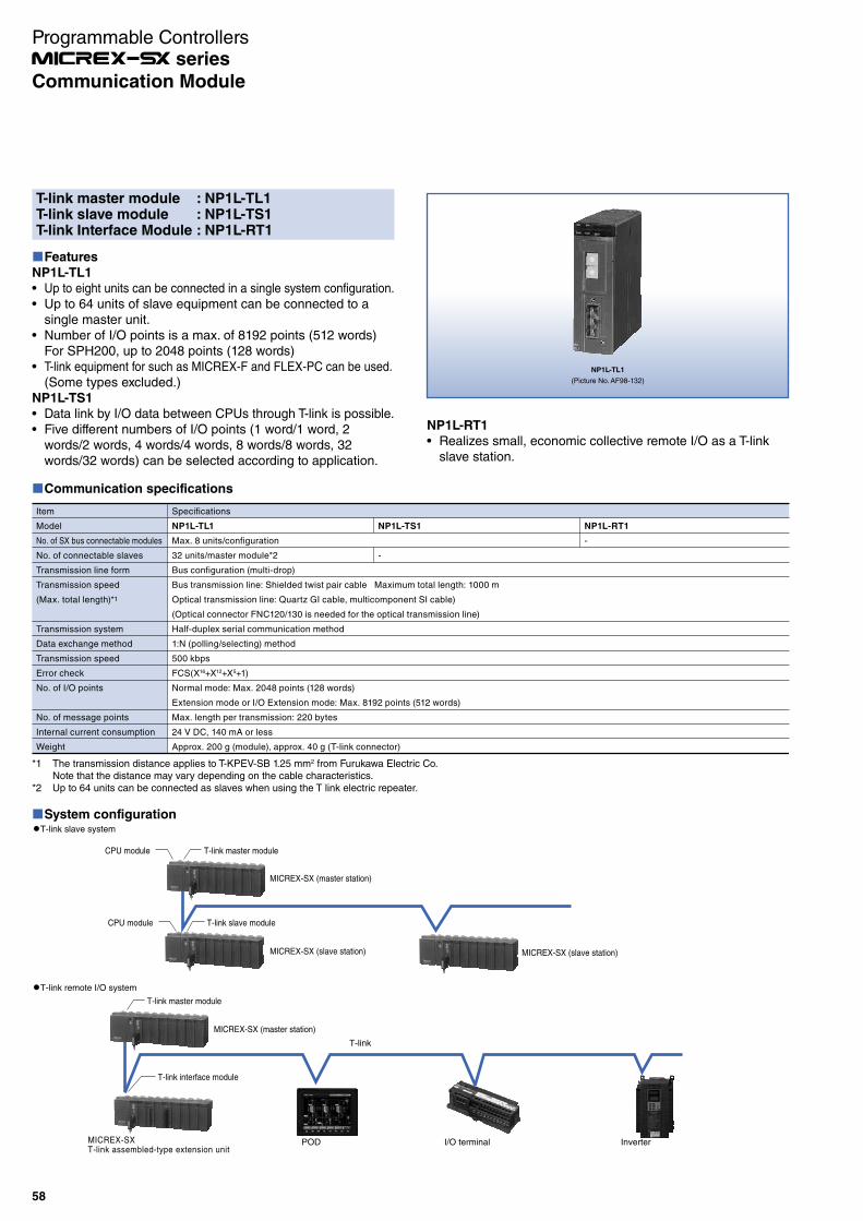
NP1L-TL1
(Picture No. AF98-132)
NP1L-RT1
Realizes small, economic collective remote I/O as a T-link slave station.
System configuration
MICREX-SXT-link assembled-type extension unit
POD I/O terminal Inverter
T-link
T-link slave system
T-link remote I/O system
CPU module T-link master module
CPU module T-link slave module
T-link master module
T-link interface module
MICREX-SX (master station)
MICREX-SX (slave station)MICREX-SX (slave station)
MICREX-SX (master station)
T-link master module : NP1L-TL1T-link slave module : NP1L-TS1T-link Interface Module : NP1L-RT1
Features
NP1L-TL1
Up to eight units can be connected in a single system configuration.Up to 64 units of slave equipment can be connected to a single master unit.Number of I/O points is a max. of 8192 points (512 words)For SPH200, up to 2048 points (128 words)T-link equipment for such as MICREX-F and FLEX-PC can be used.(Some types excluded.)
NP1L-TS1
Data link by I/O data between CPUs through T-link is possible.Five different numbers of I/O points (1 word/1 word, 2 words/2 words, 4 words/4 words, 8 words/8 words, 32 words/32 words) can be selected according to application.
*1 The transmission distance applies to T-KPEV-SB 1.25 mm2 from Furukawa Electric Co.Note that the distance may vary depending on the cable characteristics.
*2 Up to 64 units can be connected as slaves when using the T link electric repeater.
Communication specifications
Item
Model
No. of SX bus connectable modules
No. of connectable slaves
Transmission line form
Transmission speed
(Max. total length)*1
Transmission system
Data exchange method
Transmission speed
Error check
No. of I/O points
No. of message points
Internal current consumption
Weight
Specifications
NP1L-TL1
Max. 8 units/configuration
32 units/master module*2
Bus configuration (multi-drop)
Bus transmission line: Shielded twist pair cable Maximum total length: 1000 m
Optical transmission line: Quartz GI cable, multicomponent SI cable)
(Optical connector FNC120/130 is needed for the optical transmission line)
Half-duplex serial communication method
1:N (polling/selecting) method
500 kbps
FCS(X16+X12+X5+1)
Normal mode: Max. 2048 points (128 words)
Extension mode or I/O Extension mode: Max. 8192 points (512 words)
Max. length per transmission: 220 bytes
24 V DC, 140 mA or less
Approx. 200 g (module), approx. 40 g (T-link connector)
NP1L-RT1
-
NP1L-TS1
-
58
Communication Module
Programmable Controllers series

PROFIBUS-DP Master Module : NP1L-PD1PROFIBUS-DP Slave Module : NP1L-PS1PROFIBUS-DP Interface Module : NP1L-RP1
Features
NP1L-PD1
Open systemDiverse slave products of PROFIBUS-DP can be connected. As for the DP slave, the compatibility authenticated by the PROFIBUS association has been confirmed. (The number of vendors exceeds 300.)
Flexible system configurationIn addition to the basic configuration consisting of one DP master and multiple DP slaves, combinations with multiple DP masters and multiple DP slaves are possible, making it easier to distribute master functions.Max. number of unit connections (including master stations) is 126. With 33 units or more, repeaters are required.
Transmission speedCan be selected from nine options: 9.6/19.2/93.75/187.5/500/1500/ 3000/6000/12000 kbps. (The upper limit depends on the type of the DP slave.)
NP1L-PD1
(Picture No. KD02-038A)
NP1L-PS1/RP1
(Picture No. KD03-023)
NP1L-PR1
This communication module realizes collective remote I/O as a PROFIBUS-DP slave station.
NP1L-PS1
I/O data link through the PROFIBUS-DP is possible between CPUs.
A max. of 128 words can be controlled as an input/output
total of I/O points.
Please purchase from:
HMS INDUSTRIAL NETWORKS +81-45-478-5340
Configurator Software: KONF-PDP
Used to download the system configuration information to the PROFIBUS-DP master module. Required to update the initial setup or system configuration.
System configuration
PROFIBUS-DP
PROFIBUS-DP-basedservo system from other manufacturers
InverterPOD PROFIBUS-DP-basedactuator from
other manufacturers
PROFIBUS-DP-basedsensor from
other manufacturers
MICREX-SX(slave station)
PROFIBUS-DPassembled-typeexpansion unit
PROFIBUS-DP master module
PROFIBUS-DPslave module
PROFIBUS-DPinterface module
MICREX-SX (master station)
Performance specifications
Item
Model
No. of SX bus connectable modules
Applicable standards
Communication function
No. of slave station connections
Station No. (station address) setup range
Transmission line form
Communication standard
Data exchange method
Transmission speed
Transmission distance
Cable
No. of I/O points
Internal current consumption
Weight
Specifications
NP1L-PD1
Max. 8 units/configuration
IEC 66158, EN 50170, DIN 19245
PROFIBUS-DP master (DPM1) function
Up to 32 units (up to 126 units with repeaters)
0 to 125
Bus configuration (multi-drop)
Applicable to EN 50170 and DIN 19245
1:N (polling/selecting) method
Nine options (set by configuration of the programming loader)
9.6, 19.2, 93.75, 187.5, 500, 1,500, 3,000, 6,000, 12,000 (kbps)
1,200 m at the transmission speed of 9.6 bps; 100 m at the transmission speed of 12 Mbps (See the table below.)
PROFIBUS-DP cable
(Shielded twist pair cable)
Normal mode: Max. 2048 points (128 words) *1
Extension mode or I/O extension mode: Max. 8160 points (510 words)
24 V DC, 200 mA or less
Approx. 250 g
NP1L-PS1
PROFIBUS-DP slave function
-
0 to 99
In total I/O: Max. 128 words
(Each I/O: Max. 122 words)
24 V DC, 150 mA or less
Approx. 180 g
NP1L-RP1
-
Baud rate (kbps) 9.6 19.2 93.75 187.5 500 1,500 3,000 6,000 12,000
Distance/segment 1,200 m 1,200 m 1,200 m 1,000 m 400 m 200 m 100 m 100 m 100 m
*1 SPH200 supports standard mode only.
59
Communication Module
Programmable Controllers series

NP1L-MN1
M-NET Communication Module: NP1L-MN1
Features
The module is available as a master or slave station by switching the station No.Up to seven child stations can be connected.A terminating resistor is built-in.
Specification
Item
Number of channels
Main functions
Transmission information
Transmission speed
Form of connection
Signal level
Communication method
Synchronization method
Communication speed
Transmission distance
Weight
Description
1 channel
Parent/child station
256
Normally connected with seven stations with 256 points: up to 100 ms per cycle
1:N (N: up to 7)
EIA standard: RS-422
Half-duplex system
Asynchronous (async)
19.2 kbps/57.6 kbps
Up to 100 m
Approx. 175 g (no connector)
System configuration
Master station
Slave station
M-NET
Instruments NC Equipment
60
Communication Module
Programmable Controllers series
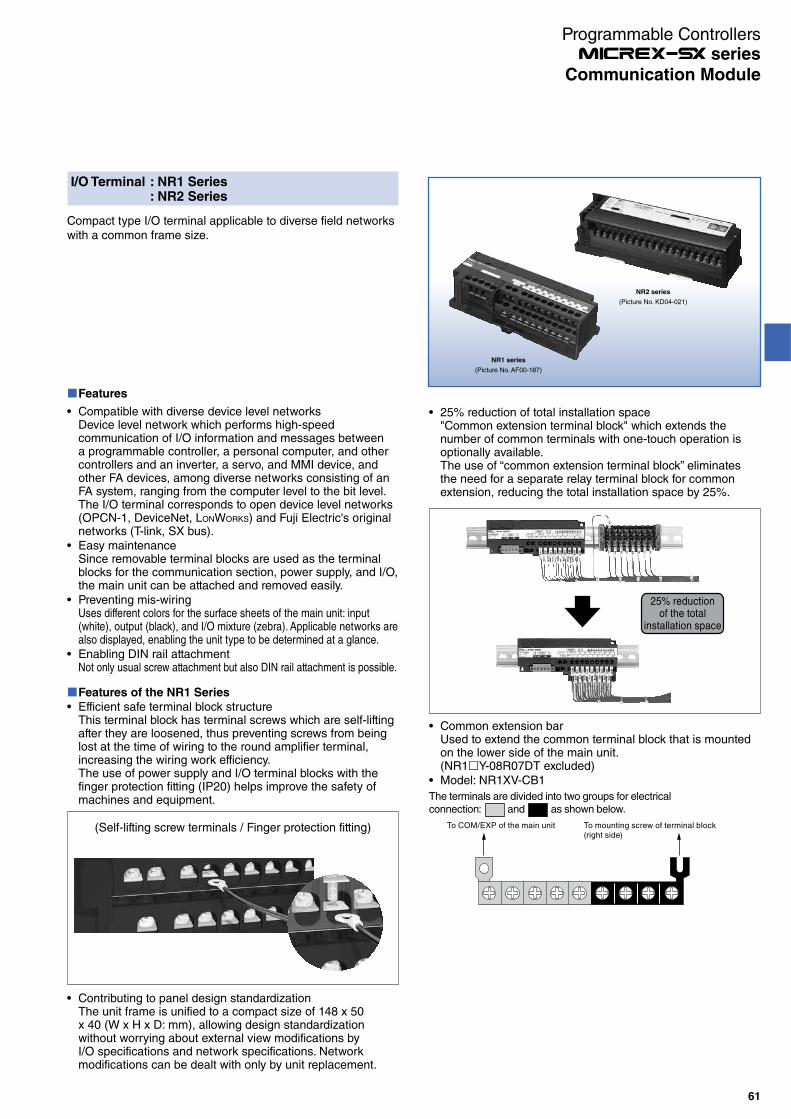
I/O Terminal : NR1 Series: NR2 Series
Compact type I/O terminal applicable to diverse field networks with a common frame size.
Features
Compatible with diverse device level networksDevice level network which performs high-speed communication of I/O information and messages between a programmable controller, a personal computer, and other controllers and an inverter, a servo, and MMI device, and other FA devices, among diverse networks consisting of an FA system, ranging from the computer level to the bit level.The I/O terminal corresponds to open device level networks (OPCN-1, DeviceNet, LONWORKS) and Fuji Electric's original networks (T-link, SX bus).Easy maintenanceSince removable terminal blocks are used as the terminal blocks for the communication section, power supply, and I/O, the main unit can be attached and removed easily.Preventing mis-wiringUses different colors for the surface sheets of the main unit: input (white), output (black), and I/O mixture (zebra). Applicable networks are also displayed, enabling the unit type to be determined at a glance.Enabling DIN rail attachmentNot only usual screw attachment but also DIN rail attachment is possible.
NR1 series
(Picture No. AF00-187)
NR2 series
(Picture No. KD04-021)
Features of the NR1 Series
Efficient safe terminal block structureThis terminal block has terminal screws which are self-lifting after they are loosened, thus preventing screws from being lost at the time of wiring to the round amplifier terminal, increasing the wiring work efficiency.The use of power supply and I/O terminal blocks with the finger protection fitting (IP20) helps improve the safety of machines and equipment.
(Self-lifting screw terminals / Finger protection fitting)
Contributing to panel design standardizationThe unit frame is unified to a compact size of 148 x 50 x 40 (W x H x D: mm), allowing design standardization without worrying about external view modifications by I/O specifications and network specifications. Network modifications can be dealt with only by unit replacement.
25% reduction of total installation space"Common extension terminal block" which extends the number of common terminals with one-touch operation is optionally available.The use of “common extension terminal block” eliminates the need for a separate relay terminal block for common extension, reducing the total installation space by 25%.
Common extension barUsed to extend the common terminal block that is mounted on the lower side of the main unit.(NR1 Y-08R07DT excluded)Model: NR1XV-CB1
To COM/EXP of the main unit To mounting screw of terminal block (right side)
The terminals are divided into two groups for electrical connection: and as shown below.
25% reductionof the total
installation space
61
Communication Module
Programmable Controllers series
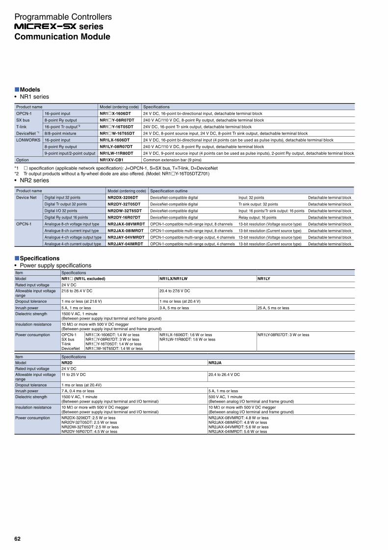
Models
NR1 series
Product name
OPCN-1
SX bus
T-link
DeviceNet *1
LONWORKS
Option
16-point input
8-point Ry output
16-point Tr output*2
8/8-point mixture
16-point input
8-point Ry output
9-point input/2-point output
Model (ordering code)
NR1 X-1606DT
NR1 Y-08R07DT
NR1 Y-16T05DT
NR1 W-16T65DT
NR1LX-1606DT
NR1LY-08R07DT
NR1LW-11R80DT
NR1XV-CB1
Specifications
24 V DC, 16-point bi-directional input, detachable terminal block
240 V AC/110 V DC, 8-point Ry output, detachable terminal block
24V DC, 16-point Tr sink output, detachable terminal block
24 V DC, 8-point source input, 24 V DC, 8-point Tr sink output, detachable terminal block
24 V DC, 16-point bi-directional input (4 points can be used as pulse inputs), detachable terminal block
240 V AC/110 V DC, 8-point Ry output, detachable terminal block
24 V DC, 9-point source input (4 points can be used as pulse inputs), 2-point Ry output, detachable terminal block
Common extension bar (9 pins)
*1 specification (applicable network specification): J=OPCN-1, S=SX bus, T=T-link, D=DeviceNet*2 Tr output products without a fly-wheel diode are also offered. (Model: NR1 Y-16T05DTZ701)
NR2 series
Digital input 32 points
Digital Tr output 32 points
Digital I/O 32 points
Digital Ry output 16 points
Analogue 8-ch voltage input type
Analogue 8-ch current input type
Analogue 4-ch voltage output type
Analogue 4-ch current output type
Model (ordering code)
NR2DX-3206DT
NR2DY-32T05DT
NR2DW-32T65DT
NR2DY-16R07DT
NR2JAX-08VMRDT
NR2JAX-08IMRDT
NR2JAY-04VMRDT
NR2JAY-04IMRDT
Specification outline
DeviceNet-compatible digital
DeviceNet-compatible digital
DeviceNet-compatible digital
DeviceNet-compatible digital
OPCN-1-compatible multi-range input, 8 channels
OPCN-1-compatible multi-range input, 8 channels
OPCN-1-compatible multi-range output, 4 channels
OPCN-1-compatible multi-range output, 4 channels
Input: 32 points
Tr sink output: 32 points
Input: 16 points/Tr sink output: 16 points
Relay output: 16 points
13-bit resolution (Voltage source type)
13-bit resolution (Current source type)
13-bit resolution (Voltage source type)
13-bit resolution (Current source type)
Detachable terminal block
Detachable terminal block
Detachable terminal block
Detachable terminal block
Detachable terminal block
Detachable terminal block
Detachable terminal block
Detachable terminal block
Product name
Device Net
OPCN-1
Specifications
Power supply specificationsItem Specifications
Model NR1 (NR1L excluded) NR1LX/NR1LW NR1LY
Rated input voltage 24 V DC
Allowable input voltage range
21.6 to 26.4 V DC 20.4 to 27.6 V DC
Dropout tolerance 1 ms or less (at 21.6 V) 1 ms or less (at 20.4 V)
Inrush power 5 A, 1 ms or less 3 A, 5 ms or less 25 A, 5 ms or less
Dielectric strength 1500 V AC, 1 minute(Between power supply input terminal and frame ground)
Insulation resistance 10 MΩ or more with 500 V DC megger(Between power supply input terminal and frame ground)
Power consumption OPCN-1SX busT-linkDeviceNet
NR1 X-1606DT: 1.4 W or lessNR1 Y-08R07DT: 3 W or lessNR1 Y-16T05DT: 1.4 W or lessNR1 W-16T65DT: 1.4 W or less
NR1LX-1606DT: 1.6 W or lessNR1LW-11R80DT: 1.6 W or less
NR1LY-08R07DT: 3 W or less
Item Specifications
Model NR2D NR2JA
Rated input voltage 24 V DC
Allowable input voltage range
11 to 25 V DC 20.4 to 26.4 V DC
Dropout tolerance 1 ms or less (at 20.4V)
Inrush power 7 A, 0.4 ms or less 5 A, 1 ms or less
Dielectric strength 1500 V AC, 1 minute(Between power supply input terminal and I/O terminal)
500 V AC, 1 minute(Between analog I/O terminal and frame ground)
Insulation resistance 10 MΩ or more with 500 V DC megger(Between power supply input terminal and I/O terminal)
10 MΩ or more with 500 V DC megger(Between analog I/O terminal and frame ground)
Power consumption NR2DX-3206DT: 2.5 W or lessNR2DY-32T05DT: 2.5 W or lessNR2DW-32T65DT: 2.5 W or lessNR2DY-16R07DT: 4.5 W or less
NR2JAX-08VMRDT: 4.8 W or lessNR2JAX-08IMRDT: 4.8 W or lessNR2JAX-04VMRDT: 5.6 W or lessNR2JAX-04IMRDT: 5.6 W or less
62
Communication Module
Programmable Controllers series
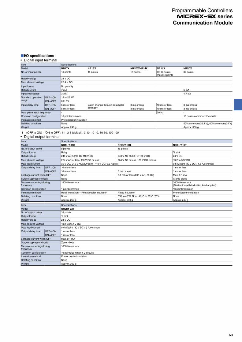
I/O specifications
Digital input terminalItem Specifications
Model NR1TX NR1SX NR1DX/NR1JX NR1LX NR2DX
No. of input points 16 points 16 points 16 points Di: 12 points Pulse: 4 points
32 points
Rated voltage 24 V DC
Max. allowed voltage 26.4 V DC
Input format No polarity
Rated current 7 mA 5 mA
Input impedance 3.3 kΩ 4.7 kΩ
Standard operation range
OFF ON 15 to 26.4V
ON OFF 0 to 5V
Input delay time OFF ON 5 ms or less Batch change through parameter settings*1
3 ms or less 10 ms or less 3 ms or less
ON OFF 5 ms or less 3 ms or less 10 ms or less 3 ms or less
Max. pulse input frequency - 20 Hz -
Common configuration 16 points/common 16 points/common x 2 circuits
Insulation method Photocoupler insulation
Delating condition None 50%/common (26.4 V), 60%/common (24 V)
Weight Approx. 240 g Approx. 300 g
*1 (OFF to ON) - (ON to OFF): 1-1, 3-3 (default), 3-10, 10-10, 30-30, 100-100
Digital output terminalItem Specifications
Model NR1 Y-08R NR2DY-16R NR1 Y-16T
No. of output points 8 points 16 points
Output format Relay Tr sink
Rated voltage 240 V AC 50/60 Hz 110 V DC 240 V AC 50/60 Hz 120 V DC 24 V DC
Max. allowed voltage 264 V AC or less, 110 V DC or less 264 V AC or less, 120 V DC or less 19.2 to 30V DC
Max. load current 30 V DC/ 240 V AC: 2 A/point 110 V DC: 0.2 A/point 0.6 A/point (30 V DC), 4.8 A/common
Output delay time OFF ON 10 ms or less 1 ms or less
ON OFF 10 ms or less 5 ms or less 1 ms or less
Leakage current when OFF None 0.1 mA or less (200 V AC, 60 Hz) Max. 0.1 mA
Surge suppresser circuit None Clamp diode
Maximum opening/closing frequency
1800 times/hour 3600 times/hour (Restriction with induction load applied)
Common configuration 1 point/common 16 points/common
Insulation method Relay insulation + Photocoupler insulation Relay insulation Photocoupler insulation
Delating condition None 0°C to 40°C: Non 40°C to 55°C: 75% None
Weight Approx. 250 g Approx. 340 g Approx. 240 g
Item Specifications
Model NR2DY-32T
No. of output points 32 points
Output format Tr sink
Rated voltage 24 V DC
Max. allowed voltage 19.2 to 26.4 V DC
Max. load current 0.5 A/point (30 V DC), 3 A/common
Output delay time OFF ON 1 ms or less
ON OFF 1 ms or less
Leakage current when OFF Max. 0.1 mA
Surge suppresser circuit Zener diode
Maximum opening/closing frequency
1800 times/hour
Common configuration 16 points/common x 2 circuits
Insulation method Photocoupler insulation
Delating condition None
Weight Approx. 300 g
63
Communication Module
Programmable Controllers series
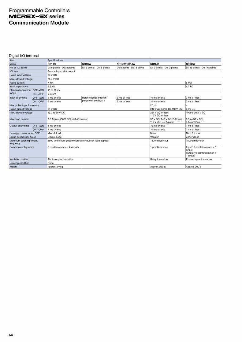
Digital I/O terminalItem Specifications
Model NR1TW NR1SW NR1DW/NR1JW NR1LW NR2DW
No. of I/O points Di: 8 points Do: 8 points Di: 8 points Do: 8 points Di: 8 points Do: 8 points Di: 9 points Do: 2 points Di: 16 points Do: 16 points
I/O form Source input, sink output
Rated input voltage 24 V DC
Max. allowed voltage 26.4 V DC
Rated current 7 mA 5 mA
Input impedance 3.3 kΩ 4.7 kΩ
Standard operation range
OFF ON 15 to 26.4V
ON OFF 0 to 5 V
Input delay time OFF ON 5 ms or less Batch change through parameter settings*1
3 ms or less 10 ms or less 3 ms or less
ON OFF 5 ms or less 3 ms or less 10 ms or less 3 ms or less
Max. pulse input frequency - 20 Hz -
Rated output voltage 24 V DC 240 V AC 50/60 Hz 110 V DC 24 V DC
Max. allowed voltage 19.2 to 30 V DC 264 V AC or less110 V DC or less
19.2 to 26.4 V DC
Max. load current 0.6 A/point (30 V DC), 4.8 A/common 30 V DC/ 240 V AC: 2 A/point110 V DC: 0.2 A/point
0.5 A (30 V DC),3 A/common
Output delay time OFF ON 1 ms or less 10 ms or less 1 ms or less
ON OFF 1 ms or less 10 ms or less 1 ms or less
Leakage current when OFF Max. 0.1 mA None Max. 0.1 mA
Surge suppresser circuit Clamp diode Varistor Zener diode
Maximum opening/closing frequency
3600 times/hour (Restriction with induction load applied) 1800 times/hour 1800 times/hour
Common configuration 8 points/common x 2 circuits 1 point/common Input 16 points/common x 1 circuitOutput 16 points/common x 1 circuit
Insulation method Photocoupler insulation Relay insulation Photocoupler insulation
Delating condition None
Weight Approx. 240 g Approx. 260 g Approx. 300 g
64
Communication Module
Programmable Controllers series

Analog I/O specificationAnalog voltage input type/ current input type
Item
Model
No. of input points
Analog input range
Input impedance
Max. allowed input
Input filter
Max. resolution
Digital value (INT type)
Measurement accuracy
Sampling interval
Response time
No. of occupied words
Insulation method
Dielectric strength
Insulation resistance
External connections
Weight
Specifications
NR2JAX-08VMRDT
8 points
0 to 5 V
1 MΩ
±15 V
Approx. 100 μs or less (Hardware: Primary delay time constant)
1.25 mV
0 to 4000
±0.1% of F.S.R (Ta = 23°C±5°C)
±0.3% of F.S.R (Ta = 0 to 55°C)
4 ms or less/8 points
4 ms or less/8 points + transmission periods (ms)
Input: 8 words
Between analog input terminals and FG: Isolation
Between analog input terminals and communication terminals: Isolation
Between analog input terminals and channels: Not isolation
500 V AC, 1 minute, between analog input terminals and FG (short-circuit current: 5 mA)
10 MΩ with 500 V DC megger, between analog input terminals and FG
External power supply, analog input connection: Detachable screw terminal block (M3x 38 poles)
Communication connection: Detachable screw terminal block (M3 x 3 poles)
Approx. 340 g
1 to 5 V
1.25 mV
0 to 10 V
1.25 mV
0 to 8000
-10 to +10 V
1.25 mV
-8000 to 8000
NR2JAX-08IMRDT
8 points
±20 mA
250 Ω
±30 mA
Approx. 100 μs or less (Hardware: Primary delay time constant)
2.5 μA
±8000
±0.1% of F.S.R (Ta = 23°C±5°C)
±0.4% of F.S.R (Ta = 0 to 55°C)
4 ms/4 points
4 ms or less/8 points + transmission periods (ms)
Input: 8 words
Between analog input terminals and FG: Isolation
Between analog input terminals and communication terminals: Isolation
Between analog input terminals and channels: Not isolation
500 V AC, 1 minute, between analog input terminals and FG (short-circuit current: 5 mA)
10 MΩ with 500 V DC megger, between analog input terminals and FG
External power supply, analog input connection: Detachable screw terminal block (M3x 38 poles)
Communication connection: Detachable screw terminal block (M3 x 3 poles)
Approx. 340 g
0 to 20 mA
0 to 8000
4 to 20 mA
Analog voltage output type/ current output type
Item
Model
No. of input points
Analog output range
Load impedance
Max. resolution
Digital value (INT type)
Measurement accuracy
Sampling interval
Response time
Load short protection
High-frequency noise (100 kHz or more)
Output ripple
No. of occupied words
Insulation method
Dielectric strength
Insulation resistance
External connections
Weight
Specifications
NR2JAY-04VMRDT
4 points
0 to + 5 V
1 kΩ or more
1.25 mV
0 to 4000
±0.1% of F.S.R (Ta = 23°C±5°C)
±0.3% of F.S.R (Ta = 0 to 55°C)
2 ms/4 points
2 ms or less/4 points + transmission periods (ms)
Provided
150 mVp-p or less
50 mVp-p or less
Output: 4 words
Between analog input terminals and FG: Isolation
Between analog input terminals and communication terminals: Isolation
Between analog input terminals and channels: Not isolation
500 V AC, 1 minute, between analog input terminals and FG (short-circuit current: 5 mA)
10 MΩ with 500 V DC megger, between analog input terminals and FG
External power supply, analog input connection: Detachable screw terminal block (M3) 38 poles
Communication connection: Detachable screw terminal block (M3 x 3 poles)
Approx. 340 g
1 to + 5 V
1 kΩ or more
1.25 mV
0 to + 10 V
2 kΩ or more
1.25 mV
0 to 8000
-10 to + 10 V
2 kΩ or more
1.25 mV
-8000 to 8000
NR2JAY-04IMRDT
4 points
0 to 20 mA
500 Ω or less
2.5 μA
0 to 8000
±0.2% of F.S.R (Ta = 23°C±5°C)
±0.4% of F.S.R (Ta = 0 to 55°C)
2 ms/4 points
2 ms or less/4 points + transmission periods (ms)
300 μAp-p or less
100 μAp-p or less
Output: 4 words
Between analog input terminals and FG: Isolation
Between analog input terminals and communication terminals: Isolation
Between analog input terminals and channels: Not isolation
500 V AC, 1 minute, between analog input terminals and FG (short-circuit current: 5 mA)
10 MΩ with 500 V DC megger, between analog input terminals and FG
External power supply, analog input connection: Detachable screw terminal block (M3) 38 poles
Communication connection: Detachable screw terminal block (M3 x 3 poles)
350 g
4 to 20 mA
Characteristic of the analog voltage/current input type
Converted value (INT)
8000(4000)
4000(2000)
Input value0
1 3 5 (V)20 (mA)
Converted value in ( ):1 to 5 V input
4 12-2000(-1000)
±10 V/±20 mA 0 to 5 V/0 to 10V
Converted value (INT)
8000
4000
-8000
Input value
0 5 1020
-1020
(V)(mA)
Converted value (INT)
Input value
0 52.5
105
(V)(V)4
1600
8000(4000)
4000(2000)
Converted value in ( ):0 to 5 V input
1 to 5 V/4 to 20 mA
Characteristic of the analog voltage/current output type
-10 to 10 V 0 to 5 V/0 to 10V
Converted value (V)
10
5
-10
Input value
0 4000 8000-8000 (INT)
Converted value (V)
10(5)
5(2.5)
Input value
0 4000(2000)
8000(4000)
(INT)
In ( ):0 to 5 V output
0 to 20 mA
Converted value (V/mA)
20(5)
12(3)
Input value
0 4000(2000)
8000(4000)
(INT)
Converted value (mA)
20
Input value
8000 (INT)
In ( ):1 to 5 V output
4(1)
1 to 5 V/4 to 20 mA
65
Communication Module
Programmable Controllers series

*1 When the master module of MICREX-SX series is used*2 The max. number of the I/O terminal (for SX bus) connections are 10 units each in the inside and outside per base board.
Consumes the SX bus transmission power supply by 25 mA per I/O terminal.
Communication specifications
DeviceNet
Bus type (multi-drop, T-branching)
127 channels (2032 points)/master
(When configurator is not used)
125 kbps/500 m
250 Kbps/250 m
500 Kbps/100 m
(Changes with the switch)
64 nodes
—
DeviceNet cable
Specifications
OPCN-1
Bus type (multi-drop)
127 words (2032 points)/master
125 kbps/1 km
250 Kbps/800 m
500 kbps/480 m
1 Mbps/240 m
(Changes with the switch)
31 stations
EIA RS-485
Shielded twisted pair cable
8 points: 1 word, 16 points: 1 word, 32 points: 2 words, 8/8 (Mixture): 2 words, 16/16 (Mixture): 2 words, analog input: 8 words, analog output: 4 words, NR1SF-HP4DT: 40 words
SX bus
Bus type (ring)
512 words (8192 words)
25 Mbps/25 m
254 stations (including CPU module) *2
EIA RS-422
SX bus expansion cable
T-link
Bus type (multi-drop)
128 words (2048 points)/master
500 kbps/1 km
32 stations
Dedicated pulse transfer method
Shielded twisted pair cable
LONWORKS
Free topology (bus-type/star-type)
228 bytes
78 kbps/500 to 2700 m
64 units/segment
—
Twisted pair (1P-S)
Item
Transmission line format
Max. signal points
Transmission speed/distance
No. of connected stations
Electric characteristics
Transmission medium
Occupied word *1
*1 Please mount the terminating resistor with the accessory of the master module (2 pieces provided on the SX) if the I/O terminals for OPCN-1 or for T-link are a terminating station.(The I/O terminals have not been fitted with terminating resistors.)
System configuration
Product from other manufacturers
<MICREX-SX: SPH>
Other manufacture’s PLC
*1*1
66
Communication Module
Programmable Controllers series
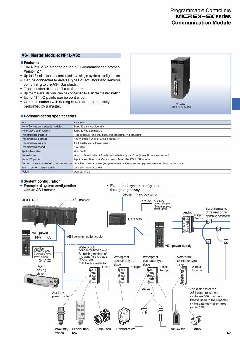
NP1L-AS2
(Picture No. AF00-196)
AS-i Master Module: NP1L-AS2
Features
The NP1L-AS2 is based on the AS-i communication protocol Version 2.1.Up to 12 units can be connected in a single-system configuration.Can be connected to diverse types of actuators and sensors conforming to the AS-i Standards.Transmission distance: Total of 100 mUp to 62 slave stations can be connected to a single master station.Up to 434 I/O points can be controlled.Communications with analog slaves are automatically performed by a master.
System configuration
Communication specifications
Item
No. of SX bus connectable modules
No. of slave connections
Transmission line form
Transmission distance
Transmission system
Transmission speed
Applicable cable
Refresh time
No. of I/O points
Current consumption of AS-i master section
Internal current consumption
Weight
Description
Max. 12 units/configuration
Max. 62 /master module
Tree-structure, line-structure, star-structure, ring-structure
100 m (Max. 300 m at using a repeater)
Half-duplex serial transmission
167 kbps
AS-i cable
Approx. 10 ms (when 62 units connected), approx. 5 ms (when 31 units connected)
Input points: Max. 248, Output points: Max. 186 (I/O: 21/21 words)
30 V DC, 100 mA or less (supplied from the AS-i power supply, and insulated from the SX bus.)
24 V DC, 100 mA or less
Approx. 180 g
AS-i
OUT3
IN2
IN1
OUT4
AS-i
24 V DC
AS-I power supply
AS-I power supply
Gate way
Auxiliarypower supply(General-purposepower supply)
Auxiliarypower supply(General-purposepower supply)
Digitalpickingslave
Waterproofconnector-type slave
AS-i communication cable
Waterproofconnector-typeslave
Waterproofconnector-typeslave
Waterproofconnector-typeslave
Blanching method of the used to the slave (T-blanch)* H-blanch possible too.
Blanching method of the used to the blanching connector
4-input 4-output
24 V DC
OPCN-1, T-link, DeviceNet
2-input2-output
2-input2-output
Analog2-input2-output
Proximityswitch
Pushbuttonbox
Pushbutton Control relay
Valve
Limit switch Lamp
Auxiliarypower cable
* The distance of the AS-i communication cable are 100 m or less.Please used to the repeater or the extender for or more (up to 300 m).
MICREX-SX AS-i master
Example of system configuration with an AS-i master
Example of system configuration through a gateway
67
Communication Module
Programmable Controllers series

NP1L-SL1
(Picture No. AF01-102)
S-LINK Master Module: NP1L-SL1
Features
Connected to the S-LINK (bit) level serial transmission provided by SUNX.128 points I/O control can be performed for each master station. There is no limitation to the number of master connections.
External 24 V DC power supply for S-LINK
Loop wiring is possible.
Unique station No. is set to each slave.
S-LINK master module
4-wire flat cable
T-branch connection is possible.
System configuration
Communication specifications
Item
No. of SX bus connectable modules
No. of slave connections
Transmission system
Synchronization method
Transmission method
Transmission speed
Transmission distance
Connection method
No. of I/O points
Applicable cable
Refresh time
S-LINK master section current consumption
Internal current consumption
Weight
Specifications
No limitation (within the limit of the max. number of SX bus connections of 8192 points)
No limitation
Bi-directional time-division multiplex transmission system
Bit synchronization, frame synchronization
2-wire protocol
28.5 kbps
Signal trunk line: Total length 200 m
Multi-drop connection
Up to 128 points
Cable from SUNX: 4-wire flat cable
32 points: 1.4 to 2.9 ms
64 points: 2.5 to 5.2 ms
96 points: 3.6 to 7.4 ms
128 points: 4.7 to 9.6 ms
24 V DC, 1.6 A or less (supplied from an external power supply. Insulated from the SX bus.)
Inside of module (supplied from the SX bus): 24 V DC, 80 mA or less, S-LINK communication section (supplied from an external power supply): 24 V DC, 1.6 A or less
Approx. 200 g
68
Communication Module
Programmable Controllers series

NP1L-RM1
(Picture No. No.KDD06-002)
Remote Terminal Master/Slave Module: NP1L-RM1
Features
Connectable to Fuji Electric’s RM20 and RM21 remote terminal series.Data can be transmitted up to 5 km between master/slave modules and remote terminals.The use of a signal converter makes it possible to use existing, unoccupied cables and trolley lines.
System configuration
Signal converter(RM20-WB)
Trolley wire
1:1 slave mode
1:N master mode
Signal converter(RM20-WA)
Communication specifications
Item
No. of SX bus connectable modules
No. of SX remote terminal link
Remote terminal
No. of connectable terminals/no. of signal points
No. of connectable remote
terminals
Remote
terminal
specification
External wire connections
External power supply (for communication)
Internal current consumption
Weight
Transmission system
Signal/Transmission speed
Transmission form
Signal transmission line
Transmission distance
Specifications
Max. 8 units/configuration
1 system
1:1 mode: Max. 64 words
1:N or N:N mode: Max. 128 units or 1024 points
1:1 mode: 1 slave/1 master
1:N mode: RM20/21 series terminal units
Time sharing cyclic multiplex transmission system
RZ signal/2400 baud (Built-in modulation/demodulation reference clock 7.2 K)
1:1 transmission (connection of between the SX master and slave station)
1:N or N:N transmission (Connects existing remote terminals. The NP1L-RM1 slave mode cannot be connected.)
Twisted pair cable (CPEV, KPEV), CVV, trolley wires
0.9: 2.0 km (Max. 128 remote stations)
1.2: 3.5 km (Max. 128 remote stations)
2 mm2: 5.0 km (Max. 64 remote stations)
2 to 5 km: Varies with the cable and connection configuration.
Terminal block 6 poles
(For transmission wire connections, for 24 V DC external power supply connections, for grounding etc.)
20 to 30 V DC, 3.6 VA (When 24 V DC: 0.15 A)
24 V DC, 140 mA or less
Approx. 210 g
69
Communication Module
Programmable Controllers series

70
Communication Module
Programmable Controllers series
USB Communication Module: NP1L-UC1
Features
Mounted on the base board to connect the CPU module (SPH2000/3000/3000D) with the programming support tool SX-Programmer.This module and the programming support tool are connected by a USB cable.The maximum number of these modules that can be connected in one configuration is 238.The programing support tool can be used while checking the actual state of IOs (actuator, control equipment) by mounting this module on each distributed base board.
System configuration
Communication specifications
Programming support tool SX-Programmer support version
The following version is required to use this module.Expert (D300win) V3 (Type: NP4H-SEDBV3) : V3.6.9 or later
Standard (Type: NP4H-SWN) : V3.0.14 or later
Item Specifications
No. of SX bus connectable modules Max. 238 units/configuration *1
USB interface No. of ports 1 port
Transmission speed 12 Mbps (USB1.1 Full Speed)
Transmission distance
3 m or less
Connection method USB-B connector
Max. number of units for loader communication simultaneously(Max. number of units for loader command communication simultaneously)
Up to 8 units *2
Combinable CPU SPH2000, SPH3000, SPH3000D single CPU system *3
Internal current consumption 24 V DC 150 mA or less
Weight Approx. 140 g
*1 Cannot be mounted on a remote I/O base board, such as T-link, OPCN-1, DeviceNet, and PROFIBUS-DP.*2 Includes the number of other pieces of equipment such as POD using the loader command communication.*3 Cannot be used in combination with SPH200/SPH300/SPH3000MM/SPH3000MG or in a multi-CPU system and CPU redundant system.
Max. of 238 modules can be installed
* Simultaneous loader communication
USB communication module
Max. of 8 units are available
USB communication module
USB communication module
USB communication module
SX-Programmer
SX-Programmer
SX-Programmer
NP1L-UC1
(Picture No. 0000-000)

Features
Using an SX bus optical link module/unit makes an SX bus transmission line optical and it possible to build a long-distance distributed system with the SX bus.NP1L-OL1/OL2
Mounted on the base board to transmit the SX bus signal as an optical signal.
NP2L-OE1
This unit connects between the SX bus cable and optical fiber cable to transmit the SX bus signal as an optical sign.
NP2L-OE1
(Picture No. AF00-198)
NP1L-OL1
(Picture No. AF00-195)
System configuration
CPU0"254" "1"
"3" "4" "5" "6" "7"
"8" "9" "10" "11" "12"
"15""14""13" "16" "17"
"2"
Hub configuration of SX buses
SX bus terminating plug
SX Bus Optical Link Module:(NP1L-OL1/OL2)
Optical fiber cable
Optical fiber cable
Optical fiber cable
SX bus terminating plug
SX bus terminating plug
SX bus extension cable
24 V DC
SX station No. 18
PODServo amplifier, etc.
SX bus extension cable
SX Bus Optical Converter Unit:NP2L-OE1
SX Bus Optical Link Module : NP1L-OL1/OL2SX Bus Optical Converter Unit : NP2L-OE1
*1 The minimum bending radius may depend on the type of optical fiber cable used.The transmission distance above is achieved at 25°C. The transmission distance is shorter at lower temperatures. For details, contact the optical fiber manufacturer.
*2 As an external power supply, use a switching power supply (conforming to the UL standard) with "reinforced insulation" of 24 V DC 1 A or more for each unit.*3 When 24 V DC is directly applied, the rush current is 50 Ao-p, 70 µs (reference value). This value depends on power conditions.
Recommended cables and tools (For PCF)· Optical fiber: HC-20/07 made by Sumitomo Electric Industries (type: H-PCF)
HG-20/08 (H-PCF type) made by Sumitomo Electric Industries (discontinued product)· Optical connector: CF-2071 made by Sumitomo Electric Industries· Crimp tool: CAK-0057 made by Sumitomo Electric Industries
Transmission specifications
Item
Model
No. of connectable modules
Optical fiber Type
Core/Clad diameter
Min. bending radius *1
Optical connector
Transmission distance *1
Internal current consumption
Power terminal Rated input voltage
(External power supply) Inrush current
*2
Weight
Specifications
NP1L-OL1
Max. 64 units/configuration (total No. of NP1L-OL1, NP1L-OL2 and NP2L-OE1)
PCF (Polymer Clad Fiber)
200 μm/230 μm
50 mm
Type: F07
HC-20/07 made by Sumitomo Electric Industries:
400 m max. between stations (total extension: 12.8 km)
HG-20/08 made by Sumitomo Electric Industries (discontinued product):
800 m max. between stations (total extension: 25.6 km)
24 V DC, 54 mA or less
—
—
Approx. 135 g
NP1L-OL2
Quartz glass fiber, GI type
50/125 μm
SC connector
2 km max. between stations (total extension: 64 km)
24 V DC, 30 mA or less
NP2L-OE1
PCF (Polymer Clad Fiber)
200 μm/230 μm
Type: F07
HC-20/07 made by Sumitomo Electric Industries:
400 m max. between stations (total extension: 12.8 km)
HG-20/08 made by Sumitomo Electric Industries (discontinued product):
800 m max. between stations (total extension: 25.6 km)
DC 24 V, 70 mA or less
24 V DC (DC22.8 ~ 26.4 V)
165 mA or less: When a switching power supply is used *3
50 Ao-p-70 µs: When 24 V DC is directly turned ON
Approx. 155 g
71
Communication Module
Programmable Controllers series
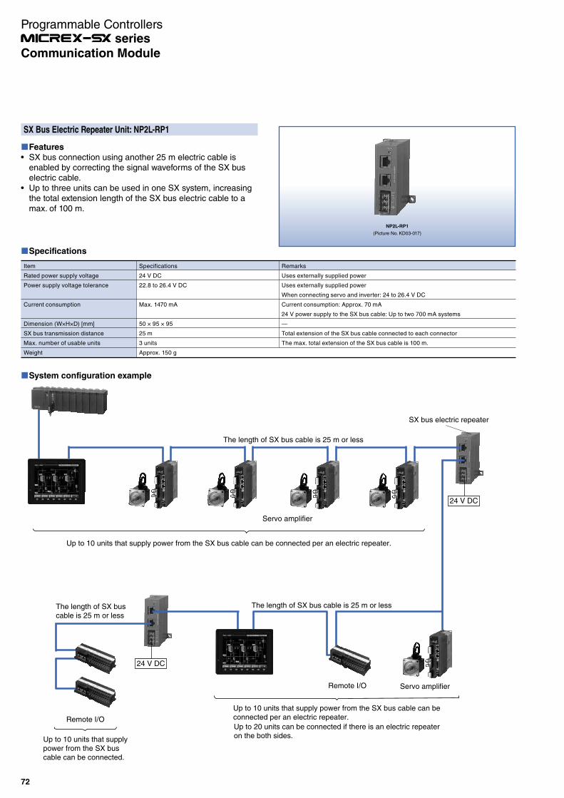
SX Bus Electric Repeater Unit: NP2L-RP1
Features
SX bus connection using another 25 m electric cable is enabled by correcting the signal waveforms of the SX bus electric cable.Up to three units can be used in one SX system, increasing the total extension length of the SX bus electric cable to a max. of 100 m.
NP2L-RP1
(Picture No. KD03-017)
System configuration example
The length of SX bus cable is 25 m or less
SX bus electric repeater
The length of SX bus cable is 25 m or lessThe length of SX buscable is 25 m or less
Up to 10 units that supply power from the SX bus cable can be connected per an electric repeater.
Up to 10 units that supplypower from the SX buscable can be connected.
Up to 10 units that supply power from the SX bus cable can beconnected per an electric repeater.
Up to 20 units can be connected if there is an electric repeateron the both sides.
Servo amplifier
Servo amplifierRemote I/O
Remote I/O
24 V DC
24 V DC
Specifications
Item
Rated power supply voltage
Power supply voltage tolerance
Current consumption
Dimension (W×H×D) [mm]
SX bus transmission distance
Max. number of usable units
Weight
Specifications
24 V DC
22.8 to 26.4 V DC
Max. 1470 mA
50 × 95 × 95
25 m
3 units
Approx. 150 g
Remarks
Uses externally supplied power
Uses externally supplied power
When connecting servo and inverter: 24 to 26.4 V DC
Current consumption: Approx. 70 mA
24 V power supply to the SX bus cable: Up to two 700 mA systems
—
Total extension of the SX bus cable connected to each connector
The max. total extension of the SX bus cable is 100 m.
72
Communication Module
Programmable Controllers series

NP2L-BH1
(Picture No. KDD11-001)
SX bus Duplication Unit: NP2L-BH1
Features
It is a unit to duplicate the SX bus cable from the base board.It is installed on the left side of the base board (adjacent to the SX bus connector of the base board) to physically separate the SX bus into 2 systems.The duplicated SX bus which allows the continued bus communication even when a line disconnection can be applicable to ships, power plants and vehicle systems that require high reliability.
Redundantsection
Redundantsection
SX bus connection of normal base board section SX bus connection for this unit connection
SpecificationsItem Specifications
Communication method SX bus communication (conforming to the SX bus transmission specifications)
Number of systems 2 systems of IN and OUT
Transmission speed 25 Mbps (conforming to the SX bus transmission specifications)
Interface connection shape SX bus extension connector (modular jack)
No. of connectable modules Max. 10 units
Connection distance Max. of 25 m distance between units, total length of 100 m
Power supply Unnecessary external power supply (24 V SX bus cable used)
Station number setting function
Available (using the station address setting rotary switch on the unit)
Installation method Independent type (no slots on the base board occupied)
Occupied number of I/O points
Input: 16 points(They are used for the status area and have no actual input function.)
Internal current consumption
24 V DC, 120 mA or less
Pick-up power source Operated by 24 V DC from the SX bus cable.
Weight Approx. 500g
Duplication operation
Switch operationWhen a broken wire is detected, the path is switched to another SX bus cable.
Wire break
Path switch
Bypass functionWhen the SX bus signals on both paths are stopped, the SX bus signals are looped back and the bypass connection is established in the duplication unit. (The SX bus disconnection is prevented.)
Wire break
Since the bypass connection is established,
"SX bus abnormality" does not occur resulting
from the SX bus disconnection.
System configuration example
Unused connectors are released.
(Automatically bypassed in the unit)
Unused connectors are released.
(Automatically bypassed in the unit)
Cable length between
base boards:
= Max. 25 m
OUT
IN
OUT
IN
73
Communication Module
Programmable Controllers series
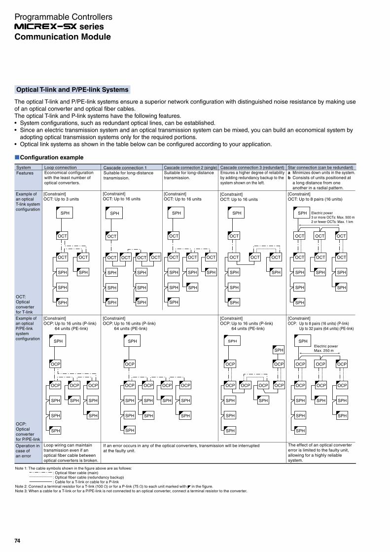
Configuration example
Note 1: The cable symbols shown in the figure above are as follows:: Optical fiber cable (main): Optical fiber cable (redundancy backup): Cable for a T-link or cable for a P-link
Note 2: Connect a terminal resistor for a T-link (100 Ω) or for a P-link (75 Ω) to each unit marked with in the figure.Note 3: When a cable for a T-link or for a P/PE-link is not connected to an optical converter, connect a terminal resistor to the converter.
System Loop connectionEconomical configurationwith the least number ofoptical converters.
Cascade connection 2 (single)Suitable for long-distancetransmission.
Cascade connection 3 (redundant)Ensures a higher degree of reliabilityby adding redundancy backup to thesystem shown on the left.
Star connection (can be redundant)a Minimizes down units in the system.b Consists of units positioned at
a long distance from oneanother in a radial pattern.
OCT:Opticalconverterfor T-link
OCP:Opticalconverterfor P/PE-link
Cascade connection 1Suitable for long-distancetransmission.
[Constraint]OCT: Up to 3 units
Loop wiring can maintaintransmission even if an optical fiber cable betweenoptical converters is broken.
If an error occurs in any of the optical converters, transmission will be interrupted at the faulty unit.
[Constraint]OCT: Up to 16 units
[Constraint]OCT: Up to 16 units
[Constraint]OCT: Up to 16 units
[Constraint]OCP: Up to 16 units (P-link)
64 units (PE-link)
[Constraint]OCP: Up to 8 pairs (16 units) (P-link)
Up to 32 pairs (64 units) (PE-link)
[Constraint]OCP: Up to 16 units (P-link)
64 units (PE-link)
[Constraint]OCP: Up to 16 units (P-link)
64 units (PE-link)
[Constraint]OCT: Up to 8 pairs (16 units)
The effect of an optical convertererror is limited to the faulty unit,allowing for a highly reliablesystem.
Operation incase ofan error
Example ofan opticalT-link systemconfiguration
Example ofan opticalP/PE-linksystemconfiguration
Features
SPH
OCT
OCT
SPH
OCT
SPH
SPH
SPH
SPH
OCT
OCT
SPH
SPH
OCT
SPH
OCT
SPH
SPH SPH
SPH
OCP
OCP
SPH
OCP
SPH
SPH
OCP
SPH
SPH
SPH
SPH
OCP
OCP
SPH
SPH
OCP
SPH
OCP
SPH
OCP
SPH
SPH SPH SPH
SPH
OCT
OCT
SPH
OCT OCT
SPH
SPH
SPH
SPH
OCP OCP
SPH
OCP
SPH
OCP OCPOCP
SPH
SPH
SPH
SPH
OCT OCT OCT
OCT
SPH
OCT OCT
SPH
SPH
SPH
SPH
SPH
Electric power3 or more OCTs: Max. 500 m2 or fewer OCTs: Max. 1 km
SPH
OCP OCP OCP
OCP
SPH
OCP OCP
SPH
SPH
SPH
SPH
SPH
Electric powerMax. 250 m
SPH
OCT
OCT
SPH
SPH
OCT OCT
SPH
SPH
SPH
SPH
OCT
Optical T-link and P/PE-link Systems
The optical T-link and P/PE-link systems ensure a superior network configuration with distinguished noise resistance by making use of an optical converter and optical fiber cables.The optical T-link and P-link systems have the following features.
System configurations, such as redundant optical lines, can be established.Since an electric transmission system and an optical transmission system can be mixed, you can build an economical system by adopting optical transmission systems only for the required portions.Optical link systems as shown in the table below can be configured according to your application.
74
Communication Module
Programmable Controllers series
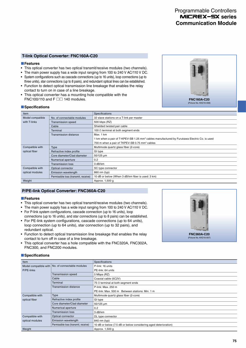
T-link Optical Converter: FNC160A-C20
Features
This optical converter has two optical transmit/receive modules (two channels).The main power supply has a wide input ranging from 100 to 240 V AC/110 V DC.System configurations such as cascade connections (up to 16 units), loop connections (up to three units), star connections (up to 8 pairs), and redundant optical lines can be established.Function to detect optical transmission line breakage that enables the relay contact to turn on in case of a line breakage. This optical converter has a mounting hole compatible with the FNC100/110 and F 140 modules.
Specifications
No. of connectable modules
Transmission speed
Cable
Terminal
Transmission distance
Type
Refractive index profile
Core diameter/Clad diameter
Numerical aperture
Transmission loss
Optical connector
Emission wavelength
Permissible loss (transmit, receive)
Item
Model compatible
with T-links
Compatible with
optical fiber
Compatible with
optical modules
Weight
Specifications
32 slave stations on a T-link per master
500 kbps (RZ)
Shielded twisted pair cable
100 Ω terminal at both segment ends
Max. 1 km
1 km when a pair of T-KPEV-SB 1.25 mm2 cables manufactured by Furukawa Electric Co. is used
700 m when a pair of TKPEV-SB 0.75 mm2 cables
Multimode quartz glass fiber (2-core)
GI type
50/125 μm
0.2
3 dB/km
SC type connector
860 nm (typ)
10 dB or below (When 3 dB/km fiber is used: 3 km)
Approx. 1,500 g
FNC160A-C20(Picture No. KKD10-008)
P/PE-link Optical Converter: FNC360A-C20
Features
This optical converter has two optical transmit/receive modules (two channels).The main power supply has a wide input ranging from 100 to 240 V AC/110 V DC.For P-link system configurations, cascade connection (up to 16 units), loop connections (up to 16 units), and star connections (up to 8 pairs) can be established.For PE-link system configurations, cascade connections (up to 64 units), loop connection (up to 64 units), star connection (up to 32 pairs), and redundant optical.Function to detect optical transmission line breakage that enables the relay contact to turn off in case of a line breakage. This optical converter has a hole compatible with the FNC320A, FNC302A, FNC300, and FNC200 modules.
Specifications
Item
Model compatible with
P/PE-links
Compatible with
optical fiber
Compatible with
optical modules
Weight
No. of connectable modules
Transmission speed
Cable
Terminal
Transmission distance
Type
Refractive index profile
Core diameter/Clad diameter
Numerical aperture
Transmission loss
Optical connector
Emission wavelength
Permissible loss (transmit, receive)
Specifications
P-link: 16 units
PE-link: 64 units
5 Mbps (RZ)
Coaxial cable (5C2V)
75 Ω terminal at both segment ends
P-link: Max. 250 m
PE-link: Max. 500 m Between stations: Min. 1 m
Multimode quartz glass fiber (2-core)
GI type
50/125 µm
0.2
3 dB/km
DL type connector
840 nm (typ)
10 dB or below (7.5 dB or below considering aged deterioration)
Approx. 1,500 g
FNC360A-C20(Picture No. KKD10-007)
75
Communication Module
Programmable Controllers series
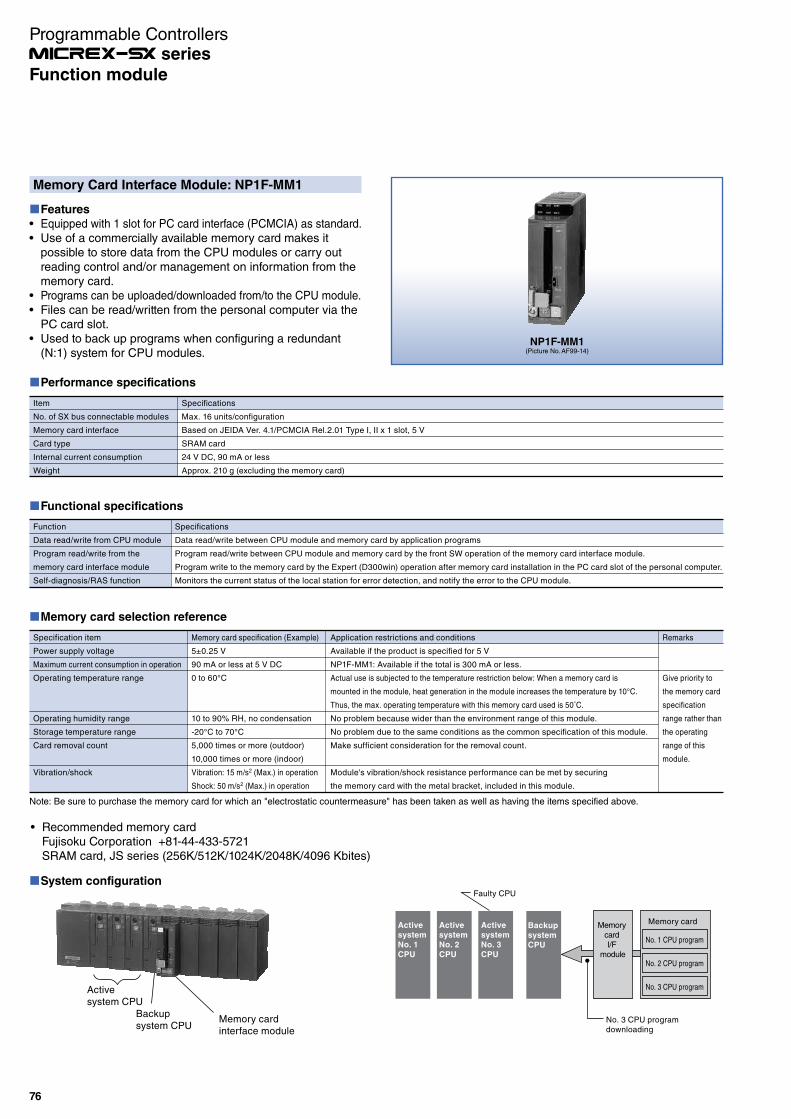
Memory Card Interface Module: NP1F-MM1
Features
Equipped with 1 slot for PC card interface (PCMCIA) as standard.Use of a commercially available memory card makes it possible to store data from the CPU modules or carry out reading control and/or management on information from the memory card.Programs can be uploaded/downloaded from/to the CPU module.Files can be read/written from the personal computer via the PC card slot.Used to back up programs when configuring a redundant (N:1) system for CPU modules.
Performance specifications
Item
No. of SX bus connectable modules
Memory card interface
Card type
Internal current consumption
Weight
Specifications
Max. 16 units/configuration
Based on JEIDA Ver. 4.1/PCMCIA Rel.2.01 Type I, II x 1 slot, 5 V
SRAM card
24 V DC, 90 mA or less
Approx. 210 g (excluding the memory card)
Functional specifications
Function
Data read/write from CPU module
Program read/write from the
memory card interface module
Self-diagnosis/RAS function
Specifications
Data read/write between CPU module and memory card by application programs
Program read/write between CPU module and memory card by the front SW operation of the memory card interface module.
Program write to the memory card by the Expert (D300win) operation after memory card installation in the PC card slot of the personal computer.
Monitors the current status of the local station for error detection, and notify the error to the CPU module.
Memory card selection reference
Specification item
Power supply voltage
Maximum current consumption in operation
Operating temperature range
Operating humidity range
Storage temperature range
Card removal count
Vibration/shock
Memory card specification (Example)
5±0.25 V
90 mA or less at 5 V DC
0 to 60°C
10 to 90% RH, no condensation
-20°C to 70°C
5,000 times or more (outdoor)
10,000 times or more (indoor)
Vibration: 15 m/s2 (Max.) in operation
Shock: 50 m/s2 (Max.) in operation
Application restrictions and conditions
Available if the product is specified for 5 V
NP1F-MM1: Available if the total is 300 mA or less.
Actual use is subjected to the temperature restriction below: When a memory card is
mounted in the module, heat generation in the module increases the temperature by 10°C.
Thus, the max. operating temperature with this memory card used is 50˚C.
No problem because wider than the environment range of this module.
No problem due to the same conditions as the common specification of this module.
Make sufficient consideration for the removal count.
Module's vibration/shock resistance performance can be met by securing
the memory card with the metal bracket, included in this module.
Remarks
Give priority to
the memory card
specification
range rather than
the operating
range of this
module.
Note: Be sure to purchase the memory card for which an "electrostatic countermeasure" has been taken as well as having the items specified above.
NP1F-MM1(Picture No. AF99-14)
System configuration
Memory card I/F
module
Memory card
No. 1 CPU program
No. 2 CPU program
No. 3 CPU program
No. 3 CPU program downloading
Faulty CPU
Active
system
No. 1
CPU
Active
system
No. 2
CPU
Active
system
No. 3
CPU
Backup
system
CPU
Memory card interface module
Backup system CPU
Active system CPU
Recommended memory cardFujisoku Corporation +81-44-433-5721SRAM card, JS series (256K/512K/1024K/2048K/4096 Kbites)
76
Function module
Programmable Controllers series

Dummy Module: NP1F-DMY
Features
When your system will be expanded in the future, the dummy module can be used as a substitute for the extension module.If an active module has failed during operation of the system, the system can be restarted when you replace the failed module with the dummy module (which, however, cannot perform the functions of the failed module).
Specifications
Item
Model
Position on which a substitutable
module can be mounted.
No. of occupied words
Internal current consumption
Weight
Specifications
NP1F-DMY
All modules except power supply module and CPU module
On a base board directly connected to SX bus
Cannot be mounted on a T-link base board or other remote I/O module.
0 words
24 V DC, 26 mA or less
Approx. 120 g
NP1F-DMY(Picture No. AF00-44)
77
Function Module
Programmable Controllers series
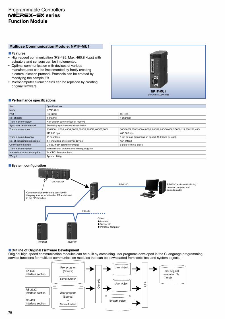
Multiuse Communication Module: NP1F-MU1
Features
High-speed communication (RS-485: Max. 460.8 kbps) with actuators and sensors can be implemented.Optimal communication with devices of various manufacturers can be implemented by freely creating a communication protocol. Protocols can be created by modifying the sample FB.Microcomputer circuit boards can be replaced by creating original firmware.
Performance specifications
Item
Model
Port
No. of ports
Transmission system
Synchronization method
Transmission speed
Transmission distance
No. of connectable modules
Connection method
Transmission system
Internal current consumption
Weight
Specifications
NP1F-MU1
RS-232C
1 channel
Half-duplex communication method
Start-stop synchronous transmission
300/600/1,200/2,400/4,800/9,600/19,200/38,400/57,600/
115,200 bps
15 m or less
1:1 (including one external device)
D-sub, 9-pin connector (male)
Transmission protocol by creating program
24 V DC, 80 mA or less
Approx. 140 g
RS-485
1 channel
300/600/1,200/2,400/4,800/9,600/19,200/38,400/57,600/115,200/230,400/
460,800 bps
1 km or less (transmission speed: 19.2 kbps or less)
1:31 (Max.)
6-pole terminal block
System configuration
Outline of Original Firmware DevelopmentOriginal high-speed communication modules can be built by combining user programs developed in the C language programming, service functions for multiuse communication modules that can be downloaded from websites, and system objects.
User program
(Source)
+
Service function
User object
User object
User program
(Source)
+
Service function
User original execution file(*.mot)
System object
Com
pile
Lin
k
RS-232CInterface section
SX busInterface section
RS-485Interface section
NP1F-MU1(Picture No. KDD05-018)
RS-232C equipment including personal computer and barcode reader
Communication software is described in the programs as an extended FB and stored in the CPU module.
MICREX-SX
RS-232C
RS-485
InverterInverter
Others
ActuatorSensor etc.,Personal computer
78
Programmable Controllers series
Function Module

Flow Meter F/AD Conversion Module: NP1F-PI4
Features
Instantaneous and cumulative flows can be displayed at the same time.Various flow meters can be connected.· No-voltage semiconductor input (two-wire/three-wire)· Voltage input (two-wire/three-wire)· Two-wire current input· Two-wire contact inputA transducer is unnecessary as the module is insulated with high pressure-resistance (1000 V AC) between channels.A displacement type flow meter (oval type flow meter) can be connected.
External wiring
1
2
4
6
8
10
12
14
16
18
20
3
5
7
9
11
13
15
17
19
CH1
Receiver
CH2
CH3
CH4
SLD terminals are internally connected.
SUP1+SIG1
NC
SIG2
NC
SIG3
SIG4
NC
NC
COM1
SUP2+
COM2
SUP3+
COM3
SUP4+
COM4
Filter setting switching exampleTransmitter
13.5V/24V
SW1 SW2
RL FIL
13.5V/24V
SW1 SW2
RL FIL
3-line open collector pulse
SW1:off SW2: ON as needed Transmitter power supply: 13.5 V/ 24 V selection
Non-voltage contact pulse
SW1:off SW2: ON as needed
Transmitter 13.5V/24V
SW1 SW2
RL FIL
Transmitter 13.5V/24V
SW1 SW2
RL FIL
2-line /3-line voltage pulse
SW1:off SW2: ON as needed Transmitter power supply: 13.5 V/ 24 V
SW1: 200 Ω or 500 Ω ON SW2: ON as needed Transmitter power supply: 13.5 V/ 24 V
Current pulse
13.5V
SW1 SW2
RL FIL
Non-voltage contact pulse
SW1:1 kΩ SW2: ON as needed Transmitter power supply: 13.5 V
COM1
SIG1
V1
COM1
SIG1
V1
COM1
SIG1
V1
COM1
SIG1
V1
COM1
SIG1
V1
SpecificationsItem Specifications
Model NP1F-PI4
No. of input points 4 points
Connected sensor inputs
No-voltage contact pulse, 2-wired open-collector pulse, 3-wired open-collector pulse, 2-wired voltage pulse, 3-wired voltage pulse, 2-wired current pulse
Input frequency 0 to 10 kHz
Input wave form Nearly square wave
Pull-up resistor 22 kΩ
Max. allowed input -1 to 30 V, 0 to 30 mA
Min. pulse width 50 µs or more (50 ms or more when filter is set)
Inputsignallevel
Contact input(Relay/ transistor)
Detection level: ON: 200 Ω or less, OFF: 100 kΩ or moreContact capacity: When the sensor power supply is 13.5 V:
15 V DC, 15 mA or moreWhen the sensor power supply is 24 V: 30 V DC, 30 mA or more
Voltage/current pulse
Detection level: 3 Vp-p (Current input: Voltage-converted value indicated to the left)
Input impedance Disabled (10 kΩ or more), 200 Ω, 500 Ω or 1 kΩ can be selected.
Input pulse detection AC coupling or rising-edge detection
Integrated value update cycle 5 ms/4 points (1 ms, when for only integrated value mode)
Response time Integrated value update cycle + tact cycleInstant value update cycle + tact cycle
Sensor power supply(Where Ta = 25°C)
*1
1) Output voltage: 13.5 V DC ±15%/24 V DC ±15% (Selection of either one)2) Permissible current; when 13.5 V DC: 35 mA or less, when 24 V DC: 24 mA or less3) Short-circuit limitation current; when 13.5 V DC: approx. 40 mA,
when 24 V DC: approx. 28 mA4) Ripple noise: Approx. 250 mV (p-p) or less5) Sudden change of the load: 3 V (0-P) or less (condition of
sudden change of the load: 0 to 40 mA)
Filter function The filter for the chattering removal can be selected. (time constant: approx. 4 ms)
No. of occupied words Input: 8 words + output 4 words
Insulation method Photo-coupler insulation and transformer insulation (Between pulse input terminals and FG)Transformer insulation (Between pulse input terminals and channels)
Dielectric strength 1000 V AC, 1 minutebetween pulse input terminals and FG (short circuit current: 10 mA)
1000 V AC, 1 minutebetween pulse input terminals and channels (short circuit current: 10 mA)
Insulation resistance 10 MΩ or more with 500 V DC meggerbetween pulse input terminals and FG
10 MΩ or more with 500 V DC meggerbetween pulse input terminals and channels
Internal current consumption *2
390 mA or less (When the sensor power supply is used.)200 mA or less (When the sensor power supply is not used.)
Non use output treatment Basically, open
Applicable cable Use the twisted pair wire with the shield. (Wiring length: 500 m or less)
Weight Approx. 330 g
External connections Detachable screw terminal block (M3 x 20 poles)
*1 An ambient temperature during short circuit should be 40°C or less. *2 This can be reduced depending on the used number of channels and the
used number of sensor power supplies.
Characteristic diagram
In the case of the input frequency range: 0 to 200 Hz and the instant value unit (INT type): 0 to 23000.
Instantaneous value (INT type)
Input frequency (Hz)
0 to 200 Hz200
20000
79
Programmable Controllers series
Function Module
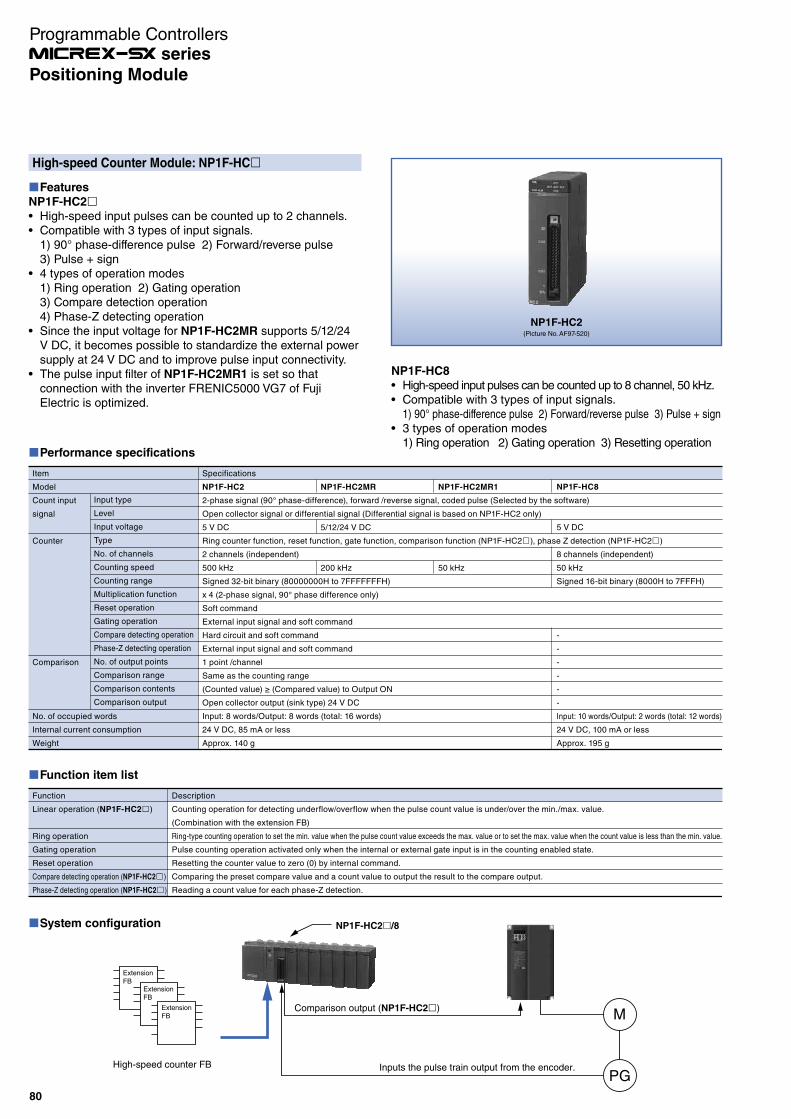
High-speed Counter Module: NP1F-HC
Features
NP1F-HC2
High-speed input pulses can be counted up to 2 channels.Compatible with 3 types of input signals.1) 90° phase-difference pulse 2) Forward/reverse pulse3) Pulse + sign 4 types of operation modes1) Ring operation 2) Gating operation3) Compare detection operation4) Phase-Z detecting operationSince the input voltage for NP1F-HC2MR supports 5/12/24 V DC, it becomes possible to standardize the external power supply at 24 V DC and to improve pulse input connectivity.The pulse input filter of NP1F-HC2MR1 is set so that connection with the inverter FRENIC5000 VG7 of Fuji Electric is optimized.
NP1F-HC2(Picture No. AF97-520)
Performance specifications
Item
Model
Count input
signal
Counter
Comparison
No. of occupied words
Internal current consumption
Weight
Input type
Level
Input voltage
Type
No. of channels
Counting speed
Counting range
Multiplication function
Reset operation
Gating operation
Compare detecting operation
Phase-Z detecting operation
No. of output points
Comparison range
Comparison contents
Comparison output
Specifications
NP1F-HC2
2-phase signal (90° phase-difference), forward /reverse signal, coded pulse (Selected by the software)
Open collector signal or differential signal (Differential signal is based on NP1F-HC2 only)
5 V DC
Ring counter function, reset function, gate function, comparison function (NP1F-HC2 ), phase Z detection (NP1F-HC2 )
2 channels (independent)
500 kHz
Signed 32-bit binary (80000000H to 7FFFFFFFH)
x 4 (2-phase signal, 90° phase difference only)
Soft command
External input signal and soft command
Hard circuit and soft command
External input signal and soft command
1 point /channel
Same as the counting range
(Counted value) ≥ (Compared value) to Output ON
Open collector output (sink type) 24 V DC
Input: 8 words/Output: 8 words (total: 16 words)
24 V DC, 85 mA or less
Approx. 140 g
NP1F-HC8
5 V DC
8 channels (independent)
50 kHz
Signed 16-bit binary (8000H to 7FFFH)
-
-
-
-
-
-
Input: 10 words/Output: 2 words (total: 12 words)
24 V DC, 100 mA or less
Approx. 195 g
NP1F-HC2MR1
50 kHz
NP1F-HC2MR
5/12/24 V DC
200 kHz
Function item list
Function
Linear operation (NP1F-HC2 )
Ring operation
Gating operation
Reset operation
Compare detecting operation (NP1F-HC2 )
Phase-Z detecting operation (NP1F-HC2 )
Description
Counting operation for detecting underflow/overflow when the pulse count value is under/over the min./max. value.
(Combination with the extension FB)
Ring-type counting operation to set the min. value when the pulse count value exceeds the max. value or to set the max. value when the count value is less than the min. value.
Pulse counting operation activated only when the internal or external gate input is in the counting enabled state.
Resetting the counter value to zero (0) by internal command.
Comparing the preset compare value and a count value to output the result to the compare output.
Reading a count value for each phase-Z detection.
NP1F-HC8
High-speed input pulses can be counted up to 8 channel, 50 kHz.Compatible with 3 types of input signals.1) 90° phase-difference pulse 2) Forward/reverse pulse 3) Pulse + sign3 types of operation modes1) Ring operation 2) Gating operation 3) Resetting operation
System configuration
Inputs the pulse train output from the encoder.
Comparison output (NP1F-HC2 )
ExtensionFB
ExtensionFB
ExtensionFB M
PG
NP1F-HC2 /8
High-speed counter FB
80
Positioning Module
Programmable Controllers series

Two-axis Pulse Train Output Positioning Control Module: NP1F-HP2
NP1F-HP2(Picture No. AF97-517)
Extension FB
ExtensionFB
ExtensionFB
ExtensionFB
Command pulse
NP1F-HP2
Servo amplifier
Servo amplifier
P
G
P
G
-OT Origin +OT
System configuration
Performance specifications
Item
No. of control axes
Positioning control
Acceleration/deceleration characteristics
Max. position data
Pulse train command
Control functions
Combination actuator
No. of occupied words
Internal current consumption
Externally supplied power
Weight
Specifications
2 axes
Open loop
Trapezoidal acceleration/deceleration (at pulse generation mode)
Max. 232-1 pulse /command
250 kHz
16 bits/20 bits
Open collector output (forward pulse + reverse pulse)
1 type (Pulse generation mode)
Servo system prepared pulse train command input or stepping motor
Input: 8 words/Output: 8 words (total: 16 words)
24 V DC, 95 mA or less
24 V DC, 35mA or less
Approx. 180 g
Command frequency
Frequency resolution
Output type
Features
Combined with the servo amplifier motor of the pulse train command input type or the stepping motor driver allows high-precision positioning.Use of an extension FB facilitates embedding of the necessary functions including axis-independent single-function positioning to multi-axis simultaneous start positioning (pseudo linear interpolation).
81
Positioning Module
Programmable Controllers series

Two-axis Pulse Train Multiple Positioning Control Module: NP1F-MP2
Features
Combined with the servo amplifier motor of the pulse train command input type or the stepping motor driver allows high-precision positioning.Use of an extension FB facilitates embedding of the necessary functions including axis-independent single-function positioning to multi-axis simultaneous start positioning (pseudo linear interpolation), interpolation, and cam/running cut.Current position (current feedback value) can be detected with the feedback pulse. Two types of operation modes are available (pulse generation mode and position command mode)
Performance specifications
Item
No. of control axes
Positioning control
Acceleration/deceleration characteristics
Max. position data
Pulse train command
Feedback pulse
Manual pulse unit
Control functions
Combination actuator
No. of occupied words
Internal current consumption
Externally supplied power
Weight
Specifications
2 axes
Open loop
Trapezoidal acceleration/deceleration (at pulse generation mode)
Max. 232-1 pulse/command
250 kHz
16 bits/20 bits
Open collector output (forward pulse + reverse pulse)
500 kHz
Open collector input or differential signal (90˚ phase difference, phase A, B and phase Z)
500 kHz
Open collector input or differential signal (90˚ phase difference, phase A, B or forward pulse + reverse pulse)
2 types (Pulse generation mode, positioning command mode)
Servo system prepared pulse train command input or stepping motor
Input: 14 words/Output: 8 words (total: 22 words)
24 V DC, 95 mA or less
24 V DC, 35mA or less
Approx. 200 g
Command frequency
Frequency resolution
Output type
Input frequency
Input type
Input frequency
Input type
NP1F-MP2(Picture No. AF97-518)
ExtensionFB
ExtensionFB
ExtensionFB
Extension FB
Command pulse
NP1F-MP2
Feedback pulse
Servo amplifier
Servo amplifier
PG
PG
-OT Origin +OT
PG
82
Positioning Module
Programmable Controllers series
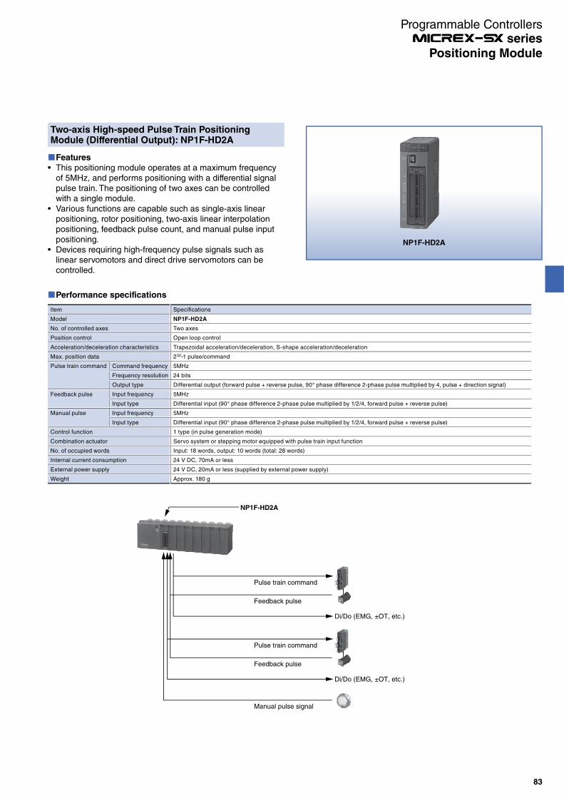
Two-axis High-speed Pulse Train Positioning Module (Differential Output): NP1F-HD2A
Features
This positioning module operates at a maximum frequency of 5MHz, and performs positioning with a differential signal pulse train. The positioning of two axes can be controlled with a single module.Various functions are capable such as single-axis linear positioning, rotor positioning, two-axis linear interpolation positioning, feedback pulse count, and manual pulse input positioning.Devices requiring high-frequency pulse signals such as linear servomotors and direct drive servomotors can be controlled.
Performance specifications
Item
Model
No. of controlled axes
Position control
Acceleration/deceleration characteristics
Max. position data
Pulse train command
Feedback pulse
Manual pulse
Control function
Combination actuator
No. of occupied words
Internal current consumption
External power supply
Weight
Specifications
NP1F-HD2A
Two axes
Open loop control
Trapezoidal acceleration/deceleration, S‐shape acceleration/deceleration
232-1 pulse/command
5MHz
24 bits
Differential output (forward pulse + reverse pulse, 90° phase difference 2-phase pulse multiplied by 4, pulse + direction signal)
5MHz
Differential input (90° phase difference 2-phase pulse multiplied by 1/2/4, forward pulse + reverse pulse)
5MHz
Differential input (90° phase difference 2-phase pulse multiplied by 1/2/4, forward pulse + reverse pulse)
1 type (in pulse generation mode)
Servo system or stepping motor equipped with pulse train input function
Input: 18 words, output: 10 words (total: 28 words)
24 V DC, 70mA or less
24 V DC, 20mA or less (supplied by external power supply)
Approx. 180 g
Command frequency
Frequency resolution
Output type
Input frequency
Input type
Input frequency
Input type
NP1F-HD2A
Pulse train command
Di/Do (EMG, ±OT, etc.)
NP1F-HD2A
Feedback pulse
Pulse train command
Di/Do (EMG, ±OT, etc.)
Feedback pulse
Manual pulse signal
83
Positioning Module
Programmable Controllers series
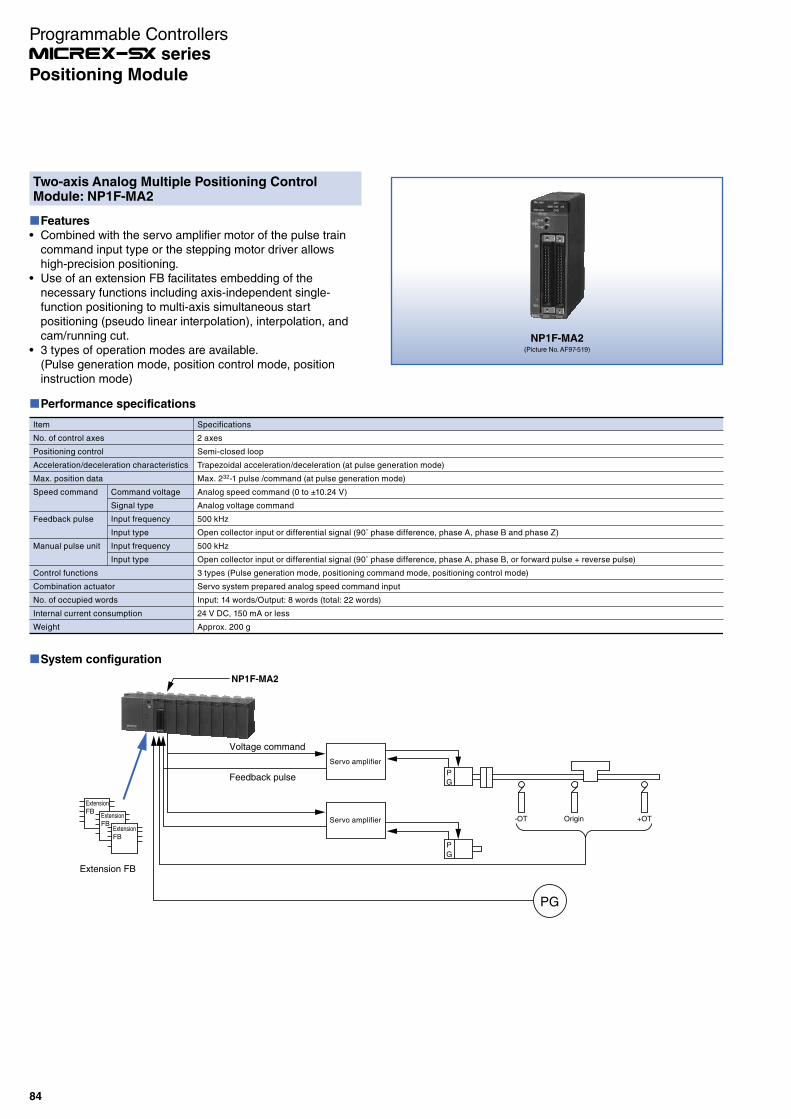
Two-axis Analog Multiple Positioning Control Module: NP1F-MA2
Features
Combined with the servo amplifier motor of the pulse train command input type or the stepping motor driver allows high-precision positioning.Use of an extension FB facilitates embedding of the necessary functions including axis-independent single-function positioning to multi-axis simultaneous start positioning (pseudo linear interpolation), interpolation, and cam/running cut.3 types of operation modes are available.(Pulse generation mode, position control mode, position instruction mode)
NP1F-MA2(Picture No. AF97-519)
Performance specifications
Item
No. of control axes
Positioning control
Acceleration/deceleration characteristics
Max. position data
Speed command
Feedback pulse
Manual pulse unit
Control functions
Combination actuator
No. of occupied words
Internal current consumption
Weight
Specifications
2 axes
Semi-closed loop
Trapezoidal acceleration/deceleration (at pulse generation mode)
Max. 232-1 pulse /command (at pulse generation mode)
Analog speed command (0 to ±10.24 V)
Analog voltage command
500 kHz
Open collector input or differential signal (90˚ phase difference, phase A, phase B and phase Z)
500 kHz
Open collector input or differential signal (90˚ phase difference, phase A, phase B, or forward pulse + reverse pulse)
3 types (Pulse generation mode, positioning command mode, positioning control mode)
Servo system prepared analog speed command input
Input: 14 words/Output: 8 words (total: 22 words)
24 V DC, 150 mA or less
Approx. 200 g
Command voltage
Signal type
Input frequency
Input type
Input frequency
Input type
System configuration
ExtensionFB
ExtensionFB
ExtensionFB
Extension FB
Voltage command
NP1F-MA2
Feedback pulse
Servo amplifier
P
G
Servo amplifier
P
G
-OT Origin +OT
PG
84
Programmable Controllers series
Positioning Module

4-axis Pulse Train Output Positioning Control Unit:NR1SF-HP4DT
Features
Combined with the servo amplifier motor of the pulse train command input type or the stepping motor driver allows high-precision positioning.Minimum program for data setting and command operation that does not need an extension FB allows you to control the positioning.
NR1SF-HP4DT
Performance specifications
Item
Model
No. of control axes
Speed command
Feedback pulse input
External pulse input
DI signal
No. of occupied words
Internal current consumption
Externally supplied power
Weight
Command signal
Max. command frequency
Output format
Max. load current
Insulation method
Signal type
No. of points
Input format
Input model
Rated current
Input impedance
Insulation method
No. of points for common
Specifications
NR1SF-HP4DT
4 axes
Pulse train command
250 kHz (conditions: shielded twist pair cable: 2 m or less)
Open collector, sink output
50 mA (24 V DC)
Photocoupler insulation
Forward pulse (CW) + reverse pulse (CCW)
None
None
8 points (2 points / axis)
Origin LS (x 4 CH)
Timing signal / Phase Z (x 4 CH)
Source input (non-voltage contact input)
DC (IEC 61131-2 type 2)
Approx. 4 mA (24 V DC)
Approx. 5.6 kΩ
Photocoupler insulation
2 points (It allows with the common extension bar.)
Total: 40 words (input: 16 words / output: 24 words)
24 V DC, 20 mA or less
24 V DC, 150 mA or less
Approx. 230 g
System configuration
Command pulse
SX bus
Max. 4 axes
NR1SF-HP4DT
Servo amplifier
Servo amplifier
P
G
P
G
Origin
85
Programmable Controllers series
Positioning Module
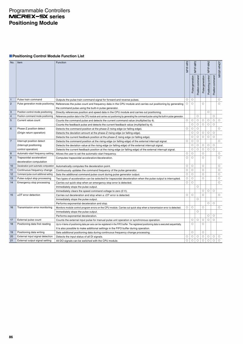
Positioning Control Module Function List
No. Item Function
1
2
3
4
5
6
7
8
9
10
11
12
13
14
15
16
17
18
19
20
21
Pulse train command
Pulse generation mode positioning
Position control mode positioning
Position command mode positioning
Current value count
Phase-Z position detect
(Origin return operation)
Interrupt position detect
(Interrupt positioning
control operation)
Automatic-start frequency setting
Trapezoidal acceleration/
deceleration computation
Deceleration point automatic computation
Continuous frequency change
Command pulse count additional setting
Pulse output stop processing
Emergency stop processing
±OT error detection
Transmission error monitoring
External pulse count
Positioning data first reading
Positioning data writing
External input signal detection
External output signal setting
NP
1F-H
P2
NR
1SF
-HP
4D
T
Puls
e g
enera
tion
Posi
tion c
om
mand
Puls
e g
enera
tion
Posi
tionin
g c
ontrol
Posi
tion c
om
mand
NP
1F-M
P2
NP
1F-M
A2
Outputs the pulse train command signal for forward and reverse pulses.
References the pulse count and frequency data in the CPU module and carries out positioning by generating
the command pulse using the built-in pulse generator.
Directly references position and speed data in the CPU module and carries out positioning.
References position data in the CPU module and carries out positioning by generating the command pulse using the built-in pulse generator.
Counts the command pulse and detects the current command value (multiplied by 4).
Counts the feedback pulse and detects the current feedback value (multiplied by 4).
Detects the command position at the phase-Z rising edge (or falling edge).
Detects the deviation amount at the phase-Z rising edge (or falling edge).
Detects the current feedback position at the phase-Z rising edge (or falling edge).
Detects the command position at the rising edge (or falling edge) of the external interrupt signal.
Detects the deviation value at the rising edge (or falling edge) of the external interrupt signal.
Detects the current feedback position at the rising edge (or falling edge) of the external interrupt signal.
Allows the user to set the automatic-start frequency.
Computes trapezoidal acceleration/deceleration.
Automatically computes the deceleration point.
Continuously updates the command frequency of the pulse generator.
Sets the additional command pulse count during pulse generator output.
Two types of acceleration can be selected for trapezoidal deceleration when the pulse output is interrupted.
Carries out quick stop when an emergency stop error is detected.
Immediately stops the pulse output.
Immediately clears the speed command voltage to zero (0 V).
Carries out deceleration and stop when a OT error is detected.
Immediately stops the pulse output.
Performs exponential deceleration and stop.
Monitors module control program errors on the CPU module. Carries out quick stop when a transmission error is detected.
Immediately stops the pulse output.
Performs exponential deceleration.
Counts the external input pulse for manual pulse unit operation or synchronous operation.
Up to 4 items of positioning data per axis can be registered in the FIFO buffer. The registered positioning data is executed sequentially.
It is also possible to make additional settings in the FIFO buffer during operation.
Sets additional positioning data during continuous frequency change processing.
Detects the input status of all DI signals.
All DO signals can be switched with the CPU module.
Programmable Controllers series
86
Positioning Module
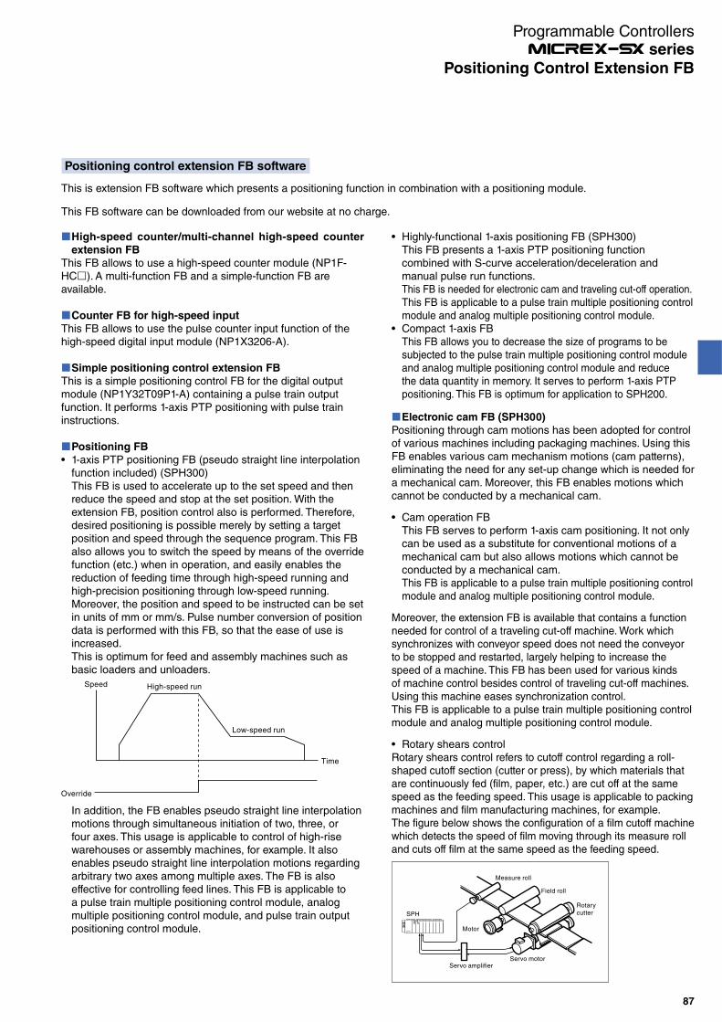
Positioning control extension FB software
This is extension FB software which presents a positioning function in combination with a positioning module.
This FB software can be downloaded from our website at no charge.
High-speed counter/multi-channel high-speed counter
extension FB
This FB allows to use a high-speed counter module (NP1F-HC ). A multi-function FB and a simple-function FB are available.
Counter FB for high-speed input
This FB allows to use the pulse counter input function of the high-speed digital input module (NP1X3206-A).
Simple positioning control extension FB
This is a simple positioning control FB for the digital output module (NP1Y32T09P1-A) containing a pulse train output function. It performs 1-axis PTP positioning with pulse train instructions.
Positioning FB
1-axis PTP positioning FB (pseudo straight line interpolation function included) (SPH300)This FB is used to accelerate up to the set speed and then reduce the speed and stop at the set position. With the extension FB, position control also is performed. Therefore, desired positioning is possible merely by setting a target position and speed through the sequence program. This FB also allows you to switch the speed by means of the override function (etc.) when in operation, and easily enables the reduction of feeding time through high-speed running and high-precision positioning through low-speed running. Moreover, the position and speed to be instructed can be set in units of mm or mm/s. Pulse number conversion of position data is performed with this FB, so that the ease of use is increased.This is optimum for feed and assembly machines such as basic loaders and unloaders.
Speed High-speed run
Low-speed run
Time
Override
In addition, the FB enables pseudo straight line interpolation motions through simultaneous initiation of two, three, or four axes. This usage is applicable to control of high-rise warehouses or assembly machines, for example. It also enables pseudo straight line interpolation motions regarding arbitrary two axes among multiple axes. The FB is also effective for controlling feed lines. This FB is applicable to a pulse train multiple positioning control module, analog multiple positioning control module, and pulse train output positioning control module.
Electronic cam FB (SPH300)
Positioning through cam motions has been adopted for control of various machines including packaging machines. Using this FB enables various cam mechanism motions (cam patterns), eliminating the need for any set-up change which is needed for a mechanical cam. Moreover, this FB enables motions which cannot be conducted by a mechanical cam.
Cam operation FBThis FB serves to perform 1-axis cam positioning. It not only can be used as a substitute for conventional motions of a mechanical cam but also allows motions which cannot be conducted by a mechanical cam.This FB is applicable to a pulse train multiple positioning control module and analog multiple positioning control module.
Moreover, the extension FB is available that contains a function needed for control of a traveling cut-off machine. Work which synchronizes with conveyor speed does not need the conveyor to be stopped and restarted, largely helping to increase the speed of a machine. This FB has been used for various kinds of machine control besides control of traveling cut-off machines. Using this machine eases synchronization control.This FB is applicable to a pulse train multiple positioning control module and analog multiple positioning control module.
Rotary shears controlRotary shears control refers to cutoff control regarding a roll-shaped cutoff section (cutter or press), by which materials that are continuously fed (film, paper, etc.) are cut off at the same speed as the feeding speed. This usage is applicable to packing machines and film manufacturing machines, for example.The figure below shows the configuration of a film cutoff machine which detects the speed of film moving through its measure roll and cuts off film at the same speed as the feeding speed.
Servo motor
Motor
SPH
Servo amplifier
Measure roll
Field roll
Rotary cutter
Highly-functional 1-axis positioning FB (SPH300)This FB presents a 1-axis PTP positioning function combined with S-curve acceleration/deceleration and manual pulse run functions. This FB is needed for electronic cam and traveling cut-off operation.This FB is applicable to a pulse train multiple positioning control module and analog multiple positioning control module.Compact 1-axis FBThis FB allows you to decrease the size of programs to be subjected to the pulse train multiple positioning control module and analog multiple positioning control module and reduce the data quantity in memory. It serves to perform 1-axis PTP positioning. This FB is optimum for application to SPH200.
Programmable Controllers series
87
Positioning Control Extension FB

Functional Extension FB Software
Easily realizes functional extension by software
External fault diagnostic and adjustment system functions can also be implemented with software (an expansion FB) by using the enhanced processing functions of the CPU module.The software processing section is placed in the CPU section as an expansion FB and only the external equipment interface processing is separately performed in the I/O section. Thus, an optimum system can be configured according to the function of performance requirements.
Diagnostic FB
Necessary diagnosis can be conducted only by selecting an extended FB for each diagnostic function. If this software is stored in the CPU module for control programs, it is unnecessary to add any other special function module. When it is used in the multi-CPU configuration, independence of the control CPU can also be preserved.For notification of the diagnostic results to the external equipment, Ethernet or a network of general-purpose communication modules or equivalent can also be used.
Extension FB which implement the malfunction diagnostic functionsThe following diagnostic and data sampling FBs are available:· Sequence/time diagnostic FB· Time diagnostic FB· Upper/lower limit diagnostic FB· Data sampling FB
PID FB
Instrumentation control and sequence control were conventionally separated with respect to both hardware and software. When packaged as an extended FB, this adjustment system computing function is a true linkage between instrumentation control and sequence control.In addition, the restriction on the control loop count has sufficient expandability in a multi-CPU configuration. The number of FBs that can be stored in a CPU module is limited by the number of program steps and the sampling rate.
Extension FB realizing the temperature regulation system· ON/OFF control FB· PID FB with auto-tuning
Flying shears controlFlying shears control refers to cutoff control regarding a cutoff section (cutter or press) containing ball screws or racks/pinions, by which materials that are continuously fed (iron plates, external wall materials, clay, etc.) are cut off at the same speed as the feeding speed. This usage is applicable to metalworking machines, tile manufacturing machines, and painting machines, for example. The figure below shows the configuration of a tile manufacturing machine which detects the speed of clay moving through its measure roll and cuts off clay while synchronizing its rotating knife blade with the clay's speed.
Servo motor
Motor
Encoder
Servo amplifier
SPH
Flying cutter controlFlying cutter control refers to cutoff control regarding a cutoff section (cutter or water jet) containing ball screws, racks/pinions, and chains by which materials that are continuously fed (film, paper, plastic, etc.) are cut off at a determined angle at the speed which is proportional to the feeding speed. This usage is applicable to board manufacturing machines, for example. The figure below shows the configuration of a machine which detects the speed of paper or plastic moving through its encoder and cuts off the material by water jet synchronizing with the feeding speed of paper or plastic.
Servo amplifier
Servo motor
25°
SPH
VARICAM FBThis FB enables VARICAM functions. It detects the angle (current value of works) of the main axis of a machine and switches On and Off output signals of the set angle (work position) of the main axis.This FB is applicable to a pulse train multiple positioning control module, analog multiple positioning control module, and pulse train output positioning control module.
Programmable Controllers series
88
Positioning Control Extension FB
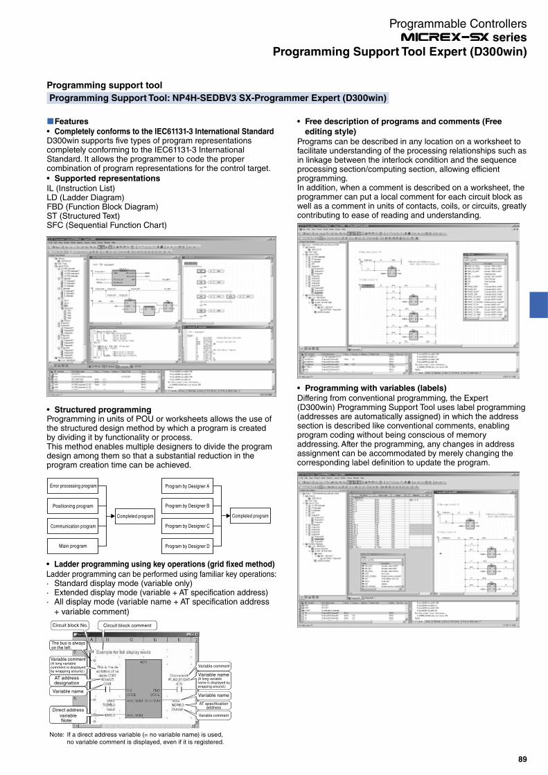
Programming support tool
Programming Support Tool: NP4H-SEDBV3 SX-Programmer Expert (D300win)
Features
Completely conforms to the IEC61131-3 International StandardD300win supports five types of program representations completely conforming to the IEC61131-3 International Standard. It allows the programmer to code the proper combination of program representations for the control target.
Supported representations
IL (Instruction List)LD (Ladder Diagram)FBD (Function Block Diagram)ST (Structured Text)SFC (Sequential Function Chart)
Structured programmingProgramming in units of POU or worksheets allows the use of the structured design method by which a program is created by dividing it by functionality or process.This method enables multiple designers to divide the program design among them so that a substantial reduction in the program creation time can be achieved.
Error processing program
Positioning program
Communication program
Main program
Completed program
Program by Designer A
Program by Designer B
Program by Designer C
Program by Designer D
Completed program
Free description of programs and comments (Free
editing style)
Programs can be described in any location on a worksheet to facilitate understanding of the processing relationships such as in linkage between the interlock condition and the sequence processing section/computing section, allowing efficient programming.In addition, when a comment is described on a worksheet, the programmer can put a local comment for each circuit block as well as a comment in units of contacts, coils, or circuits, greatly contributing to ease of reading and understanding.
Programming with variables (labels)
Differing from conventional programming, the Expert (D300win) Programming Support Tool uses label programming (addresses are automatically assigned) in which the address section is described like conventional comments, enabling program coding without being conscious of memory addressing. After the programming, any changes in address assignment can be accommodated by merely changing the corresponding label definition to update the program.
Ladder programming using key operations (grid fixed method)
Ladder programming can be performed using familiar key operations:· Standard display mode (variable only)· Extended display mode (variable + AT specification address)· All display mode (variable name + AT specification address
+ variable comment)
Variable comment(A long variablecomment is displayedby wrapping around.)
AT addressdesignation
Variable name
Direct addressvariableNote:
Circuit block No.
The bus is alwayson the left.
Circuit block comment
Note: If a direct address variable (= no variable name) is used,no variable comment is displayed, even if it is registered.
AT specificationaddress
Variable comment
Variable comment
Variable name
Variable name(A long variablename is displayed bywrapping around.)
Programmable Controllers series
89
Programming Support Tool Expert (D300win)
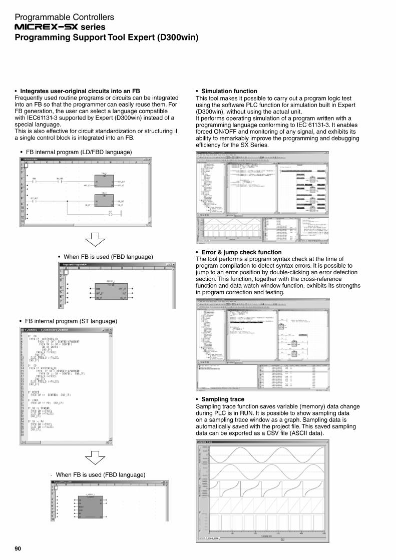
Integrates user-original circuits into an FBFrequently used routine programs or circuits can be integrated into an FB so that the programmer can easily reuse them. For FB generation, the user can select a language compatible with IEC61131-3 supported by Expert (D300win) instead of a special language.This is also effective for circuit standardization or structuring if a single control block is integrated into an FB.
FB internal program (LD/FBD language)
When FB is used (FBD language)
FB internal program (ST language)
· When FB is used (FBD language)
Simulation function
This tool makes it possible to carry out a program logic test using the software PLC function for simulation built in Expert (D300win), without using the actual unit.It performs operating simulation of a program written with a programming language conforming to IEC 61131-3. It enables forced ON/OFF and monitoring of any signal, and exhibits its ability to remarkably improve the programming and debugging efficiency for the SX Series.
Error & jump check functionThe tool performs a program syntax check at the time of program compilation to detect syntax errors. It is possible to jump to an error position by double-clicking an error detection section. This function, together with the cross-reference function and data watch window function, exhibits its strengths in program correction and testing.
Sampling trace
Sampling trace function saves variable (memory) data change during PLC is in RUN. It is possible to show sampling data on a sampling trace window as a graph. Sampling data is automatically saved with the project file. This saved sampling data can be exported as a CSV file (ASCII data).
Programmable Controllers series
90
Programming Support Tool Expert (D300win)
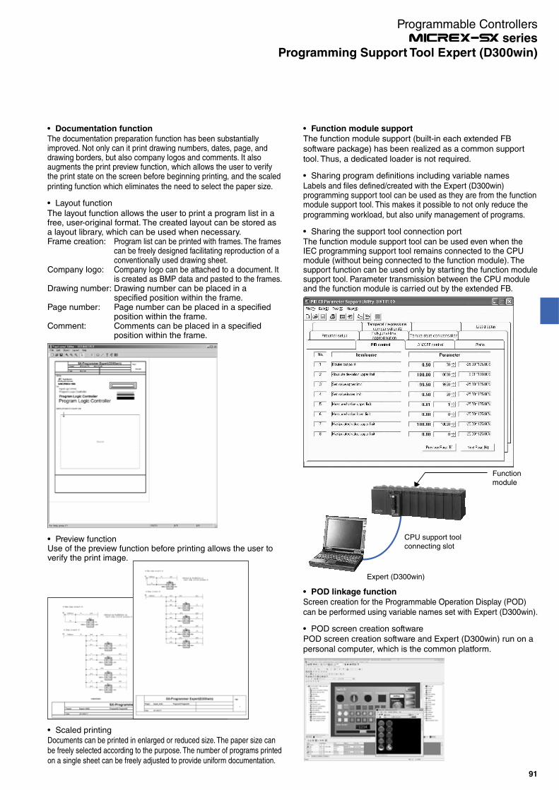
POD linkage function
Screen creation for the Programmable Operation Display (POD) can be performed using variable names set with Expert (D300win).
POD screen creation softwarePOD screen creation software and Expert (D300win) run on a personal computer, which is the common platform.
Documentation function
The documentation preparation function has been substantially improved. Not only can it print drawing numbers, dates, page, and drawing borders, but also company logos and comments. It also augments the print preview function, which allows the user to verify the print state on the screen before beginning printing, and the scaled printing function which eliminates the need to select the paper size.
Layout functionThe layout function allows the user to print a program list in a free, user-original format. The created layout can be stored as a layout library, which can be used when necessary.Frame creation: Program list can be printed with frames. The frames
can be freely designed facilitating reproduction of a conventionally used drawing sheet.
Company logo: Company logo can be attached to a document. It is created as BMP data and pasted to the frames.
Drawing number: Drawing number can be placed in a specified position within the frame.
Page number: Page number can be placed in a specified position within the frame.
Comment: Comments can be placed in a specified position within the frame.
Function module support
The function module support (built-in each extended FB software package) has been realized as a common support tool. Thus, a dedicated loader is not required.
Sharing program definitions including variable namesLabels and files defined/created with the Expert (D300win) programming support tool can be used as they are from the function module support tool. This makes it possible to not only reduce the programming workload, but also unify management of programs.
Sharing the support tool connection portThe function module support tool can be used even when the IEC programming support tool remains connected to the CPU module (without being connected to the function module). The support function can be used only by starting the function module support tool. Parameter transmission between the CPU module and the function module is carried out by the extended FB.
Functionmodule
CPU support tool connecting slot
Expert (D300win)
Preview functionUse of the preview function before printing allows the user to verify the print image.
Scaled printingDocuments can be printed in enlarged or reduced size. The paper size can be freely selected according to the purpose. The number of programs printed on a single sheet can be freely adjusted to provide uniform documentation.
Programmable Controllers series
91
Programming Support Tool Expert (D300win)

Multi-user support
A development environment that allows multiple users to simultaneously access a source project and has a mechanism for exclusive access control is offered.Exclusive control of projects is automatically performed by support tool operations.
Management, registration, and creation of client projects with respect to a server projectCheck-in/check-out in units of POU
USB interface
The connection method using the full-speed USB (Universal Serial Bus) 1.1 has been added as a loader connection method.
Operating environment
Item
Hardware
CPU
Hard disk
CD-ROM unit
Memory capacity
Keyboard
Mouse
Indicator
Communication
interface
OS
Portability
Environmental durability
Specifications
IBM-PC/AT compatible
Intel Pentium 400 MHz or higher (800 MHz or higher recommended)
Free space of 140 Mbytes or more Expert (D300win) system software: 100 MB or more
Standard extension FB software package: 40 MB or more
1 unit (x 4 speed or faster), media: ISO 9660 format
64 Mbytes or more (256 Mbytes or more recommended)
101 English keyboard
USB mouse, bus mouse, or PS2 mouse
800 x 600-dots resolution or higher (1024 x 768-dots resolution or higher recommended)
9600 to 57600 kbps (default setup according to resource model selection)
Possible
Possible (analog port is used)
Possible with V1.1 (Target CPU: SPH300 (NP1PS- R), SPH300EX, SPH2000 and SPH3000)
Possible
Possible
Possible
Windows XP/Vista/7
Depends on commercial mobile personal computer.
Depends on environmental conditions of commercial personal computer.
RS-232C
Ethernet
ISDN
USB
P/PE-link
SX bus
FL-net
Compatible with a Japanese and English OS
Compatible with a Japanese OS and English OS using the same format.
Password function
By setting an access authentication password for on-line functions, operation of the PLC can be limited to three levels, i.e., level 1, level 2, and level 3.
System configuration
Personal computer
SPH2000/SPH3000/SPH3000MM
SPH300 (R type)/SPH300EX/SPH3000/SPH3000MM
Ethernet crossover cable (commercial product)
USB/USB-miniB cable (commercial product)
USB/USB-B cable (commercial product)
SPH200/SPH300/SPH300EX/SPH2000/SPH3000/SPH3000MM
ExpertUSB/USB-mini B cable : 30cm (Supplied with NP4H-CVU)
Assist tool connection cable: NW0H-CA3+
USB/RS-422 signal converter: NP4H-CVU
Programmable Controllers series
92
Programming Support Tool Expert (D300win)

Features
Familiar user interface
The user interface and ladder programming support SPB programming equivalent to a FLEX-PC Windows-compatible PC loader.Support for full-keyboard operation is also handy for on-site debugging and maintenance.
Leverage your program assets
You can make good use of program assets for the MICREX-F and FLEX-PC series of our PLC. For circuits and commands not supported by Standard, alternative methods are described in the Help section.
Resume function
When the SPH starts to run, it automatically displays the position last edited or monitored.When you go on-line, monitoring starts at the position you were monitoring last time.When you are off-line, the system transitions to edit mode displaying the point you were editing last time.
Password function
By setting an access authentication password for on-line functions, operation of the PLC can be limited to three levels, i.e., level 1, level 2, and level 3.
SX-Programmer Standard MICREX-F loader
MICREX-SX
Conversion scope: F30 to F150S
(F200/F250 is possible by the range of the instruction of 150.)
Conversion (Copy & paste)
(Copy & paste)
(1) Instruction addressAddress allocation rules can be customized
(2) On-line help displays alternate methods for instructions that cannot be converted automatically.
FLEX-N loader
Conversion scope: All models (NB0 to NS)
Conversion (Copy & paste)
Supports a variety of input methodsStandard supports three input methods, and you can select the optimum input method for the situation.· Data can be input simply by operating the mouse wheel and
clicking the mouse button. You can register any command words you desire.
· Even if you do not know a command word, you can easily narrow down command words through a keyword search.
· Candidates can be automatically displayed by mnemonic input mainly using the keyboard and the Intellisense function.
Programming Support Tool: NP4H-SWN SX-Programmer Standard
Conforms to the IEC61131-3 International Standard
Program representations support the LD language, which is most standard.The ST and FBD programming languages are also supported.Programming in units of POU in which the structured design method is applicable can be performed.
Intuitive screen operation
The easy-to-see and understandable layout enables you to
intuitively operate the screen.
· Command word input is simplified by the command jog bar and the command word candidate narrow-down function based on a keyword search.
· Multiple sheet display and a flexible layout help improve operation efficiency.· Input can be completed on a single screen because
operands can be input in succession.· Operation help corresponding to the screen displayed
makes a manual no longer necessary.
Programmable Controllers series
93
Programming Support Tool Standard

Collation functionYou can display details of different points on programs and edit by referring to collation results.· You can quickly check different points with the aid of a filter
display of collation results.· You can edit a program while checking different points.· With the Update button, programs can be promptly updated
to the latest comparison results after editing.
Compatible with a Japanese and English OS
Compatible with a Japanese OS and English OS using the same format.
Operating environment
Item
Hardware
CPU
Hard disk
CD-ROM unit
Memory capacity
Keyboard
Mouse
Indicator
Communication
interface
OS
Portability
Environmental durability
Specifications
IBM-PC/AT compatible
Intel Pentium 233 MHz or higher (800 MHz or higher recommended)
Free space of 200 Mbytes or more
1 unit (x 4 speed or faster), media: ISO 9660 format
64 Mbytes or more (128 Mbytes or more recommended)
101 English keyboard
USB mouse, bus mouse, or PS2 mouse
800 x 600-dots resolution or higher (1024 x 768-dots resolution or higher recommended)
9600 to 57600 kbps (default setup according to resource model selection)
Possible (analog port is used)
Possible with V1.1 (Target CPU: SPH300 (NP1PS- R), SPH2000 and SHP3000)
Possible
Possible
Possible
Possible
Windows XP/Vista/7/8/8.1/10
Depends on commercial mobile personal computer.
Depends on environmental conditions of commercial personal computer.
RS-232C
Ethernet
ISDN
USB
P/PE-link
SX bus
FL-net
Personal computer
SPH
Standard
RS-232C
or
USB
System configuration
For information on how to connect Standard with PLC, refer to "System configuration" in Expert.
Device editor
Device information is displayed on a single screen, for example, in the form of a list of the operating states of devices, enabling you to save time in memory management.· Key operations are similar to those in Excel.· All addresses can be displayed.
· The device editor not only displays the operating state of
devices but also enables you to edit programs.
USB interface
The connection method using the full-speed USB (Universal Serial Bus) 1.1 has been added as a loader connection method.
Programmable Controllers series
94
Programming Support Tool Standard

Fuji Integrated Support Tool: NP4N-ITGR
Supported devices
Support Tool
Fuji Integrated Support Tool
@E.Integrator
PLC loader
SX-Programmer
POD editor
Inverter loader
PC Loader for FRENIC5000VG7
Servo loader
PC Loader for ALPHA5
Expert
Standard
Model
NP4N-ITGR
NP4H-SEDBV3
NP4H-SWN
V-SFT-5
WPS-VG7-PCL
-
Version (or Later)
V1.0.0.0
V3.4.4.0
V2.3.5.1
V5.2.0.0
V2.1.0.1
V1.8
Function and description
FA system integrated management tool that integratedly manages the
support tools for PLC, POD, INV, and SV.
Support tool for PLC. Edits the MICREX-SX program and monitors the
state.
Support tool for POD.
Edits and operates the POD screen.
Support tool for vector inverter VG7.
Adjusts parameters and monitors the state.
Support tool for ALPHA5.
Adjusts parameters and monitors the state.
Note: These support tools are not included in the Fuji integrated support tool.Purchase or download these support tools separately from our website.
Outline
Fuji Integrated Support Tool: @E.Integrator is a FA system integrated management tool that in an integrated way manages the support tools for PLC, POD, INV, and SV.
Features
Easy
· Relieved from cable switch work· Transparent connection with the
network· Relieved from tool select
operation
Economy
· Enhanced efficiency of content· Enhanced engineering efficiency
of all processesEvolution
· Pursuit of further convenience
Operating environment
Item
Operating system *1
Language
Processor
Hard disk
Memory
Display
Disk unit
Communication interface
Software *1
Description
Windows 2000 Professional, Windows XP, Windows 7
Japanese, English
Pentium 800 MHz or more
30 MB
256 MB
SVGA
CD-ROM drive unit (Used during installation)
RS-232C, USB, Ethernet
Microsoft Internet Explorer Version 5.01 or later
Microsoft .NET Framework 2.0
Microsoft .NET Framework 2.0 Japanese Language Pack *2
Item
Operating system
*1
Processor
Hard disk
Memory
Display
Description
Windows 2000 Professional
(Service Pack 4 or later)
Windows XP
(Service Pack 1 or later)
Pentium III 1 GHz or more
Free space of 1.5 GB or more
1GB
Recommended XGA or more
@E.Integrator operating environmentOperating environment combining @E.Integrator with each support tool
*1 Apply the latest service pack to your operating system.*2 If the Japanese Language Pack is not installed when using a Japanese OS, some messages will be displayed in English.
Servo loader
PLC loader
POD editor
Data flow
SX bus
Ethernet, FL-net, etc.
Engineering fromone location is possible and
switching of the loadercable is unnecessary
Inverter loader
Programmable Controllers series
95
Fuji Integrated Support Tool @E.Integrator
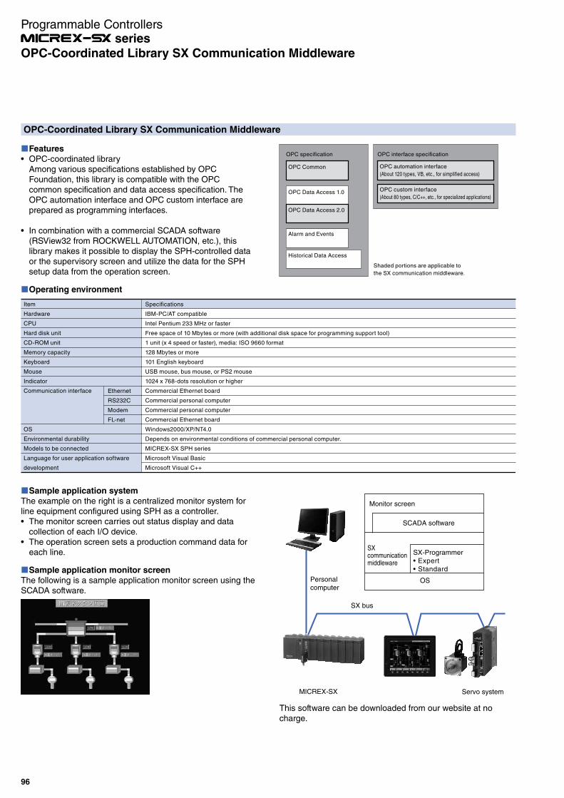
This software can be downloaded from our website at no charge.
Features
OPC-coordinated libraryAmong various specifications established by OPC Foundation, this library is compatible with the OPC common specification and data access specification. The OPC automation interface and OPC custom interface are prepared as programming interfaces.
In combination with a commercial SCADA software (RSView32 from ROCKWELL AUTOMATION, etc.), this library makes it possible to display the SPH-controlled data or the supervisory screen and utilize the data for the SPH setup data from the operation screen.
OPC-Coordinated Library SX Communication Middleware
OPC specification
OPC Common
OPC interface specification
OPC automation interface
(About 120 types, VB, etc., for simplified access)
OPC custom interface
(About 80 types, C/C++, etc., for specialized applications)OPC Data Access 1.0
OPC Data Access 2.0
Alarm and Events
Historical Data Access
Shaded portions are applicable to
the SX communication middleware.
Operating environment
Ethernet
RS232C
Modem
FL-net
Specifications
IBM-PC/AT compatible
Intel Pentium 233 MHz or faster
Free space of 10 Mbytes or more (with additional disk space for programming support tool)
1 unit (x 4 speed or faster), media: ISO 9660 format
128 Mbytes or more
101 English keyboard
USB mouse, bus mouse, or PS2 mouse
1024 x 768-dots resolution or higher
Commercial Ethernet board
Commercial personal computer
Commercial personal computer
Commercial Ethernet board
Windows2000/XP/NT4.0
Depends on environmental conditions of commercial personal computer.
MICREX-SX SPH series
Microsoft Visual Basic
Microsoft Visual C++
Item
Hardware
CPU
Hard disk unit
CD-ROM unit
Memory capacity
Keyboard
Mouse
Indicator
Communication interface
OS
Environmental durability
Models to be connected
Language for user application software
development
Sample application system
The example on the right is a centralized monitor system for line equipment configured using SPH as a controller.
The monitor screen carries out status display and data collection of each I/O device.The operation screen sets a production command data for each line.
Sample application monitor screen
The following is a sample application monitor screen using the SCADA software.
Personalcomputer
SX bus
Servo systemMICREX-SX
Monitor screen
SCADA software
SXcommunicationmiddleware
OS
SX-ProgrammerExpertStandard
Programmable Controllers series
96
OPC-Coordinated Library SX Communication Middleware
SX Instrumentation Package: NP4N-IPAC
Features
Remarkably improved application development efficiency· An instrument screen is easily generated from an
application program using the instrumentation FB.· Abundant instrument FBs allow you to support various areas.· Programming support tool is compliant with IEC61131-
3, allowing you to select a language suitable for componentizing and processing control programs.As languages, LD, IL, FBD, ST, and SFC are supported.
System configuration with general-purpose PLC and
touch panel· One CPU can afford loop control, sequence control, and
data processing.· Touch panel can afford operation, tuning, and monitoring.· Instrumentation system can be configured with reasonable
cost.
Instrumentation FB library
Easily generated
Overview Group monitoring Loop tuning
Abundant instrument FB libraries
System configuration
Screen data transfer cable: V-CP
(SVGA resolution)
Personal computer
SX InstrumentationPackage
SPH2000
PODEDITOR
Expert
Ethernet crossover cable (commercialized product)
USB/USB-miniB cable (commercialized product)
Support tool connection cable: NP4H-CB2+
RS-232C/RS-422 signal converter: NW0H-CNVRS-232C
USB/RS-232C Signal
converter cable
(commercialized product)
When PC does not
have a RS-232C port:
Programmable Controllers series
97
SX Instrumentation Package

PCI-Bus-Based SPH300 CPU Board:NP3PS-SX1PCS
Features
The board is provided with an extension connector of the SX bus, allowing connection to diverse SX-based devices (indicators, remote I/O, servo units, etc.) as well as standalone operation on a personal computer.When programming supporting tool Expert (D300win) conforming to IEC is installed in a personal computer with this board mounted, programming and maintenance can be performed from the personal computer. Like the SPH300, this board is provided with a loader connector as standard. This makes it possible to perform programming and maintenance also from other personal computers with Expert (D300win).This board is connected to the PCI bus through 8 Kwords dual port memory, allowing high-speed data transmission. It can interface to applications for personal computers.A communication driver for data access with this board has been prepared.
Performance specifications
Performance and specifications of the built-in board type CPU board NP3PS-SX1PCS32/NP3PS-SX1PCS74 are equivalent to those of the module type NP1PS-32R/NP1PS-74R.
Built-in board type
NP3PS-SX1PCS32
NP3PS-SX1PCS74
Module type
NP1PS-32R
NP1PS-74R
Program memory capacity
32768 steps
75776 steps
For details of performance and specifications, refer to “CPU Module: NP1PS− ” in this catalog.
Using the high-speed data exchange function, data in the general memory of PLC can be read at high speed from the personal computer or data can be written into the standard memory.
Operating environment
Item
Hardware
CPU
Hard disk
CD-ROM unit
Memory capacity
Keyboard
Mouse
Indicator
OS
Environmental durability
Language for user application software development
Communication protocol
Weight
Specifications
IBM-AT compatible *1
Intel Pentium 233 MHz or higher
Free space of 10 Mbytes or more (and necessary disk capacity for Expert (D300win))
1 unit (x 4 speed or faster), media: ISO 9660 format
32 Mbytes or more (256 Mbytes or more recommended for Expert (D300win) operation)
101 English keyboard
USB mouse, bus mouse, or PS2 mouse
800 x 600-dots resolution or higher
Windows2000/XP/NT 4.0
Depends on environmental conditions of commercial personal computer.
Microsoft Visual Basic
Microsoft Visual C++
TCP/IP protocol
Approx. 220 g
*1 The board size supports a full-size PCI slot (For more information, refer to the Dimensions “PCI-bus based board” in this catalog).
NP3PS-SX1PCS32
(Picture No. KDD07-11)
Programmable Controllers series
98
Related Devices

PCI-Bus-Based FL-net (OPCN-2) Ver. 2.0 Board:NP3L-FL3PCS
Features
Two different communication functions by applicationWith cyclic communication, this board supports both the common memory function, which allows each node to share the same data, and the message communication function, which exchanges only the necessary information when required.Large capacity common memoryThe capacity of the common memory is 8 Kbits and 8 Kwords.High reliability by the master-less methodSince no master exists, participation and removal of each node can freely be performed without affecting communication of other nodes. The power of any node can be turned ON or OFF, allowing easy maintenance.
NP3L-FL3PCS
(Picture No. AF02-79)
Performance specifications
Performance and specifications of the built-in board type FL-net board NP3L-FL3PCS are equivalent to those of the module type NP1L-FL3.For details on performance and specifications, refer to "FL-net
Operating environment
Item
Hardware
CPU
Hard disk
CD-ROM unit
Memory capacity
Keyboard
Mouse
Indicator
OS
Environmental durability
Language for user application
software development
Communication protocol
Weight
Specifications
IBM-AT compatible *1
Intel Pentium 233 MHz or higher
Free space of 10 Mbytes or more (and necessary disk capacity for Expert (D300win))
1 unit (x 4 speed or faster), media: ISO 9660 format
64 Mbytes or more (256 Mbytes or more recommended for Expert (D300win) operation)
101 English keyboard
USB mouse, bus mouse, or PS2 mouse
800 x 600-dots resolution or higher
Windows2000/XP/NT 4.0
Depends on environmental conditions of commercial personal computer.
Microsoft Visual Basic
Microsoft Visual C++
TCP/IP protocol
Approx. 140 g
*1 The board size supports a full-size PCI slot (For more information, refer to the Dimensions “PCI-bus based board” in this catalog).
(OPCN-2) Ver. 2.0 Module: NP1L-FL3" in this catalog.This board conforms, however, only to the transmission specification 10BASE-T, 100BASE-TX, and not to 10BASE5.
Programmable Controllers series
99
Related Devices
PCI-Bus-Based LE-net Loop 2 Board: NP3L-LL2PCS
Features
LE-net is an original network of Fuji Electric. It is a low-priced link board between processors to conduct communication with other nodes connected to the LE-net.Broadcast communication and message communication can be conducted.The LE-net can be connected either as a multi-drop network or a single loop redundant wiring network. The loop network includes a loop-2 network in which the user data send/receive area is extended. For this board, the loop-2 mode has been adopted.If the transmission line is broken, a transmission error occurs in a multi-drop network, but in a loop network, data communication between nodes can continue. This enables construction of a highly reliable system at a relatively low cost.
NP3L-LL2PCS
(Picture No. KD04-018)
Performance specifications
Performance and specifications of the built-in board type LE-net loop 2 board NP3L-LL2PCS are equivalent to those of the module type NP1L-LL2.However, the board cannot be made redundant.
Operating environment
Item
Hardware
CPU
Hard disk
CD-ROM unit
Memory capacity
Keyboard
Mouse
Indicator
OS
Environmental durability
Language for user application
software development
Communication protocol
Weight
Specifications
IBM-AT compatible*1
Intel Pentium 300 MHz or higher
Free space of 10 Mbytes or more
1 unit (x 4 speed or faster), media: ISO 9660 format
128 Mbytes or more recommended
101 English keyboard
USB mouse, bus mouse, or PS2 mouse
800 x 600-dots resolution or higher
Windows2000/XP/NT 4.0
Depends on environmental conditions of commercial personal computer.
Microsoft Visual Basic
Microsoft Visual C++
TCP/IP protocol
Approx. 130 g
Since this board uses the loop-2 mode, LE-net loop-2 modules can be connected to the same system.
*1 The board size supports a full-size PCI slot (For more information, refer to the Dimensions “PCI-bus based board” in this catalog).
For details of performance and specifications, refer to "LE-net loop 2 Module: NP1L-LL2" in this catalog.
Programmable Controllers series
100
Related Devices
Features
Significantly reduced I/O wiring work
Since I/O wiring is usable as it is, wiring work and checking can be
omitted, and wiring work time can be significantly reduced to 1/5.
Speedy board modifications on site
The dimensions of the frame of the renewal tool are the
same as those of the MICREX-F series base board. You
do not have to perform any on-site additional work such as
drilling.
Renewal Tool: NP8RE -
Outline
This renewal tool (I/O terminal conversion unit) makes the MICREX-F F250, F120-F150S, F120H/F80H, F70, F55, and FLEX-PC NJ series I/O wiring usable with MICREX-SX series units as they are.
Easy mounting and replacement, easy checking of state indication LEDsSX series modules are designed to be mounted on the renewal tool and can be replaced with a single motion.The state indication LEDs can also be checked.Flexible layoutSPH modules can be mounted not only on but also beside and above the renewal tool. You can arrange them any way that you wish according to the field layout.
Model list
MICREX-F F250/F120S/F140S/F150S/F120H/80H series compatibleName Model Specification outline
Frame set(SPH mounting board + base unit)
NP8REFSS-02 NP8REFSB-02 x 1 unit, NP8REFSF-02 x 1 unit
NP8REFSS-04 NP8REFSB-04 x 1 unit, NP8REFSF-04 x 1 unit
NP8REFSS-06 NP8REFSB-06 x 1 unit, NP8REFSF-06 x 1 unit
NP8REFSS-08 NP8REFSB-08 x 1 unit, NP8REFSF-08 x 1 unit
SPH mounting board NP8REFSF-02 Base unit for NP8REFSF-02 (spacer, screw, washer, and nut included, four pieces each)
NP8REFSF-04 Base unit for NP8REFSF-04 (spacer, screw, washer, and nut included, four pieces each)
NP8REFSF-06 Base unit for NP8REFSF-06 (spacer, screw, washer, and nut included, four pieces each)
NP8REFSF-08 Base unit for NP8REFSF-08 (spacer, screw, washer, and nut included, four pieces each)
Base unit(Unit for mounting conversion adapter)
NP8REFSB-02 Attachable base: For FSB084H
NP8REFSB-04 Attachable base: For FSB124H, FSB086H
NP8REFSB-06 Attachable base: For FSB126H, FSB088H
NP8REFSB-08 Attachable base: For FSB128H, FSB156S-2, FSB154S-4, FSB110H
Conversion adapter NP8REFSA-204 20-pole terminal block, for DC signals
NP8REFSA-202 20-pole terminal block, for AC signals
NP8REFSA-384 38-pole terminal block, for DC signals
NP8REFSA-382 38-pole terminal block, for AC signals
Conversion cable(Cable length: 600 mm)(NP8REFSC-324W1 only: 200 mm)
NP8REFSC-164X1 16 points, for DC input (SPH side: Terminal block)
NP8REFSC-164Y1 16 points, for DC output (SPH side: Terminal block)
NP8REFSC-164Y2 16 points, for DC output (SPH side: Terminal block)
NP8REFSC-162W1 For both input and output, for analog signals (SPH side: Terminal block)
NP8REFSC-324X1 For DC input (SPH side: Terminal block)
NP8REFSC-324X2 For DC input (SPH side: Connector)
NP8REFSC-324Y1 32 points, for DC output (SPH side: Connector)
NP8REFSC-324W2 32 points, for DC output (SPH side: Connector)
NP8REFSC-164W1 16 points, for relay independent-output (SPH side: Terminal block)
NP8REFSC-324W1 32 points, for both input and output (SPH side: Connector) (Cable length: 200 mm)
NP8REFSC-322X1 32 points, for AC input (SPH side: Terminal block)
NP8REFSC-322Y1 32 points, for AC output (SPH side: Terminal block)
NP8REFSC-162X1 32 points, for AC input (SPH side: Terminal block)
MICREX-F series base compatible base units, SPH base boards, and number of conversion adapter attachmentsBase (MICREX-F) Base unit (frame set) Usable MICREX-SX SPH base board Number of conversion adapter attachments
FSB084H NP8REFSB-02(NP8REFSS-08)
NP1BS-03 Max. 5 units
FSB124HFSB086H
NP8REFSB-04(NP8REFSS-04)
NP1BS-06, NP1BS-08, NP1BS-08S Max. 7 units
FSB126HFSB088H
NP8REFSB-06(NP8REFSS-06)
NP1BS-06, NP1BS-08, NP1BS-08S Max. 9 units
FSB128H, FSB156S-2FSB154S-4, FSB110H
NP8REFSB-08(NP8REFSS-08)
NP1BS-08, NP1BS-08S, NP1BS-11,NP1BS-11S, NP1BS-13, NP1BS-13S
Max. 11 units
For details, refer to the User's Manual "Renewal Tool NP8REFS Series" (Manual No. FH320).
Programmable Controllers series
101
Related Devices

Compatible I/O module, conversion adapter, and conversion cableTypes Relevant PLC type Conversion adapter Conversion cable I/O
No. of pointsMICREX-F MICREX-SX
Input FTU110B,FTU113B NP1X1606-W NP8REFSA-204 NP8REFSC-164X1 16 points
FTU130B,FTU133B NP1X1607-W NP8REFSA-204 NP8REFSC-164X1 16 points
FTU150B NP1X1610 NP8REFSA-202 NP8REFSC-162W1 16 points
FTU160B NP1X0811 NP8REFSA-202 NP8REFSC-162X1 16 points
FTU135C,FTU136C NP1X1607-W x 2 units NP8REFSA-384 NP8REFSC-324X1 32 points
FTU155C NP1X1610 x 2 units NP8REFSA-382 NP8REFSC-322X1 32 points
FTU120C,FTU123C NP1X3202-W NP8REFSA-384 NP8REFSC-324X2 32 points
NP1X3206-W
FTU121C,FTU122C NP1X3202-W NP8REFSA-384 NP8REFSC-324X2 32 points
FTU127C NP1X3202-W NP1X3206-W - NP8REFSC-324W1 32 points
FTU125A,FTU126A NP1X6406-W - NP8REFSC-324W1 (Two needed) 64 points
Output FTU210B,FTU211B NP1Y16T09P6 NP8REFSA-204 NP8REFSC-164Y1 16 points
FTU212B,FTU213B NP1Y16T10P2
FTU215B,FTU216B NP1Y16U09P6 NP8REFSA-204 NP8REFSC-164Y2 16 points
FTU250B,FTU251B NP1Y16R-08 NP8REFSA-202 NP8REFSC-162W1 16 points
FTU260B,FTU262B NP1Y16R-08 NP8REFSA-202 NP8REFSC-162W1 16 points
FTU263B NP1Y08R-00 x 2 units NP8REFSA-382 NP8REFSC-164W1 16 points
FTU257B,FTU258B NP1Y16R-08 x 2 units NP8REFSA-382 NP8REFSC-322Y1 32 points
FTU266B,FTU267B NP1Y16R-08 x 2 units NP8REFSA-382 NP8REFSC-322Y1 32 points
FTU221C,FTU223B NP1Y32T09P1 NP8REFSA-384 NP8REFSC-324Y1 32 points
FTU224B,FTU233B
FTU226B NP1Y32U09P1 NP8REFSA-384 NP8REFSC-324Y1 32 points
FTU227C NP1Y32T09P1 - NP8REFSC-324W1 32 points
FTU222A NP1Y64T09P1 - NP8REFSC-324W1 (Two needed) 64 points
Input/outputmixed
FTU611C NP1W3206T NP8REFSA-384 NP8REFSC-324W2 32 points
FTU612A NP1W6406T - NP8REFSC-324W1 (Two needed) 64 points
Analog input FTU340A-FTU343A NP1AXH8V-MR NP8REFSA-202 NP8REFSC-162W1 8 points
FTU344A NP1AXH8I-MR NP8REFSA-202 NP8REFSC-162W1 8 points
Analog output FTU440A-FTU443A NP1AYH8V-MR NP8REFSA-202 NP8REFSC-162W1 8 points
For details, refer to the User's Manual "Renewal Tool NP8REFS Series" (Manual No. FH320).
MICREX-F F70 series compatibleName Model Specification outline
Base adapter NP8RE70B-02 For NC1B02 (Mounting screws included)
NP8RE70B-04 For NC1B04, NC1B02 (Mounting screws included)
NP8RE70B-06 For NC1B06, NC1B04, NC1B02 (Mounting screws included)
NP8RE70B-08 For NC1B8, NC1B06, NC1B04 (Mounting screws included)
NP8RE70B-10 For NC1B10, NC1B08, NC1B06 (Mounting screws included)
Conversion adapter NP8RE70A-201 16 points, for DC input/output (Terminal cover included)
NP8RE70A-202 16 points, for AC input/output (Terminal cover included)
NP8RE70A-203 8 points, for relay independent-output (Terminal cover included)
NP8RE70A-204 2 points/ 4 points, for analog input (Terminal cover included)
NP8RE70A-205 2 points, for analog output (Terminal cover included)
NP8RE70A-401 32 points, for DC input/output
NP8RE70A-402 64 points, for DC input/output
MICREX-F series base compatible base units and SPH base boardsBase (MICREX-F) Base adapter Usable MICREX-SX SPH base board
NC1B02 NP8RE70B-02 3-slot base board
NC1B02, NC1B04 NP8RE70B-04 6-slot base board
NC1B02, NC1B04, NC1B06 NP8RE70B-06 8-slot base
NC1B04, NC1B06, NC1B08 NP8RE70B-08 8/11-slot base
NC1B06, NC1B08, NC1B10 NP8RE70B-10 11/13-slot base
Compatible I/O module and conversion adapterTypes Relevant I/O module type Conversion adapter No. of I/O
pointsMICREX-F MICREX-SX
Input NC1X1604 (at 24 V DC) NP1X1606-W *1 NP8RE70A-201 16 points
NC1X1604-W (at 24 V DC) NP1X1606-W *1 NP8RE70A-201 16 points
NC1X1610 NP1X1610-RI NP8RE70A-202 16 points
NC1X1611 NP1X1611-RI NP8RE70A-202 16 points
NC1X3202-W NP1X3202-W NP8RE70A-401 32 points
NC1X3204 NP1X3206-W (at 24 V DC) NP8RE70A-401 32 points
NC1X3204-3 NP1X3206-W (at 24 V DC) NP8RE70A-401 32 points
NC1X3206 NP1X3206-W NP8RE70A-401 32 points
NC1X3206-S NP1X3206-W NP8RE70A-401 32 points
NC1X6404 NP1X6406-W NP8RE70A-402 64 points
NC1X6406 NP1X6406-W NP8RE70A-402 64 points
NC1X6406-S NP1X6406-W NP8RE70A-402 64 points
NC1X6406-W NP1X6406-W NP8RE70A-402 64 points
Programmable Controllers series
102
Related Devices

Types Relevant I/O module type Conversion adapter No. of I/O pointsMICREX-F MICREX-SX
Output NC1Y16R-08 NP1Y16R-08 NP8RE70A-201 16 points
NC1Y16T05P5-1 NP1Y16T09P6 NP8RE70A-201 16 points
NC1Y16U05P5-1 NP1Y16U09P6 NP8RE70A-201 16 points
NC1Y16S NP1Y16R-08 *2 NP8RE70A-202 16 points
NC1Y08R-00 NP1Y08R-00 NP8RE70A-203 8-point relay-independent
NC1Y32T05P1 NP1Y32T09P1 *3 NP8RE70A-401 32 points
NC1Y32U05P1 NP1Y32U09P1 *3 NP8RE70A-401 32 points
NC1Y64T05P1-1 NP1Y64T09P1 *3 NP8RE70A-402 32 points
Input/outputmixed
NC1W6406T NP1W6406T *3 NP8RE70A-402 32 points
Analog input NC1AX04-MR NP1AXH4-MR NP8RE70A-204 4 points
Analog output NC1AY02-MR NP1AYH2-MR NP8RE70A-205 2 points
*1 This renewal tool is unusable when the signal level is at 12 V DC. *2 The output element is changed from the SSR to the relay.*3 It does not support 5 V DC.For details, refer to the User's Manual "Renewal Tool for F55/F70 Series" (Manual No. FH323).
MICREX-F F55 series compatibleName Model Specification outline
Base adapter NP8RE55B-04 For NV1P-042, NV1P-044, NV1E-042, NV1E-044 (Mounting screws included)
NP8RE55B-06 For NV1P-062, NV1P-064, NV1E-062, NV1E-064 (Mounting screws included)
NP8RE55B-08 For NV1P-082, NV1P-084, NV1E-082, NV1E-084 (Mounting screws included)
NP8RE55B-08L For NV1P-082, NV1P-084, NV1E-082, NV1E-084 (Mounting screws included)
Conversion adapter NP8RE55A-181 16 points, for DC input and relay output (8 points x 2 common)
NP8RE55A-182 16 points, for DC output
NP8RE55A-183 8 points, for relay independent-output
NP8RE55A-184 8 points, for AC input
NP8RE55A-185 8 points, for SSR output
NP8RE55A-186 4 points, for analog input
NP8RE55A-187 2 points, for analog voltage output
NP8RE55A-188 2 points, for analog current output
NP8RE70A-401 32 points, for DC input/output
NP8RE55A-402 32 points, for DC input/output
MICREX-F series base compatible base units and SPH base boardsBase (MICREX-F) Base adapter Usable MICREX-SX SPH base board
NV1P-042, NV1P-044, NV1E-042, NV1E-044 NP8RE55B-04 NP1BS-06
NV1P-062, NV1P-064, NV1E-062, NV1E-064 NP8RE55B-06 NP1BS-08, NP1BS-08S
NV1P-082, NV1P-084, NV1E-082, NV1E-084 NP8RE55B-08 NP1BS-11, NP1BS-11S
NP8RE55B-08L NP1BS-13, NP1BS-13S
Compatible I/O module and conversion adapterTypes Relevant I/O module type Conversion adapter No. of I/O points
MICREX-F MICREX-SX
Input NV1X1604-W NP1X1606-W NP8RE55A-181 16 points
NV1X1604 NP1X1606-W NP8RE55A-181 16 points
NV1X1604-3 NP1X1606-W NP8RE55A-181 16 points
NV1X0811 NP1X0811 NP8RE55A-184 8 points
NV1X0810 NP1X0810 NP8RE55A-184 8 points
NV1X3204 NP1X3206-W NP8RE70A-401 64 points where 32 points x 2
NV1X3204 ×2 NP1X6406-W
NV1X3206 NP1X3206-W
NV1X3206 ×2 NP1X6406-W
NV1X3204-W NP1X3206-W
NV1X3204-W ×2 NP1X6406-W
Output NV1Y16R-08 NP1Y16R-08 NP8RE55A-181 16 points
NV1Y16T05P5 NP1Y16T09P6 NP8RE55A-182 16 points
NV1Y16U05P5 NP1Y16U09P6 NP8RE55A-182 16 points
NV1Y08R-00 NP1Y08R-00 NP8RE55A-183 8 points
NV1Y08S NP1Y08S NP8RE55A-185 8 points
NV1Y32T05P1 NP1Y32T09P1 Case where NP8RE70A-401 x 2NP8RE70A-402
Case where 32 points x 264 pointsNV1Y32T05P1 ×2 NP1Y64T09P1
Analog input NV1AX04-MR NP1AX04-MR NP8RE55A-186 4 points
Analog output NV1AY02V-MR NP1AY02-MR NP8RE55A-187 2 points
NV1AY02I-MR NP1AY02-MR NP8RE55A-188 2 points
For details, refer to the User's Manual "Renewal Tool for F55/F70 Series" (Manual No. FH323).
Programmable Controllers series
103
Related Devices

FLEX-PC NJ series compatibleName Model Specification outline
Base adapter NP8RENJB-03 For NJ-BP3, NJ-BE3 (Mounting screws included)
NP8RENJB-05 For NJ-BP5, NJ-BT5, NJ-BE5 (Mounting screws included)
NP8RENJB-08 For NJ-BP8, NJ-BT8, NJ-BE8 (Mounting screws included)
NP8RENJB-08L For NJ-BP8, NJ-BT8, NJ-BE8 (Mounting screws included)
Conversion adapter NP8RENJA-181 16 points, for DC input and relay output (Mounting brackets, one conversion PC board, terminal labels, junction connectors included)
NP8RENJA-182 16 points, for DC output (Mounting brackets, one conversion PC board, terminal labels, junction connectors included)
NP8RENJA-183 8 points, for relay output (Mounting brackets, one conversion PC board, terminal labels, junction connectors included)
NP8RENJA-184 For multi-range analog input (Mounting brackets, one conversion PC board, terminal labels, junction connectors included)
NP8RENJA-185 For multi-range analog output (Mounting brackets, one conversion PC board, terminal labels, junction connectors included)
NP8RENJA-241 32 points, for DC input/output (One conversion PC board included)
NP8RENJA-242 32 points, for DC input/output of two units (Two conversion PC boards included)
NJ series base compatible base units and SPH base boardsBase (FLEX-PC) Base adapter Usable MICREX-SX SPH base board
NJ-BP3 NP8RENJB-03 NP1BS-06
NJ-BE3
NJ-BP5 NP8RENJB-05 NP1BS-08, NP1BS-08S
NJ-BT5
NJ-BE5
NJ-BP8 NP8RENJB-08 NP1BS-11, NP1BS-11S
NJ-BT8 NP8RENJB-08L NP1BS-13, NP1BS-13S
NJ-BE8
Compatible I/O module and conversion adapterTypes Relevant I/O module type Conversion adapter No. of I/O
pointsFLEX-PC NJ MICREX-SX
Input NJ-X16-1 NP1X1606-W NP8RENJA-181 16 points
NJ-X16-1S NP1X1606-W NP8RENJA-181 16 points
NJ-X16-4 NP1X1610 NP8RENJA-181 16 points
NP1X1610-RI NP8RENJA-181 16 points
NJ-X16-5 NP1X1611-RI NP8RENJA-181 16 points
NJ-X32-1 NP1X3206-W NP8RENJA-241 32 points
NJ-X32-1 ×2 NP1X6406-W x 2: NP8RENJA-242 32 points x 2
NJ-X32-1S NP1X3206-W NP8RENJA-241 32 points
NJ-X32-1S ×2 NP1X6406-W x 2: NP8RENJA-242 32 points x 2
Output NJ-Y16-R16 NP1Y16R-08 NP8RENJA-181 16 points
NJ-Y16-SF1 NP1Y16R-08 NP8RENJA-181 16 points
NJ-Y16-TF2 NP1Y16T09P6 NP8RENJA-182 16 points
NJ-Y16-TF2S NP1Y16U09P6 NP8RENJA-182 16 points
NJ-Y8-R NP1Y08R-00 NP8RENJA-183 8 points
NJ-Y32-T1 NP1Y32T09P1 NP8RENJA-241 32 points
NJ-Y32-T1 ×2 NP1Y64T09P1 x 2: NP8RENJA-242 32 points x 2
NJ-Y32-T1S NP1Y32U09P1 NP8RENJA-241 32 points
NJ-Y32-T1S ×2 NP1Y64U09P1 x 2: NP8RENJA-242 32 points x 2
Input/outputmixed
NJ-XY32-1 NP1W6406T NP8RENJA-241 32 points
NJ-XY32-1 ×2 x 2: NP8RENJA-242 32 points x 2
NJ-XY32-1SS NP1W6406U NP8RENJA-241 32 points
NJ-XY32-1SS ×2 x 2: NP8RENJA-242 32 points x 2
Analog input NJ-AX4-MR NP1AX04-MR NP8RENJA-184 4 points
Analog output NJ-AY2V-MR NP1AYH4V-MR NP8RENJA-185 2 points
NJ-AY4V-MR NP1AYH4V-MR NP8RENJA-185 4 points
Programmable Controllers series
104
Related Devices
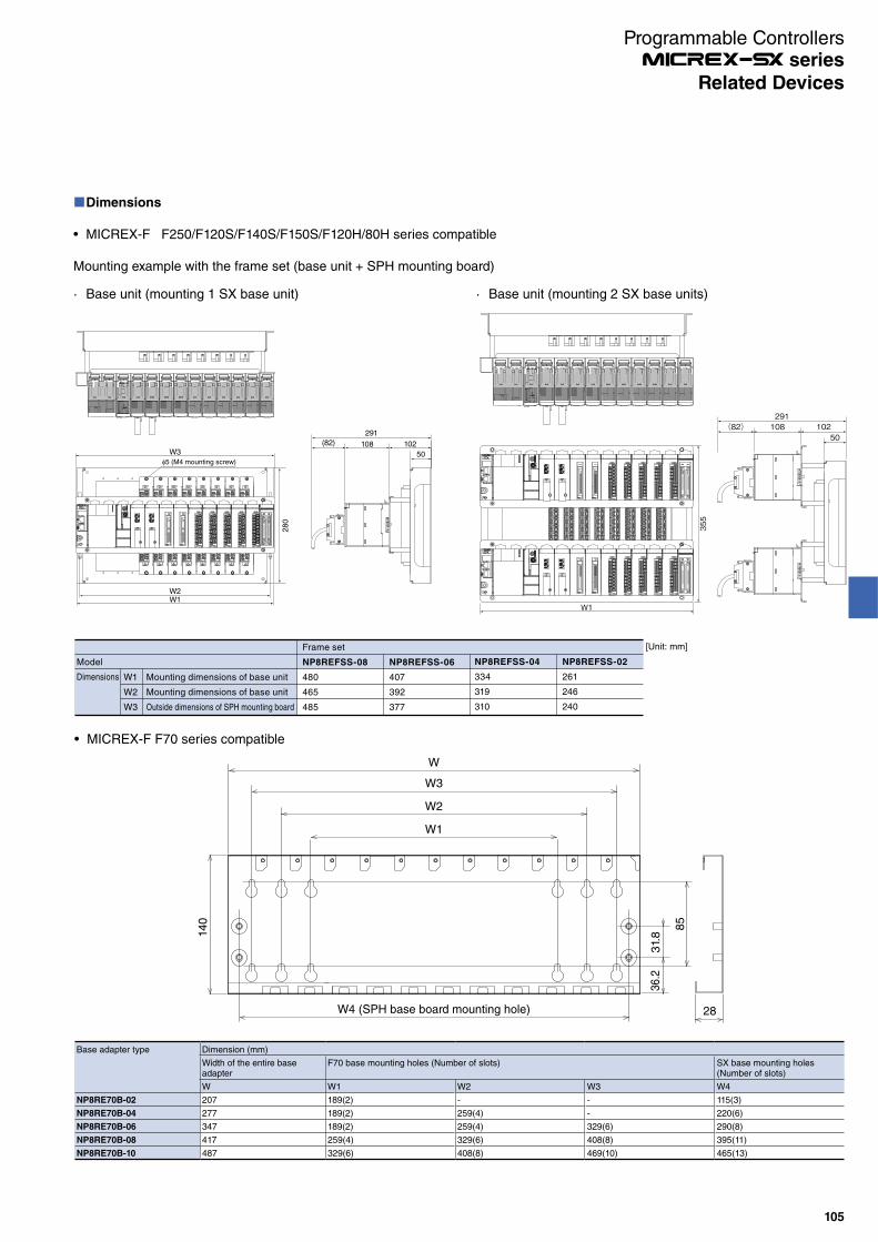
W1
W2
W3
Dimensions
Model
Mounting dimensions of base unit
Mounting dimensions of base unit
Outside dimensions of SPH mounting board
Frame set
NP8REFSS-08
480
465
485
NP8REFSS-06
407
392
377
NP8REFSS-04
334
319
310
NP8REFSS-02
261
246
240
[Unit: mm]
Dimensions
MICREX-F F250/F120S/F140S/F150S/F120H/80H series compatible
Mounting example with the frame set (base unit + SPH mounting board)
· Base unit (mounting 1 SX base unit)
oNL
ERR
oNL
ERRERR
oNL
15
6 7
10 11 12 13
2 3 54
148
0
ERR
oNL
9
1
8 9 10 11
0 21 3
ERR
oNL5
13
431 20
12111098
76
1514 14
4 5
1312
76
15
oNL
ERR
31 20
1098 1115
7
12
4
13
5 6
14 1214 15
6 7
8 9 10 11 12
0 21 3 4
ERR
oNL
13
5 oNL
ERR
5
13
431 20
12111098
6
14 8 9 10 11
0 21 3 4
ERR
oNL7
15
764 5
1514131214 15
6 7
13
5 1 20oNL
1098ERR
3
11
W3
28
0
W1W2
108
291
(82) 102
505 (M4 mounting screw)
· Base unit (mounting 2 SX base units)
355
W1
oNL
ERR
oNL
ERRERR
oNL
15
6 7
10 11 12 13
2 3 54
148
0
ERR
oNL
9
1 5
13
431 20
12111098
76
1514 8 9 10 11
0 21 3
ERR
oNL
14
4 5
1312
76
15
oNL
ERR
31 20
1098 1115
7
12
4
13
5 6
14 14 15
6 7
8 9 10 11 12
0 21 3 4
ERR
oNL
13
5
12
oNL
ERR
5
13
431 20
12111098
6
14 8 9 10
0 21
ERR
oNL7
15 11
3 4 4
12
765
15141314 15
6 7
13
5 1 20oNL
1098ERR
3
11
oNL
ERR
oNL
ERRERR
oNL
15
6 7
10 11 12 13
2 3 54
148
0
ERR
oNL
9
1
8 9 10 11
0 21 3
ERR
oNL5
13
431 20
12111098
76
1514 14
4 5
1312
76
15
oNL
ERR
31 20
1098 1115
7
12
4
13
5 6
14 1214 15
6 7
8 9 10 11 12
0 21 3 4
ERR
oNL
13
5 oNL
ERR
5
13
431 20
12111098
6
14 8 9 10
0 21
ERR
oNL7
15 11
3 4 4
12
765
15141314 15
6 7
13
5 1 20oNL
1098ERR
3
11
291(82) 108 102
50
Base adapter type Dimension (mm)
Width of the entire base adapter
F70 base mounting holes (Number of slots) SX base mounting holes (Number of slots)
W W1 W2 W3 W4
NP8RE70B-02 207 189(2) - - 115(3)
NP8RE70B-04 277 189(2) 259(4) - 220(6)
NP8RE70B-06 347 189(2) 259(4) 329(6) 290(8)
NP8RE70B-08 417 259(4) 329(6) 408(8) 395(11)
NP8RE70B-10 487 329(6) 408(8) 469(10) 465(13)
MICREX-F F70 series compatible
W
140
W4 (SPH base board mounting hole)
31.
83
6.2
85
28
W2
W3
W1
Programmable Controllers series
105
Related Devices

Base adapter type Dimensions (mm)
W H D
NP8RENJB-03 250 140 28.6
NP8RENJB-05 326 140 28.6
NP8RENJB-08 439 140 28.6
NP8RENJB-08L 485 140 28.6
FLEX-PC NJ series compatible
W
14
0
W4 (SPH base board mounting hole)
31.
836.2
85
28
Base adapter type Dimension (mm)
W H D
NP8RE55B-04 262 140 28
NP8RE55B-06 322 140 28
NP8RE55B-08 417 140 28
NP8RE55B-08L 487 140 28
MICREX-F F55 series compatible
290: For mounting NP1BS-08* 28
10
20.4
31.
8
85
140
36.2
322
(27.
5) 250: For mounting NV1P-04*
27.
5
(36)36
16
310: For mounting NV1P-06* (6)6
28220: For mounting NP1BS-06*
31.
8
10
85
14
0
36
.2262
(27.
5)
250: For mounting NV1P-04*
27.
5
(6) 20.46
21
Programmable Controllers series
106
Related Devices

Programmable Controllers series
107
Specifications
Input specificationsItem Specifications
Model NP8SX-113 NP8X-120 NP8X-155 NP8X-165
No. of input points (Common configuration)
16 points (8 points/common 2 circuits) 32 points (16 points/common 2 circuits)
Rated voltage 12 to 24 V DC/AC 12 to 24 V DC/AC 100/120 V AC 200/240 V AC
Max. allowed voltage 30 V DC 26.4 V DC/AC 132 V AC 264 V AC
Input format No polarity No polarity AC input
Rated current 4mA (at 12 V DC), 10mA (at 24 V DC) 4mA (at 12 V DC), 10mA (at 24 V DC) 10mA(at 100 V AC, 50Hz)
10mA(at 200 V AC, 50Hz)
Input impedance 2.2kΩ 2.2kΩ 10kΩ (50Hz),9kΩ (60Hz)
22kΩ (50Hz),18kΩ (60Hz)
Standard operation range
OFF to ON 9.6 to 30 V 9.6 to 26.4 V 80 to 132 V 16 to 264 V
ON to OFF 0 to 5.5 V 0 to 35 V 0 to 70 V
Input delay time OFF to ON 3 ±1.5 ms (hard filter time) + (soft filter time)The soft filter time can be changed in the parameter settings.(OFF to ON) - (ON to OFF): None (default), 0.1-0.1 ms,1-1 ms, 3-3 ms, 3-10 ms, 10-10 ms, 30-30 ms, 100-100 ms
10 ms (hard filter time) + (soft filter time)The soft filter time can be changed in the parameter settings.(OFF to ON) - (ON to OFF): None (default), 0.1-0.1 ms,1-1 ms, 3-3 ms, 3-10 ms, 10-10 ms, 30-30 ms, 100-100 ms
10 ms or less
ON to OFF
Insulation method Photocoupler insulation
Internal current consumption 24 V DC, 40mA or less (all points ON) 24 V DC, 70mA or less (all points ON) 24 V DC, 50mA or less (all points ON)
Depth Low-profile model Standard model
Weight Approx. 220 g (not including terminal block) Approx. 500 g (not including terminal block) Approx. 550 g (not including terminal block)
Output specificationsItem Specifications
Model NP8Y-266 NP8Y-250 NP8Y-263 NP8SY-263
No. of output points (Common configuration)
32 points (8 points/common 4 circuits) 16 points (8 points/common 2 circuits) 16 points (all points are independent)
Output format Relay output Triac output Relay output
Rated voltage 240 V AC, 24 V DC 100 to 240 V AC 240 V AC, 24 V DC
Voltage tolerance 264 V AC or less, 30 V DC or less 85 to 264 V AC 264 V AC or less, 30 V DC or less
Max. load current 264 V AC: 1A/point, 5A/common30 V DC: 1A/point, 5A/common
2A/point, 5A/common 264 V AC: 2A/point30 V DC: 2A/point
Output delay time OFF to ON 10 ms or less (30 V DC) 1 ms or less 10 ms or less (30 V DC)
ON to OFF 10 ms or less (30 V DC) 10 ms or less 10 ms or less (30 V DC)
Leakage current when OFF 0.1mA or less (at 200 V AC/60 Hz) 1mA or less (at 200 V AC/60 Hz) 0.1mA or less (at 200 V AC/60 Hz)
Surge suppressor circuit Varistor CR absorber + varistor Varistor
Maximum opening/closing frequency
1800 times/hour 3600 times/hour
Insulation method Relay insulation, photocoupler insulation
Photocoupler insulation Relay insulation, photocoupler insulation
Internal current consumption 24 V DC, 120mA or less (all points ON) 24 V DC, 50mA or less (all points ON)
No. of occupied words SX bus direct connection: 2 wordsRemote I/O link: 2 words
SX bus direct connection: 2 wordsRemote I/O link: 1 word
SX bus direct connection: 2 wordsRemote I/O link: 2 words
Depth Standard model Low-profile model
Weight Approx. 630 g (not including terminal block)
Approx. 620 g (not including terminal block)
Approx. 500 g (not including terminal block)
Approx. 340 g (not including terminal block)
MICREX-F Size I/O Module (Renewal Tool): NP8 -
Outline
This module is an I/O module with a size equivalent to MICREX-F series FTU module. This renewal tool makes the MICREX-F F120-150S series I/O wirings usable with MICREX-SX series units as they are.
Easy module replacement and signal checkThe module placed on the front allows you to check signals regularly and to quickly replace the module in an emergency.Can be used as an extension unit in MICREX-F series systemThis module has a function allowing to logically change the bit order of terminal block signal wiring. MICREX-F processor modules can be replaced in T-link extension unit as they are.
Features
No control panel modification is requiredThe dimensions of the base board mounting hole for the control panel are the same as those of the M/F series base board. Also, the depth length is minimized.No wiring change is requiredThe same terminal block as one of the MICREX series FTU module is used, so the existing terminal block of the MICREX series can be connected as it is. Also, the electrical performance is inherited from the MICREX-F series.
Related Devices

Programmable Controllers series
108
Analog input specificationsItem Specifications
Model NP8AX-340MR NP8AX-344
Input channel 8 channels
Analog input range 0 to 5 V 0 to 10 V -5 V to +5 V -10 V to +10 V 0 to 20mA
Digital output value 0 to 4000 -2000 to 2000 0 to 4000
Digital output model BCD 4 digits with ± sign/BIN switching
Resolution 12 bits
No. of occupied words 8 words (input)
Overall accuracy ±0.2% (0 to 55 °C) ±0.3% (0 to 55 °C)
Response time 12 ms or less/8 points + tact cycle (ms)
Internal current consumption
24 V DC, 40mA
External terminal Detachable terminal block (M3.5, 20 poles)
Depth Standard model
Weight Approx. 500 g or less (not including terminal block)
Mounting dimensions of base board
Type External dimension (W x H x D) [mm] Weight [g] Base board for SX Fixing screw mounting space (W x H) [mm]
NP8B-13 508 x 260 x 36 1,500 13 slots 465 x 150Same as FSB128/FSB110H
NP8B-11 438 x 260 x 36 1,300 11 slots 392 x 150 Same as FSB126/FSB088H
NP8B-08 336 x 260 x 36 1,000 8 slots 319 x 150 Same as FSB124/FSB086H
NP8B-06 263 x 260 x 36 800 6 slots 246 x 150Same as FSB084
Related Devices
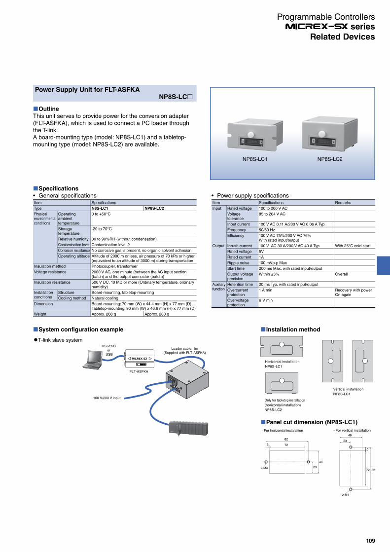
Power Supply Unit for FLT-ASFKANP8S-LC
Outline
This unit serves to provide power for the conversion adapter (FLT-ASFKA), which is used to connect a PC loader through the T-link.A board-mounting type (model: NP8S-LC1) and a tabletop-mounting type (model: NP8S-LC2) are available.
Specifications
General specificationsItem Specifications
Type N8S-LC1 NP8S-LC2
Physical environmental conditions
Operating ambienttemperature
0 to +50°C
Storage temperature
-20 to 70°C
Relative humidity 30 to 90%RH (without condensation)
Contamination level Contamination level 2
Corrosion resistance No corrosive gas is present, no organic solvent adhesion
Operating altitude Altitude of 2000 m or less, air pressure of 70 kPa or higher (equivalent to an altitude of 3000 m) during transportation
Insulation method Photocoupler, transformer
Voltage resistance 2000 V AC, one minute (between the AC input section (batch) and the output connector (batch))
Insulation resistance 500 V DC, 10 MΩ or more (Ordinary temperature, ordinary humidity)
Installation conditions
Structure Board-mounting, tabletop-mounting
Cooling method Natural cooling
Dimension Board-mounting: 70 mm (W) x 44.4 mm (H) x 77 mm (D)Tabletop-mounting: 90 mm (W) x 46.6 mm (H) x 77 mm (D)
Weight Approx. 288 g Approx. 280 g
Power supply specificationsItem Specifications Remarks
Input Rated voltage 100 to 200 V AC
Voltage tolerance
85 to 264 V AC
Input current 100 V AC 0.11 A/200 V AC 0.06 A Typ
Frequency 50/60 Hz
Efficiency 100 V AC 75%/200 V AC 76%With rated input/output
Output Inrush current 100 V AC 30 A/200 V AC 40 A Typ With 25°C cold start
Rated voltage 5V
Rated current 1A
Ripple noise 100 mVp-p Max
Start time 200 ms Max, with rated input/output
Output voltage precision
Within ±5% Overall
Auxiliary function
Retention time 20 ms Typ, with rated input/output
Overcurrent protection
1 A min Recovery with power On again
Overvoltage protection
6 V min
System configuration example
RS-232Cor
USB
Loader cable: 1m(Supplied with FLT-ASFKA)
100 V/200 V input
FLT-ASFKA
T-link slave system
Installation method
Vertical installation
NP8S-LC1
Horizontal installation
NP8S-LC1
Only for tabletop installation
(horizontal installation)
NP8S-LC2
Panel cut dimension (NP8S-LC1)
- For horizontal installation - For vertical installation
82
23
46
725
2-M4
2-M4
23
5
72 82
46
NP8S-LC1 NP8S-LC2
Programmable Controllers series
109
Related Devices
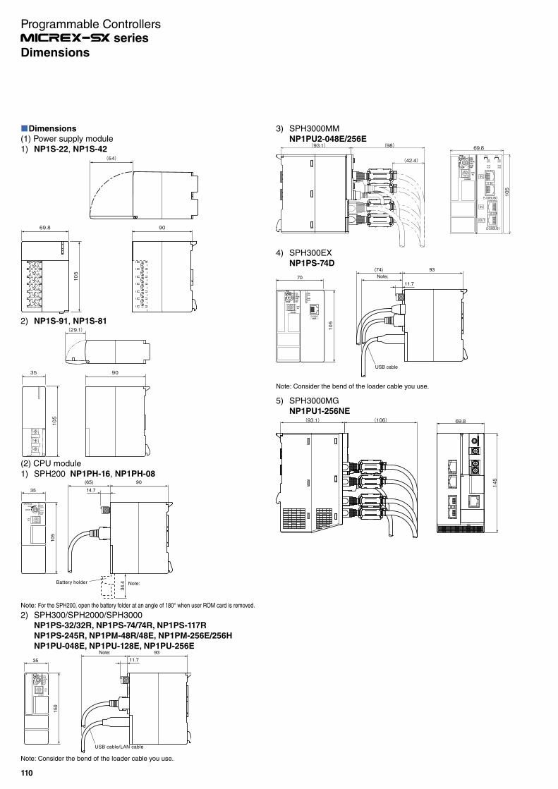
Dimensions
(1) Power supply module
1) NP1S-22, NP1S-42
9069.8
105
(64)
2) NP1S-91, NP1S-81
(2) CPU module
1) SPH200 NP1PH-16, NP1PH-08
4
C
7
65
8
A9
B1
32
0DEF
ERRONL
ALMBAT
RUNSTOP
No.CPU
NP1PH-16RUN
TERM
Note:Battery holder
90(65)
35
10
5
14.7
34
.4
Note: For the SPH200, open the battery folder at an angle of 180° when user ROM card is removed.
2) SPH300/SPH2000/SPH3000
NP1PS-32/32R, NP1PS-74/74R, NP1PS-117R
NP1PS-245R, NP1PM-48R/48E, NP1PM-256E/256H
NP1PU-048E, NP1PU-128E, NP1PU-256E
Note: Consider the bend of the loader cable you use.
3) SPH3000MM
NP1PU2-048E/256E69.8
105
(93.1) (98)
(42.4)
IN
E-SXBUS0
IN
OUT
ONLERR
RUNALM
RUNALM
ONLERR
ES0 ES1
E-SXBUS1
4) SPH300EX
NP1PS-74D93
Note:
(74)
USB cable
70
50
1
11.7
RUN
ALM
EX SX-BUS
OUT
ONL
ERR
32
DE
7
456
98
BCA
1F
0
LOADER
RUN
STOP BAT
No.CPU
UROMERR
ALMRUN
TERMUROM
ONL
Note: Consider the bend of the loader cable you use.
5) SPH3000MG
NP1PU1-256NE69.8
145
(93.1) (106)
9035
501
(29.1)
93Note:
USB cable/LAN cable
35
150
11.7
32
DE
7
456
98
BCA
1F
0
LOADER
RUN
STOP BAT
No.CPU
UROMERR
ALMRUN
TERMUROM
ONL
Programmable Controllers series
110
Dimensions
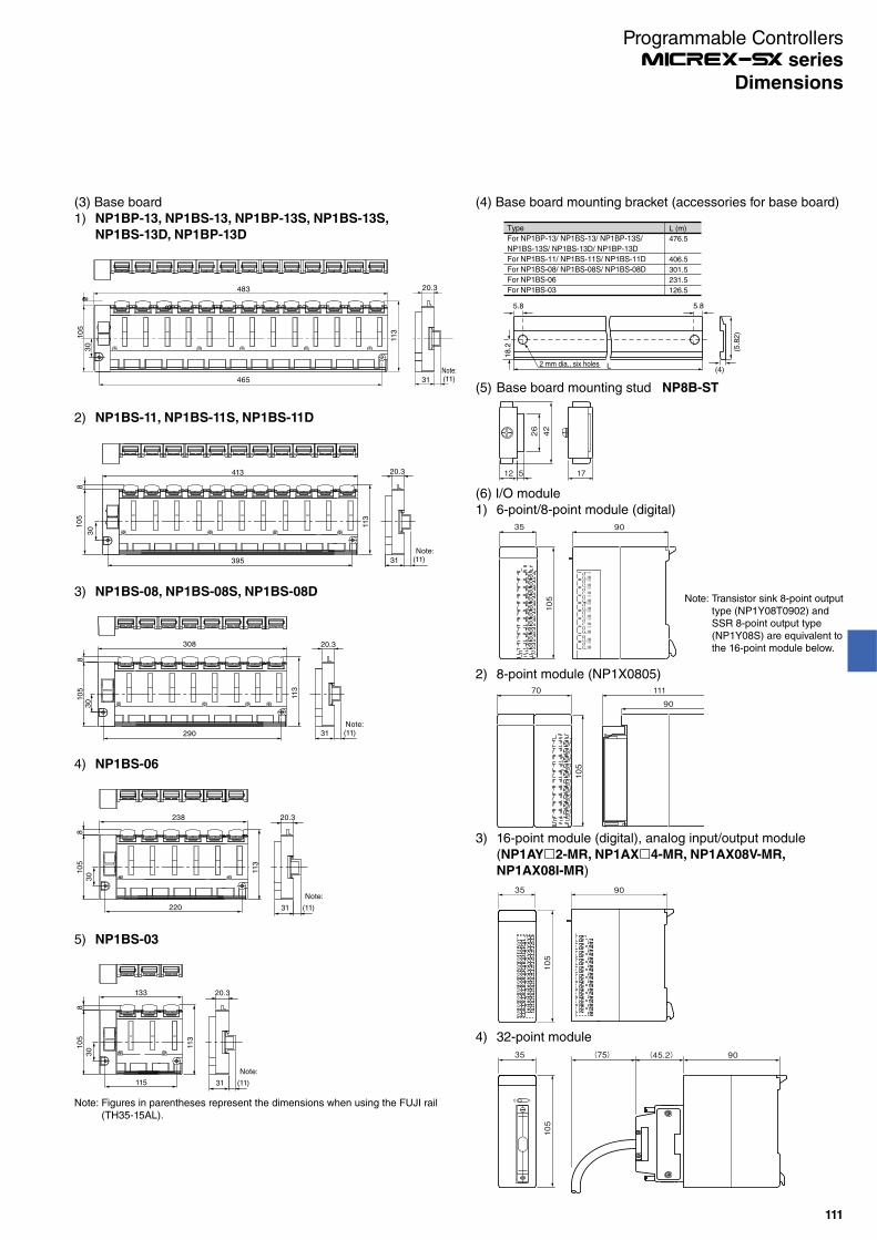
(3) Base board
1) NP1BP-13, NP1BS-13, NP1BP-13S, NP1BS-13S,
NP1BS-13D, NP1BP-13D
8
113
8
30
Note:
20.3
31 (11)
105
465
483
2) NP1BS-11, NP1BS-11S, NP1BS-11D
413 20.3
395 31 (11)
105
113
8
30
Note:
3) NP1BS-08, NP1BS-08S, NP1BS-08D
308 20.3
290
105
830
(11)31
113
Note:
4) NP1BS-06
(11)31
20.3
220
238
105
30
8
113
Note:
5) NP1BS-03
(11)31
20.3
115
133
105
30
8
113
Note:
Note: Figures in parentheses represent the dimensions when using the FUJI rail (TH35-15AL).
3) 16-point module (digital), analog input/output module
(NP1AY 2-MR, NP1AX 4-MR, NP1AX08V-MR,
NP1AX08I-MR)
9035
105
4) 32-point module
105
35 (75) (45.2) 90
0 1
(6) I/O module
1) 6-point/8-point module (digital)90
105
35
Note: Transistor sink 8-point output type (NP1Y08T0902) and SSR 8-point output type (NP1Y08S) are equivalent to the 16-point module below.
2) 8-point module (NP1X0805)
90
105
70 111
(5) Base board mounting stud NP8B-ST
12 5 17
4226
(4) Base board mounting bracket (accessories for base board)
(5.8
2)
(4)2 mm dia., six holes
L (m)
476.5
406.5
301.5
231.5
126.5
Type
For NP1BP-13/ NP1BS-13/ NP1BP-13S/
NP1BS-13S/ NP1BS-13D/ NP1BP-13D
For NP1BS-11/ NP1BS-11S/ NP1BS-11D
For NP1BS-08/ NP1BS-08S/ NP1BS-08D
For NP1BS-06
For NP1BS-03
L
5.8 5.8
18
.2
Programmable Controllers series
111
Dimensions

5) AS-i master module NP1L-AS2
ONL AUP CM
ERR APF CER
SET
DISPLAY
AS-i+
AS-i-
AS-i+
AS-i-
LG
NP1L-
AS1
35 (19) 90
105
4) T-link master module NP1L-TL1,
T-link slave module NP1L-TS1,
T-link interface module NP1L-RT1,
P-link module NP1L-PL1,
PE-link module NP1L-PE1,
OPCN-1 master module NP1L-JP1,
OPCN-1 slave module, NP1L-JS1,
OPCN-1 interface module NP1L-RJ190(44)35
105
Note: This differs by type, and whether or not connectors and switches exist, but outside dimensions are the same for all types.
General purpose communication module NP1L-RS5
ON
1 2
MODE
SDB
SDACH1
CH1
CH1
No.
CH1TERM1-2-3
CH2
No.
CH2
No.
CH2
RDA
RDB
FG
SG
NP1L-
RS5
SDACH2
SDB
RDB
RDA
SG
FG
cDE
F0
1
B
A9
87
6 5 4 3
2
cDE
F0
1
B
A9
87
6 5 4 3
2
cDE
F0
1
B
A9
87
6 5 4 3
2
9035
105
90(37)(90)35
105Note:
Note: This differs by type, and whether or not connectors and switches exist, but outside dimensions are the same for all types.
3) General purpose communication module NP1L-RS1/2/3/4PROFIBUS-DP master module NP1L-PD1,PROFIBUS-DP slave module NP1L-PS1PROFIBUS-DP interface module NP1L-RP1
(7) Communication module
1) Web module NP1L-WE1Ethernet module NP1L-ET1
ONL
ERR
100M LNK T/R
RS232
10/100
Mbps
NP1L-
WE1
9035
501
Note: This differs by type, and whether or not connectors and switches exist, but outside dimensions are the same for all types.
5) 64-point module
90(45.2)(75)35
105
35
105
11190
6) Terminal block protrusion module
(Resistance thermometer element input module
NP1AXH4-PT, NP1AXH4-TC
Thermo-couple input module NP1AXH4-TC,
NP1AXH8G-TC,
Analog input/output moduleNP1AXH8 -MR,
NP1AXH8 G-MR, NP1AYH8 -MR, NP1AYH4 G-MR,
NP1AYH4 -MR, NP1AWH6-MR),Distributor module NP1AXH4DG-MR,
Flow meter F/AD conversion module NP1F-PI4
90
105
34.8(106)
ERR
ONL OUT
SETTING
-MRAYH8VHRNP1
OREADY
QCGND
ONOROP
READYAGCH8CH7
CH5
AGCH6
CH4AG
AGCH3
CH1CH2
PCGND
STANDBY
7) Duplex analog output moduleNP1AYH8VHR-MR
2) Web memory module NP1L-WS1
Programmable Controllers series
112
Dimensions

6) FL-net (OPCN-2) module NP1L-FL39035
105
Note:
UTP
ONL RUN LNK
RXTXERR PER
100M
Note: For AUI and UTP cables, you need to take connector dimensions and cable bend into consideration. (For bend radius, check the specification for the cable you use.)
35
105
12.8 90
8) LONWORKS interface module NP1L-LW1
7) DeviceNet master module NP1L-DN1,
DeviceNet slave module NP1L-DS1,
DeviceNet interface module NP1L-RD1
35
105
(20) 90
9) S-LINK master module NP1L-SL1
ADRS
NP1L-
SL1
DEF.
I/O
SIZE
ON
1
2
0V
24V
D
G
0V
24V
SET
A
B
D
G
0V
24V
42 3
ONL
ERR SER1
SEND
0
8
6
23
45
197
9035
105
(34)
10) LE-net module NP1L-LE1
12
43
LNK
ALMERR
ONL
DCB EA
9
435
7
6 2
8
F0
1
IN OUT
4 1
23
56
09
87
87
65
23
4
09
1
9035
105
Note:
11.2
Note: Consider the bend of the cable you use.
ALMERR
OUTLNKONL IN
3
D
7
6 5 4
8
A
9
BC
12
F0
E
8
24
3
7
65
10
9
8
24
3
7
65
10
9
9035
105
(min. 75)
11) LE-net loop2 module NP1L-LL2
12) Remote terminal master/slave module NP1L-RM1
9035
105
ONL
ERR
NP1LRM1
TER RER
DC24V
R
Signal+
Signal-
DC24V+
DC24V-
FG
T/R
SER
(10)
13) SX bus optical link module NP1L-OL1
(min. 83)35 90
10
5
16.5
63
.5
Radius of curvature
50 mm
or more
14) SX bus optical link converter
6 mm dia., M4 screw Fixation
85
10
95
29.8
48.3
40
(min. 83) 95
Radius of curvature
50 mm
or more
NP2L-OE1
105
35 90
61.35
13.5
(92)
OPT ERR
ONL
NP1L- OL2
NP2L-OE2
Programmable Controllers series
113
Dimensions
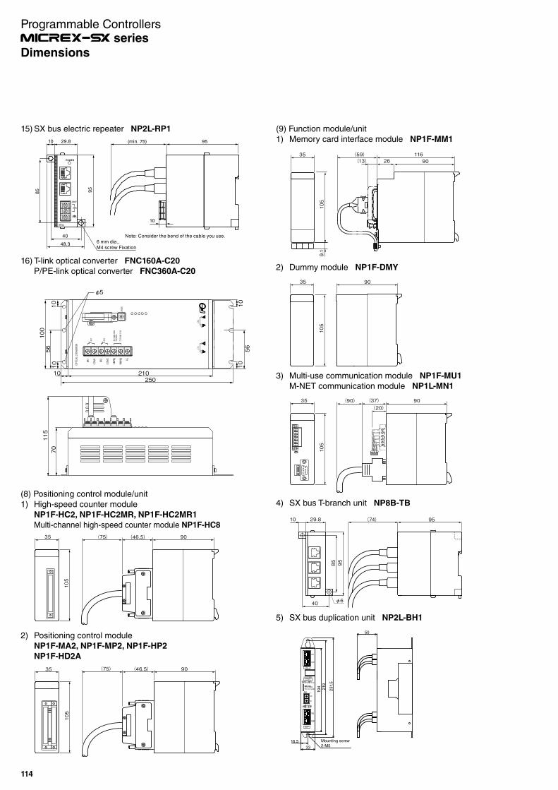
(9) Function module/unit
1) Memory card interface module NP1F-MM1
9.1
105
35 (59)26
11690(13)
2) Dummy module NP1F-DMY
9035
105
3) Multi-use communication module NP1F-MU1
M-NET communication module NP1L-MN1
(20)90(37)(90)35
105
5) SX bus duplication unit NP2L-BH1
0F
DE
321 8
CBA
9
45 67
10
F
DE
32 7
C
8
B
9
A
45 6
219
231.
5
Mounting screw2-M5
194
50
33
16.5
4) SX bus T-branch unit NP8B-TB
29.8 (74) 95
40
85 95
10
φ6
(8) Positioning control module/unit
1) High-speed counter module
NP1F-HC2, NP1F-HC2MR, NP1F-HC2MR1
Multi-channel high-speed counter module NP1F-HC8
90(46.5)(75)35
105
2) Positioning control module
NP1F-MA2, NP1F-MP2, NP1F-HP2
NP1F-HD2A
90(46.5)(75)35
105
16) T-link optical converter FNC160A-C20
P/PE-link optical converter FNC360A-C20
43
210
56789A
BCD E
F
LiPj
NiNj
FGBR1
BR2
COM1
COM2
OPTICA
L CON
VERT
ER
CH1
CH2
INOU
TIN
OUT
MOD
E
BR1
BR2
50/60H
zAC
100`240V
DC100`110V
5610
10
100
56
210
φ5
250
70115
1010
10
15) SX bus electric repeater NP2L-RP1
6 mm dia., M4 screw Fixation
85
10
48.3
29.8 (min. 75)
Note: Consider the bend of the cable you use.
95
40
95
10
POWER
NP2L-
24 V
Programmable Controllers series
114
Dimensions
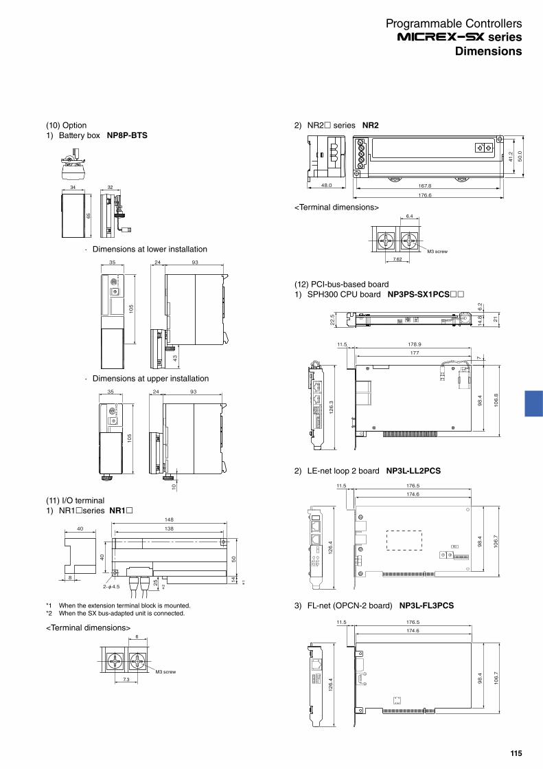
167.8
176.6
41.2
50.0
48.0
<Terminal dimensions>
7.62
6.4
M3 screw
2) NR2 series NR2
*1 When the extension terminal block is mounted.*2 When the SX bus-adapted unit is connected.
148
40
40
50
14
*1
25*2
8
2-φ4.5
138
<Terminal dimensions>
7.3
6
M3 screw
(11) I/O terminal
1) NR1 series NR1
(10) Option
1) Battery box NP8P-BTS
65
34 32
9335 24
105
43
9335 24
105
10
· Dimensions at lower installation
· Dimensions at upper installation
(12) PCI-bus-based board
1) SPH300 CPU board NP3PS-SX1PCS
126.3
11.5 178.9
177
106.8
98.4
21
22.5
6.2
714.8
2) LE-net loop 2 board NP3L-LL2PCS
106.7
98.4
11.5 176.5
174.6
126.4
3) FL-net (OPCN-2 board) NP3L-FL3PCS
RUNPERLNKTXRX 10
6.7
98.4
11.5 176.5
174.6
126.4
Programmable Controllers series
115
Dimensions

(13) E-SX bus based
1) Digital I/O unit NU2X3206-W/ NU2Y32T09P6
240
60
65∅4.5
230
55
4.5
6.5
(69)
2) Analog input/output unit NU2AXH2-MR/NU2AYH2V-MR
∅4.5
4.5
6.5
60(69)155165
5565
3) Auxiliary power supply unit NU2V-PA1
6 mm dia.,(M4 screw fixing)
10 29.8
85
40
95
10NU2V-
24 V
OCP_RST
Power
(min: 101)
(min: 42.4)
E-S
X B
US
PA1
E-S
X B
US
Pow
erO
ut
Programmable Controllers series
116
(14) MF size I/O module
NP8X-120/155/165/NP8Y-250/263/266/NP8AX-340MR/344
Dimensions
NP8SX-113/NPSSY-263
35 68
92
(22)
255
34 28 116
255

Type/Ordering codes
Product name Model Specifications and namesOrdering code
Standards
CE UL LR NK
*2 cUL *3
CPUmodule
SPH3000MG NP1PU1-256NE Program memory capacity 256K stepsUser ROM/USB/Ethernet/SX-Net adapted, Max. No. of I/O Points: 73728
Accessories: Data backup battery (Built-in)SX bus terminating plug 2 piecesScrewdriver (for the CPU setting)
Basic instructionProcessing speed6 ns –
NP1PU1-256NE
SPH3000MM NP1PU2-048E Program memory capacity 48K steps x 2User ROM/USB/Ethernet adapted, Max. No. of I/O Points: 139264
Basic instructionProcessing speed9 ns –
NP1PU2-048E
NP1PU2-256E Program memory capacity 256K steps x 2 NP1PU2-256E User ROM/USB/Ethernet adapted, Max. No. of I/O Points: 139264
E-SX bus extension cable*1
NU1C-P3 300 mm cable NU1C-P3 -
NU1C-P6 600 mm cable NU1C-P6 -
NU1C-P8 800 mm cable NU1C-P8 -
NU1C-02 2,000 mm cable NU1C-02 -
NU1C-05 5,000 mm cable NU1C-05 -NU1C-10 10,000mm cable NU1C-10 -NU1C-15 15,000mm cable NU1C-15 -NU1C-25 25,000mm cable NU1C-25 -NU1C-50 50,000mm cable NU1C-50 -NU1C-A0 100,000mm cable NU1C-A0 -
Communication module NP1L-RU1 E-SX bus integrated type interface module NP1L-RU1 E-SX busSeparate placement unit
NU2X3206-W 24 V DC, 32 points, 7 mA, 0 to 100 ms variable Screw terminal NU2X3206-W NU2Y32T09P6 Transistor sink , 12 to 24 V DC, 32 points, 0.6 A/point, 4 A/common Screw terminal NU2Y32T09P6 NU2AXH2-MR High-speed multiple-range input 2 ch, resolution: 15 bits, 25 μs conversion period Screw terminal NU2AXH2-MR NU2AYH2V-MR High-speed multiple-range output 2 ch, resolution: 15 bits (voltage), 25 μs conversion period Screw terminal NU2AYH2V-MR NU2F-HC2 High-speed counter unit, 4 Mbps (line driver), 1 Mbps (open collector 5 V/12 V/24 V DC) NU2F-HC2 NU2V-PA1 Auxiliary power unit E-SX bus built-in 24 V DC power supply NU2V-PA1
ROM card NP8PSD-002 User ROM card SD memory card for SPH3000/SPH3000 MM/SPH3000MG, Capacity 2 GB NP8PSD-002 - - - -
SPH3000MG/SPH3000MM E-SX bus product
Product name Model Specifications and namesOrdering code
StandardsCE UL LR NK*2 cUL *3
CPUmodule
SPH200 NP1PH-08 Program memory capacity 8K steps Accessories:Memory backup battery (built-in) SX bus terminating plug 2 piecesScrewdriver (for the CPU setting)
Basic instructionProcessing speed70 ns –
NP1PH-08 Max. number of I/O points: 8192 points
NP1PH-16 Program memory capacity 16K steps NP1PH-16 Max. number of I/O points: 8192 points
SPH300 NP1PS-32 Program memory capacity 32K steps Basic instructionProcessing speed20 ns –
NP1PS-32 Max. number of I/O points: 8192 points
NP1PS-32R Program memory capacity 32K steps NP1PS-32R User ROM/USB adapted, Max. No. of I/O points: 8192 points
NP1PS-74R Program memory capacity 74K steps NP1PS-74R User ROM/USB adapted, Max. No. of I/O points: 8192 points
NP1PS-117R Program memory capacity 117K steps NP1PS-117R User ROM/USB adapted, Max. No. of I/O points: 8192 points
NP1PS-245R Program memory capacity 245K steps NP1PS-245R User ROM/USB adapted, Max. No. of I/O points: 8192 points
SPH300EX NP1PS-74D Program memory capacity 74K steps x 2 NP1PS-74D User ROM/USB adapted, Max. No. of I/O points: 8192 points x 2
SPH2000 NP1PM-48R Program memory capacity 48K steps Basic instructionProcessing speed30 ns –
NP1PM-48R User ROM/USB adapted, Max. No. of I/O points: 8192 points
NP1PM-48E Program memory capacity 48K steps NP1PM-48E User ROM/USB/Ethernet adapted, Max. No. of I/O Points: 8192
NP1PM-256E Program memory capacity 256K steps NP1PM-256E User ROM/USB/Ethernet adapted, Max. No. of I/O Points: 8192
NP1PM-256H Program memory capacity 256K steps, redundancy function supported NP1PM-256H User ROM/USB adapted, Max. No. of I/O points: 8192 points
SPH3000 NP1PU-048E Program memory capacity 48K steps Basic instructionProcessing speed9 ns –
NP1PU-048E User ROM/USB/Ethernet adapted, Max. No. of I/O Points: 8192
NP1PU-128E Program memory capacity 128K steps NP1PU-128EUser ROM/USB/Ethernet adapted, Max. No. of I/O Points: 8192
NP1PU-256E Program memory capacity 256K steps NP1PU-256E User ROM/USB/Ethernet adapted, Max. No. of I/O Points: 8192
SPH3000D NP1PU-048EZM SPH3000 program memory capacity 48K steps NP1PU-048EUser ROM/USB/Ethernet adapted, Max. No. of I/O points: 8,192
NP1PU-096EZM SPH3000 program memory capacity 128K steps NP1PU-128EUser ROM/USB/Ethernet adapted, Max. No. of I/O points: 8,192
NP1PU-128EZM SPH3000 program memory capacity 128K steps NP1PU-128EUser ROM/USB/Ethernet adapted, Max. No. of I/O points: 8,192
NP1PU-256EZM SPH3000 program memory capacity 256K steps NP1PU-256EUser ROM/USB/Ethernet adapted, Max. No. of I/O points: 8,192
Power supply module NP1S-22 Input: 100 to 120 V/ 200 to 240 V AC Output: 35 W Accessories: ALM contact connector, line voltage switching short bar NP1S-22 NP1S-91 Input: 100 to 120 V AC Output: 15 W (1 slot) NP1S-91 NP1S-81 Input: 200 to 240 V AC Output: 15 W (1 slot) NP1S-81 NP1S-42 Input: 24 V DC Output: 15 Accessories: ALM contact connector NP1S-42
Base board NP1BS-03 For 3 slots Processor buses 2 slots Accessories:Base boardMounting bracket
NP1BS-03 NP1BS-06 For 6 slots Processor buses 4 slots NP1BS-06 NP1BS-08 For 8 slots Processor buses 3 slots NP1BS-08 NP1BS-11 For 11 slots Processor buses 3 slots NP1BS-11 NP1BS-13 For 13 slots Processor buses 3 slots NP1BS-13
*1 Any length of cable is applicable. Contact our sales representatives for details.*2 The compliance with the CE marking is confirmed for a single unit in the SX series. Be sure to check the compliance with the standard of the final product in which the SX series is built.*3 To prevent the vibration, the module must be fixed for each of the base boards.*4 The model NPS-22 A is UL-certified (cUL certification is not obtained).*5 The model NP1S-91 A is UL-Recognition-certified (cUL certification is not obtained).*6 The model NP1S-81 A is UL-Recognition-certified (cUL certification is not obtained).*7 There is no cUL certification.
*4
*5
*6
SPH product
*7
Applicable - Not applicable
Programmable Controllers series
117
Ordering Information

Product name Model Specifications and names Ordering code
Standards
CE UL LR NK
*2 cUL *3
Base board NP1BP-13 For 13 slots Processor buses 10 slots Accessories:Base board mountingbracket
NP1BP-13 NP1BS-08S Base board with station number setting switch, for 8 slots processor buses 3 slots NP1BS-08S NP1BS-11S Base board with station number setting switch, for 11 slots processor buses 3 slots NP1BS-11S NP1BS-13S Base board with station number setting switch, for 13 slots processor buses 3 slots NP1BS-13S NP1BP-13S Base board with station number setting switch, for 13 slots processor buses 10 slots NP1BP-13S NP1BS-08D Hot plug base board with station number setting switch, for 8 slots processor buses 3 slots NP1BS-08D NP1BS-11D High-performance hot plug base board with station number setting switch, for 11 slots processor buses 3 slots NP1BS-11D NP1BS-13D Hot plug base board with station number setting switch, for 13 slots processor buses 3 slots NP1BS-13D NP1BP-13D High-performance hot plug base board with station number setting switch, for 13 slots processor buses 10 slots NP1BP-13D
SX bus extension cable*1
NP1C-P3 300 mm cable NP1C-P3 - NP1C-P6 600 mm cable NP1C-P6 - NP1C-P8 800 mm cable NP1C-P8 - NP1C-02 2,000 mm cable NP1C-02 - NP1C-05 5,000 mm cable NP1C-05 - NP1C-10 10,000 mm cable NP1C-10 - NP1C-15 15,000 mm cable NP1C-15 -
NP1C-25 25,000 mm cable NP1C-25 - SX bus T-branch unit NP8B-TB SX bus T-branch connecting unit, Accessories: SX bus terminating plug 1 piece NP8B-TB Digital input module*8
NP1X1606-W 24 V DC, 16 points, 7 mA, 1 to 100 ms variable Screw terminal NP1X1606-W NP1X3206-W 24 V DC, 32 points, 4 mA, 1 to 100 ms variable, optional connector Connector NP1X3206-W NP1X3202-W 5/12 V DC, 32 points, 3/9 mA, 1 to 100 ms variable, optional connector Connector NP1X3202-W NP1X3206-A 24 V DC, 32 points, 4 mA, 0.1 to 100 ms variable, pulse catch 20 kHz, optional connector Connector NP1X3206-A NP1X6406-W 24 V DC, 64 points, 4 mA, 1 to 100 ms variable, optional connector Connector NP1X6406-W NP1X1607-W 48 V DC, 16 points, 5 mA, 1 to 100 ms variable Screw terminal NP1X1607-W NP1X0805 110 V DC, 8 points, 5 mA, 1 to 100 ms variable Screw terminal NP1X0805
NP1X0810 100 to 120 V AC, 8 points, 10 mA, 10 ms Screw terminal NP1X0810 NP1X1610 100 to 120 V AC, 16 points, 10 mA, 10 ms Screw terminal NP1X1610 NP1X0811 200 to 240 V AC, 8 points, 10 mA, 10 ms Screw terminal NP1X0811 NP1X1610-RI 100 to 120 V AC, 16 points, 7 mA, 10 ms Screw terminal NP1X1610-RI NP1X1611-RI 200 to 240 V AC, 16 points, 7 mA, 10 ms Screw terminal NP1X1611-RI
Digital output module*8
NP1Y08T0902 Transistor sink , 12 to 24 V DC, 8 points, 2.4 A/point, 8 A/common Screw terminal NP1Y08T0902 NP1Y16T09P6 Transistor sink , 12 to 24 V DC, 16 points, 0.6 A/point, 4 A/common Screw terminal NP1Y16T09P6 NP1Y32T09P1-A Transistor sink , 24 V DC, 32 points, 0.12 A/point, 3.2 A/common Connector NP1Y32T09P1-A
Pulse train output 20 kHz x 4 ch (Built-in), optional connector
NP1Y32T09P1 Transistor sink , 12 to 24V DC, 32 points, 0.12 A/point, 3.2 A/common, optional connector Connector NP1Y32T09P1 NP1Y64T09P1 Transistor sink , 12 to 24V DC, 64 points, 0.12 A/point, 3.2 A/common, optional connector Connector NP1Y64T09P1 NP1Y16T10P2 Transistor sink , 48 V DC, 16 points, 0.2 A/point, 1.6 A/common Screw terminal NP1Y16T10P2 NP1Y08U0902 Transistor source, 12 to 24 V DC, 8 points, 2.4 A/point, 8 A/common Screw terminal NP1Y08U0902 NP1Y16U09P6 Transistor source, 12 to 24 V DC, 16 points, 0.6 A/point, 4 A/common Screw terminal NP1Y16U09P6 NP1Y32U09P1 Transistor source, 12 to 24V DC, 32 points, 0.12 A/point, 3.2 A/common, optional connector Connector NP1Y32U09P1 NP1Y64U09P1 Transistor source, 12 to 24V DC, 64 points, 0.12 A/point, 3.2 A/common, optional connector Connector NP1Y64U09P1 NP1Y08S SSR, 100 to 240 V AC, 8 points: all points are independent, 2.2 A/point Screw terminal NP1Y08S NP1Y08R-04 Ry, 110 V DC, 240 V AC, 8 points, 30 V DC/264 V AC: 2.2 A/point, 4 A/common Screw terminal NP1Y08R-04 NP1Y16R-08 Ry, 110 V DC, 240 V AC, 16 points, 30 V DC/264 V AC: 2.2 A/point, 8 A/common Screw terminal NP1Y16R-08 NP1Y08R-00 Ry, 110 V DC, 240 V AC, 8 points, 30 V DC/264 V AC: 2.2 A/point, independent Screw terminal NP1Y08R-00
Digital I/O module*8
NP1W1606T 24 V DC, 8-point source input, 12 to 24 V DC, 8-point Tr sink output Screw terminal NP1W1606T NP1W1606U 24 V DC, 8-point sink input, 12 to 24 V DC, 8-point Tr source output Screw terminal NP1W1606U NP1W3206T 24 V DC, 16-point source input, 12 to 24 V DC Tr sink 16-point output, optional connector Connector NP1W3206T NP1W3206U 24 V DC 16-point sink input, 12 to 24 V DC Tr source 16-point output, optional connector Connector NP1W3206U NP1W6406T 24 V DC, 32-point source input, 12 to 24 V DC Tr sink 32-point output, optional connector Connector NP1W6406T NP1W6406U 24 V DC, 32-point bidirectional input, 12 to 24 V DC Tr source 32-point output, optional connector Connector NP1W6406U
Analog input module NP1AX04-MR Standard type multi-range input 4 ch, resolution: 10 bits Screw terminal NP1AX04-MR NP1AXH4-MR High-speed multi-range input 4 ch, resolution: 14 bits Screw terminal NP1AXH4-MR NP1AX08V-MR Standard type multi-range input 8 ch, resolution: 10 bits (voltage type) Screw terminal NP1AX08V-MR NP1AX08I-MR Standard type multi-range input 8 ch, resolution: 10 bits (current type) Screw terminal NP1AX08I-MR NP1AXH8V-MR High-speed multi-range input 8 ch, resolution: 14 bits (voltage type) Screw terminal NP1AXH8V-MR NP1AXH8I-MR High-speed multi-range input 8 ch, resolution: 14 bits (current type) Screw terminal NP1AXH8I-MR NP1AXH8VG-MR High-speed multi-range input 8 ch, between channels insulated, resolution: 16 bits (voltage type) Screw terminal NP1AXH8VG-MR NP1AXH8IG-MR High-speed multi-range input 8 ch, between channels insulated, resolution: 16 bits (current type) Screw terminal NP1AXH8IG-MR NP1AXH4-PT Resistance thermometer element input (Pt1 00 Ω/JPt 100 Ω) 4 ch Screw terminal NP1AXH4-PT
Accuracy: ±0.3% (ambient temperature: 18 to 28°C), ±0.7% (ambient temperature: 0 to 55°C)
NP1AXH6G-PT High-accuracy resistance thermometer element input (Pt100Ω/JPt100Ω) 6 ch Screw terminal NP1AXH6G-PT Accuracy: ±0.05 to ±0.07% (ambient temperature: 18 to 28°C), ±0.239% (ambient temperature: 0 to 55°C)
NP1AXH4-TC Thermo-couple input module 4 ch Screw terminal NP1AXH4-TC Accuracy: ±0.3% (ambient temperature: 18 to 28°C), ±0.7% (ambient temperature: 0 to 55°C)
NP1AXH8G-TC High-accuracy thermo-couple input module 8 ch Screw terminal NP1AXH8G-TC Accuracy: ±0.05 to ±0.26% (ambient temperature: 18 to 28°C), ±0.3 to ±0.6% (ambient temperature: 0 to 55°C)
NP1AXH4DG-MR Distributor module, 4 ch, between channels high dielectric strength insulated, resolution: 16 bits Screw terminal NP1AXH4DG-MR
Accuracy: ±0.1% of F.S.R. (ambient temperature: 25°C)
Analog output module NP1AY02-MR Standard type multi-range output 2 ch, resolution: 10 bits Screw terminal NP1AY02-MR NP1AYH2-MR High-speed multi-range output 2 ch, resolution: 14 bits Screw terminal NP1AYH2-MR NP1AYH4V-MR High-speed multi-range output 4 ch, resolution: 14 bits (voltage type) Screw terminal NP1AYH4V-MR NP1AYH4I-MR High-speed multi-range output 4 ch, resolution: 14 bits (current type) Screw terminal NP1AYH4I-MR
*8 Connectors (solder type) for digital input, output, I/O mixture and positioning module are separately sold.Applicable connector type: Fujitsu FCN-361J040-AU (connector), FCN-360C040-B (cover), our product type: NP8V-CN
Applicable - Not applicable
Programmable Controllers series
118
Ordering Information
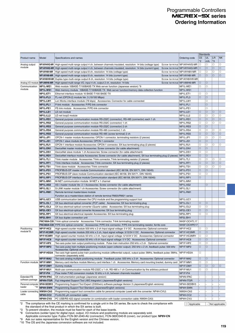
Product name Model Specifications and names Ordering code
Standards
CE UL LR NK
*2 cUL *3
Analog output module
NP1AYH4VG-MR High-speed multi-range output 4 ch, between channels insulated, resolution: 14 bits (voltage type) Screw terminal NP1AYH4VG-MR
NP1AYH4IG-MR High-speed multi-range output 4 ch, between channels insulated, resolution: 14 bits (current type) Screw terminal NP1AYH4IG-MR
NP1AYH8V-MR High-speed multi-range output 8 ch, resolution: 14 bits (voltage type) Screw terminal NP1AYH8V-MR
NP1AYH8I-MR High-speed multi-range output 8 ch, resolution: 14 bits (current type) Screw terminal NP1AYH8I-MR
NP1AYH8VHR-MR Duplex type multi-range output 8 ch, resolution: 14 bits (voltage type) Screw terminal NP1AYH8VHR-MR
Analog I/O module NP1AWH6-MR High-speed multi-range I/O, input 4 ch, output 2 ch, resolution: 14 bits Screw terminal NP1AWH6-MR
Communication module
NP1L-WE1 Web module 10BASE-T/100BASE-TX Web server function (Japanese version) *9 NP1L-WE1
NP1L-WS1 Web memory module 10BASE-T/100BASE-TX Web server function/memory data collection function NP1L-WS1
NP1L-ET1 Ethernet interface module 10 BASE-T/100 BASE-TX NP1L-ET1
NP1L-FL3 FL-net (OPCN-2) module Ver. 3 (10/100 Mbps) NP1L-FL3
NP1L-LW1 Lon Works interface module (78 kbps) Accessories: Connector for cable connected NP1L-LW1
NP1L-PL1 P-link module Accessories: P/PE-link connector NP1L-PL1
NP1L-PE1 PE-link module Accessories: P/PE-link connector NP1L-PE1
NP1L-LE1 LE-net module NP1L-LE1
NP1L-LL2 LE-net loop2 module NP1L-LL2
NP1L-RS1 General purpose communication module RS-232C (connector), RS-485 (connector) each 1 ch NP1L-RS1
NP1L-RS2 General purpose communication module RS-232C (connector) 1 ch NP1L-RS2
NP1L-RS3 General purpose communication module RS-232C (connector) 2 ch NP1L-RS3
NP1L-RS4 General purpose communication module RS-485 (connector) 1 ch NP1L-RS4
NP1L-RS5 General purpose communication module RS-485 (screw terminal) 2 ch NP1L-RS5
NP1L-JP1 OPCN-1 master module Accessories: OPCN-1 connector, terminating resistors (2 pieces) NP1L-JP1
NP1L-JS1 OPCN-1 slave module Accessories: OPCN-1 connector NP1L-JS1
NP1L-RJ1 OPCN-1 interface module Accessories: OPCN-1 connector, SX bus terminating plug (2 pieces) NP1L-RJ1
NP1L-DN1 DeviceNet master module Accessories: Screw connector (for cable attachment) NP1L-DN1
NP1L-DS1 DeviceNet slave module 1 ch Accessories: Screw connector (for cable attachment) NP1L-DS1
NP1L-RD1 DeviceNet interface module Accessories: Screw connector (for cable attachment), SX bus terminating plug (2 pieces) NP1L-RD1
NP1L-TL1 T-link master module Accessories: T-link connector, T-link terminating resistor (2 pieces) NP1L-TL1
NP1L-RT1 T-link interface module Accessories: T-link connector, SX bus terminating plug (2 pieces) NP1L-RT1
NP1L-TS1 T-link slave module Accessories: T-link connector NP1L-TS1
NP1L-PD1 PROFIBUS-DP master module Communication standard (IEC 66158, EN 50171, DIN 19245) NP1L-PD1
NP1L-PS1 PROFIBUS-DP slave module Communication standard (IEC 66158, EN 50171, DIN 19245) NP1L-PS1
NP1L-RP1 PROFIBUS-DP interface module Communication standard (IEC 66158, EN 50171, DIN 19245) NP1L-RP1
NP1L-MN1 M-NET communication module M-NET x 1 channel NP1L-MN1
NP1L-AS2 AS-i master module Ver. 2.1 Accessories: Screw connector (for cable attachment) NP1L-AS2
NP1L-SL1 S-LINK master module 1 ch Accessories: Screw connector (for cable attachment) NP1L-SL1
NP1L-RM1 Remote terminal master/slave module NP1L-RM1
Function as a master/slave station of remote terminal RM20/RM21 series
NP1L-UC1 USB communication between the CPU module and the programming support tool NP1L-UC1
NP1L-OL1 SX bus electrical-optical converter (PCF cable) Accessories: SX bus terminating plug NP1L-OL1
NP1L-OL2 SX bus electrical-optical converter (Quartz cable) Accessories: SX bus terminating plug NP1L-OL2
NP2L-OE1 SX bus electrical-optical converter Accessories: SX bus terminating plug NP2L-OE1
NP2L-RP1 SX bus electrical-electrical repeater Accessories: SX bus terminating plug NP2L-RP1
NP2L-BH1 SX bus duplex connection unit NP2L-BH1
FNC160A-C20 T-link optical converter Accessories: T-link connector, T-link terminating resistor NH5F-OCHTL17
FNC360A-C20 P/PE-link optical converter Accessories: P/PE-link connector, P/PE-link terminating resistor, ferrite core NH5F-OCHPE17
Positioning module*8
NP1F-HC2 High-speed counter module 500 kHz x 2 ch Input signal voltage: 5 V DC Accessories: Optional connector NP1F-HC2
NP1F-HC2MR High-speed counter module 200 kHz x 2 ch, Input signal voltage: 5/12/24 V DC Accessories: Optional connector NP1F-HC2MR
NP1F-HC2MR1 High-speed counter module 50 kHz x 2 ch, Input signal voltage: 5/12/24 V DC Accessories: Optional connector NP1F-HC2MR1
NP1F-HC8 High-speed counter module 50 kHz x 8 ch Input signal voltage: 5 V DC Accessories: Optional connector NP1F-HC8
NP1F-HP2 Two-axis pulse train output positioning module Pulse train instruction 250 kHz x 2 ch Optional connector NP1F-HP2
NP1F-MP2 Two-axis pulse train multiple positioning module (open collector output): 250 kHz x 2 ch, feedback pulse: 500 kHz Accessories: Optional connector
NP1F-MP2
NP1F-HD2A Two-axis high-speed pulse train positioning module (differential output), output pulse: 5MHz, feedback pulse: 5MHz, connector (separately sold)
NP1F-HD2A
NP1F-MA2 Two-axis analog multiple positioning module Feedback pulse: 500 kHz x 2 ch Accessories: Optional connector NP1F-MA2
Function module NP1F-MM1 Memory card interface module Memory card interface 1 ch Accessories: Memory card mounting bracket, dummy card NP1F-MM1
NP1F-DMY Dummy module NP1F-DMY
NP1F-MU1 Multi-use communication module RS-232C x 1 ch, RS-485 x 1 ch Communication by the arbitrary protocol NP1F-MU1
NP1F-PI4 Flow meter F/AD conversion module 10 kHz x 4 ch, between channels insulated NP1F-PI4
Extended FB software package
NP4N-IPAC SX instrumentation package (Japanese version) NP4N-IPAC - - - -
NP4N-ITGR Fuji Integrated Support Tool (@E.Integrator) (Japanese/English versions) NP4N-ITGR - - - -
Personal computer loader *10
NP4H-SEDBV3 Programming Support Tool Expert (D300win) software package Version 3 (Japanese/English versions) NP4H-SEDBV3 - - - -
NP4H-SWN Programming Support Tool Standard (Japanese/English versions) NP4H-SWN - - - -
Loader connecting cable
NW0H-CA3 Programming support tool connection cable for personal computer (used with the converter: NP4H-CVU) NW0H-CA3 - - - -
NP4H-CC2 FUJILOG μK connection cable NP4H-CC2 - - - -
NP4H-CVU PC USB/RS-422 signal converter (in combination with loader connection cable: NW0H-CA3) NP4H-CVU - - -
*2 The compliance with the CE marking is confirmed for a single unit in the SX series. Be sure to check the compliance with the standard of the final product in which the SX series is built.
*3 To prevent vibration, the module must be fixed for each of the base boards.*8 Connectors (solder type) for digital input, output, I/O mixture and positioning module are separately sold.
Applicable connector type: Fujitsu FCN-361J040-AU (connector), FCN-360C040-B (cover), our product type: NP8V-CN*9 Ask our sales representative for the English version and the Chinese version.*10 The OS and the Japanese conversion software are not included.
Applicable - Not applicable
Programmable Controllers series
119
Ordering Information

Product name Model Specifications and names Ordering code
Standards
CE UL LR NK
*2 cUL *3
ROM cassette NP8PMF-16 User ROM cassette for the SPH200, Capacity: 16 MB NP8PMF-16 - - - -
NP8PCF-256 User ROM card compact flash memory for the SPH300/SPH2000, Capacity: 256 MB NP8PCF-256 - - - -
NP8PSD-002 User ROM card SD memory card for the SPH3000/SPH3000 MM, Capacity: 2 GB NP8PSD-002 - - - -
Online adapter FOA-ALFA2 Online adapter (Necessary for the NP4H-CB2 to connect to a personal computer) NP1L-FOA
FOA-LOADER2-CD Initial setting loader software for the online adapter (Japanese version) NL4N-WNOL - - - -
FOA-CENTER2-CD Master station monitoring software for the online adapter (Japanese version) NL4N-WNOC - - - -
Auxiliaries NP8P-BT Data backup battery (Battery type: Lithium primary battery) NP8P-BT - - - -
NP8P-BT1 Data backup for high-capacity battery (Battery type: Lithium primary battery) NP8P-BT1 - - - -
NP8P-BTS Data backup for high-capacity battery box (NP8P-BT1 + storage box) NP8P-BTS - - - -
NP8B-BP SX bus terminating plug (1 piece) NP8B-BP - - - -
NP8B-ST Base board mounting stud (DIN rail type (2 pieces)) NP8B-ST - - - -
NP8V-CN I/O, positioning control module connector (solder type) NP8V-CN - - - -
FTC120T T link/ OPCN-1 connector NH5V-TL1CC - - - -
FTC120P P/PE link connector NH5V-PL1CC - - - -
FRT120A100 T link / OPCN-1 terminating resistor NH5V-TL1RT - - - -
FRT220A75 P/PE link terminating resistor NH5V-PL1RT - - - -
I/O te
rmin
al
NR
1 ty
pe
OPCN-1 NR1JX-1606DT 24 V DC, 16-point bi-directional input, detachable terminal block NR1JX-1606DT
NR1JY-08R07DT Ry output 240 V AC / 110 V DC, 8 points, detachable terminal block NR1JY-08R07DT
NR1JY-16T05DT 24 V DC, 16-point Tr sink output, detachable terminal block NR1JY-16T05DT
NR1JW-16T65DT 24 V DC, 8-point source input NR1JW-16T65DT
24 V DC, 8-point Tr sink output, detachable terminal block
DeviceNet NR1DX-1606DT 24 V DC, 16-point bi-directional input, detachable terminal block NR1DX-1606DT
NR1DY-08R07DT Ry output 240 V AC / 110 V DC, 8 points, detachable terminal block NR1DY-08R07DT
NR1DY-16T05DT 24 V DC, 16-point Tr sink output, detachable terminal block NR1DY-16T05DT
NR1DW-16T65DT 24 V DC, 8-point source input NR1DW-16T65DT
24 V DC, 8-point Tr sink output, detachable terminal block
T-LINK NR1TX-1606DT 24 V DC, 16-point bi-directional input, detachable terminal block NR1TX-1606DT
NR1TY-08R07DT Ry output 240 V AC / 110 V DC, 8 points, detachable terminal block NR1TY-08R07DT
NR1TY-16T05DT 24 V DC, 16-point Tr sink output, detachable terminal block NR1TY-16T05DT
NR1TW-16T65DT 24 V DC, 8-point source input NR1TW-16T65DT
24 V DC, 8-point Tr sink output, detachable terminal block
SX bus NR1SX-1606DT 24 V DC, 16-point bi-directional input, detachable terminal block NR1SX-1606DT
NR1SY-08R07DT Ry output 240 V AC / 110 V DC, 8 points, detachable terminal block NR1SY-08R07DT
NR1SY-16T05DT 24 V DC, 16-point Tr sink output, detachable terminal block NR1SY-16T05DT
NR1SW-16T65DT 24 V DC, 8-point source input NR1SW-16T65DT
24 V DC, 8-point Tr sink output, detachable terminal block
NR1SF-HP4DT Pulse train output, pulse train command: 250 kHz 4 axes (2 points/1-axis) NR1SF-HP4DT
LONWORKS NR1LX-1606DT 24 V DC, 16-point (including the 4 pulse input points), detachable terminal block
Accessories: Neuron ID seal
NR1LX-1606DT
NR1LY-08R07DT Ry output 240 V AC / 110 V DC, 8 points, detachable terminal block NR1LY-08R07DT
NR1LW-11R80DT Source input 24 V DC, 9 points (including the 4 pulse input points) NR1LW-11R80DT
Ry output 240 V AC / 110 V DC, 2 points, detachable terminal block
Option NR1XV-CB1 Common extension bar (9 pins) NR1XV-CB1 -
NR
2 ty
pe
DeviceNet NR2DX-3206DT 24 V DC, 32-point bi-directional input, detachable terminal block NR2DX-3206DT
NR2DY-32T05DT 24 V DC, 32-point Tr sink output, detachable terminal block NR2DY-32T05DT
NR2DY-16R07DT Ry output 240 V AC / 120 V DC, 16-point, detachable terminal block NR2DY-16R07DT
NR2DW-32T65DT 24 V DC, 16-point bi-directional input NR2DW-32T65DT
24 V DC, 16-point Tr sink output, detachable terminal block
OPCN-1 NR2JAX-08VMRDT Multi-range input 8 ch, resolution: 13 bits (voltage type), detachable terminal block NR2JAX-08VMRDT
NR2JAX-08IMRDT Multi-range input 8 ch, resolution: 13 bits (current type), detachable terminal block NR2JAX-08IMRDT
NR2JAY-04VMRDT Multi-range output 4 ch, resolution: 13 bits (voltage type), detachable terminal block NR2JAY-04VMRDT
NR2JAY-04IMRDT Multi-range output 4 ch, resolution: 13 bits (current type), detachable terminal block NR2JAY-04IMRDT
CPU board
NP3PS-SX1PCS32 PCI-Bus-based SPH300 CPU Board Accessories: NP3PS-SX1PCS32
Program memory capacity: 32 K steps Driver CD, memory backup battery
NP3PS-SX1PCS74 PCI-Bus-based SPH300 CPU Board SX bus terminating plug (2 pieces) NP3PS-SX1PCS7
Program memory capacity: 74K steps CPU mode switching key, usage nameplate seal
Interface board
NP3L-LL2PCS PCI-bus-based LE-net loop 2 board Accessories: NP3L-LL2PCS
Driver (CD version)
NP3L-FL3PCS PCI-bus-based FL-net (OPCN-2) Ver. 2.0 board Accessories: NP3L-FL3PCS
(10/100 Mbps) Driver (CD version), name and use seal
Power Supply Unit for FLT-ASFKA
NP8S-LC1 100 to 200 V AC input, board-mounting type, supply of power to FLT-ASFKA through a loader cable NP8S-LC1
NP8S-LC2 100 to 200 V AC input, tabletop-mounting type, supply of power to FLT-ASFKA through a loader cable NP8S-LC2
Applicable - Not applicable
Programmable Controllers series
120
Ordering Information

Microsoft, MS-DOS, Windows, Windows NT, Word, Excel, Visual Basic, Visual C++ are trademarks of Microsoft Corporation in the USA and other countries.Intel486 and Pentium are trademarks or registered trademarks of Intel Corporation.LON and LONWORKS are trademarks of Echelon Corporation in the USA and other countries.And other company names and product names in this catalog are trademarks or registered trademarks of each of the respective companies.
Product name Model Specifications and names Ordering code
Standards
CE UL LR NK
*2 cUL *3
Renew
al to
ol
F120S-F150SF250F120HF80H
Frame set(SPH mounting board + base unit)
NP8REFSS-02 NP8REFSB-02 x 1 unit, NP8REFSF-02 x 1 unit NP8REFSS-02
NP8REFSS-04 NP8REFSB-04 x 1 unit, NP8REFSF-04 x 1 unit NP8REFSS-04
NP8REFSS-06 NP8REFSB-06 x 1 unit, NP8REFSF-06 x 1 unit NP8REFSS-06
NP8REFSS-08 NP8REFSB-08 x 1 unit, NP8REFSF-08 x 1 unit NP8REFSS-08
SPH mounting board
NP8REFSF-02 Base unit for NP8REFSF-02 (spacer, screw, washer, and nut included, four pieces each) NP8REFSF-02
NP8REFSF-04 Base unit for NP8REFSF-04 (spacer, screw, washer, and nut included, four pieces each) NP8REFSF-04
NP8REFSF-06 Base unit for NP8REFSF-06 (spacer, screw, washer, and nut included, four pieces each) NP8REFSF-06
NP8REFSF-08 Base unit for NP8REFSF-08 (spacer, screw, washer, and nut included, four pieces each) NP8REFSF-08
Base unit NP8REFSB-02 Attachable base: For FSB084H NP8REFSB-02
NP8REFSB-04 Attachable base: For FSB124H, FSB086H NP8REFSB-04
NP8REFSB-06 Attachable base: For FSB126H, FSB088H NP8REFSB-06
NP8REFSB-08 Attachable base: For FSB128H, FSB156S-2, FSB154S-4, FSB110H NP8REFSB-08
Conversion adapter(Unit for mounting conversion adapter)
NP8REFSA-204 20-pole terminal block, for DC signals NP8REFSA-204
NP8REFSA-202 20-pole terminal block, for AC signals NP8REFSA-202
NP8REFSA-384 38-pole terminal block, for DC signals NP8REFSA-384
NP8REFSA-382 38-pole terminal block, for AC signals NP8REFSA-382
Conversion cable(Cable length: 600 mm)
NP8REFSC-164X1 16 points, for DC input (SPH side: Terminal block) NP8REFSC-164X1
NP8REFSC-164Y1 16 points, for DC output (SPH side: Terminal block) NP8REFSC-164Y1
NP8REFSC-164Y2 16 points, for DC output (SPH side: Terminal block) NP8REFSC-164Y2
NP8REFSC-162W1 For both input and output, for analog signals (SPH side: Terminal block) NP8REFSC-162W1
NP8REFSC-324X1 For DC input (SPH side: Terminal block) NP8REFSC-324X1
NP8REFSC-324X2 For DC input (SPH side: Connector) NP8REFSC-324X2
NP8REFSC-324Y1 32 points, for DC output (SPH side: Connector) NP8REFSC-324Y1
NP8REFSC-324W2 32 points, for DC output (SPH side: Connector) NP8REFSC-324W2
NP8REFSC-164W1 16 points, for relay independent-output (SPH side: Terminal block) NP8REFSC-164W1
NP8REFSC-324W1 32 points, for both input and output (SPH side: Connector) (Cable length: 200 mm) NP8REFSC-324W1
NP8REFSC-322X1 32 points, for AC input (SPH side: Terminal block) NP8REFSC-322X1
NP8REFSC-322Y1 32 points, for AC output (SPH side: Terminal block) NP8REFSC-322Y1
NP8REFSC-162X1 32 points, for AC input (SPH side: Terminal block) NP8REFSC-162X1
F70 Base adapter NP8RE70B-02 For NC1B02 (Mounting screws included) NP8RE70B-02
NP8RE70B-04 For NC1B04, NC1B02 (Mounting screws included) NP8RE70B-04
NP8RE70B-06 For NC1B06, NC1B04, NC1B02 (Mounting screws included) NP8RE70B-06
NP8RE70B-08 For NC1B8, NC1B06, NC1B04 (Mounting screws included) NP8RE70B-08
NP8RE70B-10 For NC1B10, NC1B08, NC1B06 (Mounting screws included) NP8RE70B-10
Conversion adapter
NP8RE70A-201 16 points, for DC input/output (Terminal cover included) NP8RE70A-201
NP8RE70A-202 16 points, for AC input/output (Terminal cover included) NP8RE70A-202
NP8RE70A-203 8 points, for relay independent-output (Terminal cover included) NP8RE70A-203
NP8RE70A-204 2 points/ 4 points, for analog input (Terminal cover included) NP8RE70A-204
NP8RE70A-205 2 points, for analog output (Terminal cover included) NP8RE70A-205
NP8RE70A-401 32 points, for DC input/output NP8RE70A-401
NP8RE70A-402 64 points, for DC input/output NP8RE70A-402
F55 Base adapter NP8RE55B-04 For NV1P-042, NV1P-044, NV1E-042, NV1E-044 (Mounting screws included) NP8RE55B-04
NP8RE55B-06 For NV1P-062, NV1P-064, NV1E-062, NV1E-064 (Mounting screws included) NP8RE55B-06
NP8RE55B-08 For NV1P-082, NV1P-084, NV1E-082, NV1E-084 (Mounting screws included) NP8RE55B-08
NP8RE55B-08L For NV1P-082, NV1P-084, NV1E-082, NV1E-084 (Mounting screws included) NP8RE55B-08L
Conversion adapter
NP8RE55A-181 16 points, for DC input and relay output (8 points x 2 common) NP8RE55A-181
NP8RE55A-182 16 points, for DC output NP8RE55A-182
NP8RE55A-183 8 points, for relay independent-output NP8RE55A-183
NP8RE55A-184 8 points, for AC input NP8RE55A-184
NP8RE55A-185 8 points, for SSR output NP8RE55A-185
NP8RE55A-186 4 points, for analog input NP8RE55A-186
NP8RE55A-187 2 points, for analog voltage output NP8RE55A-187
NP8RE55A-188 2 points, for analog current output NP8RE55A-188
NP8RE70A-401 32 points, for DC input/output NP8RE70A-401
NP8RE55A-402 32 points, for DC input/output NP8RE55A-402
NJ Base adapter NP8RENJB-03 For NJ-BP3-Z400 (NJ-BP3), NJ-BE3-Z400(NJ-BE3) (Mounting screws included) NP8RENJB-03
NP8RENJB-05 For NJ-BP5-Z400 (NJ-BP5), NJ-BT5-Z400 (NJ-BT5), NJ-BE5-Z400 (NJ-BE5) (Mounting screws included) NP8RENJB-05
NP8RENJB-08 For NJ-BP8-Z400 (NJ-BP8), NJ-BT8-Z400 (NJ-BT8), NJ-BE8-Z400 (NJ-BE8) (Mounting screws included) NP8RENJB-08
NP8RENJB-08L For NJ-BP8-Z400 (NJ-BP8), NJ-BT8-Z400 (NJ-BT8), NJ-BE8-Z400 (NJ-BE8) (Mounting screws included) NP8RENJB-08L
Conversion adapter
NP8RENJA-181 16 points, for DC input and relay output (Mounting brackets, one conversion PC board, terminal labels, junction connectors included) NP8RENJA-181
NP8RENJA-182 16 points, for DC output (Mounting brackets, one conversion PC board, terminal labels, junction connectors included) NP8RENJA-182
NP8RENJA-183 8 points, for relay output (Mounting brackets, one conversion PC board, terminal labels, junction connectors included) NP8RENJA-183
NP8RENJA-184 For multi-range analog input (Mounting brackets, one conversion PC board, terminal labels, junction connectors included) NP8RENJA-184
NP8RENJA-185 For multi-range analog output (Mounting brackets, one conversion PC board, terminal labels, junction connectors included) NP8RENJA-185
Applicable - Not applicable
Programmable Controllers series
121
Ordering Information

Product name Model Specifications and names Ordering code
Standards
CE UL LR NK
*2 cUL *3
Renew
al to
ol
MICREX-F Size I/O Module
NP8X-120ZC FTU120C (32DI) -equivalent I/O moduleThe bit order of the terminal block is switched by the switch
NP8X-120ZC
NP8X-155ZC FTU155C (32DI, 100 V AC) -equivalent I/O moduleThe bit order of the terminal block is switched by the switch. Depth: Standard model
NP8X-155ZC
NP8X-165ZC FTU165C (32DI, 200 V AC) -equivalent I/O moduleThe bit order of the terminal block is switched by the switch. Depth: Standard model
NP8X-165ZC
NP8SX-113ZC FTU113B (24 V DC input, 16DI) -equivalent I/O moduleThe bit order of the terminal block is switched by the switch. Depth: Low-profile model
NP8SX-113ZC
NP8Y-250ZC FTU250B (16SSR) -equivalent I/O moduleThe bit order of the terminal block is switched by the switch
NP8Y-250ZC
NP8Y-266ZC FTU266B (32Ry) -equivalent I/O moduleThe bit order of the terminal block is switched by the switch
NP8Y-266ZC
NP8Y-263ZC FTU263B (16DO, all-point relay-independent contacts) -equivalent I/O moduleThe bit order of the terminal block is switched by the switch. Depth: Standard model
NP8Y-263ZC
NP8SY-263ZC FTU263B (16Ry, all-point independent contacts) -equivalent I/O moduleThe bit order of the terminal block is switched by the switch. Depth: Low-profile model
NP8SY-263ZC
NP8AX-340MR FTU340A/341A/342A/343A (voltage, 8AI) -equivalent I/O moduleDepth: Standard model
NP8AX-340MR
NP8AX-344 FTU344A (current, 8AI) -equivalent I/O moduleDepth: Standard model
NP8AX-344
NP8B-06 For 6-slot base of MICREX-SX NP8B-06
NP8B-08 For 8-slot base of MICREX-SX NP8B-08
NP8B-11 For 11-slot base of MICREX-SX NP8B-11
NP8B-13 For 13-slot base of MICREX-SX NP8B-13
Applicable - Not applicable
Programmable Controllers series
122
Ordering Information
Dear Customer
Implied consent when you place an order
When you place an order for a product described in this document, in addition to the quotation, agreement, brochure, operation manual, user's
manual and other documentation, please be aware that use of the product is based on your consent to the following items, especially those related
to the warranty and application.
1. Warranty Period and warranty coverage
1-1 Warranty period
(1) The warranty period is for one year from the date of purchase, or for 18 months from the date of manufacture printed on the nameplate,
whichever is earlier.
(2) Note that the warranty for parts which Fuji Electric's service department repaired is effective for six months from the date of the repair.
1-2 Warranty coverage
(1) If Fuji Electric is responsible for a malfunction occurring during the warranty period, we will replace or repair the failed part and deliver it free
of charge to the location where it was installed or purchased. However, the warranty will not cover the following cases:
1) The malfunction occurs due to usage that impacts the product lifetime under inappropriate conditions, environment, handling, or
excessive usage not described in the brochure, instruction manual, and user's manual.
2) The malfunction is due to a cause not related to the purchased or delivered product.
3) The malfunction is due to a cause not related to Fuji Electric's products, such as the customer's equipment and software design.
4) As for our programmable products, the malfunction is caused by programs programmed by a company or person other than Fuji Electric.
5) The malfunction is caused by any modification or repair made by a company or person other than Fuji Electric.
6) The malfunction is caused because the consumable parts described in the operation manual and brochure have not been maintained
and replaced properly.
7) The cause cannot be foreseen from the perspective of science and technology as relates to the practical use of the product at the time of
purchase or delivery.
8) The malfunction is caused by a factor for which Fuji Electric is not responsible, such as a natural disaster or fire resulting from
earthquakes, thunder, floods, etc., and external forces beyond control including abnormal voltage.
(2) Note that the warranty is applicable only to the purchased or delivered goods alone.
(3) The warranty covers only the products described in section 1-2 (1). The warranty does not cover any damages, such as the damage, loss,
or lost profit of machinery, that may be induced by the purchased or delivered goods.
1-3 Fault diagnosis
In principle, please make a primary fault diagnosis. However, Fuji Electric or our service department can perform the fault diagnosis for a fee
upon the customer's request. In such a case, you are asked to bear the expenses charged in accordance with our fee schedule.
2. ApplicationWhen using products described in this document, please make sure that the use of the products does not lead to a serious accident in the
event that a failure or malfunction occurs in the products, and in cases of failure or malfunction, safety measures, such as a redundant design,
malfunction preventive design, fail safe design, and foolproof design, should be adopted outside of the products in the system as standard
operating conditions for the products.
Also, do not use the products under conditions or environments which are not described in the operation manual or user's manual. When using
the products under the following conditions, please consult Fuji Electric in advance.
Generating stations including nuclear power, radiation-relevant facilities, railways, space / airline facilities
Life line facilities such as gas, water lines, electricity, and communication, medical equipment, automobiles
Combustion / fuel systems, amusement machines, data centers, charging or settlement systems
Others (applications which have a large impact on life, the human body, community, important properties or rights)
3. Repair period and supply period (maintenance period) of spare parts after discontinuationWhen a model (product) is discontinued, its repair is conducted for seven years after the discontinued date. Also, main spare parts for repairs
are supplied for seven years after the discontinued date. However, since electronic parts have a short life cycle and the procurement or
production of electronic parts may be assumed to be difficult, the repair and supply of spare parts may become difficult even in the warranty
period. For more information, please contact your Fuji Electric sales representative or service desk.
4. Delivery conditionsFor standard products which do not require application based settings or adjustments, the delivery will be completed when the products are
transported to the customer. We are not responsible for field adjustment or trial operation.
5. Service costsThe price of purchased or delivered goods does not include service costs such as fees for dispatching engineers. For more information, please
contact your Fuji Electric sales representative or service desk.
6. Scope of servicesThe description above assumes the products are sold and used in Japan. For information on products sold and used outside of Japan, please
consult your product dealer or Fuji Electric.
Product warranty

Guide to MICREX-SX Series WebsiteOn the MICREX-SX series website, you can quickly access the information you want.
You can also download the latest technical information.
http://www.fujielectric.com/products/plc/
SearchFuji PLC
First, please select
a module.
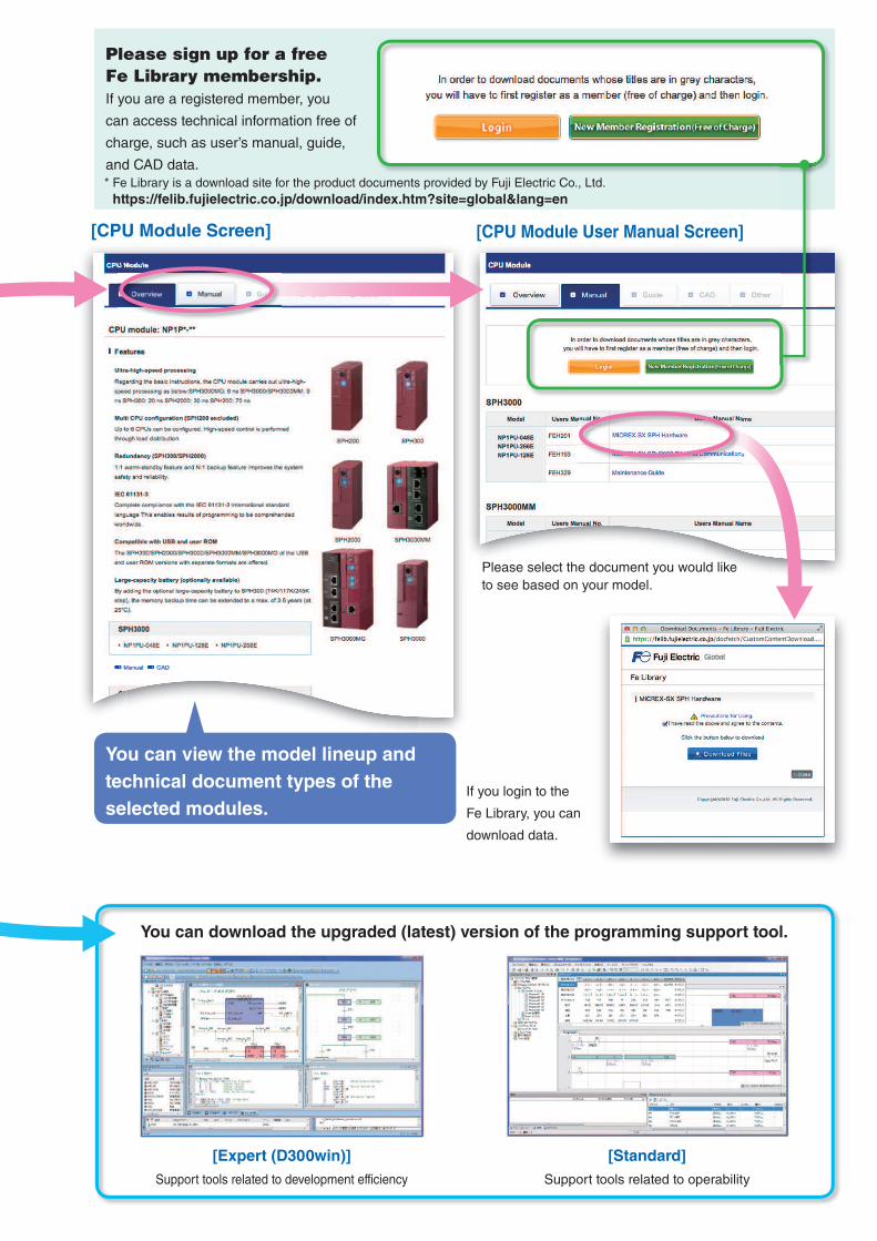
Please sign up for a free
Fe Library membership.
If you are a registered member, you
can access technical information free of
charge, such as user’s manual, guide,
and CAD data.
If you login to the
Fe Library, you can
download data.
Please select the document you would like
to see based on your model.
[CPU Module User Manual Screen][CPU Module Screen]
[Expert (D300win)]
Support tools related to development efficiency
[Standard]
Support tools related to operability
You can download the upgraded (latest) version of the programming support tool.
You can view the model lineup and
technical document types of the
selected modules.
* Fe Library is a download site for the product documents provided by Fuji Electric Co., Ltd.
https://felib.fujielectric.co.jp/download/index.htm?site=global&lang=en

Printed in Japan 2018-3(C18/D01)2 FOLS 22B2-E-0004e
Appearance and specifications are subject to change without prior notice for the purpose of product improvement.
Gate City Ohsaki, East Tower,11-2, Osaki 1-chome, Shinagawa-ku, Tokyo 141-0032, Japan
Phone : +81-3-5435-7057Fax : +81-3-5435-7420URL : http://www.fujielectric.com/
Materials covered in this document are subject to revision due to the modification of the product.
Safety Precautions Before using this product, read the "Instruction Manual" and "User manual" carefully or consult with the retailer
you purchased this product from and use this product correctly.
The product described in this catalog has not been designed and produced to be used for equipment or systems
which could endanger human life.
Contact your dealer if you are considering using the product described in this catalog for any applications which
have a large impact on life, the human body, community, important assets or rights (e.g., for power stations,
radiation-related facilities, railways, space/airline facilities, lifeline facilities, or medical equipment).
Please make sure that the use of the products does not lead to a serious accident in the event that a failure or
malfunction occurs in the products described in this catalog. And in cases of failure or malfunction, safety
measures should be prepared using external devices in a systematic manner as standard operating conditions
for the products.
For safe use, this product must be connected by those with specialized skills (in electric work, wiring work, etc.).
Use a power supply which is reinforced and isolated from an AC power supply for an external power supply to
connect to DC I/O (such as 24 V DC power supply). (You are recommended to use a power supply that conforms
to EN60950.) Otherwise, an accident or breakdown may result.
Before purchasing this product
For the details, price, and installation fee of the products included in this catalog, contact the retailer or Fuji
Electric Co., Ltd.
Please note that for product improvement, the appearance and specifications may be subject to change without
prior notice.
Please note in advance that printed and actual colors may differ slightly.


