potentials and state couplings andmultidimensional tunneling calculations for thephotodissociation of phenol†
Ke R. Yang, Xuefei Xu, Jingjing Zheng and Donald G. Truhlar*
We present an improved version of the anchor points reactive potential (APRP) method for potential energy
surfaces; the improvement for the surfaces themselves consists of using a set of internal coordinates with
better global behavior, and we also extend the method to fit the surface couplings. We use the newmethod
to produce a 3 � 3 matrix of diabatic potential energy surfaces and couplings for the photodissociation of
phenol as functions of 33 nonredundant internal coordinates. The diabatic potential matrix is based on two
kinds of calculations at a sequence of anchor points along the O–H dissociation coordinate: (1) fourfold way
diabatic calculations based on MC-QDPT/jul-cc-pVDZ calculations for the potential energy surfaces and
diabatic couplings as functions of the O–H bond stretch, C–O–H bond angle, and C–C–O–H torsion
and for the diabatic couplings as functions of the nine out-of-plane phenoxyl distortion coordinates and
(2) M06-2X/jul-cc-pVDZ density functional Hessian calculations for the potentials along the 30
vibrational coordinates of the phenoxyl group. The potential energy surfaces and couplings are used to
calculate and characterize adiabatic surfaces and conical intersections, and the resulting equilibrium
geometries, vibrational frequencies, and vertical excitation energies are in good agreement with available
reference data. We also calculate the geometries of the minimum energy conical intersections. The
surfaces and couplings are used for full-dimensional tunneling calculations of the adiabatic
photodissociation rate, i.e., the rate of O–H bond fission following photoexcitation. Finally we use the
couplings to provide indicators of which vibrational modes are effective in promoting dissociation.
1. Introduction
By separating the electronic and nuclear degrees of freedom,the widely used Born–Oppenheimer (BO) approximation1 leadsthe useful concepts of adiabatic states and potential energysurfaces (PESs). Adiabatic PESs are (3N � 6)-dimensionalhypersurfaces (where N is the number of atoms in a molecule)with (3N � 8)-dimensional cuspidal ridges along conical inter-section (CI) seams where two or more adiabatic PESs aredegenerate. The couplings between nuclear motions and elec-tronic motions are usually called nonadiabatic couplings, andthey are responsible for nonadiabatic transitions betweendifferent adiabatic states and for the development of coherentsuperpositions of adiabatic electronic states as the nuclearpositions evolve. Nonadiabatic couplings are usually small inregions removed from conical intersection seams and from theregions of near degeneracy surrounding them, and when they
ory Center, Supercomputing Institute,
Minnesota 55455-0431, USA. E-mail:
tion (ESI) available. See DOI:
hemistry 2014
are small, nuclear motions can be treated to a good approxi-mation as evolving on a single adiabatic PES.2
The BO approximation breaks down when two or moreadiabatic PESs approach closely or intersect. The nonadiabaticcouplings vary rapidly in such regions and become singular atCIs, thereby promoting nonadiabatic transitions in thoseregions. To model electronically nonadiabatic processes wheretwo or more electronic states are coupled via nonadiabaticcouplings, one can use either the adiabatic representation or adiabatic representation.3 In the adiabatic representation, whichis unique, the electronic Hamiltonian (always dened here, asusual, to also include nuclear repulsion) is diagonal; the diag-onal elements are the adiabatic PESs Vi, and the semiclassicallydominant nonadiabatic couplings are vectors deriving from theaction of nuclear momentum operators on the adiabatic elec-tronic wave functions. In a diabatic representation, these vectorcouplings are negligible (or assumed negligible), and diabaticelectronic states and their associated PESs, Uii, are coupledthrough scalar off-diagonal elements, Uij, of the electronicHamiltonian; these off-diagonal elements are called diabaticcouplings. Diabatic states are sometimes called quasidiabaticstates because strict diabatic states, in which the nuclear-momentum couplings are not just negligible but zero, do notexist in general.4 Thus diabatic states are not uniquely dened,
Fig. 1 The figure shows the structure of the transition state on adia-batic surface S1, and it also shows four sets of geometrical parametersfor key eight C–C, C–O, and O–H bond lengths (in A) and the C–O–Hbond angle (in degrees). From top to bottom are values for the equi-librium geometry of the S1 state of phenol, the saddle point of the S1state (the structure shown), the ~X 2B1 state of phenoxyl radical, and theA 2B2 state phenoxyl radical. “N.A.” denotes not applicable.
Chemical Science Edge Article
Publ
ishe
d on
06
Aug
ust 2
014.
Dow
nloa
ded
by U
nive
rsity
of
Min
neso
ta -
Tw
in C
ities
on
07/1
2/20
14 1
7:50
:28.
View Article Online
and many schemes have been proposed to construct diabaticstates.5–31
Potential energy surfaces can be constructed in either theadiabatic or diabatic representation, but the cuspidal ridges ofthe adiabatic potentials and the singularity of nonadiabaticcouplings in ubiquitous conical intersection regions32 preventthe analytic representation of adiabatic PESs and nonadiabaticcouplings. On the other hand, diabatic potentials and couplingschange smoothly with respective to geometrical variations, andthey allow for convenient representation. Aer one has thediabatic PESs available, one can carry out dynamics calculationsin either the diabatic or the adiabatic representation, where thelatter would be obtained from the diabatic PESs and diabaticcouplings by transformations. In the present article, we developan analytic representation of the multidimensional coupledpotential energy surfaces for phenol in the diabatic represen-tation, in particular we use potentials obtained by fourfold-waydiabatization,17,31,33 and the resulting diabatic surfaces andcouplings yield the adiabatic surfaces and couplings by stan-dard equations given elsewhere.34
As a prototypical process in photochemistry, the photodis-sociation of phenol to phenoxyl radical and H atom has beenstudied extensively both experimentally and theoretically,especially in recent years.33,35–57 The photodissociation of phenolinvolves passage through a crossing region of the 1pp* excitedstate and the 1ps* state, which is repulsive along the O–Hdissociation coordinate r, and this crossing region surrounds aconical intersection (CI1) of the 1pp* and 1ps* states. Therepulsive 1ps* state further crosses the 1pp ground state atanother conical intersection (CI2) at larger r. Thus we need toconsider three adiabatic PESs called Vi, with i ¼ 1, 2, 3, or threediabatic PESs; the latter are the diagonal elements Uii of a 3 � 3matrix potential, but we call them Ui for simplicity. The roles ofthe two CIs in the photodissociation of phenol and of thevibrational modes that affect the probabilities of transitions atthe CIs have been studied extensively, leading to stimulatinginsights and debates. Wave-packet studies37,43,50,51 have beencarried out to study the dynamics of phenol photodissociation,but they were performed with two-dimensional potential energysurfaces by considering only the O–H stretching coordinate anda selected coupling mode. Due to the complexity of the phenolmolecule, which has 13 atoms and whose PESs are therefore 33-dimensional, only recently was there an attempt to get higher-dimensional PESs.54 Very recently, Zhu and Yarkony con-structed full-dimensional coupled PESs of phenol using a dia-batic Hamiltonian whose domain of denition was constructedusing quasiclassical surface hopping trajectories.55 In thepresent article we present full-dimensional coupled PESs ofphenol as obtained by a quite different approach. Either set ofcoupled PESs should be able to lead to more complete studies ofthe phenol photodissociation process including the key role ofthe phenoxyl ring vibrations.
The size of phenol prevents the use of many PES ttingapproaches, such as permutation-invariant polynomials,58–60
and the interpolated moving-least squares61–63 method, thathave been widely used for smaller systems. Here we use animproved version of our recently proposed anchor points
4662 | Chem. Sci., 2014, 5, 4661–4680
reactive potential (APRP) method,64 which combines generalanalytic forms for large-amplitude modes with molecule-specic and anchor-point-specic molecular mechanics termsfor small-amplitude modes, to obtain full-dimensional semi-global diabatic PESs for photodissociation of phenol. Theimprovement consists in the use of internal coordinates withbetter global behavior. The surfaces are based on partitioningthe internal coordinates into three groups: the reaction coor-dinate r (also called the primary coordinate), secondary coor-dinates s, and tertiary coordinates Q, and the potentials aresemiglobal in that they are dened for all possible values of theprimary and secondary coordinates but only for small-ampli-tude vibrations of the tertiary coordinates away from the planarreference geometry of the phenoxyl fragment.
The geometry and atomic numbering of phenol and phe-noxyl radical are shown in Fig. 1. (The structures mentioned inthe caption of Fig. 1 will be explained more fully below.) In thepresent work, the O–H ssion coordinate was chosen as thereaction coordinate r; the C1–O–H bond angle q and C2–C1–O–Htorsion angle f were chosen as secondary coordinates; and theinternal coordinates of phenoxyl were chosen as tertiary coor-dinates Q. We use smooth diabatic potentials and couplingsalong r and f calculated previously33 combined with newcalculations of the diabatic potentials and couplings along q
and small-amplitude-vibration approximations of the depen-dence of the potentials on the tertiary coordinates at severalanchor points (explained below).
Upon dissociation, the ground 1pp state of phenol diabati-cally connects to the excited A 2B2 state of phenoxyl radical andH atom, while the repulsive 1ps* state diabatically connects tothe ground ~X 2B1 state of phenoxyl radical and H atom. Thesediabatic connections are apparent in Fig. 2, which more prop-erly belongs in the results section but is placed here to providethe reader with a picture of the general shapes of the potentialsurfaces to make the presentation in Section 2 clearer.
Fig. 2 Calculated and APRP diabatic potential energy curves of phenolalong the O–H dissociation coordinate. The other geometric param-eters are fixed at their values at the equilibrium geometry of groundstate phenol. The locations of the conical intersections on the APRPsurfaces for these cuts are r ¼ 1.316 A and r ¼ 2.231 A, respectively.
Edge Article Chemical Science
Publ
ishe
d on
06
Aug
ust 2
014.
Dow
nloa
ded
by U
nive
rsity
of
Min
neso
ta -
Tw
in C
ities
on
07/1
2/20
14 1
7:50
:28.
View Article Online
This paper has two “take home” messages – (i) improvedmethodology that others may want to adopt and (ii) newinsights into the excited state photochemistry of a prototypemolecule. Because the paper is multi-faceted, we close theintroduction with a guide to the contents of the varioussections.
Section 2 presents the improved version of the APRPmethod.The APRP method stands in relation to full surface tting ascombined quantum mechanical and molecular mechanical(QM/MM) methods stand in relation to pure quantummechanics.65 In QM/MM methods, most of a system is treatedby MM, but a subset of atoms is treated by QM. In APRP, thedependence of the potential onmost coordinates (called tertiarycoordinates) is treated by MM, but the dependence on a subsetof the coordinates (called primary and secondary coordinates) istreated by completely general surface tting. Furthermore, thetreatment of the MM subsystem in the APRP goes beyondconventional MM in several respects: rst, although thedependence of the potential on tertiary coordinates uses a typeof MM functional form, the coordinates are chosen to havebetter global behavior than those usually used in MM; second,the parameters in the MM part are not general parameterschosen to be reasonable for typical systems, but rather than aresystem specic; third, as compared to previous system-specicMM methods,66,67 the MM parameters vary as functions of theprimary coordinates. A key element of the treatment is that,unlike conventional MM, the APRP method is applicable toreactive systems.
Section 2 contains many equations; although these are theheart of the paper, readers only interested in take homemessage (ii) need not fully absorb these equations in order toread the later sections. Section 3 presents the results of applyingthe APRP method not just to the ground-state potential energysurface of phenol but to a 3 � 3 matrix representation thatyields the three lowest singlet states and their couplings. We usethe results of this t to understand the stationary points on theadiabatic surfaces, the multidimensional character of elec-tronically adiabatic tunneling, the relation between the
thickness of a barrier and its closeness to a conical intersection,the conical intersection seams both for geometries where thediabatic coupling vanishes by symmetry and for generalgeometries where there is no symmetry (C1 point group), andthe possible role of various normal-mode vibrations in thephotodissociation process.
Here we summarize the APRP method, specializing thedescription to the case of phenol photodissociation. Thepotential of diabatic state i is written as
Ui ¼ U[1]i (r) + U[2]
i (s|r) + U[3]i (Q|r), (1a)
where f(x|r) denotes a function with a dependence on x and aparametric dependence on r, and the three terms on the rightside are called the primary, secondary, and tertiary terms.General functional forms were used to t U[1]
i and U[2]i with
tertiary coordinates xed at the reference geometry, and we takeU[2]i to be separable:
U[2]i ¼ U[2,f]
i (f|r) + U[2,q]i (q|r). (1b)
The tertiary potentials are described by interpolationbetween preselected anchor points with tent functions:
U½3�i ¼
XNA
a¼1
U½a�i
�Q½a��T
½a�i ðrÞ; (2)
where U[a]i (Q[a]) is the expansion of the potential energy of dia-
batic state i around anchor point a, and T[a]i (r) is the tentfunction at anchor point a.
In the present case of phenol, all diabatic calculations werecarried out by fourfold-way diabatization using multi-congura-tional quasi-degenerate perturbation theory (MC-QDPT)68 withthe jul-cc-pVDZ basis set,69 as described previously.33 Morespecically, we calculated the diabatic states U1 (
1pp), U2 (1pp*),
and U3 (1ps*) along the chosen reaction coordinate r (O–Hdistance) and secondary coordinates q (C1–O–H bond angle) andf (C2–C1–O–H torsion) with other coordinates xed, and we usedthese calculations to t the primary and secondary potentials.The scans of r and f were performed in the same way as in theprevious work;33 in particular, rigid scans of the C1–O–H bend (q,with values of 90, 100, 107, 120, and 130�) were carried out atvarious r from 0.964 to 5.0 A with other coordinates taken as thesame as those obtained for the planar equilibrium geometry ofground-state phenol by the complete-active-space self-consistent-eld (CASSCF)70 method with the aug-cc-pVTZ basis set.71
Primary potentials. The primary potential of the diabatic1pp state was t to the Varshni model potential,72 given by.
U[1]1 ¼ D1{1 � (r1/r)exp[�b1((r1/r)
2 � 1)]}2. (4)
The diabatic 1pp* state has aminimum near the ground-stateequilibrium distance re, and it crosses the diabatic rst 1ps*
state at about 1.3 A and a second 1ps* state of higher energy atabout 1.5 A. For the photodissociation of phenol, the 1pp* stateis only important in the small-r range, so it is acceptable to t theU[1]2 (r) curve to a Morse potential73 and we used
U[1]2 ¼ D2{1 � exp[�a(r � r2)]}
2 + A2. (5)
A three-term function was used to t the repulsive potentialof rst diabatic 1ps* state:
U½1�3 ¼
X3i¼1
ai exp½�a3;iðr� r3;iÞ� þ A3: (6)
Secondary potentials. The torsion potential U[2]i (f|r) of dia-
batic state i is tted with the following expression:
U½2;f�i ¼
Xnjj¼1
Wi;jðrÞð1� cos 2fÞj ; (7)
where nj is the number of terms to expand the torsion potential[nj ¼ 1 for diabatic states U1 and U2 (
1pp and 1pp*) and nj ¼ 2for diabatic state U3 (
1ps*)], and Wi,j is the barrier height of thejth term. The latter was expanded as a linear combination ofGaussian functions, given by
Wi;j ¼Xnkk¼1
Ai;j;k exph�ai;j;k
�r� ri;j;k
�2i: (8)
In tting the C1–O–H bending potentials, we used cos qrather than q in order to have the proper symmetry of bendpotentials with respect to p � Dq and p + Dq:
U½2;q�i ¼
Xnjj¼2
ki;jðrÞðcos q� cos qi;0ðrÞÞj (9)
4664 | Chem. Sci., 2014, 5, 4661–4680
The force constant ki,j was further expanded with linearcombinations of Gaussians similar to eqn (8). A hyperbolictangent function is used to t the dependence of cos qi,0 on r:
cos qi;0 ¼ cos qi;1 þ 1þ tanhðai;1ðr� ri;1ÞÞ2
ðcos qi;2 � cos qi;1Þ(10)
where cos qi,1 and cos qi,2 are constant parameters.Tertiary potentials. Now we turn to U[3]
i , which depends ontertiary coordinates and depends parametrically on r throughthe use of anchor points. The dependence of the diabaticpotentials on tertiary coordinates is needed only for smallextensions from planar geometries. For planar geometries, thediabatic states U1 (
1pp), U2 (1pp*), and U3 (
1ps*) belong to theA0, A0, and A00irreducible representations, respectively, and asshown in Fig. 2, the two states with same symmetries are alwayswell separated, while the intersecting diabatic states along thereaction coordinate r have different symmetries; thus theadiabatic states are good approximations to the diabatic statesunder the Cs symmetry constraint of the planar geometries.Hence we chose anchor points with planar structures andobtained the diabatic states at each anchor point by adiabaticcalculations of the correct symmetry as described next.
For diabatic states U1 (1pp) and U3 (
1ps*), since they are thelowest states of their symmetry, we utilize ground-state Kohn–Sham calculations with the M06-2X exchange-correlationpotential74 and the jul-cc-pVDZ basis set to perform partialoptimization (optimizing all secondary and tertiary coordinatesfor xed r) and calculate the Hessians at each of the anchorpoints. For diabatic state U2 (
1pp*), since it is an excited state(S1) in A0 symmetry, time-dependent density functional theory(TDDFT)75,76 was used to perform the partial optimization andHessian calculations, again with the M06-2X exchange-correla-tion potential and the jul-cc-pVDZ basis set.
For each diabatic state, four planar anchor points werechosen along the O–H dissociation coordinate; for U1, they areat r¼ 0.964, 1.32, 2.00, and 5.00 A, and for U2 and U3, they are atr ¼ 0.964, 1.32, 2.26, and 5.00 A. The rst anchor point for eachof the diabatic states has the ground-state equilibrium O–Hbond length calculated by CASSCF/jul-cc-pVDZ; the secondanchor point was chosen to have an O–H bond length close tothe rst conical intersection (CI1) in planar geometry; the thirdanchor points were chosen to have an O–H bond length close tothe second conical intersection (CI2); and the nal anchorpoints were chosen to yield the correct asymptotic limit ofphenoxyl radical.
The ground state of phenoxyl is ~X 2B1 and it has a low-lying A2B2 excited state; these states connect diabatically to surfaces U3
(1ps*) and U1 (1pp), respectively, and they were optimized with
UM06-2X/jul-cc-pVDZ. The geometric parameters and Hessiansof phenoxyl in these two states were used for the nal anchorpoints with r ¼ 5.00 A. For anchor points with other O–H bondlengths, geometrical parameters and Hessians were obtainedwith partial optimizations. Since U2 state is not very relevantaer the rst conical intersection (CI1), the geometricalparameters and Hessian elements at r ¼ 1.32 A were used for itat the next two anchor points r ¼ 2.26 A and 5.00 A.
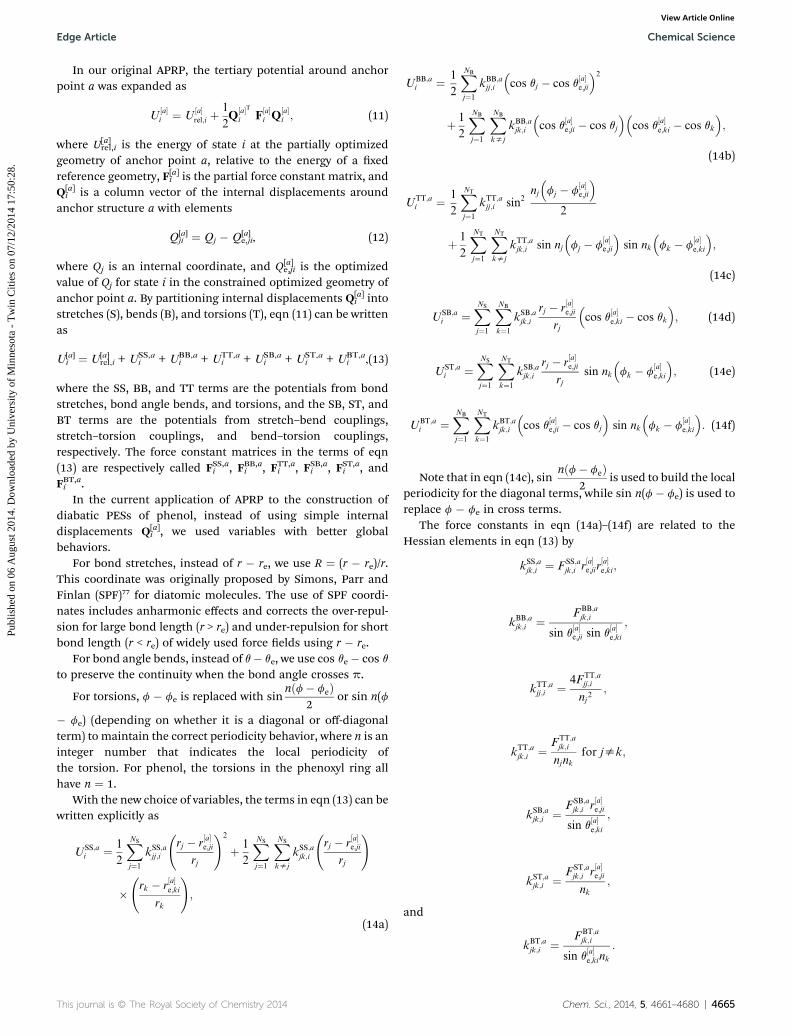
In our original APRP, the tertiary potential around anchorpoint a was expanded as
U½a�i ¼ U
½a�rel;i þ
1
2Q
½a�Ti F
½a�i Q
½a�i ; (11)
where U[a]rel,i is the energy of state i at the partially optimized
geometry of anchor point a, relative to the energy of a xedreference geometry, F[a]i is the partial force constant matrix, andQ[a]i is a column vector of the internal displacements around
anchor structure a with elements
Q[a]ji ¼ Qj � Q[a]
e,ji, (12)
where Qj is an internal coordinate, and Q[a]e,ji is the optimized
value of Qj for state i in the constrained optimized geometry ofanchor point a. By partitioning internal displacements Q[a]
i intostretches (S), bends (B), and torsions (T), eqn (11) can be writtenas
U[a]i ¼ U[a]
rel,i + USS,ai + UBB,a
i + UTT,ai + USB,a
i + UST,ai + UBT,a
i ,(13)
where the SS, BB, and TT terms are the potentials from bondstretches, bond angle bends, and torsions, and the SB, ST, andBT terms are the potentials from stretch–bend couplings,stretch–torsion couplings, and bend–torsion couplings,respectively. The force constant matrices in the terms of eqn(13) are respectively called FSS,ai , FBB,ai , FTT,ai , FSB,ai , FST,ai , andFBT,ai .
In the current application of APRP to the construction ofdiabatic PESs of phenol, instead of using simple internaldisplacements Q[a]
i , we used variables with better globalbehaviors.
For bond stretches, instead of r � re, we use R ¼ (r � re)/r.This coordinate was originally proposed by Simons, Parr andFinlan (SPF)77 for diatomic molecules. The use of SPF coordi-nates includes anharmonic effects and corrects the over-repul-sion for large bond length (r > re) and under-repulsion for shortbond length (r < re) of widely used force elds using r � re.
For bond angle bends, instead of q� qe, we use cos qe� cos qto preserve the continuity when the bond angle crosses p.
For torsions, f � fe is replaced with sinnðf� feÞ
2or sin n(f
� fe) (depending on whether it is a diagonal or off-diagonalterm) to maintain the correct periodicity behavior, where n is aninteger number that indicates the local periodicity ofthe torsion. For phenol, the torsions in the phenoxyl ring allhave n ¼ 1.
With the new choice of variables, the terms in eqn (13) can bewritten explicitly as
With our new choice of variables to describe bond stretches,bond angle bends, and torsions, eqn (14) have much betterbehavior than the terms used previously for large distortions,although they require no more information. Thus, we recom-mend using them to construct force elds in the future. Inaddition to the above terms, we added a repulsive Born–Mayerpotential between all pairs (1–4, 2–5, and 3–6) of para carbonatoms to all three diabatic potentials (see Fig. 1 for atomicnumbering); this prevents the nonbonded atoms from gettingtoo close during trajectories. The Born–Mayer potential isgiven as
VBM ¼ BX
X�Y¼1�4;2�5;3�6
expð�arX�YÞ (15)
where the interaction parameters are taken from the litera-ture:78 B is 42000 kcal mol�1, and a is 3.58 A�1.
In a similar spirit to that used in the APRP representations ofthe diabatic potentials, the diabatic couplings are expressed as
Uij ¼ U[3,S]ij (S|r) + U[2,f]
ij (f|r), (16)
where U[2,f]ij is tted to MC-QDPT data, and U[3,S]
ij is constructedby interpolating linear expansions around anchor structureswith tent functions:
U½3;S�ij ¼
XNA
a¼1
U
½0�ij;a þ
X9a¼1
AijaaSa
!TaðrÞ; (17)
where U[0]ij,a is a constant parameter for anchor structure a, and
Ta(r) is the tent function with the same form as T[a]i (r) used fortertiary potential. The parameter Aijaa in the representation ofdiabatic coupling Uij equals the rst partial derivative of Uij withrespect to Sa at anchor structure a. Four planar anchor pointswith other geometric parameters xed at CASSCF/aug-cc-pVTZoptimized ground state minimum were chosen along the O–Hdissociation coordinate, and they are the same for all diabaticcouplings: r ¼ 0.964, 1.32, 2.26, and 5.00 A.
The diabatic coupling U12 of diabatic state U1 (1pp) to dia-batic state U2 (
1pp*) is less important than the other couplingssince the energy separation between those two states is quitelarge at all considered geometries. Therefore we used a simplertreatment for this coupling. In particular, we set all A12aaparameters equal to zero, and we set U[0]
12,3 and U[0]12,4 equal to
zero; we set U[0]12,1 ¼ �0.02 eV, and we set U[0]
12,2 ¼ �0.03 eV.By symmetry, there is no contribution to diabatic couplings
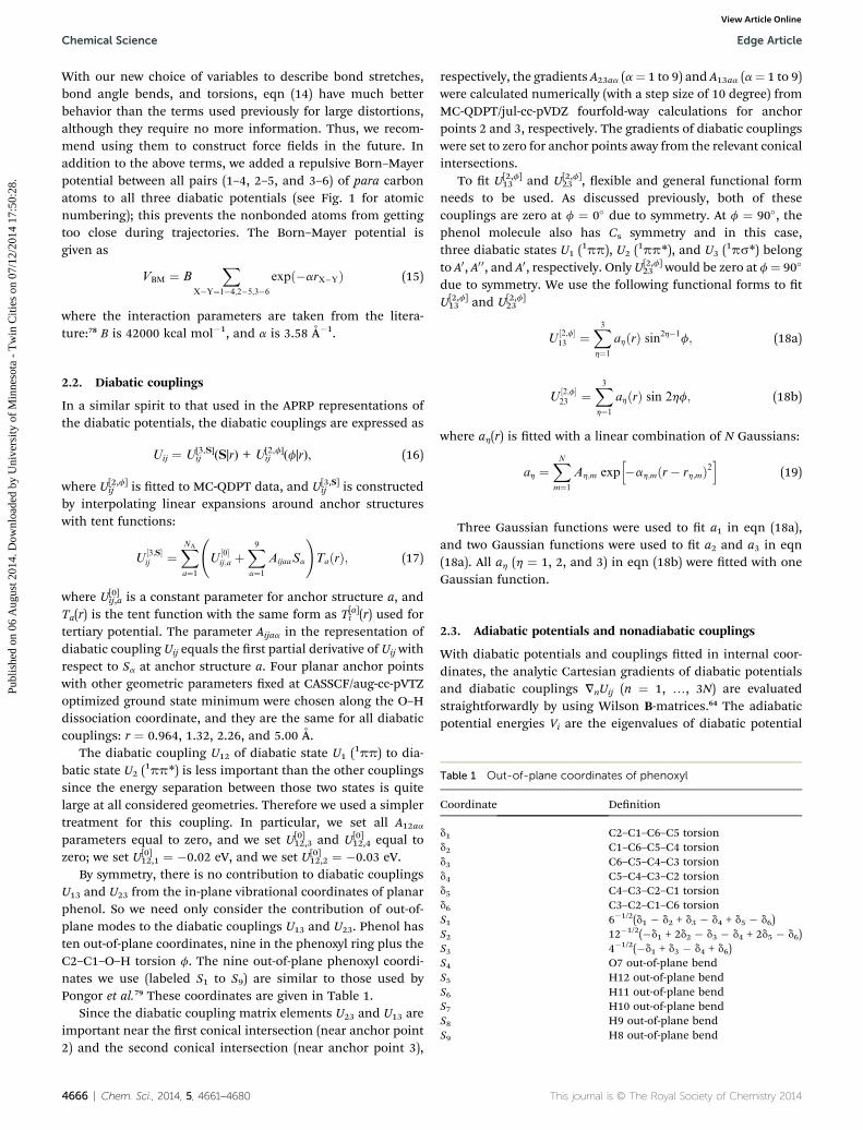
U13 and U23 from the in-plane vibrational coordinates of planarphenol. So we need only consider the contribution of out-of-plane modes to the diabatic couplings U13 and U23. Phenol hasten out-of-plane coordinates, nine in the phenoxyl ring plus theC2–C1–O–H torsion f. The nine out-of-plane phenoxyl coordi-nates we use (labeled S1 to S9) are similar to those used byPongor et al.79 These coordinates are given in Table 1.
Since the diabatic coupling matrix elements U23 and U13 areimportant near the rst conical intersection (near anchor point2) and the second conical intersection (near anchor point 3),
4666 | Chem. Sci., 2014, 5, 4661–4680
respectively, the gradients A23aa (a¼ 1 to 9) and A13aa (a¼ 1 to 9)were calculated numerically (with a step size of 10 degree) fromMC-QDPT/jul-cc-pVDZ fourfold-way calculations for anchorpoints 2 and 3, respectively. The gradients of diabatic couplingswere set to zero for anchor points away from the relevant conicalintersections.
To t U[2,f]13 and U[2,f]
23 , exible and general functional formneeds to be used. As discussed previously, both of thesecouplings are zero at f ¼ 0� due to symmetry. At f ¼ 90�, thephenol molecule also has Cs symmetry and in this case,three diabatic states U1 (
1pp), U2 (1pp*), and U3 (
1ps*) belongto A0, A0 0, and A0, respectively. Only U[2,f]
23 would be zero at f¼ 90�
due to symmetry. We use the following functional forms to tU[2,f]13 and U[2,f]
23
U½2;f�13 ¼
X3h¼1
ahðrÞ sin2h�1f; (18a)
U½2;f�23 ¼
X3h¼1
ahðrÞ sin 2hf; (18b)
where ah(r) is tted with a linear combination of N Gaussians:
ah ¼XNm¼1
Ah;m exph�ah;mðr� rh;mÞ2
i(19)
Three Gaussian functions were used to t a1 in eqn (18a),and two Gaussian functions were used to t a2 and a3 in eqn(18a). All ah (h ¼ 1, 2, and 3) in eqn (18b) were tted with oneGaussian function.
2.3. Adiabatic potentials and nonadiabatic couplings
With diabatic potentials and couplings tted in internal coor-dinates, the analytic Cartesian gradients of diabatic potentialsand diabatic couplings VnUij (n ¼ 1, ., 3N) are evaluatedstraightforwardly by using Wilson B-matrices.64 The adiabaticpotential energies Vi are the eigenvalues of diabatic potential
a See Fig. 1 for numbering of atoms. b jul-cc-pVDZ. c Ref. 87. d Ref. 88.
Edge Article Chemical Science
Publ
ishe
d on
06
Aug
ust 2
014.
Dow
nloa
ded
by U
nive
rsity
of
Min
neso
ta -
Tw
in C
ities
on
07/1
2/20
14 1
7:50
:28.
View Article Online
energy matrix U. The analytic Cartesian gradients of the adia-batic potentials and the nonadiabatic couplings are34
VnVi ¼Xj;k
c*ijcjkVnUjk; (20)
and
Fij ¼
8><>:
1
Vj � Vi
Xk;l
c*ikcjlVnUkl ðisjÞ
0 ði ¼ jÞ; (21)
where n¼ 1,., 3N and cij is the element of orthogonal matrix Cthat diagonalizes the diabatic potential matrix U.
2.4. Further information about the surfaces and couplings
Full details of the development of the APRP method and theoptimized parameters are given in the supplementary mate-rial.80 A Fortran subroutine that provides the diabatic potentialenergy surface matrices and their analytic derivatives, adiabaticpotential energies and their analytic derivatives, and nonadia-batic couplings is available in the POTLIB library.81,82
2.5. Additional computational details
The reference orbitals and diabatic prototypes employed in theMC-QDPT fourfold-way diabatizations are specied in ref. 33.These calculations were performed with HONDOPLUS.83
For tting the tertiary potential, the adiabatic partial opti-mizations and Hessian calculations at anchor points were per-formed by Kohn–Sham density functional theory with the M06-2X exchange-correlation functional and the jul-cc-pVDZ basisset with ultrane grids by using Gaussian 09.84
The geometry optimizations and frequency analyses ofequilibrium and transition structures were performed by thePOLYRATE program85 with the APRP surfaces. The geometry ofthe minimum energy conical intersection (MECI) betweenadiabatic states Vi and Vj was obtained by minimizing the
penalty function F ¼ 12ðVi þ VjÞ þ aðVi � VjÞ2 with a ¼ 105 Eh
�1
(where Eh ¼ 1 hartree).We ran thousands of sample dissociative coupled-surface
trajectories to conrm that the nal versions of the coupledpotential energy surfaces conserve energy and angularmomentum and do not visit regions of conguration spacewhere the surfaces yield unphysical results. These calculationswere carried out with the ANT program.86
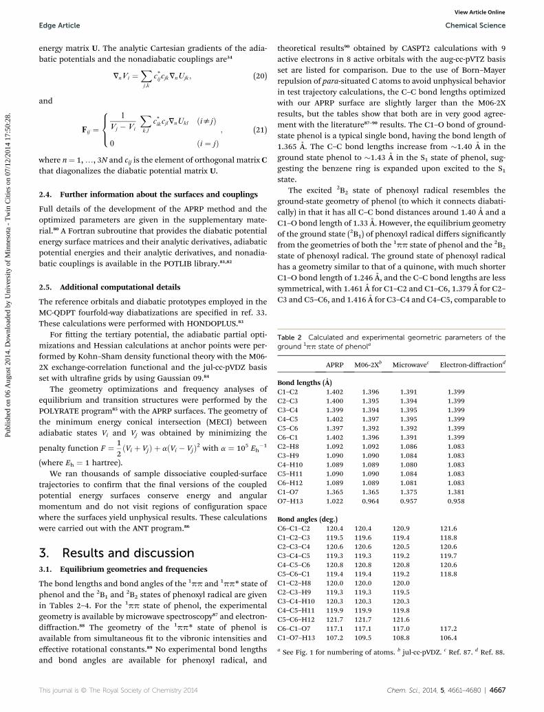
3. Results and discussion3.1. Equilibrium geometries and frequencies
The bond lengths and bond angles of the 1pp and 1pp* state ofphenol and the 2B1 and
2B2 states of phenoxyl radical are givenin Tables 2–4. For the 1pp state of phenol, the experimentalgeometry is available by microwave spectroscopy87 and electron-diffraction.88 The geometry of the 1pp* state of phenol isavailable from simultaneous t to the vibronic intensities andeffective rotational constants.89 No experimental bond lengthsand bond angles are available for phenoxyl radical, and
theoretical results90 obtained by CASPT2 calculations with 9active electrons in 8 active orbitals with the aug-cc-pVTZ basisset are listed for comparison. Due to the use of Born–Mayerrepulsion of para-situated C atoms to avoid unphysical behaviorin test trajectory calculations, the C–C bond lengths optimizedwith our APRP surface are slightly larger than the M06-2Xresults, but the tables show that both are in very good agree-ment with the literature87–90 results. The C1–O bond of ground-state phenol is a typical single bond, having the bond length of1.365 A. The C–C bond lengths increase from �1.40 A in theground state phenol to �1.43 A in the S1 state of phenol, sug-gesting the benzene ring is expanded upon excited to the S1state.
The excited 2B2 state of phenoxyl radical resembles theground-state geometry of phenol (to which it connects diabati-cally) in that it has all C–C bond distances around 1.40 A and aC1–O bond length of 1.33 A. However, the equilibrium geometryof the ground state (2B1) of phenoxyl radical differs signicantlyfrom the geometries of both the 1pp state of phenol and the 2B2
state of phenoxyl radical. The ground state of phenoxyl radicalhas a geometry similar to that of a quinone, with much shorterC1–O bond length of 1.246 A, and the C–C bond lengths are lesssymmetrical, with 1.461 A for C1–C2 and C1–C6, 1.379 A for C2–C3 and C5–C6, and 1.416 A for C3–C4 and C4–C5, comparable to
a See Fig. 1 for numbering of atoms. b TD-DFT with the M06-2Xfunctional and the jul-cc-pVDZ basis set. c Ref. 89.
Chemical Science Edge Article
Publ
ishe
d on
06
Aug
ust 2
014.
Dow
nloa
ded
by U
nive
rsity
of
Min
neso
ta -
Tw
in C
ities
on
07/1
2/20
14 1
7:50
:28.
View Article Online
the C–O bond length (1.222 A) and two C–C bond lengths (1.334,and 1.477 A) in 1,4-benzoquinone.91 The vibrational frequenciesof the ground-state adiabatic surface were calculated at theminimum-energy geometries of the APRP surface, and they arecompared in Fig. 3 to M06-2X frequencies and available exper-imental fundamental frequencies of phenol92 and phenoxylradical.93 The frequencies calculated with our adiabatic PESreproduce the M06-2X results, both overestimating the experi-mental frequencies slightly. The overestimate by M06-2X isconsistent with known trends,94 but nevertheless we did notscale the density functional frequencies or Hessians in thepresent work.
3.2. Energetics and thermal adiabatic rate constants
The adiabatic vertical excitation energies of phenol and phe-noxyl radical calculated with the APRP PESs are shown andcompared with previous theoretical and available experimentalresults in Table 5. Experimentally, the spectrum for the opticallyallowed excitation of phenol from its ground state to the 1pp*
state has a maximum at 4.58 eV.95 The excitation to the 1ps*
state is electric dipole forbidden, and no reliable experimentalresult is available. Previous high-level ab initio studies sug-gested that the vertical excitation energy of the 1ps* state
4668 | Chem. Sci., 2014, 5, 4661–4680
should be in the range 5.6–5.9 eV.33,44,51 Our APRP surfacepredicts vertical excitation energies to be 4.58 and 5.88 eV forexcitations to the 1pp* state and the 1ps* state, respectively, ingood agreement with these reference values. In comparison tothese results, the MC-QDPT/jul-cc-pVDZ results that were usedin the construction of primary and secondary potential yieldvertical excitation energies of 4.70 and 5.86 eV for the two statesof phenol.33 The slight difference between the APRP and MC-QDPT values is a result of the different equilibrium geometry ofphenol used in the calculations. The CASSCF/aug-cc-pVTZoptimized geometry was used in the calculation with MC-QDPTwhile the equilibrium geometries of the APRP surface were usedfor the APRP result. The fact that the APRP agrees slightly betterwith the reference values is just a fortuitous result of thistechnical shi in geometric parameters.
The excitation energy of ground state phenoxyl radical to the2B2 state was rst determined to be 1.06 eV in a gas-phaseultraviolet photoelectron spectroscopy experiment.96 It was laterobserved to be 1.10 eV by UV-VIS and IR polarization spectros-copy of phenoxyl radical in cryogenic argon matrices.97 The
Fig. 3 Comparison of vibrational frequencies calculated from theground-state APRP surface, from M06-2X calculations with availableexperimental results. Top: the 1pp state of phenol; bottom: the ~X 2B1
state of phenoxyl radical.
Edge Article Chemical Science
Publ
ishe
d on
06
Aug
ust 2
014.
Dow
nloa
ded
by U
nive
rsity
of
Min
neso
ta -
Tw
in C
ities
on
07/1
2/20
14 1
7:50
:28.
View Article Online
excitation energy of phenoxyl radial from the 2B1 state to the 2B2
state calculated by our APRP surface is 1.07 eV, agreeing quitewell with experimental results.
The equilibrium dissociation energy of the O–H bondcalculated from the APRP PES is 3.93 eV, which is smaller thanthe experimentally derived De,33,98,99 as shown in Table 5.
Table 5 Vertical excitation energies of phenol and phenoxyl and the eq
a The equilibrium geometries of phenol and phenoxyl radical were optimienergies and the equilibrium dissociation energy for breaking the O–H bofrom ref. 95. g Derived in ref. 33 from ref. 98 (rst value) and ref. 99 (seco
The classical adiabatic excitation energy, i.e., the energy ofthe S1 state minimum minus that of the S0 state minimum onthe APRP surfaces was calculated to be 4.42 eV. We can calculatethe quantal adiabatic excitation energy, i.e., the 000 energy,which is the energy of the S1 zero point level minus that of the S0zero point level on the APRP surfaces, by adding the S1 zeropoint energy (2.66 eV) and subtracting the S0 zero point energy(2.85 eV); that yields 4.22 eV. This may be compared to theexperimental value51 of 4.51 eV.
Although there has been considerable emphasis on thelocation of the conical intersection, we should keep in mindthat there is generally a saddle point on the lower adiabaticsurface on the side of a conical intersection,100 and for somepurposes the characteristics of this saddle point are equallyimportant or more important than the characteristics of theconical intersection. The transition state (i.e., saddle point) forH dissociation on the rst excited adiabatic state surface waslocated, with a classical barrier height of 0.72 eV with respect tothe S1 minimum (or 5.14 eV with respect to the S0 minimum). Atthe saddle point geometry, the energies of the S0 and S2 states ofphenol are 1.66 and 5.95 eV, respectively. The large energy gap(0.81 eV) between the S1 and S2 states at the saddle pointsuggests that an adiabatic model of dissociation on the S1surface might be a good zero-order model for the earlydynamics of H-dissociation. The transition state has twononplanar structures, which are mirror images of each other,with C2–C1–O–H torsion angles of�20.4 and 20.4�. As shown inFig. 1, the C–C and C–O bond lengths in the transition statestructures are very close to those in the ground state phenoxylradical. The O–H bond length of the transition state structuresis 1.33 A, close to 1.32 A at which value the S1 and S2 states ofphenol intersect for planar geometry at the MC-QDPT level.33
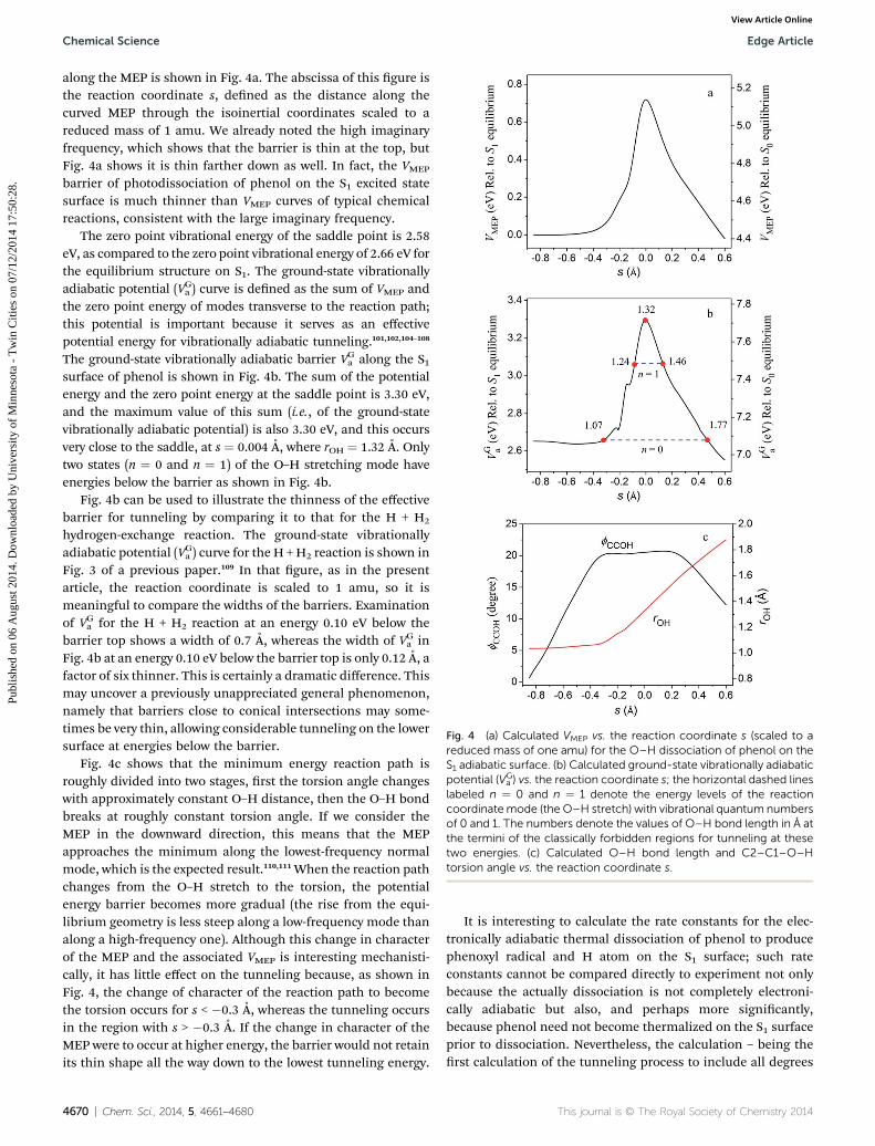
The imaginary frequency at the saddle point is 4271i cm�1,which is rather high because the reduced mass for hydrogenicdissociation is low and because the saddle point is so close to aconical intersection. (A barrier due to a CI may be thin becausethe CI is pointy at the top, as compared to at for a saddlepoint.) The minimum energy path in mass-scaled (i.e., iso-inertial) coordinates101,102 (MEP) was calculated using the Page–McIver algorithm,103 and the calculated potential energy VMEP
zed with the APRP PES and were used to calculate the vertical excitationnd. b Ref. 33. c Ref. 49. d Ref. 44. e Ref. 51. f Highest peak value obtainednd value). h Ref. 96. i Ref. 97.
Fig. 4 (a) Calculated VMEP vs. the reaction coordinate s (scaled to areduced mass of one amu) for the O–H dissociation of phenol on theS1 adiabatic surface. (b) Calculated ground-state vibrationally adiabaticpotential (VG
a ) vs. the reaction coordinate s; the horizontal dashed lineslabeled n ¼ 0 and n ¼ 1 denote the energy levels of the reactioncoordinatemode (the O–H stretch) with vibrational quantum numbersof 0 and 1. The numbers denote the values of O–H bond length in A atthe termini of the classically forbidden regions for tunneling at thesetwo energies. (c) Calculated O–H bond length and C2–C1–O–Htorsion angle vs. the reaction coordinate s.
Chemical Science Edge Article
Publ
ishe
d on
06
Aug
ust 2
014.
Dow
nloa
ded
by U
nive
rsity
of
Min
neso
ta -
Tw
in C
ities
on
07/1
2/20
14 1
7:50
:28.
View Article Online
along the MEP is shown in Fig. 4a. The abscissa of this gure isthe reaction coordinate s, dened as the distance along thecurved MEP through the isoinertial coordinates scaled to areduced mass of 1 amu. We already noted the high imaginaryfrequency, which shows that the barrier is thin at the top, butFig. 4a shows it is thin farther down as well. In fact, the VMEP
barrier of photodissociation of phenol on the S1 excited statesurface is much thinner than VMEP curves of typical chemicalreactions, consistent with the large imaginary frequency.
The zero point vibrational energy of the saddle point is 2.58eV, as compared to the zero point vibrational energy of 2.66 eV forthe equilibrium structure on S1. The ground-state vibrationallyadiabatic potential (VGa ) curve is dened as the sum of VMEP andthe zero point energy of modes transverse to the reaction path;this potential is important because it serves as an effectivepotential energy for vibrationally adiabatic tunneling.101,102,104–108
The ground-state vibrationally adiabatic barrier VGa along the S1surface of phenol is shown in Fig. 4b. The sum of the potentialenergy and the zero point energy at the saddle point is 3.30 eV,and the maximum value of this sum (i.e., of the ground-statevibrationally adiabatic potential) is also 3.30 eV, and this occursvery close to the saddle, at s ¼ 0.004 A, where rOH ¼ 1.32 A. Onlytwo states (n ¼ 0 and n ¼ 1) of the O–H stretching mode haveenergies below the barrier as shown in Fig. 4b.
Fig. 4b can be used to illustrate the thinness of the effectivebarrier for tunneling by comparing it to that for the H + H2
hydrogen-exchange reaction. The ground-state vibrationallyadiabatic potential (VGa ) curve for the H +H2 reaction is shown inFig. 3 of a previous paper.109 In that gure, as in the presentarticle, the reaction coordinate is scaled to 1 amu, so it ismeaningful to compare the widths of the barriers. Examinationof VGa for the H + H2 reaction at an energy 0.10 eV below thebarrier top shows a width of 0.7 A, whereas the width of VGa inFig. 4b at an energy 0.10 eV below the barrier top is only 0.12 A, afactor of six thinner. This is certainly a dramatic difference. Thismay uncover a previously unappreciated general phenomenon,namely that barriers close to conical intersections may some-times be very thin, allowing considerable tunneling on the lowersurface at energies below the barrier.
Fig. 4c shows that the minimum energy reaction path isroughly divided into two stages, rst the torsion angle changeswith approximately constant O–H distance, then the O–H bondbreaks at roughly constant torsion angle. If we consider theMEP in the downward direction, this means that the MEPapproaches the minimum along the lowest-frequency normalmode, which is the expected result.110,111When the reaction pathchanges from the O–H stretch to the torsion, the potentialenergy barrier becomes more gradual (the rise from the equi-librium geometry is less steep along a low-frequency mode thanalong a high-frequency one). Although this change in characterof the MEP and the associated VMEP is interesting mechanisti-cally, it has little effect on the tunneling because, as shown inFig. 4, the change of character of the reaction path to becomethe torsion occurs for s < �0.3 A, whereas the tunneling occursin the region with s > �0.3 A. If the change in character of theMEP were to occur at higher energy, the barrier would not retainits thin shape all the way down to the lowest tunneling energy.
4670 | Chem. Sci., 2014, 5, 4661–4680
It is interesting to calculate the rate constants for the elec-tronically adiabatic thermal dissociation of phenol to producephenoxyl radical and H atom on the S1 surface; such rateconstants cannot be compared directly to experiment not onlybecause the actually dissociation is not completely electroni-cally adiabatic but also, and perhaps more signicantly,because phenol need not become thermalized on the S1 surfaceprior to dissociation. Nevertheless, the calculation – being therst calculation of the tunneling process to include all degrees
of freedom – provides valuable insight. The thermal rateconstants of the unimolecular H-dissociation of phenol on theV2 surface were calculated with canonical variational theory(CVT),112,113 with vibrations transverse to the reaction coordinatequantized. Tunneling was included in the calculations by fourdifferent methods: the zero-curvature tunneling (ZCT) approxi-mation,101,114 the small-curvature tunneling (SCT) approxima-tion,108 the large-curvature tunneling (LCT) approximation,115,116
and the microcanonically optimized tunneling (mOMT)approximation.116,117 The ZCT calculation may be considered tobe an approximation to the SCT one (as explained furtherbelow). The SCT calculations are vibrationally adiabatic and theLCT calculation is vibrationally nonadiabatic, and they alsohave different tunneling paths appropriate to the limits of smallcurvature of the reaction path and large curvature of the reac-tion path; the mOMT approximation chooses between them onthe basis that, for each tunneling energy, the tunnelingapproximation that yields the most tunneling (largest rateconstant) is expected to be most accurate.118,119 Since only twovibrational states of the O–H stretching mode have energy levelsbelow the barrier, we performed quantized-reactant-statetunneling calculations.120,121 We found that the SCT and mOMTapproximations give nearly the same result, both larger than theresult given by LCT approximation. Therefore the SCT result isour most accurate, but we show both the ZCT and SCT results inTable 6 because the comparison is physically interesting. TheZCT result shows the effect of tunneling along the MEP as if itwere a straight path in isoinertial coordinates, whereas the SCTresult includes corner cutting across the concave side of thecurved path to shorten the tunneling path and increase thetunneling probability. The unimolecular thermal rate constantsincrease by many orders of magnitude when one includestunneling, and the effect of corner cutting is very signicant.
The SCT tunneling probability in the n ¼ 0 state of the O–Hstretch (at an energy 2.66 eV above the equilibriumminimum ofthe S1 potential) is 7.5 � 10�6, and the SCT tunneling proba-bility in the n ¼ 1 state of the O–H stretch (at an energy of3.07 eV) is 0.050.
Without considering the tunneling effect, the lifetime of theS1 state, which is the reciprocal of the tabulated unimolecular
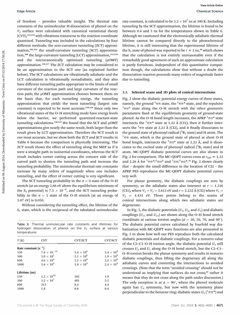
Table 6 Thermal unimolecular rate constants and lifetimes forhydrogen dissociation of phenol on the V2 surface at varioustemperatures
rate constant, is calculated to be 3.2� 107 ns at 300 K. Includingtunneling by the SCT approximation, the lifetime is found to bebetween 0.4 and 5 ns for the temperatures shown in Table 6.Although we cautioned that the electronically adiabatic thermallifetime cannot be compared directly to the photochemicallifetime, it is still interesting that the experimental lifetime ofthe S1 state of phenol was reported to be sz 2 ns,49 which showsthat the calculation is not entirely unreasonable even if theremarkably good agreement of such an approximate calculationis partly fortuitous. Independent of this quantitative compar-ison though, the calculations show that without a doubt thedissociation reaction proceeds many orders of magnitude fasterdue to tunneling.
3.3. Selected scans and 3D plots of conical intersections
Fig. 2 show the diabatic potential energy curves of three states,namely, the ground 1pp state, the 1pp* state, and the repulsive1ps* state along the O–H stretch with the other geometricparameters xed at the equilibrium geometry of ground-statephenol. As the O–H bond length increases, the APRP 1ps* stateintersects the 1pp* state at 1.32 A (CI1); then it further inter-sects the 1pp state at 2.23 A (CI2), and it nally dissociates tothe ground state of phenoxyl radical (2B1 state) and H atom. The1pp state, which is the ground state of phenol at short O–Hbond length, intersects the 1ps* state at 2.23 A, and it disso-ciates to the excited state of phenoxyl radical (2B2 state) and Hatom. MC-QDPT diabatic potential curves are also shown inFig. 2 for comparison. The MC-QDPT curves cross at rOH z 1.32and 2.26 A for 1pp*/1ps* and 1pp/1ps*.33 Fig. 2 shows clearlythat – despite the small difference in the location of CI2 – theAPRP PES reproduces the MC-QDPT diabatic potential curvesvery well.
For planar geometry, the diabatic couplings are zero bysymmetry, so the adiabatic states also intersect at r ¼ 1.316(CI1), where V2 ¼ V3 ¼ 5.613 eV and r¼ 2.232 A (CI2) where V1 ¼V2 ¼ 4.434 eV. Those points belong to the seams ofconical intersections along which two adiabatic states aredegenerate.
In Fig. 5, the diabatic potentials (U1, U2, and U3) and diabaticcouplings (U13 and U23) are shown along the O–H bond stretchcoordinate at various torsion angles (f ¼ 30, 50, 70, and 90�).The diabatic potential curves calculated by fourfold way dia-batization with MC-QDPT wave functions are also presented inFig. 5 to show how well our PES reproduce both the calculateddiabatic potentials and diabatic couplings. For a nonzero valueof the C2–C1–O–H torsion angle, the diabatic potential U3 stillcrosses U2 and U1 along the O–H bond stretch, but the C2–C1–O–H torsion breaks the planar symmetry and results in nonzerodiabatic couplings, thus liing the degeneracy all along theadiabatic curves and converting the intersections to avoidedcrossings. (Note that the term “avoided crossing” should not beunderstood as implying that surfaces do not cross;32 rather itmeans that they do not cross along the path under discussion.)The only exception is at f ¼ 90�, where the phenol moleculeagain has Cs symmetry, but now with the symmetry planeperpendicular to the benzene ring; diabatic states U2 (
Fig. 5 Calculated and APRP diabatic potentials (U1, U2, and U3) anddiabatic couplings (U13 and U23) of phenol along the O–H dissociationcoordinate r at various C2–C1–O–H torsion angles f. The othergeometric parameters are fixed at their values at the equilibriumgeometry of ground state phenol.
4672 | Chem. Sci., 2014, 5, 4661–4680
Chemical Science Edge Article
Publ
ishe
d on
06
Aug
ust 2
014.
Dow
nloa
ded
by U
nive
rsity
of
Min
neso
ta -
Tw
in C
ities
on
07/1
2/20
14 1
7:50
:28.
View Article Online
U3 (1ps*) now have A0 0 and A0 symmetry, respectively, and thediabatic coupling U23 is zero by symmetry. Our PES yields zerodiabatic coupling of U23 at f ¼ 90� by construction, shown inFig. 5d.
Three-dimensional plots of diabatic surfaces U2 and U3 andadiabatic surfaces V2 and V3 are shown in Fig. 6 as functions oftheO–H bond stretch and the C2–C1–O–H torsion coordinatewith the other geometric parameters xed with their values cor-responding to the equilibrium structure of ground-state phenol.The diabatic states cross at both planar and non-planar geome-tries, forming a seam with U2 ¼ U3 in the r and f space. Thediabatic coupling U23 is not zero for most nonplanar geometries,but it is zero along the f ¼ 0 cut that intersects the diabaticintersection seam at r ¼ 1.316 A to yield a conical intersectionthere, this is simply another view of the CI1 intersection shown inFig. 2. We should keep in mind that at f ¼ 90�, U23 is zero along
Fig. 6 Three-dimensional plots of (a) theU2 and U3 diabatic potential-energy surfaces showing the diabatic crossing of the 1pp* and 1ps*
states and (b) the V2 and V3 adiabatic potential-energy surfaces ofphenol as functions of r and f. The conical intersection (CI1) is seen at r¼ 1.32 A and f ¼ 0� with all other geometric parameters fixed at theground state equilibrium geometry of phenol.
the O–H bond stretching coordinate by symmetry, and there isanother conical intersection with V2 ¼ V3.
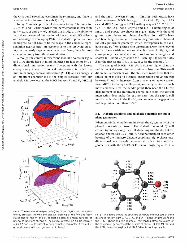
In Fig. 7, we also provide plots similar to Fig. 6 but now forU1, U3, V1, and V2. This provides another view of the intersectionat r ¼ 2.232 A and f ¼ 0�, labeled CI2 in Fig. 2. The ability toreproduce the conical intersection with our diabatic PES reectsone advantage of developing PESs in a diabatic representation –
namely we do not have to t the cusps in the adiabatic repre-sentation near conical intersections or to line up avoid cross-ings in the nearly degenerate adiabatic surfaces; these featuresemerge naturally from the diagonalization.
Although the conical intersections look like points in Fig. 6and 7, we should keep in mind that these are just points on 31-dimensional intersection seams. The point with the lowestenergy along a seam of conical intersections is called theminimum energy conical intersection (MECI), and its energy isan important characteristic of the coupled surfaces. With ouranalytic PESs, we located the MECI between V2 and V3 (MECI1)
Fig. 7 Three-dimensional plots of (a) the U1 and U3 diabatic potential-energy surfaces showing the diabatic crossing of the 1pp and 1ps*
states and (b) the V1 and V2 adiabatic potential-energy surfaces ofphenol as functions of r and f. The conical intersection (CI2) is seen at r¼ 2.23 A and f ¼ 0� with all other geometric parameters fixed at theground state equilibrium geometry of phenol.
and the MECI between V1 and V2 (MECI2). Both MECIs haveplanar structures. MECI1 has rOH ¼ 1.273 A with V2 ¼ V3 ¼ 5.35eV and MECI2 has rOH ¼ 1.971 A with V1 ¼ V2 ¼ 4.17 eV. The C–C, C–O, and O–H bond lengths and C–O–H bond angles ofMECI1 and MECI2 are shown in Fig. 8, along with those ofground state phenol and phenoxyl radical. Both MECIs haveC–C bond lengths similar to those in the ground-state phenoxylradical equilibrium geometry, which corresponds to the dia-batic state U3 (
1ps*); these ring distortions lower the energy ofthe 1ps* state with respect to what is shown in Fig. 2, andconsequently the conical intersections have lower energies andshorter O–H bond lengths than the CIs in Fig. 2 (1.273 vs. 1.316A for the rst CI and 1.971 vs. 2.231 A for the second CI).
The energy of MECI1, 5.35 eV, is 0.21 eV higher than thesaddle point discussed in the previous subsection. This smalldifference is consistent with the statement made there that thesaddle point is close to a conical intersection and yet the gapbetween V2 and V3 increases from 0 to 0.81 eV as one movesfrom MECI1 to the V2 saddle point, so the dynamics is muchmore adiabatic near the saddle point than near the CI. Thedisplacement of the minimum energy path from the conicalintersection does make the gap nonzero, but the gap is stillmuch smaller than in the H + H2 reaction where the gap at thesaddle point is more than 6 eV.122
3.4. Diabatic couplings and adiabatic potentials for out-of-plane geometries
When out-of-plane modes are involved, the Cs symmetry of thephenol molecule is broken. The diabatic potential U3 stillcrosses U2 and U1 along the O–H stretching coordinate, but theadiabatic potentials V1, V2, and V3 need not intersect each otherbecause of the non-zero diabatic couplings. Fig. 9 shows one-dimensional cuts through the potential surfaces for nonplanargeometries with the C2–C1–O–H torsion angle equal to f ¼
Fig. 8 The figure shows the structure of MECI1 and four sets of bonddistances for key eight C–C, C–O, and O–H bond lengths (in A) andthe C–O–H bond angle (in degrees). From top to bottom are values forthe equilibrium geometry of the S0 state of phenol, MECI1, MECI2, andthe ~X 2B1 state phenoxyl radical. “N.A.” denotes not applicable.
145�. The phenoxyl ring is xed at the ground state equilibriumgeometry of phenol with qCOH ¼ 107� and 130� in Fig. 9a and b;the phenoxyl ring is xed at the transition state geometry of theS1 excited state with qCOH ¼ 112� in Fig. 9c; and the phenoxylring is xed at the ground-state equilibrium geometry of phe-noxyl radical with qCOH ¼ 115� in Fig. 9d. In all cases, theadiabatic potential curves show avoided intersections along theO–H stretching coordinate, as expected.
Near conical intersections, diabatic potential energy curvesmay cross along the C2–C1–O–H torsion coordinate. But adia-batic potential energy curves avoid crossing since the nonzerodiabatic couplings li the degeneracy of diabatic states. This isshown clearly in Fig. 10. In Fig. 10a, for rOH ¼ 1.29 A with allother geometric parameters except f xed at the ground equi-librium geometry of phenol, the diabatic potential U3 crosses U2
at f ¼ 25�, but the adiabatic potential curves V2 and V3 avoidcrossing. In Fig. 10b, for rOH ¼ 2.10 A, the diabatic potential U3
crosses U1 at f¼ 24�, but again the adiabatic potential curves V1and V2 avoid crossing.
So far we have shown cuts through the APRP PESs for a xedgeometry of the phenoxyl moiety of phenol. The good perfor-mance of our APRP PES for those geometries is expected sincewe used general functional forms to t the dependence of MC-QDPT diabatic potentials and couplings on the primary andsecondary coordinates. Next we examine the PESs for somenonplanar geometries with distorted phenoxyl groups. In thelanguage of the APRP, we are looking here at how the PESs andcouplings vary for geometries with distortions in tertiary
Fig. 9 Diabatic potentials (U1, U2, and U3) and adiabatic potentials (V1, V2,geometric parameters fixed at the ground state equilibrium geometry ofground state equilibriumgeometry of phenol, (c) all other geometric para(d) qCOH ¼ 115� and all other geometric parameters fixed at the ground
4674 | Chem. Sci., 2014, 5, 4661–4680
coordinates. In particular, we examine the dependence on then16a (an out-of-plane ring puckering/twisting vibration of a0 0
symmetry) and n16b modes that have been singled out forattention in experimental studies.46,51 (We use Wilson's labelingscheme123 for the phenol and phenoxyl vibrational modes.)
The diabatic potentials and relevant diabatic couplingsalong Cartesian normal-mode displacements of the n16a andn16b modes were calculated with our APRP PESs and comparedwith MC-QDPT results at the two conical intersections inFig. 11 and 12. The normalized Cartesian normal-modedisplacements of n16a and n16b modes calculated by the M06-Lfunctional124 with the aug-cc-pVTZ basis set were used in orderto be consistent with previous MC-QDPT calculations.33 TheAPRP diabatic potentials and couplings agree qualitativelywith the MC-QDPT results. The diabatic coupling U23
increases linearly along the Cartesian normal-modedisplacements of both n16a and n16b modes at CI1. At CI2, thediabatic coupling U13 also increases linearly along the Carte-sian normal-mode displacement of the n16a mode. However, itremains very small along the Cartesian normal-modedisplacement of the n16b mode. These calculations of thediabatic couplings for out-of-plane distortion of the ring inphenol can be used in the future for full-dimensional studiesof the effects of vibrational mode coupling on the dynamics ofphotodissociation of phenol. However, we can also gaininsight into the photodissociation dynamics by studying thecouplings even without carrying out full dynamics studies,and we consider that next.
and V3) versus rOH with C2–C1–O–H torsion fCCOH¼ 145�, (a) all otherphenol, (b) qCOH ¼ 130� and all other geometric parameters fixed at themeters fixed at the excited state (S1) transition state geometry of phenol,state equilibrium geometry of phenoxyl radical.
Fig. 10 Diabatic potentials (U1, U2, andU3) and adiabatic potentials (V1,V2, and V3) versusC2–C1–O–H torsion fCCOH (a) with rOH¼ 1.29 A andall other geometric parameters fixed at the ground state equilibriumgeometry of phenol, (b) with rOH ¼ 2.10 A and all other geometricparameters fixed at the ground state equilibrium geometry of phenol.
Fig. 11 The atomic displacements of vibrational mode n16a (a), andcalculated and APRP diabatic potentials and the most relevant diabaticcouplings at conical intersections of the 1pp* and 1ps* states (b) andthe 1pp and 1ps* states (c) along scaled Cartesian normal-modedisplacements.
Edge Article Chemical Science
Publ
ishe
d on
06
Aug
ust 2
014.
Dow
nloa
ded
by U
nive
rsity
of
Min
neso
ta -
Tw
in C
ities
on
07/1
2/20
14 1
7:50
:28.
View Article Online
First we recall the Ehrenfest effective PES, which we will call�V , for multi-electronic-state molecular dynamics is a weightedaverage over the adiabatic PESs, Vj, where the weights are thediagonal elements, rjj, of the electronic density matrix.34,125–128
Then we consider a photoexcited system with r22 [ r11 and r22
[ r33 approaching CI1. If the system is not adiabatic, we expectto see r33 increase, and that puts a higher weight on V3 andraises �V , which makes it less likely that the system dissociates.Now let the system undergo a vibration in an out-of-plane modewhile it approaches CI1; this has two consequences: (1) thevibration causes U2 and V2 to go up, which raises �V , decreasingthe probability of dissociation; and (2) the vibration causes |U23|to go up, which makes the system more adiabatic, which keepsr33 low, which tends to keep �V low, which increases the prob-ability of dissociation. For some modes, call them “inactive”modes, effect (1) may dominate. For other modes, call them“active” modes, effect (2) may dominate. We conclude thatreaction will preferentially occur through those molecules thathappen to have active modes excited as they get to CI1.
When one experimentally observes the products (as Ashfoldand coworkers46,51 do), one will then see an excess of moleculeswith active modes excited since those are the ones that prefer-entially reacted. Under the conditions of the experiments, mostof the vibrational modes are initially in their ground vibrational
state. Let qm be an out-of-plane vibrational mode, and let Zm bethe zero point energy in that mode. Near a planar geometry,
U2 ¼ U2ðq ¼ 0Þ þ 1
2kmqm
2; (22)
and
U23 ¼ Cmqm, (23)
where km is a force constant, and Cm depends on the t to thediabatic couplings. (Both km and Cm depend on geometry in theAPRP.) Let Dm¼ |Cm|, and let Qm be the harmonic turning pointof qm:
Fig. 12 The atomic displacements of vibrational mode n16b (a), andcalculated and APRP diabatic potentials and the most relevant diabaticcouplings at conical intersections of the 1pp* and 1ps* states (b) andthe 1pp and 1ps* states (c) along scaled Cartesian normal-modedisplacements.
This is the simplest unitless quantity that goes up when |U23|goes up and is larger when the rise in U2 is smaller.
We calculated X(Qm) for all out-of-plane modes at a planargeometry of the S1 state of phenol that has the same OHdistance as the transition state but the rest of the coordinatesare the same as in the equilibrium geometry of the S1 state. Wefound that X(Qm) is 0.12 for mode n16a (103 cm�1), 0.064 formode 11 (197 cm�1), and 0.050 for mode 10a (389 cm�1), but itranges between 0.013 and 2 � 10�4 for the other seven out-of-plane modes of phenol (with frequencies in the range 92–865cm�1). This provides a simple explanation for why n16a mode isthe most prominent excited mode observed46,51 in the productsof the photodissociation reaction; and we note that mode 10a is
4676 | Chem. Sci., 2014, 5, 4661–4680
also observed51 to be excited in the products. We note thatvibrational modes can also be excited during the energy releasephase as the system progresses from the region of the saddlepoint and CI1 down to products, but the analysis just given isconsistent with the interpretation51 of at least some of theobserved vibrational mode selectivity as arising from the abilityof various vibrational modes to promote state coupling.Unfortunately this is called promotion of “nonadiabatic tran-sitions” in ref. 51, but actually—as the above discussion shouldmake clear—the relevant consideration is promotion of diabaticcoupling, which leads to adiabatic passage, not nonadiabatictransitions.
3.5. Nonplanar conical intersections
The conical intersections occur in a (3N � 8)-dimensionalmanifold, where N is the number of atoms. Thus, in phenolmolecule, the conical intersection should have a dimension of31. Both U13 and U23 vanish for planar geometries, which forma 23-dimensional manifold, because 2N � 3 ¼ 23. With thefurther constraint of U2 ¼ U3 or U1 ¼ U3, the
1pp*/1ps* and1pp/1ps* conical intersections occur in a 22-dimensionalmanifold in planar geometry. This is a relatively low-dimen-sional subset of the full 31-dimensional seam, and thereforemost of the conical intersection seam has nonplanargeometry.
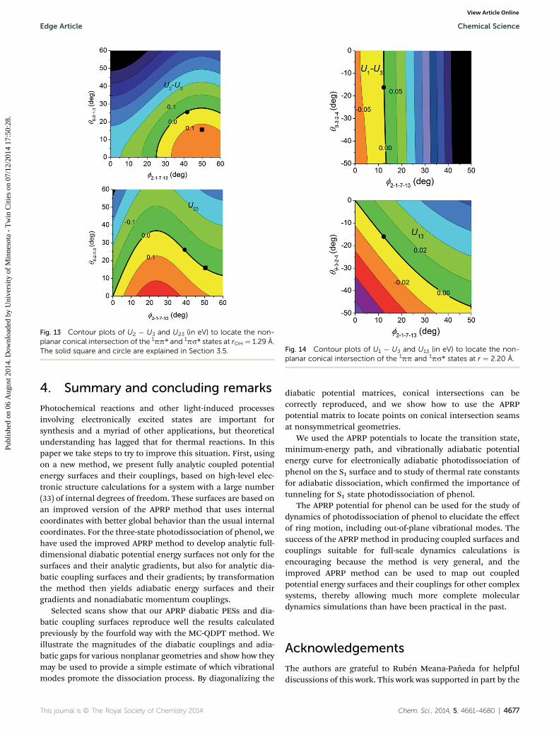
Locating conical intersections that are not determined bysymmetry can be carried out by special algorithms in theadiabatic representation.129,130 However, with the analyticdiabatic PES matrices of phenol on hand, we can locate suchconical intersections more easily.131,132 Contour plots of U2 �U3 and U23 with respect to the C2–C1–O–H torsion angle f andone of the H out-of-plane bend angles, in particular q8�2�1�3,which denotes the deviation of atom 8 from the 2�1�3 plane,are shown in Fig. 13 at r ¼ 1.29 A. At the planar geometries,both f and q8�2�1�3 are zero, and adiabatic state V3 is 0.21 eVhigher in energy than adiabatic state V2. The seam with U22 ¼U33 ¼ 0 and the seam with U23 ¼ 0 cross at f ¼ 40.1� andq8�2�1�3 ¼ 25.0�. If these two diabatic states formed a closedspace, that point (solid circle in Fig. 13) will be a nonplanarconical intersection of V2 and V3, but due to the perturbationby diabatic state U1, the location of the true conical inter-section is displaced from this point. Nevertheless this is agood starting point for a search, and by making a contourplot of V2 � V3 in this vicinity (which is inexpensive becausewe have an analytic representation), we nd that V2 ¼ V3 ¼5.93 eV at f ¼ 49.3� and q8�2�1�3 ¼ 15.8� (solid square inFig. 13).
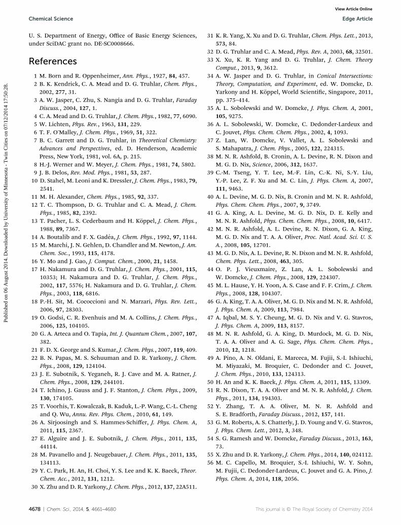
In Fig. 14, we present the contour plots of U1 � U3 and U13
with respect to the C2–C1–O–H torsion angle f and one of the Hout-of-plane bend angles q9�3�2�4 at r ¼ 2.20 A. The seam withU1 � U3 ¼ 0 eV and the seam with U13 ¼ 0 eV cross at f2�1�7�13
¼ 12.4� and q9�3�2�4 ¼ �16.2� which is also a nonplanarconical intersection with V1 ¼ V2 ¼ 4.54 eV as a result of thesmallness of the perturbation by diabatic state U2 at thisgeometry.
Fig. 13 Contour plots of U2 � U3 and U23 (in eV) to locate the non-planar conical intersection of the 1pp* and 1ps* states at rOH ¼ 1.29 A.The solid square and circle are explained in Section 3.5. Fig. 14 Contour plots of U1 � U3 and U13 (in eV) to locate the non-
planar conical intersection of the 1pp and 1ps* states at r ¼ 2.20 A.
Edge Article Chemical Science
Publ
ishe
d on
06
Aug
ust 2
014.
Dow
nloa
ded
by U
nive
rsity
of
Min
neso
ta -
Tw
in C
ities
on
07/1
2/20
14 1
7:50
:28.
View Article Online
4. Summary and concluding remarks
Photochemical reactions and other light-induced processesinvolving electronically excited states are important forsynthesis and a myriad of other applications, but theoreticalunderstanding has lagged that for thermal reactions. In thispaper we take steps to try to improve this situation. First, usingon a new method, we present fully analytic coupled potentialenergy surfaces and their couplings, based on high-level elec-tronic structure calculations for a system with a large number(33) of internal degrees of freedom. These surfaces are based onan improved version of the APRP method that uses internalcoordinates with better global behavior than the usual internalcoordinates. For the three-state photodissociation of phenol, wehave used the improved APRP method to develop analytic full-dimensional diabatic potential energy surfaces not only for thesurfaces and their analytic gradients, but also for analytic dia-batic coupling surfaces and their gradients; by transformationthe method then yields adiabatic energy surfaces and theirgradients and nonadiabatic momentum couplings.
Selected scans show that our APRP diabatic PESs and dia-batic coupling surfaces reproduce well the results calculatedpreviously by the fourfold way with the MC-QDPT method. Weillustrate the magnitudes of the diabatic couplings and adia-batic gaps for various nonplanar geometries and show how theymay be used to provide a simple estimate of which vibrationalmodes promote the dissociation process. By diagonalizing the
diabatic potential matrices, conical intersections can becorrectly reproduced, and we show how to use the APRPpotential matrix to locate points on conical intersection seamsat nonsymmetrical geometries.
We used the APRP potentials to locate the transition state,minimum-energy path, and vibrationally adiabatic potentialenergy curve for electronically adiabatic photodissociation ofphenol on the S1 surface and to study of thermal rate constantsfor adiabatic dissociation, which conrmed the importance oftunneling for S1 state photodissociation of phenol.
The APRP potential for phenol can be used for the study ofdynamics of photodissociation of phenol to elucidate the effectof ring motion, including out-of-plane vibrational modes. Thesuccess of the APRP method in producing coupled surfaces andcouplings suitable for full-scale dynamics calculations isencouraging because the method is very general, and theimproved APRP method can be used to map out coupledpotential energy surfaces and their couplings for other complexsystems, thereby allowing much more complete moleculardynamics simulations than have been practical in the past.
Acknowledgements
The authors are grateful to Ruben Meana-Paneda for helpfuldiscussions of this work. This work was supported in part by the
U. S. Department of Energy, Office of Basic Energy Sciences,under SciDAC grant no. DE-SC0008666.
References
1 M. Born and R. Oppenheimer, Ann. Phys., 1927, 84, 457.2 B. K. Kendrick, C. A. Mead and D. G. Truhlar, Chem. Phys.,2002, 277, 31.
3 A. W. Jasper, C. Zhu, S. Nangia and D. G. Truhlar, FaradayDiscuss., 2004, 127, 1.
4 C. A. Mead and D. G. Truhlar, J. Chem. Phys., 1982, 77, 6090.5 W. Lichten, Phys. Rev., 1963, 131, 229.6 T. F. O'Malley, J. Chem. Phys., 1969, 51, 322.7 B. C. Garrett and D. G. Truhlar, in Theoretical Chemistry:Advances and Perspectives, ed. D. Henderson, AcademicPress, New York, 1981, vol. 6A, p. 215.
8 H.-J. Werner and W. Meyer, J. Chem. Phys., 1981, 74, 5802.9 J. B. Delos, Rev. Mod. Phys., 1981, 53, 287.10 D. Stahel, M. Leoni and K. Dressler, J. Chem. Phys., 1983, 79,
2541.11 M. H. Alexander, Chem. Phys., 1985, 92, 337.12 T. C. Thompson, D. G. Truhlar and C. A. Mead, J. Chem.
Phys., 1985, 82, 2392.13 T. Pacher, L. S. Cederbaum and H. Koppel, J. Chem. Phys.,
1988, 89, 7367.14 A. Boutalib and F. X. Gadea, J. Chem. Phys., 1992, 97, 1144.15 M. Marchi, J. N. Gehlen, D. Chandler and M. Newton, J. Am.
Chem. Soc., 1993, 115, 4178.16 Y. Mo and J. Gao, J. Comput. Chem., 2000, 21, 1458.17 H. Nakamura and D. G. Truhlar, J. Chem. Phys., 2001, 115,
10353; H. Nakamura and D. G. Truhlar, J. Chem. Phys.,2002, 117, 5576; H. Nakamura and D. G. Truhlar, J. Chem.Phys., 2003, 118, 6816.
18 P.-H. Sit, M. Cococcioni and N. Marzari, Phys. Rev. Lett.,2006, 97, 28303.
19 O. Godsi, C. R. Evenhuis and M. A. Collins, J. Chem. Phys.,2006, 125, 104105.
20 G. A. Arteca and O. Tapia, Int. J. Quantum Chem., 2007, 107,382.
21 F. D. X. George and S. Kumar, J. Chem. Phys., 2007, 119, 409.22 B. N. Papas, M. S. Schuuman and D. R. Yarkony, J. Chem.
Phys., 2008, 129, 124104.23 J. E. Subotnik, S. Yeganeh, R. J. Cave and M. A. Ratner, J.
Chem. Phys., 2008, 129, 244101.24 T. Ichino, J. Gauss and J. F. Stanton, J. Chem. Phys., 2009,
130, 174105.25 T. Voorhis, T. Kowalczak, B. Kaduk, L.-P. Wang, C.-L. Cheng
and Q. Wu, Annu. Rev. Phys. Chem., 2010, 61, 149.26 A. Sirjoosingh and S. Hammes-Schiffer, J. Phys. Chem. A,
2011, 115, 2367.27 E. Alguire and J. E. Subotnik, J. Chem. Phys., 2011, 135,
44114.28 M. Pavanello and J. Neugebauer, J. Chem. Phys., 2011, 135,
134113.29 Y. C. Park, H. An, H. Choi, Y. S. Lee and K. K. Baeck, Theor.
Chem. Acc., 2012, 131, 1212.30 X. Zhu and D. R. Yarkony, J. Chem. Phys., 2012, 137, 22A511.
4678 | Chem. Sci., 2014, 5, 4661–4680
31 K. R. Yang, X. Xu and D. G. Truhlar, Chem. Phys. Lett., 2013,573, 84.
32 D. G. Truhlar and C. A. Mead, Phys. Rev. A, 2003, 68, 32501.33 X. Xu, K. R. Yang and D. G. Truhlar, J. Chem. Theory
Comput., 2013, 9, 3612.34 A. W. Jasper and D. G. Truhlar, in Conical Intersections:
Theory, Computation, and Experiment, ed. W. Domcke, D.Yarkony and H. Koppel, World Scientic, Singapore, 2011,pp. 375–414.
35 A. L. Sobolewski and W. Domcke, J. Phys. Chem. A, 2001,105, 9275.
36 A. L. Sobolewski, W. Domcke, C. Dedonder-Lardeux andC. Jouvet, Phys. Chem. Chem. Phys., 2002, 4, 1093.
37 Z. Lan, W. Domcke, V. Vallet, A. L. Sobolewski andS. Mahapatra, J. Chem. Phys., 2005, 122, 224315.
38 M. N. R. Ashfold, B. Cronin, A. L. Devine, R. N. Dixon andM. G. D. Nix, Science, 2006, 312, 1637.
39 C.-M. Tseng, Y. T. Lee, M.-F. Lin, C.-K. Ni, S.-Y. Liu,Y.-P. Lee, Z. F. Xu and M. C. Lin, J. Phys. Chem. A, 2007,111, 9463.
40 A. L. Devine, M. G. D. Nix, B. Cronin and M. N. R. Ashfold,Phys. Chem. Chem. Phys., 2007, 9, 3749.
41 G. A. King, A. L. Devine, M. G. D. Nix, D. E. Kelly andM. N. R. Ashfold, Phys. Chem. Chem. Phys., 2008, 10, 6417.
42 M. N. R. Ashfold, A. L. Devine, R. N. Dixon, G. A. King,M. G. D. Nix and T. A. A. Oliver, Proc. Natl. Acad. Sci. U. S.A., 2008, 105, 12701.
43 M. G. D. Nix, A. L. Devine, R. N. Dixon and M. N. R. Ashfold,Chem. Phys. Lett., 2008, 463, 305.
44 O. P. J. Vieuxmaire, Z. Lan, A. L. Sobolewski andW. Domcke, J. Chem. Phys., 2008, 129, 224307.
45 M. L. Hause, Y. H. Yoon, A. S. Case and F. F. Crim, J. Chem.Phys., 2008, 128, 104307.
46 G. A. King, T. A. A. Oliver, M. G. D. Nix andM. N. R. Ashfold,J. Phys. Chem. A, 2009, 113, 7984.
47 A. Iqbal, M. S. Y. Cheung, M. G. D. Nix and V. G. Stavros,J. Phys. Chem. A, 2009, 113, 8157.
48 M. N. R. Ashfold, G. A. King, D. Murdock, M. G. D. Nix,T. A. A. Oliver and A. G. Sage, Phys. Chem. Chem. Phys.,2010, 12, 1218.
49 A. Pino, A. N. Oldani, E. Marceca, M. Fujii, S.-I. Ishiuchi,M. Miyazaki, M. Broquier, C. Dedonder and C. Jouvet,J. Chem. Phys., 2010, 133, 124313.
50 H. An and K. K. Baeck, J. Phys. Chem. A, 2011, 115, 13309.51 R. N. Dixon, T. A. A. Oliver and M. N. R. Ashfold, J. Chem.
Phys., 2011, 134, 194303.52 Y. Zhang, T. A. A. Oliver, M. N. R. Ashfold and
S. E. Bradforth, Faraday Discuss., 2012, 157, 141.53 G. M. Roberts, A. S. Chatterly, J. D. Young and V. G. Stavros,
J. Phys. Chem. Lett., 2012, 3, 348.54 S. G. Ramesh and W. Domcke, Faraday Discuss., 2013, 163,
73.55 X. Zhu and D. R. Yarkony, J. Chem. Phys., 2014, 140, 024112.56 M. C. Capello, M. Broquier, S.-I. Ishiuchi, W. Y. Sohn,
M. Fujii, C. Dedonder-Lardeux, C. Jouvet and G. A. Pino, J.Phys. Chem. A, 2014, 118, 2056.
57 T. N. V. Karsili, A. M. Wenge, B. Marchetti andM. N. R. Ashfold, Phys. Chem. Chem. Phys., 2014, 16, 588.
58 B. J. Braams and J. M. Bowman, Int. Rev. Phys. Chem., 2009,28, 577.
59 J. M. Bowman, B. J. Braams, S. Carter, C. Chen, G. Czako,B. Fu, X. Huang, E. Kamarchik, A. R. Sharma,B. C. Shepler, Y. Wang and Z. Xie, J. Phys. Chem. Lett.,2010, 1, 1866.
60 Y. Paukku, K. R. Yang, Z. Varga and D. G. Truhlar, J. Chem.Phys., 2013, 139, 044309.
61 R. Dawes, D. L. Thompson, Y. Guo, A. F. Wagner andM. Minkoff, J. Chem. Phys., 2007, 126, 184108.
62 Y. Guo, I. Tokmakov, D. L. Thompson, A. F. Wagner andM. Minkoff, J. Chem. Phys., 2007, 127, 214106.
63 J. D. Bender, S. Doraiswamy, D. G. Truhlar and G. Candler,J. Chem. Phys., 2014, 140, 054302.
64 K. R. Yang, X. Xu and D. G. Truhlar, J. Chem. TheoryComput., 2014, 10, 924.
65 B. Wang, K. R. Yang, X. Xu, M. Isegawa, H. R. Leverentz andD. G. Truhlar, Acc. Chem. Res., DOI: 10.1021/ar500068a,online as Article ASAP.
66 S. Dasgupta and W. A. Goddard III, J. Chem. Phys., 1989, 90,7207.
67 V. Barone, I. Cacelli, N. De Mitri, D. Licari, S. Monti andG. Prampolini, Phys. Chem. Chem. Phys., 2013, 15, 3736.
68 H. Nakano, J. Chem. Phys., 1993, 99, 7983; H. Nakano, Chem.Phys. Lett., 1993, 207, 372.
69 E. Papajak and D. G. Truhlar, J. Chem. Theory Comput.,2011, 7, 10.
70 P. Siegbahn, A. Heiberg, B. O. Roos and B. A. Levy, Phys.Scr., 1980, 21, 323; B. O. Roos, P. R. Taylor andP. E. M. Siegbahn, Chem. Phys., 1980, 48, 157;K. Ruedenberg, M. W. Schmidt, G. M. Gilbert andS. T. Elbert, Chem. Phys., 1982, 71, 41.
71 T. H. Dunning, Jr, J. Chem. Phys., 1989, 90, 1007;R. A. Kendall and T. H. Dunning, Jr, J. Chem. Phys., 1992,96, 6796.
72 Y. P. Varshni, Rev. Mod. Phys., 1957, 29, 664, erratum: 1959,31, 839.
73 P. M. Morse, Phys. Rev., 1929, 34, 1957.74 Y. Zhao and D. G. Truhlar, Theor. Chem. Acc., 2008, 120, 215.75 M. E. Casida, C. Jamorski, K. C. Casida and D. R. Salahub,
J. Chem. Phys., 1998, 108, 4439.76 R. E. Stratmann, G. E. Scuseria and M. J. Frisch, J. Chem.
Phys., 1998, 109, 8218.77 G. Simons, R. G. Parr and J. M. Finlan, J. Chem. Phys., 1973,
84, 891.78 S. Gupta, K. Dharamvir and V. K. Jindal, Int. J. Mod. Phys. B,
2004, 18, 1021.79 G. Pongor, G. Fogarasi, J. E. Boggs and P. Pulay, J. Mol.
Spectrosc., 1985, 114, 445.80 See ESI† at [URL will be inserted by RSC] for additional
details of the tting of the potential energy surfaces andthe full set of nal parameters.
81 R. J. Duchovic, Y. L. Volobuev, G. C. Lynch, T. C. Allison,J. C. Corchado, D. G. Truhlar, A. F. Wagner and
B. C. Garrett, Comput. Phys. Commun., 2002, 144, 169–187,erratum: 2004, 156, 319–322.
82 See http://comp.chem.umn.edu/potlib/for the latest versionof POTLIB that includes the phenol potential energy surfacematrix presented in this paper.
83 H. Nakamura, J. D. Xidos, A. C. Chamberlin, C. P. Kelly,R. Valero, K. R. Yang, J. D. Thompson, J. Li,G. D. Hawkins, T. Zhu, B. J. Lynch, Y. Volobuev,D. Rinaldi, D. A. Liotard, C. J. Cramer and D. G. Truhlar,HONDOPLUS-v5.2, University of Minnesota, Minneapolis,MN, 2013.
84 M. J. Frisch, G. W. Trucks, H. B. Schlegel, G. E. Scuseria,M. A. Robb, J. R. Cheeseman, G. Scalmani, V. Barone,B. Mennucci, G. A. Petersson, H. Nakatsuji, M. Caricato,X. Li, H. P. Hratchian, A. F. Izmaylov, J. Bloino, G. Zheng,J. L. Sonnenberg, M. Hada, M. Ehara, K. Toyota,R. Fukuda, J. Hasegawa, M. Ishida, T. Nakajima,Y. Honda, O. Kitao, H. Nakai, T. Vreven,J. A. Montgomery, Jr J. E. Peralta, F. Ogliaro, M. Bearpark,J. J. Heyd, E. Brothers, K. N. Kudin, V. N. Staroverov,R. Kobayashi, J. Normand, K. Raghavachari, A. Rendell,J. C. Burant, S. S. Iyengar, J. Tomasi, M. Cossi, N. Rega,J. M. Millam, M. Klene, J. E. Knox, J. B. Cross, V. Bakken,C. Adamo, J. Jaramillo, R. Gomperts, R. E. Stratmann,O. Yazyev, A. J. Austin, R. Cammi, C. Pomelli,J. W. Ochterski, R. L. Martin, K. Morokuma,V. G. Zakrzewski, G. A. Voth, P. Salvador,J. J. Dannenberg, S. Dapprich, A. D. Daniels, O. Farkas,J. B. Foresman, J. V. Ortiz, J. Cioslowski and D. J. Fox,Gaussian 09, Revision D.01, Gaussian, Inc., WallingfordCT, 2009.
85 J. Zheng, S. Zhang, B. J. Lynch, J. C. Corchado, Y.-Y. Chuang,P. L. Fast, W.-P. Hu, Y.-P. Liu, G. C. Lynch, K. A. Nguyen,C. F. Jackels, A. Fernandez Ramos, B. A. Ellingson,V. S. Melissas, J. Villa, I. Rossi, E. L. Coitino, J. Pu,T. V. Albu, R. Steckler, B. C. Garrett, A. D. Isaacson andD. G. Truhlar, POLYRATE–version 2010, University ofMinnesota, Minneapolis, 2010.
86 J. Zheng, Z. H. Li, A. W. Jasper, D. A. Bonhommeau,R. Valero, R. Meana-Paneda and D. G. Truhlar, ANT–version 2014, University of Minnesota, Minneapolis, MN,2014, http://comp.chem.umn.edu/ant, accessed May 262014.
87 N. W. Larsen, J. Mol. Struct., 1979, 51, 175.88 G. Portalone, G. Schultz, A. Domenicano and I. Hargittai,
Chem. Phys. Lett., 1992, 197, 482.89 D. Spangenberg, P. Imhof and K. Kleinermanns, Phys.
Chem. Chem. Phys., 2003, 5, 2505.90 C.-W. Cheng, Y.-P. Lee and H. A. Witek, J. Phys. Chem. A,
2008, 112, 2648.91 F. van Bolhuis and C. T. Kiers, Acta Crystallogr., Sect. B:
Struct. Crystallogr. Cryst. Chem., 1978, 34, 1015.92 G. Keresztury, F. Billes, M. Kubinyi and T. Sundius, J. Phys.
Chem. A, 1998, 102, 1371.93 J. Spanget-Larsen, M. Gil, A. Gorski, D. M. Blake, J. Waluk
and J. G. Radziszewski, J. Am. Chem. Soc., 2003, 123, 11253.
94 I. M. Alecu, J. Zheng, Y. Zhao and D. G. Truhlar, J. Chem.Theory Comput., 2010, 6, 2872.
95 R. C. Fuh, Oregon Medical Laser Center, Portland, OR,1995, http://omlc.ogi.edu/spectra/PhotochemCAD/html/072.html, accessed May 17 2014.
96 R. F. Gunion, M. K. Gilles, M. L. Polak andW. C. Lineberger,Int. J. Mass Spectrom. Ion Processes, 1992, 117, 602.
97 J. G. Radziszewski, M. Gil, A. Gorski, J. Spanger-Larsen,J. Waluk and B. J. Mroz, J. Chem. Phys., 2001, 115, 9733.
98 Y.-R. Luo, Handbook of Bond Dissociation Energies in OrganicCompounds, University of Science and Technology of China,Hefei, 2006, p. 182.
99 H. D. Bist, J. C. D. Brand and D. R. Williams, J. Mol.Spectrosc., 1966, 21, 76; H. D. Bist, J. C. D. Brand andD. R. Williams, J. Mol. Spectrosc., 1967, 24, 402; H. D. Bist,J. C. D. Brand and D. R. Williams, J. Mol. Spectrosc., 1967,24, 413.
100 O. Tishchenko, D. G. Truhlar, A. Ceulemans andM. T. Nguyen, J. Am. Chem. Soc., 2008, 130, 7000.
101 D. G. Truhlar and A. Kuppermann, J. Am. Chem. Soc., 1971,93, 1840.
102 A. D. Isaacson and D. G. Truhlar, J. Chem. Phys., 1981, 75,4090.
103 M. Page and J. W. McIver, Jr, J. Chem. Phys., 1988, 88, 922.104 J. O. Hirschfelder and E. Wigner, J. Chem. Phys., 1939, 7,
616.105 M. A. Eliason and J. O. Hirschfelder, J. Chem. Phys., 1959,
30, 1426.106 R. A. Marcus, J. Chem. Phys., 1967, 46, 959.107 R. T. Skodje, D. G. Truhlar and B. C. Garrett, J. Chem. Phys.,
1982, 77, 5955.108 Y.-P. Liu, G. C. Lynch, T. N. Truong, D.-h. Lu, D. G. Truhlar
and B. C. Garrett, J. Am. Chem. Soc., 1993, 115, 2408.109 D. C. Chateld, R. S. Friedman, D. G. Truhlar, B. C. Garrett
and D. W. Schwenke, J. Am. Chem. Soc., 1991, 113, 486.110 A. Tachibana and K. Fukui, Theor. Chem. Acta, 1979, 51,
189.111 G. C. Hancock, P. Rejto, R. Steckler, F. B. Brown,
D. W. Schwenke and D. G. Truhlar, J. Chem. Phys., 1986,85, 4997.
4680 | Chem. Sci., 2014, 5, 4661–4680
112 D. G. Truhlar, A. D. Isaacson, R. T. Skodje and B. C. Garrett,J. Phys. Chem., 1982, 86, 2252.
113 D. G. Truhlar, A. D. Isaacson and B. C. Garrett, in The Theoryof Chemical Reaction Dynamics, ed. M. Baer, CRC Press, BocaRaton FL, 1985, vol. 4, pp. 65–137.
114 A. Fernandez-Ramos, B. A. Ellingson, B. C. Garrett andD. G. Truhlar, Rev. Comput. Chem., 2007, 23, 125.
115 B. C. Garrett, D. G. Truhlar, A. F. Wagner andT. H. Dunning, Jr, J. Chem. Phys., 1983, 78, 4400.
116 A. Fernandez-Ramos and D. G. Truhlar, J. Chem. Phys.,2001, 114, 1491.
117 Y.-P. Liu, D.-h. Lu, A. Gonzalez-Lafont, D. G. Truhlar andB. C. Garrett, J. Am. Chem. Soc., 1993, 115, 7806.
118 B. C. Garrett and D. G. Truhlar, J. Chem. Phys., 1983, 79,4931.
119 R. Meana-Paneda, D. G. Truhlar and A. Fernandez-Ramos,J. Chem. Theory Comput., 2010, 6, 6.
120 J. G. Lauderdale and D. G. Truhlar, Surf. Sci., 1985, 164, 558.121 S. E. Wonchoba, W.-P. Hu and D. G. Truhlar, in Theoretical
and Computational Approaches to Interface Phenomena, ed.H. L. Sellers and J. T. Golab, Plenum, New York, 1994, p. 7.
122 A. J. C. Varandas, F. B. Brown, C. A. Mead, D. G. Truhlar andN. C. Blais, J. Chem. Phys., 1987, 86, 6258.
123 E. B. Wilson, Phys. Rev., 1934, 45, 706.124 Y. Zhao and D. G. Truhlar, J. Chem. Phys., 2006, 125, 194101.125 H.-D. Meyer andW. H.Miller, J. Chem. Phys., 1979, 70, 1334.126 A. D. Micha, J. Chem. Phys., 1983, 78, 7138.127 M. Amarouche, F. X. Gadea and J. Durup, Chem. Phys.,
1989, 130, 145.128 M. D. Hack and D. G. Truhlar, J. Chem. Phys., 2001, 114,
9305.129 M. J. Bearpark, M. A. Robb and H. B. Schlegel, Chem. Phys.
Lett., 1994, 223, 269.130 M. Dallos, H. Lischka, R. Shepard, D. R. Yarkony and
P. G. Szalay, J. Chem. Phys., 2004, 120, 7330.131 S. Nangia and D. G. Truhlar, J. Chem. Phys., 2006, 124,
124309.132 Z. H. Li, R. Valero and D. G. Truhlar, Theor. Chem. Acc.,